Underfloor Air Distribution (UFAD) Design Guide - CTGN · This publication was prepared under...
255
Underfloor Air Distribution (UFAD) Design Guide
Transcript of Underfloor Air Distribution (UFAD) Design Guide - CTGN · This publication was prepared under...

Underfloor Air Distribution (UFAD)Design Guide

This publication was prepared under ASHRAE Research Project RP-1064 in cooperation with TC 5.3, Room Air Distribution.
ABOUT THE AUTHOR
Fred S. Bauman, P.E., is a research specialist with the Center forthe Built Environment (CBE) at the University of California, Berkeley.He received his M.S. in mechanical engineering from the University ofCalifornia at Berkeley. He is an ASHRAE member, member of theGolden Gate Chapter of ASHRAE, and registered mechanical engineerin California. He is a member of Technical Committees 4.7 and 5.3,and of Standards Project Committee 113-1990R. He served as Chairof TC 5.3, 1995-1997, and Chair of SPC 113-1990R, 1995-2002. Hereceived two Best Symposium Paper Awards from ASHRAE (1992,1993), and in 1997, received the ASHRAE Distinguished ServiceAward. He currently leads CBE’s research program on underfloor airdistribution and task/ambient conditioning, having conducted researchin this area since 1987.
ABOUT THE CONTRIBUTING AUTHOR
Allan Daly, P.E., is a principal of Taylor Engineering located inAlameda, California. He received his M.S. in civil engineering fromthe University of California at Berkeley. He is an ASHRAE member,member of the Golden Gate Chapter of ASHRAE, and registeredmechanical engineer in California. His work focuses on HVAC andcontrols design for commercial and institutional projects. Recentprojects include design, analysis, and commissioning of 12 buildingsusing Underfloor Air Distribution. He and Bauman have taught severalworkshops together on UFAD design since 2000.
Allan Daly contributed to this design guide by writing Chapters 7and 9 and parts of Chapters 11 and 12.

Underfloor Air Distribution (UFAD)Design Guide
Fred S. Bauman
American Society of Heating, Refrigerating and Air-Conditioning Engineers, Inc.

ISBN 1-931862-21-4
2003 American Society of Heating, Refrigeratingand Air-Conditioning Engineers, Inc.
1791 Tullie Circle, N.E.Atlanta, GA 30329
www.ashrae.org
All rights reserved.
Printed in the United States of America
Cover design by Tracy Becker.
ASHRAE has compiled this publication with care, but ASHRAE has not investi-gated, and ASHRAE expressly disclaims any duty to investigate, any product, ser-vice, process, procedure, design, or the like that may be described herein. Theappearance of any technical data or editorial material in this publication does notconstitute endorsement, warranty, or guaranty by ASHRAE of any product, service,process, procedure, design, or the like. ASHRAE does not warrant that the informa-tion in the publication is free of errors, and ASHRAE does not necessarily agree withany statement or opinion in this publication. The entire risk of the use of any infor-mation in this publication is assumed by the user.
No part of this book may be reproduced without permission in writing fromASHRAE, except by a reviewer who may quote brief passages or reproduce illustra-tions in a review with appropriate credit; nor may any part of this book be repro-duced, stored in a retrieval system, or transmitted in any way or by any means—electronic, photocopying, recording, or other—without permission in writing fromASHRAE.
ASHRAE STAFF
SPECIAL PUBLICATIONSMildred Geshwiler
EditorErin Howard
Assistant EditorChristina Helms
Assistant EditorMichshell Phillips
Secretary
PUBLISHING SERVICESBarry Kurian
ManagerJayne Jackson
Production Assistant
PUBLISHER
W. Stephen Comstock

v
Contents
Acknowledgments xi
Chapter 1—Introduction 1
1.1 Purpose of Guide 11.2 System Description 21.3 Background 71.4 Benefits 11
1.4.1 Improved thermal comfort 111.4.2 Improved ventilation efficiency
and indoor air quality 121.4.3 Reduced energy use 121.4.4 Reduced life-cycle building costs 131.4.5 Reduced floor-to-floor height
in new construction 141.4.6 Improved productivity and health 14
1.5 Technology Needs 141.5.1 New and unfamiliar technology 151.5.2 Lack of information and
design guidelines 151.5.3 Gaps in fundamental understanding 151.5.4 Perceived higher costs 161.5.5 Limited applicability to retrofit
construction 161.5.6 Problems with applicable
standards and codes 171.5.7 Cold feet and draft discomfort 171.5.8 Problems with spillage and dirt entering
UFAD systems 18

CONTENTS
vi
1.5.9 Condensation problems and dehumidification in UFAD systems 18
1.6 Applications 191.7 Organization of Guide 20
Chapter 2—Room Air Distribution 23
2.1 Conventional Overhead Mixing Systems 232.2 Displacement Ventilation and
Conditioning Systems 242.3 UFAD Systems 31
2.3.1 UFAD Room Air Distribution Model 312.3.2 Temperature Near the Floor 352.3.3 Stratification Height 362.3.4 Controlling Stratification 37
Chapter 3—Thermal Comfort and Indoor Air Quality 41
3.1 Thermal Comfort Standards 433.2 Personal Control 443.3 Thermal Stratification 493.4 Ventilation Performance 493.5 Productivity 50
Chapter 4—Underfloor Air Supply Plenums 53
4.1 Description 534.1.1 Pressurized Plenum 564.1.2 Zero-Pressure Plenum 56
4.2 Airflow Performance in Pressurized Plenums 574.2.1 Dimensional Constraints of the Plenum 574.2.2 Plenum Inlets 594.2.3 Horizontal Ducting within the Plenum 594.2.4 Obstructions within the Plenum 59
4.3 Air Leakage 604.3.1 Leakage Due to Construction Quality 604.3.2 Leakage Between Floor Panels 61
4.4 Thermal Performance 634.4.1 Thermal Decay 634.4.2 Ductwork and Air Highways 66
Chapter 5—Underfloor Air Distribution (UFAD) Equipment 69
5.1 Supply Units and Outlets 69

UNDERFLOOR AIR DISTRIBUTION DESIGN GUIDE
vii
5.1.1 Types of UFAD and TAC Diffusers 695.1.2 Passive Swirl Floor Diffusers 715.1.3 Passive VAV Floor Diffusers 735.1.4 Linear Floor Grilles 755.1.5 Active TAC Diffusers 77
5.2 Underfloor Fan Terminals 815.3 Raised Floor Systems 85
Chapter 6—Controls, Operation, and Maintenance 89
6.1 Control Strategies in Pressurized Plenums 896.1.1 Supply Air Temperature (SAT) 896.1.2 Constant Pressure 906.1.3 Variable-Air-Volume (VAV) 916.1.4 Controlling Stratification 916.1.5 Humidity Control 93
6.2 Control Strategies in Zero-Pressure Plenums 946.3 Individual Outlet Controls 956.4 Operation and Maintenance 96
6.4.1 Cleaning Considerations inUnderfloor Plenums 96
6.4.2 Reconfiguring Building Services 976.4.3 Acoustic Performance 97
Chapter 7—Energy Use 99
7.1 Air Distribution Energy 997.2 Air-Side Economizers 102
7.2.1 Extended 100% Free Cooling 1057.2.2 Extended Integrated-Economizer
Free Cooling 1057.2.3 Climate Factors 105
7.3 Cooling-System Efficiency 1067.4 Occupant Thermal Comfort 1067.5 Pre-Cooling Strategies 107
Chapter 8—Design, Construction, and Commissioning 109
8.1 Design Phase 1098.2 Construction 1108.3 Retrofit Projects 1158.4 Space Planning 1158.5 Commissioning 116

CONTENTS
viii
Chapter 9—Perimeter and Special Systems 119
9.1 Perimeter System Definition 1199.2 Perimeter System Options 120
9.2.1 Two- or Four-Pipe Constant-Speed Fan Coils 120
9.2.2 Hydronic Heat Pumps 1229.2.3 VAV or Fan-Powered VAV with Reheat 1229.2.4 Cooling from VAV Diffusers, Heating
from Heating-Only Fan Coil 1229.2.5 Fan-Powered Outlets 1239.2.6 Convector or Baseboard Heating
Coupled with Central UFADSystem Cooling 123
9.2.7 Variable-Speed Fan Coils 1259.2.8 VAV Change-Over Air Handlers 127
9.3 Conference Rooms or Other Special Systems 1309.4 Issues to consider in the Design of Perimeter
and Special Systems 132
Chapter 10—Cost Considerations 133
10.1 Standard First Cost Components 13710.1.1 Raised Floor System 13710.1.2 Slab Modification and Preparation 13710.1.3 Cleaning and Sealing the Plenum 13810.1.4 Fire Detection and Sprinkler Systems 138
10.2 Design-Dependent First Cost Components 13810.2.1 UFAD System Design 13810.2.2 Cable Management Systems 13910.2.3 Floor-to-Floor Heights 14010.2.4 Ceiling Finishes and Acoustical
Treatment 14010.3 Life-Cycle Cost Components 141
10.3.1 Churn (Reconfiguration) 14110.3.2 Operation and Maintenance 14110.3.3 Tax Savings 14210.3.4 Increased Property Value and Rents 14210.3.5 Productivity and Health 142

UNDERFLOOR AIR DISTRIBUTION DESIGN GUIDE
ix
Chapter 11—Standards, Codes, and Ratings 143
11.1 ANSI/ASHRAE Standard 55-1992: Thermal Environmental Conditions for Human Occupancy 143
11.2 ANSI/ASHRAE Standard 62-2001: Ventilation for Acceptable Indoor Air Quality 145
11.3 ANSI/ASHRAE/IESNA Standard 90.1-2001:Energy Standard for Buildings Except Low-Rise Residential Buildings 146
11.4 ANSI/ASHRAE Standard 113-1990: Method of Testing for Room Air Diffusion 146
11.5 ASHRAE Standard 129-1997: Measuring Air Change Effectiveness 147
11.6 Title-24: CEC Second GenerationNonresidential Standards 147
11.7 NFPA 90A: Standard for the Installation of Air-Conditioning and Ventilating Systems 148
11.8 Uniform Building and Other Applicable Codes 15011.9 LEED (Leadership in Energy &
Environmental Design) Rating System 150
Chapter 12—Design Methodology 153
12.1 UFAD vs. Conventional Overhead System Design 15312.2 Building Structure Considerations 153
12.2.1 Building Plan 15312.2.2 New Construction 15412.2.3 Retrofit Applications 157
12.3 Determination of Space Cooling and Heating Loads 15812.3.1 Space Cooling Load Calculation 15812.3.2 Space Heating Load Calculation 159
12.4 Determine Ventilation Air Requirements 16412.5 Temperature Control and Zoning 165
12.5.1 Interior Zones 16512.5.2 Perimeter Zones 16612.5.3 Other Special Areas 166
12.6 Air Distribution System Configuration 16712.6.1 Plenum Configuration 16712.6.2 Duct Requirements 170
12.7 Determine Zone Supply Air Temperature and Air Flow Requirements 172

CONTENTS
x
12.8 Select and Locate Diffusers 17412.9 Determine Return Air Configuration 17612.10 Select and Size Primary HVAC Equipment 17712.11 Thermal Storage Opportunities 178
Chapter 13—UFAD Project Examples 181
Chapter 14—Future Directions 185
14.1 Research 18614.1.1 Room Air Stratification 18614.1.2 Underfloor Air Supply Plenums 18614.1.3 Whole-Building Energy
Simulation Model 18614.1.4 Thermal Comfort 18614.1.5 Ventilation Performance 18614.1.6 Field Studies 18714.1.7 Productivity Studies 18714.1.8 Cost Studies 187
14.2 Design Tools 18714.3 Standards and Codes 18814.4 Building Industry Developments 18814.5 Technology Transfer 188
Glossary 189
References and Annotated Bibliography 207
Index 237

xi
Acknowledgments
The development of this design guide on underfloor air distribution(UFAD) is the result of a cooperative research agreement between theAmerican Society of Heating, Refrigerating and Air-ConditioningEngineers, Inc. (ASHRAE), and the Center for the Built Environment(CBE) at the University of California, Berkeley, for ASHRAEResearch Project RP-1064. The financial support of both ASHRAEand CBE is gratefully acknowledged. CBE is an NSF/Industry/Uni-versity Cooperative Research Center whose current sponsors are Arm-strong World Industries, Arup, California Department of GeneralServices, California Energy Commission, EHDD Architecture, HOK,Keen Engineering, NBBJ, Pacific Gas & Electric Co., SOM, Steelcase,Inc., Tate Access Floors, Inc., the Taylor Team (Taylor Engineering,Engineering Enterprise, Guttmann & Blaevoet, Southland Industries,Swinerton Builders), Trane, U.S. Department of Energy, U.S. GeneralServices Administration, United Technologies, the Webcor Team(Webcor Builders, Critchfield Mechanical, Rosendin Electric, andC&B Consulting), York International, the National Science Founda-tion (NSF), and the Regents of the University of California.
I would like to thank Allan Daly of Taylor Engineering for servingas a contributing author for this design guide. He has strong practicalexperience with UFAD systems. Allan was the primary author of Chap-ters 7 and 9, and contributed sections to Chapters 11 and 12.
Technical oversight was provided by ASHRAE Technical Commit-tee TC 5.3 (Room Air Distribution). I would like to express my sincereappreciation for the guidance, constructive comments, and many hoursof discussion provided by members of the Project Monitoring Subcom-mittee (PMS) led by Chair Ken Loudermilk (Trox USA). Other PMSmembers were Hans Levy (Argon Corp.), Arsen Melikov (Technical

ACKNOWLEDGMENTS
xii
University of Denmark), and Takashi Akimoto (Kanto-Gakuin Univer-sity). Andrey Livchak (Halton Company) of TC 5.3 also contributedimportant comments near the end of the review period.
I would like to thank Alisdair McGregor (Arup), Robert Shute (TheMitchell Partnership), Jeff Blaevoet (Guttmann and Blaevoet), andShin-ichi Tanabe (Waseda University), all experts in UFAD technol-ogy, for their input at the early stages of this project. Many other indi-viduals have made contributions through their reviews of earlier draftsand generous sharing of ideas and data. I would like to especiallyacknowledge Mike Critchfield (Critchfield Mechanical), Alf Dyk(E.H. Price Ltd.), Gus Faris (Nailor Industries), Steve Guttmann (Gutt-mann and Blaevoet), Ralph Hockman (Tate Access Floors), Eric Horn(Webcor Builders), Dan Int-Hout (Krueger), Tim Irvin (York Interna-tional), Blair McCarry (Keen Engineering), Jim Reese (York Interna-tional), Dennis Stanke (Trane), Steve Taylor (Taylor Engineering),Dave Troup (HOK), Mark Vranicar (Critchfield Mechanical), andDavid Wyon (Technical University of Denmark).
Several graduate student researchers in the Department of Archi-tecture at UC Berkeley assisted me on this project. I would like to thankRachel Bannon for her writing and editorial skills, and Jane Lin, AmieeLee, and Susie Douglas, who produced the majority of the graphics.
Many of my research colleagues at UC Berkeley have made valu-able contributions through their critical reviews, interest, and enthusi-astic support of our UFAD research program. In particular, I would liketo thank Tom Webster, my primary co-researcher within the CBEUFAD research program, for our many discussions of UFAD issuesthat improved our collective understanding of UFAD technology andguided our research directions. I would also like to express my warmappreciation to Ed Arens, Gail Brager, Charlie Huizenga, Cliff Feder-spiel, Zhang Hui, and David Lehrer, all with CBE. In addition, mythanks go to William Fisk, David Faulkner, and Doug Sullivan of theIndoor Environment Department at Lawrence Berkeley National Lab-oratory for their technical advice and interest.
Finally, I give my love and thanks to Jenny and Rocko for all theirsupport and understanding during the many days, nights, and longhours that I worked on the design guide.

1
Chapter 1Introduction
1.1 PURPOSE OF THIS GUIDE
Underfloor air distribution (UFAD) systems are innovative meth-ods for delivering space conditioning in offices and other commercialbuildings. Underfloor air distribution derives its name from the use ofthe underfloor plenum below a raised (access) floor system to supplyconditioned air directly into the occupied zone of the building, typicallythrough floor diffusers. The use of UFAD technology is increasing inNorth America because of the benefits that it offers over conventionaloverhead air distribution.
The purpose of this design guide is to provide assistance in thedesign of UFAD systems that are energy efficient, intelligently oper-ated, and effective in their performance. This guide also describesimportant research results that support current thinking on UFADdesign and includes an extensive annotated bibliography for thoseseeking additional detailed information. This guide does not cover con-ventional overhead air distribution system design procedures in depthbut rather focuses on the major differences between UFAD systems andconventional design. For more information on standard heating, ven-tilating, and air-conditioning (HVAC) design, please refer to otherbooks published by ASHRAE, including the Handbook series[ASHRAE 2000, 2001a, 2002, 2003a], Air-Conditioning SystemsDesign Manual [ASHRAE 1993], and Designer’s Guide to Ceiling-Based Air Diffusion [Rock and Zhu 2001].
Task/ambient conditioning (TAC) systems are a special class of airdistribution systems characterized by their ability to allow individualsto have personal control over their local environment, withoutadversely affecting that of occupants in the surrounding area. A largemajority of TAC systems use UFAD with furniture- or partition-based

CHAPTER 1—INTRODUCTION
2
supply outlets because of the effectiveness of this configuration at pro-viding individual control for nearby occupants. These two closelyrelated air distribution systems share many common features in termsof their design, construction, and operation. This guide also presentspreliminary design guidance for TAC systems where available,although applications and experience using this technology are stillrather limited.
The development of this guide is based on a compilation of avail-able information, including research results from laboratory and fieldexperiments and simulation studies, design experience described in theliterature as well as from interviews with practicing engineers, manu-facturer’s literature, and other relevant guidelines from users of thetechnology. Despite recent growth in the UFAD market, widespreadexperience with these systems is still at an early stage, with significantissues the subject of ongoing research. The guidelines presented hereare based on the most current and best available data and information.Designers and operators are encouraged to use common sense and goodengineering judgment when applying methodologies described in thisguide. The guide is intended for use by design engineers, architects,building owners, facility managers, equipment manufacturers andinstallers, utility engineers, researchers, and other users of UFAD tech-nology.
1.2 SYSTEM DESCRIPTION
An underfloor air distribution (UFAD) system uses the open space(underfloor plenum) between a structural slab and the underside of araised floor system to deliver conditioned air to supply outlets locatedat or near floor level within the occupied zone (up to 6-ft [1.8-m]height) of the space. Floor diffusers make up the large majority ofinstalled UFAD supply outlets, and throughout this guide, unless oth-erwise noted, use of the term “UFAD” system will refer primarily tothis configuration. As discussed in Chapter 3, supply outlets can pro-vide different levels of individual control over the local thermal envi-ronment, depending on diffuser design and location. Additional detailsof UFAD systems are presented below.
A task/ambient conditioning (TAC) system is defined as any spaceconditioning system that allows thermal conditions in small, localizedzones (e.g., regularly occupied work locations) to be individually con-trolled by nearby building occupants while still automatically main-taining acceptable environmental conditions in the ambient space ofthe building (e.g., corridors, open-use space, and other areas outside of

UNDERFLOOR AIR DISTRIBUTION DESIGN GUIDE
3
regularly occupied work space). Typically, the occupant can control theperceived temperature of the local environment by adjusting the speedand direction, and in some cases the temperature, of the incoming airsupply, much like the dashboard of a car. Although not a requirement,the design of a large majority of TAC systems has involved the use ofunderfloor air distribution (UFAD). For purposes of presentation inthis guide, TAC systems are distinguished from standard UFAD sys-tems by their higher degree of personal comfort control provided by thelocalized supply outlets. TAC supply outlets use direct velocity coolingto achieve this level of control and are therefore most commonly con-figured as fan-driven (active) jet-type diffusers that are located as partof the furniture or partitions. Active floor diffusers are also possible.Throughout this guide, use of the term “TAC” system will refer to aUFAD system featuring active supply outlets with the above-describedindividual control capabilities. TAC systems that do not employ UFAD,such as desktop systems ducted down from an overhead system, are notcovered by this guide. For further information on a complete range ofTAC systems, see Bauman and Arens (1996) and Loftness et al. (2002).
Figures 1.1, 1.2, and 1.3 present and compare schematic diagramsof a conventional overhead system, UFAD system, and UFAD withTAC system, respectively, for a cooling application in an open-planoffice building. Some of the most important advantages of UFAD sys-tems over ceiling-based systems occur for cooling conditions, which
Figure 1.1 Conventional overhead air distribution system.

CHAPTER 1—INTRODUCTION
4
Figure 1.2 Underfloor air distribution system.
Figure 1.3 Cutaway of typical office work space showing UFAD withTAC system.

UNDERFLOOR AIR DISTRIBUTION DESIGN GUIDE
5
are required year-round in interior office space in many parts of NorthAmerica.
Historically, the approach to HVAC design in commercial buildingshas been to supply conditioned air through extensive duct networks toan array of diffusers located in the ceiling. As shown in Figure 1.1, con-ditioned air is both supplied and exhausted at ceiling level. Ceiling ple-nums are typically quite deep to accommodate the large supply ducts.Return air is most commonly configured as an un-ducted ceiling ple-num return. Often referred to as mixing-type air distribution, conven-tional HVAC systems are designed to promote complete mixing ofsupply air with room air, thereby maintaining the entire volume of airin the occupied space at the desired setpoint temperature and evenlydistributing ventilation air.
UFAD systems are the same as conventional overhead systems interms of the types of equipment used at the cooling and heating plantsand primary air-handling units (AHU). As shown in Figure 1.2, allUFAD systems are configured to use an underfloor air supply plenumto deliver conditioned air directly into the occupied zone, typicallythrough floor outlets. TAC systems use active diffusers that are locatedas part of the furniture or partitions, although floor-based diffusers arealso possible (Figure 1.3). The major features of a UFAD system, withor without TAC supply outlets, are described briefly below.
• Supply air containing at least the minimum volume of outside air isfiltered and conditioned to the required temperature and humidity.It is then delivered by the air-handling unit (AHU) to an underfloorplenum, traveling through a shorter distance of ductwork than forceiling-based systems.
• The underfloor plenum is formed by installation of a raised floorsystem, typically consisting of 2 ft × 2 ft (0.6 m × 0.6 m) concrete-filled steel floor panels. Raised floors used with UFAD systemshave typically been installed at heights of 12–18 in. (0.3–0.46 m)above the concrete structural slab of the building, although lowerheights are possible. The raised floor system also allows all power/voice/data (PVD) cabling services to be conveniently distributedthrough the underfloor plenum (Figure 1.3). Savings associatedwith these services offset much of the initial cost of the raised floorsystem.
• When configuring an underfloor air supply plenum, there are threebasic approaches: (1) pressurized plenum with a central air handlerdelivering air through the plenum and into the space through pas-sive grilles/diffusers, modulated diffusers, and fan-powered termi-

CHAPTER 1—INTRODUCTION
6
nal units, either used alone or in combination with one another; (2)zero-pressure plenum with air delivered into the conditioned spacethrough local fan-powered (active) supply outlets in combinationwith the central air handler; and (3) in some cases, ducted air supplythrough the plenum to terminal devices and supply outlets. The useof pressurized underfloor plenums appears to be the focus of cur-rent practice, although zero-pressure plenums pose no risk ofuncontrolled air leakage to the conditioned space, adjacent zones,or the outside.
• Within the plenum, air flows freely in direct contact with the ther-mally massive slab and floor panels and enters the workspacethrough diffusers at floor level or as part of the furniture or parti-tions. Because the air is supplied directly into the occupied zone,floor supply outlet temperatures should be maintained no lowerthan in the range of 61-65°F (16-18°C) to avoid uncomfortably coolconditions for the nearby occupants. For TAC supply outlets locatedcloser to the occupant (e.g., furniture- or partition-based diffusers)where the occupant is exposed to diffuser velocity cooling, evenwarmer supply temperatures may be advisable.
• UFAD systems are generally configured to have a relatively largernumber of smaller supply outlets, many in closer proximity to thebuilding occupants, as opposed to the larger diffusers and spacingused in conventional overhead systems. Outlets that are locatedwithin workstations or otherwise near occupants at their work loca-tions are typically adjustable or thermostatically controlled, provid-ing an opportunity for adjacent individuals to at least have someamount of control over their perceived local thermal environment.Fan-driven TAC diffusers can more directly influence local thermalcomfort by using increased air movement to provide occupant cool-ing.
• Air is returned from the room at ceiling level, or at the maximumallowable height above the occupied zone. This produces an overallfloor-to-ceiling airflow pattern that takes advantage of the naturalbuoyancy produced by heat sources in the office and more efficientlyremoves heat loads and contaminants from the space, particularly forcooling applications. In contrast to the well-mixed room air condi-tions of the conventional overhead system, during cooling conditions,UFAD system operation can be optimized to promote some amountof stratification in the space, with elevated temperatures and higherlevels of pollutants above head height where their effect on occupantsis reduced.

UNDERFLOOR AIR DISTRIBUTION DESIGN GUIDE
7
1.3 BACKGROUND
In today’s rapidly changing work environment, new factors haveemerged that are driving corporate thinking on the type of facility thatthey will own or occupy. One of the leading drivers is integrated designsolutions that provide maximum flexibility to allow facilities to easilyadapt to new technologies and new business directions. Secondly, theneeds of building occupants are increasingly being recognized as crit-ical in terms of life-cycle cost-effectiveness. Communication, com-puter, and internet-based technologies enable individual workers tohave tremendous control over where, when, and how they work.Advanced and flexible interior furnishings have been developed thatcan be configured to support a variety of individual and team work pat-terns. The potential economic benefits of using these and other newbuilding technologies to achieve greater satisfaction within the work-force are known to be very large. These benefits include increasedworker productivity, employee retention, reduced operating costs(fewer occupant complaints), and increased market value of facilities.
In contrast, HVAC technology has not kept pace with the changingworkplace. HVAC approaches have changed little since variable-airvolume systems were first introduced 30 years ago. For the vast major-ity of buildings, it is still standard practice to provide a single uniformthermal and ventilation environment within each building zone, offer-ing little chance of satisfying the environmental needs and preferencesof individual occupants (unless, of course, they happen to have a privateoffice with a thermostat). As a result, the quality of the indoor environ-ment (i.e., thermal comfort and indoor air quality) continues to be oneof the primary concerns among workers who occupy these buildings.Several documented surveys of building occupants have pointed out thehigh dissatisfaction with indoor environmental conditions [e.g.,Schiller et al. 1988, Harris 1989]. More recently, the Building Ownersand Managers Association (BOMA), in partnership with the UrbanLand Institute (ULI), surveyed 1,829 office tenants in the U.S. and Can-ada [BOMA/ULI 1999]. In the survey, office tenants were asked to ratethe importance of 53 building features and amenities and to report howsatisfied they are with their current office space for those same catego-ries. The following quotes from the report demonstrate the importanceof indoor environmental quality and personal control.
The most important features, amenities, and services to theresponding tenants are related to the comfort and quality of

CHAPTER 1—INTRODUCTION
8
indoor air, the acoustics, and the quality of the building man-agement’s service.
Tenants’ ability to control the temperature in their suite is theonly feature to show up on both the list of most important fea-tures (96%) and the list of items where tenants are least satis-fied (65%). To make an immediate and positive impact ontenants’ perception of a building, landlords and managerscould focus on temperature-related functions by updatingHVAC systems so that tenants can control the temperature intheir suite or by helping tenants make better use of their exist-ing system.
The concept of task/ambient conditioning (TAC) was developed toaddress many of the problems and concerns outlined above. Just as withtask/ambient lighting systems, TAC systems allow ambient air-condi-tioning requirements to be reduced in noncritical areas. Individuallycontrolled diffusers provide task conditioning only when and where itis needed to maintain occupant comfort. In contrast to the centralizedapproach described above in which a large zone of the building is con-trolled by a single wall thermostat, the TAC system concept approachesthe optimal solution of providing a collection of many small controlzones (e.g., workstations), each under the control of an ideally locatedand calibrated “human” thermostat. In addition, by delivering fresh airin the near vicinity of the occupants, TAC systems are more likely toprovide improved air movement and preferential ventilation in theoccupied zone, as compared to conventional mixing-type air distribu-tion systems.
Underfloor air distribution, originally introduced in the 1950s inspaces having high heat loads (e.g., computer rooms, control centers,and laboratories), has proved to be the most effective method for deliv-ering conditioned air to localized diffusers in the occupied zone of abuilding. In these early installations, the raised floor system was usedto handle the large amounts of cables serving the computers and otherequipment. By supplying cool air through floor diffusers and returningair at the ceiling, the overall floor-to-ceiling airflow pattern supportedthe buoyancy-driven air movement and efficient removal of heat loadsfrom the space. The maintenance of thermal conditions within the com-fort zone was not a major focus of these early applications as they wereprimarily concerned with equipment cooling, not people cooling. As aresult, the first floor diffusers were not designed to be easily adjustable.

UNDERFLOOR AIR DISTRIBUTION DESIGN GUIDE
9
In the 1970s, underfloor air distribution was introduced into officebuildings in West Germany as a solution to these same cable manage-ment and heat load removal issues caused by the proliferation of elec-tronic equipment throughout the office [David 1984; Sodec and Craig1990]. In these buildings, the comfort of the office workers had to beconsidered, giving rise to the development of occupant-controlledlocalized supply diffusers to provide task conditioning. Some of thefirst systems in Europe used a combination of desktop outlets (TAC) forpersonal comfort control and floor diffusers (UFAD) for ambient spacecontrol [Sodec 1984; Barker et al. 1987].
To date, UFAD systems have achieved considerable acceptance inEurope, South Africa, and Japan. However, growth in North Americawas relatively slow until the late 1990s. As with any new and unfamiliartechnology, resistance to wider use has been driven by the perceivedhigher risk to designers and building owners primarily due to a lack ofobjective information and standardized design guidelines, a lack ofwell-documented case studies with performance and cost-savings data,and, in the case of underfloor air, the perceived higher first costs ofraised flooring. (Most of the cost of access flooring, if not all of it, isamortized by the savings in wiring for electric, power, telephone, andcomputers, as well as reduced ductwork.) In addition, there are impor-tant gaps in our fundamental understanding of UFAD. Key areas whereinformation is lacking are: impact of air diffuser characteristics onstratification, behavior of thermal plumes at solar-heated windows,interaction between thermal plumes and diffuser airflows, ventilationefficiencies, thermal performance of underfloor air supply plenums,and health and comfort benefits.
UFAD technology is now in a situation where systems are beingdesigned and installed at an increasingly rapid pace, even before a fullunderstanding and characterization of some of the most fundamentalaspects of UFAD system performance have taken place. Althoughindependent market data are not available, estimates from several lead-ing manufacturers of raised flooring and floor diffusers provide the fol-lowing statistics for the market penetration of raised floors and UFADsystems. In 1995, less than 3% of new office buildings in North Amer-ica used raised floors, with UFAD considered as a fringe practice. In1999, 8% of new offices used raised floors with 20%-25% of theseincluding UFAD systems. Prior to the recent economic downturn, man-ufacturers had predicted that by 2004, 35% of new offices would beusing raised floors, with 50% of those using UFAD [Krepchin 2001].The attainment of these numbers is likely to be delayed, as at the timeof writing of this guide, raised floor market penetration is at about 12%

CHAPTER 1—INTRODUCTION
10
to 15% with about 40% of these using UFAD systems [Hockman2002].
In terms of previous research, UFAD and TAC systems haveattracted the attention of a number of investigators who present datafrom test chamber studies of several floor diffusers [Barker 1985; Tud-denham 1986; Rowlinson and Croome 1987; Hanzawa and Nagasawa1990; Arens et al. 1991, 1995; Bauman et al. 1991a, 1995; Fisk et al.1991; Yokoyama and Inoue 1991, 1993, 1994; Fountain 1993; Foun-tain et al. 1994; Tanabe 1994; Faulkner et al. 1995; Matsunawa et al.1995; Tanabe and Kimura 1996; Tsuzuki et al. 1999; Kim et al. 2001;Webster et al. 2002a, 2002b]. Other laboratory studies are reported inthe literature describing the performance of TAC desk-based supplydiffusers [Arens et al. 1991, 1995; Bauman et al. 1993, 2000b; Faulkneret al. 1993, 1999, 2002; Fountain 1993; Fountain et al. 1994; Tsuzukiet al. 1999; Levy 2002] and partition-based supply diffusers [SHASE1991; Zhu et al. 1995].
As more underfloor and TAC system installations have been com-pleted in recent years, the experience and knowledge base of these sys-tems have grown. The results of field measurements, occupant surveys,and case studies have also been reported [Wyon 1988; Spoormaker1990; Hedge et al. 1992; Kroner et al. 1992; Bauman et al. 1993, 1994;Matsunawa et al. 1995; Oguro et al. 1995; McCarry 1998; Webster etal. 2002c; Daly 2002]. Several authors have discussed energy perfor-mance, operating characteristics, and occupant issues for UFAD sys-tems in buildings [Tuddenham 1986; Barker et al. 1987; Genter 1989;Arnold 1990; Heinemeier et al. 1990; Sodec and Craig 1990; Drake etal. 1991; Imagawa and Mima 1991; SHASE 1991; Tanaka 1991; Shute1992; Nagoya University 1994; Matsunawa et al. 1995; Bauman andWebster 2001]. A number of publications have addressed design meth-ods [Spoormaker 1990; Sodec and Craig 1991; Houghton 1995;McCarry 1995; Shute 1995; Bauman and Arens 1996; Bauman et al.1999a; Bauman 1999; AEC 2000]. In recent years several manufactur-ers of HVAC systems and components have developed publications andliterature addressing UFAD systems [e.g., Trox 1997; York 1999; Int-Hout 2001; Stanke 2001; Argon 2002]. Many design firms specializingin UFAD design now feature project profiles of completed UFADprojects on their web sites.
Currently, research on UFAD and TAC systems is ongoing at threeuniversity research centers: 1. Center for the Built Environment (CBE), University of
California, Berkeley, http://www.cbe.berkeley.edu (includ-ing funding from ASHRAE for this design guide). CBE

UNDERFLOOR AIR DISTRIBUTION DESIGN GUIDE
11
has developed a public web site on underfloor air technol-ogy (http://www.cbe.berkeley.edu/underfloorair).
2. Center for Building Performance and Diagnostics (CBPD), Carnegie Mellon University (CMU), Pittsburgh, http://www.arc.cmu.edu/cbpd. CMU recently completed a state-of-the-art review of “Flexible and Adaptive HVAC Distri-bution Systems for Office Buildings,” with funding from the Air-Conditioning and Refrigeration Technology Insti-tute (ARTI) [Loftness et al. 2002].
3. International Centre for Indoor Environment and Energy (ICIEE), Technical University of Denmark, http://www.ie.dtu.dk. ICIEE is conducting research on both physical measurements and human response to personal-ized ventilation, as provided by TAC diffusers.
Additional references will be referred to during the discussions pre-sented later in this guide and may also be found in the References andAnnotated Bibliography.
1.4 BENEFITS
What are the potential advantages that UFAD systems have overtraditional overhead air distribution systems? Well-engineered systemscan provide the following.
1.4.1 Improved Thermal Comfort
By allowing individual occupants to control their local thermalenvironment, their individual comfort preferences can be accommo-dated. In today’s work environment, there can be significant variationsin individual comfort preferences due to differences in clothing, activ-ity level (metabolic rate), and individual preferences. Recent labora-tory tests show that commercially available task/ambient conditioningsystems with fan-driven supply outlets (airflow directed at the occu-pant) provide personal control of an occupant’s microclimate over asizable range—up to 13°F (7°C) for desktop outlets and up to 9°F (5°C)for floor-based outlets [Tsuzuki et al. 1999]. These tests measured onlysensible cooling rates; total cooling (including latent effects) would beeven higher. This amount of control is more than enough to allow thefull range of individual thermal preferences to be accommodated. Pas-sive diffusers (diffusers that do not rely on local fans), such as the com-monly used swirl floor diffusers in UFAD systems, will not provide thissame magnitude of control. However, by being accessible to the occu-

CHAPTER 1—INTRODUCTION
12
pants, these diffusers can still be effective at influencing the perceivedlocal comfort conditions. For further discussion, see Section 3.2.
1.4.2 Improved Ventilation Efficiency and Indoor Air Quality
Some improvement in ventilation and indoor air quality at thebreathing level can be expected by delivering the fresh supply air atfloor level or near the occupant and returning at the ceiling, resultingin an upward displacement of indoor air and pollutant flow pattern,similar to that achieved in the displacement ventilation systems com-monly used in Scandinavia [Nielsen 1996]. Displacement ventilationsystems (used for cooling only) typically achieve their improved ven-tilation performance by supplying 100% outside air at a temperatureslightly below comfort conditions and at a very low velocity. Becausethe supply air has little momentum, buoyancy forces influence the air-flow pattern and the supply air spreads out at floor level and then flowsupward. Air temperatures and concentrations of some pollutantsincrease with height in the displacement zone.
Because UFAD systems supply air at higher outlet velocities thantrue displacement systems, greater mixing will occur, diminishing thedegree of displacement flow. In addition, the recirculation of indoor airby some underfloor systems will cause mixing of indoor air and pol-lutants. An optimized ventilation strategy is to control supply outlets toconfine the mixing of supply air with room air to just below the stan-dard respiration height (3-5 ft [0.9-1.5 m]) of the space. Above thisheight, stratified and more polluted air is allowed to occur. The air thatthe occupant breathes will have a lower concentration of contaminantscompared to conventional uniformly mixed systems.
Recent research has shown that desk-mounted TAC diffusers canprovide significantly improved ventilation effectiveness over mixingsystems [Faulkner et al. 2002; Melikov et al. 2002]. For further discus-sion, see Section 3.4.
1.4.3 Reduced Energy Use
Energy savings for UFAD systems over conventional overhead sys-tems are predominately associated with two major factors: (1) coolingenergy savings from economizer operation and increased chiller COPand (2) fan energy savings. Economizer savings result from increasedhours of full or partial economizer operation due to higher return airtemperatures (77-86°F [25-30°C] vs. 75°F [24°C] for overhead sys-tems) and the reduction in cooling energy required during economizeroperation because of the use of higher supply air temperatures (61-65°F

UNDERFLOOR AIR DISTRIBUTION DESIGN GUIDE
13
[16-18°C] vs. 55°F [13°C] for overhead systems). Chiller savingsresult from using higher chiller leaving water temperatures due to thehigher supply air temperatures. However, this benefit is climate depen-dent; moisture control requirements in humid climates will reduce oreliminate these cooling energy savings. Many designers cautionagainst this approach since it presents the opportunity to lose humiditycontrol if not done carefully.
Fan energy savings are associated with two factors: reduced total airvolume and reduced static pressure requirements. The stratified floor-to-ceiling airflow pattern in UFAD systems allows most convectiveheat gains from sources above the lower mixed zone (see Chapter 2) ofthe space to be returned directly at ceiling level and therefore to not beincluded in the calculation of the air supply quantity (air-side load). Thedetermination of air supply volumes required to maintain a given com-fort condition are therefore only based on heat sources that enter andmix with air in the occupied zone. Static pressures are reduced due tothe elimination of most branch ductwork, as the supply air flows freelythrough the underfloor plenum at low plenum pressures (typical pres-sures are 0.1 in. H2O (25 Pa) or less). From a recent analysis of centralfan energy use in UFAD systems, the average savings using a variable-air-volume (VAV) control strategy over conventional VAV systems canbe estimated to be about 40% [Webster et al. 2000]. Due to the commonpractice of using fan-powered solutions in perimeter zones, the total fanenergy savings may be significantly reduced when the energy use ofthese additional smaller fan units is considered. Characterization ofadditional energy savings potential is being addressed by ongoingresearch. For further discussion, see Chapter 7.
TAC systems provide additional energy considerations. In terms offan energy use, the reduced energy consumption of the central AHUmust be traded off against the additional energy used by the active (fan-driven) supply outlets. If all occupants have access to a TAC diffuserthat provides velocity cooling, the entire space can be operated at ahigher temperature with potentially significant cooling energy savings.
1.4.4 Reduced Life-Cycle Building Costs
In modern businesses, churn is a fact of life; a 1997 survey foundthe national average churn rate (defined as the percentage of workersand their associated work spaces in a building, %/year, that are recon-figured or undergo significant changes) to be 44% [IFMA 1997]. Thecost savings associated with reconfiguring building services is a majorfactor in the decision to install access flooring. By integrating a build-ing's HVAC and cable management systems into one easily accessible

CHAPTER 1—INTRODUCTION
14
underfloor plenum, floor diffusers along with all power, voice, and dataoutlets can be placed almost anywhere on the raised floor grid. In-housemaintenance personnel can carry out these reconfigurations at signifi-cantly reduced expense using simple tools and modular hardware.Firms that are more likely to install underfloor systems are also, for thevery same reasons, more likely to churn at a higher rate. For further dis-cussion, see Chapter 10.
1.4.5 Reduced Floor-to-Floor Height in New Construction
Buildings using UFAD have the potential to reduce floor-to-floorheights compared to projects with conventionally designed ceiling-based air distribution. This can be accomplished by reducing the over-all height of service plenums and/or by changing from standard steelbeam construction to a concrete (flat slab) structural approach. Con-crete flat slab construction can take longer than steel beam constructionbut is preferred for underfloor systems due to thermal storage benefits,as well as reduced vertical height requirements. By placing most build-ing services in the underfloor plenum, it is not uncommon and certainlypossible to eliminate the ceiling plenum. For further discussion, seeSection 12.2.2.
1.4.6 Improved Productivity and Health
Research evidence suggests that occupant satisfaction and produc-tivity can be increased by giving individuals greater control over theirlocal environment and by improving the quality of indoor environ-ments (thermal, acoustical, ventilation, and lighting). A review of rel-evant research has concluded that improvements in productivity in therange of 0.5% to 5% may be possible when the thermal and lightingindoor environmental quality is enhanced [Fisk 2000]. These percent-ages, though small, have a life-cycle value approximating that of thecapital and operating costs of an entire building! For further discussion,see Sections 3.5 and 10.3.5.
1.5 TECHNOLOGY NEEDS
Despite the advantages of UFAD systems, there exist some barriers(both real and perceived) to widespread adoption of this technology.Resistance to wider use has been driven by the perceived higher risk todesigners and building owners primarily due to a lack of objectiveinformation and standardized design guidelines, perceived highercosts, limited applicability to retrofit construction, problems withapplicable standards and codes, and a lack of well-documented case

UNDERFLOOR AIR DISTRIBUTION DESIGN GUIDE
15
studies with whole-building performance and cost-savings data. Thesebarriers are summarized below along with ongoing efforts to addressthese technology needs.
1.5.1 New and Unfamiliar Technology
For the majority of building owners, developers, facility managers,architects, engineers, and equipment manufacturers, UFAD systemsstill represent a relatively new and unfamiliar technology. Lack offamiliarity can create problems throughout the entire building design,construction, and operation process, including higher cost estimates,incompatible construction methods, and incorrect building control andoperation on the part of both facility managers and building occupants.As UFAD technology continues to grow, these problems shouldbecome less prevalent.
1.5.2 Lack of Information and Design Guidelines
Although in recent years there have been an increased number ofpublications on UFAD technology, including some with design meth-ods, there has not previously existed a set of standardized design guide-lines for use by the industry. To address this problem, ASHRAE hasfunded the development of this design guide through ASHRAEresearch project 1064-RP, thereby making it available to the profes-sional design and engineering community at large. In addition, a publicweb site on UFAD technology has recently been developed [Baumanet al. 2000a].
1.5.3 Gaps in Fundamental Understanding
Currently, there exists a strong need to improve the fundamentalunderstanding of several key issues related to energy and comfort per-formance of UFAD system design. These issues include the following.
1.5.3.1 Room air stratification. What fraction of the convec-tive heat sources in the space will rise up as thermal plumes and beexhausted directly at ceiling level and can therefore be neglected inthe calculation of the room cooling air quantity? What effect do sup-ply airflow, supply air temperature, and ceiling height have on roomair stratification? Although some empirical design methods exist[Loudermilk 1999], an understanding of controlled/optimized ther-mal stratification is critical to provide designers with a reliableenergy-estimating tool as well as a sound basis from which todevelop design tools and guidelines. Recent research is providingnew information about the impact of various UFAD system designand operating parameters on room air stratification [Webster et al.

CHAPTER 1—INTRODUCTION
16
2002a, 2002b; Lin and Linden 2002; Yamanaka et al. 2002]. For fur-ther discussion, see Chapter 2.
1.5.3.2 Underfloor air supply plenum. An important differ-ence between conventional and UFAD system design is the heatexchange between the concrete slab, raised floor panels, and the sup-ply air as it flows through the underfloor plenum. If the slab hasabsorbed heat, particularly from warm return air flowing along theunderside of the slab, then supply temperature will increase with dis-tance from the plenum inlet. Energy and operating cost savings,including peak shaving, can be achieved by using the concrete slab ina thermal storage strategy, but further research is still needed to opti-mize and quantify this effect. For further discussion, see Chapter 4.
1.5.3.3 Whole-building performance. There currently doesnot exist a whole-building energy simulation program capable ofaccurately modeling UFAD systems, a subject discussed by Addisonand Nall (2001). This is one of the top technology needs identified bysystem designers. Additionally, whole-building performance data areneeded from completed UFAD projects in the form of energy use,indoor environmental quality, occupant satisfaction, comfort, health,and performance, and first and life-cycle (operating) costs to quantifythe relative benefits of the technology.
1.5.4 Perceived Higher Costs
The perceived higher cost is one of the main reasons why UFADand TAC technology has been slow to be adopted by the U.S. buildingindustry. As discussed above, this situation is now changing due to sig-nificant savings in life-cycle costs. In general, the added first cost of theaccess floor may be offset by cost reductions associated with decreasedductwork and cable and wire installation. Projects are frequently “sold”on the basis that UFAD is an add-on after the choice is already madeto install access flooring for its cable management and reconfiguringbenefits for high churn businesses. Considered in this light, the firstcost of a UFAD system is commonly less than a conventional system.This technology is still in the early stages of adoption and certainly willsee cost reductions as volumes increase and more UFAD-specific prod-ucts become available. For further discussion, see Chapter 10.
1.5.5 Limited Applicability to Retrofit Construction
The installation of UFAD systems and the advantages that theyoffer are most easily achieved in new construction. However, the wide-spread use of underfloor air distribution in renovation work has beenrestricted by the feasibility of adding a raised floor in the large majority

UNDERFLOOR AIR DISTRIBUTION DESIGN GUIDE
17
of buildings having limited floor-to-floor heights. Current practicecalls for typical raised floor heights of 12-18 inches (0.30-0.46 m). Arecent full-scale field experiment has found that low-height underfloorplenums (8 in. [0.2 m] and lower) can, in fact, provide very uniform air-flow performance across a 3,200 ft2 (300 m2) area of a building [Bau-man et al. 1999a]. In cases of major remodeling, substantial costsavings may be achieved through the use of raised flooring. UFAD sys-tems can also be installed at considerable savings and with improvedperformance as a retrofit in high-ceiling spaces, such as warehouses(see Section 12.2.3).
1.5.6 Problems with Applicable Standards and Codes
Since UFAD and TAC technology is relatively new to the buildingindustry, its characteristics may require consideration of unfamiliarcode requirements and, in fact, may be in conflict with the provisionsof some existing standards and codes. Three ASHRAE standards havedirect relevance to UFAD and TAC systems. ASHRAE Standard 55-1992 [ASHRAE 1992] specifies a “comfort zone,” representing theoptimal range and combination of thermal and personal factors forhuman occupancy. Standard 62-2001 [ASHRAE 2001b] providesguidelines for the determination of ventilation rates that will maintainacceptable indoor air quality. The revised version of Standard 62 isexpected to allow some adjustment in ventilation rates based on theventilation effectiveness of the air distribution system, a feature thatmay give credit to UFAD and TAC systems. ASHRAE Standard 113-1990 [ASHRAE 1990] is the only existing building standard for eval-uating the air diffusion performance of an air distribution system. Cur-rently only applicable to conventional overhead systems, Standard 113is now being revised to be compatible with UFAD, TAC, and displace-ment ventilation systems.
Local building and fire codes need to be considered early in thedesign process. Code officials having limited experience with UFADand TAC systems have been known to create unexpected roadblocksdue to misunderstandings or narrow interpretations of code language.However, fundamentally the codes governing underfloor plenumsshould be no different than those for ceiling plenums. For further dis-cussion, see Chapter 11.
1.5.7 Cold Feet and Draft Discomfort
UFAD systems are perceived by some to produce a cold floor and,because of the close proximity of supply outlets to the occupants, theincreased possibility of excessive draft. These conditions are primarily

CHAPTER 1—INTRODUCTION
18
indicative of a poorly designed or operated underfloor system. Typicalunderfloor supply air temperatures are no lower than 61°F (16°C) andusually higher except under peak load conditions. Nearly all officeinstallations are carpeted so that cold floors should not be a problem.Individually controlled supply diffusers allow occupants to adjust thelocal airflow to match their personal preferences and avoid undesirabledrafts.
1.5.8 Problems with Spillage and Dirt Entering UFAD Systems
Concern is sometimes expressed about the increased probability ofspillage and dirt entering directly into the underfloor supply airstreamand therefore being more widely distributed throughout the occupiedspace. Most floor diffusers, however, have been designed with catch-basins (e.g., to hold the liquid from a typical soft drink spill). Tests haveshown that floor diffusers do not blow more dirt into the space thanother air distribution systems [Matsunawa et al. 1995]. In addition, airspeeds within the underfloor plenum are so low that they do not entrainany dirt or other contaminants from the plenum surfaces into the supplyair. Using furniture- or partition-based TAC supply outlets, it is alsopossible to design a system without floor grilles.
1.5.9 Condensation Problems and Dehumidification in UFAD Systems
In humid climates, outside air must be properly dehumidifiedbefore delivering supply air to the underfloor plenum where conden-sation may occur on cool structural slab surfaces. While humidity con-trol of this sort is not difficult, given the large surface area of thestructural slab in the underfloor plenum, it is important that it be donecorrectly. If a higher cooling coil temperature is used (allowing anincreased chiller efficiency) to produce the warmer supply air temper-atures needed in UFAD and TAC systems, the cooling coil’s capacityto dehumidify will be reduced. In humid climates, a return air bypasscontrol strategy can be employed in which a portion of the return air isbypassed around the cooling coil and then mixed with the air leavingthe coil to produce the desired warmer supply air temperature (61-65°F[16-18°C]). In this situation other system design considerations willdictate whether a conventional cooling coil temperature (producing acoil leaving temperature of 55°F [12.8°C]) or a colder one (e.g., fromice storage) is used.
UNDERFLOOR AIR DISTRIBUTION DESIGN GUIDE
19
1.6 APPLICATIONS
UFAD systems are well suited for all office buildings, especiallythose with open office plans in which adjustable diffusers can allowoccupants to individually control their local workstation environments.In high-tech offices and other businesses with extensive use of infor-mation technologies and typically high churn rates (e.g., dot-comoffices, call centers, trading floors), the flexibility provided by servicedelivery systems, including cable management, is a great benefit.Because of the significant savings in life-cycle costs for UFAD sys-tems, owner-occupied buildings are strong candidates for application.Other buildings suitable for UFAD systems include schools, televisionstudios, and light manufacturing installations that don’t involve spill-age of liquids.
Any building that already is using a raised floor system for cabledistribution or other purposes should consider a UFAD system. Anexception would be clean room applications that are designed to returnair at floor level. There are other areas in buildings where raised floorsand underfloor air distribution are generally not appropriate. Theseareas include those in which spillage has the potential to occur, such asin laboratories, cafeterias, and shop areas. Bathrooms have often beenconsidered as an area where raised floor systems should be avoided, butthere are cases where they have been used successfully. Althoughrequiring a membrane on top of the floor to protect against leaks,plumbing costs can be reduced by simplifying the piping installation.
In high ceiling spaces UFAD systems provide good energy-savingsopportunities in cooling applications by promoting thermal stratifica-tion. Comfort and improved indoor air quality are maintained in theoccupied zone near the floor, while allowing increased temperaturesand pollutant concentrations to occur at higher elevations in the space.Auditoriums, theaters, libraries, museums, and converted warehousesall make good UFAD applications. In contrast, these types of buildingscan present problems for conventional overhead air distribution design.
Buildings using UFAD systems located in dry, mild climates willachieve the best energy savings. These are primarily associated withincreased economizer operation and increased chiller COP due to thehigher supply air temperatures used in these systems. These climatesare also more suitable for the implementation of thermal storage con-trol strategies using the concrete floor slabs of the building. Many ofthese energy benefits are not available in more humid climates.

CHAPTER 1—INTRODUCTION
20
1.7 ORGANIZATION OF GUIDE
Since this document represents the first extensive design guide onUFAD technology, most readers will benefit from reading, or at leastskimming, all of the sections. The primary focus of the guide is onunderfloor air distribution, since this technology has by far the mostinformation and design experience from which to develop the guide.When available, preliminary guidance is also provided on the design ofthe closely related task/ambient conditioning systems that use UFAD.Although the guide touches upon the principles of conventional over-head air distribution for comparison, it does not contain detailed designguidance for these systems. Instead, the reader is referred to other pub-lications for information on standard HVAC system design.
The topics selected for presentation in this guide represent areas inwhich important differences exist between conventional systems andUFAD design. Chapters 2-11 provide detailed background informationon one of these major topics by discussing the knowledge and experi-ence gained through previous research and applications. Chapter 12steps through the entire design process by providing a more concisediscussion of the issues and refers to other sections in the guide foradditional details. The following is a summary of the material con-tained in the sections of this guide.
• Chapter 1, Introduction, defines UFAD and TAC systems andprovides background and an overview of current information aboutbenefits and needs of these technologies.
• Chapter 2, Room Air Distribution, describes and compares threeapproaches to room air distribution design (overhead mixing, dis-placement ventilation, and UFAD) to illustrate key characteristicsof room air distribution using UFAD systems. Included in the dis-cussion is how room air distribution impacts thermal stratification,airflow requirements, ventilation performance, and indoor air qual-ity.
• Chapter 3, Thermal Comfort and Indoor Air Quality, discusseshow delivering conditioned air in the near vicinity and under indi-vidual occupant control can improve thermal comfort and ventila-tion performance.
• Chapter 4, Underfloor Air Supply Plenums, discusses currentresearch and design information on configuring and operatingunderfloor air supply plenums.
• Chapter 5, Underfloor Air Distribution (UFAD) Equipment,describes the range of UFAD and TAC products that are currentlyavailable.

UNDERFLOOR AIR DISTRIBUTION DESIGN GUIDE
21
• Chapter 6, Controls, Operation, and Maintenance, discussescontrol strategies for optimal and energy-efficient operation andmaintenance issues for UFAD systems.
• Chapter 7, Energy Use, summarizes the major system design andoperation issues that influence the efficient energy performance ofUFAD systems.
• Chapter 8, Design, Construction, and Commissioning, reviewsissues associated with the design, construction, and commissioningprocess for UFAD installations.
• Chapter 9, Perimeter and Special Systems, presents and illus-trates a range of system design solutions for conditioning perimeterand other special zones.
• Chapter 10, Cost Considerations, introduces key economic con-siderations associated with first and life-cycle costs of UFAD sys-tems.
• Chapter 11, Standards, Codes, and Ratings, reviews applicablebuilding standards and codes and discusses their compatibility withUFAD and TAC technology. In addition, a description of the LEED(Leadership in Energy & Environmental Design) Rating System isprovided.
• Chapter 12, Design Methodology, presents a summary of recom-mended design procedures for UFAD systems. In particular, thoseareas where UFAD design differs from conventional overhead airdistribution design are discussed.
• Chapter 13, UFAD Project Examples, presents a list of web sites,references and other sources describing examples of UFAD andTAC system configurations.
• Chapter 14, Future Directions, describes ongoing research andstandards development work, as well as recommended future direc-tions within the building industry, addressing UFAD and TAC tech-nology needs.
• Glossary, defines terminology related to UFAD and TAC technol-ogy specifically and to HVAC design in general.
• References and Annotated Bibliography, provides a complete listof references for all sections as well as other publications related toUFAD and TAC technology for readers seeking additional informa-tion. Brief descriptions of the contents of key references are pro-vided.


23
Chapter 2Room Air Distribution
The movement of air through the conditioned spaces of buildingsplays a critical role in the performance of a building’s heating, venti-lating, and air-conditioning (HVAC) system, directly affecting thermalcomfort, indoor air quality, and energy use. Most of the potential per-formance advantages of underfloor air distribution (UFAD) systemsover conventional air distribution system design arise from the fact thatconditioned air is delivered at or near floor level, directly into the occu-pied zone of the building, and is returned at or near ceiling level. In thischapter, three approaches to room air distribution design (overheadmixing, displacement ventilation, UFAD) are described and comparedto illustrate the characteristics of room air distribution using UFADsystems.
2.1 CONVENTIONAL OVERHEAD MIXING SYSTEMS
Historically, the approach to HVAC design in commercial buildingshas been to both supply and remove air at ceiling level (Figure 2.1).Conditioned air is typically supplied at velocities that are much higherthan those acceptable for occupant comfort. Supply air temperaturemay be lower, higher, or equal to the desired room air temperature set-point, depending on the cooling/heating load. Incoming high-speedturbulent air jets create rapid mixing with the room air so that the supplyjet’s temperature quickly approaches that of the entire room. As the jetproceeds into the room, it entrains room (secondary) air into the pri-mary air jet, causing it to grow and spread in size and therefore toreduce in air speed. A system of overhead diffusers is designed andoperated so that the ceiling-based supply air jets slow to an acceptableair speed (no higher than 50 fpm [0.25 m/s]) before entering the occu-pied zone (up to 6 ft [1.8 m]) [ASHRAE 2001a; Rock and Zhu 2001].

CHAPTER 2—ROOM AIR DISTRIBUTION
24
Often referred to as mixing-type air distribution, conventional over-head systems promote complete mixing of supply air with room air,thereby maintaining the entire volume of air in the occupied space at thedesired setpoint temperature and evenly distributing ventilation air. Inthis system, room air conditions approach those of the return air leavingthe room at ceiling level. Mixing-type systems maintain acceptableindoor air quality through dilution of the pollutants in the space with asufficient amount of outside air. This uniform mixing control strategyprovides little opportunity (other than by increasing the number ofzones) to accommodate different thermal preferences among the occu-pants or to provide preferential ventilation in the occupied zone. Inopen plan offices, even by adding more zones, overhead systems cannever allow individual control of local workstation environments.
Available data from field measurements indicate that the ventilationeffectiveness within the occupied zones of rooms is usually uniformwithin ~15% [Fisk and Faulkner 1992; Persily 1986; Persily and Dols1989]. Poorer mixing and a significant short-circuiting airflow patterncan sometimes occur when warm air is supplied at ceiling level forheating [Fisk et al. 1997]. Int-Hout (1998) discusses the proper selec-tion of diffusers for overhead systems to ensure adequate mixing of theventilation air in the space and occupant comfort.
2.2 DISPLACEMENT VENTILATION AND CONDITIONING SYSTEMS
Displacement ventilation (DV) is based on many of the same prin-ciples that are also important in the cooling performance of UFAD sys-tems. Extensive research on DV systems has produced a substantial
Figure 2.1 Conventional overhead air distribution system.

UNDERFLOOR AIR DISTRIBUTION DESIGN GUIDE
25
scientific literature base. It is therefore instructive to review this liter-ature to understand both the similarities and differences between DVand UFAD systems. Skistad (1994), Nielsen (1996), and most recentlyREHVA (2001) provide good comprehensive overviews of displace-ment ventilation based on both theoretical and experimental consider-ations. Recently, ASHRAE has also sponsored research on theapplication of DV systems in the U.S. [Yuan et al. 1998, 1999].
In cooling operation, DV and UFAD systems deliver cool air intothe conditioned space at or near floor level and return it at or near ceil-ing level. Thermal plumes that develop over heat sources in the roomplay a major role in driving the overall floor-to-ceiling air motion byentraining air from the surrounding space and drawing it upward. Thisbuoyancy-driven floor-to-ceiling airflow pattern also adapts naturallyto locally high heat loads as the stronger thermal plume rising abovethese larger heat sources entrains additional cooler room air from lowelevations in the space surrounding the heat sources.
The primary difference between DV and UFAD systems is in themanner in which the air is delivered into the space. The classic DV sys-tem delivers air at very low velocities while UFAD (and TAC) systemsemploy higher velocity diffusers with correspondingly greater mixing.Additional details and discussion of DV systems are presented below.
Displacement ventilation has been widely used in Scandinavia dur-ing the past two decades, particularly in industrial facilities with highceilings and high thermal load [Svensson 1989]. The main goal of thismethod of room air distribution is to provide improved indoor air qual-ity (ventilation performance) in the occupied zone compared to thedilution ventilation provided by overhead mixing systems. DV systemsare especially effective when pollutants are associated with heatsources in the space (e.g., people and printers in offices). As air isheated and rises into the region above the occupied zone, some of itexits the space with only partial mixing with the room air. This princi-ple enables the room load to be satisfied with a lower volume of supplyair than would be needed if the room was completely well mixed, allother conditions being equal. The upward movement of air in the roomtakes advantage of the natural buoyancy of heat gain to the space, pro-ducing a vertical temperature gradient. This thermal stratification typ-ically creates two characteristic horizontal zones, as shown in Figure2.2, for an office configuration. The lower zone predominantly containscool fresh air and the upper zone contains warm, more polluted air. Thehorizontal interface separating the two zones features changes in gra-dient for both temperature and pollutant concentrations. Due to com-monly occurring disturbances (drafts, people moving, etc.) these

CHAPTER 2—ROOM AIR DISTRIBUTION
26
changes generally occur more gradually over a region or layer separat-ing the upper and lower zones rather than at a distinct height. This inter-face has been identified by various researchers using different names,including stratification height, stratification boundary, interface height,and shift point. We will refer to it as stratification height (SH) in thisguide.
In the classic definition of a DV system, which is applied only forcooling purposes, air is supplied at very low velocity through supplydevices located near floor level (the most common are low side-walldiffusers) and is returned near ceiling level. Although possible, it is notnecessary, nor is it common practice, to install a raised floor to operatea DV system. Because supply air is delivered directly into the occupiedzone, it is introduced at a temperature only slightly (5-10°F [3-6°C])below comfort conditions. In contrast to both overhead mixing systemsand UFAD systems, the incoming supply air has very little momentum,and as the cooler, heavier supply air enters the space, it spreads acrossthe floor in much the same way as water would. The air is heated as itflows across the floor and then is drawn upward, primarily throughentrainment by thermal plumes (Figure 2.2). The aim of a DV systemis to deliver fresh conditioned air directly to the occupants withoutunnecessarily conditioning other space heat sources. In Europeanapplications, displacement ventilation systems usually supply 100%outside air (no recirculated indoor air) and can therefore achieveimproved ventilation effectiveness compared to mixing systems. Dueto hot and humid climatic conditions in many parts of the U.S., mostdisplacement ventilation installations in this country use return air.Improved indoor air quality compared to mixing systems can still be
Figure 2.2 Displacement ventilation system.

UNDERFLOOR AIR DISTRIBUTION DESIGN GUIDE
27
achieved because of stratification of contaminants and extended hoursof economizer operation [Livchak and Nall 2001].
As shown in Figure 2.2, a stratification height (SH) is establishedthat divides the room into two zones (upper and lower) having distinctairflow conditions. Plume theory helps to explain this two-zone airflowpattern. As a thermal plume rises due to natural convection above a heatsource, it entrains surrounding air and therefore increases in size andvolume, although gradually decreasing in velocity from its maximumjust above the heat source (Figure 2.3). The maximum height to whicha plume will rise is dependent primarily on the heat source strength andsecondarily on the stratification in the room (which decreases the buoy-ancy of the rising plume). The lower zone below the stratificationheight has no recirculation. In this region, as described above, the fresh,cool supply air gradually flows across the room like cold water in a thinlayer that is typically 4-6 in. (100-150 mm) thick. It is drawn horizon-tally toward the heat sources where it joins the rising air in the thermalplumes and is entrained vertically upward. Depending on the amountof supply air, above some height in the space the rising plumes willrequire additional (recirculated) air from the upper part of the room to
Figure 2.3 Thermal plume from a point source.

CHAPTER 2—ROOM AIR DISTRIBUTION
28
feed the entrainment. These plumes will expand and rise until theyencounter equally warm air in the upper regions of the space. The upperzone above the stratification height is characterized by low-velocityrecirculation, which produces a fairly well mixed layer of warm airwhose contaminant concentration exceeds that in the lower levels of thespace.
A key feature of the stratification height in a true DV system is thatvertical air motion across the level is due only to the effects of buoy-ancy. In an idealized configuration in which only heat sources arepresent, only thermal plumes of sufficient strength will rise into theupper zone. The net result will be that once the warmer and more pol-luted air enters the upper zone, it will never reenter the lower zone. Thisprinciple is the basis for the improved ventilation effectiveness and heatremoval efficiency associated with DV systems. In some practicalapplications (e.g., morning start-up, winter), there will also be sourcesof cooling present in the space, such as a cold perimeter window. In thissituation, the resulting cold downdraft may transport some air from theupper zone back down into the lower zone. Figure 2.4 shows these basicelements in a simplified schematic of a DV system. In the figure, q0 rep-resents the supply airflow into the room from a low side-wall diffuser,q1 is the upward moving airflow contained in thermal plumes that formabove heat sources, and q2 is the downward moving airflow resulting
Figure 2.4 Schematic diagram of major flow elements in a roomwith displacement ventilation.

UNDERFLOOR AIR DISTRIBUTION DESIGN GUIDE
29
from cool surfaces. In terms of this simplified configuration, the strat-ification height will occur at a height (yst) where the net upward movingflow, q1 – q2, equals q0. Clearly, an important objective in designingand operating a DV system is to maintain the stratification height nearthe top of the occupied zone (1.8 m [6 ft]). If the building occupants arein a seated work position, a lower stratification height (e.g., 1.2 m [4 ft])may be acceptable.
Figure 2.5 illustrates how the stratification height influences indoorair quality in the occupied zone for the idealized case of a DV systemwith only a heat source (person) in the space and a contaminant source(person’s breathing) associated with the heat source [Skistad 1994].The figure shows two typical vertical profiles of pollutants from a per-son’s breathing. Normalized pollutant concentrations (c/cR) are plottedvs. normalized room height (y/H), where cR is the concentration at thereturn grille near ceiling level and H is the height of the room. Both pro-files demonstrate how a large increase in pollutant concentration occursat the stratification height, with cleaner, less polluted air in the lowerzone and higher pollutant concentrations in the upper zone. Profile Ais produced by a lower airflow rate that results in a stratification height(SH-A) somewhat below head height of a standing occupant. Byincreasing the airflow rate (loads remain constant) the stratification
Figure 2.5 Vertical profiles of pollutant concentrations in a roomwith displacement ventilation.

CHAPTER 2—ROOM AIR DISTRIBUTION
30
height (SH-B) is raised above head height in profile B, producingimproved indoor air quality at the breathing height. It has also beenobserved that the stratification height can be locally displaced about 0.7ft (0.2 m) upward around a person [Nielsen 1996]. This represents theentrainment of cleaner air from lower levels in the room by the thermalplume rising around a person up to the breathing height.
The characteristic vertical temperature profiles for DV systems willexhibit similar behavior to those shown in Figure 2.5 for pollutant con-centrations. In general, temperatures are lower below the stratificationheight, increase at a higher rate across the stratification height, and arehighest in the upper zone of the room. Measurements have demon-strated that this profile is very stable horizontally in a room, meaningthat similar temperatures will be obtained at the same height through-out the space. The vertical temperature gradient is also independent ofthe location of heat sources in the room, as long as the height of thesources remains constant. The gradient is, however, strongly dependenton variations in height of the heat sources. The most efficient heatremoval occurs for heat sources located higher in the space, such asoverhead lighting fixtures.
Unfortunately, when applied to office configurations in the U.S andother locations with high heat load densities (>9.5-12.7 Btu/h-ft2 [30-40 W/m2]) and reduced ceiling heights compared to industrial build-ings, DV systems cannot satisfy the cooling demand without imposingexcessive thermal stratification in the space and overly cool conditionsnear the floor. This subject is reviewed by Yuan et al. (1999), who sug-gest that cooling loads as high as 40 Btu/h-ft2 (120 W/m2) can be han-dled. However, to accomplish this, very high airflow rates would berequired with obvious energy consumption implications. Another con-sideration in the design of DV systems is that higher airflow ratesrequire larger diffuser inlet areas (to maintain the low inlet velocities).The availability of wall space for standard low side-wall DV diffusersmay limit their application to higher airflow rates. One configurationfor a floor-supply DV system has been described by Akimoto et al.[1995].
In summary, the stratification height depends primarily on the roomairflow rate relative to the magnitude of the heat sources. Increasing theairflow rate or decreasing the cooling load will raise the stratificationheight, thereby improving indoor air quality and reducing thermalstratification in the occupied zone. On the other hand, decreasing theairflow rate or increasing the cooling load will lower the stratificationheight, potentially reducing ventilation performance and reducing ther-

UNDERFLOOR AIR DISTRIBUTION DESIGN GUIDE
31
mal comfort (due to increased stratification) in the occupied zone whilereducing fan energy use (for a given load).
2.3 UFAD SYSTEMS
UFAD and TAC systems differ from true DV systems primarily inthe way that air is delivered to the space: (1) air is supplied at highervelocity through smaller-sized supply outlets, and (2) local air supplyconditions are generally under the control of the occupants, allowingcomfort conditions to be optimized. By introducing supply air withgreater momentum, UFAD and TAC systems alter the behavior in thelower region of the space compared to DV systems by increasing theamount of mixing, increasing the temperature near the floor, and reduc-ing the temperature gradient, all other conditions being equal.Although still the subject of ongoing research, this altered behavior inthe lower region helps to explain why UFAD systems may have thepotential to handle higher cooling loads than typical DV systems inspaces with 9- to 12-ft (2.7- to 3.7-m) ceiling heights (e.g., offices). Athigher elevations in the room, above the influence of the supply outlets,the overall airflow performance is very similar to that of DV systems.Based on recent experimental results [Webster et al. 2002a, 2002b; Linand Linden 2002; Yamanaka et al. 2002] and an extension of displace-ment theory, the following model, consisting of up to three distinctzones in the room, can be proposed to describe the room air distributionfor UFAD systems.
2.3.1 UFAD Room Air Distribution Model
Figure 2.6 shows a schematic diagram of typical airflow patterns inan UFAD system in an office environment. The diagram identifies thetwo characteristic heights in the room that define the three zones in theroom: (1) the throw height (TH) of the floor diffusers and (2) the strat-ification height (SH), similar to that found in DV systems. As shown inthe figure, UFAD diffusers typically create clear zones in their imme-diate vicinity, representing regions within which long-term occupancyis not recommended due to excessive draft and cool temperatures.However, when under direct individual control by the occupant—a fea-ture of UFAD and especially TAC systems—these local thermal con-ditions may be acceptable and even desirable for short-term occupancy.There is a price for improving comfort conditions (at high load) as theincreased mixing in the occupied zone diminishes the ventilation per-formance compared to DV systems. In any case, the control and opti-

CHAPTER 2—ROOM AIR DISTRIBUTION
32
Figure 2.6 Underfloor air distribution system with diffuser throwbelow the stratification height.
Figure 2.7 Comparison of typical vertical temperature profiles forunderfloor air distribution, displacement ventilation, andmixing systems.

UNDERFLOOR AIR DISTRIBUTION DESIGN GUIDE
33
mization of stratification is crucial to system design and sizing, energy-efficient operation, and comfort performance of UFAD systems.
Figure 2.7 presents and compares typical vertical temperature pro-files for the UFAD room air distribution model, displacement ventila-tion, and conventional overhead mixing systems. The profiles shownare representative of normal operating conditions and are intended todemonstrate key differences and similarities between the three air dis-tribution methods, as discussed below. The UFAD profile is based ontemperatures in a space outside of the direct influence of supply outlets(outside clear zones) and can vary significantly depending on severalcontrol factors (see Section 2.3.4) [Webster et al. 2002a]. In Figure 2.7,the nondimensional temperature, or temperature ratio, is plotted vs.room height, where T is the room air temperature as a function ofheight, TS is the supply temperature at the floor, and TE is the exhausttemperature at the ceiling. The linear profile for DV systems is basedon the 50% “rule of thumb” that applies to rooms of conventionalheight and normal heating loads [Skistad 1994]. The temperature nearthe floor is assumed to be halfway between the supply and exhaust tem-peratures. The DV profile is assumed to join the UFAD profile at thestratification height. As long as the throw height of the UFAD diffusersis below the stratification height, the upper zone is assumed to performin a similar manner for both of these systems (for the same room loadto supply volume ratio). The mixing system profile represents a uni-formly well-mixed room with the temperature everywhere equal to theexhaust temperature.
2.3.1.1 Lower (Mixed) Zone. The lower mixed zone is directlyadjacent to the floor and varies in depth according to the vertical pro-jection of the (floor-based) supply outlets employed. The air within thislayer is relatively well mixed due to the influence of high-velocity jetsin the vicinity of the supply air outlets. The upper boundary of the lowerzone coincides with the elevation at which the supply air reaches a ter-minal velocity of around 50 fpm (0.25 m/s). For TAC system applica-tions having diffusers with horizontal projections in some cases, the topof this zone will be similarly defined as the height above which the sup-ply outlets have negligible influence on room air movement. Thegreater mixing in this zone increases the temperature ratio near thefloor to about 0.7 and reduces the gradient in comparison to DV sys-tems. The lower mixed zone will always exist, although its height mayvary greatly depending on the vertical projection of the supply outlet(s)and the ratio of the space heat load to the supply airflow to the space.
2.3.1.2 Middle (Stratified) Zone. The middle stratified zone isa transition region between the lower and upper zones of the room. The

CHAPTER 2—ROOM AIR DISTRIBUTION
34
air movement in this zone is entirely buoyant, driven by the rising ther-mal plumes around convective space heat sources. The formation ofthese thermal plumes is uninhibited in this region, as air movement isnot affected by supply air jets. The vertical temperature gradient in thiszone tends to be greatest, approaching that for DV systems. The middlestratified zone only exists when the throw height of the supply outletsis below the stratification height, or upper boundary of the room,whichever is lower.
2.3.1.3 Upper (Mixed) Zone. The upper mixed zone is com-posed of warm (contaminated) air deposited by the rising heat plumeswithin the space. Although its average air velocities are generally quitelow, air within this zone is relatively well mixed as a result of themomentum of thermal plumes penetrating its lower boundary. Thiszone is analogous to the upper zone found in spaces served by DV sys-tems (compare Figures 2.2 and 2.6). Its bottom boundary, the stratifi-cation height, is primarily a function of the ratio of the space heat loadto the supply airflow rate. As discussed below, if jets from the supplyoutlets penetrate into this zone, its depth (or even existence) may beaffected, although if properly controlled this may be a secondary effect(Figure 2.8).
In cases where the supply airflow rate is equal to or greater than thevolume of the heat plumes generated within the space, the upper mixedzone will not form and the space may be modeled as a two-zone model,consisting only of the lower mixed and middle stratified zones.
Figure 2.8 Underfloor air distribution system with diffuser throwabove the stratification height.

UNDERFLOOR AIR DISTRIBUTION DESIGN GUIDE
35
2.3.2 Temperature Near the Floor
As shown in Figure 2.7, the greater mixing provided by turbulentsupply outlets used in UFAD systems increases the temperature nearthe floor compared to DV systems (for the same supply air temperatureand volume). This effect is shown more clearly in Figure 2.9, whichplots the nondimensional temperature near the floor as a function ofoverall room airflow rate, where Tf is the temperature near the floor, Tsis the supply temperature at the floor, and Te is the exhaust temperatureat the ceiling. The measurement heights for Tf are in the range of 3-4in. (0.1 m). Experimental data for both swirl and variable-area floor dif-fusers are taken from Webster et al. [2002a]. The curve for DV systemsis based on a large number of measurements in different rooms [Mundt1990].
The results for UFAD systems show that the nondimensional tem-perature near the floor remains close to a constant level of 0.7 over afairly wide range of airflow rates. For DV systems with minimal mixingby the supply diffusers, however, the nondimensional temperature nearthe floor gets relatively cooler (closer to the supply air temperature) asroom airflow rate increases. This helps to explain the potential advan-
Figure 2.9 Nondimensional temperature near the floor vs. roomairflow rate. Experimental UFAD data taken from Web-ster et al. [2002a], DV results from Mundt [1990]. Tf =temperature near the floor; Ts = supply air temperature;Te = exhaust air temperature.

CHAPTER 2—ROOM AIR DISTRIBUTION
36
tage that UFAD systems have over DV systems when trying to maintaincomfort at higher heat loads. For the same room airflow rate, DV sys-tems will need to use a higher supply air temperature than UFAD sys-tems to avoid overly cool temperatures near the floor. Assuming allconditions are the same (heat load, supply airflow, and temperature),DV systems will produce higher stratification in the occupied zonecompared to UFAD systems. The only way for DV systems to avoidexcessive stratification at high heat loads is to increase the room airflowrate, a subject discussed by Yuan et al. (1999). While suggesting thatcooling loads as high as 40 Btu/h-ft2 (120 W/m2) can be handled by DVsystems, Yuan et al. also state that this requires sufficient space for largesupply diffusers (often impractical in office configurations), and thatthe energy consumption will increase significantly.
2.3.3 Stratification Height
In the same manner as for DV systems, the stratification heightplays an important role in determining thermal, ventilation, and energyperformance. Convective heat sources occurring at or above this heightwill rise up and exit the space without mixing into the lower zone,enabling lower airflow rates to be used for design load calculationscompared to overhead mixing systems. Despite the existence of supplydiffusers blowing higher velocity air into the occupied zone (primarilyvertically for floor diffusers and horizontally for desk and partition dif-fusers), the stratification height is predominantly determined by theoverall room air supply volume relative to the strength of heat sourcesin the space, and not (within limits) by the vertical throw of the diffusers[Nielsen 1996]. If the vertical throw is equal to or less than the strati-fication height (Figure 2.6), the only airflow crossing it will be due tobuoyancy effects, similar to DV systems. In the limit as throw and theamount of mixing are reduced, UFAD systems tend to approach theoperation of DV systems. If the diffuser throw is close to the stratifi-cation height or already exceeds it, the cooler supply air will penetrateinto the warmer upper layer before dropping back down into the lowerregion and bringing warm air down with it (Figure 2.8). Although stilla subject of ongoing research, recent results indicate that as long as thediffuser throw does not penetrate too far into the upper zone (up to 7 ft[2.1 m] in a 10-ft [3-m] high room), relatively similar comfort condi-tions will be produced in the occupied zone in comparison to diffuserswith lower throws [Webster et al. 2002a].
The amount of air brought down influences the temperatures in thelower region and can also increase the stratification height, but this isa secondary effect. Higher throws that penetrate above the stratification

UNDERFLOOR AIR DISTRIBUTION DESIGN GUIDE
37
height will result in slightly warmer temperatures and less gradient inthe lower region, all other conditions being constant.
Ongoing research will investigate the effects of diffuser throw onthermal performance in greater detail [Lin and Linden 2002]. In thelimit when a very strong supply air jet penetrates far into the upperzone, it is possible to disrupt the stably stratified airflow pattern in thespace. For example, previous laboratory experiments [Bauman et al.1991a; Fisk et al. 1991] demonstrated that when a fan-driven floor sup-ply module was operated at higher air supply volumes, the cool supplyjets were able to reach the ceiling, thereby minimizing stratification andproducing close to uniform ventilation conditions. This operating strat-egy of providing a well-mixed space would reduce or eliminate thepotential improvements in energy and ventilation performancedescribed above. To avoid eliminating a stably stratified space withUFAD systems, maximum vertical throws of diffusers should be lim-ited to no closer than 2-3 ft (0.5-1.0 m) from the ceiling. To achieveoptimal performance, it is recommended that diffuser throw heights becloser to the head height of occupants in the space.
2.3.4 Controlling Stratification
Recent laboratory experiments have investigated the thermal strat-ification performance of UFAD systems using floor diffusers [Websteret al. 2002a, 2002b]. Figure 2.10 shows the impact of variations in totalroom airflow on stratification for swirl diffusers operating in a simu-lated interior space with total heat input of 18 Btu/h-ft2 (56 W/m2) anda supply air temperature of 64°F (18°C). The figure illustrates howstratification increases when room airflow is reduced for constant heatinput. The figure also demonstrates how a control strategy might beapproached to optimize stratification performance. At the highest flowrate of 1 cfm/ft2 (5 L/s/m2), the temperature profile exhibits only asmall amount of stratification with a head-foot temperature differenceof 1.3°F (0.7°C). This would represent a case where the space is being“over-aired.” On the other hand, at the lowest flow rate of 0.3 cfm/ft2
(1.5 L/s/m2), the head-foot temperature difference has increased to6.8°F (3.8°C), exceeding the limit of 5°F (3°C) specified in ASHRAEStandard 55 [ASHRAE 1992]. This temperature profile demonstratesthe sensitivity to changes in airflow rate, although it is highly unlikelythat a system with cooling loads of this magnitude would be operatedat such a low airflow rate. To improve energy performance (reduce air-flow) while maintaining thermal comfort (avoiding excessive stratifi-cation), the middle profile at a flow rate of 0.6 cfm/ft2 (3 L/s/m2) maybe a reasonable target, as it has a head-foot temperature difference of

CHAPTER 2—ROOM AIR DISTRIBUTION
38
Figure 2.10 Effect of room airflow variation at constant heat input,swirl diffusers, interior zone.
Figure 2.11 Effect of supply air temperature variation at constantheat input, interior zone.

UNDERFLOOR AIR DISTRIBUTION DESIGN GUIDE
39
3.2°F (1.8°C). The difference between the middle and first profiles alsodemonstrates that despite a 40% reduction in airflow rate, the temper-ature in the space only increases by about 1°F (0.5°C) up to a height ofnearly 4 ft (1.2 m).
Figure 2.11 shows test results from Webster et al. [2002b] wheresupply air temperature (SAT) was varied over the range of 60-67°F (16-19°C) for constant heat input (19 Btu/h-ft2 [59 W/m2]) and room air-flow rate (0.5 cfm/ft2 [2.7 L/s/m2]) for a simulated interior space. Asshown, the temperatures of the profiles increase or decrease with thechange in supply air temperature but retain approximately the sameshape. Resetting SAT may be advisable in combination with adjust-ments in total room airflow to achieve optimal comfort conditionsthroughout the occupied zone.


41
Chapter 3Thermal Comfort and Indoor Air Quality
Thermal comfort and indoor air quality are two of the leading fac-tors in determining the success of a building’s HVAC system perfor-mance. As described in Chapter 2, the traditional design solution in thevast majority of commercial buildings has been to use an overhead airdistribution system that attempts to maintain close to uniform temper-atures and ventilation air throughout the conditioned space. In thisarrangement, supply diffusers are positioned at regular intervals on theceiling, far from the individual occupants, and, particularly in openplan offices, each control zone will contain several diffusers and a sig-nificant number of occupants. This control strategy provides littleopportunity to satisfy different thermal preferences among the buildingoccupants (Figure 3.1) or to provide preferential ventilation in theoccupied zone. In contrast, underfloor air distribution (UFAD) systemsdeliver conditioned air directly into the occupied zone of the buildingclose to the occupant. UFAD and, in particular, TAC systems providean opportunity for individuals to have some amount of control overtheir local environment (Figure 3.2).
This section focuses on TAC systems, due to their strong potentialfor improved thermal comfort and ventilation performance over othersystem configurations. UFAD systems with floor diffusers will providemost of the same benefits, although generally at a lower level than TACsystems. Thermal comfort research and standards are discussed andrecent ventilation research is also briefly reviewed. Test results are pre-sented that define the occupant cooling performance of three TAC dif-fusers (two desk-based and one floor-based). The potential benefits andimplications of personal comfort control and improved indoor air qual-ity, including increased worker productivity, are discussed.

CHAPTER 3—THERMAL COMFORT AND INDOOR AIR QUALITY
42
Figure 3.1 Conventional overhead air distribution system.
Figure 3.2 Underfloor air distribution system.

UNDERFLOOR AIR DISTRIBUTION DESIGN GUIDE
43
3.1 THERMAL COMFORT STANDARDS
Current comfort standards, see ASHRAE Standard 55-1992[ASHRAE 1992] and ISO Standard 7730 [ISO 1994], specify a “com-fort zone” on the psychrometric chart, representing the optimal rangeand combinations of thermal factors (air temperature, radiant temper-ature, air velocity, humidity) and personal factors (clothing and activitylevel) with which at least 80% of the building occupants are expectedto express satisfaction. These standards are based on a large number oflaboratory studies in which subjects (primarily university students)were asked to evaluate their comfort in steady-state environments overwhich they had little or no control. The standards were developed formechanically conditioned buildings typically having overhead air dis-tribution systems designed to maintain uniform temperature and ven-tilation conditions throughout the occupied space.
Given the high value placed on the quality of indoor environments,it is rather astonishing that a building’s HVAC system can be consid-ered in compliance with thermal comfort standards and yet provide athermal environment with which up to 20% of the building populationwill be dissatisfied. This is, however, exactly the case in the conven-tional “one-size-fits-all” approach to environmental control in build-ings. The primary scientific justification for this seemingly low level ofoccupant satisfaction is clearly revealed in the large body of thermalcomfort research on human subjects in a laboratory setting. These tests,which form the basis for the ASHRAE Standard 55 comfort zone, dem-onstrate that on average at least 10% of a large population of subjectswill express dissatisfaction with their thermal environment, even whenexposed to the same uniform thermal environment considered accept-able by the majority of the population. In practice, the standard uses a20% dissatisfaction rating by adding an additional safety factor of 10%dissatisfaction that might arise from locally occurring non-uniformthermal conditions in the space (e.g., stratification, draft, radiant asym-metry). Furthermore, there is an ongoing debate about the degree of rel-evance of laboratory-based research for occupants in real buildings,where the range of individual thermal preferences will likely be evengreater (see discussion below). The bottom line is that a conventionallydesigned HVAC system using overhead air distribution may result in asurprisingly large number of occupants who are not satisfied with thethermal environment.
Air velocity is one of the six main factors affecting human thermalcomfort. Because of its important influence on skin temperature, skinwettedness, convective and evaporative heat loss, and thermal sensa-

CHAPTER 3—THERMAL COMFORT AND INDOOR AIR QUALITY
44
tion, it has always been incorporated into thermal comfort standards ona “not to exceed” basis. In ASHRAE Standard 55, there are two rec-ommendations for allowable air velocities in terms of (1) minimizingdraft risk and (2) providing desirable occupant cooling [Fountain andArens 1993]. The elimination of draft is addressed by placing ratherstringent limits on the allowable mean air speed as a function of air tem-perature and turbulence intensity (defined as the standard deviation offluctuating velocities divided by their mean for the measuring period).As an example, the draft risk data (representing 15% dissatisfactioncurves) for a turbulence intensity of 40% (typical of indoor office envi-ronments with overhead mixing systems) would restrict the mean airspeed to 24 fpm (0.12 m/s) at 68°F (20°C) and 40 fpm (0.2 m/s) at78.8°F (26°C). Although still under debate, the draft risk velocity limitsin Standard 55 appear to be most suitable for eliminating undesirableair movement under cooler (heating mode) environmental conditions,a more frequent situation in European climates.
In warmer climates, such as those frequently found in the U.S., airmotion is considered as highly desirable for both comfort (cool breezefor relief) and air quality (preventing stagnant air). ASHRAE Standard55 allows local air velocities to be higher than the low values specifiedfor draft avoidance if the affected occupant has individual control overthese velocities. By allowing personal control of the local thermal envi-ronment, TAC systems satisfy the requirements for higher allowable airvelocities contained in Standard 55 and have the potential to satisfy alloccupants.
3.2 PERSONAL CONTROL
One of the greatest potential advantages of TAC systems over con-ventional overhead systems is in the area of occupant thermal comfort,as individual preferences can be accommodated. In every work envi-ronment, there are significant variations in individual comfort prefer-ences due to differences in clothing, activity level (metabolic rate),body weight and size, and individual preferences. In terms of clothingvariations, if a person reduced their level of clothing from a businesssuit (0.9 clo) to slacks and a short-sleeved shirt (0.5 clo), the room tem-perature could be increased by approximately 4°F (2°C) and still main-tain equivalent comfort. As an example of the variations in activitylevel that commonly occur, a person walking around continuously in anoffice (1.7 met) will experience an effective temperature of the envi-ronment that is approximately 3°F to 5°F (2°C to 3°C) warmer than that

UNDERFLOOR AIR DISTRIBUTION DESIGN GUIDE
45
for a person sitting quietly at a desk (1.0 met), depending on clothinglevel.
Among the floor or furniture-mounted diffusers that are commer-cially available, active (fan-powered) diffusers are the most effective atproviding a wide range of control, particularly jet diffusers that deliverair with a directional component (compared to swirl diffusers). Recentlaboratory tests have investigated the occupant cooling capacity of sev-eral desk-based and floor-based fan-powered jet supply outlets [Tsu-zuki et al. 1999; Bauman et al. 1999b; Bauman et al. 2000b]. Resultsare shown for three fan-powered TAC diffusers, pictured in Figure 3.3:(1) two desktop diffusers, (2) underdesk diffuser, mounted under thedesk surface in the kneespace, at the front edge of the desk [Levy 2002],and (3) floor jet diffuser, featuring four grilles mounted in one raisedfloor panel.
Test results are presented in Figures 3.4–3.6 in terms of predictionmodels for whole-body sensible cooling rates (∆EHT) as a function ofmaximum air velocity near the person and room-supply temperaturedifference. The results shown in all cases are for a fixed supply air
Figure 3.3 Test configuration for manikin experiments of local cool-ing from TAC diffusers (D = desktop, U = underdesk, F= floor); perspective view.

CHAPTER 3—THERMAL COMFORT AND INDOOR AIR QUALITY
46
direction toward the person seated at the desk. Note that occupants cantypically adjust the cooling rate from TAC diffusers such as these bychanging both the airflow rate and supply air direction. All three mod-els provide good fits to the test data with R2 in the range of 0.85-0.88.∆EHT, or the change in equivalent homogeneous temperature [Wyon1989], represents the amount of whole-body cooling provided by a dif-fuser, compared to still-air conditions at the same average room tem-perature. By presenting results in terms of the air velocity measuredwhere the diffuser air jet hits the person, the results can also be appliedto supply outlets that deliver air from generally the same direction(desktop, underdesk, or floor). The results indicate that for the range oftest conditions investigated, these outlets can provide personal coolingcontrol of equivalent whole-body temperature over a sizable range: upto 13°F (7°C) of sensible cooling for desktop-mounted outlets, up to7°F (4°C) of sensible cooling for underdesk outlets, and up to 9°F (5°C)of sensible cooling for floor-based outlets. This amount of control is
Figure 3.4 Sensible whole-body cooling rates, ∆EHT (°F), for twodesktop jet diffusers blowing air toward a person seatedin front of desk. Results applicable to average room tem-peratures of 72°F to 79°F (22°C to 26°C), room-supplytemperature differences of 0°F to 13°F (0°C to 7°C), andsupply velocities of 55 to 370 fpm (0.28 to 1.89 m/s).Velocity measured in front of chest of test manikin.

UNDERFLOOR AIR DISTRIBUTION DESIGN GUIDE
47
clearly more than enough to allow individual thermal preferences to beaccommodated.
The results presented in Figures 3.4–3.6 are examples of how cool-ing performance changes as a function of velocity, temperature, anddiffuser configuration. Please refer to manufacturers for product-spe-cific performance data.
In addition to sensible cooling, evaporative cooling rates caused byair motion over a person with wet skin can be significant. For a personhaving a typical skin wettedness of 0.20, evaporative heat loss can morethan double the sensible whole-body cooling rates shown in Figures3.4–3.6.
Swirl diffusers have not been tested under these same test condi-tions, but they will not provide as much direct occupant cooling as thejet-type diffusers described above will. Swirl diffusers are designed toprovide rapid mixing with the room air and thus minimize any high-velocity air movement, except within a small imaginary cylinder(approximately 3 ft [1 m] in diameter) directly above the floor diffuser.
Figure 3.5 Sensible whole-body cooling rates, ∆EHT (°F), forunderdesk jet diffuser blowing air toward a personseated in front of desk. Results applicable to averageroom temperatures of 79°F to 82°F (26°C to 28°C), room-supply temperature differences of 0°F to 13°F (0°C to7°C), and supply velocities of 60 to 570 fpm (0.31 to 2.90m/s). Velocity measured 1 ft (0.3 m) in front of diffuser.

CHAPTER 3—THERMAL COMFORT AND INDOOR AIR QUALITY
48
Unless an occupant chooses to move within this cylinder, often referredto as the clear zone, room air velocities will be less than 50 fpm (0.25m/s).
As further support for the benefits of providing personal control,recent field research has found that building occupants who have noindividual control capabilities are twice as sensitive to changes in thetemperature of their environment compared to occupants who do haveindividual thermal control [Bauman et al. 1998; de Dear and Brager1998]. What this indicates is that people who know they have controlare more accepting of and in fact prefer a wider range of temperatures,making it easier to satisfy their comfort preferences. Research in thisarea has led to a proposal for an adaptive model of thermal comfort(based on field observations in naturally ventilated buildings) that willbe added to the newly revised Standard 55 when it is released to aug-ment the laboratory-based predictive models currently in widespreaduse [de Dear and Brager 1998; Brager and de Dear 2000].
Figure 3.6 Sensible whole-body cooling rates, ∆EHT (°F), for fan-powered floor jet diffuser blowing air toward a personseated approximately 1 m (3 ft) to the side. Results appli-cable to average room temperatures of 72°F to 79°F(22°C to 26°C), room-supply temperature differences of0°F to 13°F (0°C to 7°C), and supply velocities of 50 to 240fpm (0.25 to 1.21 m/s). Velocity measured near arm oftest manikin on side toward diffuser.

UNDERFLOOR AIR DISTRIBUTION DESIGN GUIDE
49
Recently, laboratory studies have investigated the human responseto personalized ventilation and individual control, as provided by desk-mounted TAC diffusers [Kaczmarczyk et al. 2002; Zeng et al. 2002].The promising performance benefits demonstrated by these studiesprovide good reasons for further research to more accurately quantifythe impact of providing personal control in TAC systems.
3.3 THERMAL STRATIFICATION
Thermal stratification results in the air temperature at head levelbeing warmer than at ankle level. ASHRAE Standard 55 specifies amaximum allowable vertical air temperature difference of 5°F (3°C)between heights of 67 in. (1.7 m) and 4 in. (0.1 m) [ASHRAE 1992].However, as discussed by Wyon [1994a], the research upon which thisrecommendation is based was carried out in a test chamber in whicheach subject was given individual control of the average space temper-ature (thermal gradient was maintained constant). The implication isthat if people do not have individual control, they may report local ther-mal discomfort at a higher rate than expected, even when exposed to astratified environment within Standard 55 specified limits, a findingobserved by Wyon and Sandberg [1990] for a displacement ventilationsystem. UFAD and TAC systems that provide personal control, how-ever, can be expected to achieve the same low proportion of dissatisfied(5%) as in the original thermal gradient experiments.
3.4 VENTILATION PERFORMANCE
Research to date has shown that UFAD and TAC systems usingfloor diffusers can provide modest increases in ventilation performancecompared to overhead mixing systems [Fisk et al. 1991; Yokoyama andInoue 1991, 1994; Faulkner et al. 1995; Tanabe and Kimura 1996].Oguro et al. (1995) describe a field study in which the performance ofan underfloor air-conditioning system on one floor was compared tothe performance of a ceiling-based air-conditioning system on anotherfloor of the same building. In this field study, airborne particle concen-trations were significantly lower for the underfloor air conditioningsystem. Laboratory experiments with desktop-based diffusers haveshown that the ventilation efficiency can be improved significantly incomparison to mixing-type air distribution at the worker’s breathinglevel in the occupied zone when the percent of outside air is high andwhen supply air is directed towards the work location at a low velocityto reduce mixing [Faulkner et al. 1993, 1999]. Faulkner et al. [2002]found that the air change effectiveness at breathing level produced by

CHAPTER 3—THERMAL COMFORT AND INDOOR AIR QUALITY
50
an underdesk diffuser supplying 100% outside air ranged from 1.4 to2.7. Recently, Melikov et al. (2002) have conducted an extensive seriesof experiments using a breathing manikin to investigate personalizedventilation for five different desk-mounted supply outlets. They reportventilation effectiveness values of 1.3 to 2.4. These values are higherthan reported for commercially available task ventilation or displace-ment ventilation systems.
Even if it is difficult to measure large improvements in ventilationperformance for UFAD systems using rapidly mixing floor diffusers,it is generally accepted that by delivering fresh supply air near the occu-pants and giving them some amount of control, the occupants will per-ceive an improvement in indoor air quality (Figure 3.7).
3.5 PRODUCTIVITY
Research evidence suggests that occupant satisfaction and produc-tivity can be increased by giving individuals greater control over theirlocal environment. In one of the first widely publicized productivitystudies of TAC systems, Kroner et al. (1992) analyzed routinely col-lected worker performance data for an insurance company both beforeand after moving from an older conventional office building into a new
Figure 3.7 Local air motion improves the perceived air quality.

UNDERFLOOR AIR DISTRIBUTION DESIGN GUIDE
51
headquarters building having underfloor air distribution, with eachworkstation equipped with the desktop diffuser and personal controlsystem described earlier in this section. They concluded that this desk-top TAC system was responsible for a 2.8% increase in worker produc-tivity.
In a review and analysis of previous research, Wyon (1996) esti-mates that even under the conditions of thermal neutrality, the provi-sion of individual control of local cooling and heating equivalent to±5°F (±3°C) can improve group work performance by 2.7% for think-ing tasks, 7% for typing tasks, 3.4% for skilled manual tasks, and 8.6%for the speed of individual finger movements. This is because the aver-age neutral temperature cannot satisfy all occupants, whose individualthermally neutral points vary substantially. If the room temperature israised above thermal neutrality, Wyon estimates the performanceimprovement to be significantly higher. Another more recent review ofrelevant research has concluded that improvements in productivity inthe range of 0.5% to 5% may be possible when the thermal and lightingindoor environmental quality is enhanced [Fisk 2000].
In a recently completed intervention study, researchers investigatedthe relationship between ventilation rates and work performance in acall center operated by a health maintenance organization (HMO)[Federspiel et al. 2002; Fisk et al. 2002]. The call center was housed inan open plan office building served by a conventional overhead air dis-tribution system. The study is significant in that the productivity dataused in the analysis were obtained from the automated call distributionsystem operated by the HMO. The agents at this call center performknowledge-based work by receiving inbound calls from clients andresponding by providing medical advice. The handling of each callinvolved two tasks: talk and wrap-up. Among the results from thisstudy, agents were found to be 16% slower at wrap-up when the mea-sured room temperature was greater than 77.8°F (25.4°C). The provi-sion of local cooling under individual control by TAC systems wouldbe expected to reduce this observed negative impact of elevated roomtemperatures.


53
Chapter 4Underfloor Air Supply Plenums
The use of an underfloor plenum to deliver conditioned air directlyinto the occupied zone of the building is one of the key features that dis-tinguish underfloor air distribution (UFAD) systems from conventionalducted overhead air distribution systems. In the design of underfloor airsupply plenums, the primary objective is to ensure that supply air at therequired quantity and conditions (temperature and humidity), and con-taining at least the minimum amount of ventilation air, is deliveredwherever it is needed on the floor plate of the building. This process dif-fers from fully ducted designs because as the air passes through the ple-num, it can come in direct contact with thermally massive materials(concrete slab and floor panels) that will transfer heat to or from thesupply air, depending on the temperature difference and flow rate. Insome configurations, the amount of air reaching the desired locationsmay be influenced by plenum inlet conditions, plenum height, obstruc-tions within the plenum, and leakage from the plenum. These and otherdesign and performance considerations for underfloor plenums are dis-cussed below.
4.1 DESCRIPTION
An underfloor plenum is the open service distribution spacebetween a structural concrete slab and the underside of a raised, oraccess, floor system (Figure 4.1a). As shown in the photo in Figure4.1b, the raised floor platform is made up of 2 ft × 2 ft (0.6 m × 0.6 m)steel panels filled with concrete-like material (other compositions andfinishes are available). The floor panels are attached and supported ateach corner with a screw into the head of an adjustable pedestal that isglued to the concrete slab. Although not shown in Figure 4.1, horizontalstringers between pedestals and sometimes additional diagonal seismic

CHAPTER 4—UNDERFLOOR AIR SUPPLY PLENUMS
54
bracing may be added for plenums of greater height (usually above 18in. [0.45 m]).
Underfloor plenums have been used for years as an access route forpower, voice, and data cabling. In this arrangement, the cables areinstalled using modular connections to outlet boxes located in floorpanels or system furniture. By providing easy access to make changesto the modular cabling system (by temporarily removing floor panels)and by enabling floor outlets to be located anywhere on the floor plate(by relocating, removing, or adding panels), cabling services can be
Figure 4.1a Schematic diagram of raised (access) floor system.
Figure 4.1b Typical installation of a raised floor system on a concreteslab, forming an underfloor plenum.
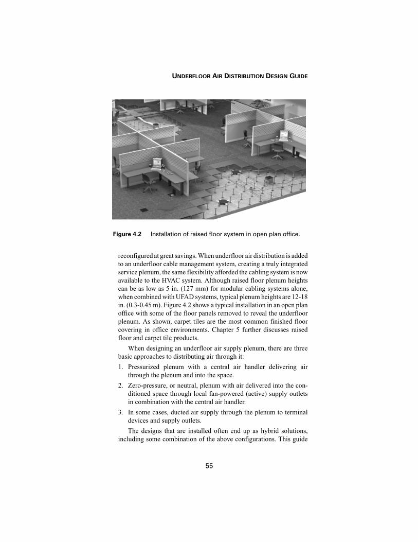
UNDERFLOOR AIR DISTRIBUTION DESIGN GUIDE
55
reconfigured at great savings. When underfloor air distribution is addedto an underfloor cable management system, creating a truly integratedservice plenum, the same flexibility afforded the cabling system is nowavailable to the HVAC system. Although raised floor plenum heightscan be as low as 5 in. (127 mm) for modular cabling systems alone,when combined with UFAD systems, typical plenum heights are 12-18in. (0.3-0.45 m). Figure 4.2 shows a typical installation in an open planoffice with some of the floor panels removed to reveal the underfloorplenum. As shown, carpet tiles are the most common finished floorcovering in office environments. Chapter 5 further discusses raisedfloor and carpet tile products.
When designing an underfloor air supply plenum, there are threebasic approaches to distributing air through it:
1. Pressurized plenum with a central air handler delivering air
through the plenum and into the space.
2. Zero-pressure, or neutral, plenum with air delivered into the con-
ditioned space through local fan-powered (active) supply outlets
in combination with the central air handler.
3. In some cases, ducted air supply through the plenum to terminal
devices and supply outlets.
The designs that are installed often end up as hybrid solutions,including some combination of the above configurations. This guide
Figure 4.2 Installation of raised floor system in open plan office.

CHAPTER 4—UNDERFLOOR AIR SUPPLY PLENUMS
56
will focus on the first two approaches, as guidelines for fully ducted airdistribution systems are well established.
4.1.1 Pressurized Plenum
In pressurized plenums, the central air-handling unit (AHU) is con-trolled to maintain a small, but positive pressure in the underfloor ple-num relative to the conditioned space. Typical plenum pressures fall inthe range of 0.05 - 0.1 in. H2O (12.5 - 25 Pa). To date, pressurized ple-nums have been the most commonly installed UFAD configuration. Inmost practical situations, pressurized plenums can maintain a very con-stant plenum pressure across a single control zone [Bauman et al.1999a]. This allows any passive diffuser of the same size and controlsetting (typical damper opening) located in the zone to deliver the sameamount of air to the space. However, airflow performance can beimpacted by uncontrolled air leakage and when floor panels areremoved for access to the underfloor plenum. See Sections 4.2 and 4.3for further discussion.
When the supply air flows freely through the underfloor plenum,heat exchange with the structural mass (concrete slab and raised floorpanels) may influence supply temperature variations as a function ofdistance traveled through the plenum, as well as other thermal perfor-mance issues. These are discussed in Section 4.4.
4.1.2 Zero-Pressure Plenum
In zero-pressure plenums, the central AHU delivers conditioned airto the underfloor plenum in much the same manner as with pressurizedplenums, but in this case, the plenum is maintained at very nearly thesame pressure as the conditioned space. Local fan-powered (active)supply outlets are required to supply the air into the occupied zone ofthe space. To date, several zero-pressure plenum designs have beeninstalled, but they have not enjoyed the same amount of market pene-tration as pressurized systems.
In terms of airflow performance, fan-powered outlets provideimproved control of the supply airflow rate compared to passive dif-fusers. Active diffusers are well-suited for task/ambient conditioning(TAC) system applications in which occupant control is a key designobjective. The removal of floor panels in zero-pressure plenums willnot impact airflow performance. Similarly, zero-pressure plenums poseno risk of uncontrolled air leakage to the conditioned space, adjacentzones, or outside.
The advantages of no leakage and improved local airflow controlmust be traded off against several factors. Fan-powered supply outlets

UNDERFLOOR AIR DISTRIBUTION DESIGN GUIDE
57
may have a cost premium compared to passive diffusers used in pres-surized plenum designs. In terms of energy use, although central fanenergy consumption will be reduced compared to that for a pressurizedplenum, this savings will be offset by the energy consumed by the largenumber of small local fans. However, if a pressurized plenum leaks ata high rate, this can also lead to excessive fan energy use. Another con-sideration with local fan-driven units is the possibility of increasednoise levels, although underfloor systems are generally rated as beingquieter than conventional overhead systems.
Zero-pressure plenums share many of the same thermal perfor-mance issues as pressurized plenums. See Section 4.4 for further dis-cussion.
4.2 AIRFLOW PERFORMANCE IN PRESSURIZED PLENUMS
A series of experiments [Bauman et al. 1999a] were conducted ina full-scale (3,200 ft2 [300 m2]) pressurized underfloor plenum testfacility to assist in the development of design guidelines for acceptableairflow performance, plenum size, plenum inlets, and the effects ofobstructions (i.e., cables, ductwork, equipment) within the floor cavity.Results of these tests are presented in the subsequent sections.
4.2.1 Dimensional Constraints of the Plenum
One of the objectives of the aforementioned study was to identifythe minimum plenum height at which acceptable air distributionthroughout the plenum could be expected. Tests (see Figures 4.3 and4.4) performed on plenums varying from 3 in. (75 mm) to 8 in. (205mm) in height indicate that good distribution within the plenum can beachieved with plenum heights as low as 4 in. (100 mm). However, low-height plenums (approaching 4 in. [100 mm] deep or lower) should belimited to applications where space airflow requirements do not exceed1 cfm/ft2 (5.1 L/(s·m2)), as outlet distribution variances in excess of±10% were experienced. In the figures, airflow data are presented interms of “delivered airflow ratio” vs. distance from the plenum (fan)inlet, which was located at one end of the plenum. The delivered airflowratio is defined as the measured airflow normalized by the amount ofairflow that would be delivered if it were uniformly distributed acrossthe plenum. In other words, a perfectly uniform distribution of air deliv-ery through all floor outlets would yield a “delivered airflow ratio” of100% at all distances from the inlet.
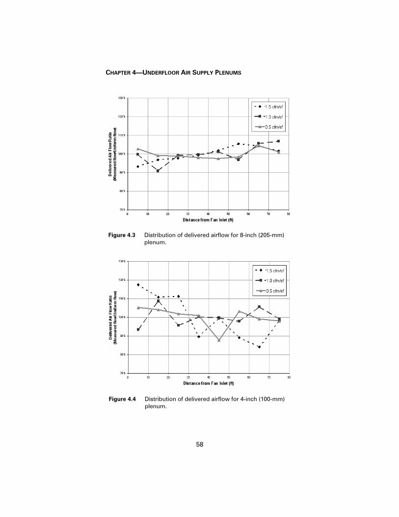
CHAPTER 4—UNDERFLOOR AIR SUPPLY PLENUMS
58
Figure 4.3 Distribution of delivered airflow for 8-inch (205-mm)plenum.
Figure 4.4 Distribution of delivered airflow for 4-inch (100-mm) plenum.

UNDERFLOOR AIR DISTRIBUTION DESIGN GUIDE
59
The maximum footprint of the plenum can be determined in rela-tion to the feasible number (and size) of inlet locations. Plenum inletsizes and locations are discussed in the following sections.
4.2.2 Plenum Inlets
The maximum practical distance between the point where condi-tioned air is injected into the open underfloor plenum and its point ofdischarge into the space is generally determined by:1. The degree of thermal decay experienced by the air as it moves to
the supply outlet.
2. The residence time of the conditioned air within the open floor
cavity.
While resident within the underfloor plenum, the conditioned air issubject to heat transfer from the building slab, as well as the room (bymeans of the raised floor panels). This thermal transfer rate, discussedin greater detail in Section 4.4, generally limits the distance throughwhich the conditioned air may travel according to its maximum allow-able temperature rise. Although additional research is needed in thisarea, designers familiar with underfloor system design typicallyemploy as a guideline a 0.05-0.15°F temperature gain per linear foot oftravel (0.1-0.3°C/m), resulting in a maximum practical distance of 50-60 ft (15-18 m) between the plenum inlet and point of discharge into thespace.
4.2.3 Horizontal Ducting within the Plenum
Horizontal ductwork and air highways (discussed in greater detailin Section 4.4.2) may be used to bridge the distance between the pointof injection into the plenum and the farthest supply outlet. If employed,the velocities in these conduits should be limited to a maximum of1,200-1,500 fpm (6-7.5 m/s). Outlets can be located along the length ofthe duct (or air highway) to optimally allocate the air within the ple-num. The discharge velocity through these smaller outlets should, how-ever, be limited to 800-1,000 fpm (4-5 m/s). The placement ofbalancing dampers in these discharge outlets should also be consideredto avoid variances in the plenum distribution.
4.2.4 Obstructions within the Plenum
Tests with obstructions located within the plenum airflow indicatedthat acceptable airflow performance (static pressure variations of±10% or less) was experienced as long as a 3-in. (75-mm) clear spacewas maintained perpendicular to the airflow through the plenum (seeFigure 4.5).

CHAPTER 4—UNDERFLOOR AIR SUPPLY PLENUMS
60
4.3 AIR LEAKAGE
While air leakage is not an issue for zero-pressure plenum designs,evidence from completed projects using pressurized plenums indicatesthat uncontrolled air leakage from the plenum can impair system per-formance [Daly 2002]. If this leakage occurs across the building enve-lope it will directly impact energy use. If the leakage occurs within thebuilding it may or may not impact energy use depending on where theleakage takes place. In any case, it is highly recommended to minimizeleakage from the plenum and, when it is unavoidable, to account forthe leakage airflow rate in the operation of the system, as discussedfurther below.
There are two primary types of uncontrolled air leakage from apressurized underfloor plenum: (1) leakage due to poor sealing or con-struction quality of the plenum and (2) leakage between floor panels.A third type of leakage occurs when floor panels are removed for accessto the plenum, but this is usually temporary.
4.3.1 Leakage Due to Construction Quality
It is important that proper attention be given to the sealing of edgedetails all around the underfloor plenum, including window-wall con-
Figure 4.5 Distribution of delivered airflow for different obstruc-tions in 8-inch (205-mm) plenum (1.5 cfm/ft2 [7.6 L/(s·m2)]).
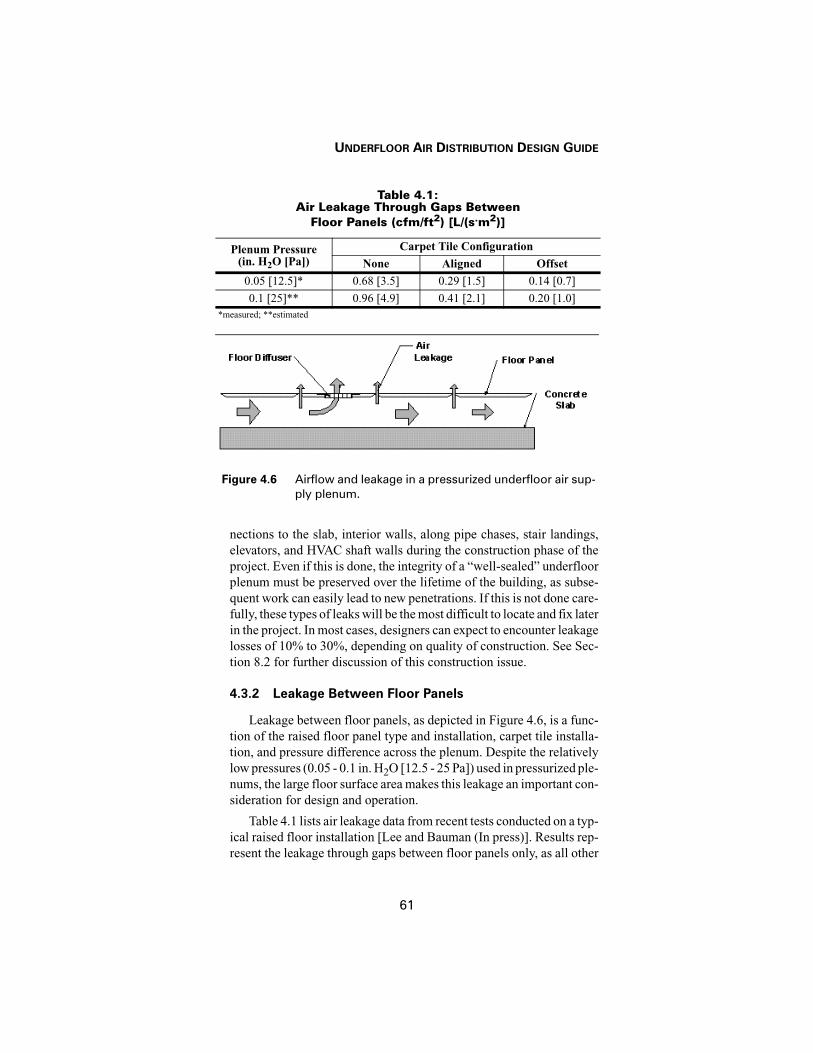
UNDERFLOOR AIR DISTRIBUTION DESIGN GUIDE
61
nections to the slab, interior walls, along pipe chases, stair landings,elevators, and HVAC shaft walls during the construction phase of theproject. Even if this is done, the integrity of a “well-sealed” underfloorplenum must be preserved over the lifetime of the building, as subse-quent work can easily lead to new penetrations. If this is not done care-fully, these types of leaks will be the most difficult to locate and fix laterin the project. In most cases, designers can expect to encounter leakagelosses of 10% to 30%, depending on quality of construction. See Sec-tion 8.2 for further discussion of this construction issue.
4.3.2 Leakage Between Floor Panels
Leakage between floor panels, as depicted in Figure 4.6, is a func-tion of the raised floor panel type and installation, carpet tile installa-tion, and pressure difference across the plenum. Despite the relativelylow pressures (0.05 - 0.1 in. H2O [12.5 - 25 Pa]) used in pressurized ple-nums, the large floor surface area makes this leakage an important con-sideration for design and operation.
Table 4.1 lists air leakage data from recent tests conducted on a typ-ical raised floor installation [Lee and Bauman (In press)]. Results rep-resent the leakage through gaps between floor panels only, as all other
Table 4.1: Air Leakage Through Gaps Between
Floor Panels (cfm/ft2) [L/(s.m2)]
Plenum Pressure (in. H2O [Pa])
Carpet Tile Configuration
None Aligned Offset
0.05 [12.5]* 0.68 [3.5] 0.29 [1.5] 0.14 [0.7]
0.1 [25]** 0.96 [4.9] 0.41 [2.1] 0.20 [1.0]*measured; **estimated
Figure 4.6 Airflow and leakage in a pressurized underfloor air sup-ply plenum.

CHAPTER 4—UNDERFLOOR AIR SUPPLY PLENUMS
62
gaps in the plenum were sealed during the tests. Measured data areshown for a plenum pressure of 0.05 in. H2O (12.5 Pa) and for three dif-ferent modes of floor covering: none (bare floor panels), aligned carpettiles, and offset carpet tiles. No adhesive was used to install the carpettiles during these tests so reported leakage values will be slightly con-servative. As shown in Figure 4.7, aligned carpet tiles occur when thesize and edges of the carpet tile match those of the floor panel (2 ft ×2 ft [0.6 m × 0.6 m]). Offset carpet tiles occur when the carpet tile isshifted over so that the edges are not aligned. The floor panels testedrepresent a design that is known to have the lowest leakage of mostcommercially available models. Experiments have shown that air leak-age will vary approximately as the square root of plenum pressure[ASTM 2000]. Based on this relationship, the air leakage values for aplenum pressure of 0.1 in. H2O (25 Pa) can be estimated and are listedin Table 4.1. Please refer to manufacturer’s test data for more precisedata on air leakage rates for specific raised floor configurations.
The magnitude of air leakage from a pressurized plenum shown inTable 4.1 is surprisingly high. The results indicate that the layer of car-peting plays an important role by significantly reducing air leakagerates between floor panels. The performance of a UFAD system withbare floor panels would be severely compromised if no additionalmeans of sealing between panels were installed. Placing carpet tilesacross the gaps between floor panels (offset mode) reduces the air leak-age rate by 50% compared to aligned carpet tiles. Even with carpetingin place, the results suggest that minimizing leakage from other partsof the underfloor plenum should have a high priority.
Figure 4.7 Two different modes of carpet tile installation on raisedfloor panels: aligned (left) and offset (right). White linesindicate the floor panel edges.

UNDERFLOOR AIR DISTRIBUTION DESIGN GUIDE
63
4.4 THERMAL PERFORMANCE
Thermal processes within the underfloor plenum and the surround-ing thermal mass are known to have an important impact on the effec-tiveness of the plenum as part of the building’s air distribution system.These processes include (1) heat transfer between the slab and the ple-num air, (2) heat transfer between the floor panels and the plenum air,(3) variations in plenum air temperature with distance traveled throughthe plenum, and (4) thermal storage performance of the slab and floorpanels. While the delivery of an adequate amount of air through the ple-num can be quite reliable, it is more difficult to predict the thermal per-formance of underfloor plenums. Ongoing research is aimed atdeveloping a thermal model for underfloor plenums as part of a whole-building energy simulation code [Bauman et al. 2000a]. Additionalwork is needed to develop design tools for practicing engineers.
4.4.1 Thermal Decay
An important design consideration is to limit the amount of varia-tion in supply air temperature, often referred to as thermal decay, toacceptable levels for diffusers that are located farther away from theplenum inlet. Figure 4.8 shows a schematic diagram of the most com-monly occurring form of thermal decay in underfloor plenums. In cool-ing operation, cool supply air enters the plenum on the left. As it travelsthrough the plenum it is warmed by heat transfer from the floor panelson the top (heat conducted from the room) and from the concrete slabon the bottom (heat conducted from the return air plenum for the floorbelow).
Based on ongoing research [Bauman et al. 2000a], simplified ther-mal modeling [York International 1999], and the results of field mea-surements [Fukao et al. 2002], current estimates for the range ofexpected temperature increase with distance traveled through the ple-num (for typical slab temperatures and airflow rates) are approximately
Figure 4.8 Thermal decay in an underfloor air supply plenum.

CHAPTER 4—UNDERFLOOR AIR SUPPLY PLENUMS
64
0.05-0.15°F/ft (0.1-0.3°C/m). Applying this estimate in practice iscomplicated by several variables, including the following: (1) the factthat the air may not travel in a straight line between the plenum inlet andthe diffuser, (2) the number and location of plenum inlets employed, (3)the temperature difference between the plenum air and the slab andfloor panels, and (4) the existence of return air directly entering theunderfloor plenum. These are discussed briefly below.
The example shown in Figure 4.9 indicates that it is possible to cre-ate an overall airflow pattern through the plenum zone that increasesthe distance and length of time that the air travels through the plenumbefore reaching some of the diffusers. Installing plenum inlet vanes tomore uniformly spread the airflow across the full width of the plenumcould be a simple solution if temperature measurements at different dif-fusers in the zone indicate that this is a problem. Adding additional ple-num inlets or an air highway (see Section 4.2.3) is another approach forimproving the thermal uniformity of the airflow distribution within theplenum. However, this must be traded off against the available accesspoints for plenum inlets and the additional cost of the required duct-work.
The amount of heat transferred through the floor panels and slabwill have a direct impact on thermal decay in the underfloor plenum.
Figure 4.9 Plan view of plenum airflow patterns: (a) without inletvanes, (b) with inlet vanes.

UNDERFLOOR AIR DISTRIBUTION DESIGN GUIDE
65
Recent laboratory experiments report heat transfer rates through a typ-ical raised floor with carpet tiles in the range of 0.6-1.2 W/ft2 (6.4-13W/m2) [Webster et al. 2002a]. Since room and plenum air temperaturesare controlled, this floor heat transfer will remove heat from the room,thereby reducing the zone airflow requirements. As the heat is trans-ferred to the supply air, it will still appear as a load at the system level.
The heat transfer contribution through the concrete slab can be ofsimilar magnitude to the floor heat transfer rate. Warm return air flow-ing along the underside of the slab structure on the next floor down willbe the main source of heat driving this heat transfer process. Where heatloads are high and the room air is allowed to stratify, the resulting ele-vated return air temperatures will increase the load on the slab above.On the other hand, on ground floors with slabs-on-grade, single-storybuildings, and lightly loaded buildings, heat transfer through the slabwill be correspondingly reduced.
Conductive heat gain from sunlit facades is another potential con-tributor to thermal decay. Large amounts of heat collected by the build-ing skin and transferred to the directly coupled building slab can resultin a significant rise in adjacent plenum air temperatures. In practice,plenum air temperature decays of as much as 10°F (6°C) have beenobserved in the outer 4 ft (1.2 m) of the plenum near these sunlit walls.As such, direct routing of plenum supply air through diffusers withina few feet (less than 1 m) of such facades is discouraged. The employ-ment of fan-assisted (cooling) terminals discharging into a common(insulated) duct minimizes this problem by (1) drawing the supply airfrom several feet (~2 m) inside the plenum and (2) insulating the dis-charged air from the floor slab and warm façade. Chapter 9 discussesthe advantages and liabilities of various control strategies for perimeterspaces.
In some plenum configurations, return air may directly enter theplenum without being ducted back to the AHU where it can be easilymixed with the primary supply air. The most typical pathway for thisto happen is in zero-pressure plenums with active diffusers, whereroom air may enter through passive equalizing floor grilles, when air-flow demand at the fan-powered outlets exceeds the primary air quan-tity entering the plenum, creating a slightly negative-pressure plenum.In pressurized plenums, it is unlikely that room air will reenter the ple-num through passive diffusers. If this occurs, the major concern is theimpact of the warm return air on supply temperatures. The net effectmay be unexpectedly high supply air temperatures, giving the impres-sion that thermal decay is severe, when in fact the source of the tem-perature rise is the unmixed return air entering the plenum.

CHAPTER 4—UNDERFLOOR AIR SUPPLY PLENUMS
66
It is difficult to predict the impact that the various factors describedabove have on thermal decay in an underfloor plenum. To date, mostdesigners with experience in UFAD design are using a rule-of-thumblimiting the maximum distance from the plenum inlet to the farthestdiffuser to about 50-60 ft (15-18 m) in pressurized plenum designs. Inzero-pressure plenum configurations with return air recirculatingdirectly into the underfloor plenum, a previously used solution is todeliver the primary air at more frequently spaced intervals throughoutthe plenum. Shute (1995) recommends distribution intervals for thissituation of no greater than 30 ft (9 m).
Nighttime precooling of the thermal mass in the plenum can alsopartially offset some of the thermal decay by allowing higher plenuminlet temperatures to be used. As illustrated in Figure 4.10, when theexposed thermal mass in the plenum has been cooled to a lower tem-perature, the magnitude of the thermal decay will be reduced (compareto Figure 4.8). If properly implemented, this thermal storage controlstrategy allows the building to act as a fly wheel during daytime coolingperiods, thereby saving energy and reducing energy costs (Section 7.5).
4.4.2 Ductwork and Air Highways
The use of ductwork and air highways to distribute supply airthrough parts of the underfloor plenum is another common method forcontrolling temperature variations in the plenum. In fact, early UFADdesigns tended to be very conservative and resembled ducted overheadair distribution systems placed under the floor. These early designs fea-tured a considerable amount of ductwork delivering air to temperaturecontrol zones that were defined by underfloor partitions. This approachmade the thermal performance of the UFAD system easier to predictbut cluttered up the plenum with ducts, partitions, and other HVACequipment. In recent years, it has become recognized increasingly that
Figure 4.10 Reduced thermal decay in an underfloor air supply ple-num with pre-cooled thermal mass.

UNDERFLOOR AIR DISTRIBUTION DESIGN GUIDE
67
it is desirable to the extent possible to minimize the amount of installedducts, air highways, and other HVAC-related components. The result-ing open plenum can more easily serve as a highly flexible and acces-sible service plenum.
While ductwork can isolate airflow from the thermal decaydescribed in Section 4.4.1, air highways can still be influenced by heattransfer from both the slab and floor panels. Although no research todate has addressed this issue, designers should be aware that thermaldecay may occur in long runs of air highways.


69
Chapter 5Underfloor Air Distribution (UFAD)Equipment
Due to growing interest in UFAD systems in the U.S., several newproducts have been introduced in recent years and this trend is expectedto continue. In this section we briefly describe some of the productscurrently available, including both UFAD and TAC diffusers, under-floor fan terminals, and raised floor systems. Not all products areincluded as this is intended to provide an overview of the range andtypes of equipment obtainable. Product listings are provided for infor-mation only and do not constitute a recommendation or endorsement.Another recent review of UFAD and TAC equipment is provided byLoftness et al. [2002]. It is recommended that you contact the equip-ment manufacturers directly to obtain the most up-to-date productinformation.
5.1 SUPPLY UNITS AND OUTLETS
5.1.1 Types of UFAD and TAC Diffusers
Figure 5.1 is a schematic diagram showing five possible locationsand types of supply diffusers that can be located within a typical work-station. All diffusers that are positioned near an occupant’s work loca-tion should be controllable to some extent by the occupant. The mostcommon occupant controls are velocity (volume) and/or supply airdirection. Floor diffusers are installed as part of a standard UFAD sys-tem. As shown in Figure 5.1, diffuser #1 is a round swirl floor diffuserand #2 is a rectangular jet floor diffuser. Other floor diffusers are avail-able as discussed further below. The most effective TAC diffusers arelocal fan-driven, jet-type diffusers that are located on the furniture inclose proximity to the occupant. This configuration makes their con-trols easily accessible, allowing occupants to optimize their personal

CHAPTER 5—UNDERFLOOR AIR DISTRIBUTION (UFAD) EQUIPMENT
70
comfort by controlling the quantity of air supply being directed towardthem. In Figure 5.1, diffuser #3 is a desktop diffuser, #4 is an underdeskdiffuser, and #5 is a partition-based diffuser. Refer to Chapter 3 for per-formance data on effective cooling rates for three different TAC dif-fusers.
In all areas outside of workstations, the same floor diffusers shownin Figure 5.1 can also be used. Most manufacturers provide both pas-sive and active diffusers. Passive diffusers are defined as air supply out-lets that rely on a pressurized underfloor plenum to deliver air from theplenum through the diffuser into the conditioned space of the building.Active diffusers are defined as air supply outlets that rely on a local fanto deliver air from either a zero-pressure or pressurized plenum throughthe diffuser into the conditioned space of the building. Diffusers can beconfigured as constant air volume (CAV) or variable air volume (VAV).Although most diffusers have some form of manual control of supplyvolume (by controlling a damper), only those that provide automaticadjustment of the supply volume can be classified as true VAV diffus-ers. Additionally, in perimeter zone applications where automatic con-trol is needed to respond to rapidly changing loads, linear floor grilles
Figure 5.1 UFAD and TAC diffuser locations in a workstation.

UNDERFLOOR AIR DISTRIBUTION DESIGN GUIDE
71
are frequently installed, typically ducted from a fan-coil unit to providecooling and heating when needed.
Several ceiling-mounted supply outlets that allow some amount ofpersonal adjustment have also been developed, but these are notincluded in this design guide. Please refer to Loftness et al. [2002] forinformation on these products.
5.1.2 Passive Swirl Floor Diffusers
Figures 5.2–5.4 show four different passive swirl diffuser designsthat are commonly installed in UFAD systems. More models are avail-able for this than for any other type of diffuser. The swirling airflow pat-tern of air discharged from this round floor diffuser provides rapidmixing of supply air with the room air up to the height of the verticalthrow of the diffuser. Although the discharge pattern for most swirl dif-fusers is not adjustable, nearby occupants have limited control of theamount of air being delivered by rotating the face of the diffuser (Fig-ures 5.2 and 5.3) or by opening the diffuser and adjusting a volume con-trol damper (Figure 5.4). Different models and sizes are available, butthe maximum flow rate for passive swirl diffusers operated at typicalunderfloor plenum pressures is 90-100 cfm (40-47 L/s) at 0.08 in. H2O(20 Pa). Most models are equipped with a catch basin for dirt and liquidspills. Figure 5.4 shows the various components that are assembled toinstall a complete floor diffuser. Grilles are supported in the predrilled
Figure 5.2 Cutaway photo of passive swirl floor diffuser [Trox 2002].

CHAPTER 5—UNDERFLOOR AIR DISTRIBUTION (UFAD) EQUIPMENT
72
Figure 5.3 Passive swirl floor diffuser [Nailor 2002].
Figure 5.4 Passive swirl floor diffusers [Price 2002].

UNDERFLOOR AIR DISTRIBUTION DESIGN GUIDE
73
hole through the carpet tile and raised floor panel with a trim ring ontop and a retainer, or mounting ring, below. Two grille designs areshown in Figure 5.4. The one on the right with radial slots produces thestandard swirl discharge pattern. The two on the left feature a combi-nation grille with part (radial slots) producing the same swirl dischargepattern and part (circular slots) producing more of an inclined jet dis-charge pattern. The directional characteristics of the jet discharge allowan occupant to control the amount of air blowing toward them (forincreased cooling) or away from them by rotating the grille.
5.1.3 Passive VAV Floor Diffusers
Figure 5.5 shows a variable-area diffuser that is designed for VAVoperation. It uses an automatic or manual internal damper to adjust theactive area of the diffuser in order to maintain a nearly constant dis-charge velocity, even at reduced supply air volumes. At maximum flow,the diffuser is designed to deliver 150 cfm (71 L/s) at a plenum pressureof 0.05 in. H2O (12.5 Pa). This passive diffuser does not require a localfan, but 24-volt power is needed for the thermostatically controlleddamper motor. Air is supplied through a slotted square floor grill in ajet-type airflow pattern. Occupants can adjust the direction of the sup-ply jets by changing the orientation of the grille. Supply volume is con-trolled by a thermostat on a zone basis or as adjusted by an individualuser.
Figures 5.6 and 5.7 present two different approaches for convertingswirl diffusers to VAV diffusers. Both require control power to auto-
Figure 5.5 Passive variable-area (VAV) diffuser [York 2002].

CHAPTER 5—UNDERFLOOR AIR DISTRIBUTION (UFAD) EQUIPMENT
74
Figure 5.6 Passive VAV swirl diffuser [Trox 2002].
Figure 5.7 VAV floor boot for swirl diffuser [Price 2002].

UNDERFLOOR AIR DISTRIBUTION DESIGN GUIDE
75
matically adjust a volume control damper. In Figure 5.6, which is thesame grille as Figure 5.2, the circular damper is raised and lowered tochange the height of the opening for air to enter from a pressurized ple-num. Figure 5.7 is a floor boot that is designed to be mounted on theunderside of a raised floor panel containing a round swirl diffuser. Theround control damper located in the inlet can be rotated over a range of90° to adjust the inlet opening from fully open to fully closed. Supplyair either enters the boot directly from a pressurized plenum or can beducted from a fan-powered terminal unit.
5.1.4 Linear Floor Grilles
Linear grilles have been used for many years, particularly in com-puter room applications. Air is supplied in a jet-type planar sheet, mak-ing them well matched for placement in perimeter zones adjacent toexterior windows (Figure 5.8). Although linear grilles may be config-ured as passive diffusers in a pressurized plenum, care should be exer-cised to prevent heat transfer from the building façade to the slab when
Figure 5.8 Placement of linear grilles along exterior glazing inperimeter zones.

CHAPTER 5—UNDERFLOOR AIR DISTRIBUTION (UFAD) EQUIPMENT
76
Figure 5.9 Photo and schematic of linear floor grille with VAV cool-ing and CAV heating (Price 2002).

UNDERFLOOR AIR DISTRIBUTION DESIGN GUIDE
77
using them in perimeter zones (see Section 4.4.1). Instead, perimeterzone applications should involve ducting the grilles from fan coil unitsor some other means of minimizing heat gain from the slab and warmfaçade. Linear grilles typically have multi-blade dampers that are notdesigned for frequent adjustment by individuals and are therefore notused in densely occupied office space where some amount of occupantcontrol is desirable.
Figure 5.9 shows a recently introduced linear floor grille for perim-eter zone applications. The heating inlet (shown) is designed for ductedfan-powered supply air when there is a call for heating. The inlet alsofeatures a backdraft damper to prevent air supply when the fan is turnedoff. On the opposite side of the unit (not shown) is the cooling inlet.Cooling air supply is delivered directly from a pressurized plenum andis modulated in VAV mode by a control damper. The control dampercloses down to the minimum opening on a call for heating. Controlpower is required for the VAV operation of the unit. The unit deliversup to 200 cfm (94 L/s) at 0.1 in. H2O (25 Pa).
5.1.5 Active TAC Diffusers
Figure 5.10 shows a TAC supply unit that features two desktop airsupply pedestals, which are fully adjustable for airflow direction, aswell as air supply volume by adjusting a control panel on the desk. Air
Figure 5.10 Desktop TAC supply unit [Johnson Controls 2002].

CHAPTER 5—UNDERFLOOR AIR DISTRIBUTION (UFAD) EQUIPMENT
78
is supplied from a mixing box that is hung in the back or corner of theknee space of the desk and connected to the two desktop supply noz-zles. The mixing box uses a small variable-speed fan to pull air from theunderfloor plenum and deliver a free-jet-type airflow from the nozzles.The unit can supply a total of 12-150 cfm (6-70 L/s) through its twonozzles. See Chapter 3 for occupant cooling performance data for thisdiffuser. Recirculated air is also drawn from the knee space through amechanical prefilter. Both primary supply air and recirculated room airare drawn through an electrostatic air filter. As shown in Figure 5.11,the unit has a desktop control panel containing adjustable sliders thatallow the occupant to control the speed of the air emerging from thenozzles, its temperature, the temperature of a 200-watt radiant heatingpanel located in the knee space, the dimming of the occupant’s tasklight, and a white noise generator for acoustical masking. The controlpanel also contains an infrared occupancy sensor that shuts the unit offwhen the workstation has been unoccupied for a few minutes.
Figure 5.12 shows an active (fan-driven) underdesk TAC diffuserconsisting of a panel attached to the underside of a conventional desk,connected by a flexible duct to a portable filter and fan unit placed nextto the desk (shown) or in the underfloor plenum. Airflow from twoadjustable outlets at the front edge of the desk is used to condition the
Figure 5.11 The occupant can control local environmental condi-tions using a desktop control panel [Johnson Controls2002].

UNDERFLOOR AIR DISTRIBUTION DESIGN GUIDE
79
occupant’s local workspace. One of the supply outlets delivers supplyair directly upward into the occupant’s breathing zone. The other deliv-ers air toward the occupant’s body for cooling purposes. The maximumairflow from the unit is only 15 cfm (7 L/s) because the air is concen-trated directly on the occupant. Heating of the lower part of the bodycan be provided by a controllable radiant heating panel under the desk.
Figure 5.13 shows a schematic diagram of another active (fan-driven) underdesk TAC diffuser consisting of five 4-way adjustablegrilles, similar to a car's dashboard. A fan unit located in the underfloorplenum delivers air through a flexible duct to two outlet locations: (1)the supply grilles (jet-type) mounted just below and even with the frontedge of the desk, and (2) in this example, a supply grille located on thebackside of the desk. This configuration permits a true task/ambientcontrol strategy to be employed. The total air supply delivered to bothsupply outlets is thermostatically controlled to maintain overall com-fort conditions in the ambient space. The amount of air suppliedthrough the underdesk diffuser can be adjusted by occupants using adamper lever just behind the supply grilles to satisfy their personalcomfort preferences. The underdesk diffuser is nominally designed todeliver 0-70 cfm (0-33 L/s) of supply air. See Chapter 3 for occupantcooling performance data for this diffuser. Other configurations usingthis same TAC control strategy are available (Figure 5.14).
Figure 5.12 Underdesk TAC supply unit [Johnson Controls 2002].

CHAPTER 5—UNDERFLOOR AIR DISTRIBUTION (UFAD) EQUIPMENT
80
Figure 5.13 Underdesk TAC supply unit [Argon Corporation 2002].
Figure 5.14 Alternative TAC supply outlet configurations [Argon Cor-poration 2002].

UNDERFLOOR AIR DISTRIBUTION DESIGN GUIDE
81
Figure 5.15 shows an active (fan-driven) floor supply unit, consist-ing of two swirl diffusers mounted in a single raised floor panel. A wall-mounted thermostat varies the speed of the fan (as shown mounteddirectly below the floor diffusers) to control the air supply to the space.These units can deliver up to 350 cfm (170 L/s) of supply air at maxi-mum fan speed. They can also be configured with directional (jet type)diffusers that can be adjusted by the occupant to direct the airflow dis-charge.
Partition-based diffusers, mounted in the partitions immediatelyadjacent to a desk, are another TAC diffuser design. A fan unit in theunderfloor plenum delivers air through passageways that are integratedinto the partition design to controllable supply grilles (jet-type) thatmay be located just above desk level or just below the top of the panel.Although uncommon in the U.S., some of these systems have beeninstalled in Japan [Matsunawa et al. 1995].
5.2 UNDERFLOOR FAN TERMINALS
Underfloor fan terminal units are typically used in perimeter zonesand other special zones where large and rapid changes in cooling and/
Figure 5.15 Active TAC floor supply unit [Trox 2002].

CHAPTER 5—UNDERFLOOR AIR DISTRIBUTION (UFAD) EQUIPMENT
82
or heating load requirements occur. Figure 5.16 shows an example ofone such terminal unit featuring two variable-speed fans (for addedcapacity) and a hot water reheat coil. Despite the larger profile of thisunit, Figure 5.17 demonstrates how its installation, as well as a standardsingle-fan terminal unit, is compatible with the 2 ft × 2 ft (0.6 m × 0.6m) grid of raised floor support pedestals in an underfloor plenum. Theheight of fan terminals must also be considered to allow adequate clear-ance below the raised floor panels. Units with heights as low as 8 in.(200 mm), requiring only a 10-in. (250 mm) high floor, are available.In addition, fan terminal units can be configured to serve a range ofoperational needs, including constant- and variable-speed fans withheating and cooling coils.
Figure 5.18 shows a schematic diagram of one possible fan-pow-ered terminal configuration serving a perimeter zone. The terminal unitwith a hot-water or electric heating coil is used in combination with twoor more variable-area VAV diffusers (Figure 5.5) to provide both cool-ing and heating operation. During cooling mode, the fan terminal isturned off, and all diffusers operate in normal VAV mode to deliver thedesired amount of cool plenum air (full cooling is shown in Figure 5.18(a)). During heating operation, the fan terminal is activated, pullingreturn air from the room through one diffuser and supplying air to theroom through the other diffuser. Figure 5.18 (b) shows the diffuserdampers adjusted in full heating position, although an adjustable stopfor the damper can be installed to provide minimum ventilation air from
Figure 5.16 Underfloor fan terminal with two variable-speed fansand hot water reheat [Greenheck 2002].

UNDERFLOOR AIR DISTRIBUTION DESIGN GUIDE
83
Figure 5.17 Placement of single- and double-fan units betweenraised floor support pedestals [Greenheck 2002].
(a) Full cooling mode
Figure 5.18 Perimeter solution using heating fan terminal with VAVdiffusers [York 2002].
(b) Full heating mode

CHAPTER 5—UNDERFLOOR AIR DISTRIBUTION (UFAD) EQUIPMENT
84
the plenum. Under thermostatic control, room air provides the firststage of heating followed by activation and modulation of the heatingcoil. This perimeter solution requires no underfloor partitions.
Figure 5.19 shows a photo of another possible underfloor fan ter-minal installation serving a perimeter zone. The fan operates only dur-ing periods of reheat and peak cooling demand. Under normal coolingoperation, the VAV damper (on the left side of the unit) controls theamount of cooling from a pressurized plenum. The first stage of reheatoccurs by closing the VAV damper so that the main source of air is recir-culated room air entering through the floor grille at the lower left in thephoto. Ventilation air is assumed to enter the space from adjacent over-ventilated spaces. Under peak heating conditions, an integral (hot wateror electric) coil is energized. The terminal discharge at the top of thephoto enters a small partitioned plenum zone containing typically 4-6swirl diffusers (linear grilles could also be used). It is recommendedthat you contact the equipment manufacturers directly to obtain themost up-to-date information on fan terminal units and applications.Also, see Chapter 9 for further discussion of perimeter and special zonesolutions.
Figure 5.19 Perimeter zone installation of fan terminal unit with VAVcooling and reheat [Trox 2002].

UNDERFLOOR AIR DISTRIBUTION DESIGN GUIDE
85
5.3 RAISED FLOOR SYSTEMS
A raised, or access, floor system is an elevated platform constructedon another floor, typically a concrete slab in a building. In North Amer-ica, the raised floor platform is made up of 2 ft × 2 ft (0.6 m × 0.6 m)floor panels that are supported at their corners by adjustable pedestals.The installation of a raised floor system creates a convenient and acces-sible space that can be used to cost-effectively distribute many buildingservices, including power, voice, data cabling, air-conditioning, firedetection and suppression, and security. Figure 5.20 shows an exampledrawing of cable and air distribution components in an underfloor ple-num.
The majority of raised floor systems currently on the market areengineered to meet the concentrated, uniform and rolling loads expe-rienced in a typical workplace environment. For example, galvanizedsteel-encased lightweight concrete panels combine the tensile strengthof steel with the compressive strength of concrete to offer a high degreeof rigidity. The lower self weight of both lightweight concrete or steel-encased high-density particle board panels reduces deflection even fur-ther and makes removing the panels an easier process than that forequivalent standard concrete-filled panels.
High quality manufacturing processes enable panels made to verylow dimensional tolerances such as ±0.15 in. (3.8 mm). Together witha uniform panel thickness, good edge sealing, and flush-mounted floordiffusers it is possible to achieve a homogeneous floor surface overwhich loads can be distributed.
Currently the vast majority of UFAD installations in office envi-ronments use carpet tiles as the finish floor covering. The quality ofmanufactured carpet tile products has now advanced to the point whereattractive and professional installations are possible, suitable for cor-porate offices. Raised floor systems typically include floor panels and
Figure 5.20 Installation of a raised floor system creates an integratedservice plenum.

CHAPTER 5—UNDERFLOOR AIR DISTRIBUTION (UFAD) EQUIPMENT
86
carpet tiles from different manufacturers, often in different modularsizes. Floor panels are 24 in. (600 mm) square, while carpet tiles arecommonly 18 in. (450 mm), although they are also available in 24 and36 in. (600 and 900 mm). This brings up two important considerations:(1) the method of securing tiles to panels and (2) the issue of alignmentversus overlap of the floor panel and carpet tile edges.
The majority of carpet tile installations are affixed to floor panelswith adhesive (Figure 5.21). It is important to avoid using an excessiveamount of adhesive during this process as the flexibility of easyremoval of carpet tiles and access to floor panels can be compromised.Too much adhesive also risks bonding adjacent floor panels to eachother and gluing the panel screws into their corner holes, both of whichcan complicate the removal of floor panels. Should the initial carpet tiletype need to be replaced, building owners are left with an adhesive res-idue that must be removed before installation of an alternative tile sys-tem.
The above issues have the potential to diminish some of the costsavings that raised floor systems offer, as they impede flexibility andease of installation and maintenance. As an alternative, some manu-facturers offer magnetic or dimpled carpet tiles that are indexed to
Figure 5.21 Adhesive is spread on the floor panels and allowed toset up prior to laying the carpet tiles.
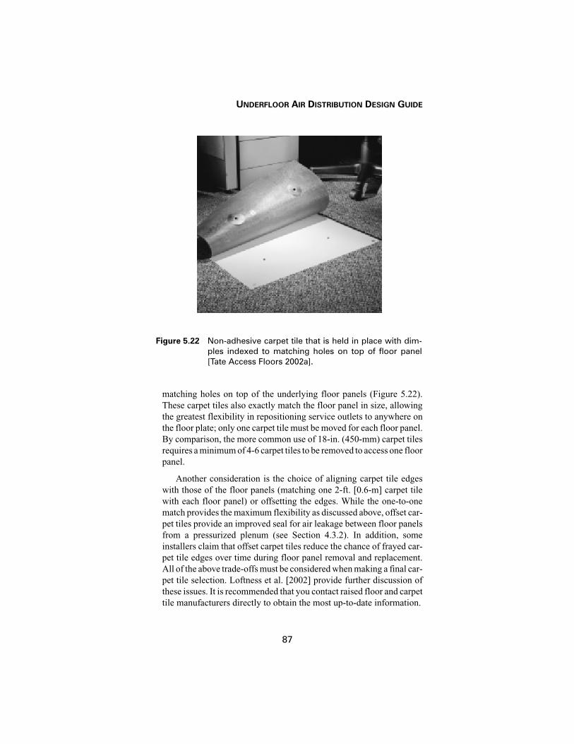
UNDERFLOOR AIR DISTRIBUTION DESIGN GUIDE
87
matching holes on top of the underlying floor panels (Figure 5.22).These carpet tiles also exactly match the floor panel in size, allowingthe greatest flexibility in repositioning service outlets to anywhere onthe floor plate; only one carpet tile must be moved for each floor panel.By comparison, the more common use of 18-in. (450-mm) carpet tilesrequires a minimum of 4-6 carpet tiles to be removed to access one floorpanel.
Another consideration is the choice of aligning carpet tile edgeswith those of the floor panels (matching one 2-ft. [0.6-m] carpet tilewith each floor panel) or offsetting the edges. While the one-to-onematch provides the maximum flexibility as discussed above, offset car-pet tiles provide an improved seal for air leakage between floor panelsfrom a pressurized plenum (see Section 4.3.2). In addition, someinstallers claim that offset carpet tiles reduce the chance of frayed car-pet tile edges over time during floor panel removal and replacement.All of the above trade-offs must be considered when making a final car-pet tile selection. Loftness et al. [2002] provide further discussion ofthese issues. It is recommended that you contact raised floor and carpettile manufacturers directly to obtain the most up-to-date information.
Figure 5.22 Non-adhesive carpet tile that is held in place with dim-ples indexed to matching holes on top of floor panel[Tate Access Floors 2002a].


89
Chapter 6Controls, Operation,and Maintenance
The control and optimization of temperatures in the occupied zoneand the amount of thermal stratification (during cooling operation) iscrucial to system design and sizing, energy-efficient operation, andcomfort performance of UFAD and TAC systems. This section presentsand discusses (1) recommended control strategies for effective systemoperation, (2) incorporation of individual control, particularly withTAC systems, to allow occupants to fine-tune their local environment,and (3) operations and maintenance (O & M) issues that differ fromissues in conventional system operation. The discussion does not coverall possible control scenarios but is intended to introduce some of thekey control strategies that have been frequently used in previously com-pleted projects and explain how they differ from those typically used inoverhead mixing-type systems.
6.1 CONTROL STRATEGIES IN PRESSURIZED PLENUMS
This section presents control strategies that have been developedand applied in underfloor air distribution (UFAD) installations, thelarge majority of which have been pressurized plenum designs.
6.1.1 Supply Air Temperature (SAT)
As described in Chapter 1, since air is supplied directly into theoccupied zone near floor level, minimum supply outlet temperaturesshould be maintained in the range of 61-65°F (16-18°C) to avoid over-cooling nearby occupants. For TAC supply outlets located closer to theoccupants and used to provide velocity cooling, even warmer minimumsupply air temperatures may be advisable.

CHAPTER 6—CONTROLS, OPERATION, AND MAINTENANCE
90
6.1.2 Constant Pressure
A common control method for interior zones maintains constantstatic pressure in the underfloor plenum to ensure constant volume air-flow from each diffuser (similar model and setting). Plenum pressureis maintained by adjusting fan capacity at the air handler. Occupantscan make minor changes to local comfort conditions by manuallyadjusting a diffuser, but such adjustments are viewed as setup adjust-ments, not operating adjustments. As long as load variations in the zonedue to diversity and other occupancy changes are small, and the netimpact on plenum pressure by occupant diffuser adjustments is mini-mal, this strategy results in very nearly a constant-air-volume (CAV)operation and can maintain acceptably comfortable space conditions.In this configuration, one strategy for controlling supply air tempera-ture that has been applied successfully in practice is to use measuredreturn air temperature as a means of maintaining stratification at thedesired level.
However, even with proper design that promotes stratification atpeak conditions, CAV operation can result in a changing environmentin the occupied region as load changes. In CAV spaces, constant supplyair temperature with decreasing load causes the space temperature pro-file to shift toward cooler temperatures and become less stratified. Inthis case, the average occupied zone temperature tends to be a fewdegrees cooler than the peak load thermostat temperature. Thus, supplyair temperature (SAT) reset is recommended. However, the systemresponse time during SAT reset can be significant due to the importantimpact of the temperature of the thermally massive concrete slab onsupply air temperatures. CAV systems become progressively moreover-aired as loads decrease from peak conditions, eventually virtuallyeliminating stratification. If the system is over-designed in the firstplace, stratification is likely never to be experienced in actual opera-tion, which may explain why many projects in operation today reportlack of stratification.
Many projects use CAV systems for large interior zones where theperimeter zones are served by supply air passing through the plenum ofthe interior zone. If these interior systems were conservatively sizedcompared to actual loads and zone airflow is not properly adjusted dur-ing system balancing, then the zone will be over-aired. As discussed inChapter 4, air leakage from pressurized plenums plus the additionalheat loss through the floor surface can provide a substantial portion ofthe required cooling under part-load conditions. If part-load conditionsor over-airing in the interior lead to a significant increase in the SAT,
UNDERFLOOR AIR DISTRIBUTION DESIGN GUIDE
91
this may compromise the system’s ability to accommodate peak perim-eter cooling loads, if they occur simultaneously. In CAV systems, inte-rior zone airflows should be well matched to actual loads; active androbust control of SAT should be employed without starving the perim-eter.
6.1.3 Variable Air Volume (VAV)
Perimeter zones typically experience load changes that are greaterin both magnitude and frequency than those encountered in interiorzones. Automatic VAV control is the preferred strategy in perimeterand special zones (e.g., conference rooms) with these rapidly changingloads. See Chapter 9 for additional discussion of perimeter and specialzone design solutions. Under VAV control, as load changes, room air-flow and diffuser flow rate will change. Recent tests indicate that VAVoperation with constant supply temperature results in a characteristicroom air stratification temperature profile that is relatively consistentfor moderate changes in load [Webster et al. 2002a].
As described above, a recent trend in perimeter zone designs inpressurized plenum installations is to have the supply air pass throughthe plenum of the interior zone to serve the perimeter. Some designersare now more frequently considering VAV control in the interior zoneas an approach to minimize over-airing (overcooling) and to avoidstarving the perimeter zone through SAT reset [Daly 2002].
6.1.4 Controlling Stratification
The objective of controlled stratification is to minimize energy use(reduce room airflow) while maintaining comfort (acceptable temper-atures and stratification in the occupied zone). Overall room air strat-ification is primarily driven by the balance of room airflow rate inrelation to the room cooling load. As discussed in Chapter 2, as roomairflow is reduced for constant heat input, stratification will increase.On the other hand, if too much air is delivered to the space, stratificationwill be reduced, approaching a well-mixed room at the upper limit.Increasing or decreasing the supply air temperature (for constant loadand room airflow) does not change the fundamental shape of the strat-ification profile but simply moves it to higher or lower temperatures.These principles are demonstrated in the example stratification controlsequence shown in Figure 6.1.
Figure 6.1 shows three different vertical temperature profiles (tem-perature (T) vs. height (H)). The profiles are not based on measureddata but rather are shown for illustration purposes only. The sequenceof moving from Profile #1 to Profile #3 is intended to demonstrate how

CHAPTER 6—CONTROLS, OPERATION, AND MAINTENANCE
92
controlling stratification in UFAD systems requires different consid-erations than for traditional overhead systems. In this example, strati-fication is controlled by adjusting airflow and SAT to achieve comfortconditions in the occupied zone for various thermostat settings. Thecooling load is assumed to be constant and at its peak value in all threecases.
Profile #1 shows a modest amount of stratification (temperaturegradient) characterized by supplying too much air to the room. As indi-cated, the temperature at the thermostat height (shown to be 60 in. [1.5m]) is TSTAT1, and the average temperature of the occupied zone(from 4 to 67 in. [0.1 to 1.7 m]) is Toz1, avg. Profile #2 represents analternative design load condition where airflow is reduced. To meet thesame thermostat control point (TSTAT1=TSTAT2) with reduced air-flow, the SAT also must be decreased. However, due to increased strat-ification, the average temperature of the occupied zone (Toz2, avg),which along with the gradient is representative of overall comfort con-ditions, has been reduced. If the SAT is increased so that the occupiedzone temperature is equivalent (Toz3, avg = Toz1, avg) to that of Profile#1, Profile #3 is produced. This simple example shows how both supply
Figure 6.1 Example sequence for controlling thermal stratification.

UNDERFLOOR AIR DISTRIBUTION DESIGN GUIDE
93
volume and SAT can be manipulated to create various occupied zonecomfort conditions for given thermostat settings. The process of mov-ing from Profile #1 to Profile #3 also demonstrates an approach thatcould be followed during commissioning to achieve the desired amountof stratification under peak load conditions.
More research is needed to more precisely define the relationshipbetween thermal comfort and stratification in UFAD systems. Whileoverhead mixing systems routinely use the thermostat temperature, itis not yet known what the optimal control temperature is for stratifiedsystems (e.g., average occupied zone temperature, weighted occupiedzone temperature taking into account the increased sensitivity at head/neck level, etc.). Readers are cautioned to use this example at their ownrisk.
ASHRAE Standard 55-92 [ASHRAE 1992] specifies that theamount of stratification in the occupied zone (temperature differencebetween head and ankle heights for a standing person) be limited to 5°F(3°C). One of the challenges of maintaining comfort in a stratified envi-ronment is that the thermostat temperature can no longer be assumedto represent the average temperature in the occupied zone. This is par-ticularly true for thermostats located at a height of 5 ft (1.5 m) near thetop of the occupied zone and therefore measuring close to the maxi-mum occupied zone temperature. Because of this, it may be necessaryto consider increasing the thermostat setpoint by up to 1-2°F [0.5-1°C]above the desired occupied zone setting under peak load conditions.The recently changed building code requiring thermostats to beinstalled at a lower 4 ft (1.2 m) height may help alleviate the need toadjust the setpoint as it will be measuring closer to an average temper-ature in the occupied zone. In any case, a balance between the amountof stratification and average, or representative, occupied zone temper-ature must be achieved within the limitations of room airflow and SATavailable from the system.
6.1.5 Humidity Control
One way to achieve the required higher supply air temperatureswhile still maintaining humidity control uses return-air face andbypass. Cooling coil temperatures are typically in the range of 50-55°F(10-13°C) for dehumidification purposes. Only the incoming outsideair and a portion of the return air is dehumidified (minimum amountneeded for humidity control). The remaining return air is bypassedaround the coil, if done at the air handler, and mixed with the cool pri-mary air to produce supply air of the proper temperature and humiditybefore being delivered directly into the underfloor plenum. The face

CHAPTER 6—CONTROLS, OPERATION, AND MAINTENANCE
94
and bypass dampers are controlled to achieve the desired supply airtemperature as load changes. To save energy, the coil temperature canbe varied to control humidity so a greater coil leaving temperature canbe used when entering humidity conditions are low. If desired, this con-figuration also allows a range of coil temperatures to be utilized,including low-temperature air systems with or without ice storage.
6.2 CONTROL STRATEGIES IN ZERO-PRESSURE PLENUMS
Although active diffusers may be installed in both zero-pressureand pressurized plenums, this section will focus on control issues asso-ciated with zero-pressure plenums with diffusers that are more likely tobe adjusted by individual occupants. For additional discussion of task/ambient conditioning (TAC) system control issues, see Bauman andArens [1996].
Control strategies for the building's central mechanical systemshould be well coordinated with the local supply outlets. Since mostTAC systems are used for cooling applications, if the general officespace is overcooled by the ambient air distribution system control strat-egy, the cool air provided by the fan-driven local supply units will beunwanted by the occupants. By allowing the overall space temperatureto rise (an energy-saving strategy), local cooling can then be used asneeded to satisfy individual comfort preferences.
Supply volume control of the central air handler requires a differentapproach with zero-pressure underfloor air distribution systems. Dueto the extremely small or nonexistent pressure differentials between thesupply plenum and the space, traditional pressure-sensing methods donot provide accurate measurements for control purposes. A CAV-VTapproach has been successfully used, but the chance of over-airing orresetting SAT too high under part-load conditions must be carefullyguarded against, as described above.
An ingenious VAV control strategy proposed by Shute [1992]addresses the need to balance the airflow delivered by the central AHUinto the plenum with the airflow leaving the plenum. The approach usesa temperature sensor in a vertical induction shaft directly connectingthe return air at ceiling level to the underfloor plenum. Under normaloperating conditions with this design, the active floor supply units willbe delivering slightly more air to the space than is provided by the cen-tral system. So in fact, the plenum will be operated at a slight negativepressure. In this case, the temperature sensor will measure normal roomreturn temperatures as the air is drawn down the induction shaft to mixwith incoming primary air. If, however, the temperature in the induc-

UNDERFLOOR AIR DISTRIBUTION DESIGN GUIDE
95
tion shaft decreases rapidly, it indicates that the demand for air supplythrough the floor supply units has been reduced (i.e., fan units havebeen turned down or off), resulting in the overpressurization of theunderfloor plenum. The central air handler can then be throttled downuntil the reversal in flow direction through the induction shaft is elim-inated. A minimum setpoint at the air handler can be used to ensure thatsufficient airflow is always supplied to the space.
Another task/ambient control strategy described in Section 5.1.5(Figures 5.13 and 5.14) allows individuals to choose the amount of airfrom an underdesk diffuser for personal comfort without influencingthe total amount of air being delivered to the space [Levy 2002]. A fanunit located in the underfloor plenum delivers air to two outlet loca-tions, one under the desk for personal control and one farther away forcontrol of the ambient space. The total air supply delivered to both sup-ply outlets is thermostatically controlled to maintain overall comfortconditions in the room. The individual controls simply divert a portionof this total air quantity to the underdesk diffuser, as desired. A CAV-VT strategy for controlling the central AHU would be the simplestapproach with this system. Of course, VAV control strategies could alsobe applied.
TAC system configurations using fan-powered supply outlets pro-vide a convenient means of allowing direct feedback from occupantcontrol actions to improve overall system operation. Advances in directdigital control systems and monitoring capabilities allow this type ofsolution to be implemented. By monitoring fan speed settings, adjust-ments can be made to the setpoints for primary supply air temperature,ambient space temperature, and central supply air volume. For exam-ple, when a large enough percentage of occupants in the same zone ofthe building select low fan speeds, indicating that they are too cool, theprimary air supply temperature to that zone could be raised.
6.3 INDIVIDUAL OUTLET CONTROLS
Due to the importance of individual controls, they should be welldesigned and convenient to use. While most floor supply units cur-rently on the market are based on manual control (requiring the user tobend down to floor level), it may be advisable to incorporate remotedesktop controls to operate the floor units; one such remote-controlledfloor unit is described by Matsunawa et al. [1995]. Local supply outletsthat are located on a desk or nearby partition provide the best config-uration for ease of use as they replicate the familiar environmental con-trol system found on the dashboard of a car. It may also be advisable

CHAPTER 6—CONTROLS, OPERATION, AND MAINTENANCE
96
to allow switching between local (individual) control and automatic(thermostatic) control as needed.
While it is well recognized that building occupants prefer individ-ual control, the extent to which they actually use the local controls, oncemade available to them, can be surprising. Several field surveys ofbuildings with operational TAC or UFAD systems have found that a rel-atively small percentage (10-20%) of the occupants make adjustmentsto their local controls on a regular basis [Hedge et al. 1992; Bauman etal. 1993, 1998; Webster et al. 2002c]. There are a number of possiblereasons for this seemingly limited use of the occupant controls. (1) Ifthe ambient space is well conditioned, there may be little need for indi-viduals to fine-tune their local environment. (2) The design of the con-trols themselves may not be optimized, making their use difficult andinconvenient. (3) Only an occasional adjustment may be customarybecause individual preferences are relatively stable. (4) The sense ofcontrol may be more important in creating comfort than the actual envi-ronmental conditions. (5) The occupants may be unaware that they areallowed to control the air supply outlet in their vicinity (either due tolack of interest by the occupant or by intention of the operations per-sonnel).
It is critical to provide clear operating instructions for the TAC sup-ply units to the occupants. Most occupants are unaccustomed to theidea of being able to control their local outlet.
6.4 OPERATION AND MAINTENANCE
As with any new building system, building operators should beproperly trained to allow the operation and control of the UFAD or TACsystem to be optimized. Experience with early projects has demon-strated that UFAD and TAC systems that are operated using traditionalcontrol strategies based on mixing air distribution system performanceare likely to have deficiencies in energy and operating costs as well ascomfort performance. In recent years, as more projects have come on-line, operating guidelines such as those described above in Sections 6.1and 6.2 are being developed that allow a wider range of system benefitsto be realized.
Among the O & M issues that may differ from those encounteredwith conventional system design are the following.
6.4.1 Cleaning Considerations in Underfloor Plenums
A common concern among occupants of buildings with UFAD sys-tems using floor grilles is that dirt and spillage will more easily enter

UNDERFLOOR AIR DISTRIBUTION DESIGN GUIDE
97
the underfloor plenum where it will mix with the air supply stream andbe distributed throughout the occupied space. Experience has shownthat if the plenum area is thoroughly cleaned at the end of construction,the amount of dust buildup on the slab is not excessive and can be han-dled through cleaning scheduled as part of normal plenum reconfigu-ration work. The required frequency of this type of cleaning isestimated to be two to three years depending on the observed rate ofbuildup. Dirt and particulates that do fall into floor diffusers will be col-lected by the catch basins beneath the diffusers. These basins should becleaned as part of the regular maintenance schedule, depending on rateof build-up.
Two important considerations are that (1) except near the plenuminlets, air speeds within the underfloor plenum are so low that they donot entrain any dirt or other contaminants from the plenum surfaces intothe supply air, and (2) if a spill or other accidental contamination, suchas fire, arises that does require cleaning, the accessibility of the under-floor plenum makes this process far simpler and more effective than inthe case of overhead ductwork.
6.4.2 Reconfiguring Building Services
As discussed in Sections 1.4.1 and 10.3.1, the improved flexibilityof raised floor systems provides significant cost savings associatedwith the reconfiguration of building services. One consideration duringthe relocation of workstations and furniture in open plan offices is thatfloor diffusers will often need to be moved (even though it is easy to doso) to accommodate the new positions of the furniture. This may actu-ally add costs compared to overhead HVAC systems, which will typi-cally not be reconfigured (at a potential cost of reduced systemperformance). Building operations staff will also need to maintain anadequate surplus stock of floor panels and carpet tiles to handle therequired reconfigurations in response to the churn rate of the buildingoccupants.
6.4.3 Acoustic Performance
Due to the elimination or minimal use of ductwork in underfloorplenums, the noise generated from the operation of a UFAD system canbe substantially less than that from a conventional ducted overhead sys-tem. This reduction in commonly found levels of background “HVAC”noise may create a situation where active sound masking or otheracoustic design measures may be required, particularly in open planoffices where lack of sound privacy is a common complaint.


99
Chapter 7Energy Use
A commonly cited benefit of UFAD systems is that they saveenergy when compared to “standard” overhead (OH) air distributionsystems. At present, this claim is difficult to prove quantitativelybecause of the lack of an energy-modeling tool that properly addressesall of the issues related to energy use with underfloor systems thatwould allow direct comparison of two simulated systems.
To help designers understand the energy impacts of UFAD, this sec-tion explains the variety of factors that affect energy use in a descriptivemanner. Topics include air distribution, economizer operation, coolingsystem efficiency, occupant thermal comfort, and pre-cooling strate-gies.
7.1 AIR DISTRIBUTION ENERGY
As described in Chapter 4, the underfloor plenum is a primary airdistribution route. Because the use of the plenum eliminates the needfor some portion of the ductwork, and because the large size of the ple-num creates little restriction to the flow of air, the amount of fan pres-sure required to deliver air in a building using UFAD can be less thanthat required in an equivalent OH system.
For example, in an OH VAV-reheat system, a typical central fandesign might provide 3 in. H2O (750 Pa) of pressure to move airthrough the index run. Typically ½ to 1 in. (125-250 Pa) of this pressuremight be required by the VAV box, reheat coil, and downstream low-pressure ductwork to the diffuser. Depending on the specific imple-mentation of an equivalent UFAD system, most of this pressure lossmight be eliminated due to the elimination of ductwork to the zones.
This chapter was contributed by Allan Daly.

CHAPTER 7—ENERGY USE
100
This reduction in pressure requirement can result in significant energysavings for a building because air distribution fans account for a largepercentage of HVAC energy demand.
However, some perimeter system designs (discussed in Chapter 9)can offset central-fan energy savings. A common approach to UFADperimeter system design employs ducted underfloor fan-powered mix-ing or VAV boxes. These fans can erode energy savings due to the inef-ficiencies inherent in small fans and motors.
In the example below (Table 7.1), two fan systems are comparedboth delivering 20,000 cfm to an example small building. In option 1,a single central fan is used. The fan is selected as an airfoil fan with a30-inch wheel. At 3 in. H2O (750 Pa) pressure, this fan uses 13.4 bhpand runs at a combined fan and motor efficiency of 70%.
In option 2, the same central fan is run at 2.5 in. H2O (623 Pa) ofpressure, and four small perimeter fans are designed to provide 0.25 in.H2O (62 Pa) of pressure and deliver 3,000 cfm (1,420 L/s) each, sim-ulating two-pipe underfloor VAV fan coils serving 60% of the total air-flow of the central fan (the remaining air is assumed to serve interiorzones). Typical of manufacturer offerings available now, these under-floor VAV fan coils are listed with electronically commutated motor(ECM) efficiencies. The small fans require 0.3 bhp each. When com-paring central fan power, Option 2 exhibits a 13% savings over Option1. When comparing total fan power, Option 2 shows a 3% savings. Thereduced pressure requirements inherent in the underfloor system makeup for the decreased efficiency of the smaller fans in this example.
For the sake of keeping this comparison simple, the same air quan-tities are used in both Option 1 simulating an overhead supply systemand Option 2 simulating a UFAD system.
This design fan power comparison does not capture the annualenergy performance of the two systems. Because the small fans handleonly the air volumes required by the varying perimeter loads, theannual energy demand of this option will depend on the degree of loadvariation and the part-load operation of both the central and perimeterfans. A valid comparison of annual energy demand between the twocases could take the form of an hour-by-hour energy simulation of thetwo systems. Such a comparison is beyond this simple analysis, andwhile the fan system models exist in computer software programs suchas DOE-2 to analyze this case, the physical performance characteristicsof zones using UFAD do not yet exist and so more detailed analysis isdifficult.

UNDERFLOOR AIR DISTRIBUTION DESIGN GUIDE
101
Table 7.1: Comparison of Fan Power for Overhead (Option 1)
vs. UFAD (Option 2) Systems
Option 1: Central Fan Only
Total Airflow 20,000 cfm
Fan Type Airfoil
Fan Wheel Size 30 in.
Design Static Pressure 3.0 in.
Motor Size 15 hp
Operating Power 13.4 bhp
Fan Efficiency 76%
Motor Efficiency 92.0%
Combined Efficiency 70%Option 2: Central Fan + 4 Perimeter Fans
Total Airflow 20,000 cfm
Fan Type Airfoil
Fan Wheel Size 30 in.
Design Static Pressure 2.5 in.
Motor Size 15 hp
Operating Power 11.7 bhp
Fan Efficiency 73%
Motor Efficiency 92.0%
Combined Efficiency 67%
Fan Airflow 3,000 cfm
Fan Type Forward Curved
Fan Wheel Size 18 in.
Design Static Pressure 0.25 in.
Motor Size 3 hp
Operating Power 0.3 bhp
Fan Efficiency 50%
Motor Efficiency 75%
Combined Efficiency 38%
Number of Units 4
Total Power 13.0 bhpComparison –3%

CHAPTER 7—ENERGY USE
102
A recent simplified analysis of central fan energy use explored theimpact of various design assumptions on the supply fan energy con-sumption for pressurized UFAD systems vs. overhead (OH) systems[Webster et al. 2000]. The study assumed that the UFAD system con-figuration allowed the entire supply air volume to be handled by thecentral air handler (no active, fan-driven outlets) and assumed a 25%reduction in fan static pressure compared to the OH system. The aver-age annual load factor for the combined core and perimeter zones wasassumed to be 65% of design load for both systems. The results showedthat the average annual fan energy savings using a VAV UFAD systemcompared to a VAV OH system (both delivering the same amount of air)was about 40%.
7.2 AIR-SIDE ECONOMIZERS
Because the operating conditions inherent in UFAD systems aredifferent from OH systems, the circumstances of when and how air-sideeconomizers can be used change from one system type to the other. Thetwo main factors that affect the use of economizers are the supply airtemperature (SAT) and the return air temperature (RAT). In general,both the SAT and RAT are higher for UFAD systems than OH systems,though the RAT elevation depends on how much stratification is devel-oped at the zone level.
For the sake of comparison, typical OH and UFAD systems will beassumed to have operating temperatures described as follows:
Both increased SAT and increased RAT extend economizer opera-tion. The increased SAT extends 100% free cooling and the increasedRAT extends integrated economizer operation.
Consider the following simple example of a single room with acooling load of 22,000 Btu/h (6,450 W) run for each of the three systemvariations described in the table above. The room setpoint is 75°F(24°C) and exfiltrates 15% of the supply air volume at the room set-point temperature (i.e., air quantity for building pressurization). InTable 7.2, each group of three lines represents UFAD with stratifica-
System Type
SAT Room Setpoint RAT
[°F] [°F] [°F]
UFAD w/stratification 65 75 85
UFAD w/o stratification 65 75 75
Overhead (OH) 55 75 75

UNDERFLOOR AIR DISTRIBUTION DESIGN GUIDE
103
Table 7.2: Comparison of Sensible Cooling Coil Energy Use
for Overhead vs. UFAD Systems
CFMsupply[ft3/min]
Qroom[Btu/h]
OAT[°F]
SAT[°F]
Qx[Btu/h]
RAT[°F]
OA%[-]
MAT[°F]
Cooling Coil ∆T
[°F]
Cooling Coil
Sensible[Btu/h]
1,180 22,000 55 65 1946 85.0 67% 65.0 0 0
2,167 22,000 55 65 3576 75.0 50% 65.0 0 0
1,084 22,000 55 55 3576 75.0 100% 55.0 0 0
1,180 22,000 64 65 1946 85.0 95% 65.0 0 0
2,167 22,000 64 65 3576 75.0 91% 65.0 0 0
1,084 22,000 64 55 3576 75.0 100% 64.0 -9 10, 729
1,180 22,000 66 65 1946 85.0 100% 66.0 -1 1, 298
2,167 22,000 66 65 3576 75.0 100% 66.0 -1 2,384
1,084 22,000 66 55 3576 75.0 100% 66.0 -11 13, 113
1,180 22,000 74 65 1946 85.0 100% 74.0 -9 11,678
2,167 22,000 74 65 3576 75.0 100% 74.0 -9 21,458
1,084 22,000 74 55 3576 75.0 100% 74.0 -19 22,650
1,180 22,000 76 65 1946 85.0 100% 76.0 -11 14,273
2,167 22,000 76 65 3576 75.0 15% 75.2 -10.2 24,200
1,084 22,000 76 55 3576 75.0 15% 75.2 -20.2 24,021
1,180 22,000 84 65 1946 85.0 100% 84.0 -19.0 24,654
2,167 22,000 84 65 3576 75.0 15% 76.4 -11.7 27,061
1,084 22,000 84 55 3576 75.0 15% 76.4 -21.7 25,452
1,180 22,000 86 65 1946 85.0 15% 85.2 -20.2 26,146
2,167 22,000 86 65 3576 75.0 15% 76.7 -11.7 27,776
1,084 22,000 86 55 3576 75.0 15% 76.7 -21.7 25,809
1,180 22,000 90 65 1946 85.0 15% 85.8 -20.8 26,925
2,167 22,000 90 65 3576 75.0 15% 77.3 -12.3 29,207
1,084 22,000 90 55 3576 75.0 15% 77.3 -22.3 26,525
1,180 22,000 96 65 1946 85.0 15% 86.7 -21.7 28,093
2,167 22,000 96 65 3576 75.0 15% 78.2 -21.7 28,093
1,084 22,000 96 55 3576 75.0 15% 78.2 -23.2 27, 598

CHAPTER 7—ENERGY USE
104
tion, UFAD without stratification, and an OH system, respectively. Fig-ure 7.1 presents these same data graphically.
Other assumptions are that the room air supply volume for theUFAD without stratification is twice the volume as for OH and isslightly more than OH for UFAD with stratification. The slight varia-tion in room air-volume requirements results from the assumption that15% of the supply air exfiltrates at the room setpoint temperature. In theUFAD case with stratification, this 15% effectively decreases theroom-air delta T and thus requires slightly more airflow to deal with theload. For the amount of stratification shown, the actual room air-vol-ume required is not known and has been assumed to be twice the OHas a simplification. This example also assumes that the climate has lowhumidity, so sensible energy is representative of relative energy per-formance. When an air-side economizer is used in a more humid cli-mate, enthalpy control is advisable.
CFM supply is the supply air volume delivered to the room. Qroom isthe room cooling load. OAT, SAT, RAT have been defined above. MATis the mixed air temperature. Q x represents the heat exfiltrated from theroom. OA% indicated the position of the outdoor air damper. CoolingCoil ∆T indicates the required sensible cooling required, and Cooling
Figure 7.1 Example of sensible cooling energy as a function of out-side air temperature.

UNDERFLOOR AIR DISTRIBUTION DESIGN GUIDE
105
Coil Sensible indicates the net sensible cooling load provided by theHVAC system.
7.2.1 Extended 100% Free Cooling
One hundred percent free cooling (meaning no cooling coil outputis required to maintain SAT, not 100% outdoor air [OA%] damper posi-tion) only happens when outdoor air temperature (OAT) is less than orequal to SAT. In the OH case, the system is on 100% free cooling upto 55°F (13°C) OAT, corresponding to the OH SAT. In the UFAD cases,100% free cooling is extended up the 65°F (18°C) OAT, correspondingto the UFAD SAT. Depending on the number of hours in the range of55-65°F (13-18°C) OAT in a given climate, this extended 100% freecooling can represent significant energy savings. In effect, the coolingcompressors simply do not have to run during these extra 100% econ-omizer hours.
7.2.2 Extended Integrated-Economizer Free Cooling
When the OAT is between a system’s SAT and RAT, then the systemcan take advantage of some free cooling, but it still needs to engage thecooling coil. This situation is called integrated economizer operationbecause the economizer and cooling coil work together in an integratedmanner to maintain the SAT downstream of the cooling coil.
As can be seen in Figure 7.1, above 55°F (13°C) and below 75°F(24°C) for the OH system, above 65°F (18°C) and below 75°F (24°C)for the UFAD non-stratified system, and above 65°F (18°C) and below85°F (29°C) for the UFAD stratified system is where integrated econ-omizer operation happens. In the UFAD cases without stratification,integrated economizer operation is not extended. In the UFAD casewith stratification the integrated economizer operation is extended to85°F (29°C).
7.2.3 Climate Factors
In the end, which effect dominates to extend economizer opera-tion—increased SAT or increased RAT—depends on OAT distributionas well as the non-stratified UFAD RAT and building load dynamics.
Another key factor that depends on climate affecting UFAD systemenergy benefits is the extent to which humidity control will drive thesystem operation. If humidity control concerns dictate that SAT mustbe low enough to dehumidify supply air, then none of the benefitsdescribed here can be captured because the SAT cannot be elevatedunless OA humidity is removed in some other manner (i.e., desiccantdehumidification).

CHAPTER 7—ENERGY USE
106
7.3 COOLING-SYSTEM EFFICIENCY
Cooling system operation at higher temperatures can reduce energyconsumption. If cooling-coil leaving air temperatures can be elevatedin UFAD systems, then the chilled water temperature serving the cool-ing coil can also be raised. In chilled water systems like this, or in DXsystems delivering warmer off-coil air temperatures, the compressor orcompressors serving the refrigerant loops will see lower lifts and con-sequently run more efficiently and use less energy.
This effect is completely dependent on the refrigerant entering andleaving the evaporator coils being warmer, thus reducing the compres-sor lift; so again, if dehumidification is needed, then this effect cannotbe captured.
7.4 OCCUPANT THERMAL COMFORT
Recent research suggests that keeping occupied zones comfortablemay be in conflict with minimizing energy use (see Section 2.3.4). Asdiscussed in Chapter 2 on room air distribution, a temperature gradientforms in the occupied zone of a space that is developing a stratifiedroom-air profile. This stratification is key to UFAD system dynamicsin that it allows the occupied zone of a room to be comfortable, but theunoccupied zone at the top of a room reaches temperatures that wouldbe uncomfortably warm.
Energy-efficient system operation relies on a well-stratified room.Unless the room-air temperature difference between the SAT and RATcan be maintained at a high level, more air will be needed to remove theload in a room, and fan energy will correspondingly increase. Forexample, using the temperatures and systems described in Section 7.2above, in the OH case a 20°F (11°C) temperature difference was devel-oped between the SAT and the RAT—75°F (24°C) RAT minus 55°F(13°C) SAT. In the UFAD case without stratification, only a 10°F (6°C)room temperature difference was developed. In this case twice as muchair is needed to remove the load. In the UFAD case with stratification,again the system was able to generate and maintain a 20°F (11°C)degree room-air temperature difference.
However, as the stratified temperature difference across a roomdevelops, so also develops a temperature difference from the bottom tothe top of the occupied zone. This occupied zone temperature gradientcan adversely affect occupant comfort. As described in Chapter 3, onlya 5°F (3°C) variation from ankle to neck is allowed by ASHRAE Stan-dard 55.

UNDERFLOOR AIR DISTRIBUTION DESIGN GUIDE
107
If a strong temperature gradient is needed for energy-efficient sys-tem operation, but that gradient generates uncomfortable conditions,then a conflict exists. Surveys and measurements in existing projectssuggest that this effect is happening to some extent, but without goodmathematical models of room-air temperature dynamics, it’s difficultto design systems that will find the best balance between comfort (lim-ited stratification) and energy (increased stratification). The determi-nation of the design cooling air quantity required to maintain comfortin UFAD systems requires a different approach from conventionaldesign methods. In addition to stratification, it can also be affected byheat loss through the raised floor and, in perimeter zones, strong con-vective plumes that may develop along the building skin. See Section12.3.1 for further discussion.
7.5 PRE-COOLING STRATEGIES
Because the slab is typically exposed to the supply-air pathways inUFAD systems, there exists an opportunity for harnessing the thermalmass of the slab in thermal storage or “pre-cooling” applications.Though this concept is elegant and offers the potential for reducedenergy costs and possibly lower cooling peak demands, it can be dif-ficult to implement and proper control requires knowledge of futureweather conditions that are obviously difficult to predict. The benefitsof this control strategy are furthermore hard to measure. To date, onlya few earlier studies of completed projects present anecdotal evidenceof the potential energy benefits of this approach [Spoormaker 1990;Shute 1995].
The concept is that, either using free-cooling or compressor coolingat off-peak energy rates, the UFAD system would circulate cool airthroughout the building, effectively removing any stored heat from thebuilding and slab and pre-cooling it for the next day. If the next dayrequires cooling from the time the system is enabled through the peakpart of the day, less cooling would need to be generated because thecool storage in the building mass could be used to deal with some of theload.
One downfall of this system is that if for some reason there is aperiod of warmup required in the morning following the nighttime pre-cooling, then the building mass would work against the heating systemand more heating energy would be required. This is why many heatingdesigns isolate the warm air supply (e.g., by ducting from a fan coilunit) from the building thermal mass.

CHAPTER 7—ENERGY USE
108
The potential benefits from this approach are real, but a provenimplementation has yet to be studied. More research is needed toaddress thermal storage performance and support the development ofdesign and implementation guidance.

109
Chapter 8Design, Construction,and Commissioning
As underfloor air distribution (UFAD) systems often represent anew approach for many contractors, it is important that members of thedesign and construction team recognize the differences from the con-ventional methods to which they are accustomed. In most projects, theimplications of the raised floor system and the creation of an underfloorair supply plenum will represent the most significant change. This sec-tion presents a number of planning, coordination, and installationissues that should be considered from the beginning of the designphase, through construction, and into occupancy, including the com-missioning process.
8.1 DESIGN PHASE
The raised access floor platform, which represents a good exampleof integrated building design, serves multiple functions. It helps createthe air supply plenum, conceals and protects cabling and other services,and provides a stable and level walking surface. The physical dimen-sions of the raised floor system should be considered early in the designprocess. These include:
• The existence of a 2 ft × 2 ft (0.6 m × 0.6 m) grid of pedestals (floorpanel supports) across all areas of the underfloor plenum (griddimensions may differ in raised floor installations outside the U.S.).
• The finished floor height of the raised floor panels above the concreteslab (typically 12-18 in. [0.3-0.45 m] from top of slab to top of floorpanel).
All members of the design team must understand the relationshipbetween these dimensions of the underfloor plenum, the size of all

CHAPTER 8—DESIGN, CONSTRUCTION, AND COMMISSIONING
110
building components that will be placed within the plenum, the place-ment and requirements for other building services not located withinthe underfloor plenum (e.g., elevators, access ramps, HVAC shafts), theoperating characteristics of the UFAD system, and the requirements fortheir particular building-related concern. Engaging contractors withsome degree of experience in installing and commissioning UFAD sys-tems will be conducive to a smooth installation.
It is important that the dimensions of all underfloor plenum com-ponents be carefully specified and documented on the approved con-struction drawings. The maximum allowable width of any fan terminalunit, freestanding ductwork, or other HVAC component when placedbetween standard pedestals is 22 in. (560 mm) (earthquake design isless). Although it is possible to use a specially fabricated raised floorsupport structure to span across larger underfloor components or duct-work, this is rarely done in practice and is expensive. All items placedin the underfloor plenum must fit in the clear space beneath the raisedfloor panels. In new construction, the specified height of the underfloorplenum is often determined by the largest HVAC component that mustbe contained within the plenum. Keep in mind that floor sag andunevenness of slabs will require some tolerance from precise theoret-ical dimensions. In addition to the overall size of components, posi-tioning of these within the plenum is important to provide access fromabove in relation to furniture layouts, as well as to avoid obstructing theroute of various other services and equipment within the plenum.
The successful employment of UFAD systems requires coordina-tion between all building trades throughout the design and constructionprocess. Successful projects have often allocated some amount of bud-get to cover the additional effort required for effective coordination.The amount required can be less than $0.10/ft2 ($1.10/m2) but hasproved to be very useful [Vranicar 2002].
Local building and fire code issues should be considered early in thedesign process. For further discussion, see Chapter 11.
8.2 CONSTRUCTION
Although the number of projects using underfloor air distributionhas increased noticeably in the past five years, experience with theinstallation of this technology is still rather limited within the U.S.building industry. As guidelines have not been available, designers andinstallers working on these projects have largely developed their ownmethods and approaches. It is generally accepted that an underfloor airsupply plenum can provide benefits during the construction process.

UNDERFLOOR AIR DISTRIBUTION DESIGN GUIDE
111
For example, working at floor level to install building services withinthe underfloor plenum can speed up construction in comparison to theconventional approach of installing most services in the ceiling ple-num. On the other hand, there may be some penalty in terms ofincreased cost or time involved for first-time contractors. As experi-ence is gained, however, it can be expected that new standardizeddesign tools and construction methods will be developed that will pro-vide important cost savings. The following discussion is based oninformation obtained from designers and installers who have previ-ously worked on UFAD projects.
Prior to installation of the raised floor system, the slab must becleaned and sealed to reduce dust and, if desired, to inhibit bacterialgrowth. When a well-planned construction sequence is employed, thefinished raised floor surface is not installed until after most of the dirt-generating construction work has been completed. Careful coordina-tion of these activities can help reduce the number of times the slab willneed to be cleaned before installation of the raised floor. Any dirt/dustor materials that enter the underfloor plenum prior to occupancy mustbe removed (e.g., by vacuum cleaner or wet cloth) and the floor cleanedone final time before the internal fit out is completed.
The main structural slab, the traditional working platform, will notbe available continuously during construction, and therefore a well-coordinated construction sequence is necessary (see Shute [1995] andMcCarry [1995] for earlier discussions of this process). Recent UFADinstallations have reevaluated the typical schedule for work involvingthe fabrication of the underfloor plenum. The following sequence isrecommended, as it limits the disruption of having to work on the slabwith pedestals in place, prior to the placement of the floor panels. Con-tractors with experience may modify this sequence or develop theirown preferred methods. 1. Thoroughly clean slab surface.
2. Apply any coating or sealant to the slab.
3. Mark the grid of raised floor pedestal locations on the slab sur-
face, but do not install them. This requires careful preplanning
and layout of the raised floor grid in relation to all specified
underfloor services. By not installing the floor pedestals until
after all major building services in the underfloor plenum have
been installed on the clean slab surface, contractors can work
faster and safer.
4. Install perimeter and other required fan terminal units, other
HVAC components, and all required underfloor air distribution
ductwork, except air highways and underfloor partitions.

CHAPTER 8—DESIGN, CONSTRUCTION, AND COMMISSIONING
112
5. Install underfloor wiring for power/voice/data. Cable runs should
be terminated with a coil of extra lengths sufficient to reach all
possible locations (floor boxes or partition connections) served by
that run.
6. Install all required piping (e.g., hot water supply and return serv-
ing perimeter heating coils). Access may be provided along
perimeter columns.
7. Verify that all vertical surfaces that are to be located adjacent to
the access floor cavity have been adequately sealed according to
the floor plenum leakage specification (to be provided to all
involved contractors). This includes all junctions of these surfaces
with the building slab, penetrations of drywall and other vertical
partitions, and any other boundaries with the building slab.
8. Install pedestals and solid raised floor panels.
9. Install air highways and any underfloor partitioning at desired
locations. Pay close attention to the sealing of air highways since
they are operated at higher pressures than the plenum. Floor pan-
els forming the top surface of air highways should be sealed
(taped) around all edges and marked as being permanent (not to
be removed even temporarily). See further discussion of plenum
sealing below.
10. Determine floor diffuser and power/voice/data terminal locations.
In open plan offices, this requires careful preplanning of the loca-
tions for partitions and workstation furniture. It also requires con-
sideration of the locations of all major HVAC elements in the
underfloor plenum, including fan terminal units, large ductwork,
and air highways (if specified). Access to these underfloor com-
ponents will need to be maintained. All locations are tied to the
floor grid originally laid out in step 3 above. Diffusers and cable
outlets can then be assigned as desired (e.g., one per workstation,
etc.). Large HVAC components should not be located in areas
where diffusers will be placed, since nearly all diffusers include
baskets and catch basins that hang below the bottom surface of
the floor panels into the underfloor plenum.
11. It is preferable to keep solid floor panels in place until diffusers
are installed to maintain the raised floor as a safe working plat-
form and to help preserve the cleanliness of the underfloor ple-
num. Diffusers may be more efficiently installed in precut panels
at staging areas. If necessary, install precut floor panels (at loca-
tions determined in step 10) by exchanging with an existing solid
panel. Install temporary cover plates over the predrilled access
holes.

UNDERFLOOR AIR DISTRIBUTION DESIGN GUIDE
113
12. When all dirt/dust-generating construction activity is completed,
thoroughly clean the top surface of the raised floor plenum and, if
needed, clean the underfloor slab surface at any locations that
have accumulated dirt.
13. Install floor diffusers/panel assemblies and power/voice/data ter-
minals.
14. Install carpet tiles according to manufacturer’s specifications, cut-
ting access holes for all diffusers, grilles, and power/voice/data
terminals.
During the construction stage, as-built drawings should be madeavailable, indicating the exact location of services within the under-floor plenum for future access, maintenance and system upgrades.
Identification and coordination of trade responsibilities are alsoconsiderations during the installation of a UFAD system. Whilemechanical contractors will typically be responsible for all air distri-bution ductwork in conventional systems, UFAD designs require thatdry wall and/or raised floor contractors be responsible for significantportions of the air distribution system: the underfloor plenum and oftenthe air highways. This is particularly critical in pressurized UFAD sys-tems, where greater care must be taken during construction to seal theunderfloor plenum to prevent uncontrolled air leakage [Daly 2002]. Asdiscussed previously, the use of a zero-pressure plenum design can sig-nificantly reduce uncontrolled leakage between the plenum and theconditioned space, adjacent zones, and the outside. However, it isadvisable in all projects to address the leakage issue, as discussed fur-ther below.
The installation and sealing (to allowable leakage limits) of sheetmetal ducts use well-established methods and are governed by existingbuilding codes and standards. The situation is different for underfloorair supply plenums and air highways. Due to the newness of this tech-nology, applicable codes and standard construction methods have notyet been established. Contractors outside of Division 15 are not accus-tomed to paying close attention to the sealing of the air distributionpath. For example, the sealing of edge details all around the underfloorplenum should address window-wall connections to the slab, stair land-ings, and HVAC shaft walls. At these locations, other members of theconstruction team, including the general contractor, may becomeinvolved. It is important that the responsible contractors recognize andperform the critical role that proper sealing plays in the effective oper-ation of a pressurized UFAD system.
In addition to initial installation, the integrity of a “well-sealed”underfloor plenum or air highway must be preserved over the course of

CHAPTER 8—DESIGN, CONSTRUCTION, AND COMMISSIONING
114
all subsequent work within the plenum, even after building occupancy.Sheet metal underfloor partitions used to define separate control zonesor air highways can be easily and repeatedly penetrated during instal-lation of other services, such as cabling and plumbing. Seismic bracing,sometimes required for plenums of greater depth (generally higher than18 in. [0.45 m]), can lead to unsealed openings, and penetrationsthrough exterior walls and along interior structural elements are alsocommonplace. Specifications should be put in place for the lifetime ofthe building requiring all such penetrations to be carefully repaired andsealed. Another approach that has been used to reduce uncontrolledpenetrations is to pre-install access channels or sealable ports across airhighways or through partitions at periodic intervals.
Floor contractors generally provide access holes precut in the floorpanels for diffusers, power/voice/data terminals, and other outletboxes. Mechanical contractors should be responsible for all requiredductwork (except perhaps air highways) and the installation of all floordiffusers, grilles, fan terminal units, and other mechanical equipmentin the underfloor plenum.
Trade responsibilities may also be shifted somewhat with regard tothe installation of furniture- or partition-based task/ambient condition-ing (TAC) systems. Depending on the TAC supply unit design, thesesystems may be installed by the mechanical contractor or, if well inte-grated into the furniture and partitions, may become the responsibilityof the furniture installers.
In the large majority of raised floor systems for office applications,carpet tiles are installed on top of the floor panels. In addition to pro-viding the finished floor surface, the carpet tiles serve a second impor-tant purpose by providing a seal over the top of the raised floorinstallation. Due to the large surface area, leakage through the gapsbetween floor panels can be significant in pressurized plenum systems.Carpet tiles can reduce the amount of leakage by a factor of 2 or 3 incomparison to bare floor tiles (see Chapter 4 for further discussion). Ifbare floor panels without carpeting are used, some provision for sealingbetween floor panels must be provided or large leakage rates can beexpected and must be accounted for in the operation of the UFAD sys-tem.
The installation of carpet tiles raises a number of issues to be awareof, especially as different manufacturers typically supply the carpet andfloor panels. Of particular note is the commonly used technique ofapplying an adhesive to install carpet tiles on the floor panels. Caremust be taken to avoid using an excessive amount of adhesive as it maymake it difficult to remove carpet tiles to gain access to the floor panels
UNDERFLOOR AIR DISTRIBUTION DESIGN GUIDE
115
during subsequent relocation, replacement, or service work. Adhesiveaccidentally seeping into the underfloor plenum may also damagecable-management components and negatively affect the quality of thesupply air. For additional discussion of carpet tile selection and instal-lation, see Section 5.3.
8.3 RETROFIT PROJECTS
In projects requiring the installation of a new HVAC system withinan existing building (e.g., retrofitting), UFAD offers many advantages.Such projects often suffer from limited space for accommodating ductsand other components. By eliminating large overhead ceiling ducts, thetotal plenum height required in UFAD installations is less than that forceiling-based systems. Therefore, UFAD is feasible for existing build-ings where, due to restricted floor-to-floor/floor-to-ceiling heights, it isnecessary to minimize the vertical space occupied by ductwork. Inaddition, the installation of a raised floor system is less disruptive thanthat of ducting for overhead systems as the floor can be easily installed,and removed, as an independent platform, leaving relatively few struc-tural scars. This issue is important in buildings where maintaining theintegrity of the existing building structure is important for heritage/cul-tural/structural reasons. Furthermore, installation can be a relativelydry process, once the concrete structural slab has been adequatelysealed, minimizing damage to other building elements.
8.4 SPACE PLANNING
In partitioned office spaces, consider the relationship between thepartition grid and floor grid. It is recommended to offset the partitiongrid from the floor grid so that partitions do not cover joints betweenfloor panels, thereby preventing access to the underfloor plenum onboth sides of the partition. In addition, it is important that underfloorequipment requiring regular maintenance be located in accessibleareas, such as corridors, and not underneath furniture and partitions. Tobe most effective, access to larger underfloor equipment (e.g., perim-eter fan coil boxes) should include more than just the floor panel(s)directly above the equipment. Removing a unit for service will begreatly facilitated by providing access to the floor panels surroundingthe unit.
Designers must consider that, depending on the particular zoningarrangement of a project, fan rooms or access for HVAC distributionmay be required at more frequent intervals than with conventional airdistribution systems. In addition, for some designs return-air shafts

CHAPTER 8—DESIGN, CONSTRUCTION, AND COMMISSIONING
116
may be required to be placed directly between the ceiling and theunderfloor plenum. These can typically be accommodated around col-umns or other permanent building elements.
At the service core of a building, it has been common practice toomit the raised floor in areas such as restrooms, equipment rooms,stairwells, and sometimes kitchenettes. Generally, a raised concretecore is poured in these areas to accommodate the difference in floorheight between the service core and the finished raised floor in the sur-rounding office areas. At junctions between raised flooring and areaswithout it, allowances must be made for suitable transitions. Morerecently, raised flooring has been used in the core areas as well.
8.5 COMMISSIONING
A carefully conducted commissioning of a UFAD installation willgo a long ways toward ensuring that all building systems are properlyapplied, installed, and operated, despite the novelty of this technologyto some members of the design and construction teams. Commission-ing is a systematic process that begins in the design phase and extendsthrough occupancy and the warranty period for the building and usesdocumentation and verification methods to make sure that the facilitymeets the design intent and the expectations of the owner and occupants[ASHRAE 1996; Dasher et al. 2002; PECI 2002]. Because UFAD tech-nology is classified as being energy-efficient and green, well-designedsystems will tend to be “right-sized,” not the more common “over-sized” [York 1998]. With less of a safety margin, correct system oper-ation, as verified by commissioning, takes on added importance.
Recent research has shown that promoting and maintaining roomair stratification is critical to successful design and operation (undercooling conditions) of UFAD systems [Webster et al. 2002a, 2002b].Overall room air stratification is primarily driven by room airflow raterelative to load. As room airflow is reduced for constant heat input,stratification will increase. On the other hand, if room airflow isincreased relative to load, stratification will be reduced, approachingthe well-mixed constant temperature profile characteristic of overheadair distribution systems. The objective is to determine the operatingpoint that minimizes energy use (reduced room airflow) while main-taining comfort (acceptable temperatures and stratification in the occu-pied zone).
Because of the important balance between room airflow and heatinput to the space, proper and complete commissioning of a UFAD sys-tem will require operation and adjustment of the system under peak (or

UNDERFLOOR AIR DISTRIBUTION DESIGN GUIDE
117
close to peak), as well as partial, cooling load conditions. During pre-liminary HVAC system commissioning prior to building occupancy,supply air quantities and temperatures can be established according todesign estimates. Since standardized design tools based on fundamen-tal research are not yet available, designers will need to proceed cau-tiously using an empirical approach where they rely on their previousexperience with UFAD systems, the experiences of others, or otheravailable information to guide their design decisions. Until the space isoccupied and subject to typical cooling loads, however, it will be dif-ficult to verify the proper system operation. Commissioning performedafter occupancy (with more typical cooling loads present) will serve asthe best approach to achieve the desired system operation. For morediscussion, please see Chapter 2 for room air stratification and Chapter6 for controls and operation.


119
Chapter 9Perimeter and Special Systems
This chapter discusses a range of system design solutions for perim-eter and other special zones.
9.1 PERIMETER SYSTEM DEFINITION
Perimeter systems serve a number of functions in commercialbuildings. These include the following.
• Local Heating. Almost all commercial buildings require heat at theperimeter due to the influence of the building envelope. At the sametime, this heating demand is often intermittent and during swingseasons can happen early in the same day that cooling is requiredlater.
• Local Cooling. Perimeter systems are designed to allow wide vari-ation in the amount of cooling that can be provided to a zone to dealwith dynamic solar and other envelope loads. The more efficient theenvelope that a building has, the more options that are available forperimeter cooling systems.
• Interior / Perimeter Separation. The perimeter space is defined asthe space in a system that is affected by weather and outside condi-tions. Perimeter systems allow the perimeter to be separated fromthe interior system to prevent “fighting” in winter. This is a require-ment of virtually all energy codes.
• Automatic Control. Because of the dynamic nature of perimeterbuilding loads, an important function of perimeter systems is to pro-vide automatic control that can adjust to varying interior conditions.Envelope and other perimeter loads change too quickly and con-stantly to make manual control an effective option.
This chapter was contributed by Allan Daly.
CHAPTER 9—PERIMETER AND SPECIAL SYSTEMS
120
9.2 PERIMETER SYSTEM OPTIONS
9.2.1 Two- or Four-Pipe Constant-Speed Fan Coils
The two- or four-pipe constant-speed fan coil system consists of afan-coil box located in each perimeter zone. In the two-pipe arrange-ment, only heating water is provided to the box. In the four-pipearrangement, both heating and cooling pipes are provided. The dia-grams in Figure 9.1 illustrate a two-pipe overhead fan-coil at left anda two-pipe underfloor fan-coil at right. In Figure 9.1 and all subsequentfigures in this section, “T” refers to the room thermostat being used tocontrol the indicated equipment.
In both systems illustrated in Figure 9.1, ventilation and cooling airis provided by the central air system. In the case of the overhead two-pipe fan coil, the damper under the floor is connected to a segregatedportion of the plenum located below a perimeter zone. Cooling andventilation air is controlled to the zone through an underfloor modu-lating, pressure-dependent damper. In heating mode, the damper goesto minimum position and the fan in the fan-coil is engaged, recirculat-ing return air to the space. If more heating is required, then the heatingcoil is engaged.
In the underfloor two-pipe diagram, the fan-box intake is fitted witha damper that allows air to be taken from the room in heating mode orfrom the plenum in cooling mode. As cooling demand varies, eitherroom air or hot-water reheat is used to temper the cooling supply airdelivered to the space. In heating mode, the intake damper goes to aminimum position to allow minimum ventilation while the remainingair comes from recirculated room air. Heat is added via the reheat coilas needed.
The constant-volume operation of this fan-coil option makes itsoperation relatively energy inefficient. This system option is alsoexpensive compared to others. Care must be taken in design to addressthe noise created by these fans.
Another variation on the underfloor constant-speed fan-coil ducts55°F (13°C) air directly to the cooling inlet of the box. The fan-coil thenmixes 55°F (13°C) air and room air as needed to maintain comfortablespace conditions. The advantages of this option include an ability todeal with high loads and minimized shaft area requirements. A disad-vantage is that significant amounts of equipment and ductwork arerequired under the floor.

UNDERFLOOR AIR DISTRIBUTION DESIGN GUIDE
121
(a)
(b)
Figure 9.1 (a) Two-pipe overhead fan coil; (b) two-pipe underfloorfan coil.

CHAPTER 9—PERIMETER AND SPECIAL SYSTEMS
122
9.2.2 Hydronic Heat Pumps
Similar to the fan-coils described above, a hydronic heat pump canbe located either in the ceiling above a zone or in the underfloor plenumbelow a zone. The heat pump would draw ventilation air from the cen-tral system and either harvest or reject heat to a two-pipe heat-pumploop.
This is an energy-efficient, though expensive, option. Other issuesinclude maintenance access to the units and the noise generated by thecompressors in the heat-pump units.
9.2.3 VAV or Fan-Powered VAV with Reheat
This perimeter system option consists of essentially an overheadVAV system placed under the floor in the raised-floor plenum. In gen-eral, this approach does not take advantage of the plenum as a low-pres-sure air distribution pathway, and the large amount of equipment andducts placed in the plenum severely limit the flexible use of the plenumspace.
This system option is usually employed with conventional 55°F(13°C) supply air temperature and can be necessary if envelope loadsare high, particularly solar loads. In the case of high envelope loads, the63-65°F (17-18°C) supply air temperature typical of UFAD systemsmay be too warm to effectively remove the loads. This underfloor con-ventional VAV system using 55°F (13°C) air or colder can deal withhigh loads.
The system efficiency and cost of this option is comparable to stan-dard OH systems, though taken together with the cost of the raised floorit can be an expensive choice.
9.2.4 Cooling from VAV Diffusers, Heating from Heating-Only Fan Coil
This approach changes mode between cooling and heating opera-tion (Figure 9.2). In cooling, thermostatically controlled VAV diffusersmodulate to maintain a room-temperature setpoint.
In heating, the same diffusers are used in conjunction with a heat-ing-only fan coil. Some diffusers become return inlets for the fan coilby changing the position of their dampers. Other diffusers becomeheating outlets by changing the position of their dampers. Minimumventilation is accomplished with a mechanical stop on the heating inletdiffuser. See Section 5.2 for further discussion.
Fan coils operate only in heating mode. This system also reducesreheat by heating air from the space rather than heating cool air fromthe plenum.

UNDERFLOOR AIR DISTRIBUTION DESIGN GUIDE
123
9.2.5 Fan-Powered Outlets
In a fan-powered outlet perimeter system, a local fan is built into a2 ft × 2 ft (0.6 × 0.6 m) module that can replace one of the standardraised-floor tiles. The fan is controllable by the occupant in the spaceabove, providing a high degree of control. This system is uncommonin new projects, and one manufacturer recently discontinued sellingthis product in the United States. It can be expensive because there arefew manufacturers of this type of outlet.
One advantage that this system has is that it is used in conjunctionwith zero-pressure plenums, which have very low central fan energyuse. As described in Chapter 7 on energy use, the perimeter fans beingsmaller are inherently less efficient, but if they can be implemented totrack the loads closely, perhaps their energy use could compare to cen-tral system approaches because they completely eliminate any over-pressurization of ductwork or plenums.
9.2.6 Convector or Baseboard Heating Coupled with Central UFAD System Cooling
In this option, cooling and ventilation air are provided by the centralsystem. As illustrated in Figure 9.3, perimeter subdivisions of the ple-num are created below each zone. A pressure-dependent modulating
Figure 9.2 VAV diffusers with heating-only fan coil.

CHAPTER 9—PERIMETER AND SPECIAL SYSTEMS
124
Figure 9.3 Central system cooling with perimeter hot water convector.
Figure 9.4 Variable-speed fan coil with reheat.

UNDERFLOOR AIR DISTRIBUTION DESIGN GUIDE
125
damper varies the amount of air introduced to the zone based on a spacetemperature sensor. In heating, the damper goes to minimum positionand a convector in a trench that is not open to the plenum, or a baseboardheater located above the raised floor, engages to add heat to the zone.
9.2.7 Variable-Speed Fan Coils
This approach makes underfloor variable-speed fan coils the pri-mary piece of equipment in perimeter zones (Figure 9.4). Where heat-ing is needed, the units are fitted with two-pipe hot water coils or withelectric resistance heat. The fan boxes are placed un-ducted at the inletbelow each perimeter zone. The variable-speed fan increases ordecreases airflow depending on space demands. In heating the fan goesto a minimum speed and the hot water or electric heat is engaged asneeded. Typically these fans are controlled with electronically com-mutated motors, which offer good efficiencies for small fans.
This system has the cost advantage of a minimum amount of duct-work and grilles/diffusers. The same diffuser or grille is used in bothheating and cooling. Ductwork on the discharge side of the fan-coilneeds to be insulated.
A disadvantage of this system is the electrical demand and energyconsumption of the fan coil, as described in Chapter 7. A further energydisadvantage of this system is that it employs reheat, also as describedin Chapter 7.
This approach is less flexible than some other perimeter systemoptions. It will be accordingly more costly to reconfigure.
Because this system uses fans under the floor located close to build-ing occupants, the noise generated by the fans must be considered in thedesign and location of these units.
Another design consideration is that even with the fan off there isbypass around the fan wheel due to the pressurized floor. This can allowthe fan to cycle off during the deadband between heating and coolingsince minimum ventilation air can be supplied through the inactive fan.But it can also result in excess cooling if plenum pressures are high(e.g., greater than 0.05 in. H2O [12.5 Pa]).
Figure 9.5 shows how the fan and heating element (a hot-water coilin this case) are sequenced to provide zone temperature control.
Figure 9.6 shows how this type of perimeter system can be imple-mented as part of an entire building system.

CHAPTER 9—PERIMETER AND SPECIAL SYSTEMS
126
Figure 9.5 Control sequence for variable-speed fan coil with reheat.
Figure 9.6 UFAD system schematic with variable-speed fan coilwith reheat in perimeter.

UNDERFLOOR AIR DISTRIBUTION DESIGN GUIDE
127
Figure 9.7 shows a plan view of typical perimeter fan coils ductedto supply grilles located at the perimeter of a zone.
One variation on this approach uses a small partitioned perimeterplenum instead of ducted supply grilles. This variation is illustratedboth schematically (Figure 9.8) and in plan (Figure 9.9).
One caution to bear in mind with this approach is that the perimeterplenum becomes pressurized because of the fans and, because it islocated directly adjacent to the exterior wall of the building, can poten-tially become a major source of air leaks to the outdoors. Care must beexercised in thoroughly detailing and sealing the slab and exterior wallconnections. Also, the plenum dividers reduce system flexibility.
9.2.8 VAV Change-Over Air Handlers
Another perimeter system option is the use of VAV change-over airhandlers, sometimes referred to as variable volume and temperature(VVT) systems. The concept behind this approach is to provide only asingle temperature air to an entire building façade through boxes thathave a single duct and no reheat coil inside. If the building shape andfacades are large enough to justify the cost of the required air handler,then the system overall can be relatively inexpensive. Figure 9.10shows a system schematically.
Figure 9.11 shows how a VAV change-over system would be imple-mented in an entire building.
Figure 9.7 Perimeter fan coil units ducted to linear bar grilles.

CHAPTER 9—PERIMETER AND SPECIAL SYSTEMS
128
Figure 9.8 Fan coil unit serving partitioned perimeter plenum.
Figure 9.9 Plan view of fan coil unit serving partitioned perimeterplenum.

UNDERFLOOR AIR DISTRIBUTION DESIGN GUIDE
129
Figure 9.10 Perimeter VVT system.
Figure 9.11 UFAD system schematic with VAV change-over systemin perimeter.

CHAPTER 9—PERIMETER AND SPECIAL SYSTEMS
130
Considering the VAV change-over system in detail makes an inter-esting comparison with the underfloor VAV fan-coil approach.
The VAV change-over system has the advantage that it can cost lessin some cases due to many inexpensive zones that offset the added costof required air-handlers. In this system there is also no water pipingunderfloor, which eliminates the problems associated with leaks. TheVAV change-over system can supply lower temperature air to reducesupply air quantity for high glass loads, but there is the danger of drafts.The VAV change-over system is efficient because there are zero reheatlosses. It can have lower fan energy in comparison to configurationsusing small fan-coils with their reduced fan and motor efficiencies. Andfinally, because the equipment is centralized, there are lower mainte-nance costs.
When compared to the VAV underfloor fan-coil approach, the VAVchange-over system has the following disadvantages. It requires largermechanical rooms for the central equipment. It requires additionalsmall shafts at the building perimeter. It can create conflicts with oper-able windows. It cannot heat and cool simultaneously. Finally, itrequires complex control logic that needs careful commissioning.
9.3 CONFERENCE ROOMS OR OTHER SPECIAL SYSTEMS
When conference rooms are located in the interior of a building,they typically are designed with their own zone because of the rapidlyand significantly varying loads in these types of spaces. Virtually anyof the approaches described above can be adapted for use in conferenceroom or other special space zones.
One common approach is the use of a VAV underfloor fan terminalwithout a reheat coil as illustrated in Figure 9.12. A single pressurizedplenum subdivision is created below the zone and that area is served bythe VAV fan terminal.
Another common approach is the use of modular active (fan-driven) diffuser units as illustrated in Figure 9.13. A variable-speed fanbox is mounted below a single floor panel. Fan speed is thermostati-cally controlled and integration with an occupancy sensor can allow thefan to remain off during unoccupied periods.
Another consideration for conference rooms is to use a fan terminalwithout heat to supply the conference room with air from adjacent over-ventilated spaces to reduce the impact of the high ventilation percent onthe overall ventilation requirements in accordance with ASHRAEStandard 62. This approach is analogous to using fan-powered VAVboxes (or powered induction units) or exhaust/transfer fans commonlyused with conventional overhead systems.

UNDERFLOOR AIR DISTRIBUTION DESIGN GUIDE
131
Figure 9.12 Variable-speed fan terminal serving conference room.
Figure 9.13 Active (fan-driven) diffusers serving conference room.

CHAPTER 9—PERIMETER AND SPECIAL SYSTEMS
132
CO2 sensors can be used effectively to save energy and reduce sub-cooling in special zones like these as well.
9.4 ISSUES TO CONSIDER IN THE DESIGN OF PERIMETER AND SPECIAL SYSTEMS
Some issues to consider when designing perimeter and special sys-tems include the following.
• The use of plenum partitions for thermal zoning reduces the flexi-bility of the underfloor space.
• Using underfloor fans to condition perimeter spaces typicallyerodes some of the energy benefits of UFAD systems as describedin Chapter 7. The maintenance and noise impacts of underfloor fansmust also be addressed in a well-designed UFAD system.
• As described in Chapter 7, some UFAD systems employ reheat intheir designs. In most designs, reheat energy losses are small rela-tive to overhead systems because of the warm supply air tempera-ture and the ability to use very low minimum volume setpoints dueto the warm air supply from the floor. Still, strategies to reduce oreliminate reheat, such as fan-powered boxes supplying room airrather than plenum air, can be applied effectively to UFAD systems.
• Take advantage of the natural thermal plume at the skin due to solarradiation, conduction, and infiltration during cooling to reduce sup-ply air requirements. Use blinds and light shelves wherever possibleto capture the solar load at the skin.
• Using the same diffusers for heating and cooling is an effectivestrategy to reduce cost and floor penetrations.
• When designing perimeter and special systems, consider the easeand cost of system and equipment reconfiguration.
• Due to the chimney effect of skin loads and solar with blinds or lightshelves plus cooling transmission of the floor, the underfloor systemcan require the same or even less air to cool the perimeter space with63-65°F (17-18°C) air than an overhead system with 55°F (13°C) air.

133
Chapter 10Cost Considerations
Objective first and life-cycle costs are crucial to providing a soundbasis upon which UFAD systems can be compared to alternatives. Asthe number of installed UFAD projects has grown in recent years, moreexamples are available to reveal the cost-effectiveness of these systems.Although costs vary from project to project, lately it has been demon-strated that first costs for these system can be very comparable to con-ventional overhead design [e.g., Loftness et al. 1999, 2002]. A costcomparison tool containing backup data and information on a widerange of UFAD cost components has recently been developed [Tate2002b]. Engineers, architects, and contractors are becoming morefamiliar with UFAD technology as more information becomes avail-able. It is now well recognized by owners and developers that raisedfloor systems with UFAD significantly reduce costs associated withfrequent office reconfigurations. More manufacturers are entering theUFAD market with new products to respond to the increased demand.As the above trends continue, costs can be expected to further decrease.
Table 10.1 summarizes many of the cost components that should beconsidered when evaluating the economic impact associated with theuse of a raised floor with (or without) a UFAD system. In the table,these components are segregated according to their expected (positiveor negative) contribution to the overall construction costs of the build-ing. For further discussion in this section, the components are dividedinto the following three groups: (1) standard first cost components, (2)design-dependent first cost components, and (3) life-cycle cost com-ponents. Actual cost data are not presented below, as these numbers canfluctuate depending on market conditions. It is recommended that youcontact manufacturers, engineers, and installers with experience toobtain the most up-to-date cost information.

CHAPTER 10—COST CONSIDERATIONS
134
Table
10.1
a:
Cost
Consi
dera
tions
for
the A
ddit
ion o
f R
ais
ed F
loor
and U
FAD
Syst
em
s: F
irst
Cost
s
Add
itio
n of
Rai
sed
Flo
or S
yste
mF
urth
er A
ddit
ion
of U
FAD
Sys
tem
Typ
ical
Cos
t A
dds
Typ
ical
Cos
t R
educ
tion
sT
ypic
al C
ost
Add
sT
ypic
al C
ost
Red
ucti
ons
Bas
ic S
truc
ture
Cos
ts:
•In
crea
sed
colu
mn
size
to s
uppo
rt f
loor
•M
echa
nica
l cor
es m
ust e
ither
be
rais
ed o
r (h
andi
capp
ed)
ram
ping
in
stal
led
•Sl
ab-t
o-sl
ab h
eigh
t inc
reas
e if
spa
ce
floo
r-to
-cei
ling
heig
ht is
to b
e m
ain-
tain
ed•
Cos
t of
the
rais
ed f
loor
and
pre
miu
m
for
carp
et ti
les
(vs.
rol
led
carp
et)
Bas
ic S
truc
ture
Cos
ts:
•N
o fi
nal
slab
lev
elin
g as
flo
or i
s la
ser
leve
led
Bas
ic S
truc
ture
Cos
ts:
•Sl
ab m
ust b
e cl
eane
d (a
nd
trea
ted
with
an
antim
icro
bial
ag
ent)
pri
or to
fl
oor
inst
alla
tion
Bas
ic S
truc
ture
Cos
ts:
•Sl
ab-t
o-sl
ab h
eigh
t may
be
redu
ced
as H
VA
C e
quip
men
t and
du
ctw
ork
are
rem
oved
fro
m th
e ce
iling
ple
num
•R
emov
al o
f H
VA
C e
quip
men
t fr
om o
verh
ead
plen
um m
ay e
limi-
nate
nee
d fo
r fa
lse
ceili
ng
Pow
er/V
oice
/Dat
a Se
rvic
e C
osts
:P
ower
/Voi
ce/D
ata
Serv
ice
Cos
ts:
•Po
wer
wir
ing
uses
“ho
mer
un”
pow
er m
od-
ules
thro
ugho
ut th
e sp
ace
to r
educ
e ca
blin
g re
quir
emen
ts•
Floo
r ou
tlet b
oxes
in e
ach
wor
ksta
tion
elim
inat
e th
e ne
ed to
ele
ctri
fy f
urni
ture
•M
odul
ar p
lugs
in o
utle
t box
es r
educ
e th
e re
quir
ed c
onne
ctio
n tim
e fo
r PV
D s
ervi
ces
•In
stal
latio
n co
sts
are
redu
ced
due
to th
e ea
se o
f w
orki
ng a
t flo
or le
vel
•C
ondu
it co
sts
may
be
sign
ific
antly
redu
ced
or e
limin
ated
if p
lenu
m r
ated
cab
le is
use
d
Pow
er/V
oice
/Dat
a Se
rvic
e C
osts
:P
ower
/Voi
ce/D
ata
Serv
ice
Cos
ts:

UNDERFLOOR AIR DISTRIBUTION DESIGN GUIDE
135
HV
AC
Sys
tem
Cos
ts:
HV
AC
Sys
tem
Cos
ts:
HV
AC
Sys
tem
Cos
ts:
•T
horo
ugh
seal
ing
of
com
pone
nts/
sur-
face
s th
at c
ompo
se
the
unde
rflo
or s
up-
ply
plen
um•
Add
ition
of d
ucts
or
air
high
way
s to
en
sure
pro
per
deliv
-er
y of
the
cond
i-tio
ned
air
thro
ugh
the
unde
rflo
or p
le-
num
•H
ighe
r di
ffus
er c
ost
due
to in
crea
sed
quan
tity
and
rela
-tiv
ely
high
er c
ost
($/c
fm)
of th
e ou
t-le
ts•
Add
ition
al s
mok
e de
tect
ors
for
unde
r-fl
oor
plen
um•
Spec
ial a
ir h
andl
ers
with
byp
ass
HV
AC
Sys
tem
Cos
ts:
•R
educ
tion
(or
elim
inat
ion)
of
hori
-zo
ntal
(br
anch
) du
ctw
ork
feed
ing
term
inal
uni
ts•
Red
uctio
n of
(re
ctan
gula
r an
d fl
exi-
ble)
dis
char
ge d
uctw
ork
and
dam
p-er
s•
Red
uctio
n of
req
uire
d th
erm
al in
su-
latio
n as
sup
ply
air
pass
es th
roug
h an
alr
eady
con
ditio
ned
plen
um•
Red
uced
out
let b
alan
cing
req
uire
-m
ents
as
mos
t dif
fuse
rs a
llow
occ
u-pa
nt a
djus
tmen
t•
Elim
inat
ion
of r
adia
tion
dam
pers
on
supp
ly o
utle
ts•
Red
uctio
n in
the
num
ber
of r
equi
red
term
inal
uni
ts (
espe
cial
ly in
inte
rior
zo
nes)
•R
educ
ed n
umbe
r of
spa
ce th
erm
o-st
ats
and
asso
ciat
ed w
irin
g as
the
num
ber
of te
rmin
al u
nits
are
red
uced
•Po
tent
ial r
educ
tion
in r
etur
n ou
tlets
if
fal
se c
eilin
g is
elim
inat
ed•
Red
uced
inst
alla
tion
cost
s as
wor
k is
do
ne a
t flo
or le
vel
•Po
ssib
le r
educ
tion
in a
ir-h
andl
ing
unit
size
and
cap
acity
(w
here
des
ign
airf
low
qua
ntity
can
be
redu
ced)
Table
10.1
a:
Cost
Consi
dera
tions
for
the A
ddit
ion o
f R
ais
ed F
loor
and U
FAD
Syst
em
s: F
irst
Cost
s (C
onti
nued)

CHAPTER 10—COST CONSIDERATIONS
136
Table
10.1
b:
Cost
Consi
dera
tions
for
the A
ddit
ion o
f R
ais
ed F
loor
and U
FAD
Syst
em
s: L
ife-C
ycl
e C
ost
s
Add
itio
n of
Rai
sed
Flo
or S
yste
mF
urth
er A
ddit
ion
of U
FAD
Sys
tem
Typ
ical
Cos
t A
dds
Typ
ical
Cos
t R
educ
tion
sT
ypic
al C
ost
Add
sT
ypic
al C
ost
Red
ucti
ons
Uti
lity
Cos
ts:
Uti
lity
Cos
ts:
Uti
lity
Cos
ts:
Uti
lity
Cos
ts:
•R
educ
ed f
an o
pera
tiona
l cos
t due
to lo
wer
fan
st
atic
pre
ssur
es•
Poss
ible
ref
rige
ratio
n pl
ant o
pera
tiona
l cos
t sa
ving
s du
e to
incr
ease
d ch
iller
eff
icie
ncy
usin
g w
arm
er r
etur
n w
ater
•E
xten
ded
econ
omiz
er c
ycle
ope
ratio
n du
e to
hi
gher
sup
ply/
retu
rn a
ir te
mpe
ratu
res
Mai
nten
ance
/Ope
ra-
tion
Cos
ts:
Mai
nten
ance
/Ope
rati
on C
osts
:•
Red
uced
car
pet r
epla
cem
ent c
osts
re
sulti
ng f
rom
use
of
repl
acea
ble
carp
et
tiles
•R
educ
tion
of w
orks
tatio
n re
loca
tion
and/
or s
ervi
ce re
conf
igur
atio
n co
sts
due
to m
odul
ar c
ablin
g an
d ea
sily
mov
able
PV
D s
ervi
ce b
oxes
Mai
nten
ance
/Ope
rati
on
Cos
ts:
Mai
nten
ance
/Ope
rati
on C
osts
:•
Red
uced
failu
res
of c
ontr
ol c
ompo
nent
s du
e to
re
duct
ion
of te
rmin
al u
nits
•R
educ
ed c
alls
to m
aint
enan
ce r
egar
ding
com
-fo
rt c
ompl
aint
s du
e to
incr
ease
d le
vel o
f in
di-
vidu
al c
ontr
ol
Cas
h F
low
Rel
ated
In
tang
ible
s:C
ash
Flo
w R
elat
ed I
ntan
gibl
es:
•Po
ssib
le a
ccel
erat
ed d
epre
ciat
ion
on
acce
ss f
loor
and
car
pet (
non-
fixe
d as
sets
)
Cas
h F
low
Rel
ated
In
tang
ible
s:C
ash
Flo
w R
elat
ed I
ntan
gibl
es:
•Po
ssib
le r
educ
tion
in in
stal
latio
n tim
e of
H
VA
C s
yste
m r
educ
es to
tal c
onst
ruct
ion
time
and
enab
les
earl
ier
occu
panc
y

UNDERFLOOR AIR DISTRIBUTION DESIGN GUIDE
137
10.1 STANDARD FIRST COST COMPONENTS
Components labeled as “standard” are considered to be a requiredor integral part of the installation of a UFAD system.
10.1.1 Raised Floor System
The raised floor system is the component with the single largestcost increase of a UFAD system over a conventional air distributionsystem. Like any other building component, the cost of raised flooringcan vary depending upon program requirements, location (shipping),union or non-union labor, and size of the project. Since a raised floorsystem forms an integrated service plenum that serves cabling, HVAC,and other distribution needs, assigning the entire cost of the floor instal-lation to the HVAC system alone is unwarranted. Instead, the cost jus-tification for raised floor systems should be based on the benefits of theentire (HVAC, power, voice, and data) service delivery system. Thepercentage of new raised floor office buildings using UFAD hasincreased significantly in recent years and is now near 40% [Hockman2002]. The added first cost of the raised floor system must be weighedagainst other first cost savings and the flexibility and reduced costsassociated with reconfiguring building services over the lifetime of thebuilding. As discussed below, normally not all of the total floor platearea will be covered by an access floor system on any given floor of anoffice building.
10.1.2 Slab Modification and Preparation
At the service core of a building, where restrooms, kitchenettes, andelevators are located, it has been common to omit a raised floor. How-ever, raised floors can be used in the core area as well with added ben-efit and reduced cost. In particular, the cost of installing plumbing,including the setting of traps, has the potential to be reduced. Previ-ously, a raised concrete core was poured in these areas in order toaccommodate the difference in floor height between the service coreand the finished raised floor level in the surrounding area. The raisedconcrete core is an expensive unit addition, although it represents a rel-atively small fraction of a building’s floor area. In office buildings, thecore consumes anywhere from 3% to 4% of a given floor plate. TheHVAC and elevator vertical services typically account for about 4% to5% of the floor plate. Conversely, raised flooring systems are leveledduring installation, eliminating the necessity (and associated costs) ofadding a finishing level to the floor.

CHAPTER 10—COST CONSIDERATIONS
138
10.1.3 Cleaning and Sealing the Plenum
The cost of cleaning and sealing the underfloor plenum is directlylinked to the scheduling of the overall project (see Chapter 8). This isan add-on cost compared to conventional systems and can becomelarger than expected if mistakes are made. It is imperative for theproject to be extremely well organized, as there is a long list of con-struction activities that would require a duplicate cleaning of the ple-num prior to final placement of the finished raised floor surface.
10.1.4 Fire Detection and Sprinkler Systems
The cost variables of fire safety systems will vary according to thelocal code requirements. If the raised floor is above a certain height,typically 18 in. (0.46 m), the code may require a sprinkler system. Forthis reason, many UFAD jobs limit the height of the underfloor plenumto less than 18 in. Local inspectors often require a smoke detection sys-tem in the plenum area. The fire safety cost components will not affectall underfloor projects. It will depend on the local jurisdiction. The sig-nificance of this category has much more to do with code requirementsand interpretation and less with the design of the underfloor system.
10.2 DESIGN-DEPENDENT FIRST COST COMPONENTS
Building components whose costs are more likely to change withthe choice of a UFAD system are labeled as “design-dependent.”
10.2.1 UFAD System Design
A very preliminary assessment shows that total costs for HVAC arein the range of $10-15/ft2 ($110-160/m2) (~60% core and 40% tenantimprovement (TI)), which is roughly 10% of the total building cost.Generally, the core HVAC costs will remain about the same for bothUFAD and overhead systems. Therefore, the primary difference will bein TI costs, about $4-6/ ft2 ($43-65/m2) or 4% of total building costs.This suggests that small differences in HVAC costs may not have alarge impact on the overall costs and differences from traditional sys-tems. Other system design-dependent factors that affect TI HVAC costsare described below.
10.2.1.1 Diffuser Type. Diffuser costs will be largely depen-dent on the choice of diffusers for the interior zones of the building,accounting for the majority of air delivery for a given floor plan. Thecost of perimeter zone diffusers, often linear grilles or variable-air-vol-ume (VAV) diffusers, makes up a relatively small portion of total dif-fuser costs. Although plastic diffusers have been the most commonly

UNDERFLOOR AIR DISTRIBUTION DESIGN GUIDE
139
installed to date, code officials in some jurisdictions may interpret cur-rent fire code language to require metal diffusers because of the fire/smoke danger with plastic material. This can increase the cost of dif-fusers by as much as 35%. Also, automatic VAV diffusers and active(fan-driven) diffusers are generally more expensive than passive (man-ually controlled) diffusers. If a furniture- or partition-based TAC dif-fuser is selected, installed costs may also be higher. The added first costand operating costs (fan energy use) of active floor or TAC diffusersmust be traded off against the improved personal control of local air-flow provided to a nearby occupant.
10.2.1.2 System Category. Constant air volume (CAV) vs.variable air volume (VAV) are the two predominant categories used—some systems use a combination of the two. The category will impactthe types and complexity of terminal devices used in perimeter and coreareas. How perimeter zone heating is accommodated will also impactcosts, but the cost differences between heating methods may be smallunless it includes electrical vs. hot water.
10.2.1.3 Underfloor Plenum Ductwork and Partitioning.The extent that air highways and/or ducting and partitioning are usedfor distribution and zoning must be compared to the typically largeamount of ductwork required for overhead air distribution in traditionaldesigns. If a relatively open underfloor plenum configuration can beused, greater savings in the amount of required ductwork can be real-ized. The range of cost savings associated with the elimination of over-head ductwork is usually enough to offset a significant portion of theadded cost of the raised floor system.
10.2.1.4 Controls. These costs may not be significantlyaffected if the basic zoning used for traditional systems is preserved inthe UFAD system design.
10.2.2 Cable Management Systems
Access floor systems provide a convenient platform for managingcable systems that meet the demands of modern office space. With thelatest trend toward “structured cabling,” all telecommunications func-tions – power, data, and audio/video – are contained within a single wir-ing infrastructure. Although first costs of structured cabling will behigher than standard cabling, installation costs can be significantlyreduced (working at floor level instead of up in the ceiling plenum),resulting in a net savings in overall cabling first costs. The flexibilityof these integrated plug-and-play cabling systems makes them wellsuited for office spaces with high churn rates. In terms of efficiency andlow-cost operation/maintenance, when structured cabling is installed

CHAPTER 10—COST CONSIDERATIONS
140
as part of a raised floor system, in-house personnel using simple toolsand standardized connector pieces can easily carry out reconfiguration.By comparison, traditional cabling systems consist of fixed outlets,connections, and long cable runs for which changes usually involvecontracting outside labor and considerable disruption within the work-place (see Section 10.3.1 on churn).
In open plan offices with partitioned workstations, a second cablingcost consideration is the need for electrified workstations with built-incable management systems. By delivering power, voice, and datacabling directly to virtually any location on the floor plate, raised floorsystems can allow non-electrified partitions and furniture to beinstalled. Although there is a large range in price of workstations andpersonal furniture, electrified furniture can cost as much as 20% morethan non-electrified equivalents.
10.2.3 Floor-to-Floor Heights
With the use of an underfloor system, the heights from slab-to-slabhave the potential to be reduced as much as 6 in. to 1 ft (0.15 to 0.3 m)per floor. The amount of reduction is dependent on the structural andplenum design of the “baseline” conventional building. Concrete flatslab construction can be especially effective at reducing floor-to-floorheights in comparison to standard steel beam construction. This newdimension correlates to a reduction of up to about 7% in vertical struc-tural, thermal, and mechanical components. The reduced area of thecurtain wall can be an important cost factor. The savings associatedwith this component will primarily apply to high-rise office buildingconstruction. It can be an important cost consideration in high-risedevelopment where building heights are limited by local buildingcodes.
10.2.4 Ceiling Finishes and Acoustical Treatment
If air distribution and power and data cabling are installed under thefloor, it opens up other design options for finishing the ceiling, includ-ing the elimination of the suspended ceiling tiles and plenum spaceabove. In most cases, acoustical treatment of some kind will still beneeded on the ceiling, particularly with the documented reducedmechanical noise levels for UFAD systems. Designing for acceptableacoustical privacy in open plan offices is challenging enough, and if themasking noise typically available with traditional HVAC design isabsent, careful attention must be paid to this issue.

UNDERFLOOR AIR DISTRIBUTION DESIGN GUIDE
141
10.3 LIFE-CYCLE COST COMPONENTS
Life-cycle cost components include those building elements whosecosts are affected over the lifetime of the building and represent the pri-mary means by which building owners can expect to receive a greaterreturn on their initial investment.
10.3.1 Churn (Reconfiguration)
In modern businesses, churn is a fact of life; a 1997 survey foundthe national average churn rate (defined as the percentage of workersper year and their associated work spaces in a building that are moved,reconfigured, or undergo significant changes) to be 44% [IFMA 1997].The cost savings associated with reconfiguring building services is amajor factor in the decision to install access flooring. By integrating abuilding’s HVAC and cable management systems into one easily acces-sible underfloor plenum, floor diffusers, along with all power, voice,and data outlets, can be placed almost anywhere on the raised floor grid.In-house maintenance personnel can carry out these reconfigurations atsignificantly reduced expense using simple tools and modular hard-ware. The amount of savings from churn is directly dependent on threevariables, whose value may vary from building to building and fromorganization to organization: (1) annual churn rate, (2) cost savings ofmoves and reconfigurations per worker (large differences existbetween simple moves and moves requiring renovation), and (3)amount of floor area per worker. Firms that are more likely to installunderfloor systems are also, for the very same reasons, more likely tochurn at a higher rate.
10.3.2 Operation and Maintenance
The primary elements of operation and maintenance costs are: (1)the salaries of operations personnel required to service and maintain theHVAC system and to respond to occupant complaints, (2) replacementcosts for equipment, and (3) energy costs. Any differences in commis-sioning costs between UFAD systems and traditional systems shouldalso be considered. It may be difficult to obtain long-term maintenancecost data for UFAD systems since experience with these systems is lim-ited in U.S. buildings. Some engineers believe that equipment mainte-nance costs for raised floor-based systems will be slightly higher thanthose for conventional systems. However, research suggests that thefrequency of occupant complaints will be reduced when occupants aregiven some individual control over their local environment [Bauman etal. 1998]. Most practicing engineers agree that UFAD systems have thepotential to save energy in comparison to traditional designs. To date,

CHAPTER 10—COST CONSIDERATIONS
142
energy use data are only available on a project-by-project basis. Energycosts are difficult to predict since no reliable whole-building energysimulation tools are currently available that accurately model UFADsystem performance (see Chapter 14).
10.3.3 Tax Savings
Under some circumstances, raised flooring and other movable com-ponents have the potential to qualify as personal property. As a seven-year property, its cost could be depreciated at a favorable rate comparedto standard flooring systems, which would normally be 39-year prop-erty. Seven-year property qualifies for double declining balance depre-ciation, while 39- year property depreciates at a slower rate and over alonger period of time. This potential savings should be investigatedcarefully and will be largely dependent on tax law interpretations.
10.3.4 Increased Property Value and Rents
It is well documented that office tenants are willing to pay a pre-mium for office space possessing the amenities they prefer. Naturally,market conditions will continuously fluctuate, but in assessing the realpremium (if any) paid for a raised floor system, a secondary consider-ation is the premium that tenants are willing to pay for space with raisedflooring. If raised flooring can be directly linked to increased rents andsales prices, the first cost of a raised floor system may be inconsequen-tial by comparison.
10.3.5 Productivity and Health
Research indicates that occupant satisfaction and productivity canbe increased by giving individuals greater control over their local envi-ronment and by improving the quality of indoor environments (ther-mal, acoustical, ventilation, and lighting). Improved ventilation andthermal environments, which well-designed UFAD systems can pro-vide, have also been associated with a reduction in the prevalence orseverity of adverse indoor health effects [Fisk 2000]. The financialimplications of improving productivity or reducing absenteeismcaused by illness by even a small amount have the potential to be verylarge as employee salary and benefits costs typically make up at least90% of all costs (including construction, operation, and maintenance)over the lifetime of a building. Nationwide, a mere 1% increase inworker productivity would translate into a potential annual cost benefitof $25 billion. In today’s competitive world economy, a company’semployees make up its most valuable economic assets. Protecting andimproving the productivity of these employees will have a strong influ-ence on future investments.

143
Chapter 11Standards, Codes, and Ratings
Since UFAD technology is relatively new to the building industry,its characteristics may require consideration of unfamiliar coderequirements and, in fact, may be in conflict with the provisions ofsome existing standards and codes. Applicable standards should bereviewed carefully; revisions and exceptions that are more compatiblewith UFAD technology will likely be forthcoming as additionalresearch results are obtained. Local building codes and the interpreta-tions of local officials should be considered early in the design processof a building using underfloor air supply plenums. Experience hasshown that the first UFAD project in an area governed by an unfamiliarjurisdiction will usually end up establishing the “ground rules” for codeinterpretations on future projects.
Listed below are brief discussions of the applicable building stan-dards and codes that have important provisions related to the design,installation, and operation of UFAD systems. In addition, a briefdescription of the LEED (Leadership in Energy & EnvironmentalDesign) Rating System is provided.
11.1 ANSI/ASHRAE STANDARD 55-1992: THERMAL ENVI-RONMENTAL CONDITIONS FOR HUMAN OCCUPANCY[ASHRAE 1992]
Earlier versions of Standard 55 were based on the assumption of awell-mixed and uniformly conditioned environment. UFAD systems,however, usually involve greater variability of thermal conditions overboth space and time. The effect of providing occupant control has notbeen fully taken into account, although it is well established that occu-pants will tolerate greater fluctuations in environmental conditions ifthey have control over them. The rather strict air velocity limitations

CHAPTER 11—STANDARDS, CODES, AND RATINGS
144
that were specified in the previous version of Standard 55 were incom-patible with the increased local air velocities that are possible withUFAD and task/ambient conditioning (TAC) systems. The current ver-sion of ASHRAE Standard 55 [ASHRAE 1992] was revised to allowhigher air velocities than the previous version of the standard, if theoccupant has control over the local air speed. Figure 3 in Standard 55-1992 (reproduced in Figure 11.1) was added to show the air speedrequired to offset increases in temperature above those allowed in thesummer comfort zone. For example, Figure 11.1 indicates that at equalair and radiant temperatures (tr – ta = 0), a local air speed of 150 fpm(0.75 m/s) can offset a temperature rise of about 4.4°F (2.4°C) for a pri-marily sedentary building occupant wearing 0.5 clo. The figure is basedonly on sensible heat transfer; total cooling would be expected to behigher if latent effects are taken into account.
Standard 55-1992 also specifies allowable air speeds as a functionof air temperature and turbulence intensity with the objective of avoid-ing unwanted drafts when the occupant has no direct local control. Atwarmer temperatures, however, occupants will desire additional cool-ing. Increased air movement (and turbulence) is an easy way of achiev-ing such direct occupant cooling. Standard 55-1992 allows thesevelocity limits, based on turbulence intensity level, to be exceeded if theoccupant has control over the local air speed.
Figure 11.1 Air speed required to offset increased temperature[ASHRAE 1992].

UNDERFLOOR AIR DISTRIBUTION DESIGN GUIDE
145
11.2 ANSI/ASHRAE STANDARD 62-2001: VENTILATION FORACCEPTABLE INDOOR AIR QUALITY [ASHRAE 2001b]
Standard 62-2001 provides guidelines for the determination of ven-tilation rates that will maintain acceptable indoor air quality. This mostrecent version of Standard 62 allows some adjustment in ventilationrates based on the ventilation effectiveness (Ev) of the air distributionsystem. Mixing-type air distribution systems can at best achieve a per-fectly mixed space, defined as having an Ev of 1.0, as determined inaccordance with ASHRAE Standard 129 (see below). By definition,mixing-type systems cannot provide preferential ventilation (Ev > 1),in which some credit could be obtained for improved air change effec-tiveness at the breathing level in the space.
Displacement ventilation systems that deliver supply air at lowvelocity near floor level and extract air at ceiling level are known to pro-vide improved ventilation effectiveness in the occupied zone (seeChapter 2). This performance characteristic is being addressed morespecifically in the newest addendum of Standard 62 [ASHRAE 2003]in which default values for Ev are recommended for different air dis-tribution system configurations and modes of operation. These valuescan and should be used to determine required outdoor air quantities ifit is decided to not measure Ev directly. The recommended values of Evare (1) 1.2 for displacement ventilation system, (2) 1.0 for an overheadsystem in cooling mode, and (3) 0.8 for an overhead system in heatingmode (known to cause shortcircuiting). UFAD systems are not explic-itly addressed since more definitive research on ventilation effective-ness is still needed, but it is expected that Ev for UFAD with floordiffusers will be less than or equal to 1.2 but higher than 1.0. Researchhas shown that Ev for personally controlled TAC diffusers can be sig-nificantly higher than 1.2 when the supply air is directed toward theoccupant’s breathing level [Faulkner et al. 2002; Melikov et al. 2002].It has not yet been determined how to apply these elevated performancenumbers for TAC diffusers in Standard 62, since ventilation perfor-mance will change when an individual moves away from their local airsupply or decides to turn it off.
Standard 62-2001 sets minimum ventilation rates for office spaceand conference rooms at 20 cfm (9.4 L/s) per person and receptionareas at 15 cfm (7.1 L/s) per person. In the design and operation of TACsystems containing a large number of occupant-controlled supply mod-ules, some means must be provided to ensure that minimum ventilationrates are maintained, even when people choose to turn off their local airsupply.

CHAPTER 11—STANDARDS, CODES, AND RATINGS
146
11.3 ANSI/ASHRAE/IESNA STANDARD 90.1-2001: ENERGYSTANDARD FOR BUILDINGS EXCEPT LOW-RISE RESI-DENTIAL BUILDINGS [ASHRAE 2001c]
ASHRAE Standard 90.1 describes requirements for the energy-efficient design of new buildings intended for human occupancy. InSection 9.5.2, the prescriptive criteria for zone controls state that therecan be no simultaneous operation of heating and cooling systems to thesame zone. Some of the unique aspects of UFAD and TAC systems maybe in conflict with this requirement. For example, if occupants havecontrol of supply air temperature for heating or cooling from their localdiffusers, situations may occur in which some people are requestingheating and others are requesting cooling at the same time within thesame zone. In another example, with underfloor air distribution con-figured to have fan coil units in the perimeter fed from cool plenum airfrom the interior zone, if there is a call for heating, this will require localreheating of the underfloor supply air to satisfy the heating demand (seeTitle 24 below for further discussion). These and other relevant situa-tions should be carefully considered as there are exceptions to the cri-teria described in Standard 90.1 and perhaps subtle differences in theoperation of UFAD and TAC systems compared to a conventional over-head air distribution system.
11.4 ANSI/ASHRAE STANDARD 113-1990: METHOD OF TEST-ING FOR ROOM AIR DIFFUSION [ASHRAE 1990]
ASHRAE Standard 113-1990 is the only currently available build-ing standard for evaluating the air diffusion performance of an air dis-tribution system. The current version of Standard 113, however, isbased on the assumption of a single uniformly mixed indoor environ-ment, as provided by a conventional overhead air distribution system.This assumption is not appropriate for evaluating the performance ofUFAD and TAC systems that deliver conditioned air directly into theoccupied zone of the building through supply outlets that are in closeproximity to and under the control of the building occupants. UFADand TAC systems, therefore, not only promote thermal stratification inthe space but also may actually encourage other nonuniformitiesbetween workstations. Efforts are now underway to revise Standard113 to include new methods of performance evaluation that are appli-cable to air distribution systems that deliver air directly into the occu-pied zone of the building, including UFAD, TAC, and displacementventilation systems.

UNDERFLOOR AIR DISTRIBUTION DESIGN GUIDE
147
11.5 ASHRAE STANDARD 129-1997: MEASURING AIRCHANGE EFFECTIVENESS [ASHRAE 1997]
ASHRAE Standard 129-1997 describes a test method for evaluat-ing an air distribution system's ability to provide required levels of ven-tilation air to the building occupants. The results of the tests may beused to determine compliance with ASHRAE Standard 62. If this testmethod demonstrates that enhanced ventilation effectiveness is pro-vided at breathing level by a UFAD or TAC systems, then credit maybe taken by reducing the required outdoor air quantity accordingly.
11.6 TITLE-24: CEC SECOND GENERATION NONRESIDEN-TIAL STANDARDS [CALIFORNIA ENERGY COMMISSION2001]
The CEC Nonresidential Standards (Title-24) defers to applicableASHRAE standards in most cases. Title-24 does, however, address afew areas that should be taken into consideration in the operation ofUFAD systems in California. Title-24 mandates off-hour controls forcentral HVAC systems and stipulates that the largest sized zone that canbe controlled in isolation is 25,000 ft2 (2,300 m2). In buildings withlarge floor plates, this size limitation will require that the underfloorplenum be divided into smaller zones using underfloor partitions orother suitable means. Local fire codes may require that the plenum bedivided into considerably smaller zones.
Title-24 addresses simultaneous heating and cooling, particularlyin relation to variable-air-volume (VAV) system operation. Whenchanging over from cooling to heating in a zone, the supply volumemust first be reduced to 30% of peak before beginning the heatingcycle. This has implications for UFAD system designs that employ anopen plenum in which variable-speed fan-coil units in the perimeterdraw their primary air from the interior zone of the plenum. On a callfor heating in the winter or early morning, fan speeds in these perimeterunits will need to be reduced. In addition, it may be difficult to meet thisrequirement if swirl diffusers are placed in the perimeter zone, sincethey will not automatically reduce their cooling supply volume in heat-ing mode.
The use of electric resistance heating is prohibited according to theprescriptive method in Title-24 for determining a building’s allowableenergy performance. However, if the alternative computer simulationmethod is used to predict a building’s energy performance for compar-ison with the Title-24 target energy budget, it may be possible to tradeoff the use of electric heat with energy savings in other UFAD system

CHAPTER 11—STANDARDS, CODES, AND RATINGS
148
components (e.g., improved chiller efficiency or increased economizeroperation).
Title-24 requires thermostatic zone controls with adjustable set-points. Since TAC systems may maintain temperature differencesbetween locally conditioned zones (workstations) and unconditionedor centrally conditioned areas of the workplace (e.g., corridors), atten-tion should be paid to placing zone controls in representative locations.In general, Title-24 focuses on the effects of overall systems. As aresult, the integration between the local and central controls should becarefully considered. The effects of individual thermal preferences onoverall air quality and comfort should also be taken into account.
Although the current version of Title 24 does not specificallyaddress underfloor air distribution, if enough supporting energy- andcost-saving data can be obtained, UFAD systems could be added to thesubsequent revision (three-year cycle).
11.7 NFPA 90A: STANDARD FOR THE INSTALLATION OF AIR-CONDITIONING AND VENTILATING SYSTEMS [NFPA1999]
NFPA 90A is the most widely used and referenced code in relationto the installation of HVAC systems. This code contains language writ-ten several years ago before the widespread introduction of UFAD sys-tems that, depending on one’s interpretation, appears to prohibit orrestrict the application of underfloor air supply plenums. Selectedexamples of key language that most frequently come up in the reviewof an UFAD installation by code officials are described below.
In the section titled “Location of Air Outlets” (Section 2-3.6.3.1),which applies equally to inlets, the code states “air outlets shall belocated at least 3 in. (7.6 cm) above the floor.” This appears to rule outthe use of floor diffusers; however, an exception is given as “where pro-visions have been made to prevent dirt and dust accumulations fromentering the system.” Thus, any floor diffuser without a basket-typedevice or other means of collecting dirt and debris located underneaththe access floor surface would not be acceptable. Where linear grillediffusers, often located in perimeter zones, are specified, an alternativemeans of collecting dust/dirt must be provided. In addition, outletslocated less than 7 ft (2.1 m) above the floor must be protected by agrille or screen through which a ½-in. (1.3-cm) sphere cannot pass.Both the collection device and ½-in. grille spacing requirements areeasily satisfied by most commercially available diffuser models,thereby complying with the exception identified in NFPA 90A. To fully

UNDERFLOOR AIR DISTRIBUTION DESIGN GUIDE
149
satisfy the intent of the code language to ensure a clean air distributionsystem, regular vacuuming of the dust/dirt collection devices should beincluded in the maintenance schedule.
In terms of the combustibility of diffusers, Sections 2-3.6.2 and 2-3.7.2 state that air outlets and inlets “shall be constructed of non-com-bustible material or a material that has a maximum flame spread indexof 25 and a maximum smoke developed index of 50.” There has beenconsiderable debate about the acceptability of diffusers made frompolycarbonate materials, which appear to violate the intent of NFPA90A. For nearly 20 years several established diffuser models have beenregularly used in UFAD system installations and yet are made from aplastic material that satisfies the required flame spread index but cannotcomply with the smoke index of 50. One argument commonly put for-ward in defense of plastic diffusers is that the smoke test protocol(ASTM E 84, NFPA 255—requiring that a large 25-ft [7.6-m] sampleof the material be burned) cannot reasonably be applied to polycarbon-ate material. In any event, metal diffusers fully comply with NFPA90A, and designers should proceed cautiously with the use of plasticmaterials unless specific exception has been granted by the local build-ing code authority.
The combustibility of material in the underfloor plenum is also gov-erned by NFPA 90A in Section 2-3.10.6.
The space between the top of the finished floor and the undersideof a raised floor shall be permitted to be used to supply air to theoccupied area, or return or exhaust air from the occupied area,provided that the following conditions are met:
1. All materials exposed to the airflow shall be noncombusti-ble or limited combustible and shall have a maximum smokedeveloped index of 50.
An exception is given, however, for materials ranging from electri-cal wires, cables, and optical fiber cables to raised floor panels and firesprinkler piping. In addition to referencing the codes to which eachexempt material must comply, these materials must have a maximumpeak optical density of 0.5 or less, an average optical density of 0.15 orless, and a maximum flame spread distance of 5 ft (1.5 m) or less whentested in accordance with the specified test method. Refer to NFPA 90Afor additional conditions relevant to the underfloor plenum. In general,placing wires and cables in an air supply plenum is not a problem aslong as they are contained in conduit or are rated to be noncombustible.

CHAPTER 11—STANDARDS, CODES, AND RATINGS
150
11.8 UNIFORM BUILDING AND OTHER APPLICABLE CODES
Local fire codes sometimes place restrictions on the size of opensupply air plenums without any smoke breaks in the form of partitionsseparating the plenum into smaller zones. These fire codes may limitthe total area (e.g., less than 3,000 ft2 [280 m2]) and horizontal dimen-sion in one direction (e.g., less than 30 ft [9 m]) of an unobstructedunderfloor air supply plenum.
A typical underfloor plenum contains a low level of combustiblematerials; thus, in certain codes plenums under 18 in. (45 cm) in heightdo not require sprinklers. The issue of whether sprinklers need to beinstalled in a plenum is contentious for a number of reasons. First, aselectric cabling is typically the only source of fire risk, water is not thebest source of fire suppression. Also, if fire/smoke detectors arerequired by code to be placed within the floor plenum, the questionarises as to the effectiveness of standard detection devices within sucha low-height cavity. Fundamentally, the codes governing underfloorplenums should be no different than those for ceiling plenums.
11.9 LEED (LEADERSHIP IN ENERGY & ENVIRONMENTALDESIGN) RATING SYSTEM
The United Stated Green Building Council (USGBC) establishedthe LEED rating system with the intent of creating a method to rate theenvironmental performance of a building. The system works by assign-ing “points” to various design and construction process features.Depending on the overall number of points a building earns, it canachieve a Certified, Silver, Gold, or Platinum rating.
The LEED rating system consists of five major categories:1. Sustainable sites
2. Water efficiency
3. Energy and atmosphere
4. Materials and resources
5. Indoor environmental quality
In each category, there are both prerequisites and credits. For abuilding to achieve any level of certification, it must meet the require-ments of all the prerequisites. Prerequisites earn no points. Each creditthen is assigned a point value or range of point values that can be earnedfor the building.
UFAD systems have relevance in the Energy and Atmosphere aswell as Indoor Environmental Quality sections of LEED. In the Energyand Atmosphere section, Credit 1 allows points for optimizing theenergy performance of a building.

UNDERFLOOR AIR DISTRIBUTION DESIGN GUIDE
151
In the Indoor Environmental Quality section of LEED, UFAD sys-tems can be relevant related to Credit 2—Increase Ventilation Effec-tiveness. As discussed earlier in this section, UFAD systems may havea higher ventilation effectiveness than overhead systems. Credit 2requires that the ventilation effectiveness of the installed system bedesigned to achieve an Ev above 0.9 as determined by ASHRAE Stan-dard 129-1997 for measuring air change effectiveness. Compliance isdemonstrated through testing or by a narrative and calculationsdescribing how the high-performance system was designed.


153
Chapter 12Design Methodology
This chapter provides a concise list of issues to be considered, anddecisions to be made, during the design process. For more detailed dis-cussions and background information, the reader is referred to othersections of this guide. The focus is on those areas in which the designof UFAD systems differs from conventional air distribution systemdesign. For further reading and design guidance, see Spoormaker[1990], Sodec and Craig [1991], Houghton [1995], McCarry [1995],Shute [1995], Bauman and Arens [1996], Bauman et al. [1999a], Bau-man et al. [2000a], and AEC [2000].
12.1 UFAD VS. CONVENTIONAL OVERHEAD SYSTEM DESIGN
UFAD systems are similar to conventional overhead systems interms of the types of equipment used at the cooling and heating plantsand primary air-handling units (AHU). Key differences arise withUFAD systems in their use of an underfloor air supply plenum, warmersupply air temperatures into the room, delivery of air in the near vicinityof occupants (with or without individual control) and the resultingfloor-to-ceiling air flow pattern, and the solutions used for perimetersystems. In order to successfully employ a UFAD system, it is essentialthat the implications of these differences be considered, starting at anearly stage in the design process.
12.2 BUILDING STRUCTURE CONSIDERATIONS
12.2.1 Building Plan
The modularity of all components of raised floor systems can be anadvantage in space planning, particularly over large open plan areas.

CHAPTER 12—DESIGN METHODOLOGY
154
Consider the compatibility of anticipated building plan geometrieswith the dimensions of the floor grid established by the raised floor sys-tem.
• Raised floor panel dimensions: 24 in. (610 mm) square • Underfloor plenum pedestal spacing: same as floor panels, e.g., 24 in.
(610 mm)
12.2.2 New Construction
In new construction, underfloor air distribution has the potential toachieve a reduction in floor-to-floor heights compared to projects withceiling-based air distribution. This is accomplished by reducing theoverall height of service plenums and/or by changing from standardsteel beam construction to a concrete (flat slab) structural approach. Asingle large overhead plenum to accommodate large supply ducts andother building services can be replaced with a smaller ceiling plenumfor air return and piping for sprinklers combined with a lower-heightunderfloor plenum for unducted air flow and other building services[Kight 1992]. Floor-to-floor heights for overhead systems using steelbeam construction can also be reduced by using beam penetrations forducts and other building services. In this comparison, if steel beam con-struction is used in both designs, floor-to-floor heights should be equalor lower for UFAD buildings. Significantly reduced vertical heightrequirements can be achieved using concrete flat slab construction,which is usually more expensive than steel beam construction but ispreferred for underfloor systems due to thermal storage benefits. In theexample shown in Figure 12.1, the underfloor/flat slab configurationallows 10 in. (0.25 m) to be saved in floor-to-floor height compared tooverhead/steel beam system design.
Even greater savings (up to 22 in. [0.56 m]) can be realized if theceiling plenum is completely eliminated, exposing the concrete ceil-ings and providing an opportunity for creative internal design, enhanc-ing daylighting and artificial lighting effects. However, if theconventional suspended acoustic tile ceiling is eliminated, leaving anexposed concrete ceiling or other configuration, careful considerationmust be made of the acoustic and/or lighting quality of the space.Designers will also need to consider possible conflicts with local codes(e.g., fire code). High side-wall return is the most common return airconfiguration for this exposed ceiling design.
Table 12.1 presents a comparison of typical floor-to-floor dimen-sions for a midsize (5-10 stories), high-tech class A office building(assuming a 40-ft clear span between columns). Dimensions are shown

UNDER FLOOR AIR DISTRIBUTION DESIGN GUIDE
155
Fig
ure
12.1
Co
mp
aris
on
of t
ypic
al fl
oo
r-to
-flo
or
heig
hts
for
ceili
ng-b
ased
and
und
erflo
or
air
dis
trib
utio
n sy
stem
s.

CHAPTER 12—DESIGN METHODOLOGY
156
Table
12.1
: C
om
pari
son o
f Ty
pic
al Flo
or-
to-F
loor
Heig
hts
Bui
ldin
g E
lem
ent
Stee
l Bea
m C
onst
ruct
ion
wit
h O
verh
ead
Air
Dis
trib
utio
nSt
eel B
eam
Con
stru
ctio
n w
ith
Und
erfl
oor
Air
Dis
trib
utio
nC
oncr
ete
Fla
t Sl
ab C
onst
ruct
ion
wit
h U
nder
floo
r A
ir D
istr
ibut
ion
Stru
ctur
eC
oncr
ete
Met
al d
eck
2.5
in. (
65 m
m)
2.5
in. (
65 m
m)
Con
cret
eM
etal
dec
k2.
5 in
. (65
mm
) 2.
5 in
. (65
mm
) C
oncr
ete
floo
r8
in. (
200
mm
)
Stee
l bea
mFi
repr
oofi
ng21
in. (
530
mm
)2
in. (
50 m
m)
Stee
l bea
mFi
repr
oofi
ng21
in. (
530
mm
)2
in. (
50 m
m)
Con
cret
e be
am12
in. (
305
mm
)
Cei
ling
plen
um21
-26
in. (
530-
660
mm
)8-
12 in
. (20
0-30
5 m
m)
8-12
in. (
200-
305
mm
)
Floo
r-to
-ce
iling
9 f
t (2.
70 m
) 9
ft (
2.70
m)
9 f
t (2.
70 m
)
Und
erfl
oor
plen
um12
-18
in. (
305-
460
mm
)12
-18
in. (
305-
460
mm
)
Tota
l fl
oor-
to-f
loor
he
ight
13 f
t 1 in
.-13
ft 6
in.
(4.0
-4.1
m)
13 f
t-13
ft 1
0 in
. (4
.0-4
.2 m
)12
ft 4
in.-
13 f
t 2 in
. (3
.8-4
.0 m
)

UNDERFLOOR AIR DISTRIBUTION DESIGN GUIDE
157
for a conventional overhead system with steel beam construction, andtwo UFAD system configurations, one with steel beam and one withflat slab construction.
Underfloor plenums accommodating both cable/electrical distribu-tion and an UFAD system are often deeper than those employed solelyfor cable management purposes. However, the additional heightrequired for acceptable airflow performance is not large, based onrecent research results [Bauman et al. 1999a]. Underfloor plenumheights are usually determined by
• largest HVAC components (e.g., fan coil units, terminal boxes,ducts, dampers) located under the floor,
• requirements for underfloor cabling, and• additional clear space for underfloor air flow (usually 3 in. [76 mm]
minimum).
12.2.3 Retrofit Applications
Due to the tremendous size of the existing building stock, retrofitconstruction will play an important role in the future for the buildingindustry. Projects requiring the addition of an HVAC system oftenencounter the problem of having limited space for accommodatingducts and other components. Because of the comparable dimensionsdiscussed above, UFAD can be quite feasible in retrofit projects. Themost practical retrofit applications will involve (1) buildings with anexisting raised floor system (no UFAD), (2) projects where the existingair distribution system (typically overhead) will be renovated, and (3)high ceiling spaces, such as warehouses [Webster et al. 2002c]. The useof raised floor systems in warehouse type buildings can also eliminateproblems associated with existing uneven slab surfaces. The biggestchallenge with the installation of a raised floor system in an existingbuilding is that stairs, elevators, bathrooms, and other core facilitiesexist at the original floor level. While elevator stops can be reset, otherfacilities will usually require steps, ramps, or some other transitionalelement.
The installation of a raised floor system can be less disruptive thanthat of ducting for overhead systems as the floor can be easily installed,and removed, as an independent platform leaving relatively few struc-tural scars. This issue is important in buildings where maintaining theintegrity of the existing building structure is important for heritage/cul-tural/structural reasons [Guttmann 2000]. Furthermore, installation
CHAPTER 12—DESIGN METHODOLOGY
158
can be a relatively dry process, once the concrete structural slab hasbeen adequately sealed, minimizing damage to other building ele-ments.
12.3 DETERMINATION OF SPACE COOLING AND HEATING LOADS
Cooling and heating loads for a building with a UFAD system arecalculated in much the same manner as for a conventional overhead(OH) system. For more information, see Chapter 29 in the 2001ASHRAE Handbook—Fundamentals and Pedersen et al. [1998]. How-ever, the determination of design cooling air quantities must take intoaccount key differences between these systems.
12.3.1 Space Cooling Load Calculation
This section discusses the ways that conventional load calculationmethods used for OH systems may be changed to capture performancecharacteristics of stratified spaces associated with UFAD systems.Although not discussed below, cooling loads can also be affected byheat transferred to the underfloor plenum air supply, either through theslab from the adjacent return air plenum or through the floor panelsfrom the room. Chapter 4 and Section 12.7 address this issue in greaterdetail.
12.3.1.1 Mixing Assumptions for UFAD and OH CoolingLoad Calculation. The following load calculation example demon-strates what happens if the assumption of a fully mixed room is appliedto a UFAD system.
The standard room energy-balance equation for an OH system is asfollows:
where
Q = heat loads in a room, Btu/h,
CFM = airflow moving through a room, ft3/min, and
∆T = temperature difference between the room setpoint temperature and the supply air temperature, °F.
The validity of this equation relies on two assumptions—that theroom is at steady state and that the room is fully mixed. The assumption
Q 1.1Btu
h cfm °F⋅ ⋅---------------------------
CFM× ∆T×=

UNDERFLOOR AIR DISTRIBUTION DESIGN GUIDE
159
that a room is fully mixed is not valid for UFAD systems, and, as such,this simple room energy balance equation cannot be applied here.
Consider this example of a room in cooling mode, which shedssome light on the common question asked of UFAD systems, “DoUFAD systems need more air than OH systems?” In fact, currentresearch indicates that airflow rates are very comparable to overheadsystems [Webster et al. 2002a].
12.3.1.2 How UFAD Stratification Affects Loads. Under-standing how air becomes stratified in spaces employing UFAD is keyto developing a correct cooling load calculation model. As discussed inChapter 2, the floor-to-ceiling air flow pattern driven by rising thermalplumes in UFAD systems produces a vertical temperature gradient inthe space. Unless air supply quantities are exceedingly high, a stratifi-cation height is established in the room that divides the room into anupper zone and one or two lower zones (depending on diffuser throwheight). In general, the fact that once room air has risen above this strat-ification height it will not reenter the lower zones represents a funda-mental difference from the fully mixed room assumed in OH system

CHAPTER 12—DESIGN METHODOLOGY
160
load calculations. This principle allows convective heat gains fromsources above the stratification height in the room to be exhausteddirectly at ceiling level and therefore to not be included in the air-sideload. In practice, to optimize thermal comfort, ventilation, and energyperformance, a good design goal is to maintain the stratification heightnear the top of the occupied zone (4-6 ft [1.2-1.8 m]) above respirationlevel, depending on whether the primary occupancy is sitting or stand-ing.
The fact that the air in the top portion of a room above the stratifi-cation height is warmer than the air in the bottom portion is used to theadvantage of UFAD systems in that it is primarily only the air temper-atures in the lower portion of the room that determine the conditionsthat affect the comfort of the occupant (see further discussion of ther-mal comfort in Chapter 3). In the following discussion, this lower por-tion of the room will be called the “occupied zone.” Air above theoccupied zone can be allowed to warm up beyond what would other-wise be comfortable temperatures. The zone above the occupied zonewill be called the “unoccupied zone.”
12.3.1.3 Assigning Heat Gains to Occupied and Unoc-cupied Zones. Heat loads are physically located in either the occu-pied or unoccupied zone. For example, a ceiling pendant-mounted lightfixture is located in the unoccupied zone. A computer sitting on a deskis located in the occupied zone. Figure 12.2 is a schematic diagramshowing some typical loads in an office.
The heat from a load is not necessarily allocated only to the occu-pied or unoccupied zone where the load physically resides. Heatsources must be analyzed based on their convective and radiant com-ponents, a subject addressed by Hosni et al. [1999]. Both the locationand the convective/radiant split characterizing a specific type of heatload determine where the heat from a load needs to be assigned. Lou-dermilk [1999] has described a space heat gain analysis using thisapproach based on empirical estimates. Unfortunately, no research-based guidance exists to guide the assignment of loads to the occupiedand unoccupied zones. This is particularly true for heat sources locatednear the stratification height (e.g., most desktop computers and equip-ment). Using the same examples as above, the convective portion of thelight fixture can logically be assigned to the unoccupied zone, but agood deal of the radiant portion of that energy needs to be assigned tothe occupied zone. In the case of the computer, some amount of boththe convective and radiant portions of the load can likely be assumedto be in the unoccupied as well as the occupied zones. Table 12.2 doc-

UNDERFLOOR AIR DISTRIBUTION DESIGN GUIDE
161
Table 12.2: Radiant/Convective Splits for Typical Office Heat Sources
Heat SourceRadiant Portion
Convective Portion
[%] [%]
Transmitted solar, no inside shade 100 0
Window solar, with inside shade 63 37
Absorbed (by fenestration) solar 63 37
Fluorescent lights, suspended, unvented 67 33
Fluorescent lights, recessed, vented to return air 59 41
Fluorescent lights, recessed, vented to return air and supply air
19 81
Incandescent lights 80 20
People, moderate office work 38 62
Conduction, exterior walls 63 37
Conduction, exterior roof 84 16
Infiltration and ventilation 0 100
Machinery and appliances 20 to 80 80 to 20
Figure 12.2 Typical loads in an office showing convective and radiantsplit.

CHAPTER 12—DESIGN METHODOLOGY
162
uments the radiant and convective splits of some typical office heatloads [ASHRAE 2001a, chapter 29].
The designer needs to use his or her judgment based on an under-standing of the physical properties of the loads and room to assign theseproperly. As discussed in Section 12.3.1.1, being overly conservativeand assigning too much load to the occupied zone has the disadvantageof requiring more air than is needed in a zone. This results in moreequipment and higher minimum air flow quantities for VAV systemsthan would otherwise be needed.
12.3.1.4 Simplified Two-Zone UFAD Load CalculationModel. Instead of modeling a single mixed zone as with OH load cal-culations, the simplified UFAD model uses the assumption of two dis-tinct mixed zones, one below the stratification height and a second oneabove the stratification height, as illustrated in Figure 12.3.
In the two-step procedure below, Qoccupied and Qunoccupied are cal-culated based on guidance from Section 12.3.1.3. Other terms aredefined as illustrated in Figure 12.3. In step 1, the supply air quantity(CFM) is calculated based on the heat load and temperature differenceacross the lower “occupied zone” only. Note that if the temperaturenear the top of this lower zone is higher than the average setpoint tem-perature (Tset) due to stratification, this higher temperature can be sub-
Figure 12.3 Definition of two zones for simplified UFAD load calcu-lation model.

UNDERFLOOR AIR DISTRIBUTION DESIGN GUIDE
163
stituted for Tset, resulting in a lower supply air quantity. In step 2, thereturn air temperature (Treturn) is calculated based on the heat load inthe upper “unoccupied zone,” the supply air quantity from step 1, andthe temperature near the top of the lower zone (Tset or other), as usedin step 1.
12.3.1.5 Load Calculation Software Programs. This two-zone UFAD method is not supported by any of the commercially avail-able load calculation programs, nor is it a part of any standardASHRAE load calculation method. One possible way to approximateassigning some room loads to the unoccupied zone is to artificiallyassign a high proportion of the light heat directly to the return air – notphysically correct, but thermodynamically similar to the real situation.Some of the load calculation programs allow users to assign loads inthis way. It should be noted that modifying load calculation programinputs in this way represents a departure from the guidance provided bythe software publishers and the designer needs to be fully aware of anyimpacts this may have on the final load calculation values.
12.3.1.6 Thermal Bypass in Perimeter Zones. In perimeterzones, there is the potential for significant levels of thermal bypassassociated with the windows under high solar load conditions. Thewarm interior surface temperatures (due to either highly absorptiveglazing or intercepted solar radiation if blinds are present) will form astrong vertical plume if undisturbed by nearby diffuser air flow. Bylocating the return grille directly above the window, this window ther-mal plume supports a bypassing of convective energy directly into theoverhead return air plenum, thereby reducing the air-side load [Websteret al. 2002b].

CHAPTER 12—DESIGN METHODOLOGY
164
12.3.2 Space Heating Load Calculation
In most applications, heating is primarily needed only near thebuilding envelope where heat loss to the outdoors can cool spaces andmay cause discomfort. Heating may also be needed in some top floorinterior zones and during periods of low occupancy (e.g., nights andweekends).
In operation, delivering warm air from rapidly mixing diffusersnear floor level is very effective at providing heat to the conditionedspace. Due to buoyancy effects, the characteristic thermal stratificationobtained in cooling operation is replaced with a well-mixed, uniformtemperature distribution. The calculation of heating loads can thereforeuse the same methods as for conventional overhead air distribution sys-tems.
Effective heating systems isolate the source of warm air from thethermal lag effect of the concrete slab (which is usually slightly coolerthan room temperature). This can be done, for example, by ductingfrom an underfloor fan coil unit or by using baseboard radiation or con-vection units. Quick response on heating can be very important duringmorning start-up, particularly if a nighttime setback strategy is used.
12.4 DETERMINE VENTILATION AIR REQUIREMENTS
Minimum outside air requirements should be determined accordingto applicable codes and standards (e.g., ASHRAE Standard 62-2001).
Some improvement in ventilation effectiveness is expected bydelivering the fresh supply air near the occupant at floor or desktoplevel, allowing an overall floor-to-ceiling air flow pattern to more effi-ciently remove contaminants from the occupied zone of the space. Anoptimized strategy is to control supply outlets to allow mixing of supplyair with room air up to the stratification height, typically no higher thanhead height (4-6 ft [1.2-1.8 m] depending on primary space occu-pancy). Above this height, stratified and more polluted air is allowed tooccur. The air that the occupant breathes will have a lower percentageof pollutants compared to conventional uniformly mixed systems.
If an enhanced ventilation effectiveness (Ev) can be shown to existin comparison to well-mixed overhead systems (see ASHRAE Stan-dard 129-1997) the current version of Standard 62 allows some reduc-tion in ventilation air quantities. The magnitude of this improvedventilation effectiveness will be largest during times of outside-aireconomizer use. The fact that the number of hours of economizer oper-ation is typically greater for UFAD systems also contributes to overallincreased ventilation effectiveness (see Chapter 11 for further discus-sion).

UNDERFLOOR AIR DISTRIBUTION DESIGN GUIDE
165
12.5 TEMPERATURE CONTROL AND ZONING
Please refer to Chapter 6, “Controls, Operation, and Maintenance,”for a more detailed discussion of control issues. There are severalapproaches to address zones with significantly different thermal loads,including:
• plenum partitioning with ducted VAV devices supplying air to eachzone;
• plenum partitioning with fan-powered terminal devices supplyingair to each zone;
• thermostatically controlled VAV diffusers, which may be used inboth partitioned and open plenums;
• local fan-driven supply outlets, which may be used in both parti-tioned and open plenums;
• open plenums with mixing boxes and ducted outlets.
Partitioning and any other obstructions in the underfloor plenumshould be kept to the minimum necessary to optimize system perfor-mance and efficiency, as this helps to maintain the plenum for itsintended purpose – to serve as a highly flexible and accessible serviceplenum.
Although not a requirement, some designers recommend limitingthe size of underfloor zones (partitioned or otherwise) that are servedby a single ducted primary air inlet from the air handler (see below).This ensures the system’s ability to avoid unacceptable variations insupply air temperature (due to heat gain from or loss to the concrete slaband raised floor structure).
In some system designs, using multiple medium- or small-sized(floor-by-floor) AHUs can minimize or totally eliminate ductwork andimprove zone control when AHU capacities correspond to the specificrequirements of each plenum zone.
12.5.1 Interior Zones
Interior zones (typically defined as areas located farther than 15 ft(5 m) from exterior walls) are usually exposed to relatively constant andlower (compared to perimeter zones) thermal loads (almost alwayscooling in typical office buildings). In many completed projects, thesezones have been adequately served by a constant volume (or constantpressure in a pressurized system) control strategy. The need fordynamic control of these (typically) large zones can be reduced due tothe ability of occupants to make small local adjustments to individualdiffusers. This configuration with a minimum amount of underfloor

CHAPTER 12—DESIGN METHODOLOGY
166
partitioning helps to maintain flexibility in the relocation of other ser-vices (e.g., cabling).
However, with modern energy-efficient office equipment and highdiversity rates of personnel, it is recognized that interior loads can stillfluctuate significantly; control strategies and system designs need to bewell thought out to accommodate these conditions. For example, usinga VAV strategy can result in the same benefits as for an overhead sys-tem. The interaction between interior and perimeter systems also needscareful consideration. If plenum air is used to supply cooling for perim-eter zones, reset of supply air temperature (SAT) to a higher tempera-ture for the core zones (e.g., at part load) may compromise theperimeter system’s ability to satisfy a simultaneous peak cooling loadcondition. In this case, a VAV strategy may be advisable to allow thecoolest supply temperature possible to be available in the perimeterzone.
12.5.2 Perimeter Zones
The largest loads typically occur near the skin of the building. Sincethese areas are influenced by climatic variations, rapid fluctuations inheating and cooling demands can occur, with peak loads often occur-ring only for several hours per day and relatively few days of the year.Code-regulated energy-efficient envelope design is always the firststage of defense against excessive perimeter loads.
The purposes of the perimeter system are to (1) neutralize the skinload, thereby isolating the perimeter from the interior system; (2) pro-vide heating, required in almost all buildings; and (3) provide auto-matic control to allow quick response to rapid load changes. Due to thethermal inertia of the slab, UFAD systems serving interior zones (com-monly open plenums with passive diffusers) tend to be very stable inoperation. As a result, perimeter zone considerations often lead tohybrid system designs in which active, fan-powered supply units areused to increase the rate at which the system can respond to changes inload. Many perimeter zone solutions have been successfully applied inpractice (see Chapter 9 for further discussion). Some manufacturersoffer equipment and recommended configurations for perimeter sys-tems.
12.5.3 Other Special Areas
Other special zones having large and rapid changes in cooling loadrequirements, such as conference rooms or lecture halls, should incor-porate fan-powered or other VAV air supply solutions. This can requireunderfloor partitioning for these areas. Automatic controls to these
UNDERFLOOR AIR DISTRIBUTION DESIGN GUIDE
167
zones should be capable of meeting both peak demand and significantturndown during periods of little or no occupancy (see Chapter 9 forfurther discussion). Manual control of these zones has also been usedin some installations.
12.6 AIR DISTRIBUTION SYSTEM CONFIGURATION
12.6.1 Plenum Configuration
The installation of a raised floor system and the many advantagesthat it produces in terms of improved cable management, flexibility,and life-cycle cost savings will, in many cases, be the main driver in jus-tifying the use of underfloor air distribution. Once an underfloor airsupply plenum is included in the design, there are three basicapproaches to configuring it: (1) pressurized plenum with a central airhandler delivering air through the plenum and into the space throughpassive grilles/diffusers; (2) zero-pressure, or neutral, plenum with airdelivered into the conditioned space through local fan-powered (active)supply outlets in combination with the central air handler; and (3) insome cases, ducted air supply through the plenum to terminal devicesand supply outlets. In practice, although not a requirement, the finaldesigns often end up as hybrid solutions including some combinationof the above components. For example, a common pressurized plenumdesign uses passive diffusers in the interior zone, active fan-driven dif-fusers in the perimeter or special zones with rapid load changes, andsome amount of distribution ductwork in the underfloor plenum.
The largest dimension of ductwork and other non-movable systemcomponents that can reasonably fit between underfloor pedestals is 22in. (560 mm). For components such as fan coils and terminals whoserelocation or removal (for maintenance considerations) is foreseen, thismaximum dimension should be limited to 19 in. (480 mm). Theremoval of any component larger than 19 in. between pedestals requiresthe removal of one or more rows of pedestal heads. The removal of onepedestal head requires that all four of the floor tiles it supports beremoved.
In recent years there have been many different system configura-tions employed by UFAD system designers – these should be carefullyreviewed and considered during the initial design concept develop-ment. The most up-to-date information on lessons learned, both suc-cessful and unsuccessful, will generally be available from designengineers, facility managers, or occupants in buildings with recentlyinstalled UFAD systems [e.g., McCarry 1995; Shute 1995; Daly 2002].In the discussion below, we will focus on the two plenum-based supply

CHAPTER 12—DESIGN METHODOLOGY
168
configurations, as guidelines for fully ducted systems are well estab-lished. For additional details, see Chapter 4.
12.6.1.1 Pressurized Plenums. Supply air that has been fil-tered and conditioned to the required temperature and humidity, includ-ing at least the minimum required volume of outside air, is deliveredfrom the air-handling unit (AHU) through a minimal amount of duct-work to the underfloor plenum. The central AHU is controlled to main-tain a small, but positive, pressure in the underfloor plenum relative tothe conditioned space. Typical plenum pressures fall in the range of0.05-0.1 in. H2O (12.5-25 Pa). The number of plenum inlet locationsis determined by the size of control zones, access points available in thebuilding, amount of distribution ductwork used under the floor, andother design issues. Within the underfloor plenum, it is always desir-able to the extent possible to have the supply air flow un-ducted to thesupply outlets.
Research has shown that pressurized plenums can maintain a rela-tively constant plenum pressure across a single control zone [Baumanet al. 1999a]. This allows any passive diffuser of the same size and con-trol setting (typical damper opening) located in the zone to deliver thesame amount of air to the space. In contrast, field experience suggeststhat maintaining uniform temperature distribution in a zone is a moresignificant design challenge. Especially for diffusers located far fromthe plenum inlet, a substantial variation in supply air temperature canoccur as a result of heat transfer through the raised floor and the slab(see Section 12.7).
There is some evidence from completed projects that uncontrolledair leakage from the pressurized plenum can impair system perfor-mance. Proper attention must be given to the sealing of junctionsbetween plenum partitions, structural slab, access floor panels, andexterior or interior permanent walls during the construction phase ofthe project. It is particularly important to minimize leakage to the out-side of the building, as this directly affects the energy performance ofthe system. Due to the relatively low pressure (0.05-0.1 in. H2O[12.5-25 Pa]) used in pressurized plenums, proponents of pressurizedplenums claim that leakage into adjacent zones is minimal, and muchof the leakage (between raised floor panels) will be into the sameconditioned zone of the building [Sodec and Craig 1991]. In any case,carpet tiles (preferably overlapping the floor seams) with rubberizedbacking should be employed to ensure acceptable floor leakage rates.This is a design issue that is still in need of further investigation (seeChapter 4).

UNDERFLOOR AIR DISTRIBUTION DESIGN GUIDE
169
12.6.1.2 Zero-Pressure Plenums. Primary supply air fromthe central air handler is delivered to the underfloor plenum in much thesame manner as with pressurized plenums. In this case, since the ple-num is maintained at very nearly the same pressure as the conditionedspace, local fan-powered supply outlets are required to supply the airinto the occupied zone of the space.
A major advantage of zero-pressure plenums is that they pose norisk of uncontrolled air leakage to the conditioned space, adjacentzones, or outside. In addition, the removal of floor panels for service ormaintenance activities does not disrupt overall supply-air flow.
Local fan-powered outlets under thermostatic or individual controlallow supply air conditions to be controlled over a wide range as nec-essary. This controllability can be used to handle zones with signifi-cantly different thermal loads without underfloor partitioning. The useof partitioning for zone control can also be applied in a similar way asfor pressurized plenums.
The advantages of no leakage and improved local control of air flowmust be traded off against several factors. Fan-powered supply outletshave a cost premium compared to passive diffusers used in pressurizedplenum designs. In terms of energy use, although central fan energyconsumption will be reduced compared to that for a pressurized ple-num, this savings will be offset by the energy consumed by the largenumber of small local fans that are typically less efficient than largerfans. However, if a pressurized plenum leaks at a high rate, this can alsolead to excessive fan energy use. Another consideration with local fan-driven units is the potential for increased noise levels, but this can usu-ally be handled with proper fan design. As a general rule, underfloorsystems have been found to be quieter than conventional overhead sys-tems.
Since the supply air in the underfloor plenum is in direct contactwith the concrete structural slab, the same thermal storage strategies aswith pressurized systems can be used. Similarly, the frequency ofducted primary air inlets to the plenum must take into consideration theheat exchange between the supply air and the underfloor plenum struc-tural mass.
By relying on both a primary air handler and local fan-powered out-lets to draw air from the plenum into the space, zero-pressure config-urations can more reliably maintain some amount of cooling effect,even if the air handler is shut down for repair or servicing. In particular,this feature may allow after-hours cooling to be provided at isolatedlocations at a substantial savings, since the central plant does not need

CHAPTER 12—DESIGN METHODOLOGY
170
to operate. In this case the active diffusers will continue to provide localair motion and cooling due to the thermal inertia of the concrete slab.
The greater ability of zero-pressure systems using active diffusersto provide localized cooling [Tsuzuki et al. 1999] suggests their suit-ability in projects involving high and diversified heat loads. In fact, thisis why fan-driven solutions are frequently applied in perimeter zonesand special zones with rapidly changing loads.
12.6.2 Duct Requirements
Within the underfloor plenum, the designer must first define thetemperature control zones (Section 12.5) and whether or not this zon-ing will require the installation of underfloor partitioning. Additionalpartitioning in the plenum may also be required to comply with localenergy and/or fire codes. The amount of ductwork to be installed in theunderfloor plenum is then determined by considering the followingissues.
• Ensure that an adequate and relatively uniform amount of supply airis delivered to all parts of the floor plate. Perimeter and specialzones will have higher airflow requirements. Research has shownthat plenum pressures and airflow are quite uniform in pressurizedplenums as shallow as 8-in. (200-mm) over a distance of up to 80 ft(24 m) [Bauman et al. 1999a].
• Provide an acceptable degree of thermal decay (temperature varia-tion) as the supply air passes through the open plenum (see Section12.7 for more details).
• Deliver supply air to terminals supplying (partitioned) controlzones.
• Isolate heated air (typically from fan coil units) from the cooler slaband other surfaces in the plenum, and allow fan-driven supply air toquickly respond to changes in load (perimeter diffusers are usuallyducted from these terminals). In all cases it is recommended to min-imize ductwork and partitioning in order to reduce costs and con-flicts with other trades and to maintain an open and highly flexibleunderfloor service plenum.
• If multiple vertical shafts are used in the building, horizontal duct-work in the plenum can be reduced or eliminated.
• Coordinate with wiring, conduit, and piping distribution needs in theplenum.

UNDERFLOOR AIR DISTRIBUTION DESIGN GUIDE
171
The design and layout of main ducts from the central plant to ple-num inlet locations is similar to that of conventional overhead systemsexcept that access must be provided for the ducts to reach the under-floor plenum. The amount of main ductwork can be reduced in designsusing medium to small-sized air handlers (floor-by-floor units) that arelocated closer to the point of use. However, ductwork for ventilation airis still required and must be sized accordingly in climates where the useof an outside-air economizer will be an important operating strategy.
At plenum inlets, it is recommended to limit discharge velocities toabout 1,500 fpm (7.6 m/s) for acoustical purposes. Although not anissue of the same magnitude as it is in computer room applications withmuch larger air delivery rates, to avoid reentry of room air through dif-fusers it is recommended to place floor diffusers at least about 6 ft (2m) away from major plenum inlet locations.
The largest distribution ducts in the underfloor plenum can be stan-dard rectangular or round ducts, but they must have a maximum widthof 22 in. (560 mm) to fit between raised floor pedestals and a maximumheight of at least 2 in. (50 mm) less than the finished floor height toaccount for the thickness of the floor panels. Wider ducts can be accom-modated, but this adds complexity and cost to the raised floor installa-tion, requiring special bridging to span across the ductwork.
In recent years, “air highways” have been introduced, which arefabricated rectangular ducts that use the underside of the floor panel asthe top, concrete slab as the bottom, and sealed sheet metal partitioningfor the sides. Air highways are often designed to be two floor panels inwidth (4 ft [1.2 m]).
The advantages of using air highways instead of single or multiplestandard ducts running between floor pedestals in the plenum includelower costs due to less sheet metal and lower labor rates for floor install-ers; lower pressure drop because they provide larger effective duct area;and reduced coordination and conflicts.
In practice, built projects are finding that actual cost savings arequestionable due to the lack of familiarity of construction by floor con-tractors and the general contractor. Other issues that need to be con-sidered are the code equivalence to a duct when it comes to crossingcorridors. Construction coordination can be impacted because theducts are not complete until floor tiles installed. The air highways arealso susceptible to damage by other trades. Finally, although the goalis a leak-free installation, the air highways have only limited pressurecapability, and overpressurized air-highways can lead to substantial airleakage.

CHAPTER 12—DESIGN METHODOLOGY
172
Underfloor ducts serving specific zones should be sized to accom-modate peak cooling loads. The capacity of the central chiller plant, airhandlers and main duct risers can generally be reduced by accountingfor time variations and load diversity (up to 30%).
The amount of recirculation ductwork can be reduced by takingsome of the return air at ceiling level directly back into the underfloorplenum without returning it to the air handler. For example, return aircan be brought down induction shafts formed with furring spaces alongstructural columns [e.g., see Shute 1995]. This alternative configura-tion of bypass control can only be used as long as proper dehumidifi-cation is maintained back at the air handler and complete blending ofreturn and supply air is achieved within the underfloor plenum. Anadditional consideration is that directly returned air of this kind will notbe filtered back at the AHU.
In both zero-pressure and pressurized plenums, the delivery of airthrough fan-powered outlets is even more reliable than that throughpassive diffusers in pressurized plenums. Active diffusers are less sus-ceptible to pressure variations (such as when access floor panels areremoved) and other flow restrictions.
If desktop- or partition-based diffusers are specified, small-sizedductwork (e.g., flex duct, passageways integrated into the furniture,etc.) will be required to bring supply air up from the underfloor plenum(or down from an overhead system) to serve these outlets.
12.7 DETERMINE ZONE SUPPLY AIR TEMPERATURE AND AIR FLOW REQUIREMENTS
Because the air is supplied directly into the occupied zone and closeto occupants, supply air temperatures must be warmer than that used for
Figure 12.4 A typical “air highway” detail.

UNDERFLOOR AIR DISTRIBUTION DESIGN GUIDE
173
conventional overhead system design. For cooling applications, supplyair temperatures entering the plenum should be maintained in the rangeof 61-65°F (16-18°C) with 63-65°F (17-18°C) as a good target for sup-ply air temperatures at the diffusers to avoid overcooling nearby occu-pants. By comparison, overhead systems typically deliver 55°F (13°C)air at ceiling level. This supply temperature can be reset even higherunder partial-load conditions. In temperate climates, where highhumidity is not a problem, these warmer supply air temperaturesincrease the potential for economizer use and allow higher cooling coiltemperatures to be set, if desired. See Section 12.10 for further discus-sion of humidity control.
Mixed air temperature after the cooling coil, or plenum inlet tem-perature, must be determined by taking into account temperatureincrease as the air flows through the underfloor plenum. Under mostconditions, heat will be transferred to the plenum air from the slab (heatconducted from the return air plenum of the floor below) and from theraised floor panels (heat conducted from the room). Current estimatesfor typical air flow rates in an underfloor plenum with a slab that is 5°F(3°C) warmer than the plenum inlet air temperature call for a 2°F (1°C)increase for every 33 ft (10 m) of distance traveled through the plenum.Some manufacturers also provide guidance for thermal decay rates[York 1999]. This supply air temperature increase (sometimes referredto as “thermal decay”) has important implications for the maximumdistance that a diffuser should be located from the nearest plenum inlet.For example, if the design objective is to limit thermal decay to 3°F(2°C), then the farthest diffuser should be located a maximum of about50 ft (15 m) from the closest supply point into the plenum. It is also pos-sible under suitable weather conditions to reduce thermal decay byemploying a nighttime precooling strategy of thermal mass in theunderfloor plenum (see Section 12.11).
Other considerations in selecting a minimum plenum air tempera-ture include avoiding excessively cool floor surfaces and preventingcondensation on cool surfaces in the plenum. Current recommenda-tions are to control plenum air temperature to be no colder than in therange of 61-65°F (16-18°C).
Cooling air quantities for UFAD systems should be carefully deter-mined. Higher supply air temperatures would suggest that higher sup-ply air volumes are required, but the higher return temperatures createdby stratification reduce the required increase in volume. As previouslydescribed in Section 12.3.1, properly controlled stratification in thespace allows cooling air quantities for UFAD systems to be very similarto those required under the same conditions using overhead air distri-

CHAPTER 12—DESIGN METHODOLOGY
174
bution. Daly [2002] discusses this issue and notes that in many com-pleted UFAD projects, measured return air temperatures are not as highas anticipated. This evidence suggests that “over-airing” is a commonproblem, leading to reduced stratification and higher fan energy use. Ifa designer conservatively assigns too large a fraction of the heat sourcesto the lower “occupied” zone, excessive air quantities will be suppliedto the space. In a constant-air-volume (CAV) zone, as many interiorzones are designed for simplicity, high air supply volumes will lead toovercooling.
In pressurized plenums, another factor affecting air supply quanti-ties is the additional cooling effect provided by air leakage through theraised floor combined with the heat transferred from the room throughthe raised floor panels to the underfloor plenum. Recent testing hasmeasured air leakage rates for one type of floor panel with offset carpettiles (covering the gaps between panels) in the range of 0.1-0.2 cfm/ft2
(0.5-1.0 L/(s.m2)). Accounting for the additional heat loss through thefloor, this amount can be a substantial fraction (approaching 50%) ofthe total required cooling in the zone. Unless this is considered, evenmore overcooling may develop. Zero-pressure plenum designs are notimpacted by air leakage, although heat transfer through the floor willstill be an issue.
12.8 SELECT AND LOCATE DIFFUSERS
Floor diffusers are most commonly used and offer the widest selec-tion of products to the designer. Due to growing interest in UFAD sys-tems in the U.S., several new designs have been introduced in the lastfive years and this trend is expected to continue. Floor diffusers can bepassive or active, depending on the plenum configuration and mode ofoperation (see below). TAC supply outlets that provide a wider rangeof control by the occupant are typically fan-driven (active) and may belocated in the floor, furniture, partitions, or ceiling. Please see Chapter5, “UFAD Equipment,” for a more detailed discussion of diffuseroptions.
Passive diffusers are defined as air supply outlets that rely on a pres-surized underfloor plenum to deliver air from the plenum through thediffuser into the conditioned space of the building. Active diffusers aredefined as air supply outlets that rely on a local fan to deliver air fromthe plenum through the diffuser into the conditioned space of the build-ing. Passive diffusers can generally be converted to active diffusers bysimply attaching a fan-powered outlet box to the underside of the dif-

UNDERFLOOR AIR DISTRIBUTION DESIGN GUIDE
175
fuser or grille. Most manufacturers provide both passive and active dif-fusers.
Three types of floor diffusers currently in use are:1. Swirl diffuser: This is the most commonly installed type of dif-
fuser in UFAD systems; more models are commercially available
than for any other design. The swirling air flow pattern of air dis-
charged from this round floor diffuser provides rapid mixing of
supply air with the room air in the occupied zone. Occupants may
have limited control of the amount of air being delivered by rotat-
ing the face of the diffuser or by opening the diffuser and adjust-
ing a volume control damper. Designs are also available with
integral automatic volume control.
2. Variable-area diffuser: This diffuser is designed for variable-air-
volume operation. It uses an automatic internal damper to main-
tain close to a constant discharge velocity as air flow is reduced.
Air is supplied through a slotted square floor grille in a jet-type
air flow pattern. Occupants can adjust the direction of the supply
jets by changing the orientation of the grille. Supply volume may
be controlled by a thermostat on a zone basis or, if available, as
adjusted by an individual user.
3. Linear floor grille: Linear grilles have been used for many years
in underfloor applications where occupant control is not an issue.
Air is supplied in a jet-type planar sheet, making them well
matched for ducted applications in perimeter zones adjacent to
exterior windows. Although linear grilles often have multi-blade
dampers, they are not designed for frequent adjustment by indi-
viduals and are therefore not typically used in densely occupied
interior office space.
In addition to the three types of floor diffusers described above forpassive diffusers, several other types of active diffusers are available.See Chapter 3 for data on effective cooling rates for three of the fol-lowing fan-driven diffusers: 1. Floor supply module: Multiple discharge grilles (jet-type) are
mounted in a single raised floor panel. Fixed vanes in the grilles
are inclined at 40° so that air flow direction can be adjusted by
rotating the grilles. Integral fan speed control allows the air sup-
ply volume to be controlled.
2. Desktop air supply pedestals: Two supply pedestals located near
the back of the desk surface allow adjustment of air flow direction
and flow rate. Air is supplied from a mixing box that is typically
hung in the back or corner of the knee space of the desk and con-
nected by flexible duct to the two desktop supply nozzles. The

CHAPTER 12—DESIGN METHODOLOGY
176
mixing box uses a small variable-speed fan to pull air from the
underfloor plenum and deliver a free-jet-type air flow from the
nozzles.
3. Underdesk diffuser: One or more fully adjustable (for air flow
direction) grilles, similar to a car's dashboard, are mounted just
below and even with the front edge of the desk surface (other
positions are possible). A fan unit located either adjacent to the
desk or in the underfloor plenum delivers air through flexible duct
to the grilles.
4. Partition-based diffuser: Grilles are mounted in the partitions
immediately adjacent to the desk. Air is delivered through pas-
sageways that are integrated into the partition design to controlla-
ble supply grilles that may be located just above desk level or just
below the top of the partition.
It is recommended that you contact the diffuser manufacturersdirectly to obtain the most up-to-date product information on the afore-mentioned TAC diffusers.
The flexibility of mounting supply diffusers in movable raised floorpanels is a major advantage for UFAD systems. The inherent ability toeasily move diffusers to more closely match the distribution of loads inthe space makes the placement of diffusers a much easier task. In openplan offices, it is highly desirable to install one local “task” diffuser ineach workstation, thereby providing the potential for individual controlby each occupant. After initial placement of the diffusers during thefinal stages of construction, final adjustments can take place after thelocation of furniture and loads, as well as the preferences of individualoccupants, are more accurately determined.
12.9 DETERMINE RETURN AIR CONFIGURATION
For optimal cooling operation of a UFAD system, it is important tolocate return grilles at ceiling level or, at a minimum, above the occu-pied zone (1.8 m [6 ft]). Air is typically returned through grilles locatedin a suspended ceiling or through high side-wall grilles if no ceiling ple-num is present. This supports an overall floor-to-ceiling air flow patternthat takes advantage of the natural buoyancy produced by heat sourcesin the office and more efficiently removes heat loads and contaminantsfrom the space.
A certain portion of return air is mixed with primary air from theAHU to achieve desired air temperatures and humidity and enablereduced energy costs. In many climates, to achieve proper humiditycontrol, conventional cooling coil temperatures must be used (produc-

UNDERFLOOR AIR DISTRIBUTION DESIGN GUIDE
177
ing a coil leaving temperature of 55°F [13°C]). In this situation, a returnair bypass control strategy can be employed in which a portion of thereturn air is bypassed around the cooling coil and then mixed with theair leaving the coil to produce the desired warmer supply air tempera-ture entering the plenum (61-65°F [16-18°C]).
In some cases, a percentage of return air can be recirculated directlyback into the underfloor plenum via return shafts near the ceiling orfrom the ceiling plenum. As mentioned earlier, this configuration doesnot allow filtering of return air back at the AHU. Room air flowing backinto the plenum through open floor grilles can also serve as makeup airfor zero pressure plenum designs when local fan-powered outletsrequire more air than that being supplied from the central AHU.
If recirculation takes place directly in the underfloor plenum, thesupply and return air streams must be well mixed within the underfloorplenum before delivery to the conditioned space. This can usually beachieved by distributing the primary air at regularly spaced intervalsthroughout the plenum and/or employing fan-powered local supplyunits to aid mixing of primary supply air with the return air.
12.10 SELECT AND SIZE PRIMARY HVAC EQUIPMENT
Due to the reduction in supply ductwork and to the low operationalstatic pressures in pressurized underfloor air supply plenums (typicalpressures are around 0.05-0.1 in. H2O [12.5-25 Pa]), central fan energyuse and installed horsepower can potentially be reduced relative to tra-ditional ducted overhead air distribution systems (see Webster et al.[2000] for a more complete discussion of this issue). Similarly, in zero-pressure plenums, fan-assisted supply outlets further reduce central fansizing. As discussed in Section 12.7, cooling air quantities, and there-fore air-handler capacities, for UFAD systems should be carefullydetermined and may be equal to or less than those required under thesame conditions using overhead systems.
Humidity control is a key consideration in the selection of air-han-dling units (AHU) and the mechanical cooling plant. In all climatesrequiring dehumidification of the outside air, a cooling coil leavingtemperature in the range of 50-55°F (10-13°C) will typically be used.To produce the higher plenum inlet temperatures (61-65°F [16-18°C])required for UFAD systems, a non-standard AHU configuration, suchas face and bypass, must be specified. With this approach, the incomingoutside air and a portion of the return air are dehumidified (minimumamount needed for humidity control). The remaining return air isbypassed around the coil, if done at the air handler, and mixed with the

CHAPTER 12—DESIGN METHODOLOGY
178
cool primary air to produce supply air of the proper temperature andhumidity before being delivered directly into the underfloor plenum. Inthis configuration, a range of coil temperatures can be utilized, includ-ing low-temperature air systems with or without ice storage. The onlyadjustment would be the required amount of bypassed return air to mixand produce the desired plenum inlet temperature. This and otherequipment selection challenges are discussed by Int-Hout [2001].
It is recommended that in designs with both UFAD and overhead airdistribution systems, separate AHU and mechanical cooling systemsbe selected with each type of system. If the same chiller and AHU areused, this can lead to system inefficiencies for the UFAD system. Forexample, during mild weather, a single cooling plant would need to beoperated to serve the colder supply air requirements of the overheadsystem, even though the UFAD system (using a warmer supply air tem-perature) would need no cooling. For further discussion of this subject,see AEC [2001].
Consideration must also be given to the need for a heating coil at theAHU. Such a coil may be needed for morning warm-up or to producethe required higher supply air temperatures during cold weather at min-imum outdoor air.
12.11 THERMAL STORAGE OPPORTUNITIES
In all but the earliest fully ducted UFAD installations there is someamount of supply air flowing through the underfloor plenum in directcontact with the concrete floor slab. Control strategies should carefullyconsider thermal storage in the slab and other components (e.g., floorpanels). UFAD systems are very stable in operation with only gradual(usually unnoticeable to occupants) changes in supply temperatureover time, unless the supply air is isolated from the mass.
Energy and operating cost savings can be achieved using a thermalstorage strategy in the concrete slab. In temperate climates, cool night-time air can be brought into the underfloor plenum where it effectivelycools the slab overnight. During the following day's cooling operation,higher supply air temperatures can be used to meet the cooling demand,thereby reducing refrigeration loads for at least part of the day. This 24-hour thermal storage strategy benefits from lower off-peak utility ratesand extends the hours of economizer operation. For this strategy to besuccessful, the following issues must be addressed:
• Heating night setback must be used. • Since a precooled slab will be at its coolest temperature in the
morning, the design, capacity, and response rate of the heating sys-

UNDERFLOOR AIR DISTRIBUTION DESIGN GUIDE
179
tem, if needed, will be particularly important under morning start-up conditions. Ultimately, the most important consideration is tooptimize the control of the slab precooling system such that morn-ing warm-up is minimized while still taking maximum advantage ofthe potential mechanical cooling reduction during the followingday.
• Enthalpy-based economizer control must be used to maintainproper humidity levels of the incoming nighttime air and to protectagainst condensation in the plenum.
• Lower limit control switches for both slab and space temperaturesmust be activated to prevent overcooling.
• Preliminary estimates indicate that a precooled slab is most effectiveat reducing daytime cooling loads during morning hours only.
If the slab is not pre-cooled at night, then supply outlet temperatureswill likely increase with distance from the primary air inlet to the ple-num due to the effects of stored heat in the slab (particularly from warmreturn air from the next floor down flowing along the underside of theslab).
Thermal storage performance of underfloor air supply plenums isthe subject of ongoing research. Please refer to Chapter 4, “UnderfloorAir Supply Plenums,” for further discussion.


181
Chapter 13UFAD Project Examples
One of the best ways to educate the engineering and design com-munity on how to apply UFAD technology is to review the work of oth-ers as described in case studies and other reports on completedinstallations. This section presents a list of references, web sites, andother sources describing examples of UFAD and TAC system designs.Inclusion of a particular project, designer, or product in the followinglist does not constitute an endorsement but rather is intended to dem-onstrate the range of possible solutions that have been applied in prac-tice.
ArchitectureWeek. 2000. “Building for ‘Harmony with nature’.” Archi-tectureWeek, June 14, http://www.architectureweek.com/2000/0614/building_1-1.html.
Arnold, D. 1990. “Raised floor air distribution—a case study.” ASHRAETransactions, Vol. 96, Pt. 2.
Barker, C.T., G. Anthony, R. Waters, A. McGregor, and M. Harrold. 1987.Lloyd's of London. Air Conditioning: Impact on the Built Environ-ment. New York: Nichols Publishing Company.
Bauman, F., K. Powell, R. Bannon, A. Lee, and T. Webster. 2000. Under-floor air technology web site: http://www.cbe.berkeley.edu/under-floorair. Center for the Built Environment, University of California,Berkeley, December.
Beck, P. 1993. “Intelligent design passes IQ test.” Consulting-SpecifyingEngineer, January.
Cornell University. 1999. “Case study: 901 Cherry – Gap Headquarters.”http://dea.human.cornell.edu/Ecotecture/Case%20Studies/Gap/

CHAPTER 13—UFAD PROJECT EXAMPLES
182
gap_home.htm. Ecotecture site, Department of Design and Envi-ronmental Analysis, Cornell University, Ithaca, NY.
Daly, A. 2002. “Underfloor air distribution: Lessons learned.” ASHRAEJournal, Vol. 44, No. 5, May, pp. 21-24.
Energy Design Resources. 2000. “Underfloor air distribution offersenergy efficiency and much more!” eNews for Designers, Issue 18,October 27, http://www.energydesignresources.com.
Guttmann, S. 2000. “Raising the bar, with raised floors.” Consulting-Specifying Engineer, October.
HGA. 2002. “ADC World Headquarters & Technology Campus.” Ham-mel, Green and Abrahamson, Inc., Minneapolis, MN.
Kight, D. 1992. “Epson flexes its technological muscles.” FacilitiesDesign and Management, February.
Loftness, V., P. Mathew, G. Gardner, C. Mondor, T. Paul, R. Yates, and M.Dellana. 1999. “Sustainable development alternatives for specula-tive office buildings: A case study of the Soffer Tech office build-ing. Final report.” Center for Building Performance andDiagnostics, Carnegie Mellon University, Pittsburgh, PA.
Matsunawa, K., H. Iizuka, and S. Tanabe. 1995. “Development and appli-cation of an underfloor air conditioning system with improved out-lets for a smart building in Tokyo.” ASHRAE Transactions, Vol.101, Pt. 2.
McCarry, B. 1998. “Innovative underfloor system.” ASHRAE Journal,Vol. 40, No. 3, March, pp. 76-79.
McQuillen, D. 2001. “3 case studies for improved IAQ.” EnvironmentalDesign + Construction, posted 1/24/2001, http://www.edc-mag.com.
Portland General Electric. 2002. “Earth Advantage™/Building Profile:CNF Information Technology Center.” http://www.earthadvan-tage.com/commercial/projects.asp. Portland General Electric,Commercial and Industrial Energy Efficiency Programs, Portland,OR.
Shute, R.W. 1992. “Integrated access floor HVAC.” ASHRAE Transac-tions, Vol. 98, Pt. 1.
Tuddenham, D. 1986. “A floor-based approach.” ASHRAE Journal (July).
Warson, A. 1990. “The pin-striped office.” Canadian Building, March.

UNDERFLOOR AIR DISTRIBUTION DESIGN GUIDE
183
Webster, T., et al. 1999-2002. “UFAD Project Profiles.” http://www.cbe.berkeley.edu/underfloorair/whereHasItBeenDone.htm.Underfloor air technology web site, Center for the Built Environ-ment, University of California, Berkeley.
Six project profiles and two case studies are provided for the fol-lowing projects: (1) BC Hydro, Burnaby, British Columbia; (2)California State Automobile Association (CSAA), Livermore, CA;(3) First National Bank of Omaha (FNBO) Technology Center,Omaha, NE; (4) Sacramento Municipal Utility District (SMUD)Customer Service Center (CSC), Sacramento, CA; (5) TeledesicBroadband Center, Bellevue, WA; and (6) Telus, Vancouver, BritishColumbia.
Webster, T., R. Bannon, and D. Lehrer. 2002. “Teledesic Broadband Cen-ter.” Center for the Built Environment, University of California,Berkeley, CA, April.


185
Chapter 14Future Directions
Underfloor air distribution (UFAD) represents an approach to spaceconditioning in buildings that has several advantages over traditionalceiling-based air distribution systems. Depending on the design andapplication, these systems have the potential to (1) improve indoorenvironmental quality, worker satisfaction, and productivity by provid-ing personal comfort control and improved ventilation efficiency, (2)reduce energy use through a variety of system design and operatingstrategies, and (3) reduce life-cycle building costs by improving flex-ibility in providing and maintaining building services.
While it is true that UFAD systems are being designed, installed,and operated right now, as an overall technology they are still relativelynew and unfamiliar to the building industry at large. In this designguide, we have described UFAD systems in detail, and have presentedrecommendations and design methods based on the most current andbest available data and information. Where available, we have also pro-vided preliminary guidance for the design of task/ambient conditioning(TAC) systems. Throughout the guide, we have also identified areaswhere more work is needed. Additional research and developmentwithin the industry could provide significantly more guidance by iden-tifying and investigating from both a fundamental and practical per-spective some of the key differences between UFAD and TAC systemsand overhead systems. These findings could then be incorporated intoupdated design guides, design tools, workshops, and other forms oftechnology transfer to help inform the design community about thesesystems.
This section summarizes ongoing and future research, standardsdevelopment, and activities within the building industry addressingUFAD and TAC technology needs.

CHAPTER 14—FUTURE DIRECTIONS
186
14.1 RESEARCH
14.1.1 Room Air Stratification
One of the most critical pieces of missing information on UFADsystems is the fundamental performance of stratified floor-to-ceilingair flow and the implications for energy savings, thermal comfort, andindoor air quality. Optimizing the control of stratification can reducethe volume of supply air required to maintain comfort conditions in theoccupied zone with corresponding energy savings. Research is nowunderway investigating the energy impacts of room air stratification[CBE 2002].
14.1.2 Underfloor Air Supply Plenums
Research is needed to address the control and energy-relatedaspects of delivering supply air through a plenum in contact with anexposed concrete slab and floor panels. Thermal performance issuesinclude variations in supply air temperature with distance traveled inthe plenum and thermal storage strategies for achieving energy andoperating cost savings. Research is currently underway investigatingunderfloor plenum thermal performance [CBE 2002].
14.1.3 Whole-Building Energy Simulation Model
A whole-building energy simulation program capable of accuratelymodeling UFAD systems currently does not exist. This is one of the toptechnology needs identified by system designers. Models for both ofthe above two elements (room air stratification and underfloor plenum)would need to be incorporated into such a system model that wouldallow the comparison of the energy performance of UFAD systemswith that of conventional system design. The development of such amodel is the goal of a new research project scheduled for completionin 2005 [CBE 2002].
14.1.4 Thermal Comfort
To allow the optimization of UFAD and TAC system performance,effective comfort criteria need to be developed. Relevant thermal com-fort research should address the impact of thermal stratification and theprovision of individual control on thermal acceptability and occupantsatisfaction.
14.1.5 Ventilation Performance
Laboratory and field measurements of ventilation performance areneeded to more accurately quantify the ventilation efficiency of UFAD

UNDERFLOOR AIR DISTRIBUTION DESIGN GUIDE
187
and TAC system configurations. These studies should investigate theventilation improvement of both stratified floor-to-ceiling airflow andTAC diffusers that deliver fresh air in the near vicinity and under per-sonal control of building occupants.
14.1.6 Field Studies
As more UFAD installations are completed in the coming years, itwill be important to conduct field studies to collect whole-building per-formance data in the form of energy use, indoor environmental quality,occupant satisfaction, comfort, health, and productivity, and first andlife-cycle (operating) costs to quantify the relative benefits of the tech-nology. See Chapter 13 for a discussion of example projects based pri-marily on field and case study efforts. Other ongoing field studies arereported by CBE (2002).
14.1.7 Productivity Studies
Due to the recognized significance of potential productivity gainsfrom UFAD and TAC system performance, more research is needed toimprove our understanding of what impact the provision of individualcontrol and improved building environmental quality has on workerproductivity. Due to the difficulty in quantifying productivity in today’slargely knowledge-based work environment, innovative researchapproaches must be devised to address this issue of critical economicsignificance.
14.1.8 Cost Studies
In addition to analyzing cost data from completed projects, thedevelopment of a comprehensive and robust cost model is needed toallow comparisons between UFAD system designs with conventionalsystems.
14.2 DESIGN TOOLS
As more research is completed to improve the fundamental under-standing of several key design issues related to energy and comfort per-formance of UFAD systems, new design tools can be developed. Suchtools are needed to address several important topics, including the fol-lowing:
• Energy simulation model: As described above, the development of awhole-building energy simulation program is of critical importanceto designers.

CHAPTER 14—FUTURE DIRECTIONS
188
• Cooling load calculation: The determination of design cooling airquantities must take into account key differences between a ther-mally stratified space and a well-mixed space. Practitioners cite thisissue as one of the most important unanswered questions regardingUFAD design.
• Thermal decay in underfloor plenum: The prediction of variationsin supply air temperatures throughout the plenum is needed forproper system design.
• Thermal storage strategies: The optimization and control of theexposed thermal mass (slab and floor panels) in the underfloor ple-num may allow improved energy performance.
14.3 STANDARDS AND CODES
As discussed in Chapter 11, since UFAD and TAC systems are rel-atively new to the building industry, some features and performancecharacteristics of these systems may be interpreted to be in conflictwith applicable standards and codes. Efforts are now underway withinASHRAE to revise some of these standards to make them more com-patible with UFAD and TAC technology [e.g., ASHRAE 1990, 1992].It is highly likely that other standards and code language (for example,NFPA, 90A, UBC, etc.) may need revisions and/or new sections spe-cifically addressing UFAD and TAC applications.
14.4 BUILDING INDUSTRY DEVELOPMENTS
As UFAD technology continues to grow, it can be expected thatmore manufacturers, designers, and contractors will become involved.Developments that are needed from these key players include addi-tional UFAD products, new design methods, and improved construc-tion and installation techniques. All of these developments should leadto reduced system costs.
14.5 TECHNOLOGY TRANSFER
As more information becomes available, it is important that variousforms of technology transfer be used to help inform the industry at largeabout UFAD systems. These include publications, training courses,workshops, design guides and tools, and targeted training packages forbuilding operators and occupants. The objective is to help designUFAD systems that are energy efficient, intelligently operated, andeffective in their performance.

189
Glossary
access floorA platform structure typically consisting of 0.6 m × 0.6 m (2 ft × 2
ft) concrete-filled steel floor panels supported on pedestals 0.2 to 0.46m (8 in. to 18 in.) above the concrete structural floor slab. Each panelcan be independently removed for easy access to the underfloor plenumcreated below and can include openings for electrical outlets, grilles, orany other floor accessory in its thickness. In most office installations,carpet tiles are laid on top to provide a finished floor surface. Raisedfloor systems provide maximum flexibility and significantly lowercosts associated with reconfiguring building services.
active diffuser Any air supply outlet that relies on a local fan to deliver air from the
plenum through the diffuser into the conditioned space of the building.
air change effectiveness (ACE)Air change effectiveness describes the ability of an air distribution
system to provide ventilation (outside) air at the breathing zone (whereoccupants breathe). ACE is defined as the age of air that would occurthroughout the space if the air were perfectly mixed, divided by theaverage age of air where occupants breathe.
air changes per hour (ACH) A measure of the air exchange rate of a building, or space, that gives
the time unit in hours.
air exchange rate A measure of the rate at which the volume of air contained within
a space is replaced by supply (outside, conditioned, or recirculated) air.This is expressed in terms of air changes per hour (ACH) and found by

GLOSSARY
190
dividing the airflow rate (volume per hour) by the volume of the spaceor building.
airflowThe movement of air—typically defined as that within a defined
volume such as a room, duct, or plenum.
air-handling unit (AHU) The component of an HVAC system that is responsible for condi-
tioning and delivering air through the system. Within the AHU, a por-tion of the return air from the conditioned space is recirculated andmixed with incoming outside air for conditioning and delivery to thespace, and the remainder is exhausted to the outside. The AHU typi-cally contains one or more supply and return fans for maintaining airmovement and heating/cooling coils and filters to condition the air. Thecooling coil and other equipment, as necessary, are used to control themoisture content of the air.
air inlet (see also air outlet)Inlets are apertures through which air is intentionally drawn from
a conditioned space. Grilles, diffusers, and louvered openings can allserve as inlets. Examples are return inlets at ceiling level and floor dif-fusers that become return inlets for specially designed perimeter heat-ing solutions for open plenum designs.
air outlet (see also air inlet) Outlets are apertures through which air is intentionally delivered
into a conditioned space. Grilles, diffusers, and louvered openings canall serve as outlets. Examples are floor and ceiling diffusers.
air supply volume The volume of supply air flowing through a cross-sectional plane
of a duct per unit time. Found by multiplying air velocity by the cross-sectional area of the duct, measured in cubic feet per minute (cfm) orliters per second (L/s).
air velocity The rate at which air travels in a given direction, measured as a dis-
tance per unit time. The units used vary according to the scale of thephenomenon; in the HVAC field, air velocity is commonly expressedas feet per minute (fpm) or meters per second (m/s).
ambient air Air in the general surroundings of the space in question, whether an
external or internal space. Generally this refers to areas outside of worklocations for the building occupants.

UNDERFLOOR AIR DISTRIBUTION DESIGN GUIDE
191
ASHRAE American Society of Heating, Refrigerating and Air-Conditioning
Engineers, Inc.
cable management Addresses the distribution, routing, and overall organization of
cable networks installed in underfloor plenums. Raised floors cameinto widespread use as a means of containing and concealing the exten-sive cabling of typical voice, power, and data systems and are now acommon feature in contemporary office buildings. In this respect, con-cerns that the installation of a UFAD system will entail additional con-struction costs can be mitigated—the decision to install a raised floorsystem is often made for communications purposes, regardless of thetype of HVAC system chosen.
ceiling-based systems A ceiling-based air distribution system supplies air to, and removes
air from, a conditioned space at ceiling level. Both supply and returngrilles are located in the ceiling plane, above which there will be a ceil-ing plenum of sufficient depth to accommodate the extensive supplyductwork, as well as other building services. Relying on the principleof mixing-type air distribution, ceiling-based supply and return sys-tems are designed to condition the entire volume of the space (floor toceiling), thereby providing a single uniform thermal and ventilationenvironment. This control strategy provides no opportunity to satisfydifferent thermal preferences among the building occupants.
ceiling plenum The open space between the underside of a structural concrete slab
and a suspended ceiling, through which supply (ceiling-based system)or return air (both ceiling- and floor-based systems) is delivered.
churn rate This term (%/year) is used to describe the annual percentage of
workers and their associated work spaces in a building that are recon-figured or undergo significant changes. A recent IFMA survey foundan average churn rate of 44% for U.S. office buildings. Although pri-marily addressing the reorganization of staff members, any changeswithin the personnel structure of a company typically involve the relo-cation, upgrading, or expansion of equipment and/or office furnitureand even space planning. With conventional ceiling-based HVAC sys-tems, changes in workspace configurations can be restricted by thelocation of ceiling grilles; due to the higher cost associated with recon-figuring overhead ducted systems, these changes are often not made,

GLOSSARY
192
resulting in potentially poorer performance by the system. The flexi-bility of UFAD systems, in terms of quick replacement/relocation ofdiffusers and easy access to the underfloor plenum, helps reduce a com-pany's churn costs significantly. However, by being located on thefloor, UFAD diffusers will generally need to be reconfigured more fre-quently in response to changes in the office layout than with overheadsystems; this increases the likelihood of improved system perfor-mance.
clear zone During the placement of floor diffusers, a clear zone is typically
defined as an imaginary cylinder of specified diameter around the cen-ter point of the diffuser. Clear zones are generally 0.9-1.8 m (3-6 ft) indiameter, depending on manufacturer's data, and represent an areawithin which long-term occupancy is not recommended.
Although local thermal conditions may be acceptable for short-term occupancy, and when under direct individual control by the occu-pant, air velocities may be too high and temperatures too low (undercooling conditions) within clear zones to satisfy the thermal comfortpreferences of a large majority of occupants (> 80%). Diffuser place-ment should take this into consideration and maintain a distance of atleast half the diameter of the clear zone between occupants' seating andtheir diffusers.
conditioned air Air that has been treated, typically in an air-handling unit, by alter-
ing one or more of the following properties: temperature, humidity,cleanliness (filtering), or mixture of outside and recirculated air.
conditioned space A space within a building served by an HVAC system supplying
conditioned air in order to achieve acceptable thermal comfort andindoor air quality conditions.
constant air volume, variable temperature (CAV-VT) A control strategy of an air supply system in which varying heating
and cooling loads are met by adjusting the temperature of the supply air,keeping the airflow volume constant. Alternatively a variable-air-vol-ume (VAV) system can be employed in which the airflow volume is var-ied, while the temperature remains constant.
conventional systems A typical, conventional air distribution system supplies air to, and
removes air from, a conditioned space at ceiling level. Both supply andreturn grilles are located in the ceiling plane, above which there will be

UNDERFLOOR AIR DISTRIBUTION DESIGN GUIDE
193
a ceiling plenum of sufficient depth to accommodate the extensive sup-ply ductwork, as well as other building services. Relying on the prin-ciple of mixing-type air distribution, ceiling-based supply and returnsystems are designed to condition the entire volume of the space (floorto ceiling), thereby providing a single uniform thermal and ventilationenvironment. This control strategy provides no opportunity to satisfydifferent thermal preferences among the building occupants.
cooling load In the context of HVAC systems, the cooling load of a space is the
amount of heat generated within that space (from any source) that theHVAC system must remove. Sources of heat in an office space typicallyinclude occupants, electrical equipment, artificial lighting, and solarradiation through the building envelope.
core zone Typically the area at the center of the floor plan containing the ser-
vices and circulation spaces, such as the elevator shaft, fire escapestairs, and equipment room. The AHU is also often located in this zone.
damper A device that varies the volume of air flowing through a contained
cross section (e.g., a duct, inlet, outlet, or plenum) by varying the cross-sectional area through which the air is routed.
diffuser An air supply outlet through which conditioned air is discharged
into a space. A wide variety of diffusers can be located in the ceiling (ceiling-
based HVAC system), floor (underfloor air distribution system), orintegrated into the furniture (task/ambient conditioning system) andconfigured to deliver air in various directions and patterns.
displacement ventilation (DV)In displacement ventilation systems (used for cooling only), low-
velocity supply air at a temperature slightly below room temperature isintroduced into the occupied zone of a space at low level—diffusers areusually configured as large-area floor pedestals or low side-wall. Byextracting air from the space at ceiling level, an overall floor-to-ceilingairflow pattern is produced. This upward movement of air in the roomtakes advantage of the natural buoyancy of heat gain to the space. Asair is heated and rises into the region above the occupied zone, some ofit exits the space with only partial mixing with the room air. Space con-taminants also migrate upward, producing higher concentrations in thewarm, stratified air near the ceiling. Displacement ventilation systems

GLOSSARY
194
aim to minimize mixing of supply air with room air, instead maintain-ing conditions in the occupied zone as close as possible to that of theconditioned supply air, leading to an improved air change effective-ness.
draft Movement of air causing undesirable local cooling of a body due to
one or more of the following factors: low air temperature, high velocity,or inappropriate airflow direction.
dry-bulb temperature The air temperature indicated by an ordinary thermometer.
duct A duct is an encased conduit, usually constructed of sheet metal and
having a round, square, or rectangular cross section through which airmoves around an HVAC system. Other types of duct constructioninclude fibrous glass ducts (rigid fiberglass with aluminum facing) andflexible ducts (used to connect diffusers, mixing boxes, and other ter-minal units to the air distribution system).
ductwork The network of ducts comprising an HVAC system, typically con-
necting the AHU to supply, return, intake, and exhaust grilles andunderfloor and ceiling plenums. Ductwork can be exposed or con-cealed within floor or ceiling plenums, services zones, and plant rooms.
economizer (see outside air economizer)
energy use A term referring to the energy used by a system or component in the
course of its operation. In the context of HVAC, this would includeenergy used by components such as fans, refrigeration and heatingequipment, cooling towers, and pumps.
entrainment (see also secondary air motion) Air discharged from an outlet creates a swirling, jet, or other air
motion that pulls (entrains) the surrounding air into its path where itmixes with the supply air.
exfiltration (see also infiltration) The uncontrolled, unintentional flow of inside air out of a building.
This can occur through cracks in any building component, aroundopenings that are not airtight, and during the everyday use of windowsand doors. Like natural ventilation, exfiltration is caused by differencesin air-pressure or density between inside and outside.

UNDERFLOOR AIR DISTRIBUTION DESIGN GUIDE
195
exhaust air The air extracted from a space and discharged to the outdoors. This
is distinct from air extracted from one space and sent to another or recir-culated within the HVAC system.
exhaust opening, or inlet Any opening, a grille for example, through which air is removed
from a space.
fan coil unit A fan terminal unit with a heating (electric or hot water) and/or
cooling (chilled water) coil on the discharge of the unit.
fan-powered mixing box A compartment containing an integral fan that mixes two air sup-
plies before being discharged. In underfloor applications, these boxesmay be configured as having one ducted inlet supplying room or returnair, for example, to be mixed with plenum air entering the box throughan unducted opening. A reheat coil can be added to the discharge of theunit.
fan terminal unit A compartment containing an integral fan that delivers a constant
or variable volume of air to the space. These units are often used inperimeter and other special zones where large and rapid changes incooling and/or heating load requirements occur.
first costs The initial costs involved in a building project, typically incurred
during the construction and installation stages.
floor-to-floor height The vertical height between the finished-floor level of a space in a
multi-story building and that of the floor immediately above or belowit.
forced ventilation A term used to describe the use of fans and intake and exhaust vents
to mechanically distribute ventilation and other conditioned airthroughout a building. Buildings operating forced ventilation systemsare generally pressurized to reduce infiltration. This term is often con-trasted with natural ventilation.
grille A perforated or louvered covering on any area that air passes
through. Grilles can be placed in the ceiling, floor, or wall and can befixed, or adjustable.

GLOSSARY
196
HVAC (heating, ventilating, and air-conditioning) system An HVAC system provides heating, ventilation, and air-condition-
ing to a building, either as a combined process or as individual opera-tions.
individual control Used to describe a system incorporating individual, or occupant,
control in which occupants are able to adjust the operating parametersaccording to their personal preferences. In the context of HVAC, under-floor systems can include grilles designed for easy occupant adjust-ment of the direction and volume of supply air serving their workspace.
indoor air quality (IAQ) This term generally refers to quantifiable properties of the respira-
ble air inside a building. Chemical, biological, and physical factors,such as the air temperature, humidity, gaseous composition, and con-centrations of pollutants, are considered indicators of the quality of airto which occupants are exposed. Providing a sufficient rate of ventila-tion to exhaust heat, moisture, and pollutants generated inside a build-ing is a key component of meeting IAQ standards such as those inASHRAE Standard 62, which provides designers with guidelines forachieving acceptable ventilation rates and indoor air quality.
infiltration (see also exfiltration) The uncontrolled, unintentional flow of outdoor air into a building.
This can occur through cracks in any building component, aroundopenings that are not airtight, and during the everyday use of windowsand doors. Like natural ventilation, infiltration is caused by differencesin air pressure or density between inside and outside.
interior zone Spaces located farther than 5 m (15 ft) from the façade, which can
be either high-occupancy (accommodating a number of work spaces)or low-occupancy (circulation or general meeting areas, for example).Except on the top floor of a building, spaces within this zone are gen-erally not directly affected by loads generated by the building envelope,such as solar heat gain or heat loss.
isothermal Of constant temperature (e.g., an isothermal air jet has the same
temperature as the surrounding air).
life-cycle costsA measure of the total costs involved in a building project, calcu-
lated by including initial costs (e.g., construction and installation) and

UNDERFLOOR AIR DISTRIBUTION DESIGN GUIDE
197
those estimated over the lifetime of the building (e.g., long-term oper-ation and maintenance). Considerations of life-cycle costs are impor-tant when making decisions at the initial design stage.
localized ventilation (see also underfloor air distribution[UFAD] system)
Air distribution systems that supply air to a number of localizedareas within the occupied zone, typically at floor or desktop level, aretermed localized ventilation. Underfloor air distribution systems oper-ate on the principles of localized ventilation.
lower zoneThe volume of a conditioned space below the stratification height
produced by a DV or UFAD system.
mechanical ventilation A term used to describe the use of fans and intake and exhaust vents
to mechanically distribute ventilation and other conditioned airthroughout a building. Buildings operating mechanical ventilation sys-tems are generally pressurized to reduce infiltration. This term is oftencontrasted with natural ventilation.
mixing systems (also known as mixing-type air distribution) In mixing systems, conditioned air is delivered to the space at veloc-
ities much greater than those acceptable to occupants. Conventionaloverhead air distribution is an example of a mixing system. Supply airtemperature may be above, below, or equal to the air temperature in theoccupied zone. The incoming high-velocity air mixes rapidly with theroom air by entrainment so that by the time it enters the occupied zoneits temperature and velocity are within an acceptable range. Mixingsystems are designed to maintain the entire volume of air in the space(floor to ceiling) at a relatively uniform temperature, humidity, and airquality condition.
natural ventilation When air moves into and out of a building through intentional or
planned routes, without the assistance of mechanical equipment, this istermed natural ventilation. Generally driven by pressure differences,inlets and outlets include windows, doors, grilles, roof openings, andother designed apertures. This is often contrasted with forced ormechanical ventilation.
occupant control Used to describe a system incorporating individual, or occupant,
control in which occupants are able to adjust the operating parametersaccording to their personal preferences. In the context of HVAC, under-

GLOSSARY
198
floor systems can include grilles designed for easy occupant adjust-ment of the direction and volume of supply air serving their workspace.
occupied zone The volume of a conditioned space containing the occupants of the
space. Typically this is taken as extending from floor level up to a heightof 1.8 m (6 ft), and sometimes considered as set in 0.6 m (2 ft), on plan,from external walls.
outside air This term can denote either the air outside a building or air taken
into a building that has not previously been circulating through theHVAC system.
outside air economizerAn HVAC control strategy that uses outside air under suitable cli-
matic conditions to reduce or eliminate the required mechanical cool-ing. When the outside air temperature is less than the required supplyair temperature during cooling periods, the economizer allows a build-ing’s mechanical ventilation system to use up to 100% outside air,thereby reducing the energy required to cool the mixture of outside airand warm recirculated air under normal operating conditions. Thismethod of cooling, often described as “free cooling,” is widely used intemperate climates where outside air temperatures rarely go above 21-24°C (70-75°F) during most days and periodically will be less than thesupply air temperatures (nighttime economizer cycles are frequentlyemployed, for example). As UFAD systems supply air at a higher tem-perature than that for ceiling-based systems (typically 18°C (65°F) forUFAD, 13°C (55°F) for ceiling HVAC), many North American tem-perate climates will have a significantly larger number of daytimehours during which the economizer can be used. Some method of vari-able-volume relief must be provided to exhaust the extra outside air tothe outside. In addition, enthalpy-based economizer control is recom-mended to maintain proper humidity levels (particularly during night-time) and protect against condensation in the plenum. See Chapter 7 formore discussion.
overhead systems A typical, overhead air distribution system supplies air to, and
removes air from, a conditioned space at ceiling level. Both supply andreturn grilles are located in the ceiling plane, above which there will bea ceiling plenum of sufficient depth to accommodate the extensive sup-ply ductwork, as well as other building services. Relying on the prin-ciple of mixing-type air distribution, ceiling-based supply and return

UNDERFLOOR AIR DISTRIBUTION DESIGN GUIDE
199
systems are designed to condition the entire volume of the space (floorto ceiling), thereby providing a single uniform thermal and ventilationenvironment. This control strategy provides no opportunity to satisfydifferent thermal preferences among the building occupants.
passive diffuser Any air supply outlet that relies on a pressurized underfloor plenum
to deliver air from the plenum through the diffuser into the conditionedspace of the building. Passive diffusers have no local fans associatedwith them, although they can be converted to an active diffuser byattaching a fan-powered outlet box to the underside of the diffuser.
perimeter zone This is the zone immediately adjacent to, and within 5 m (15 ft) of,
the external façade, which is affected by weather and outside condi-tions. Perimeter spaces require special consideration in terms of theirheating and cooling loads, which are significantly different from andchange much more frequently than those of internal/core zone areas.This is due to the influence of factors such as solar gain and heat gain/loss through the building envelope.
plenum (see also service plenum) Any defined space, typically above a suspended ceiling or beneath
a raised floor, through which supply air and/or voice, power, and datacabling and other building services can be distributed.
plenum height The vertical distance between the top surface of a structural floor
slab and the top surface of the raised floor system above it, which con-tains, and defines, the underfloor plenum. Accounting for the typicalthickness of raised floor panels, the clear space within the underfloorplenum will be 33 mm (1.3 in.) less than the plenum height.
plenum inlet Any location in an underfloor plenum where conditioned air that
has been ducted from the air handler is discharged into the plenum.
plenum partition A partition, typically formed from vertically oriented sheet metal,
erected within the plenum in order to divide up the plan of a conditionedspace and create separate zones within the underfloor area.
pressurized plenum In this system configuration, the underfloor plenum is under a pos-
itive static pressure produced by the central AHU that drives the air

GLOSSARY
200
along the plenum and up through the diffusers. Typical pressures arequite low (12.5-25 Pa [0.05-0.1 in. H2O]).
psychrometric Relating to psychrometry, the study of atmospheric conditions –
particularly the level of moisture in air. In terms of HVAC systems, psy-chrometric charts are useful for illustrating the relationship betweenproperties such as wet- and dry-bulb temperatures and absolute and rel-ative humidities when determining the desired supply air conditions.
raised floor A platform structure typically consisting of 0.6 m × 0.6 m (2 ft × 2
ft) concrete-filled steel floor panels supported on pedestals 0.2 to 0.46m (8 in. to 18 in.) above the concrete structural floor slab. Each panelcan be independently removed for easy access to the underfloor plenumcreated below and can include openings for electrical outlets, grilles, orany other floor accessory in its thickness. In most office installations,carpet tiles are laid on top to provide a finished floor surface. Raisedfloor systems provide maximum flexibility and significantly lowercosts associated with reconfiguring building services.
recirculated air Return air that is diverted from the exhaust route, mixed with
incoming outside air (in some systems, recirculated air bypasses thecooling coil and is mixed with the cool air leaving the coil to producethe warmer supply air temperatures used in UFAD designs), passedthrough the AHU for conditioning, and delivered to the conditionedspace—essentially a means of recycling the air circulating through anHVAC system for energy-saving purposes.
return air The air extracted from a conditioned space (typically at ceiling
level) and returned to the air-handling unit (AHU), where a portion isrecirculated and the remainder is exhausted to the outside.
secondary air motion (see also entrainment) Air discharged from an outlet creates a swirling, jet, or other air
motion that pulls (entrains) the surrounding air into its path where itmixes with the supply air.
sensor A device that can detect and measure a variable, for example, air
temperature, velocity, humidity, or light levels.

UNDERFLOOR AIR DISTRIBUTION DESIGN GUIDE
201
service plenum Any defined space, typically above a suspended ceiling or beneath
a raised floor, through which supply air and/or voice, power, and datacabling and other building services can be distributed.
stagnant zone A volume of a space in which there is low air velocity and the poten-
tial for increased stratification and poorer air quality.
static pressure (see also total pressure; velocity pressure) Pressure is the force exerted per unit area by a gas or liquid. In air
distribution systems, static pressure is equal to the total pressure minusvelocity pressure and represents the pressure exerted by the air at rest.Air distribution pressures are typically measured in inches of water (in.H2O) or pascals (Pa).
stratification (see also thermal stratification) The creation of a series of horizontal layers of air with different
characteristics (e.g., temperature, pollutant concentration) within aconditioned space. UFAD systems, and other displacement ventilation-based systems, rely on the upward convection of air driven by thermalplumes to remove heat loads and contaminants from a space. Thisresults in both thermal and pollutant stratification in which a layer ofwarmer, more polluted air forms above the occupied zone where it willnot affect the occupants.
stratification height (see also displacement ventilation) In a displacement ventilation (DV) system, a horizontal interface,
known as the stratification height, is established at the height in theroom where the airflow rate in the thermal plumes equals the total sup-ply air volume entering the room at or near the floor level. The strati-fication height divides the room into two zones (upper and lower)having distinct airflow conditions. The lower zone below the stratifi-cation height has no recirculation and is close to displacement flow.The upper zone above the stratification height is characterized by recir-culating flow producing a fairly well-mixed region. In a properlydesigned displacement ventilation system, the stratification height ismaintained near the top of the occupied zone (1.8 m [6 ft]). In UFADsystems, a stratification height similar to that found in DV systems isformed, but the airflow conditions in the lower zone are changed dueto the greater mixing provided by the turbulent floor diffusers.
supply air The air entering a space through an outlet, diffuser, or grille, having
been delivered from the air-handling unit (AHU).
GLOSSARY
202
supply duct Any duct through which supply air is delivered to the conditioned
space from the AHU, local fan, or other air movement device.
task/ambient conditioning (TAC) system Any space conditioning system that allows occupants to individu-
ally control the thermal environment in the localized zone of their workspace while still maintaining acceptable environmental conditions inthe building’s ambient spaces (circulation and open-use spaces, forexample). This is typically achieved by enabling occupants to adjustthe volume and direction of the air supply serving their workspace,according to their personal preferences. TAC systems, therefore, gen-erally include a large number of supply diffusers throughout a building,many located in close proximity to the occupants. Although not arequirement, most TAC systems are integrated with the use of under-floor air distribution.
thermal comfort That condition of mind that expresses satisfaction with the thermal
environment. Thermal comfort is influenced by both subjective andobjective factors. Heat transfer between the human body and the envi-ronment, and hence acceptance of the thermal environment, is influ-enced by a combination of environmental factors (air temperature,radiant temperature, air velocity, humidity) and personal factors (cloth-ing and activity level). There is also evidence that people who knowthey have control over their local thermal environment are more toler-ant of temperature variations, making it easier to satisfy their comfortpreferences.
thermal plume The upward movement of warm air due to buoyancy forces above
a heat source (e.g., person, computer, lights) in a room. The air volumein a rising thermal plume increases with height as the plume entrainsambient air.
thermal stratification (see also stratification) The creation of a series of horizontal layers of air having increasing
temperature with height within a conditioned space. UFAD systems,and other displacement ventilation-based systems, rely on the upwardconvection of air driven by thermal plumes to remove heat loads andcontaminants from a space. This results in both thermal and pollutantstratification in which a layer of warmer, more polluted air forms abovethe occupied zone where it will not affect the occupants.

UNDERFLOOR AIR DISTRIBUTION DESIGN GUIDE
203
thermostat An automatic control device that is responsive to temperature and
used to control temperature in a conditioned space or zone. In the con-text of UFAD systems, thermostats located in an office space (typicallyinstalled on walls) register changes in ambient air temperature. Thesedevices communicate information to the HVAC control unit, whichadjusts the temperature, or airflow volume, of the supply air to maintainthe temperature measured at the thermostat within a pre-programmedcomfort range around a setpoint temperature.
thermostatic control A means of automatically controlling the operation of an HVAC
system component, collection of components, or complete system inresponse to information about air temperatures as registered by one ormore thermostats located within the conditioned space.
total pressure (see also static pressure; velocity pressure) Pressure is the force exerted per unit area by a gas or liquid. In air
distribution systems, total pressure is equal to the sum of static pressureand velocity pressure. Air distribution pressures are typically measuredin inches of water (in. H2O) or pascals (Pa).
underfloor air distribution (UFAD) system An underfloor air distribution (UFAD) system uses an underfloor
plenum (open space between the structural concrete slab and the under-side of a raised floor system) to deliver conditioned air, from the AHU,directly into the occupied zone of the building. Air can be deliveredthrough a variety of supply outlets typically located at floor level orintegrated as part of the office furniture and partitions. Return grillesare located at ceiling level or at least above the occupied zone. Undercooling conditions, underfloor systems produce an overall floor-to-ceiling airflow pattern, similar in principle to displacement ventilation.This upward convection of warm air is used to efficiently remove heatloads and contaminants from the space. In contrast to true displacementventilation systems, UFAD systems deliver supply air at higher vol-umes and higher velocities, enabling higher heat loads to be met.Although the supply air is delivered in close proximity to occupants,the risk of draft discomfort is minimized, as supply air temperatures arehigher than those for conventional ceiling-based systems, and occu-pants have some amount of control (typically volume and sometimesdirection and temperature) over their local air supply conditions.

GLOSSARY
204
underfloor plenum The open space between a structural concrete slab and the under-
side of a raised access floor system. Commonly used as the access routefor telecommunications cabling, in underfloor systems the supply air isalso delivered through this space.
upper zoneThe volume of a conditioned space above the stratification height
produced by a DV or UFAD system.
variable air volume (VAV) A control strategy of an air supply system in which varying heating
and cooling loads are met by adjusting the airflow volume, keeping thetemperature of the air constant. Alternatively, a constant air volume,variable temperature (CAV-VT) system can be employed in which thetemperature of the airflow is varied, while the volume is kept constant.
VAV box A variable-air-volume control box. Typically, a VAV box is ducted
on its inlet and uses dampers to control the volume of air dischargedfrom the unit.
velocity pressure (see also static pressure; total pressure) Pressure is the force exerted per unit area by a gas or liquid. In air
distribution systems, velocity pressure is the pressure due to the veloc-ity and density of the moving air. Air distribution pressures are typi-cally measured in inches of water (in. H2O) or pascals (Pa).
ventilation The process of intentionally supplying outside air to a building
achieved by either natural or mechanical (forced) means.
ventilation effectiveness Ventilation effectiveness describes the system’s ability to remove
pollutants generated by internal sources in a space, zone, or building.In comparison, air change effectiveness describes the ability of an airdistribution system to ventilate a space, zone, or building.
zero-pressure plenum In this system configuration, the underfloor plenum is maintained
at very nearly the same static pressure as that of the conditioned space.Supply air is delivered to the plenum by the central AHU, and smallfan-powered air outlets are used to discharge air from the plenum intothe conditioned space. Some systems may create a slight negative pres-sure in the plenum to draw recirculated air (typically directly from the

UNDERFLOOR AIR DISTRIBUTION DESIGN GUIDE
205
room through open floor grilles, or down from the ceiling throughshafts) into the plenum where it is mixed with the supply air from theAHU.
zone Also known as a control zone for an HVAC system, a zone is
defined as a space or group of spaces in a building having similar heat-ing and cooling requirements throughout its occupied area so that com-fort conditions may be controlled by a single thermostat.
zoning (see also interior zone; perimeter zone) The practice of dividing a building into smaller zones for control of
the HVAC system. For example, buildings may be zoned into individ-ual floors, rooms, or spaces with distinct loads, such as perimeter andinterior zones.


207
References and Annotated Bibliography
Addison, M., and D. Nall. 2001. “Cooling via underfloor air distribution:Current design issues and analysis options.” From: Cooling Fron-tiers: The Advanced Edge of Cooling Research and Applications inthe Built Environment. College of Architecture and EnvironmentalDesign, Arizona State University.
AEC. 2000. “Design Brief: Underfloor air distribution and access floors.”Energy Design Resources web site, http://www.energydesignre-sources.com. Architectural Energy Corporation, Boulder, CO.
This design brief is an introduction to underfloor air and accessfloor systems and addresses the following topics: displacementventilation and hybrid underfloor systems, energy savings andindoor air quality improvement, access floor system design andconstruction, economics of combined underfloor air and accessfloor systems, comfort and productivity issues, and applications ofunderfloor air and access floor systems.
Akimoto, T., T. Nobe, and Y. Takebayashi. 1995. “Experimental study onthe floor-supply displacement ventilation system.” ASHRAETransactions, Vol. 101, Pt. 2.
Akimoto, T., T. Nobe, S.Tanabe, and K. Kimura. 1996. “Experimentalstudy on indoor thermal environment and air quality of the floor-supply displacement ventilation system.” Proceedings, Indoor Air1996, Nagoya, Japan, July 21-26.
Architectural Institute of Japan. 1993. Proceedings, Symposium on Floor-Based Air Supply HVAC Systems, Tokyo, October 1 (in Japanese).
Useful for its brief outline of a wide range of subjects containedwithin nine presentations on floor-based systems, covering generalenergy conservation, indoor conditions, design and operation fun-damentals, and specific examples of different installations.

REFERENCES AND ANNOTATED BIBLIOGRAPHY
208
Architecture Week. 2000. “Building for ‘Harmony with nature.” Archi-tectureWeek, June 14, http://www.architectureweek.com/2000/0614/building_1-1.html.
Arens, E.A., F. Bauman, L. Johnston, and H. Zhang. 1991. “Testing oflocalized ventilation systems in a new controlled environmentchamber.” Indoor Air, No. 3, pp. 263-281.
Arens, E.A., and F.S. Bauman. 1994. “Improving the performance of taskconditioning systems.” Proceedings, International Symposium:Issues on Task-Ambient Conditioning, Nagoya University, Nagoya,Japan, January 11, pp. 77-94.
Arens, E., M. Fountain, T. Xu, K. Miura, H. Zhang, and F. Bauman. 1995.“A study of occupant cooling by two types of personally controlledair movement.” Proceedings, Pan Pacific Symposium on Buildingand Urban Environmental Conditioning in Asia, Nagoya Univer-sity, Nagoya, Japan, March 16-18.
This paper presents controlled environment chamber experi-ments, using human subjects, on the effectiveness of air movementcooling. Primarily relevant to residences, the findings are useful inaddressing the design of TAC systems. The desirable air velocitieschosen by participants were evaluated with reference to existingcomfort standards and used to propose a comfort zone for person-ally controlled air movement.
Argon Corporation. 2002. Product information. Argon Corporation,Naples, FL, http://www.argonair.com.
Arnold, D. 1990. “Raised floor air distribution — A case study.” ASHRAETransactions, Vol. 96, Pt. 2.
Early case study on a building from design stage through to con-struction highlights problem areas such as the construction andsealing of underfloor plenums. Other issues include how to concealextract ducts in a building without ceiling voids, coordination of thefloor services installation and finishes, and optimum supply airtemperatures.
ASHRAE. 1990. ANSI/ASHRAE Standard 113-1990, Method of testingfor room air diffusion. Atlanta: American Society of Heating,Refrigerating and Air-Conditioning Engineers, Inc.
ASHRAE. 1992. ANSI/ASHRAE Standard 55-1992, Thermal environ-mental conditions for human occupancy. Atlanta: American Soci-ety of Heating, Refrigerating and Air-Conditioning Engineers, Inc.
ASHRAE. 1993. Air-Conditioning Systems Design Manual. Atlanta:American Society of Heating, Refrigerating and Air-ConditioningEngineers, Inc.

UNDERFLOOR AIR DISTRIBUTION DESIGN GUIDE
209
ASHRAE. 1996. ASHRAE Guideline 1-1996, The HVAC CommissioningProcess. Atlanta: American Society of Heating, Refrigerating andAir-Conditioning Engineers, Inc.
ASHRAE. 1997. ASHRAE Standard 129-1997, Measuring air changeeffectiveness. Atlanta: American Society of Heating, Refrigeratingand Air-Conditioning Engineers, Inc.
ASHRAE. 2000. 2000 ASHRAE Handbook—HVAC Systems and Equip-ment. Atlanta: American Society of Heating, Refrigerating and Air-Conditioning Engineers, Inc.
ASHRAE. 2001a. 2001 ASHRAE Handbook—Fundamentals. Atlanta:American Society of Heating, Refrigerating and Air-ConditioningEngineers, Inc.
ASHRAE. 2001b. ANSI/ASHRAE Standard 62-2001, Ventilation foracceptable indoor air quality. Atlanta: American Society of Heat-ing, Refrigerating and Air-Conditioning Engineers, Inc.
ASHRAE. 2001c. ANSI/ASHRAE/IESNA Standard 90.1-2001, Energystandard for buildings except low-rise residential buildings.Atlanta: American Society of Heating, Refrigerating and Air-Con-ditioning Engineers, Inc.
ASHRAE. 2002. 2002 ASHRAE Handbook—Refrigeration. Atlanta:American Society of Heating, Refrigerating and Air-ConditioningEngineers, Inc.
ASHRAE. 2003a. 2003 ASHRAE Handbook—HVAC ApplicationsAtlanta: American Society of Heating, Refrigerating and Air-Con-ditioning Engineers, Inc.
ASHRAE. 2003b. Addendum n to ANSI/ASHRAE Standard 62-2001, Ven-tilation for acceptable indoor air quality. Atlanta: American Soci-ety of Heating, Refrigerating and Air-Conditioning Engineers, Inc.
ASTM. 2000. ASTM E779-99: Test Method for Determining Air LeakageRate by Fan Pressurization. Philadelphia: American Society forTesting and Materials.
Barker, C.T. 1985. “Ensuring insurers work in comfort.” CharteredMechanical Engineer, November.
Barker, C.T., G. Anthony, R. Waters, A. McGregor, and M. Harrold. 1987.Lloyd’s of London. Air Conditioning: Impact on the Built Environ-ment. New York: Nichols Publishing Company.
A comprehensive study of one of the earliest buildings to use anunderfloor plenum as a services zone. Discussion ranges from thetechnical (e.g., thermal performance of the slab) to the conceptual(e.g., the architecture of air conditioning).
Barnaby, C., E. Dean, F. Fuller, D. Nall, T. Shelley, and T. Wexler. 1980.“Utilizing the thermal mass of structural systems in buildings for

REFERENCES AND ANNOTATED BIBLIOGRAPHY
210
energy conservation and peak power reduction.” Shelley, Dean andFuller, Architects, Berkeley Solar Group, Berkeley, Calif.
A comprehensive report on structural systems and their energy-and power-savings benefit within the context of two North Amer-ican climates. The report covers three areas: (1) building sub-systems related to structural cooling, (2) thermal performance of aprototypical building comprising the optimum subsystems, (3) esti-mated cost and life-cycle cost analysis for the prototype building.
Bauman, F.S., L. Johnston, H. Zhang, and E. Arens. 1991a. “Performancetesting of a floor-based, occupant-controlled office ventilation sys-tem.” ASHRAE Transactions, Vol. 97, Pt. 1.
Presents the results of experiments in a controlled chamber con-figured to resemble an office with modular partitions, investigatingthe effects of supply volume, location, and direction, supply/returntemperature difference, heat load density, and workstation size andlayout. Using ASHRAE test methods current in 1991, overheadsupply systems scored a higher performance rating. This paper con-cludes the comfort benefits of occupant control over the local envi-ronment are not adequately addressed in existing performance andcomfort standards.
Bauman, F.S., K. Heinemeier, H. Zhang, A. Sharag-Eldin, E. Arens, W.Fisk, D. Faulkner, D. Pih, P. McNeel, and D. Sullivan. 1991b.“Localized thermal distribution for office buildings, Final report–Phase I.” Center for Environmental Design Research, University ofCalifornia, Berkeley, June, 81 pp.
Bauman, F.S., G. Brager, E. Arens, A. Baughman, H. Zhang, D. Faulkner,W. Fisk, and D. Sullivan. 1992. “Localized thermal distribution foroffice buildings, Final report–Phase II.” Center for EnvironmentalDesign Research, University of California, Berkeley, December,220 pp.
This report presents the results of research in five key areas: (1)survey of industry perspective on task conditioning systems, (2)laboratory experiments, (3) recommendations to improve localizedthermal distribution system performance, (4) whole buildingenergy simulations, and (5) building standards and codes.
Bauman, F.S., and M. McClintock. 1993. “A study of occupant comfortand workstation performance in PG&E’s advanced office systemstestbed.” Center for Environmental Design Research, University ofCalifornia, Berkeley, May, 135 pp.
Bauman, F.S., H. Zhang, E. Arens, and C. Benton. 1993. “Localized com-fort control with a desktop task conditioning system: Laboratoryand field measurements.” ASHRAE Transactions, Vol. 99, Pt. 2.

UNDERFLOOR AIR DISTRIBUTION DESIGN GUIDE
211
This paper presents the results of both laboratory and field mea-surements investigating the thermal performance of desktop taskconditioning systems. Interesting for its consideration of the ther-mal conditions resulting from a range of nozzle sizes.
Bauman, F., E. Arens, M. Fountain, C. Huizenga, K. Miura, T. Xu, T.Akimoto, H. Zhang, D. Faulkner, W. Fisk, and T. Borgers. 1994.“Localized thermal distribution for office buildings, Final report –Phase III.” Center for Environmental Design Research, Universityof California, Berkeley, July, 115 pp.
This report presents the results of research completed duringphase III of the localized thermal distribution (LTD) project, cov-ering three task areas: (1) whole-building energy simulations, (2)field studies, and (3) LTD engineering applications guide outline.Includes comprehensive field studies on two buildings, located inPhoenix, Arizona, and San Ramon, California.
Bauman, F.S., E.A. Arens, S. Tanabe, H. Zhang, and A. Baharlo. 1995.“Testing and optimizing the performance of a floor-based task con-ditioning system.” Energy and Buildings, Vol. 22, No. 3, pp. 173-186.
A comprehensive report of controlled environmental chamberexperiments studying the thermal performance of a floor-basedTAC system. Discussion includes a summary of research to date,use of the latest thermal manikin model, analysis involving theeffect of supply volume, grille direction and Archimedes number ofair supply jets, and concise design recommendations for improvingTAC system performance.
Bauman, F., ed. 1995. Proceedings: Workshop on task/ambient condition-ing systems in commercial buildings, San Francisco, CA, 4-5 May1995. Center for Environmental Design Research, University ofCalifornia, Berkeley, October.
A collection of literature from contributors to this workshop. Abroad range of industry interests are represented, from manufactur-ers to commercial and academic research organizations.
Bauman, F., and T. Akimoto. 1996. “Field study of a desktop task condi-tioning system in PG&E’s advanced office systems testbed.” Cen-ter for Environmental Design Research, University of California,Berkeley.
Bauman, F.S. 1996. “Task/ambient conditioning systems: Engineeringand application guidelines.” Proceedings, 3rd International Con-ference on Energy and Environment: Towards the Year 2000. Capri,Italy.
REFERENCES AND ANNOTATED BIBLIOGRAPHY
212
A concise, informative introduction to the concept of TAC sys-tems in buildings. Provides a system description, and addressesissues such as benefits, and how to achieve them, limitations (realand perceived), and technology demands.
Bauman, F.S., and E.A. Arens. 1996. “Task/ambient conditioning sys-tems: Engineering and application guidelines.” Center for Environ-mental Design Research, University of California, Berkeley.
A comprehensive report on TAC, expanding on information inthe previous paper (see above reference), including detailed discus-sions on issues such as system configurations, components andmechanisms, room air distribution, relevant standards and codes,energy use, design and construction guidelines, and system costs.
Bauman, F.S., T.G. Carter, A.V. Baughman, and E.A. Arens. 1998. “Fieldstudy of the impact of a desktop task/ambient conditioning systemin office buildings.” ASHRAE Transactions, Vol. 104, Pt. 1, pp.125-142.
This paper presents field measurements, including subjectivesurveys and physical monitoring, carried out in three office build-ings in San Francisco. The study is useful for its range of compar-ative units of analyses. Measurements were taken in the buildingsbefore and after installation of the TAC systems and included a con-trol group of workers without TAC units; follow-up tests performedthree months later were repeated under three different room tem-perature conditions.
Bauman, F., P. Pecora, and T. Webster. 1999a. “How low can you go? Airflow performance of low-height underfloor plenums.” Center forthe Built Environment, University of California, Berkeley, October.
This comprehensive report summarizes results from full-scaletesting of pressurized underfloor plenum configurations and theirinfluence on the uniform distribution of supply air to floor grilles.Useful technical recommendations are cited, such as minimum,plenum heights, the effect of obstructions or removing floor panels,and plenum inlet conditions.
Bauman, F., K. Tsuzuki, H. Zhang, T. Stockwell, C. Huizenga, E. Arens,and A. Smart. 1999b. “Experimental comparison of three individ-ual control devices: Thermal manikin tests.” Final Report. Centerfor Environmental Design Research, University of California, Ber-keley.
Bauman, F. 1999. “Giving occupants what they want: Guidelines forimplementing personal environmental control in your building.”Proceedings, World Workplace 99, Los Angeles, CA, 3-5 October1999.

UNDERFLOOR AIR DISTRIBUTION DESIGN GUIDE
213
Concise description of the principles of an underfloor TAC sys-tem, potential benefits, guidelines on how to achieve them, andongoing work addressing current barriers (real and perceived) towidespread use of the technology. Incorporates recent researchfindings and outlines areas for future study.
Bauman, F., K. Powell, R. Bannon, A. Lee, and T. Webster. 2000a. Under-floor air technology web site: http://www.cbe.berkeley.edu/under-floorair. Center for the Built Environment, University of California,Berkeley, December.
Bauman, F., V. Inkarojrit, and H. Zhang. 2000b. “Laboratory test of theArgon personal air-conditioning system (APACS).” Center forEnvironmental Design Research, University of California, Berke-ley, April.
Bauman, F., and T. Webster. 2001. “Outlook for underfloor air distribu-tion.” ASHRAE Journal, June, pp.18-25.
This paper first offers a system description, discusses the bene-fits of underfloor technology, and then lists and discusses the tech-nology needs or the current barriers to its widespread adoption.
Beck, P. 1993. “Intelligent design passes IQ test.” Consulting-SpecifyingEngineer, January.
Case study of the West Bend Mutual Insurance Company Head-quarters, Wisconsin, detailing the pressurized underfloor HVACsystem and environmentally responsive workstation control mod-ules. Emphasizes the benefits of integrated system design and rela-tionships between improved staff productivity and a morecomfortable work environment.
Brager, G.S., M.E. Fountain, C.C. Benton, E.A. Arens, and F.S. Bauman.1993. “A comparison of methods for assessing thermal sensationand acceptability in the field.” Proceedings, Thermal Comfort:Past, Present and Future, ed. Nigel Oseland. British ResearchEstablishment, Watford, United Kingdom.
Brager, G.S., and R.J. de Dear. 1998. “Thermal adaptation in the builtenvironment: A literature review.” Energy and Buildings, Vol. 27,pp. 83-96.
Brager, G.S., and R.J. de Dear. 2000. “A standard for natural ventilation.”ASHRAE Journal, Vol. 42, No. 10, October, pp. 21-28.
Brill, M., and S. Margulis. 1984. “Using office design to increase produc-tivity.” Buffalo, N.Y.: Buffalo Organization for Social and Techno-logical Innovation.
Brown, M., and L. Scott. 2000. “Underfloor air conditioning systems –Principles and applications.” Carrier Global Engineering Confer-ence, May 2000.

REFERENCES AND ANNOTATED BIBLIOGRAPHY
214
Focusing on description and analysis of commercial systemsemploying turbulent mixed flow outlets and displacement, thispaper includes case studies for applications such as an airport ter-minal, aquatic center, university auditorium, trading floors withinhigh-rise office buildings, and a casino.
Building Owners and Managers Association (BOMA) International andthe ULI, the Urban Land Institute. 1999. What do office tenantswant: 1999 BOMA/ULI office tenant survey report. Washington,D.C.: BOMA International and the ULI-the Urban Land Institute.
This paper presents a survey of 1,829 office tenants in the U.S.and Canada. In the survey, the office tenants were asked to rate theimportance of 53 building features and amenities and to report howsatisfied they were with their current office space for those samecategories.
California Energy Commission. 2001. Nonresidential Manual for Com-pliance with California’s 2001 Energy Efficiency Standards. Pub-lication Number: P400-01-005, California Energy Commission.
CBE. 2002. Center for the Built Environment web site: http://www.cbe.berkeley.edu. Center for the Built Environment, Univer-sity of California, Berkeley.
Cho, S.H., W.T. Kim, K.T. Na, and K.S. Chung. 1998. “Experimentalstudy on thermal characteristics of personal environment module(PEM) system.” Proceedings, Second International Conference onHuman-Environment System, Yokohama.
This paper presents the results of experiments, carried out in atest chamber, comparing the thermal performance of PEM andunderfloor systems. The relative performance of each system isconsidered in three zones–above, below, and around the desk area–concluding the PEM provides a more advantageous overall thermalenvironment, improving as flow rate increases. The effect of heatgenerated by the system motor is also addressed.
Chung, K.-S., H.-T. Han, C.-G. Cho, S.-H. Kong, and M.-K. Cho. 1999.“A study on the characteristics of indoor environment and comfortin office building with underfloor air-conditioning (UFAC) sys-tem.” Proceedings, Indoor Air ‘99, Edinburgh, Scotland.
Physical measurements indicated noise levels from floor termi-nal units served by a fan-powered air supply are overcome by typ-ical background office noise, and recorded contaminant levels arecited as much lower than those for a conventional ceiling supplysystem as measured by another research team.

UNDERFLOOR AIR DISTRIBUTION DESIGN GUIDE
215
Commonwealth of Pennsylvania. 1999. “Guidelines for Creating HighPerformance Green Buildings.” Pennsylvania Department of Envi-ronmental Protection.
This study looks at green systems (including site, enclosure,mechanical, interiors, and materials) as well as the “green” designand construction process. It includes 12 case studies.
Cornell University. 1999. “Case study: 901 Cherry – Gap Headquarters.”http://dea.human.cornell.edu/Ecotecture/Case%20Studies/Gap/gap_home.htm. Ecotecture site, Department of Design and Envi-ronmental Analysis, Cornell University, Ithaca, N.Y.
Crockett, J. 2002. “Undervalued? Underfloor air systems have beenaround for quite some time now, but is the market embracing thetechnology or discounting it as a specialty solution?” Consulting-Specifying Engineer, January.
This article looks at the current status of underfloor systems inthe marketplace. Crockett discusses reasons why underfloor is stillnot commonly used, some of its benefits, and available webresources.
Croome, D.J., and D. Rollason. 1988. “Freshness, ventilation and tem-perature in offices.” Proceedings of CIB Conference on HealthyBuildings 88, 5-8 September, Stockholm.
Daly, A. 2002. “Underfloor air distribution: Lessons learned.” ASHRAEJournal, Vol. 44, No. 5, May, pp. 21-24.
Presents three strategies for capturing as many benefits of under-floor air distribution as possible while keeping the initial cost to aminimum: minimize the ductwork in the plenum, prevent plenumleakage, and don’t oversize airflows.
Dasher, C., A. Potter, and K. Stum. 2002. “Commissioning to meetgreen expectations.” Portland Energy Conservation, Inc. website: http://www.peci.org.
David, J. 1984. “Under floor air conditioning.” Journal of the CharteredInstitution of Building Services, August.
de Dear, R., and G.S. Brager. 1998. “Developing an adaptive model ofthermal comfort and preference.” ASHRAE Transactions, Vol. 104,Pt. 1.
Under the hypothesis that contextual factors and past thermalhistory modify building occupants’ thermal expectations and pref-erences, a worldwide thermal comfort database was compiledexamining thermal sensation, acceptability, and preference fromobservations in 160 buildings. The results formed the basis of a pro-posal for a variable indoor temperature standard.

REFERENCES AND ANNOTATED BIBLIOGRAPHY
216
Drake, P., P. Mill, and M. Demeter. 1991. “Implications of user-basedenvironmental control systems: three case studies.” IAQ 91,Healthy Buildings. Atlanta: American Society of Heating, Refrig-erating and Air-Conditioning Engineers, Inc.
Presents the results of surveys of the occupants of three buildingswith underfloor systems allowing user-controls, in order to arguethe case for designers, owners, and managers considering a broaderrange of user-responsive systems.
Drake, P., P. Mill, V. Hartkopf, V., Loftness, F. Dubin, G. Zigara, and J.Posner. 1991. “Strategies for health promotion through user-basedenvironmental control: a select international perspective.” IAQ 91,Healthy Buildings. Atlanta: American Society of Heating, Refrig-erating and Air-Conditioning Engineers, Inc.
Ellison, J., and B. Ramsey. 1989. “Access flooring: Comfort and conve-nience can be cost-justified.” Building Design & Construction,April.
Energy Design Resources. 2000. “Underfloor air distribution offersenergy efficiency and much more!” eNews for Designers, Issue 18,October 27, http://www.energydesignresources.com.
Engineering Interface Limited. 1993. “Personal control and 100% out-side-air ventilation for office buildings.” Report prepared for Effi-ciency and Alternative Energy Technology Branch, CANMET,Canada.
Faulkner, D., W.J. Fisk, and D.P. Sullivan. 1993. “Indoor air flow and pol-lutant removal in a room with desktop ventilation.” ASHRAETransactions, Vol. 99, Pt. 2.
Faulkner, D., W.J. Fisk, and D.P. Sullivan. 1995. “Indoor air flow and pol-lutant removal in a room with floor-based task ventilation: Resultsof additional experiments.” Building and Environment, Vol. 30, No.3, pp. 323-332.
This laboratory study on the determinants of indoor air flow pat-terns with a floor-based task ventilation system discusses relation-ships between average age of air, the supply-air’s piston-like flowpattern, and height. Experimental variables include intra-roomtransport of tobacco smoke particles (produced mechanically), sup-ply-air flow rate, temperature, direction, and internal heat loads,measured using a tracer gas procedure.
Faulkner, D., W.J. Fisk, D.P. Sullivan, and D.P. Wyon. 1999 “Ventilationefficiencies of desk-mounted task/ambient conditioning systems.”Indoor Air, No. 9, pp. 273-281.
Outlines required outdoor air content and supply airflow rate anddirection for optimum values of air exchange effectiveness and pol-

UNDERFLOOR AIR DISTRIBUTION DESIGN GUIDE
217
lution removal efficiency in the breathing zone of heated manikinswith desk-mounted air outlets.
Faulkner, D., W.J. Fisk, D.P. Sullivan, and S.M. Lee. 2002. “Ventilationefficiencies of a desk-edge-mounted task ventilation system.” Pro-ceedings of Indoor Air 2002, Monterey, CA, 30 June – 5 July 2002.
Federspiel, C.C., G. Liu, M. Lahiff, D. Faulkner, D. Dibartolomeo, W.J.Fisk, P. Price, and D. Sullivan. 2002. “Indoor environmentaleffects on work performance.” Proceedings of Indoor Air 2002,Monterey, CA, June 30 – July 5.
Fisk, W.J., D. Faulkner, D. Pih, P. McNeel, F. Bauman, and E. Arens.1991. “Indoor air flow and pollutant removal in a room with taskventilation.” Indoor Air, No. 3, pp. 247-262.
Fisk, W.J. and Faulkner, D. 1992. “Air exchange effectiveness in officebuildings: Measurement techniques and results.” Proceedings,1992 International Symposium on Room Air Convection and Ven-tilation Effectiveness, July 22-24, Tokyo, pp. 213-223. Atlanta:ASHRAE.
Fisk, W.J., D. Faulkner, D., Sullivan, and F. Bauman, F. 1997. “Air changeeffectiveness and pollutant removal efficiency during adverse mix-ing conditions.” Indoor Air 7: 55-63.
Fisk, W. J. 2000. “Health and productivity gains from better indoor envi-ronments and their relationship with building energy efficiency.”LBNL-45484, Lawrence Berkeley National Laboratory, July 31.
Fisk, W.J., P. Price, D. Faulkner, D. Sullivan, D. Dibartolomeo, C. Fed-erspiel, G. Liu, and M. Lahiff. 2002. “Productivity and ventilationrate: Analyses of time-series data for a group of call center work-ers.” Proceedings of Indoor Air 2002, Monterey, CA, June 30 – July5.
Fountain, M.E., and E.A. Arens. 1993. “Air movement and thermal com-fort.” ASHRAE Journal, Vol. 35, No. 8, August, pp. 26-30.
Fountain, M.E. 1993. “Locally controlled air movement preferred inwarm environments.” Ph.D. dissertation, Department of Architec-ture, University of California, Berkeley, November, 196 pp.
This research dissertation focuses on air movement at ambientand cooler-than-ambient temperatures, examining the transitionbetween desirable cooling and uncomfortable draft, and proposinga percent of satisfied people model as a function of air movementin warm conditions. Experiments include the use of a thermal man-ikin exposed to a range of air velocities from floor- and desk-mounted air diffusers and human subjects exposed to the same con-ditions but given control of the air supply velocity.

REFERENCES AND ANNOTATED BIBLIOGRAPHY
218
Fountain, M., E. Arens, R. de Dear, F. Bauman, and K. Miura. 1994.“Locally controlled air movement preferred in warm isothermalenvironments.” ASHRAE Transactions, Vol. 100, Pt. 2, 14 pp.
A condensed version of the previous dissertation.Fujita, H., and K. Sakai. 1996. “Room air temperature profiles in under-
floor air distribution system.” Proceedings, Indoor Air 1996,Nagoya, Japan, July 21-26.
The proposed model for estimating room air temperature pro-files and flow patterns indicates the significant relationshipbetween heat and temperature profiles and the need for accuratemeasurements of heat loads.
Fukao, H., M. Oguro, K. Hiwatashi, and M. Ichihara. 1996. “Environ-ment evaluation in an office with floor-based air-conditioning sys-tem in an office building.” Proceedings, 5th InternationalConference on Air Distribution in Rooms, ROOMVENT ’96, Yoko-hama, Japan.
Presents the results of field measurements and a survey ques-tionnaire concerning the thermal environment in an office buildingemploying both floor- and ceiling-based systems. Significant dif-ferences were observed only for air particle concentrations.Includes a graphical analysis of thermal sensations over differentparts of the human body.
Fukao, H., M. Oguro, M. Ichihara, and S. Tanabe. 2002. “Comparisonof underfloor versus overhead air distribution systems in an officebuilding.” ASHRAE Transactions, Vol. 108, Pt. 1.
Genter, R.E. 1989. “Air distribution for raised floor offices.” ASHRAETransactions, Vol. 95, Pt. 2.
Greenheck. 2002. Product information. Greenheck, Schofield, WI,http://www.greenheck.com.
GSA. 1992. “GSA access floor study.” U.S. General Services Admin-istration, Washington, D.C., E.B. Commission No. 7211-911C,September 10.
This report presents a detailed 25-year present value analysis andstudy of the use of access floor systems in GSA office facilities withthe aim of determining the best value for open plan offices. Usefuland comprehensive for comparative means. In addition to studyingthree different access floor systems, the analysis considers bothsteel- and concrete-framed building structures.
Guttmann, S. 2000. “Raising the bar, with raised floors.” Consulting-Specifying Engineer, October.
Hanzawa, H., and Y. Nagasawa. 1990. “Thermal comfort with underfloorair-conditioning systems.” ASHRAE Transactions, Vol. 96, Pt. 2.

UNDERFLOOR AIR DISTRIBUTION DESIGN GUIDE
219
Presents the results of experiments, carried out in a test chamberwith human occupants, measuring the subjective perception of sup-ply air flow from a floor outlet. Conclusions of a low draft risk withunderfloor air systems are based on the draft charts of Fanger et al.(1988).
Hanzawa, H., Y. Nagasawa, and T. Mortyama. 1993. “Field measurementsof thermal comfort in occupied zones of buildings installed withunder-floor air-conditioning systems.” Proceedings, Room AirConvection and Ventilation Effectiveness. Atlanta: ASHRAE.
From field measurements of two office buildings with underfloorair-conditioning systems, looking at room air temperatures, airvelocities, and responses to questionnaires on air movement anddrafts, this paper concludes that internal conditions are comfortableaccording to standard thermal indexes.
Hanzawa, H., and M. Higuchi. 1996. “Air flow distribution in a low-height underfloor air distribution plenum of an air conditioning sys-tem.” AIJ Journal Technological Design, No. 3, pp. 200-205,December.
This paper presents the results of experiments with scale modelsof underfloor plenums, investigating the characteristics, observedproblems, and possible countermeasures of air flow within low-height plenums. Experimental parameters included varying air sup-ply inlet number and type, obstacles and guide vanes within the ple-num. In conclusion, low-height pressurized plenums are found tobe feasible within an optimum range of floor area per outlet ratio.
Harris, L., and Associates. 1989. Office environment index 1989. GrandRapids, Mich.: Steelcase, Inc.
Hartman, T. 1993. “New zone controls help achieve total environmentalquality.” Heating/Piping/Air Conditioning, Nov. 1993.
Hasegawa, K., 1991. “Installation example of the personal air condition-ing in USA – Johnson Controls Inc.’s office.” Journal of the Societyof Heating, Air-conditioning and Sanitary Engineers of Japan, Vol.65, No.7.
Hawataik, H., K.-S. Chung, K.-J. Jang. 1999. “Thermal and ventilationcharacteristics in a room with underfloor air-conditioning system.”Proceedings, Indoor Air ‘99, Edinburgh, Scotland.
Outlines the results of testing in a conference room with under-floor air-conditioning, including measurements of horizontal andvertical room air temperature distributions and CO2 concentrationsand infrared imaging of temperature distributions over a personstanding on a floor-based supply outlet.

REFERENCES AND ANNOTATED BIBLIOGRAPHY
220
Hedge, A., A. Michael, and S. Parmelee. 1992. “Reactions of facilitiesmanagers and office workers to underfloor task air ventilation.”Journal of Architectural Planning and Research.
This paper presents results from field study surveys of user reac-tion to underfloor systems as compared to overhead ventilation intheir previous workplaces, the first survey of this kind in the U.S.Results are presented with consideration of human factors andergonomics and discussion as to why occupant control is oftenvoted a primary benefit, yet rarely exercised.
Heinemeier, K.E., G.E. Schiller, and C.C. Benton. 1990. “Task condi-tioning for the workplace: Issues and challenges.” ASHRAE Trans-actions, Vol. 96, Pt. 2.
Heinemeier, K.E., G. Brager, C. Benton, F. Bauman, and E. Arens. 1991.“Task/ambient conditioning systems in open-plan offices: Assess-ment of a new technology.” Center for Environmental DesignResearch, University of California, Berkeley, September.
Early commentary on the level of knowledge regarding task/ambient conditioning and identification of specific issues needingfurther research at the start of the ‘90s. The detailed analysis of sys-tem principles, strategies, and the effect of task/ambient systems oncomfort and energy use remains relevant to present-day applica-tions.
HGA. 2002. “ADC World Headquarters & Technology Campus.” Ham-mel, Green and Abrahamson, Inc., Minneapolis, Minn.
Hibiya Sogo Setsubi Corporation. 1993. “Floor-based air supply HVACsystem design manual.”
Hisaki, H., S. Kanno, Y. Kayahara, M. Mizuno, Y. Nakamura, M. Okubo,and K. Ueda. 1991. “Installation example of a radiant personal airconditioning system for automated offices – Kobe Harborlandarea.” SHASE Journal, Special Edition: Personal Air Condition-ing, Vol. 65, No. 7. Tokyo: The Society of Heating, Air-Condition-ing, and Sanitary Engineers of Japan.
Early case study of the application of an underfloor system withboth floor- and partition-mounted diffusers.
Hockman, R. 2002. Personal communication. Tate Access Floors, Inc.,Jessup, Md.
Hosni, M.H., B.W. Jones, and H. Xu. 1999. “Experimental results forheat gain and radiant/convective split from equipment in build-ings.” ASHRAE Transactions, Vol. 105, Pt. 1.
Houghton, D. 1995. “Turning air conditioning on its head: Underfloor airdistribution offers flexibility, comfort, and efficiency.” E Source

UNDERFLOOR AIR DISTRIBUTION DESIGN GUIDE
221
Tech Update TU-95-8, E Source, Inc., Boulder, Colo., August, 16pp.
A good general summary of underfloor air distribution systems,providing an objective overview of the technology. Both the bene-fits and potential drawbacks, including advice on how to avoidthem, are presented. Sections include an outline of different systemtypes, economic appraisal, market trends, products and manufac-turers, all well illustrated with graphics and photographs.
IFMA. 1997. Benchmark III. International Facility Management Asso-ciation, Houston, Tex.
Imagawa, N., and T. Mima. 1991. “Installation example of an all air sys-tem: Fujita headquarters building.” SHASE Journal, Special Edi-tion: Personal Air Conditioning, Vol. 65, No. 7. Tokyo: The Societyof Heating, Air-Conditioning, and Sanitary Engineers of Japan (inJapanese).
Int-Hout, D. 1998. “Air distribution for comfort and IAQ.” HPAC Engi-neering, March, pp. 59-70.
Int-Hout, D. 2001. Pressurized Plenum Access Floor – Design Manual.Carrier, November.
An overview of issues and design considerations, this manualincludes history, basic concepts, advantages of the system, designconsiderations, design challenges, a summary of current research,and the Carrier approach.
ISO. 1994. International Standard 7730. “Moderate thermal environ-ments –Determination of the PMV and PPD indices and specifica-tion of the conditions for thermal comfort.” Geneva: InternationalStandards Organization.
Ito, H., and N. Nakahara. 1993. “Simplified calculation model of room airtemperature profile in underfloor air-conditioning system.” Pro-ceedings, Room Air Convection and Ventilation Effectiveness.Atlanta: ASHRAE.
Using this simplified calculation model, a close correlationbetween calculated and measured vertical temperature distribu-tions indicated a level of accuracy suitable for use in HVAC designapplications and that variations in room dimensions have littleinfluence on room air temperature profiles.
Iwamoto, S. 1999. “A study on numerical prediction method of indoorenvironment including human body.” Proceedings, InternationalConference on Air Distribution in Rooms, ROOMVENT ’99.
The author compares two numerical methods of calculating athree-dimensional model of air flow and temperature around anoccupant’s body, based on a curvilinear coordinate system. The
REFERENCES AND ANNOTATED BIBLIOGRAPHY
222
detailed predictions possible with such models are necessary whenevaluating personal (task-ambient) conditioning installations.
Jeong, K.-B., and J.-J. Kim.1999. “Individual air distribution control sys-tem on partition panel at personal task area.” Proceedings, IndoorAir ‘99, Edinburgh, Scotland.
This paper investigates the optimum location of outlets for occu-pant comfort within a personal task area, concluding that locationis the most critical factor in improving supply air efficiency.
Johnson Controls. 2002. Product information. Johnson Controls, Mil-waukee, WI, http://www.jci.com.
Kaczmarczyk, J., Q. Zeng, A. Melikov, and P.O. Fanger. 2002. “Individ-ual control and people’s preferences in an experiment with a per-sonalized ventilation system.” Proceedings, ROOMVENT 2002,Copenhagen, Denmark, 8-11 September 2002.
Karvonen, A. 2001. “The revolution is underfoot.” Environmental Designand Construction, January/February.
An overview of underfloor air systems, this article presents itshistory, system mechanics, benefits, barriers, and resources for aless specialized audience in the building industry.
Kight, D. 1992. “Epson flexes its technological muscles.” FacilitiesDesign and Management, February.
General case study on Epson’s corporate headquarters buildingin Torrance, California, in its time one of the largest applications ofan underfloor air distribution system in America. Includes adescription of the access floor and task air modules.
Kim, I.G., and H. Homma. 1992. “Possibility for increasing ventilationefficiency with upward ventilation.” ASHRAE Technical Data Bul-letin. Vol. 8, No. 2.
The results of experiments comparing upward and downwardventilation systems, in an office-like test space with human occu-pants, indicate changes in room CO2 content are less affected byupward then downward ventilation. This paper also concludes thatventilation rates for removing occupant-produced contaminants inthe breathing zone can be low providing supply air temperatures areless than room air temperatures.
Kim, I.G., and H. Homma. 1992 “Distribution and ventilation efficiencyof CO2 produced by occupants in upward and downward ventilatedrooms.” ASHRAE Technical Data Bulletin, Vol. 8, No. 2.
This paper expands on the results of the previous experiments bythe authors (see reference above) to include a more detailed anal-ysis of factors influencing efficient removal of CO2 content from a

UNDERFLOOR AIR DISTRIBUTION DESIGN GUIDE
223
room, such as occupant-produced metabolic heat and CO2 concen-tration stratification.
Kim, Y., K. Lee, and H. Cho. 2001. “Experimental study of flow char-acteristics of a diffuser for underfloor air-conditioning system.”ASHRAE Transactions, Vol. 107, Pt. 1.
In this study a new diffuser for the underfloor air-conditioningsystem is developed and flow characteristics for isothermal condi-tions are studied. The new diffuser consists of two sections—aninternal section for generating swirl flow and an edge section forvertical flow. The study concludes that the new diffuser has desir-able characteristics.
Kohyama, M., M. Mizuno, Y. Nakamura, Y. Sekimoto, K. Akagi, Y. Kun-imatsu, and K. Otaka. 1996. “Field measurements of the indoorenvironment of an office with a task-ambient air conditioning sys-tem.” Proceedings, 5th International Conference on Air Distribu-tion in Rooms, ROOMVENT ’96, Yokohama, Japan.
Evaluation of a computer center equipped with conventionalceiling outlets in ambient areas and occupant-controlled floor out-lets in task areas. Outlines differences in room air temperaturesbetween the two zones and the need to consider varying occupantactivity levels of workers when setting task area temperatures.
Konishi, H., H. Hanzawa, and M. Higuchi. 1996. “Study on occupiedzone air conditioning system using seats.” Proceedings, 5th Inter-national Conference on Air Distribution in Rooms, ROOMVENT1996, Yokohama, Japan.
A study of the characteristics of air flow velocities and temper-ature distributions around the human body using typical audito-rium/theater seats fed with supply air from below the seat. Ofinterest for highlighting alternative applications of personal condi-tioning underfloor air supply systems.
Krepchin, I. 2001. “Underfloor air systems gain foothold in North Amer-ica.” E Source Report, ER-01-1. Boulder, Colo.: Financial TimesEnergy, Inc., January.
Presents market information. Report includes sections withheadings on “The Market Expands,” “Why Is the Market Grow-ing?” “What Challenges Remain?” as well as an appendix of man-ufacturers and buildings using underfloor air.
Kroll, K. 2001. “Customer driven real estate: Fisher Properties wants tofind better ways to serve tenants’ need for speed and flexibility.One step is to let them leave on 30 days notice.” Building OperatingManagement, May.

REFERENCES AND ANNOTATED BIBLIOGRAPHY
224
Underfloor air distribution is cited as a way in which buildingscan be flexible to accommodate different tenants.
Kroner, W., J. Stark-Martin, and T. Willemain. 1992. “Using advancedoffice technology to increase productivity: The impact of environ-mentally responsive workstations (ERWs) on productivity andworker attitude.” The Center for Architectural Research, Rensse-laer, Troy, NY.
An in-depth case study on the ERWs with individualized con-trols, installed in the new West Bend Mutual Insurance Headquar-ters, Wisconsin. Useful as a reference for its range of subjectiveassessment and measurement techniques and means of internal val-idation.
Lee, H., and F. Bauman. “Development of an air leakage test methodologyfor underfloor plenums.” To be submitted to ASHRAE Transac-tions.
Levy, H. 2002. “Individual control by individual VAV.” Proceedings,ROOMVENT 2002, Copenhagen, Denmark, 8-11 September 2002.
This paper presents a study on “sensible cooling” by varying airvelocity (VAV) through personal air outlets adjustable by occu-pants. The paper concludes that the system tested and described inthe paper “will air condition individual people instead of the build-ing” and will “eliminate dissatisfaction with thermal conditions.”
Lin, Y.-J., and P.F. Linden. 2002. “Modeling an underfloor air distribu-tion system.” Proceedings, ROOMVENT 2002, Copenhagen, Den-mark, 8-11 September 2002.
Livchak, A., and D. Nall. 2001. “Displacement ventilation – Applicationfor hot and humid climate.” Proceedings, Clima 2000/Napoli 2001World Congress, Naples, Italy, 15-18 September 2001.
Loftness, V., P. Mathew, G. Gardner, C. Mondor, T. Paul, R. Yates, and M.Dellana. 1999. “Sustainable development alternatives for specula-tive office buildings: A case sudy of the Soffer Tech Office Build-ing. Final report.” Center for Building Performance andDiagnostics, Carnegie Mellon University, Pittsburgh, Pa.
This 38-page report documents the analysis of sustainabledesign alternatives for the Tech Office Building. Raised floor forHVAC and networking is included along with 13 other sustainablealternatives such as façade glazing and shading, roof insulation,lighting, energy recovery, etc.
Loftness, V., R. Brahme, M. Mondazzi, E. Vineyard, and M. MacDonald.2002. “Energy savings potential of flexible and adaptive HVACdistribution systems for office buildings – Final report.” Air Con-ditioning and Refrigeration Technology Institute 21-CR Research

UNDERFLOOR AIR DISTRIBUTION DESIGN GUIDE
225
Project 605-30030, June. Full report available at http://www.arti-21cr.org/research/completed/index.html.
This paper documents the performance of recent developmentsin flexible and adaptive distribution systems in office buildings andalso documents the barriers and opportunities for both industry andprofessional practice in the development of innovative, flexible,and adaptive HVAC distribution systems.
Loomans, M.G.L.C., and P.G.S. Rutten. 1997. “Task conditioning + dis-placement ventilation, 1+1>2?” Proceedings, Healthy Buildings/IAQ 1997, Washington, D.C., Vol. 2.
Full-scale measurements and CFD simulations in an office con-figuration with desk-based displacement ventilation lead to theconclusion that micro/macro climate distinction, an underlyingprinciple of TAC systems, is less pronounced than desired and opento improvement.
Loomans, M.G.L.C., F.J.R. van Mook, and P.G.S. Rutten. 1996. “Theintroduction of the desk displacement ventilation concept.” Pro-ceedings, 5th International Conference on Air Distribution inRooms, ROOMVENT ’96, Yokohama, Japan.
Loudermilk, K. 1999. “Underfloor air distribution solutions for openoffice applications.” ASHRAE Transactions, Vol. 105, Pt. 1.
This paper outlines design and operation criteria for underfloorair distribution systems to optimize performance and minimizecosts. Includes a useful description of temperature distributionsand zone differentiation within a room and tables for sensible heatgain analysis.
Mass, D. 1998. “Underfloor air still an underused tool.” Facilities Designand Management, December.
Matsunawa, K., H. Iizuka, and S. Tanabe. 1995. “Development and appli-cation of an underfloor air conditioning system with improved out-lets for a smart building in Tokyo.” ASHRAE Transactions, Vol.101, Pt. 2.
Maybaum, M. 1999. “A breath of fresh air: The air side of HVAC systemsoffers overlooked opportunities to reduce costs and improve IAQ.”Building Operating Management, January.
This paper discusses advances on the “air side” of HVAC design,including low-temperature air distribution, demand-controlledventilation, filtration choices, sizing for real-world demand, andunderfloor air distribution.
McCarry, B.T. 1995. “Underfloor air distribution systems: Benefits andwhen to use the system in building design.” ASHRAE Transactions,Vol. 101, Pt. 2.

REFERENCES AND ANNOTATED BIBLIOGRAPHY
226
This paper addresses the optimum context and application forunderfloor air distribution systems. Illustrated with reference tothree buildings in Vancouver, Canada, the discussion addressesdesign, mechanical systems issues, potential benefits, and wherethe use of an underfloor air system is, or is not, appropriate.
McCarry, B.T. 1998. “Innovative underfloor system.” ASHRAE Journal,March.
Case study of a library building in Vancouver featuring a low-pressure underfloor air distribution system. The financial and oper-ational success of the system exemplifies the potential for under-floor applications outside the genre of office buildings.
McQuillen, D. 2001. “3 case studies for improved IAQ.” EnvironmentalDesign + Construction, posted 1/24/2001, http://www.edc-mag.com.
Melikov, A.K., R. Cermak, and M. Majer. 2002. “Personalized ventila-tion: Evaluation of different air terminal devices.” Energy andBuildings, Vol. 34, pp. 829-836.
Mundt, E. 1990. “Convection flows above common heat sources inrooms with displacement ventilation.” Proceedings, ROOMVENT1990, Oslo, Norway.
Murakami, S., S. Kato, T. Tanaka, D.-H. Choi, and T. Kitazawa. 1992.“The influence of supply and exhaust openings on ventilation effi-ciency in an air-conditioned room with a raised floor.” ASHRAETechnical Data Bulletin, Vol. 8, No. 2.
Muratani, H., 1991. “Office facilities institute, the latest analysis of cor-porate office environment and personalization.” Journal of theSociety of Heating, Air-conditioning and Sanitary Engineers ofJapan, Vol. 65, No. 7.
Nagoya University. 1994. Proceedings, International Symposium: Issueson task-ambient air-conditioning. Nagoya, Japan, January 11.
Nailor Industries. 2002. Product information. Nailor Industries, Hous-ton, TX, http://www.nailor.com.
Nakahara, N., and H. Ito. 1993a. “Prediction of mixing energy loss in asimultaneously heated and cooled room: Part 1–Experimental anal-yses of factorial effects.” ASHRAE Transactions, Vol. 99, Pt. 1, pp.100-114.
Nakahara, N., and H. Ito. 1993b. “Prediction of mixing energy loss in asimultaneously heated and cooled room: Part 2 – Simulation anal-yses on seasonal loss.” ASHRAE Transactions, Vol. 99, Pt. 1, pp.115-128.
Nakamura, Y., M. Mizuno, Y. Sekimoto, K. Akagi, Y. Kunimatu, K.Otaka, and M. Kohyama.1996. “Study on thermal comfort and

UNDERFLOOR AIR DISTRIBUTION DESIGN GUIDE
227
energy conservation of task-ambient air conditioning system.” Pro-ceedings, 5th International Conference on Air Distribution inRooms, ROOMVENT ’96, Yokohama, Japan.
A comparative study of three air-conditioning systems (conven-tional, underfloor, and task/ambient) including measurements oftemperature distributions within the 360° horizontal plane sur-rounding an occupant, with floor outlets both on and off.
Nakamura, Y., M. Mizuno, O. Ueno, Y. Sekimoto, K. Akagi, Mishima, K.Okata, and M. Kohyama, M. 1998. “Study on thermal comfort con-ditions of task-ambient air conditioning system.” Proceedings,International Conference on Air Distribution in Rooms, ROOM-VENT ’98, June 6, Stockholm, Vol. 1.
This study investigated the most suitable floor outlet supply-airconditions in which sedentary occupants are comfortable. Exper-iments with human subjects, who were able to control their supplyair volume and direction, found most subjects directed the supplyjet toward their bodies, for cooling within the optimum temperaturerange, whether the air flow hit them directly or not.
Nielsen, P.V. 1996. Displacement Ventilation – Theory and Design.Department of Building Technology and Structural Engineering,Aalborg University, Aalborg, Denmark.
NFPA. 1999. NFPA 90A, Standard for the Installation of Air-Condition-ing and Ventilating Systems. Quincy, Mass.: National Fire Protec-tion Association.
Oguro, M., H. Fukao, M. Ichihara, Y. Kobayashi, and N. Maehara. 1995.“Evaluation of a floor-based air-conditioning system performancein an office building.” Proceedings, Pan Pacific Symposium onBuilding and Urban Environmental Conditioning in Asia. NagoyaUniversity, Nagoya, Japan, 16-18 March.
Comparative field measurements and a questionnaire on thermalcomfort and indoor air quality for a building with both underfloorand ceiling-based air-conditioning systems conclude little differ-ence in the resulting thermal environments of each, but air particleconcentration was significantly less with the underfloor system.
Okamoto, A. 1991. “Thermal performance of thermoelectric terminalcooling and heating panel.” Journal of the Society of Heating, Air-conditioning and Sanitary Engineers of Japan, Vol. 65, No.7.
Paciuk, M. 1989. “The role of personal control of the environment in ther-mal comfort and satisfaction at the workplace.” Doctoral disserta-tion, University of Wisconsin, Milwaukee, Department ofArchitecture.

REFERENCES AND ANNOTATED BIBLIOGRAPHY
228
PECI. 2002. Portland Energy Conservation, Inc., web site: http://www.peci.org. PECI, Portland, Ore.
Pedersen, C.O., D.E. Fisher, J.D. Spitler, and R.J. Liesen. 1998. Coolingand Heating Load Calculation Principles. Atlanta: AmericanSociety of Heating, Refrigerating and Air-Conditioning Engineers,Inc.
Persily, A.K. 1986. “Ventilation effectiveness measurements in an officebuilding.” IAQ 86, Managing Indoor Air for Health and EnergyConservation, pp. 548-567. Atlanta: American Society of Heating,Refrigerating and Air-Conditioning Engineers, Inc.
Persily, A.K., and W.S. Dols. 1989. “Field measurements of ventilationand ventilation effectiveness in an office/library building.” IndoorAir, Vol. 1, No. 3, pp. 229-246.
Persily, A.K. 1999. “Myths about building envelopes.” ASHRAE Jour-nal, March, pp. 39-45.
Portland General Electric. 2002. “Earth Advantage™/Building Profile:CNF Information Technology Center.” http://www.earthadvan-tage.com/commercial/projects.asp. Portland General Electric,Commercial and Industrial Energy Efficiency Programs, Portland,Ore.
Post, N.M. 1993. “Smart buildings make good sense.” Engineering NewsRecord, May 17.
This article discusses intelligent buildings, how the building pro-fession regards the technology, and what exactly constitutes a“smart” building. Issues raised are illustrated with reference tobuildings featuring intelligent systems and advances made in thefield since the 1980s.
Price Industries. 2002. Product information. Price Industries, Suwanee,Ga., http://www.price-hvac.com.
REHVA. 2001. Displacement Ventilation in Non-Industrial Premises (H.Skistad, ed.). Federation of European Heating and Air-Condition-ing Associations (REHVA).
Rock, B., and D. Zhu. 2001. A Designers Guide to Conventional Ceiling-Based Room Air Diffusion. Atlanta: American Society of Heating,Refrigerating and Air-Conditioning Engineers, Inc.
Rowlinson, D., and D.J. Croome. 1987. “Supply characteristics of floormounted diffusers.” Proceedings, ROOMVENT-87, Air Distribu-tion in Ventilated Spaces, Session 1, 10-12 June, Stockholm.
Sandberg, M., and C. Blomqvist. 1989. “Displacement ventilation sys-tems in office rooms.” ASHRAE Transactions, Vol. 95, Pt. 2.

UNDERFLOOR AIR DISTRIBUTION DESIGN GUIDE
229
Schiller, G., E. Arens, F. Bauman, C. Benton, M. Fountain, and T.Doherty. 1988. “A field study of thermal environments and com-fort in office buildings.” ASHRAE Transactions, Vol. 94, Pt. 2.
Seem, J.E., and J. Braun. 1992. “The impact of personal environmentalcontrol on building energy use.” ASHRAE Transactions, Vol. 98,Pt. 1.
This paper compares the energy use characteristics of personalenvironmental control (PEC) systems and conventional HVAC sys-tems, concluding the benefits of increased staff productivity out-weigh costs in other areas.
SHASE. 1991. “Special edition: Personal air conditioning.” SHASEJournal., Vol. 65, No. 7. Tokyo: The Society of Heating, Air-Con-ditioning, and Sanitary Engineers of Japan.
Shinkai, K., A. Kasuya, and M. Kato. 2000. “Performance evaluation offloor thermal storage system.” ASHRAE Transactions, Vol.106, Pt.1.
This paper describes results of peak shaving by a floor thermalstorage system in the design of the air-conditioning system for theofficially recognized “environmentally conscious building No. 1”for the Osaka gas company.
Shute, R.W. 1992. “Integrated access floor HVAC.” ASHRAE Transac-tions, Vol. 98, Pt. 1.
An overview of the evolution of floor-based HVAC, presented asa case study of the six-year development period of an office projectin Toronto, Ontario, Canada. Discusses in detail two variations eachof compartmentalized and centralized systems, concluding withcomprehensive design guidelines and construction coordinationissues based on the experiences of the office project.
Shute, R.W. 1995. “Integrated access floor HVAC: Lessons learned.”ASHRAE Transactions, Vol. 101, Pt. 2.
Skistad, H. 1994. Displacement Ventilation. Taunton, Somerset, England:Research Studies Press Ltd.
Sodec, F. 1984. “Air distribution systems report no. 3554A.” Aachen,West Germany: Krantz GmbH & Co., Sept. 19.
Comprehensive report from manufacturers of “environmentaltechnology” products, written in the early days of underfloor airsystems. Subjects covered range from characteristics of indoor airflow to admissible sound pressure levels. The information-rich sec-tions include experimental results, technical diagrams, and calcu-lations.
Sodec, F., and R. Craig. 1990. “The underfloor air supply system –theEuropean experience.” ASHRAE Transactions, Vol. 96, Pt. 2.

REFERENCES AND ANNOTATED BIBLIOGRAPHY
230
Sodec, F., and R. Craig. 1991. “Underfloor air supply system: Guidelinesfor the mechanical engineer.” Report No. 3787A. Aachen, WestGermany: Krantz GmbH & Co., January.
Although covering issues relevant for all designers, the languageused, and level of knowledge assumed of the reader, is targetedtoward mechanical engineers. Discussion ranges from technicaldata for twist outlets to control zones to maintenance of roomhumidity and underfloor air as a fire or smoke hazard.
Spoormaker, H.J. 1990. “Low-pressure underfloor HVAC system.”ASHRAE Transactions, Vol. 96, Pt. 2.
This paper presents a case study of the development and opera-tion of a low-pressure underfloor air-conditioning system installedin a South African office building in the early 1980s. Includes use-ful classifications of levels of flexibility, durability, reliability, andmaintainability for HVAC systems and a schematic description ofa low-pressure underfloor HVAC system.
Stanke, D., and B. Bradley. 2001. “Turning air distribution upside down:Underfloor air distribution.” TRANE engineers newsletter, Vol. 30,No. 4.
An overview for those not familiar with underfloor air, this arti-cle touches on floor choices, air distribution options, approaches todesign, potential advantages, and “growing pains.”
Suwa, T., 1991. “Installation example of an underfloor air conditioningsystem, Toyo-cho building of Meiji Life Insurance Co.” Journal ofthe Society of Heating, Air-conditioning and Sanitary Engineers ofJapan, Vol. 65, No.7.
Case study of an underfloor system application featuring customdesigned floor outlets, each equipped with a 50 W fan unit and con-trol mechanisms (manual and automatic).
Svensson, A.G.L. 1989. “Nordic experiences of displacement ventilationsystems.” ASHRAE Transactions, Vol. 95, Pt. 2.
TAK and Takenaka Corporation. 1993. “Design and practice of under-floor air conditioning systems.” Tokyo: Gijutsu Shoin (in Japa-nese).
Tamblyn, R.T. 1995. “Toward zero complaints for office air condition-ing.” Heating/Piping/Air Conditioning, March.
This article cites 100% outside air systems and personal controlof air temperature and motion as two possibilities for reducingoccupant dissatisfaction with their office environments and dis-cusses the means by which both can be operated without undueincrease in initial or operating costs. The hypothetical design of anoffice building with these systems is used to illustrate the report.

UNDERFLOOR AIR DISTRIBUTION DESIGN GUIDE
231
Tamblyn, R.T. 1995. “Toward zero complaints in air conditioning sys-tems.” Proceedings, 2nd International Conference on Indoor AirQuality, Ventilation, and Energy Conservation in Buildings, Centrefor Building Studies, Concordia University, Montreal, May 9.
A study determining the microclimatic conditions, and associ-ated occupant responses, created by a ceiling-mounted vertical airjet conditioning system, with occupant-controlled thermostat,installed in an office building in New York. The results concludethat the level of individual control offered over temperature and airmotion overrides issues of air quality, temperature, and system per-formance in determining levels of occupant satisfaction.
Tanabe, S. 1991. “Role of personal air conditioning in office environ-mental quality.” Journal of the Society of Heating, Air-Condition-ing and Sanitary Engineers of Japan, Vol. 65, No.7.
Tanabe, S. 1994. “Thermal comfort aspects of underfloor air distributionsystem.” Proceedings, International Symposium: Issues on Task-Ambient Air-Conditioning, Nagoya, Japan, January 11.
Tanabe, S., E. Arens, F. Bauman, H. Zhang, and T. Madsen. 1994. “Eval-uating thermal environments by using a thermal manikin with con-trolled skin surface temperature.” ASHRAE Transactions, Vol. 100,Pt. 1, 10 pp.
Tanabe, S., and K. Kimura. 1996. “Comparisons of ventilation perfor-mance and thermal comfort among displacement, underfloor andceiling based air distribution systems by experiments in a real sizedoffice chamber.” Proceedings, 5th International Conference on AirDistribution in Rooms, ROOMVENT ’96, Yokohama, Japan.
Presents the results of comparative measurements, carried out ina test chamber with a thermal manikin, of contaminant concentra-tions, age of air, and thermal comfort resulting from each of thethree system types. Includes an analysis of local skin temperaturesover various parts of the thermal manikin, highlighting differencesin the nonuniform thermal environments created by each air-con-ditioning system.
Tanago, H., and M. Takeda. 1991. “Experimental verification of com-fortable personal air conditioning systems.” SHASE Journal, Spe-cial Edition: Personal Air Conditioning, Vol. 65, No. 7. Tokyo: TheSociety of Heating, Air-Conditioning, and Sanitary Engineers ofJapan.
Tanago, H. 1991. “Experimental estimation of personal air conditioningsystem for workers.” Journal of the Society of Heating, Air-Con-ditioning and Sanitary Engineers of Japan, Vol. 65, No.7.
REFERENCES AND ANNOTATED BIBLIOGRAPHY
232
Tanaka, H. 1991. “Types and features of personal air conditioning.”SHASE Journal, Special Edition: Personal Air Conditioning, Vol.65, No. 7. Tokyo: The Society of Heating, Air-Conditioning, andSanitary Engineers of Japan.
Comprehensive description of a range of generic personal air-conditioning systems. Written at an early stage in the developmentof this technology but still useful for the detail and scope of issuesaddressed.
Tate Access Floors. 2002a. Product information. Tate Access Floors, Jes-sup, Md., http://www.tateaccessfloors.com.
Tate Access Floors. 2002b. “Building Technology Platform®—Under-floor HVAC, wire and cable management system: Conceptual coststudy.” Tate Access Floors, Inc., Jessup, Md.
Terranova, J. 2001. “Underfloor ventilation: Raised-floor air distributionfor office environments.” HPAC Engineering, March.
This article written for design engineers presents pros and consof raised-floor systems for office space, a cost analysis, and generaldesign considerations.
Trox. 1997. “Building design optimization with underfloor air distribu-tion in the San Francisco area.” Trox USA, Alpharetta, Ga.
One of the most comprehensive collection of papers on under-floor air distribution available. Provides the latest information andguidelines on many aspects, including office space optimization,comparisons of overhead and underfloor systems, load analysis,design considerations, and a review of competitors’ systems. Eachtopic is illustrated with test results, calculations (e.g., space heatgain), charts (e.g., psychrometric), and a process analysis.
Trox. 1998. “Economics of raised access floors with underfloor air foroffice space environments.” Trox Technik Technical BulletinTB080498, Trox USA, Alpharetta, Ga.
A comprehensive cost analysis of underfloor versus conven-tional (poke through and cellular deck) systems covering issueswithin constructional, operational, and relocation costs.
Trox. 2002. Product information. Trox USA, Alpharetta, Ga, http://www.troxusa.com.
TRW FAA SETA. 1995. “FAA SETA raised floor trade study.” Draft Pre-pared for the Federal Aviation Authority (FAA). This report com-pares single-layer and triple-layer raised floor systems to determinethe optimum type for FAA facilities. A comprehensive study cov-ering many issues from implications for electrical layouts to life-cycle costing to environmental control. A good source of informa-tion on an alternative raised floor configuration about which little

UNDERFLOOR AIR DISTRIBUTION DESIGN GUIDE
233
has been published despite examples of use cited dating from thereport (1995) back to 1984.
Tsuzuki, K., E.A. Arens, F.S. Bauman, and D.P. Wyon. 1999. “Individualthermal comfort control with desk-mounted and floor-mountedtask/ambient conditioning (TAC) systems.” Proceedings of IndoorAir ‘99, Edinburgh, Scotland, 8-13 August.
This paper outlines experiments comparing three TAC systems(two desk-based, one floor-based) in terms of their effect on heatloss from a thermal mannequin at various room temperatures.Results indicate such systems are capable of considerably influenc-ing control over the heat balance of an occupant.
Tuddenham, D. 1986. “A floor-based approach.” ASHRAE Journal, July.Vranicar, M. 2002. Personal communication. Critchfield Mechanical,
Inc., Menlo Park, Calif.Warson, A. 1990. “The pin-striped office.” Canadian Building, March.Webster, T., et al. 1999-2002. “UFAD Project Profiles.” http://
www.cbe.berkeley.edu/underfloorair/whereHasItBeenDone.htm.Underfloor air technology web site, Center for the Built Environ-ment, University of California, Berkeley.
Webster, T., E. Ring, and F. Bauman. 2000. “Supply fan energy use inpressurized underfloor plenum systems.” Center for the Built Envi-ronment, University of California, Berkeley.
This preliminary study examines the impact of various designassumptions on the fan energy consumption of pressurized under-floor plenum systems, compared to traditional overhead constant-air-volume and variable-air-volume systems.
Webster, T., F. Bauman, and J. Reese. 2002a. “Underfloor air distribu-tion: Thermal stratification.” ASHRAE Journal, Vol. 44, No. 5,May, pp. 28-36.
This article describes the idea of stratification, the control andoptimization of which is crucial for system design of underfloorsystems. This article focuses on practical implications of room airstratification testing results for the control and operation of con-stant-air-volume and variable-air-volume UFAD systems.
Webster, T., F. Bauman, J. Reese, and M. Shi. 2002b. “Thermal stratifi-cation performance of underfloor air distribution (UFAD) sys-tems.” Proceedings of Indoor Air 2002, Monterey, CA, 30 June–5July.
This paper presents tests to “determine the impact of room air-flow and supply air temperature (SAT) on the thermal stratificationin interior spaces, and the effect of blinds in perimeter spaces forUFAD systems.” Results are outlined and discussed.
REFERENCES AND ANNOTATED BIBLIOGRAPHY
234
Webster, T., R. Bannon, and D. Lehrer. 2002c. “Teledesic BroadbandCenter.” Center for the Built Environment, University of Califor-nia, Berkeley, April.
Weiner, P.C. 1994. “Time to look again at desktop control.” ArchitecturalRecord, May.
Wright, G. 1996. “The underfloor air alternative.” Building Design andConstruction, November.
Wyon, D.P. 1988. “Ventilated floor systems with independent room airterminals as the basis of a healthy office environment.” Proceed-ings, CIB Conference on Healthy Buildings ‘88, 5-8 September,Stockholm.
Wyon, D.P. 1989. “The use of thermal manikins in environmental ergo-nomics. Scand. J. Work, Env. Health, 15 (Supplement), pp. 84-94.
Wyon, D.P., and M. Sandberg. 1990. “Thermal manikin prediction of dis-comfort due to displacement ventilation.” ASHRAE Transactions,Vol. 96, Pt. 1.
Wyon, D.P. 1994a. “Thermal gradients, individual differences and airquality.” Proceedings, Healthy Buildings ’94, Budapest,Vol. 2, pp.765-770.
Wyon, D.P. 1994b. “Current indoor climate problems and their possiblesolution.” Indoor Environment 1994:3:123-129.
Wyon, D.P. 1996. “Individual microclimate control: Required range,probable benefits and current feasibility.” Proceedings, Indoor Air‘96, July 21-26, Nagoya, Japan.
Based on experimental data, this paper provides new estimatesof required temperature ranges for individual control systems nec-essary to ensure comfort for a given proportion of a group. Includesestimates of the degree to which fan noise could be increased inorder to extend the range of individual thermal and air quality con-trol without increasing occupant dissatisfaction and discussion ofthe effects of individual control on group average productivity.
Yamanaka, T., R. Satoh, and H. Kotani. 2002. “Vertical distribution ofcontaminant concentration in rooms with floor-supply displace-ment ventilation.” Proceedings, ROOMVENT 2002, Copenhagen,Denmark, 8-11 September 2002.
Ylvisaker, P. 1990. “Underfloor air delivery: An ergonomic frontier?”Buildings: The Facilities Construction and Management Maga-zine, November.
Yokoyama, K., and T. Inoue. 1991. “Thermal environment with under-floor air-conditioning system.” IAQ ‘91, Healthy Buildings.
Evaluation of a low-pressure underfloor system with fan-pow-ered units based on physical testing in a test chamber. Measure-

UNDERFLOOR AIR DISTRIBUTION DESIGN GUIDE
235
ments include contaminant concentration during smoking andsubjective experiments on occupants.
Yokoyama, K., and T. Inoue. 1993. “The application of the underfloor air-conditioning system.” Proceedings, Indoor Air ‘93, Helsinki, Fin-land.
An evaluation of the limitations on and requirements of under-floor applications. Considerations include maximum internal heatloads (uniform and nonuniform), raised floor heights, plenum cablecapacities, and partition locations.
Yokoyama, K., and T. Inoue. 1994. “The evaluation of the newly devel-oped underfloor air-conditioning system.” Healthy Buildings ‘94,Budapest, Hungary.
Test-chamber experiments on three HVAC systems (low-pres-sure underfloor, pressurized underfloor, and ceiling supply) com-pare the vertical distributions of temperature, ventilation efficiency,and contaminant removal effectiveness of each. The results ofYokoyama’s previous papers are outlined.
York, D. 1998. “Commissioning green buildings: Two Wisconsin casestudies.” Proceedings, 6th National Conference on Building Com-missioning. Portland Energy Conservation, Inc.
York, T.R. 1993. “Can you afford an intelligent building?” FM Journal,IFMA, September/October.
Although cost values will have changed, this article is useful asa comparative exercise aiming to prove intelligent buildings can bebuilt at a cost comparable to traditional buildings. A breakdown ispresented of initial building costs, life-cycle cost savings, and five-year life-cycle costs for four different building types (two tradi-tional, two intelligent, including one with an underfloor air distri-bution system).
York International. 1999. “York modular integrated terminals: Convec-tion enhanced ventilation – Technical manual.” York International,York, Pa.
This manual provides technical descriptions of the differencesbetween the new technology of floor-based and ceiling-based airdistribution systems in addition to practical guidelines and recom-mendations for using the MITs and other York products. The user-friendly graphics and wide range of issues addressed–from psy-chrometrics to fire codes–make this manufacturer's manual usefulas a general reference text for underfloor air systems.
York International. 2002. Product information. York International, York,Pa., http://www.york.com.

REFERENCES AND ANNOTATED BIBLIOGRAPHY
236
Yuan, X., Q. Chen, and L. Glicksman. 1998. “A critical review of dis-placement ventilation.” ASHRAE Transactions, Vol. 104, Pt. 1.
Yuan, X., Q. Chen, and L. Glicksman. 1999. “Performance evaluationand design guidelines for displacement ventilation.” ASHRAETransactions, Vol. 105, Pt. 1.
Zeng, Q., J. Kaczmarczyk, A.K. Melikov, and P.O. Fanger. 2002. “Per-ceived air quality and thermal sensation with a personalized venti-lation system.” Proceedings, ROOMVENT 2002, Copenhagen,Denmark, 8-11 September 2002.
Zhu, J., H. Ito, and N. Nakahara. 1995. “Thermal comfort and energy sav-ing of a personal air-conditioning system using fluctuating airmovement.” Proceedings, 2nd International Conference on IndoorAir Quality, Ventilation, and Energy Conservation in Buildings.Centre for Building Studies, Concordia University, Montreal, May9.
Zhu, J., K. Tanaka, K. Sagara, and N. Nakahara. 1996. “Performanceevaluation of a task and ambient air-conditioned system using fluc-tuating air movement in an actual office space.” Proceedings,Indoor Air 1996, Nagoya, Japan, July 21-26.

237
Index
A
access flooring 9
See also raised floor system
acoustic performance 97, 140
air change effectiveness 49, 147
air highway 66, 171
air leakage 60–62, 113, 114, 168, 169, 174
air velocity 43, 46–48, 143
air-handling unit 168, 177
VAV change-over 127
ANSI/ASHRAE Standard 113-1990 146
ANSI/ASHRAE Standard 55-1992 43, 44, 49, 143
ANSI/ASHRAE Standard 62-2001 145
ANSI/ASHRAE/IESNA Standard 90.1-2001 146
ASHRAE Standard 129-1997 147
C
cable management 9, 13, 55, 85, 139, 149, 157
carpet tile 85–87, 114
ceiling plenum 14, 154, 155
chiller 12, 178
churn 13, 141
cleaning 96, 111, 138
clear zone 31, 48

INDEX
238
climate 19, 105code
fire 150NFPA 90A 148Uniform Building 150
commissioning 116, 130condensation 18, 173conference rooms 130constant-air-volume (CAV) 70, 90construction 110, 154
concrete flat slab 14, 154retrofit 16, 115, 157steel beam 14, 154
control humidity 93, 105, 177static pressure 90variable-speed fan coil unit 126
control strategies 89, 94, 165, 178convector 123costs
first 133, 137life-cycle 13, 133, 141
D
dehumidification 18design phase 109, 138, 153design tools 187diffusers
active 3, 70, 77, 81, 130, 174combustibility of 149fan-powered 11, 45, 48, 78–81, 174floor 1, 5, 6, 48, 69, 71, 73, 81, 174, 175furniture-based 3, 5, 6, 45–47, 49, 77, 78, 81, 175jet 45–48, 78, 79low side-wall 28, 30passive 11, 70, 71, 174swirl 35, 37, 38, 47, 71, 73, 81, 175TAC 12, 45, 49, 69, 77, 79, 145, 174variable-area 35, 73, 122, 175

UNDERFLOOR AIR DISTRIBUTION DESIGN GUIDE
239
displacement ventilation (DV) 12, 24, 25, 33, 145draft 17, 44
E
economizer 12, 102, 105, 164integrated 105
efficiency, cooling-system 106electronically commutated motor (ECM) 100, 125energy use 12, 99, 116, 146, 147, 169
air distribution 99central fan 100, 102fan 13, 100perimeter fan 100
equivalent homogenous temperature 45–48
F
fan coil unitconstant-speed 120heating-only 122variable-speed 125
fan pressure 99fan terminal 81, 84, 130fire safety 138floor panel 53
heat transfer through 65, 174floor-to-floor height 14, 17, 115, 140, 154
G
grille, linear floor 75, 121, 124, 127–129, 175
H
health 142heat gain
convective 160radiant 160
heat load 30, 34, 36See also heat gain
heat pump 122

INDEX
240
heater, baseboard 123heating systems 164HVAC design 5, 7HVAC equipment, primary 177
I
individual control 3, 6, 31, 44, 48, 51, 95indoor air quality 12, 30, 41, 50, 145induction shaft 94, 172
L
LEED rating system 150load
air-side 160space cooling 158space heating 158, 164
load calculation 158, 162–164
M
mixing-type air distribution 5, 12, 23, 24, 33, 158morning warm-up 107, 164, 179
N
noise 120, 122, 125, 132
O
occupancy sensor 78, 130occupant control 78, 79, 143occupant cooling 6, 44, 45, 144
evaporative 47sensible 45–48
occupied zone 160office building 9, 19, 30, 97operation
cooling 116heating 82, 107part-load 90
operation and maintenance 96, 167

UNDERFLOOR AIR DISTRIBUTION DESIGN GUIDE
241
operation and maintenance costs 141
outlets 6, 69, 148
fan-driven 11, 123supply temperature 6
overhead air distribution 3, 12, 23, 24, 33, 41, 153, 158
P
personal control 44, 46, 48, 145
pollutants 29
productivity 14, 50, 142, 187
property value 142
R
raised concrete core 137
raised floor system 5, 85, 97, 153, 157, 167
costs 137installation of 111
reconfiguring building services 97, 141
reheat 120, 122, 125, 126, 132
return air 6, 176
return air bypass 177
room air distribution 23, 31, 146
room air distribution model 31–34
room airflow rate 28, 34, 36–38, 159
S
space planning 115
standards
thermal comfort 43, 44, 143Title-24 147
stratification 6, 15, 33, 36, 37, 49, 107, 146, 159, 186
controlling 37, 91, 92, 116
stratification height 26, 28–34, 36, 159
structural slab 5, 6, 178
nighttime precooling of 66, 107, 178
supply air 31
supply air volume 13, 28, 92, 94, 162, 173

INDEX
242
systems
perimeter 119special 119, 130
T
task/ambient conditioning (TAC) 2, 8, 10, 31, 41, 94
tax savings 142
temperature
return air 102, 163, 173supply air 38, 39, 89, 93, 102, 172
temperature difference
head-foot 37room-supply 45–48
temperature gradient 30, 34, 92, 106
temperature near the floor 35
temperature profile 30, 33, 37
thermal bypass in perimeter zones 163
thermal comfort 6, 11, 41, 44, 48, 106, 143, 186
thermal plume 27, 34, 163
thermal storage 107, 178
thermostat height 93
thermostat setpoint 93, 162
throw height 31, 34, 37
Title-24 147
U
underfloor air distribution (UFAD) 2, 8–10, 31, 153
benefits 11–14
underfloor plenum 2, 5, 16, 53, 167, 186
dirt entering 18, 96ducting within 59, 66, 139, 170height of 57, 157obstructions within 59pressurized 5, 56, 57, 89, 168sealing of 113, 138thermal decay in 59, 63, 65, 66, 173thermal performance of 63, 178zero-pressure 6, 56, 94, 123, 169

UNDERFLOOR AIR DISTRIBUTION DESIGN GUIDE
243
underfloor plenum dividers (partitions) 127, 132, 139, 165, 170underfloor plenum inlets 59, 64, 171
V
variable volume and temperature (VVT) 127variable-air-volume (VAV) 7, 13, 70, 73, 91, 94, 122VAV box 129ventilation 49, 145, 164, 186ventilation effectiveness 12, 24, 50, 145, 147, 164ventilation efficiency 12
W
whole-building energy simulation 16, 186whole-building performance 16, 187window blinds 132
Z
zonesinterior 90, 165perimeter 81, 82, 119, 163, 165, 166special 119, 166
zoning 165