welded mesh | Welded Mesh Fencing | Welded mesh manufacturers

International Journal of Engineering Inventions
e-ISSN: 2278-7461, p-ISSN: 2319-6491
Volume 4, Issue 9 [May. 2015] PP: 47-56
www.ijeijournal.com Page | 47
Under T6 Condition, Wear Behaviour Of Welded And Non-
Welded Of Aluminium Alloys (AA6061-AA6061)
Mr.ACS Reddy1
DEPARTMENT OF MECHANICAL ENGINEERING
Holy mary institute of technology & science, Bogaram, Kesara, Hyderabad
Mr.SK.Maqbuel Hussain2
DEPARTMENT OF MECHANICAL ENGINEERING
Holy mary institute of technology & science, Bogaram, Kesara, Hyderabad
Mr.P.Suresh 3
DEPARTMENT OF MECHANICAL ENGINEERING
Holy mary institute of technology & science, Bogaram, Kesara, Hyderabad
ABSTRACT: The Endeavour of this work is to weld similar and dissimilar aluminum alloys such as AA6061-
6061, AA6082-6082 & AA6061-6082 under T6 condition. Non Destructive Testing (NDT) methods like
Penetrate and ultrasonic tests were used to find whether or not any weld defects present in the welded area. To
find the wear behaviors i.e. wear and frictional resistance, Pin-on-disc test was carried out. Micro structure of
the wear tested samples was done using Optical Metallurgical Microscope. Finally the wear and frictional
resistance were compared with the samples taken from the welded and non-welded zones of similar and
dissimilar welded joints. The samples showed/ lead to low wear, low frictional resistance as results.
Key words: Friction Stir Welding; Wear Testing; NDT; AA6061; AA6082
1. INTRODUCTION
Friction Stir Welding (FSW) solid state joining process developed and patented by The Welding
Institute (TWI) it emerged as welding technique which will be used in high strength alloys that were difficult to
join with conventional techniques. Friction Stir welding (FSW) is a solid state welding process particularly
employed for welding aluminum as it overcomes the difficulties in conventional welding of aluminum alloys.
This process uses a non-consumable tool to produce frictional heat on the abutting surfaces. The non-
consumable rotating tool is composed of a shoulder and a pin. This tool makes weld without conventional
defects with good mechanical properties especially for defense applications. Tool design for Friction Stir
Welding is the most important and critical areas that influences and determines the joint properties and micro
structures. The welding parameters such as tool pin profile, axial force, rotational speed and welding speed etc.,
plays a major role in deciding the weld quality.
The samples fabricated are subjected to following testing methods Non-Destructive Testing to check the quality
and reliability of the components, Wear Frictional behavior by pin on disc (pod) testing machine method, Micro
Structure by optical metallurgical microscope.
1.1. NDT
NDT stands for non-destructive testing. In other words it is a way of testing without destroying. In
today's world where new materials are being developed, old materials and bonding methods are being subjected
to higher pressures and loads. The NDT guarantee that materials continue to operate to their highest capacity
with the assurance that the supply will not fail within predetermined time limits. NDT can be used to ensure the
quality right from raw material stage through fabrication and processing to pre service and in service inspection.
Apart from ensuring the structural integrity, quality, reliability of the components and plants, now-a-days this
process finds extensive applications for condition monitoring, residual life assessment, Energy audit etc. Non-
destructive tests include visual, penetrating, magnetic particle and acoustic techniques.
1.2. Wear Testing Methods
Wear is a process of removal of material from one or both of two solid surfaces in solid state contact. As the
wear is a surface removal phenomenon and occurs mostly at outer surfaces, it is more appropriate and
economical to make surface modification of existing alloys than using the wear resistant alloys. Wear is the
progressive loss of materials on contacting relative surfaces in motion, along with fatigue and corrosion, Wear is

Under T6 Condition, Wear Behaviour Of Welded And Non-Welded Of Aluminium Alloys (AA6061-AA6061)
www.ijeijournal.com Page | 48
known as one of the three important factors limiting the life and performance of an engineering component and
an engineering system, whether the system as big as a heavy machine, or as small as a tiny electronic device.
These tests are used for quality control functions like as thickness, porosity, adhesion, strength, hardness,
ductility, chemical composition, stress and wear resistance. Many tests for coated and uncoated cutting tools are
conducted on machine tools, such as lathes, mills, drills, punches and saws. These test methods provide almost
identical conditions to those experienced in manufacturing. Pin-on-Disk wear testing is a method of
characterizing the coefficient of friction, frictional force, and rate of wear in between two materials. During this
tribological test, a stationary disk articulates against rotating pin while applied load is constant. Pin-on-disk wear
testing can simulate multiple modes of wear, consisting of uni-directional, bi-directional, Omni-directional, and
quasi-rotational. The test method describes the laboratory procedure for determining the wear of materials
during sliding using a pin-on-disk apparatus. These materials are tested in pairs nominally in non-abrasive
conditions.
1.3. Metallurgical Microscopes
A metallurgical microscope is a simple form of upright Compound Microscope, used to look at not only metal
samples, plastics, ceramics and other materials. Since the samples are solid (and unable to transmit light),
metallurgical microscopes only have surface illumination, with more magnification options to permit the
viewing of surface structure (to identify metal fatigue, for example), metallographic samples,are inspected using
dedicated inverted microscopes that allow researchers to calculate the grain size and phase of metals.
2. LITERATURE REVIEW
Wang and Rack and Zhang and Alpas have shown that the rate-controlling wear mechanisms may
change abruptly at certain sliding velocities and contact loads, leading to abrupt increases in wear rate. It is
suggested that many of the conflicting results in the wear literature can be explained by the three modes which
were identified, when wear rate is considered as a function of test load. Research conducted by Glaeser and Ruff
identified pin-on-disc was the mostly used wear test processes, followed by pin-on-flat. Other types of
applications of pin-on-disc include material wear and friction properties at elevated temperatures and in
controlled atmospheres. Almond et al used a pin-on-disc apparatus for testing ceramics and cemented carbides
on the alumina disc using the pin as the test material. In a two body abrasion test, a coated pin is pressed against
a rotating abrasive paper making to a spiral way to avoid overlapping. This test process is very common for thin
coatings. Using a diamond tip as the abrading tool, Kato et al used a pin-on-disc test to operate within the
chamber of a scanning electron microscope (SEM) to verify abrasion effects. Scratch testing in conjunction with
SEM provides a useful method of analyzing single-point wear mechanisms of coated systems through an
assessment of the deformation and the fracture produced.
3. MATERIALS & EXPERMINTAL METHOD
3.1. Frictional Stir Welding
FSW is performed by taking three plates of AA6061 and 3 plates of AA6082 having dimension
(200mmx100mm) with 5mm thickness was taken. The process includes welding of dissimilar and similar alloys
as one piece (AA6061-AA6082). The selected parameters were travel speed of 50mm/min; tilt angle of 1°;
rotating speed of 1120 rpm. In the similar manner welding of similar alloys as second piece (AA6061-AA6061)
the selected parameters are travel speed of 50mm/min: tilt angle of 1°; rotating speed of 900 rpm. Welding of
similar alloy (AA6082-AA6082) are made with a selected parameters were travels at a speed of 50mm/min: tilt
angle of 1°: rotating speed of 1400 rpm.
Table 1.1 Properties of AA6082

Under T6 Condition, Wear Behaviour Of Welded And Non-Welded Of Aluminium Alloys (AA6061-AA6061)
www.ijeijournal.com Page | 49
Table 1.2 Properties of AA6061
a b
Figure 1 (a) FSW plates; (b) FSW Tool
3.2. Non Destructive Testing
NON Destructive Testing is done to find the weld defects present in the welded zone after friction stir welding.
Here we had done penetrate testing to find the defects at the outer surface and ultrasonic testing is done to find
the defects at inner surface of the welded zone. After the test there are no defects in the welded zone and at the
joints then we can proceed for the experiment work.
Figure 2 (a) Penetrating test; (b) Ultrasonic test
Under T6 Condition, Wear Behaviour Of Welded And Non-Welded Of Aluminium Alloys (AA6061-AA6061)
www.ijeijournal.com Page | 50
3.3. WEAR TESTING
3.3.1. Wear Testing Specimens
We had taken the welded plates after NDT and consider the samples for wear testing from welded and non
welded zones of dimensions [height=30mm, width=5mm, thickness=5mm] by using Wire EDM. We had
considered 6 samples from each [AA6061-AA6061], [AA6082-AA6082] and [AA6082-AA6061]. Two samples
from welded zone and four samples from non welded zones are shown in Fig.3 & 4. The individual samples
after Wire EDM are also shown in the Fig. 5.
3.3.2. Experimental Procedure for Wear Test
The dry sliding wear tests were performed using a pin-on disk type machine (Model TR 20, Ducom, India) in
conformity with the ASTM G 99 standard. The stationary pin is aluminum alloys of different samples taken
from welded and non welded zones, and the rotating disk is hardened die steel with Rc65 hardness. Figure
shows the dimensions of the disc and specimen. Wear tests were carried out under dry sliding conditions under a
normal
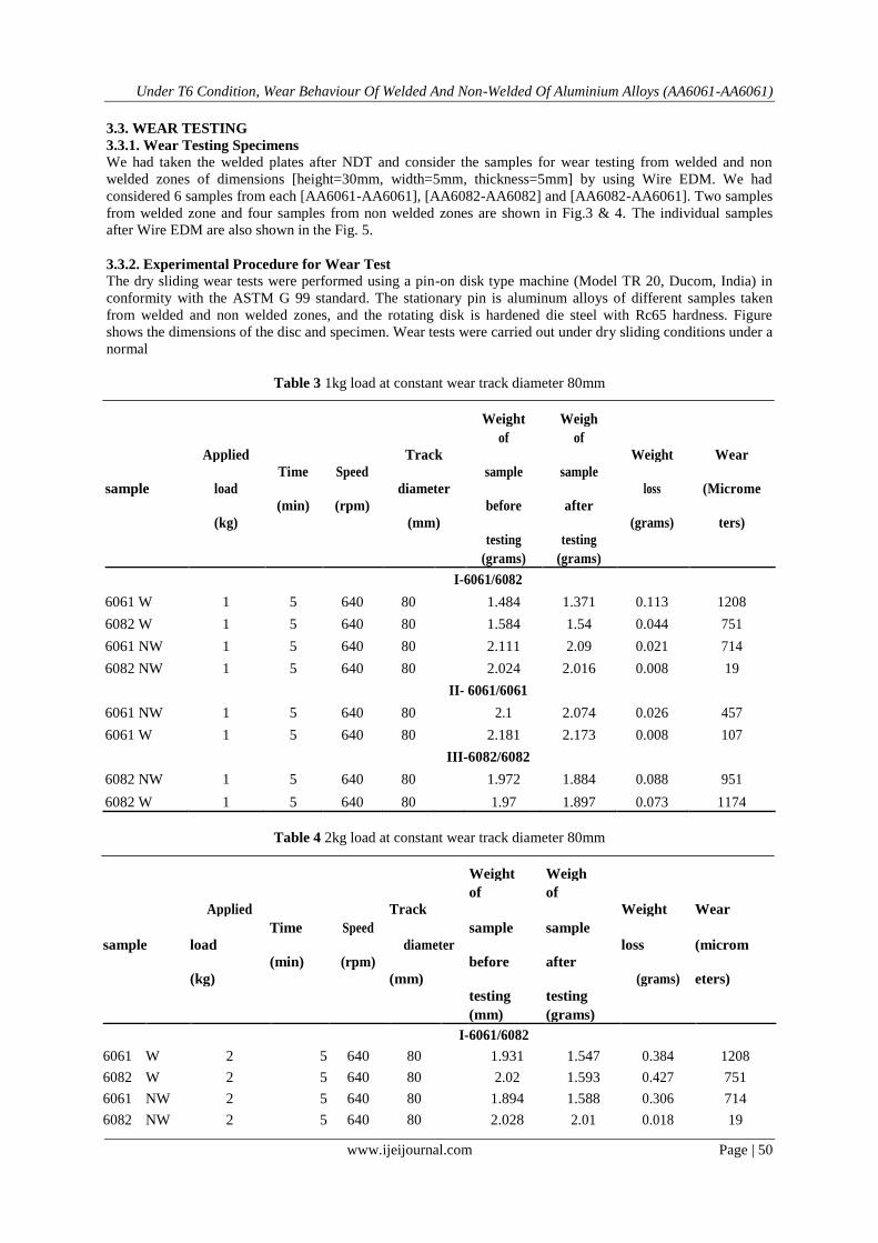
Table 3 1kg load at constant wear track diameter 80mm
Weight Weigh
Applied
Track
of of
Weight Wear
Time Speed sample sample
sample load diameter loss (Microme
(min) (rpm) before after
(kg) (mm) (grams) ters)
testing testing
(grams) (grams)
I-6061/6082
6061 W 1 5 640 80 1.484 1.371 0.113 1208
6082 W 1 5 640 80 1.584 1.54 0.044 751
6061 NW 1 5 640 80 2.111 2.09 0.021 714
6082 NW 1 5 640 80 2.024 2.016 0.008 19
II- 6061/6061
6061 NW 1 5 640 80 2.1 2.074 0.026 457
6061 W 1 5 640 80 2.181 2.173 0.008 107
III-6082/6082
6082 NW 1 5 640 80 1.972 1.884 0.088 951
6082 W 1 5 640 80 1.97 1.897 0.073 1174
Table 4 2kg load at constant wear track diameter 80mm
Weight Weigh
Applied
Track
of of
Weight Wear
Time Speed
sample sample
sample load diameter loss (microm
(min) (rpm) before after
(kg) (mm)
(grams) eters)
testing testing
(mm) (grams)
I-6061/6082
6061 W 2 5 640 80 1.931 1.547 0.384 1208
6082 W 2 5 640 80 2.02 1.593 0.427 751
6061 NW 2 5 640 80 1.894 1.588 0.306 714
6082 NW 2 5 640 80 2.028 2.01 0.018 19

Under T6 Condition, Wear Behaviour Of Welded And Non-Welded Of Aluminium Alloys (AA6061-AA6061)
www.ijeijournal.com Page | 51
II-6061/6061
6061 NW 2 5 640 80 2.094 2.09 0.004 58
6061 W 2 5 640 80 2.066 2.037 0.029 622
III-6082/6082
6082 NW 2 5 640 80 2.045 2.04 0.005 43
6082 W 2 5 640 80 1.965 1.952 0.013 291
Figure 8 Front view of specimens after wear test
Figure 9 Top view of specimens after wear test
Figure 10 Values and graph of wear and frictional force using WINDUCOM Software

Under T6 Condition, Wear Behaviour Of Welded And Non-Welded Of Aluminium Alloys (AA6061-AA6061)
www.ijeijournal.com Page | 52
Figure 10 Values and graph of wear and frictional force using WINDUCOM Software
3.3.4. Metallurgical Examination
The wear tested samples are examined using optical metallurgical microscope and the microstructures are
shown in the Fig.11

Under T6 Condition, Wear Behaviour Of Welded And Non-Welded Of Aluminium Alloys (AA6061-AA6061)
www.ijeijournal.com Page | 53
Figure 11 Microscopic observation of wear tested specimen of (a) I-AA6082NW (b) AA6082W (c) I-
AA6061NW
(d) I-AA6061W (e) III-AA6082NW (f) III-AA6082W (g) II-AA6061NW (h) II-AA6061W
The microstructure shows grooves and fine scratches on the surfaces shown in Fig.11 (e). I the above Fig.11 (a),
(b) & (h) shows sliding direction, cracks and wear debris on the surface of the specimens.

Under T6 Condition, Wear Behaviour Of Welded And Non-Welded Of Aluminium Alloys (AA6061-AA6061)
www.ijeijournal.com Page | 54
4. RESULTS & DISCUSSIONS
Figure 12 Load Vs Wear graph for welded samples at 1kg
Figure 13 Load Vs Wear graph for Non-welded samples at 1Kg
Figure 14 Load Vs Wear graph for welded samples at 2Kg
Under T6 Condition, Wear Behaviour Of Welded And Non-Welded Of Aluminium Alloys (AA6061-AA6061)
www.ijeijournal.com Page | 55
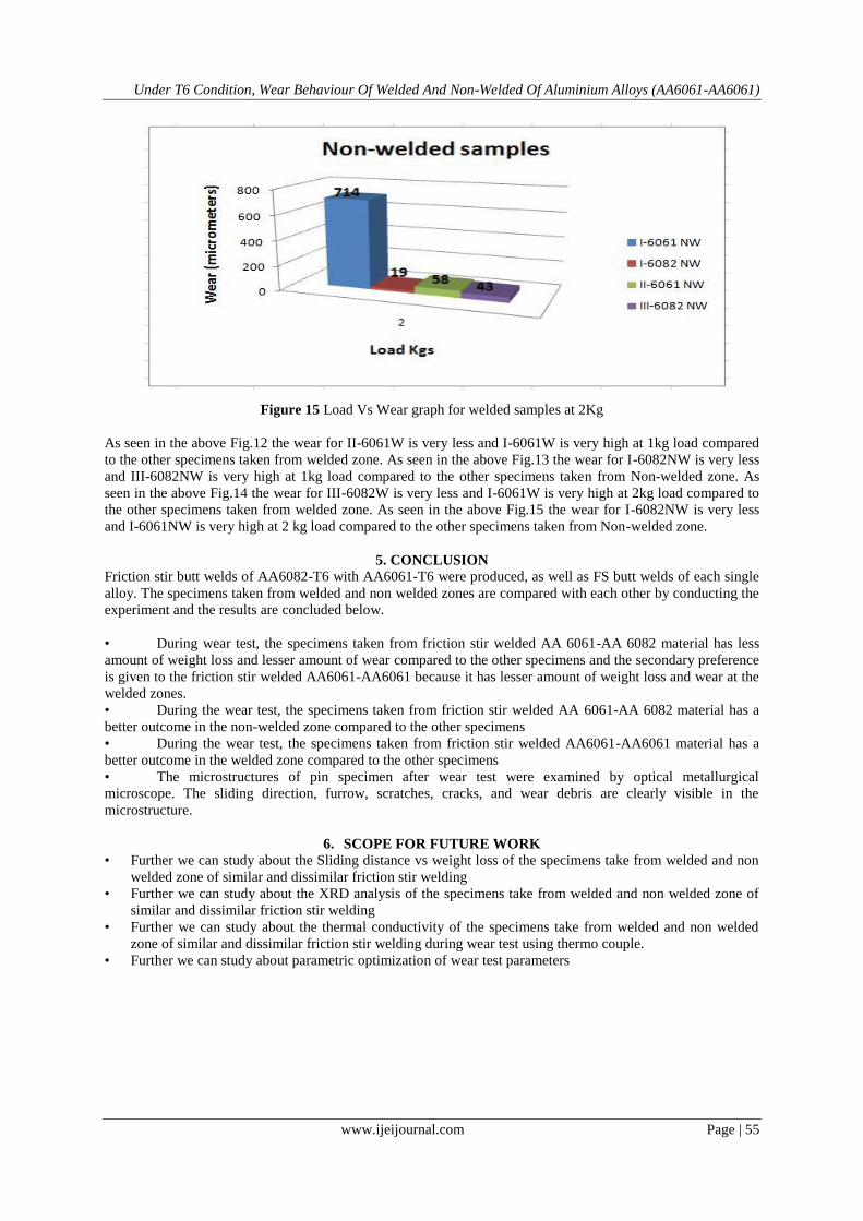
Figure 15 Load Vs Wear graph for welded samples at 2Kg
As seen in the above Fig.12 the wear for II-6061W is very less and I-6061W is very high at 1kg load compared
to the other specimens taken from welded zone. As seen in the above Fig.13 the wear for I-6082NW is very less
and III-6082NW is very high at 1kg load compared to the other specimens taken from Non-welded zone. As
seen in the above Fig.14 the wear for III-6082W is very less and I-6061W is very high at 2kg load compared to
the other specimens taken from welded zone. As seen in the above Fig.15 the wear for I-6082NW is very less
and I-6061NW is very high at 2 kg load compared to the other specimens taken from Non-welded zone.
5. CONCLUSION
Friction stir butt welds of AA6082-T6 with AA6061-T6 were produced, as well as FS butt welds of each single
alloy. The specimens taken from welded and non welded zones are compared with each other by conducting the
experiment and the results are concluded below.
• During wear test, the specimens taken from friction stir welded AA 6061-AA 6082 material has less
amount of weight loss and lesser amount of wear compared to the other specimens and the secondary preference
is given to the friction stir welded AA6061-AA6061 because it has lesser amount of weight loss and wear at the
welded zones.
• During the wear test, the specimens taken from friction stir welded AA 6061-AA 6082 material has a
better outcome in the non-welded zone compared to the other specimens
• During the wear test, the specimens taken from friction stir welded AA6061-AA6061 material has a
better outcome in the welded zone compared to the other specimens
• The microstructures of pin specimen after wear test were examined by optical metallurgical
microscope. The sliding direction, furrow, scratches, cracks, and wear debris are clearly visible in the
microstructure.
6. SCOPE FOR FUTURE WORK
• Further we can study about the Sliding distance vs weight loss of the specimens take from welded and non
welded zone of similar and dissimilar friction stir welding
• Further we can study about the XRD analysis of the specimens take from welded and non welded zone of
similar and dissimilar friction stir welding
• Further we can study about the thermal conductivity of the specimens take from welded and non welded
zone of similar and dissimilar friction stir welding during wear test using thermo couple.
• Further we can study about parametric optimization of wear test parameters
Under T6 Condition, Wear Behaviour Of Welded And Non-Welded Of Aluminium Alloys (AA6061-AA6061)
www.ijeijournal.com Page | 56
ACKNOWLEDGEMENTS
Authors are most grateful and wish to thank Department of Mechanical Engineering, University college
of Engineering & Technology, Acharya Nagarjuna University for giving the permission to conduct the wear
testing and metallurgical testing at Advance material Testing laboratory. Special thanks to technician K. Suresh
who helped in conducting the wear test at Advanced material testing laboratory, ANU. Special thanks to kalva
NDT institute, Hyderabad, helped for NDT.
REFERENCES
[1] Friction Stir Welding And Processing VI edited by Edited by Rajiv Mishra, Murray W. Mahoney, Yutaka
Sato, Yuri Hovanski, Ravi Verma Copyright © 2011 by The Minerals, Metals, & Materials Society. All
rights reserved, Published by John Wiley & Sons, Inc., Hoboken, New Jersey, Published simultaneously
in Canada
[2] R. S. Mishra and Z. Y. Ma. 2005. Friction stir welding and Processing. Material science and Engineering.
250: 1-78.
[3] Guidebook For The Fabrication Of Non-Destructive Testing (NDT) Test Specimens IAEA, VIENNA,
2001, IAEA-TECDOC-TCS-13, ISSN 1011–4289 © IAEA, 2001, Printed by the IAEA in Austria, June,
2001.
[4] Material Science And Engineering- Vol. III-Non-Destructive Testing and Evaluation of Metals- G.A.
Georgiou
[5] A.V. Byeli, A.A. Minevich, A.V. Stepanenko, L.G. Gick, O.V.Kholodilov, Wear resistance and structure
of (Ti, Al)N coatings ,J. Phys. D: Appl. Phys. 25 (1992) A292–A296.
[6] M. Murakawa, S. Takeuchi, Mechanical applications of thin and thick diamond films, Surf. Coat. Tech.
49 (1991) 359–365.
[7] Methods of wear testing for advanced surface coatings and bulk Materials by D.M. Kennedy, M.S.J.
Hashmi, Journal of Materials Processing Technology 77 (1998) 246–253, 0924-0136:98:$19.00 © 1998
Elsevier Science S.A.
[8] Metallurgical Microscopy By Helfrid Modin, Sten Modin, Elsevier, 22-Oct-2013 - Technology &
Engineering.
[9] A. Wang and H.J. Rack, Transition wear behavior of Sic-particulate and Sic-whisker reinforced 709lAI
metal matrix composites, Mater.Sci. Eng., Al47 (1991) 21 l-224.
[10] J. Zhang and A.T. Alpas, Wear regimes and transitions in AIZO, articulate-reinforced aluminium alloys,
Mater. Sci. Eng., A161 (1993) 273-284.
[11] Ludema, Bayer, Tribological Modeling for Mechanical Designers, ASTM Special Technical Publication,
vol. 1105, 1994, p.134.
[12] J.E. Kelley, J.J. Stiglich Jr., G.L. Sheldon, Methods of characterization of tribological properties of
coatings, Surf. Mod. Tech.(1988) 169–187.
[13] E.A. Almond, L.A. Lay, M.G. Gee, Comparison of sliding and abrasive wear mechanisms in ceramics
and cemented carbides, Inst. Phys. Conf. Ser. No. 75: Ch. 9, pp. 919–948.
[14] K. Bouslykhane, P. Moine, J.P. Villain, J. Grilhe, Mechanical properties and wear resistance of ion-beam
assisted sputter-deposited NiTi (N) coatings, Surf. Coat. Tech. 49 (1991) 457–461.
[15] R.K. Schmid, Andrew R. Nicoll, Tailoring the wear resistance of hard metal spray coatings through micro
structural modeling, Sulzer Tech. Rev. 1 (1990).
[16] K. Kato, D.F. Diao, M. Tsutsumi, The wear mechanism of ceramic coating film in repeated sliding
friction, Wear. Mat. ASME (1991).
[17] N Ravinder Reddy and G Mohan Reddy, Friction Stir Welding of Aluminium Alloys - A Review,
International Journal of Mechanical Engineering and Technology, 7(2), 2016, pp. 73–80
[18] Syed Khaja Naimuddin,Touseef Md, Dr. Vidhu Kampurath and Dr. Yousuf Ali, Mechanical Properties
of Friction Stir Welding Joints of Similar & Dissimilar Aluminium Alloys Aa6061 & 6082. International
Journal of Mechanical Engineering and Technology, 7(4), 2016, pp.256–266.