UNDER SINK Reverse Osmosis Filtration System - The · PDF fileSAVE THESE INSTRUCTIONS UNDER...
23
SAVE THESE INSTRUCTIONS UNDER SINK Reverse Osmosis Filtration System CAUTION: Before using water softener, read this manual and follow all safety rules and operating instructions. Installation, Use & Care Guide VRO-3 VRO-4 VRO-5 VRO-5WP REV9-30-13
Transcript of UNDER SINK Reverse Osmosis Filtration System - The · PDF fileSAVE THESE INSTRUCTIONS UNDER...

SAVE THESE INSTRUCTIONS
UNDER SINKReverse Osmosis Filtration System
CAUTION: Before using water softener, read this manual and follow all safety rules and operating instructions.
Installation, Use & Care Guide
VRO-3VRO-4VRO-5VRO-5WP
REV9-30-13

Table of Contents: Page
How Reverse Osmosis Works 1Conditions for Operation 1 - 2Tools Required for Installation 2Reverse Osmosis System Layout and Components 3 - 4Specifications 5Tapping Into Cold Water Line 5Installation of Product Water Faucet 6 - 7Installation for Saddle Drain Clamp 8Installing the Membrane Into the Membrane Housing 8Installing the Filter Cartridges and Filter Housing Bowl Onto Unit 9Mounting the RO Unit Under the Sink 10Mounting the Tank Ball Valve Onto Tank 10Connecting the Tubing 11Icemaker Hook-Up (Optional) 12Start-Up Instructions 126 Month Maintenance 12 - 13Annual Maintenance 14RO Membrane Replacement 17Inline Post Carbon Filter Replacement (VRO-4, VRO-5 & VRO-5WP only) 18Check Air Pressure in the Tank 19Procedure for Extended Non-Use (More than 2 months) 19Troubleshooting Guide for RO Systems 19Drinking Water Contaminants and Treatment 20Limited Warranty 21
Your Water TestHardness gpgIron ppmpH number*Nitrates ppmManganese ppmSulphur yes/noTotal Dissolved Solids*Over 10ppm may be harmful for human consumption. Water conditioners do not remove nitrates or coliform bacteria, this requires specialized equipment.
1
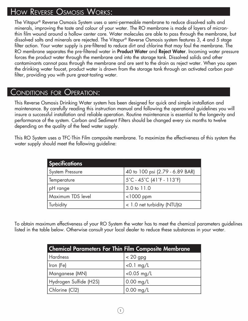
To obtain maximum effectiveness of your RO System the water has to meet the chemical parameters guidelines listed in the table below. Otherwise consult your local dealer to reduce these substances in your water.
The Vitapur® Reverse Osmosis System uses a semi-permeable membrane to reduce dissolved salts and minerals, improving the taste and colour of your water. The RO membrane is made of layers of micron-thin film wound around a hollow center core. Water molecules are able to pass through the membrane, but dissolved salts and minerals are rejected. The Vitapur® Reverse Osmosis system features 3, 4 and 5 stage filter action. Your water supply is pre-filtered to reduce dirt and chlorine that may foul the membrane. The RO membrane separates the pre-filtered water in Product Water and Reject Water. Incoming water pressure forces the product water through the membrane and into the storage tank. Dissolved solids and other contaminants cannot pass through the membrane and are sent to the drain as reject water. When you open the drinking water faucet, product water is drawn from the storage tank through an activated carbon post-filter, providing you with pure great-tasting water.
How ReveRse osmosis woRks:
This Reverse Osmosis Drinking Water system has been designed for quick and simple installation and maintenance. By carefully reading this instruction manual and following the operational guidelines you will insure a successful installation and reliable operation. Routine maintenance is essential to the longevity and performance of the system. Carbon and Sediment Filters should be changed every six months to twelve depending on the quality of the feed water supply.
This RO System uses a TFC-Thin Film composite membrane. To maximize the effectiveness of this system the water supply should meet the following guideline:
Conditions foR opeRation:
SpecificationsSystem Pressure 40 to 100 psi (2.79 - 6.89 BAR)
Temperature 5˚C - 45˚C (41˚F - 113˚F)
pH range 3.0 to 11.0
Maximum TDS level <1000 ppm
Turbidity < 1.0 net turbidity (NTU)Ω
Chemical Parameters For Thin Film Composite MembraneHardness < 20 gpg
Iron (Fe) <0.1 mg/L
Manganese (MN) <0.05 mg/L
Hydrogen Sulfide (H2S) 0.00 mg/L
Chlorine (Cl2) 0.00 mg/L

2
• Do not use this system where the water is microbiologically unsafe or of unknown quality. RO system is for use on potable water only. Source water exceeding chemical parameters requires treatment.
• This Reverse Osmosis element contains a preservative solution to prevent microbiological growth and freezing which, if ingested may cause irritation of the gastrointestinal tract, colic, diarrhea, or other similar symptoms. Therefore on initial installation discard 3 full tanks of product water before drinking or using the water for cooking.
• Drill Bits 1/8”, 3/16”, 1/4”, 3/8” 1/2”, 11/4” Saw Bit• Electric Variable Drill (Cordless Preferred)• Slotted and Phillips Screw Driver• 2 Adjustable Wrenches• Needle Nose Pliers• Teflon Pipe Tape• Safety Glasses• Utility Knife• Level
pReCautions:
tools RequiRed foR installation:

3
1st Stage: Carbon Block Filter 5 micron, 10”2nd Stage: TFC Membrane 50 GPD3rd Stage: Carbon Block Filter 5 micron, 10”
Auto shut off valveOperating Pressure: 40 – 100 psi (2.79 - 6.89 BAR)Operating Temperature: 5 to 45 Celsius
ReveRse osmosis system and Components: VRO-3 Filtration Process
Replacement Parts
Part Number Description Service LifeVS10RF-CTO Carbon Block Filter 5 micron, 10” 6 – 12 months
VROM-50 TFC Membrane 50 GPD @ 60 psi 12 – 18 months
VS10RF-CTO Carbon Block Filter 5 micron, 10” 6 – 12 months
WaDrain terSupply
Valve
3rd Stage 1st StagePressure Tank3.2 U.S. Gallon
Faucet Drain Line 2nd Stage
¼” White
3/8”
3/8”
Blue
¼” Black
3/8” Yellow
Flow Restrictor 300ml
to Air Gap
Blackto Drain

4
1st Stage: Sediment Filter 5 micron, 10”2nd Stage: Carbon Block Filter 5 micron, 10”3rd Stage: TFC Membrane 50 GPD4th Stage: Inline Carbon Filter
Auto shut off valveOperating Pressure: 40 – 100 psi (2.79 - 6.89 BAR)Operating Temperature: 5 to 45 Celsius
ReveRse osmosis system and Components: VRO-4 Filtration Process
Replacement Parts
Part Number Description Service LifeVS10RF-PP Sediment Filter 5 micron, 10” 6 – 12 months
VS10RF-CTO Carbon Block Filter 5 micron, 10” 6 – 12 months
VROM-50 TFC Membrane 50 GPD @60 psi 12 – 18 months
VSRF-IL Inline Carbon Filter 6 – 12 months
Drain WaterSupply
Valve
2nd Stage 1st StagePressure Tank3.2 U.S. Gallon
Faucet 3rd Stage
¼” White
4th Stage
Flow Restrictor 300ml
3/8” Yellow
3/8” Blue
Drain Line¼” Black
to Air Gap
3/8” Blackto Drain

5
1st Stage: Sediment Filter 5 micron, 10”2nd Stage: Carbon Block Filter 5 micron, 10”3rd Stage: Carbon Block Filter 5 micron, 10”4th Stage: TFC Membrane 50 GPD @ 60 psi5th Stage: Inline Carbon Filter
Auto shut off valveOperating Pressure: 40 – 100 psi (2.79 - 6.89 BAR)Operating Temperature: 5 to 45 Celsius
ReveRse osmosis system and Components: VRO-5 Filtration Process
Replacement Parts
Part Number Description Service LifeVS10RF-PP Sediment Filter 5 micron, 10” 6 – 12 months
VS10RF-CTO Carbon Block Filter 5 micron, 10” 6 – 12 months
VS10RF-CTO Carbon Block Filter 5 micron, 10” 6 – 12 months
VROM-50 TFC Membrane 50 GPD @ 60 psi 12 – 18 months
VSRF-IL Inline Carbon Filter 6 – 12 months
WaterSupply
3rd Stage 1st Stage2nd StagePressure Tank3.2 U.S. Gallon
Faucet
Valve
4th Stage
¼” White
3⁄8” Blue
Yellow
Flow Restrictor 300ml
5th Stage
Drain
Drain Line¼” Black
to Air Gap
3/8” Blackto Drain
3⁄8”
6
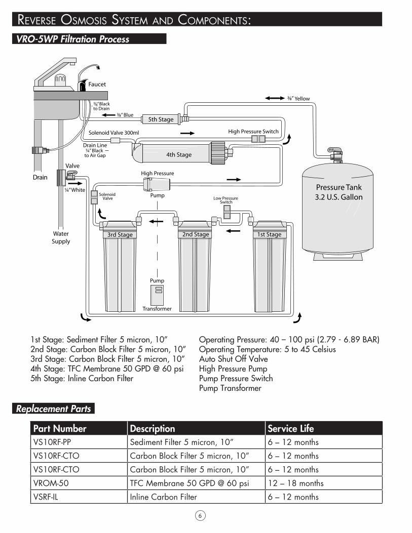
1st Stage: Sediment Filter 5 micron, 10”2nd Stage: Carbon Block Filter 5 micron, 10”3rd Stage: Carbon Block Filter 5 micron, 10”4th Stage: TFC Membrane 50 GPD @ 60 psi5th Stage: Inline Carbon Filter
Operating Pressure: 40 – 100 psi (2.79 - 6.89 BAR)Operating Temperature: 5 to 45 CelsiusAuto Shut Off ValveHigh Pressure PumpPump Pressure SwitchPump Transformer
ReveRse osmosis system and Components: VRO-5WP Filtration Process
Replacement Parts
Part Number Description Service LifeVS10RF-PP Sediment Filter 5 micron, 10” 6 – 12 months
VS10RF-CTO Carbon Block Filter 5 micron, 10” 6 – 12 months
VS10RF-CTO Carbon Block Filter 5 micron, 10” 6 – 12 months
VROM-50 TFC Membrane 50 GPD @ 60 psi 12 – 18 months
VSRF-IL Inline Carbon Filter 6 – 12 months
WaterSupply
Valve
Faucet
4th Stage
5th Stage
3rd Stage 1st Stage2nd Stage
Pressure Tank3.2 U.S. Gallon
¼” White
3⁄8”
Drain
Blue
Yellow
Pump
Transformer
High Pressure
Pump
Solenoid Valve 300ml High Pressure Switch
Low Pressure Switch
Solenoid Valve
3⁄8”3/8” Blackto Drain
Drain Line¼” Black
to Air Gap
7
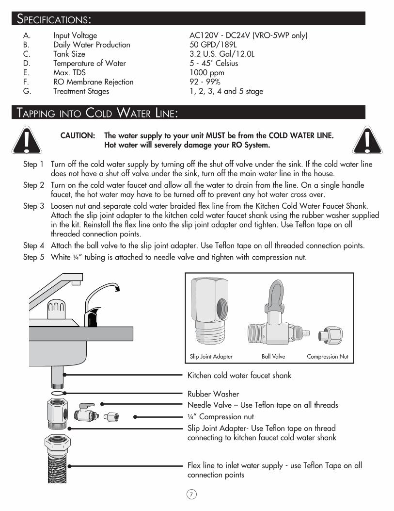
A. Input Voltage AC120V - DC24V (VRO-5WP only)B. Daily Water Production 50 GPD/189LC. Tank Size 3.2 U.S. Gal/12.0LD. Temperature of Water 5 - 45˚ CelsiusE. Max. TDS 1000 ppmF. RO Membrane Rejection 92 - 99%G. Treatment Stages 1, 2, 3, 4 and 5 stage
Step 1 Turn off the cold water supply by turning off the shut off valve under the sink. If the cold water line does not have a shut off valve under the sink, turn off the main water line in the house.Step 2 Turn on the cold water faucet and allow all the water to drain from the line. On a single handle faucet, the hot water may have to be turned off to prevent any hot water cross over.Step 3 Loosen nut and separate cold water braided flex line from the Kitchen Cold Water Faucet Shank. Attach the slip joint adapter to the kitchen cold water faucet shank using the rubber washer supplied in the kit. Reinstall the flex line onto the slip joint adapter and tighten. Use Teflon tape on all threaded connection points.Step 4 Attach the ball valve to the slip joint adapter. Use Teflon tape on all threaded connection points.Step 5 White 1/4” tubing is attached to needle valve and tighten with compression nut.
CAUTION: The water supply to your unit MUST be from the COLD WATER LINE. Hot water will severely damage your RO System.
speCifiCations:
tapping into Cold wateR line:
Kitchen cold water faucet shank
Rubber WasherNeedle Valve – Use Teflon tape on all threads1/4” Compression nutSlip Joint Adapter- Use Teflon tape on thread connecting to kitchen faucet cold water shank
Flex line to inlet water supply - use Teflon Tape on all connection points

8
The drinking water faucet should be positioned with function, convenience and appearance in mind. An adequate flat area is required to allow faucet to rest securely. Check the underside of the location for interference. Most sinks have a pre-drilled 11/2” or 13/8” diameter holes designed for spray hoses. The drinking water faucet may be installed using one of these holes, despite their larger size. If the pre-drilled holes cannot be used, or are in an inconvenient location, it will be necessary to drill a 11/4” hole in the sink or through the countertop next to the sink or the faucet.
CAUTION: Do not drill through a counter top that is more than 1” thickCAUTION: Do not attempt to drill through a tiled, marble, granite or similar countertop. Consult a plumber or the countertop manufacturer for advice or assistanceCAUTION: When drilling through a countertop make sure the area below the drilled area is free of wiring and piping. Make certain that you have ample room to make the proper connection to the bottom of the faucet.CAUTION: Do not attempt to drill through an all-porcelain or porcelain-coated sink. For applications on these types of sinks we recommend using the sprayer hole or mounting the faucet through the countertop. Otherwise consult a plumber or manufacturer for advice or assistance.
installation of pRoduCt wateR fauCet: Drilling the Faucet Hole
Drilling the Faucet Hole in Stainless Steel Sink
Air Gap Faucet Installation
Step 1 Line the bottom of the sink with newspaper to prevent shavings, parts, or tools from falling down the drain.Step 2 Place masking tape over the area to be drilled to help prevent scratches if drill bit slips.Step 3 Mark point with a center punch. Use a 1/4” drill bit to drill a pilot holeStep 4 Use a 1 1/4” hole saw to enlarge the hole. Smooth rough edges with a file.
Step 1 Connect the 1/4” black drain tube from the RO module up to the 1/4” fitting on the air gap faucet. Refer to the picture to the right.Step 2 Then connect the 3/8” black tubing to the air gap RO faucet. Refer to the picture on the right.
1¼”
¼”
¼” Black Drain Line to Air Gap
Black Drain Line from Air Gap
Air Gap WindowNote: The 3/8” black drain tube goes by gravity feed to the saddle drain clamp
connection. Make sure there are no kinks, loops, or sharp bends in the 3/8” black tubing. Failure to make a straight line to the drain may result in reject water leaking through the air gap in the faucet onto the countertop or below the faucet. CAUTION: The installation of this system must be in accordance with all Provincial/State and/or local laws and regulations regarding plumbing and electrical. Please consult regulations concerning the air gap connection on RO faucets in your province or state.

9
installation of pRoduCt wateR fauCet:
A 3/8” to 1/4” quick connect fitting is supplied if you want to by pass the air gap connection on the faucet. In this case the 1/4” black drain tubing connects to one end of the quick connect and the 3/8” black tubing connects to the other end of the quick connect. The 3/8” line then goes to the saddle drain clamp connection. Some provinces/states have a requirement for connection of drain line to air gap faucet.
CAUTION: The installation of this system must be in accordance with all provincial/state and/or local laws and regulations regarding plumbing and electrical. Please consult regulations concerning the air gap connection on RO faucets in your province or state.
To Bypass the Air Gap Faucet
RO Product Water Connection
Step 3 Loosen stem-nut on the faucet.Step 4 Slide Chrome plate and black rubber washer onto the faucet stem. The chrome plate, large rubber faucet washer and faucet body are above sink or countertop.Step 5 Feed the 3/8” and 1/4” black tubing through the pre-drilled hole in the sink/counter.Step 6 Place the faucet through the drilled faucet hole and add spacer, securing plate, star lock washer and stem nut.Step 7 Tighten stem nut firmly while aligning faucet in the desired location.Step 8 Attach quick connect to stem of air gap faucet. Step 9 The 3/8 blue tubing is attached to the quick connect (product water) from RO unit.
3/8” Side of Connector 1/4” Side of Connector
Counter top
Chrome PlateRubber Washer
Counter top
Securing Plate
Spacer
L
Quick connect for RO to faucet
ock Washer¼” Nut
3/8” Blue LineProduct Water

10
Step 1 Attach the drain clamp to the vertical section of the drain pipe, about 6 inches above the trap. Make sure the opening on the drain clamp is facing towards the drinking water faucet.Step 2 Using the fittings hole of the drain clamp as a guide, drill a ¼” hole through one side of the drainpipe.Step 3 Remove the drain clamp from the drainpipe and enlarge the hole with a ½” drill bit. Use a file to remove rough edges from the drilled hole.Step 4 Make sure the black rubber gasket is adhered to the inside of the drain clamp and place the drain clamp assembly over the drilled hole. Look through the hole and position the clamp so that the center of the clamp hole is slightly higher (1/16”) than the center of the drilled hole. Tighten the clamp securely.Step 5 Connect 3/8” black tube to saddle clamp quick connect.
Step 1 Cleans hands before removing the plastic packaging from the RO membraneStep 2 Remove the tube connection from the RO membrane cap.Step 3 Loosen the cap by using the wrench provided in a counterclockwise direction.Step 4 Lubricate the O-rings on the new membrane with water. Insert the end with the two black O-rings first into the housing.Step 5 Once the membrane has been inserted into the housing give a firm push to properly seat the membrane.Step 6 Check to see that the O-ring is in the cap properly seated. Replace membrane housing cap and tighten with the supplied wrench in the clockwise direction.
installation of saddle dRain Clamp:
installing tHe membRane into tHe membRane Housing:
Drain Tubing
Drain ClampFront Plat
Quick connect
e
1/4” Bolt
Drain Pipe
1/4” Nut
Drain ClampBack Plate
Mount Drain Valve HereNever
MountHere
3/8” Black Line
2 Rubber O-Rings
This end inserted into housing �rst
Wrench
Tighten Housing Cap by Turning Wrench Clockwise
Membrane Housing 2 Rubber O-Rings

11
Step 1 Insert a Carbon Block Filter into the 1st filter housing bowl which is the one on the water inlet side (white tubing) of the RO system and install housing bowl onto the housing head by screwing in the clock wise direction. Tighten using the wrench supplied.Step 2 Insert the Carbon Block filters into second housing bowl and screw the housing bowl onto the housing head by rotating in the clock wise direction. Tighten using the wrench supplied.
Step 1 Insert a Sediment Filter (cloth like appearance) into the 1st filter housing bowl which is the one on the water inlet side (white tubing) of the RO system and install housing bowl onto the housing head by screwing in the clock wise direction. Tighten using the wrench supplied.Step 2 Insert the Carbon Block filters into second housing bowl and screw the housing bowl onto the housing head by rotating in the clock wise direction. Tighten using the wrench supplied.
installing tHe filteR CaRtRidges and filteR Housing bowl onto unit:
Model VRO-3
Model VRO-4
Rubber O-Rings
WrenchWrench
Filter Housing
Water Inlet
Carbon Block Filters
Filter Housing Bowls
RO Water To Faucet
RO Water toStorage Tank
Rubber O-Rings
WrenchWrench
Water Inlet
Carbon Block Filter Sediment Filter
Filter Housing Bowls
Water to Membrane
Filter Housing
O-Rings O-Rings
Filter Housing
Wrench Wrench
Water Inlet
RO Water To Faucet
RO Water toStorage Tank
Filter Housing Bowls
Sediment FilterCarbon Block Filters
RO Membrane
Inline Carbon Filter
RO Membrane
Inline Carbon Filter
RO Membrane
Step 1 Insert a new sediment filter (Cloth like appearance) into the 1st filter housing bowl which is the one on the water inlet side (white tubing) of the RO system and install housing bowl onto the housing head by screwing it on in the clockwise direction. Tighten using the wrench supplied.Step 2 Make sure that the plastic ring seal is on both ends of the filter. Insert the Carbon Block Filter into the 2nd filter housing bowl. Screw the housing bowl onto the housing head in a clockwise direction.Step 3 Make sure that the plastic ring seal is on the top side of the cartridge. Insert the Carbon Block Filter into 3rd Filter. Screw the housing bowl onto the housing head in a clockwise direction.
Model VRO-5 and Model VRO-5WP

12
Step 1 Locate the RO unit on the back or right wall under the sink. Make sure to allow ample space for the installation and plumbing connections. To change the filter cartridges, a minimum of 4 ” of clearance is required underneath the filter housings. A minimum of 4 inches of clearance from the left bracket mounting screw hole.Step 2 Install mounting screws at least 17 1/8” inches from cabinet floor. Leave 5/16 inch space between the head of the screw and the wall to slip bracket onto the screws.
The spacing between the mounting holes is as follows: VRO-3 : 7 1/8” VRO-5 : 11 1/4” VRO-4 : 6” VRO-5WP : 12 1/8”
Step 1. Connect the ball valve to the water storage tank thread on the upper side of the tank. Make sure it is tight but not over tight.Step 2. Connect the yellow 3/8” tubing to the tank ball valve. Push the tubing in all the way to make sure it is properly seated. This is a quick connect.Step 3. Turn the tank ball valve off.
mounting tHe Ro unit undeR tHe sink:
mounting tHe tank ball valve onto tank:
13 1/2”
4” Minimum Clearance
4”
Model: VRO-4
13 1/2”
4” Minimum Clearance
4”
Models VRO-5 and VRO-5WP
13 1/2”
4” Minimum Clearance
4”
Model: VRO-3
CAUTION: Do not tamper with the air valve on the storage tank. It has been preset and screwed on with black cap by the manufacturer.
Ball ValveOFF
Ball ValveON

13
Pressure Tank3.2 U.S. Gallons
Yellow Line
Blue Line
¼” Black Drain Lineto Drain Black
Line to drain
Air Gap FaucetCounter top
Flow Restrictor 300ml
¼” White Line
All tubing is colour coded for ease of installation.All connection points are colour coded with a tab block: white, yellow, blue and black.
¼” Black – Connects the waste water from the RO membrane to the Air Gap faucet intake line¼” White – Connects the tap water to the sediment pre-filter3/8” Yellow – Connects the RO membrane to the holding tank3/8” Blue – Connects the carbon post filter to the faucet3/8” Black – Connects from Air Gap Faucet to saddle drain
Each connection point has coloured plugs to match the colour of the tubing that connects at that point. The plugs must be removed before installing the tubing. Push in the collar and pull the plug out.Quick connect fittings are used throughout the system. To insure an optimal seal, tubing should be cut with the end square. An angled cut or distortion of the tubing will not provide a proper seal and may cause leaks.To install a tube, push in the collet until unit seats firmly. To remove a tube, push in the collet and pull out the tube.
Reference the diagram below for colour and connection point in the RO System.
ConneCting tHe tubing:
CAUTION: Before cutting the supplied tubing measure the distance between the components.
Insert Tubing Into Collet
Push in blue horseshoe to secure tubing
To remove, pull up horseshoe, push in collet and pull tubing

14
Install 1/4” polypropylene plastic tubing if your refrigerator is within 25 ft. of your RO unit. Do not use copper tubing since an objectionable taste can result in the ice cubes. If the refrigerator is over 25 ft from the RO Unit it is recommended to use 3/8” tubing. Install a tee in the blue tubing between the final post filter and the faucet. It is recommended to install a ball valve in the line to your ice maker to allow pressure to increase sufficiently in the storage tank for the ice maker solenoid to operate properly. Leave the ball valve in the closed position until the tank is full after the start up procedure is completed.
Step 1 Turn on the incoming cold water ball valve and the main under sink valve but close the storage tank ball valve.Step 2 Check System for leaks, tighten if necessary.NOTE: If you have connected your RO system to a refrigerator/ice maker, make sure the ice maker is off (do not allow water to flow to the ice maker until flush is complete and the tank has been allowed to fill completely. Connection from the RO to the icemaker system should have an in-line valve installed before the icemaker so it can easily be closed to prevent water flowing to the ice maker during start up and periodic maintenance. Your RO tank must be allowed to fill up fully for the ice maker system to work properly.Step 3 Open the RO Faucet and leave it open until water begins to trickle out (it will come out slowly). It will take 2 minutes for the water to start to drip. Let the water drip for 10 minutes.Step 4 Close the RO faucet allowing the storage tank to fill with water. It may take 3.5 hours to fill the tank completely depending on the production capability of the membrane, local water temperature and water pressure.
Step 5 After the tank is full (you will hear the water stop), open the RO Faucet to flush the tank completely. You will know that the tank is empty when the flow rate from the RO faucet is down to a trickle. Repeat steps 4 and 5 until you have discarded 3 tanks of water.Step 6 Close the RO faucet and allow the holding tank to refill. The process will take 3 to 3.5 hours to complete.Step 7 When the tank is full you can enjoy the RO water for drinking and cooking.Step 8 Check for leaks daily for the first week and periodically thereafter.Step 9 During the first week you may notice a milky colour. These are simply air bubbles in the water. The water is safe to drink.
This model has a booster pump to increase the pressure in the line. The increase line pressure produces more gallons per day since the membrane is operating more efficiently. To put an electrical outlet in the cabinet below the kitchen sink consult an electrician.
iCemakeR Hook-up (optional):
staRt-up instRuCtions:
eleCtRiCal outlet foR model #: vRo-5wp:
CAUTION: The installation of the power outlet in the cabinet below the sink must comply with all provincial / state / and / or local laws and regulations regarding electrical services.
CAUTION: Do not drink the water from the first 3 tanks produced by your newly purchased system.

15
Depending on which model was purchased the chart below will assist with placement of filter cartridges.
Note: Use the Filter wrench supplied with RO systemStep 1 Turn off the incoming water supply to the RO by turning the ball valve clock wise until it stops.Step 2 Close the holding tank valve.Step 3 Open the RO faucet and allow water to drain to release system pressure.Note: Water may be saved in a container for drinking or to rinse system parts.Step 4 For more leverage you may leave the RO unit attached to the wall of the cabinet. If you are unable to access the unit while it is mounted, remove it prior to changing filters. Starting with the closet housing stage 1, remove it by turning it clockwise (left), empty water, then discard filter. Continue on the 2nd housing (Stage 2) and 3rd housing (Stage 3).Note: The 3 stage RO system has to two vertical housings, 4 & 5 stage RO system have three vertical housings.Step 5 Clean the filter housings bowls with a mild soap solution and rinse with water. Check the O-ring and lubricate with water only. Do not use petroleum based lubricants such as Vaseline.Note: Before re-installing the filter bowls back on the system, check O-rings to make sure they still are in place.For Model VRO-3:Step 1 Insert a 5 micron Carbon Block filter (white end cap and plastic netting) into the 1st filter housing which is the one on the water inlet side (white tubing) of the RO system and re-install housings.Step 2 Insert a 5 micron Carbon Block filter (white end cap and plastic netting) into 2nd filter bowl and re-install housings.Skip to Step 6.For Model VRO-4:Step 1 Insert a 5 micron Sediment filter (cloth like appearance) into the 1st filter housing which is the one on the water inlet side (white tubing) of the RO system and re-install housings.Step 2 Insert a 5 micron Carbon Block filter (white end cap and plastic netting) into 2nd filter bowl and re-install housings.Skip to Step 6.For Model VRO-5 and VRO-5WP:Step 1 Insert a 5 micron Sediment filter (cloth like appearance) into the 1st filter housing which is the one on the water inlet side (white tubing) of the RO system and re-install housings.Step 2 Insert a 5 micron Carbon Block filter into 2nd filter bowl and re-install housings.
6 montH system maintenanCe:
Model # Stage 1 Stage 2 Stage 3 Stage 4 Stage 5
VRO-35 micron Carbon Block
Filter Part #VS10RF-CTO
RO MembranePart # VROM-50
5 micron Carbon BlockFilter Part #
VS10RF-CTO
VRO-45 micron Sediment
Filter Part # VS10RF-PP
5 micron Carbon BlockFilter Part #
VS10RF-CTO
RO MembranePart # VROM-50
Inline Carbon FilterPart # VSRF-IL
VRO-55 micron Sediment
Filter Part # VS10RF-PP
5 micron Carbon BlockFilter Part #
VS10RF-CTO
5 micron Carbon BlockFilter Part #
VS10RF-CTO
RO MembranePart # VROM-50
Inline Carbon FilterPart # VSRF-IL
VRO-5WP5 micron Sediment
Filter Part # VS10RF-PP
5 micron Carbon BlockFilter Part #
VS10RF-CTO
5 micron Carbon BlockFilter Part #
VS10RF-CTO
RO MembranePart # VROM-50
Inline Carbon FilterPart # VSRF-IL

16
Step 3 Insert a 5 micron Carbon Block filter (white end cap and plastic netting) into 3rd filter bowl and re-install housings.Continue to Step 6.Step 6 Turn water supply on by turning the needle valve on the slip joint counter clockwise.Step 7 Open the RO faucet and leave open until water begins to trickle out (it will come out very slowly). Allow to drip for 5 minutesStep 8 Close the RO faucet.Step 9 Open valve on the storage tank.
Note: Sanitizing of unit is recommendedStep 1 Perform steps 1 through 5 in the Six Month System Maintenance.Note: If not sanitizing the system skip to step 8.Step 2 Remove the RO membrane from the housing and rest in a clean sanitary place. (Refer to Membrane Replacement section for directions on removing the membrane). Replace cap onto empty membrane housing and re-connect tubing.Step 3 Leaving the filters out from stages 1,2,3, replace stage 2 and 3 empty filter housings (hand tight) onto unit. Measure and pour either ½ cup of hydrogen peroxide or 2 table spoons of common household bleach into the 1st filter (Stage 1) and hand tighten onto unit.Step 4 With the RO Faucet in the closed position turn on the incoming water supply to the system by turning the needle valve on the slip joint adapter counter clockwise. Wait 1 minute for the unit to pressurize. Turn on the RO Faucet and let the water run for 30 seconds. Turn off the RO faucet and let the unit rest for 2 minutes. Finally, open the RO faucet and let the water run for 5 more minutes.Step 5 Turn off the incoming water supply to the system by turning the needle valve on the slip joint clockwise until it stops. Keep the RO faucet open until the storage tank is completely drained.Step 6 Open the membrane housing and re-install the RO membrane while making sure not to kink the O-rings. (Refer to Membrane Replacement Section)For Model VRO-3:Step 1 Remove filter housings at stages 1 and 3 and empty the water.Step 2 Insert a 5 micron Carbon Block filter (white end cap and plastic netting) into the 1st filter housing which is the one on the water inlet side (white tubing) of the RO system and re-install housing.Step 3 Insert a new 5 micron Carbon Block filter (white end cap and plastic netting) into 2nd filter bowl and re-install housing.Skip to Step 7.For Model VRO-4:Step 1 Remove filter housings at stages 1 and 2 and empty the water.Step 2 Insert a 5 micron Sediment filter (cloth like appearance) into the 1st filter bowl which is the one on the water inlet side (white tubing) of the RO system and re-install housing.Step 3 Insert a 5 micron Carbon Block filter (white end cap and plastic netting) into 2nd filter bowl and re-install housings.Step 4 The carbon in-line filter is located between the RO faucet and storage tank. It is attached to the RO Membrane with brackets. The blue tubing is attached to the Carbon Post-filter. Remove it by loosening the fitting on both ends of the post filter and replace with new filter.Skip to Step 7.
annual maintenanCe:

17
For Model VRO-5 and VRO-5WP:Step 1 Remove filter housings at stages 1, 2, and 3 and empty the water.Step 2 Insert a 5 micron Sediment filter (cloth like appearance) into the 1st filter housing which is the one on the water inlet side (white tubing) of the RO system and re-install housings.Step 3 Insert a new 5 micron Carbon Block filter into 2nd filter bowl and re-install housings.Step 4 Insert a new 5 micron Carbon Block filter (white end cap and plastic netting) into 3rd filter bowl and re-install housings.Step 5 The carbon in-line filter is located between the RO faucet and storage tank. It is attached to the RO Membrane with brackets. The blue tubing is attached to the Carbon Post-filter. Remove it by loosening the fitting on both ends of the post filter and replace with new filter.Continue to Step 7.Note: This is a good time to check the air pressure in your storage tank. For instructions please refer to page 18.Step 7 Perform steps 6 through 9 in the Six Month System Maintenance section for startup directions.
The membrane has a life expectancy between 12 to 18 months, depending on the incoming water conditions and the amount the RO system is used. The reverse osmosis membrane is critical for effective reduction of total dissolved solids (TDS). The product water should be tested periodically to verify that the system is performing satisfactorily.Step 1 Turn off the incoming water supply to the RO by turning the needle valve on the slip joint connection clockwise until it stops.Step 2 Close the valve on the holding tank.Step 3 Open the RO Faucet and allow water to drain from the tank until it is completely empty.
Step 1 Remove the tube fittings from the RO membrane cap.Step 2 Use the wrench provided to remove the cap from the housing.Step 3 Use a pair of pliers to remove the membrane from the housing. Grip the membrane and pull firmly on the membrane to remove from the housing and discard.
Step 4 Lubricate the O-rings on the new membrane with water only. Insert the end with the two black O-rings first into the housing.Step 5 Once the membrane has been inserted into the housing you must give a firm push to properly seat the membrane. Replace membrane housing cap and tighten with the supplied wrench.Step 6 The drain flow restrictor must be replaced each time you change the membrane and is located by following the black tubing to the RO system. The flow restrictor is below the RO membrane on the attachment bracket. It reads Flow 300. To remove, cut the tie wrap and loosen the tube connections to it. Remove the flow restrictor and replace with a new one. Place a new tie wrap to secure to the bracket.Step 7 Follow the start up instructions on page 14.
Ro membRane ReplaCement:
Removing the Membrane:
Installing the Membrane:
18
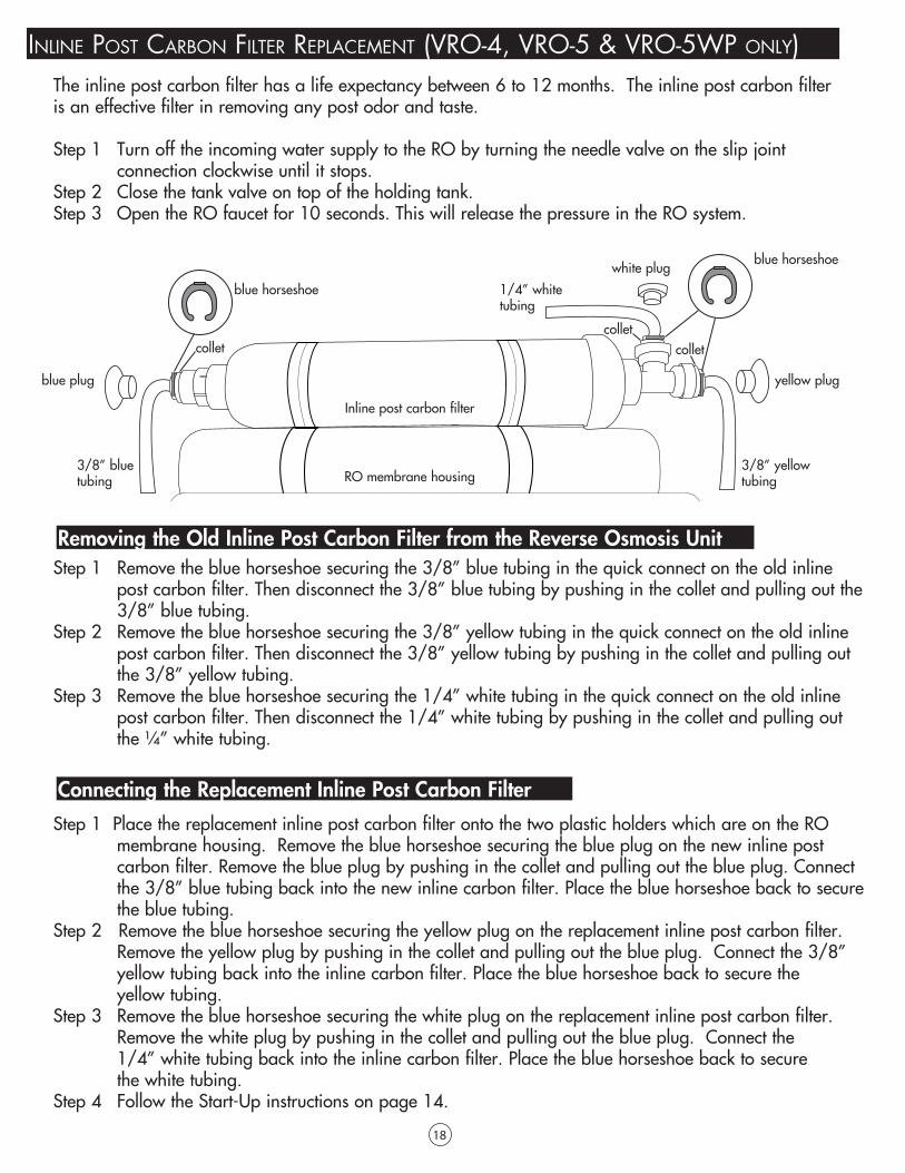
inline post CaRbon filteR ReplaCement (vRo-4, vRo-5 & vRo-5wp only)
Step 1 Remove the blue horseshoe securing the 3/8” blue tubing in the quick connect on the old inline post carbon filter. Then disconnect the 3/8” blue tubing by pushing in the collet and pulling out the 3/8” blue tubing.Step 2 Remove the blue horseshoe securing the 3/8” yellow tubing in the quick connect on the old inline post carbon filter. Then disconnect the 3/8” yellow tubing by pushing in the collet and pulling out the 3/8” yellow tubing.Step 3 Remove the blue horseshoe securing the 1/4” white tubing in the quick connect on the old inline post carbon filter. Then disconnect the 1/4” white tubing by pushing in the collet and pulling out the ¼” white tubing.
Step 1 Place the replacement inline post carbon filter onto the two plastic holders which are on the RO membrane housing. Remove the blue horseshoe securing the blue plug on the new inline post carbon filter. Remove the blue plug by pushing in the collet and pulling out the blue plug. Connect the 3/8” blue tubing back into the new inline carbon filter. Place the blue horseshoe back to secure the blue tubing.Step 2 Remove the blue horseshoe securing the yellow plug on the replacement inline post carbon filter. Remove the yellow plug by pushing in the collet and pulling out the blue plug. Connect the 3/8” yellow tubing back into the inline carbon filter. Place the blue horseshoe back to secure the yellow tubing.Step 3 Remove the blue horseshoe securing the white plug on the replacement inline post carbon filter. Remove the white plug by pushing in the collet and pulling out the blue plug. Connect the 1/4” white tubing back into the inline carbon filter. Place the blue horseshoe back to secure the white tubing.Step 4 Follow the Start-Up instructions on page 14.
The inline post carbon filter has a life expectancy between 6 to 12 months. The inline post carbon filter is an effective filter in removing any post odor and taste.
Step 1 Turn off the incoming water supply to the RO by turning the needle valve on the slip joint connection clockwise until it stops.Step 2 Close the tank valve on top of the holding tank.Step 3 Open the RO faucet for 10 seconds. This will release the pressure in the RO system.
blue horseshoe
collet colletcollet
RO membrane housing
blue horseshoe
yellow plug
white plug
3/8” yellow tubing
3/8” blue tubing
1/4” white tubing
blue plug
Removing the Old Inline Post Carbon Filter from the Reverse Osmosis Unit
Connecting the Replacement Inline Post Carbon Filter
Inline post carbon filter

19
Important: Check air pressure only when the tank is empty of water! Check air pressure in the storage tank when you notice a decrease in available water from the RO system. Air can be added with a bicycle pump using the valve that is located on the bottom of the tank cover by a black cap.Step 1 Turn off the incoming water supply to the RO by turning the needle valve counter clockwise until it stops. Follow the white tubing from the RO system to the intake water valve location.Step 2 Open the RO Faucet and allow the water to drain from the tank until it is completely empty.Tip: When water from the RO faucet slows to a trickle, with the faucet still in the open position, you may add air to the tank to purge any left over water, this will ensure that the tank is completely empty.Step 3 Once all the water in the tank is purged, check the air pressure using an air pressure gauge,it should read between 5 to 7 psi. (Digital air pressure gauge is recommended)Step 4 Follow start-up procedure on page 14.
Turn off water supply by turning the RO intake water valve in a counterclockwise direction until it stops and open the RO faucet to empty the storage tank. Once the storage tank is empty, remove the membrane and place it in a sealed plastic bag and store in the refrigerator.
CHeCk aiR pRessuRe in tHe tank:
pRoCeduRe foR extended non-use (moRe tHan 2 montHs):
tRoublesHooting guide foR tHe Ro systems:
HS)
PROBLEM REASON SOLUTION
Milky coloured water Air in SystemAir in the system is a normal occurrence duringinitial start-up of the RO system. This milky colour will disappear during normal use within 1 to 2 weeks.
Noise from faucet
Air Gap Faucet
Location of drain saddle
Restriction in drain line
Inherent sound with an air gap faucet
Relocate the drain to a horizontal location
Clear blockage that is sometimes caused bydebris from garbage disposal unit or dishwasher
Small amount of water leakageSystem just started up
Air pressure in storage tank is low
Normally it takes 4-6 hours to fill the RO tank. Low water pressure and/or temperatures can reduce the water production rate.
Add air pressure to the storage tank, the pressure should be 5 to 7 psi when the tank is empty.
Slow water production
Low water pressure
Crimps in tubing
Clogged pre-filters
Fouled membrane
This system requires min. 40 psi incoming waterpressure. A booster pump maybe needed in lowwater pressure area.
Check tubing straighten or repair as necessary.
Replace pre-filters.
Replace the membrane.
Offensive water taste or smell
Post carbon filter is depleted
Fouled Membrane
Sanitizer not flushed out
Replace the post carbon filter
Replace the membrane
Drain storage tank and refill it overnight.
No drain water Clogged flow restrictor Replace the flow restrictor
Leaks
Fittings not tightened
Missing O-ring
Misalignment of hole in drain saddle
Tighten fittings as necessary
Contact local dealer
Realign drain saddle

20
The RO membrane conforms to NSF/ANSI Standard 58 for component material safety and may reduce the following substances listed below. The Vitapur® RO systems use a TFC-Thin Film composite membrane.
* % Rejection rates are estimates only and are dependant on many variables, such as source water contaminant concentrations.
dRinking wateR Contaminants and tReatment:
Cations
Substance % REJECTION TFC*Sodium 99
Calcium 99
Magnesium 99
Potassium 98
Iron 99
Manganese 99
Aluminum 99
Ammonium 97
Copper 99
Nickel 99
Zinc 99
Strontium 99
Cadmium 99
Silver 98
Mercury 98
Barium 99
Chromium 99
Lead 99
AnionsChloride 99
Bicarbonate 98
Nitrate 97
Fluoride 98
Silicate 98
Phosphate 99
Chromate 99
Cyanide 95
Sulfate 99
Thiosulfate 99
Ferro cyanide 97
Bromide 98
Borate 50
Arsenic 99
Selenium 99
Biological & Particulate RemovalBacteria >99
Protoxzoa >99
Ameobic Cysts >99
Giardia >99
Asbestos >99
Sediment/Turbidity >99
Retailer: Model Number:
Serial Number: Purchase Date:
limited waRRanty:
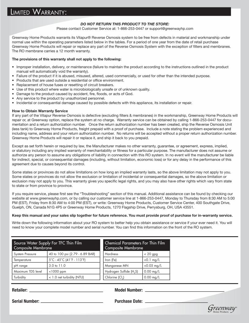
Source Water Supply For TFC Thin Film Composite MembraneSystem Pressure 40 to 100 psi (2.79 - 6.89 BAR)
Temperature 5˚C - 45˚C (41˚F - 113˚F)
pH range 3.0 to 11.0
Maximum TDS level <1000 ppm
Turbidity < 1.0 net turbidity (NTU)
Chemical Parameters For Thin Film Composite MembraneHardness < 20 gpg
Iron (Fe) <0.1 mg/L
Manganese MN <0.05 mg/L
Hydrogen Sulfide (H2S) 0.00 mg/L
Chlorine (Cl2) 0.00 mg/L
DO NOT RETURN THIS PRODUCT TO THE STORE: Please contact Customer Service at: 1-866-253-0447 or [email protected]
Greenway Home Products warrants its Vitapur® Reverse Osmosis system to be free from defects in material and workmanship under normal use within the operating parameters listed below in the tables. For a period of one year from the date of retail purchase Greenway Home Products will repair or replace any part of the Reverse Osmosis System with the exception of filters and membranes. The RO membrane carries a 12 month warranty.
The provisions of this warranty shall not apply to the following:
• Improper installation, delivery, or maintenance (failure to maintain the product according to the instructions outlined in the product manual will automatically void the warranty).• Failure of the product if it is abused, misused, altered, used commercially, or used for other than the intended purpose.• Products that are used outside a residential or office environment.• Replacement of house fuses or resetting of circuit breakers.• Use of this product where water is microbiologically unsafe or of unknown quality.• Damage to the product caused by accident, fire, floods, or acts of God.• Any service to the product by unauthorized personnel.• Incidental or consequential damage caused by possible defects with this appliance, its installation or repair.
How to Obtain Warranty ServiceIf any part of the Vitapur Reverse Osmosis is defective (excluding filters & membranes) in the workmanship, Greenway Home Products will repair or, at Greenway option, replace the system at no charge. Warranty service can be obtained by calling 1-866-253-0447 for docu-mentation and a return authorization number. Once the return authorization number has been created, ship the Reverse Osmosis Unit (less tank) to Greenway Home Products, freight prepaid with a proof of purchase. Include a note stating the problem experienced and including name, address and your return authorization number. No returns will be accepted without a proper return authorization number. Greenway Home Products will repair it or replace it, and ship it back to you prepaid.
Except as set forth herein or required by law, the Manufacturer makes no other warranty, guarantee, or agreement, express, implied, or statutory including any implied warranty of merchantability or fitness for a particular purpose. The manufacturer does not assume or authorize any person to assume any obligations of liability in connection with this RO system. In no event will the manufacturer be liable for indirect, special, or consequential damages (including, without limitation, economic loss) or for any delay in the performance of this agreement due to causes beyond its control.
Some states or provinces do not allow limitations on how long an implied warranty lasts, so the above limitation may not apply to you. Some states or provinces do not allow the exclusion or limitation of incidental or consequential damages, so the above limitation or exclusion may not apply to you. This warranty gives you specific legal rights, and you may also have other rights which vary from state to state or from province to province.
If you require service, please first see the “Troubleshooting” section of this manual. Additional assistance can be found by checking our website at www.greenwayhp.com, or by calling our customer service line at 1-866-253-0447, Monday to Thursday from 8:30 AM to 5:00 PM (EST), Friday from 8:30 AM to 4:00 PM (EST), or write: Greenway Home Products, Customer Service Center, 400 Southgate Drive, Guelph, ON, Canada N1G 4P5 or Greenway Home Products, 1270 Flagship Drive, Perrysburg, OH, USA 43551.
Keep this manual and your sales slip together for future reference. You must provide proof of purchase for in-warranty service.
Write down the following information about your RO system to better help you obtain assistance or service if your ever need it. You will need to know your complete model number and serial number. You can find this information on the front of the RO system.