UNCLASSIFIED - Defense Technical Information Center · UNCLASSIFIED SECURITY ... Test 113 - Analog...
48
UNCLASSIFIED SECURITY CLASSIFICATION OF THIS PAGE (When Data Entered) REPORT DOCUMENTATION PAGE r REPORT NUMBER NOSC Technical Report 396 (TR 396) 2. GOVT ACCESSION NO 4. TITLE (and Subtitle) COMPUTER DISPLAY SET AN/UYQ-21 TECHEVAL TEST System meets all specifications and is judged to be suitable for OPEVAL 7. AUTHORfsJ LtCCCoghillIII,USN JD Baxter DC Lutz READ INSTRUCTIONS BEFORE COMPLETING FORM 3. RECIPIENT'S CATALOG NUMBER 5. TYPE OF REPORT & PERIOD COVERED Final Report for Period 3 May 1978- 12 January 1979 6. PERFORMING ORG. REPORT NUMBER 8. CONTRACT OR GRANT NUMBERfs; 9. PERFORMING ORGANIZATION NAME AND ADDRESS Naval Ocean Systems Center San Diego CA 92152 II. CONTROLLING OFFICE NAME AND ADDRESS Naval Ship Engineering Center (6172) Washington DC 20362 U. MONITORING AGENCY NAME 4 ADDRESSf// dlUerent from Controlllni Ottlce) 10. PROGRAM ELEMENT, PROJECT, TASK AREA 4 WORK UNIT NUMBERS 64518N,S0251-CC, 15580, N0002478WRG004 12. REPORT DATE 9 March 1979 13. NUMBER OF PAGES 48 15. SECURITY CLASS, (of this report) Unclassified 15a. DECLASSIFl CATION/DOWN GRADING SCHEDULE 16. DISTRIBUTION STATEMENT (ot this Report) Approved for public release; distribution unlimited 17. DISTRIBUTION STATEMENT (of the abstract entered In Block 20, It dlUerent from Report) 18. SUPPLEMENTARY NOTES 19. KEY WORDS fConlinue on reverse aide it neceaaary and Identtly by block number) Computers Display systems Computer Display Set AN/UYQ-21 (V) Tests TECHEVAL testing 20. ABSTRACT fCondnue on reverse aide II neceaaary and identity by block number) This report documents the technical evaluation (TECHEVAL) testing of Computer Display Set AN/UYQ-21 (V) at NOSC and aboard USS FANNING (FF 1076). Land based TECHEVAL testing was conducted at NOSC 3 May-4 Oct 1978. Shipboard TECHEVAL testing was conducted aboard the FANNING 23 October 1978-12 January 1979. Formal TECHEVAL testing was completed 12 January 1979. The system meets design and technical performance specifications, is functioning in a technically acceptable manner, and is suitable for OPEVAL. Installation aboard the OPEVAL ship is complete, with the equipment functioning to specification. DD ,: FORM 1 J-TO AN7 3 1473 EDITION OF 1 NOV 65 IS OBSOLETE S/N 0102-LF-014-6601 UNCLASSIFIED SECURITY CLASSIFICATION OF THIS PAGE (Whan Data Bntarad)
Transcript of UNCLASSIFIED - Defense Technical Information Center · UNCLASSIFIED SECURITY ... Test 113 - Analog...

UNCLASSIFIED SECURITY CLASSIFICATION OF THIS PAGE (When Data Entered)
REPORT DOCUMENTATION PAGE r REPORT NUMBER
NOSC Technical Report 396 (TR 396)
2. GOVT ACCESSION NO
4. TITLE (and Subtitle)
COMPUTER DISPLAY SET AN/UYQ-21 TECHEVAL TEST System meets all specifications and is judged to be suitable for OPEVAL
7. AUTHORfsJ
LtCCCoghillIII,USN JD Baxter DC Lutz
READ INSTRUCTIONS BEFORE COMPLETING FORM
3. RECIPIENT'S CATALOG NUMBER
5. TYPE OF REPORT & PERIOD COVERED
Final Report for Period 3 May 1978- 12 January 1979
6. PERFORMING ORG. REPORT NUMBER
8. CONTRACT OR GRANT NUMBERfs;
9. PERFORMING ORGANIZATION NAME AND ADDRESS
Naval Ocean Systems Center San Diego CA 92152
II. CONTROLLING OFFICE NAME AND ADDRESS
Naval Ship Engineering Center (6172) Washington DC 20362
U. MONITORING AGENCY NAME 4 ADDRESSf// dlUerent from Controlllni Ottlce)
10. PROGRAM ELEMENT, PROJECT, TASK AREA 4 WORK UNIT NUMBERS
64518N,S0251-CC, 15580, N0002478WRG004
12. REPORT DATE
9 March 1979 13. NUMBER OF PAGES
48 15. SECURITY CLASS, (of this report)
Unclassified
15a. DECLASSIFl CATION/DOWN GRADING SCHEDULE
16. DISTRIBUTION STATEMENT (ot this Report)
Approved for public release; distribution unlimited
17. DISTRIBUTION STATEMENT (of the abstract entered In Block 20, It dlUerent from Report)
18. SUPPLEMENTARY NOTES
19. KEY WORDS fConlinue on reverse aide it neceaaary and Identtly by block number)
Computers Display systems Computer Display Set AN/UYQ-21 (V) Tests TECHEVAL testing
20. ABSTRACT fCondnue on reverse aide II neceaaary and identity by block number)
This report documents the technical evaluation (TECHEVAL) testing of Computer Display Set AN/UYQ-21 (V) at NOSC and aboard USS FANNING (FF 1076). Land based TECHEVAL testing was conducted at NOSC 3 May-4 Oct 1978. Shipboard TECHEVAL testing was conducted aboard the FANNING 23 October 1978-12 January 1979. Formal TECHEVAL testing was completed 12 January 1979. The system meets design and technical performance specifications, is functioning in a technically acceptable manner, and is suitable for OPEVAL. Installation aboard the OPEVAL ship is complete, with the equipment functioning to specification.
DD ,: FORM 1 J-TO AN73 1473 EDITION OF 1 NOV 65 IS OBSOLETE
S/N 0102-LF-014-6601 UNCLASSIFIED
SECURITY CLASSIFICATION OF THIS PAGE (Whan Data Bntarad)

O
o
O
r!
CO
CO
fiC I-
^^ Technical Report 396
O COMPUTER DISPLAY SET AN/UYQ-21 TECHEVAL TEST
System meets all specifications and is judged to be suitable for OPEVAL
LTCC Coghill III, USN JD Baxter
DC Lutz
9 March 1979
Final Report: 3 May 1978 — 12 January 1979
O (/) o H 13 CO
Prepared for Naval Ship Engineering Center (6172)
Washington DC 20362
APPROVED FOR PUBLIC RELEASE; DISTRIBUTION UNLIMITED.
NAVAL OCEAN SYSTEMS CENTER SAN DIEGO, CALIFORNIA 92152

NAVAL OCEAN SYSTEMS CENTER, SAN DIEGO. CA 92152
AN ACTIVITY OF THE
RR GAVAZZI, CAPT USN Commander
NAVAL MATERIAL COMMAND
HL BLOOD Technical Director
ADMINISTRATIVE INFORMATION
Work was performed under 64518N, S0251-CC, 15580, N0002478WRG004, by mem- bers of the Display Equipment Development Branch (NOSC Code 8247), for the Naval Ship Engineering Center (6172). This report covers work from 3 May 1978 to 12 January 1979 and was approved for publication 9 March 1979.
Released by RC Kolb, Head Tactical Command Control Division
Under Authority of JH Maynard, Head Command Control-Electronic Warfare
Systems and Technology Department
METRIC CONVERSION
To convert from to Multiply by
inches millimetres (mm) 2.54 X 101
gallons m3 3.79 X lO"3
gallons per minute m^/s 6.31 X lO"5

OBJECTIVES
1. Validate requirements established in the contract specifications (SHIPS-D-5794).
2. Validate equipment/subsystems performance in accordance with SQR S31-31, of 18 May 1971.
3. Substantiate predicted MTBF, reliability, and maintainability with experimental data.
4. Validate system design and construction compliance with MIL-STD-882, General Requirements for System Safety Program of Systems and Associated Subsystems and Equipment.
RESULTS
1. The system meets design and technical performance specifications.
2. The system is functioning in a technically acceptable manner.
3. The system is suitable for OPEVAL.
4. Installation aboard the OPEVAL ship is complete, with the equipment func- tioning to specification.
RECOMMENDATIONS
Issue a certificate of readiness for operational evaluation of Computer Display Set AN/UYQ-21.

CONTENTS
INTRODUCTION . . . page 5
Purpose and scope of TECHEVAL ... 6
Test system configuration ... 6
Results ... 7
APPLICABLE DOCUMENTS ... 7
Requirement documents ... 7
Procurement documents ... 7
Handbooks ... 7
Publications ... 7
Technical manuals ... 8
Operators' manuals ... 8
Installation plans ... 8
TECHEVAL testing ... 9
SYSTEM IDENTIFICATION ... 9
System description ... 9
System requirements ... 12
TEST PREPARATION ... 12
Test facilities ... 12
Test equipment ... 14
Training ... 14
Maintenance/diagnostic programs ... 15
Operational program ... 16
TEST RESULTS. ..18
Test 100 — Display console, power control panel ... 18
Test 101 — Display console, basic display unit ... 18
Test 102 — Display console, graphic display ... 19
Test 103 — Display console, data entry devices ... 19
Test 104 - Display console, CRT data readout ... 20
Test 105 - Range and bearing strobe ... 21
Test 106 — Display console, photometric measurements ... 21
Test 107 - Display console, ships motion converter/radar azimuth converter ... 22
Test 108 - Central data buffer ... 22
Test 109 — Sensor converter group ... 23
Test 110 - Display assembly tester ... 23
Test 111 — Display console and intercom word formats ... 24

Test 112 — AN/UYQ-21 data display group intercommunications system ... 25
Test 113 - Analog module test set. . . 25
Test 200 — Display console and central data buffer ... 26
Test 201 — Intercommunications system ... 27
Test 202 — Range and bearing strobe test ... 27
Test 203 — Sensor interface ... 28
Test 204 — Sensor converter group ... 28
Test 205 — Sensor video selection ... 29
Test 206 — IFF control and video ... 29
Test 207 — Display console, video sensitivity ... 30
Test 208 — Display console, ships motion converter/radar azimuth converter ... 30
Equipment (300 series) ... 31
Documentation ... 32
GENERAL COMMENTS AND OBSERVATIONS ... 33
Intercommunications equipment ... 33
System interfaces ... 33
Installation ... 33
OMR summary ... 34
On-board spares ... 38
System temperature elevation ... 38
Diagnostic programs ... 39
Analog and digital test sets... 40
Installation drawings ... 40
Support equipment ... 40
Microminiature repair station ... 40
CONCLUSIONS ... 40
Digital assembly tester ... 40
Display consoles... 41
Intercommunication system ... 41
Analog module test set... 41
Training ... 42
Microminiature repair station ... 42
Software ... 42
RECOMMENDATIONS ... 43
APPENDIX A: AN/UYQ-21 TECHEVAL STATUS ... 45

INTRODUCTION
This technical report is directed toward the results of technical evaluation (TECH- EVAL) testing conducted on Computer Display Set AN/UYQ-21 (V) at NOSC and aboard USS FANNING (FF 1076). The FANNING is the assigned CNO OPEVAL ship aboard which the equipment is currently installed for operational evaluation.
Computer Display Set AN/UYQ-21 (V) is a family of modular equipments designed to provide a standardized display system in surface ship combat system applications. The modular design accommodates a variety of equipment configurations that can be specifically tailored to such diverse mission requirements as antiair warfare, antisubmarine warfare, elec- tronic warfare, strike warfare, and amphibious warfare. The AN/UYQ-21 provides the inter- face between the human (operator or evaluator) and the machine (processor, sensor, and communication system). The equipment is being developed in phases, as follows:
Phase Equipment
12-inch display console*
16-inch display console*
Central data buffer (CDB)
Sensor converter group
Interconnecting group (commonly known as the sensor data distribution switch- board (SDDS))
IA 11- by 13-inch acoustic display console
Signal data processor group (commonly known as the acoustic data converter (ADC))
! Intercommunications system (ICS)
Automated status boards (ASTAB)
Computer display console (commonly known as the TDS configuration of the standard console)
Module test set
Test message generator (TMG)
'■ '■ Large screen display (LSD)
Video signals simulator (VSS)
Television scan converter (TV/SC)
Remote data readouts (RDRO)
Remote keyset (RKS)
♦Developmental only; will not be produced.
The equipments and components listed represent those ultimately available in the AN/UYQ-21 family. Configurations for specific applications will use different combinations of AN/UYQ-21 equipment responsive to the requirements for each application.
This TECHEVAL was directed toward evaluation of the Phase I and II equipments in the tactical data system (TDS) configuration, which excludes the acoustic display consoles

and the acoustic data converter. Evaluation of the ASTAB was delayed until evaluation of the large screen display.
PURPOSE AND SCOPE OF TECHEVAL
TECHEVAL was conducted to determine whether the system meets design and tech- nical performance specifications, whether it functions in a technically acceptable manner, and whether it is suitable for operational evaluation (OPEVAL). To accomplish these goals it was necessary to achieve the following objectives:
Validate requirements established in the contract specifications (SHIPS-D-5794).
Validate equipment and subsystems performance in accordance with SOR 531-31, of 18 May 1971.
Substantiate predicted MTBF, reliability, and maintainability with experimental data.
Validate system design and construction compliance with MIL-STD-882, General Requirements for System Safety Program of Systems and Associated Subsystems and Equipment.
TEST SYSTEM CONFIGURATION
AN/UYQ-21 Equipment
One Central Equipment Cabinet GroupOL-191(V)/UYQ-21, consisting of
One central data buffer
Two radar azimuth converters
One sensor data distribution switchboard
Two Display Consoles OJ-451 (V)/UYQ-21
One intercom central switching unit
One Digital Module Test Set AN/UYM-7
One Analog Module Test Set TS-3750/UYQ-21
Spares, special tools, and test equipment
Direct Support Equipment:
a. One Computer AN/UYK-7 (single bay)
b. One Digital Equipment Auxiliary Console (DEAC) OJ-172/UYK
c. One Digital Data Conversion Group ICKCMX AN/UYA-8(V)1 (OU-95/UY)

RESULTS
The primary objectives were achieved:
1. The system meets design and technical performance specifications.
2. The system is functioning in a technically acceptable manner.
3. The system is suitable for OPEVAL; installation aboard the OPEVAL ship is complete, with the equipment functioning to specification.
Land based TECHEVAL testing was conducted at NOSC from 3 May to 4 October 1978. Shipboard TECHEVAL testing was conducted aboard USS FANNING (FF 1076) from 23 October 1978 to 12 January 1979. Formal TECHEVAL testing was completed on 12 January 1979. Appendix A addresses the completion of those tests still outstanding at that time and the steps taken to correct problems identified during TECHEVAL.
APPLICABLE DOCUMENTS
REQUIREMENT DOCUMENTS
Test and Evaluation Master Plan 038 AN/UYQ-21(V) dated 17 March 1978
OPNAV INSTRUCTION 3960.8, Test and Evaluation of Navy Systems and Equipments
SORS31-31 of 18 May 1971
NDCPS0251-CC
PROCUREMENT DOCUMENTS
Contract specification reference is available to qualified requestors.
HANDBOOKS
MIL-HDBK-217, Reliability Prediction of Electronic Equipment
MIL-HDBK-472, Maintainability Prediction
PUBLICATIONS
NAVSHIPS 0900-004-4000, Design Guide of Integrated Circuits
NAVSHIPS 0967-312-8010, Maintainability Design Criteria Handbook
NAVSHIPS 0967-316-8010, Reliability Design Handbook
OPNAVINST 5101.1B, Resolution of Radio-Frequency Hazards Problems
Electronic Industries Association RS-170, Electronic Performance Standards, Mono- chrome Television Studio Facilities

Electronic Industries Association RS-330, Electrical Performance Standards for Closed Circuit Television Camera 525/60 2:1
IEEE Standard 100-1972, IEEE Standard Dictionary of Electrical and Electronic Terms
TECHNICAL MANUALS
Maintenance Instructions Organizational for Computer Display Set AN/UYQ-21(V), vol 1-4
Detailed Functional Theory and Reference Manual for Character Read-Out (P/O OJ-451(V)/UYQ-21(V))
Detailed Functional Theory and Reference Manual for Basic Display Unit (P/O OJ-451(V)/UYQ-21(V))
Detailed Functional Theory and Reference Manual for Basic Display Console OJ-451(V)/UYQ-21(V) and Display Console Cabinet CY-7751/UYQ-21(V)
Assembly Repair Manual for Digital Assemblies of Computer Display Set AN/UYQ-21(V)
Detailed Functional Theory and Reference Manual for Sweep — IFF Display Switch- board SB-4021/UYQ-21(V1) and SB-4022/UYQ-21(Vl)
Detailed Functional Theory and Reference Manual for Central Data Buffer CV-3551/ UYQ-21(V4)
Detailed Functional Theory and Reference Manual for Radar Data Converter CV-3553/UYQ-21(Vl)
Detailed Functional Theory and Reference Manual for Electronic Cabinet
Analog test set and test procedures
Operational and Maintenance Instructions Manual for Digital Assembly Tester Model HC-192
OPERATORS' MANUALS
Operator Procedures for AN/UYQ-21(V) Data Display Group Operational Demon- stration Program, FCDSSA doc OM(P)-6808, dated 1 October 1978
Operator's Procedures of AN/UYQ-21(V) Data Display Group Limited Maintenance Test Program, FCDSSA doc OM(P)-6807, dated 1 October 1978
Operator's Manual for the AN/UYQ-21 Computer Display Set Diagnostic Program, Hughes Aircraft doc 1850284-700, code ident 05869, dated 15 August 1978
INSTALLATION PLANS
AN/UYQ-21 Tactical Display System Installation Plan for USS FANNING (FF 1076), dated 18 August 1978, prepared by Hughes Aircraft Company, Ground Systems Group, Fullerton, California

TECHEVAL TESTING
NOSC TN 475, TECHEVAL Test Plan for AN/UYQ-21 Computer Display Set, by Lt CC Coghill III, USN, JD Baxter, and DC Lutz, 17 July 1978, revised 25 September 1978
NOSC TN 642, TECHEVAL Test Procedures for AN/UYQ-21 Computer Display Set, by Lt CC Coghill III, USN, JD Baxter, and DC Lutz, February 1979
SYSTEM IDENTIFICATION
SYSTEM DESCRIPTION
The basic display set consists of three major component groups: the central equip- ment group, display consoles, and the intercom central switching unit (CSU). The central equipment group is an equipment cabinet containing the central data buffer (CDB), sensor data distribution switchboard (SDDS), and sensor converters for the AN/SPS-10A and AN/SPS-40 radars. The major components of the display consoles are the basic display unit (BDU) and its associated electronic drawer, trackball, cathode-ray readout (CRO), and data entry and control panels.
Central Data Buffer
The Central Data Buffer (CDB) is divided into two functional units: the computer interface unit and the display multiplexer unit (DMU).
The computer interface unit functions to provide the input and output data interface between a computer channel and any DMU. One computer interface unit is required for each computer channel connection. Three computer interface units are provided; units 1 and 2 operate in 16- or 32-bit fast parallel mode as selected in the CDB, and unit 3 operates in the 16-bit fast parallel mode. The operating system is configured with units 1 and 2 in the 32-bit fast parallel mode.
The DMU functions as the input/output data interface between the computer inter- face units and the display equipment. The CDB is configured with two DMUs, one for each console.
Sensor Data Distribution Switchboard
The sensor data distribution switchboard (SDDS) provides a central distribution point for sensor data to the display equipment. Six sensor inputs are provided and ten sen- sor outputs are available, with sensor inputs 1 and 2 hard-wired to the radar azimuth con- verter (RAC). Azimuth, video, and IFF/SIF data along with true bearing indication from the AN/SPS-10 and AN/SPS-40 radars are transmitted to the SDDS. Selected sensor data are then routed to the display consoles from the SDDS, as selected by the user by remote control from the consoles. Only sensor inputs 1-3 will switch IFF data to the display equipment.

coordinates to polar coordinates for direct display on the CRO, without interface through the system software. It is intended as a backup mode of range and bearing information in case of failure of the system operational program.
Intercom Central Switching Unit
The intercom central switching unit (CSU) contains the detection, distribution, de- coding, and processing circuitry that permits any audio input from a console intercom unit (CIU) or remote intercom unit (RIU) to be switched to any number of other CIUs, RIUs, or to anyone of the radiotelephone channels. Additionally, secure switching facilities permit secure interphone communcations between authorized stations, or between authorized stations and secure radiotelephone (RT) channels. The CSU can also be interrogated via the central data buffer, to provide channel connection for pointer data. The CSU is equipped with a man- ually operated authorization panel that sets authorization for an executive override feature, sets security level authorization (plain or secure), assigns station addresses to the CIUs/RIUs, and assigns RT channels to the CIUs/RIUs.
Remote Intercom Unit
The remote intercom unit (RIU) operates similarly to the CIU but is located at a remote position. It is installed at the TAO position to allow communications to the same intercom units, sound powered phone circuits, and RT channels as provided by the CIUs.
SYSTEM REQUIREMENTS
Computer Display Set AN/'UYQ-21(V) was required to meet the operational and performance requirements specified by the requirement and procurement document listings under APPLICABLE DOCUMENTS. This capability was demonstrated with the use of the operational demonstration program discussed under OPERATORS' MANUALS and in the subsequent paragraph report titled OPERATIONAL PROGRAM.
TEST PREPARATION
TEST FACILITIES
Land-Based Testing
Land-based testing was conducted at NOSC facilities located in building A33, wing 4.
Prime Power. The prime power provided for the AN/UYQ-21 system was 400 Hz, 115 V, 3-phase, delta connected, with 1% regulation.
12

Coolant System. The coolant system was capable of delivering chilled water with an inlet temperature not to exceed 760F. In order to obtain system reliability data, the inlet temperature was elevated to 104oF for a period of about 5 months (equipment run time - 812 h).
Cable Routing. Cabling was routed under a false deck to allow for ease of connec- tion at the interface of each equipment, so as both to provide proper support and to avoid physical damage. The cables used at the NOSC installation were the same cables used for the shipboard installation.
System Installation. The AN/UYQ-21 equipments and support equipments were in- stalled in accordance with equipment technical manual instructions, exempting the require- ments for structural mounting and support of the cabinets and consoles as required for ship- board installation.
Installation Checkout. The checkout procedures described in the equipment tech- nical manuals were used to verify proper installation and operation prior to the start of TECHEVAL.
Shipboard Testing
The system was installed aboard USS FANNING (FF 1076) for the shipboard phase of TECHEVAL and OPEVAL. Installation details are described under INSTALLATION PLANS.
Prime Power. The prime power for the AN/UYQ-21 system is ship's 400 Hz power. The 400 Hz power is 115 V, 3-phase, delta connection with 5% regulation.
Coolant System. Chilled water is provided by connecting into the AN/SQS-26 sonar chilled water system.
System Installation. The two consoles and the RIU were installed in CIC; and the CEG, the CSU, the digital and analog test sets, and support equipment were installed in the CIC unmanned equipment room. Details of structural support, mounting, and cable routing are given under INSTALLATION PLANS.
Interfaces. Interfaces were provided between the AN/UYQ-21 with its support sys- tem and the following ship's systems: anemometer, gyro, log, AN/SPS-10 radar, AN/SPS-40 radar, IFF system, sound powered phones, and RT switchboard. Details of the interfaces are contained under INSTALLATION PLANS.
13

System Checkout. Initial equipment checkout was conducted according to equip- ment manuals and installation procedures, prior to the conduct of shipboard TECHEVAL. Full system checkout aboard FANNING was conducted as part of TECHEVAL.
TEST EQUIPMENT
General Purpose Test Equipment
Except for the equipment described below, all test equipment used during TECH- EVAL was standard general-purpose test equipment.
Digital Module Test Set
Digital Module Test Set AN/UYM-7 was provided as part of the AN/UYQ-21 system. The test set is intended to provide maintenance support for the system by facilitating the testing of digital cards used in the AN/UYQ-21 system. The digital module test set under- went TECHEVAL as part of the system.
Analog Module Test Set
Analog Module Test Set TS-3570 (XN-1)/UYQ-21(V) was provided as part of the AN/UYQ-21 system. It is intended to test analog modules and cards in the AN/UYQ-21 system. The analog module test set underwent TECHEVAL as part of the AN/UYQ-21 system.
Miniature Electronic Repair Station
A miniature and microminiature electronic repair station (2M station) was set up at NOSC and subsequently installed aboard FANNING to provide the capability of repairing AN/UYQ-21 printed circuit boards aboard ship. The station is operated by ship's personnel (other than those trained on the AN/UYQ-21 system) and is used for repair of all printed circuit boards aboard FANNING.
TRAINING
Maintenance Training
A 16-week AN/UYQ-21 tactical data system (TDS) maintenance course was conducted at NOSC during the period 24 April through 11 August 1978. The course was based on a maintenance philosophy of isolating faults to the printed circuit card level in the equipment, then isolating to the component level by using the built-in test equipment (BITE), the analog test set, or the digital test set. One DSC and two DS3s of FANNING's company were trained at NOSC.
14

Operator Training
Two AN/UYQ-21 TDS operator courses and one watch officer familiarization course were conducted for FANNING personnel at NOSC. The first operator course was 3 weeks and the second was 2 weeks. They consisted of formal classroom instruction and system operation using the operational demonstration program and the AN/UYQ-21 TECHEVAL equipment suite. The watch officer course was a 2-day course intended to familiarize the watch officers with the equipment's capabilities.
Supplemental Training
Supplemental training was conducted during installation and TECHEVAL for main- tenance and operator personnel, to insure complete knowledge of the equipment, its opera- tion, and the capabilities of the equipment in conjunction with the operational demonstra- tion program.
MAINTENANCE/DIAGNOSTIC PROGRAMS
Programs are provided for off-line evaluation of AN/UYQ-21 performance and for assisting the technicians in troubleshooting the equipment.
Limited Maintenance Test Program
The limited maintenance test program (LMT) provides a limited maintenance capa- bility for the AN/UYQ-21 during TECHEVAL and OPEVAL.
The LMT consists of 33 tests that provide the capability of testing the display con- sole functions, system interfaces, external functions, and output data. A test message gen- erator for specific tests is available for use with the console keyboard. Test selection and execution require operator actions via the display console or the data exchange auxiliary console (DEAC).
AN/UYQ-21 Computer Display Set Diagnostic Program
The AN/UYQ-21 diagnostic program provides the capability of evaluating perfor- mance with fault detection and isolation.
The diagnostic analysis consists of an overall system check based on configuration, to determine whether a failure does exist.
The fault detection is divided into categories of automatic and operator-assisted. The automatic tests include data interfaces, display control and timing, console memory control/ operation, and video display generation and control. Operator assistance is required to acti- vate console controls and to evaluate and respond to various display patterns on the display console.
A detected fault is isolated to a card group as a result of program interpretation of system responses or operator responses. The test number and a replacement code are avail- able to the operator at the display console or at the system computer.
15

OPERATIONAL PROGRAM
An operational demonstration program was developed by Fleet Combat Directions Systems Support Activity (FCDSSA), San Diego, to demonstrate the operationally significant features of Display Consoles OJ-451 (V)/UYQ-21. The program is intended to serve as a vehicle to exercise Computer Display Set AN/UYQ-21 hardware during OPEVAL. The pro- gram is specifically not an operational program with all the capabilities necessary for the ship to function in a combat situation. Rather, it is designed to demonstrate the following AN/UYQ-21 general characteristics: expanded symbol repertoire, software programmable symbols, reduced brightness symbols, variable symbol size, ellipse generation, circle generation, alphanumeric CRO readout, tag messages, text messages, alphanumeric data entry capability, alphanumeric data edit/update, line display, category selection, and action entry capability. It demonstrates these general characteristics and the ability of the consoles to operate in a real-time tactical environment through its capabilities of tracking, identification, surface ma- neuvering, antisubmarine air control (ASAC), and navigation. A detailed description of the operator procedures for the operational demonstration program is contained in FCDSSA doc OM(P)-6806 (see OPERATORS' MANUALS). The following paragraphs provide a brief description of the arrays available to the operator.
Emergency Array
The emergency array provides the operator with the capability of displaying ten unique symbols pertaining to general shipboard emergency situations, in quick response to an emergency situation.
Track Array
The track array allows the operator to track contacts by using standard NTDS new contact designation, position correction, reposition, and interchange. It also allows contact designation, provides a CRO readout of contact data, performs trail maneuvers, allows manual entry of speed and course information, and displays CPA geometry and data. A special feature of the track array displays the geometry associated with ASW lost contact search 2S to assist in conducting the search plan.
Identification Array
The identification array allows the operator to classify air, surface, or subsurface contacts as friendly, assumed friendly, hostile, assumed hostile, neutral, or unknown, and to reposition or "poscor" tracks. In this mode the VFKs are used to select and enter expanded categories or classification of tracks with unique symbology for different types of platforms. Track amplification of identity, category, and classification is presented on the CRO when a track is placed in close control in any mode.
ASAC Array
The ASAC array is designed to assist the antisubmarine air controller in safely con- trolling aircraft assigned and to enter unique ASW symbology to aid in the prosecution of
16

submarine contacts. Four subarrays are available to add information concerning assigned air- craft type, weapons, equipment status, and deployed sonobuoy status; this information is then available for display on the CRO when the track is in close control. Other special features of this mode provide the geometry for low visibility approaches (LVA) to be dis- played on the CRT, the ability to display the position of TACAN stations, and display of Southern California (SOCAL) air intercept control (AIC) and antisubmarine air control (ASAC) operating areas.
Simulation Subarray
The simulation subarray presents any one of four static displays designed to demon- strate the potential capability of the AN/UYQ-21 in the areas of amphibious and AAW operations.
Navigation Array
The navigation array allows the operator to enter navigational information required to initialize the program, update navigational information, enable the log and gyro inputs, enter manual course and speed for own ship, and enter gyro and log input corrections.
lines Array
The lines array provides the operator with the ability to enter a line origin, continue a line, or terminate a line that is geographically fixed or slaved to own ship. A line mapping ability is also available to allow connecting line segments to be drawn based on balltab move- ment. In addition to the lines capabilities, circles of operator-selected diameter can be entered and displayed.
Points Array
The points array allows the operator to display any of thirteen special points and symbols. From this array the operator may also access four subarrays: build symbol, alpha A-M, alpha N-Z, num 0-9.
Build Symbol Subarray. The build symbol subarray gives the operator the ability to construct up to eight symbols which may be used to identify a unique point of interest not defined by any existing symbol. Each symbol may consist of up to 32 strokes, and the symbol is displayed on the CRT next to the VFK that activates it.
Alphanumeric Subarrays. The three alphanumeric subarrays, alpha A-M, alpha N-Z and num 0-9, allow the operator to enter up to eight characters on tag line 1 on the CRT next to any symbol.
17

Keyboard Operations
The keyboard on the console bullnose allows the operator to enter alphanumeric characters in tag lines 2, 3 and 4 next to any symbol or to enter comments on the CRO display.
TEST RESULTS
The following is a summary of the test results of the TECHEVAL tests. Italicized steps are as given in an in-process NOSC technical note, TECHEVAL Test Procedures for Computer Display Set AN/UYQ-21. The summary consists of test number, title, equipment tested, test requirements, measurement methods, and test results.
TEST 100 - DISPLAY CONSOLE, POWER CONTROL PANEL
Equipment Tested
Console, Computer Display OJ-451(V)/UYQ-21.
Test Requirements
Verify that all controls and indicators on the power control panel operate correctly.
Measurement Method
The power control panel operation is verified by checking circuit breaker operation, monitoring power supply voltages with the built-in meter, checking modes of operation, and observing the dimmer control action.
Test Results
This test was performed on both consoles, with no failures.
TEST 101 - DISPLAY CONSOLE, BASIC DISPLAY UNIT
Equipment Tested
Console, Computer Display OJ-451(V)/UYQ-21.
Test Requirements
Verify that all controls, the indicator, and the functions of the basic display unit (BDU) operate correctly.

Measurement Method
The CRT control operations are indicated by the display console responses, and true bearing operation is determined by indicator illumination when the console is in the true bearing mode.
Test Results
This was performed on both consoles, with no failures. Step 7.2, True Bearing Indi- cation, was tested after installation in USS FANNING (FF 1076).
TEST 102 - DISPLAY CONSOLE, GRAPHIC DISPLAY
Equipment Tested
Console, Computer Display OJ-451 (V)/UYQ-21.
Test Requirements
Verify that the graphics features of the basic display unit are operating correctly.
Measurement Method
The operation of display control panel, symbol generator, line generator, text/tag generator, conic generator, refresh memory and display offset are verified by the display console responses. The refresh rate is measured with an oscilloscope.
Test Results
This test was performed on both consoles, without failure. The maximum refresh rate was 244 Hz and the minimum rate was 15.4 Hz.
TEST 103 - DISPLAY CONSOLE, DATA ENTRY DEVICES
Equipment Tested
Console, Computer Display OJ-451 (V)/UYQ-21.
Test Requirements
Verify that all console data entry devices operate correctly.
19

Measurement Method
Correct operation of the computer controlled action entry panel, trackball, digital data entry device, variable function keys, trackball pushbuttons, and display control panel is verified by initiating entries on these devices and observing the response on the display console.
Test Results
Both consoles failed step 7.1, Computer Controlled Action Entry Panel, when sev- eral labels did not flip correctly. This problem was addressed by Operation and Maintenance Report 2064 of 19 May 1978. Steps 9-11 in 7.5.4, IFF/SIF, were not tested, since the connectors were not mounted when the console installation kits were installed at NOSC. These functions were tested and passed during factory acceptance tests. The remainder of the test was performed on both consoles, without failure.
The CCAEP switches were replaced with the latest production switches on 2 Decem- ber 1978. The test was performed on both consoles, with no failures.
TEST 104 - DISPLAY CONSOLE, CRT DATA READOUT
Equipment Tested
Console, Computer Display OJ-451 (V)/UYQ-21.
.
Test Requirements
Verify that the console CRT readout and the optional keyboard are operating properly.
Measurement Method
Proper operation of the CRT readout is verified by observing the correct response of the readout when various operations are performed. This test checks the built-in test pattern, display formats, refresh memory, buzzer, optional keyboard, and associated edit capability.
Test Results
This test was performed on both consoles, without failure.
20

TEST 105 - RANGE AND BEARING STROBE
Equipment Tested
Console, Computer Display OJ-451(V)/UYQ-21, with optional range and bearing strobe.
Test Requirements
Verify that the optional range and bearing strobe operates properly in the display console.
Measurement Method
Correct operation of the range and bearing strobe is verified by observing the range and bearing data as the balltab is moved to various positions designated by a dot pattern.
Test Results
This test was performed without failure except 7.1 XY-RO Option Step 10, which could not be performed because the installed bearing circle blocked the view of the reference point.
TEST 106 - DISPLAY CONSOLE, PHOTOMETRIC MEASUREMENTS
Equipment Tested
Console, Computer Display OJ-451(V)/UYQ-21.
Test Requirements
Verify that the console can display symbols, print characters, normal lines, and delta lines at two brightness levels, and show three brightness levels for the tan 6 lines and tan 6 columns.
Measurement Method
The relative brightness levels for the lines, symbols and characters will be determined by the photometer.
21

Test Results
The tests were performed and the results are recorded in the test data sheets. The data for test 106-2 were within specification. The test data for test 106-1 were outside of specification for symbol brightness and normal lines and were questionable for delta line brightness. During the test the photometric measuring equipment was set up on the false deck in front of the console. It is believed that the instability of this false deck caused erroneous data collection. The test was repeated several times and there was no repeatabil- ity of data. The data listed in the test data sheets represent the average readings of three tests. The brightness difference was apparent to the console operator, and the failure of this test on one console is believed to be due to inaccuracies in measurement caused by the false deck, rather than failure of the equipment to meet specifications.
TEST 107 - DISPLAY CONSOLE, SHIPS MOTION CONVERTER/RADAR AZIMUTH CONVERTER
Equipment Tested
Console, Computer Display OJ-451(V)/UYQ-21 with optional ships motion con- verter/radar azimuth converter.
Test Requirements
Verify that the ships motion converter/radar azimuth converter option functions properly.
Measurement Methods
The ships motion converter operation is verified by entering an artificial course and speed, and the position indicated on the display is compared to the position calculated by using the X-Y values of the offset register.
The radar azimuth converter operation is verified by comparing video quality and position between the internal and external radar azimuth converters.
Test Results
The ships motion converter test and radar azimuth converter tests were performed successfully.
TEST 108 - CENTRAL DATA BUFFER
Equipment Tested
Central equipment group. Central Data Buffer CV-3551(V4)/UYQ-21.
22

Test Requirements
Verify that the central data buffer computer interface, display console interface, mul- tiplexer control, and responses are correct.
Measurement Method
Detected errors are listed on the DEAC, showing the expected data and the received data. Successful completion is indicated by a display of the test title "I/O Communications Test" on both the PPI and the CRO and by blinking of the CCAEP cue lights on both consoles.
Test Results
This test was completed with no failures.
TEST 109 - SENSOR CONVERTER GROUP
Equipment Tested
Central equipment group, Sensor Converter Group CV-3553/UYQ-21.
Test Requirements
Verify that the sensor converter group controls and indicators operate properly and that the generated sweep is correct.
Measurement Method
The operation of the controls for RPM, range, and mode is indicated at the display console PPI. The quadrant indication is observed at the sensor converter for proper indica- tion. The sweep accuracy is displayed at the display console PPI and CRO.
Test Results
This test was performed with no failures.
TEST 110 - DISPLAY ASSEMBLY TESTER
Equipment Tested
Digital Module Test Set AN/UYM-7.
23

Test Requirements
Verify that the Digital Assembly Tester and associated test programs operate correctly.
Measurement Method
The status of each test is indicated by the pass/fail indicator lamps.
Test Results
This test was completed with six failures and one provisional pass. The six failures were as follows:
1640024-100, Converter Processor. The test program locks up in a loop. Reprogramming is required.
1640231-100, Decoder Encoder. The test program failed completely. Repro- gramming is required.
1640237-100, Line and Leader Control. The test program failed completely. Reprogramming is required.
1640265-100, Display Color Control. The test program locks up in a loop. Re- programming is required.
1640292-100, Input Data Control. The test programs (test 1 and test 2) failed completely. Reprogramming is required.
1640300-100, Sweep and Symbol Display Control. The test program failed, and the documentation does not match the card. Reprogramming and documentation correction are required.
The provisional pass was for the 1640245-100, Digital Rate Multiplier. The card was checked as good the first time it was tested, but power for the card had to be turned off and on before subsequent tests could be passed. Reprogramming is required.
During the testing, any errors or omissions in the documentation were marked and will be corrected in the approved manuscript copy.
TEST 111 - DISPLAY CONSOLE AND INTERCOM WORD FORMATS
Equipment Tested
Display Console OJ-451(V2)/UYQ-21, Central Data Buffer CV-3551(V4)/UYQ-21, and Intercommunications Group ON-201(V).
Test Requirements
Verify that the External Function, Input Data and Output Data word responses are correct.
24

Measurement Methods
The system response will be indicated by the display console response.
Test Results
This test was performed with no failures.
TEST 112 - AN/UYQ-21 DATA DISPLAY GROUP INTERCOMMU- NICATIONS SYSTEM
Equipment Tested
Intercommunications Group ON-201(V).
Test Requirements
Verify that the intercom equipment conforms to performance specification, and verify the operation switchability and adequacy of the performance features.
Measurement Methods
System operation is determined by indicators at the operator stations, audio in the earphones, input data word at the computer, and oscilloscope measurements.
Test Results
The test was performed with one failure and one error. The failure occurred in test 2.16, Dimmer Control: the indicator intensities are not correct at low intensity levels. The error occurred in test 2. 7, SP Intercommunication Test: when two or more parties on the same SP circuit depress the push-to-talk switch, the audio level is too low to be heard clearly. The latter problem was corrected by a circuit card modification.
TEST 113 - ANALOG MODULE TEST SET
Equipment Tested
Analog Module Test Set TS-3750.
Test Requirements
Verify that the test procedures are correct for the analog modules and cards.
25

Measurement Methods
The module or card status is indicated by monitoring test points with the built-in digital multimeter or an oscilloscope.
Test Results
This test has not been completed. 21 procedures have been tested with 13 passes, one provisional pass, and seven failures. The remaining tests and corrections for the failing procedures are continuing.
TEST 200 - DISPLAY CONSOLE AND CENTRAL DATA BUFFER
Equipment Tested
Console, Computer Display OJ-451(V)/lJYQ-21 and Central Data Buffer CV-3551(V4)/ UYQ-21.
Test Requirements
Verify the proper operation of computer/central data buffer interface;, console/central data buffer interface, console refresh memory, variable function keys, console symbol gen- erator, console line generator, console trackball, console display control panel, console computer-controlled action entry panel, console trackball switches, console digital data entry unit, console CRO, console keyboard, and console category selection.
Measurement Methods
The failure of any of the tests is indicated at the console PPI or at the computer.
Test Results
The test was performed by using both consoles, with the following failures:
Display Consoles 0J-451(V1) and OJ-451(V2). The circles could not be adjusted to meet the tolerances required. A modification for the 1640189-100 circle generator card will be provided.
When the video selection switch was rotated counterclockwise, the wrong status code would occasionally be generated. This was determined to be a noise problem. A modifica- tion will be installed.
26

TEST 201 - INTERCOMMUNICATIONS SYSTEM
Equipment Tested
AN/UYQ-21 intercommunications system.
Test Requirements
Verify that the intercommunications system operates properly.
Measurement Methods
The correct operation is indicated by indicators at the CSU, CIUs and RIU, response at the CIU and RIU, and response to computer interrogation.
Test Results
This test was performed with no failures.
TEST 202 - RANGE AND BEARING STROBE TEST
Equipment Tested
Console, Computer Display OJ-451 (V2)/UYQ-21 with optional range and bearing strobe.
Test Requirements
Verify that the range and bearing strobe option in the display console operates cor- rectly in a shipboard environment.
Measurement Method
The range and bearing strobe information as indicated at the display console is com- pared to shipboard radar repeaters and the operational program indications of target bearings and ranges.
Test Results
This test was performed with no failures.
27

TEST 203 - SENSOR INTERFACE
Equipment Tested
System interfaces with SPS-40 radar, SPS-10 radar, gyro compass, EM log, wind di- rection, and anemometer speed.
Test Requirements
Verify that the various sensor inputs are correct.
Measurement Method
The sensor input is indicated at the display console and is compared to the generated sweeps or indicated values at repeaters in CIC.
Test Results
This test was performed with no failures.
TEST 204 - SENSOR CONVERTER GROUP
Equipment Tested
Central equipment group. Sensor Converter Group CV-3553/UYQ-21.
Test Requirements
Verify that the sensor converter group controls and indicators operate properly and the generated sweep is correct.
Measurement Method
The operation of the controls is indicated at the display console PPI. The quadrant indication is observed at the sensor converter for proper indication. The sweep accuracy is displayed at the display console PPI and CRO.
Test Results
This test was performed with no failures.
28

TEST 205 - SENSOR VIDEO SELECTION
Equipment Tested
Console, Computer Display OJ-451 (V)/UYQ-21 and Display Switchboard SB-44022/ UYQ-21.
Test Requirement
Verify that the sensor video and the video level as selected from the display console and the switchboard are correct.
Measurement Method
The video selection is indicated at the display console.
Test Results
This test was performed with no failures.
TEST 206 - IFF CONTROL AND VIDEO
Equipment Tested
Console, Computer Display OJ-451(V)/UYQ-21.
Test Requirement
Verify that the IFF/SIP controls operate correctly with shipboard radar inputs.
Measurement Method
The operation is indicated at the display console.
Test Results
This test was performed at both consoles, with no failures.
29

TEST 207 - DISPLAY CONSOLE, VIDEO SENSITIVITY
Equipment Tested
Console, Computer Display OJ-451 (V)/UYQ-21 and Display Switchboard SB-4022(V1)/ UYQ-21.
Test Requirement
To determine the level of video signal required for detection.
Measurement Method
The video is displayed on the display console.
Test Results
The test was performed to provide a base line reference. The results are recorded in the test data. The data collected were subjective in the sense that the detection level was determined visually by console operators.
TEST 208 - DISPLAY CONSOLE, SHIPS MOTION CONVERTER/RADAR AZIMUTH CONVERTER
Equipment Tested
Console, Computer Display OJ-451(V2)/UYQ-21 with optional ships motion con- verter/radar azimuth converter.
Test Requirement
To verify that the radar azimuth converter/ships motion converter (RAC/SMC) con- sole option functions properly.
Measurement Method
The radar azimuth converter operation is determined by the console response. The ships motion converter is determined by the console response while using the operational program.
30

Test Results
The radar azimuth converter was tested, with no failures. The ships motion converter test failed. The failure was caused by intermittent loss of the distance signal in the console. The intermittent signal is undergoing correction.
EQUIPMENT (300 SERIES)
System Installation
The initial system installation at NOSC was configured with the manufactured cables that would be used in the shipboard installation. Cables were checked before installation. Problems were found in six cables that were used in the input/output of the AN/UYK-7 and associated peripheral equipment. Improper seating of the connector pins caused the problems.
The installation kits for the central equipment group (CEG) and Display Console 0J-451(V1) had the following discrepancies: The center mounting screws for connectors Al, A2, and A3 in the CEG were missing. The back panel bolts for back panels A8A11- A8A16 were too long. The caps for the chilled water lines in the unused electronics drawer in the display console were missing. The missing and correct sized parts were supplied for proper installation.
During the shipboard installation phase, all equipment was installed through existing doors and hatches. The basic display unit and the bullnose were removed from the display console for clearance through the hatches.
Three flat cables in Display Console 0J-451(V1) were damaged while going through the hatch into CIC. The damage could have been prevented by securing the flat cables better after removal of the bullnose. The flat cables were replaced.
After the display consoles were in place in CIC, the BDUs were reinstalled. The BDUs would not seat properly in the console. The rails that accommodate the BDUs had to be realigned by using alignment templates. The cause of the misalignment was not determined.
The expected period of dockside time for system installation was reduced considerably by changes in the FANNING operation schedule. Installation and initial checkout were com- pleted while FANNING was underway.
System Design
The intercom secure radiotelephone levels as specified in Ships-D-5794 were not com- patible with the existing FANNING equipment. The appropriate matching pad was installed in the radio switchboard to match FANNING requirements.
The intercom plain radiotelephone control and status signals as specified in Ships-D- 5794 were not compatible with the existing FANNING equipment. An interface module was installed to adapt to FANNING requirements.
The intercom sound power levels were too weak on the input signals and too loud on the output signals. The system was modified to eliminate the problem.
The computer controlled action entry panel labels were unreliable in flipping the label sets, and a few labels had poor registration. Current production type switch modules were
31

installed, and a new set of labels are being made to eliminate the registration problem. The label registration was caused by out-of-tolerance punching of the label film chips.
The power supply test voltages, available at the power supply but inaccessible to the technician in the basic display unit, should be wired to test points. Measurement of the sup- ply voltage at the connectors is very awkward, time consuming, and a potential safety hazard. An engineering change will provide readily available test points.
The accuracy of circles as required in Tests 200-1 and 200-2 could not be obtained. The existing accuracy will meet the requirements of the operation demonstration program. Circle generator card 1640189 will be modified by an engineering change, to provide the adjustments necessary to obtain the required accuracies.
The circuit card extracter, HAC part 716879-1, should be modified to allow proper removal of cards located adjacent to the cold plates or chassis. It is recommended that an engineering change be initiated to modify the card extractor.
The analog module test set requires various auxiliary electronic components, such as capacitors, resistors and potentiometers, in the test procedures. A complete set of the re- quired components as determined from the test procedures will be provided.
The location of the intercom headset connectors should be relocated to allow the opening and closing of the console electronics drawer without removal of the connectors. When the connectors are not installed and the protective caps are in place, the retaining chains for the protective caps require special attention when opening or closing the console electronics drawer. It is recommended that an engineering change be initiated to relocate the connectors.
DOCUMENTATION
Technical Manuals
The review manuscripts of the technical manuals were reviewed and used by the students during the 16-week maintenance course. The procedures were also validated by the contractor. All discrepancies and comments were reviewed by FANNING and contractor personnel. A mutual agreement was reached on the action to be taken.
The approved manuscript manuals will reflect the comments on the review manu- script. The manuscript manuals are in publication.
The digital and analog assembly test procedures and test results were reviewed above under Tests 110 and 113.
A procedure should be established to incorporate feedback information from the users of the technical manuals.
Operators' Manuals
The operator procedures for the operational demonstration program were used dur- ing the operator training courses. The information was validated during the operator training course and at-sea system training.
The operator procedures for the limited maintenance test program were used during the maintenance training course, TECHEVAL testing, and system checkout. The procedures were validated and all required changes have been made.
32
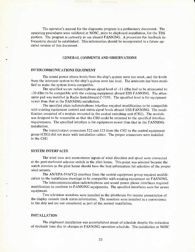
The operator's manual for the diagnostic program is a preliminary document. The operating procedures were validated at NOSC, prior to shipboard installation, for the TDS portion. The program is currently in use aboard FANNING. A procedure for feedback in- formation should be established. This information should be incorporated in a future up- dated version of this document.
GENERAL COMMENTS AND OBSERVATIONS
INTERCOMMUNICATIONS EQUIPMENT
The sound power phone levels from the ship's system were too weak, and the levels from the intercom system to the ship's system were too loud. The intercom has been modi- fied to make the system levels compatible.
The specified secure radiotelephone signal level of-11 dBm had to be attenuated to -20 dBm to be compatible with the existing equipment aboard USS FANNING. The atten- uator pad was installed in Radio Switchboard C-7595. The specified level is for equipment newer than that in the FANNING installation.
The specified plain radiotelephone interface required modification to be compatible with existing equipment control and status signal levels aboard USS FANNING. The modi- fication consisted of a module mounted in the central switching unit (CSU). The module was designed to be removable so that the CSU could be returned to the specified interface requirements. The specified interface is for equipment newer than that in the FANNING installation.
The input/output connectors J22 and J23 from the CSU to the central equipment group (CEG) did not mate with installation cables. The proper connectors were installed in the CSU.
SYSTEM INTERFACES
The wind vane and anemometer inputs of wind direction and speed were connected at the port-starboard selector switch in the pilot house. This point was selected because the watch standers in the pilot house should have the best information for selection of the proper wind sensors.
The AN/UPA-59A(V2) interface from the central equipment group required modifi- cation to the installation drawings to be compatible with existing equipment on FANNING.
The intercommunication radiotelephone and sound power phone interfaces required modification to conform to FANNING equipments. The specified interfaces were for newer equipment.
Two television monitors were installed in the pilothouse for remote presentation of the display console track status information. The monitors were installed as a convenience to the ship and are not considered as part of the normal installation.
INSTALLATION
The shipboard installation was accomplished ahead of schedule despite the reduction of dockside time due to changes in FANNING operation schedule. The installation at NOSC
33

with interconnecting cables provided for shipboard installation pointed out many of the cable problems normally associated with an installation and facilitated the actual ship- board installation.
The problem of wrong sized and missing parts in the installation kits, pointed out earlier, should not occur in future installations.
The realignment of the basic display unit (BDU) rails after the removal of the BDUs for installation will require special alignment jigs. The misalignment of the rails has not occurred in any other installation.
OMR SUMMARY
Tables 1-5 summarize the Operational Maintenance Reports (OMR), grouped by the individual equipments.
Table 1. Console 1, 1641040-101.
Date RTM OMR No Symptoms and Remarks
3 May 78 594 20 632 Faulty sweeps in negative X direction in RAC. Suspect pinched wire between A2A1A6A49 and A2A1A5A22.
3 May 78 594.5 20 634 Unable to extinguish data on CRO with brightness control. Internal adjustment, R133.
3 May 78 594.5 20 635 Console goes into overtemp, then shuts down. Sensor wiring error.
19 May 78 711 20 647 Assorted labels have bad registration or won't flip.
10 Jul 78 1020 20 660 Installed ECA Q33.
11 Aug 78 1212 20 678 Installed compass rose bezel.
14 Aug 78 1224 20 679 LSB of range readout not suppressed in miles position.
21 Aug78 1268 20 681 No +15 V from CRO power supply.
5 Sep 78 1330 20 697 Broken SIF gate. ROM 144 gives intermittent signal when hot.
13 Sep 78 1377 21003 Label at row 1 col 5 won't flip. Arm out of adjustment.
18 Sep 78 1400 20 700 Reconfiguration change and ECA modification.
2 Nov 78 1587 21045 Removed compass rose bezel.
20 Nov 78 1736 21008 Faulty sweeps and no X deflection. Reseated cards at locations A1A13, A1A14, A1A15, A1A20 and A2A32 in electronics drawer.
2 Dec 78 1889 21009 Replaced CCAEP switch modules.
7 Dec 78 1955 21010 CCAEP light bulb burned out, lamp 4 in switch 2.
21 Dec 78 2044 20 692 Symbol intensity pot scratchy, replaced.
8 Jan 79 2121 20 693 Coffee spilled on CCAEP and keyboard; cleaned.
34

Table 2. Console 2, 1641040-100.
Date RTM OMRNo Symptoms and Remarks
15 Feb 78 250 20 624 LED in CCAEP burned out. Resistor shorted while installing labels.
5 May 78 630 20 640 Extra character inserted at row 0, col 64 in 32 X 64 CRO format. Isolated to 199 card at A3A1A13.
11 May 78 674 20 651 CCAEP FEBs inoperative. Repaired broken wire.
16 May 78 715 20645 CCAEP FEBs inoperative. Shimmed lower left corner of face plate.
17 May 78 731 20 646 Pairing line segments have intermittent jitter when pair- ing lines are used in continued line segments. Suspect 235cardatA2A2A13.
22 May 78 740 20 648 Console lamps go out when the CRO drawer is pulled out. Rerouted CRO drawer power wires away from chilled water lines.
31 May 78 853 20643 No symbols displayed. Repaired broken wire to A2A2A4.
1 Jun 78 859 20644 CCAEP row 1 col 3 cue light on all the time. Re- soldered feed-through on circuit board.
21 Jun 78 984 20 652 No standard sea leaders. Adjustable air leaders override sea leaders in any air leader switch position. Symp- toms disappeared when 259 card placed on extender.
21 Jun 78 986 20 653 Console suddenly dead. No sensor, no symbols, no CRO display. Main power on but no +5 V dc. Trouble disappears when console reset.
26 Jun 78 1008 20 653 Installed ECAQ28.
5 Jul 78 1050 20 656 All symbols switch lamps (2) burned out. Replaced with lamps provided by HAC.
5 Jul 78 1051 20657 Installed ECA Q29.
5 Jul 78 1051 20658 Installed ECA Q37.
10 Jul 78 1072 20 659 Installed ECA Q33.
19 Jul 78 1124 20 670 CRO flat cable A3A1J1 and A3A1J2 rub against the PCcardatA3AlAl.
21 Jul 78 1140 20671 BDU trimpot R8 on 183 card at A1A1A9 connecting wires loose. Replaced.
9 Aug 78 1245 20 672 S/S local lamp burned out in cat/sel panel.
35

Table 2. (Contd)
Date RTM OMRNo Symptoms and Remarks
9 Aug 78 1245 20 673 S/S remote lamp burned out in cat/sel panel.
9 Aug 78 1245 20 674 Air/frnd inte lamp burned out in cat/sel panel.
10 Aug 78 1260 20 680 Clear lamp burned out in cat/sel panel.
10 Aug 78 1260 20 687 DS-5 burned out.
10 Aug 78 1260 20 688 DS-8 burned out in display control panel.
11 Aug 78 1270 20 675 +5 V dc power supply bad in console electronics drawer.
11 Aug 78 1273 20 676 Monitor meter reads low, replaced.
9 Sep 78 1399 21002 DS-1 burned out in console electronics drawer.
7 Sep 78 1413 20691 Label sets row 2 col 4 won't flip. Broken arm.
15 Sep 78 1459 20 699 Configuration change and ECA modification.
28 Sep 78 1490 21004 No IDR until console electronics drawer pulled out. Conductor pulled out of J2B03.
4 Oct 78 1518 21006 Flat cable damage (W108) console electronics drawer.
10Oct78 1518 21007 Damaged flat cables during installation.
20 Nov 78 1782 20 694 CCAEP had shorted wire; repaired.
2 Dec 78 1930 20 695 Replaced CCAEP switches.
5 Dec 78 1947 20 696 Coffee spilled on category select panel; cleaned up.
Table 3. Central equipment group.
Date RTM OMRNo Symptoms and Remarks
20 Apr 78 N/A 20 628 Cooling water caps not in the CEG installation kit.
20 Apr 78 N/A 20629 Center mounting screws in connectors Al, A2, and A3 not in CEG installation kit.
20 Apr 78 N/A 20 630 Back panel connecting bolts for CEG back panels A8A11, A8A12, A8A13, A8A14, A8A15, and A8A16 too long.
4 May 78 599 20636 Console 1461080-100 would not respond to interroga- tion when console 1641080-101 was turned off.
4 May 78 411 20 637 Radar sweep rotates erratically. Caused by 238 card at A1J22. Exchanged 238 cards at A1J22 and A1J2.
36

Table 3. (Contd)
Date RTM OMRNo Symptoms and Remarks
5 May 78 622.5 20638 Cabinet power lamp out on power control panel. Replaced lamp.
5 May 78 622.5 20 639 +28 V dc power lamp out on power control panel. Replaced lamp.
9 May 78 633 20 641 Input data bit 9 in CIU 1 in CDB bad. Removed solder splash on 309 card at A2J16.
29 Jun 78 877 20 655 CIU 2 in CDB bad. Input data bits (15-19) not present. Exchanged 195 cards at A5A2A24 and A5A2A27. Trouble corrected.
12 Jul 78 1027 20 669 CIU 2 in CDB, data bit 25 intermittent.
28 Sep 78 1388 21005 Completed ECA Q5984252.
5 Sep 78 1492 21001 +28 V dc lamp on power control panel burned out. Replaced lamp.
Table 4. Intercom (CSU).
Date RTM OMRNo Symptoms and Remarks
28 Jul 78 1 20 677 Remote intercom unit would not initiate. Replaced intermittent connector.
7 Aug 78 1 20 689 Intercom radio output level for red radio channels attenuated to meet shipboard requirements.
8 Sep 78 71.5 20 690 I/O connectors J22 and J23 do not mate with con- nectors on cables from CDB.
2 Jan 78 589 21046 Installed I/O connectors J22 and J23.
Table 5. Digital Card Tester HC-192.
Date RTM OMRNo Symptoms and Remarks
8 Sep 78 20 683 No fans. Card reader will read in only one direction. Inverter card 361350-011 replaced.
8 Sep 78 20 684 Magnetic card reader head will not move forward or reverse. Lubricated.
9 Dec 78 21044 Card adapter would not lock in place. Replaced missing bolt and nut.
37

ONBOARD SPARES
The AN/UYQ-21 interim spares are aboard in storage provided with the installation. The remaining installation and checkout spares were retained at NOSC.
The AN/UYK-7, OJ-172, and AN/UYA-8 spares were provided on the basis of the recommended 2000-hour support list. The spares are in storage provided with the installation.
SYSTEM TEMPERATURE ELEVATION
The AN/UYQ-21 system cooling water temperature was elevated to 40°C (104°?) during the period 3 May 1978 through 27 September 1978. The equipment hours of opera- tion during this period were as follows:
Console 1641040-100 (PPI-2) 876 h
Console 1641040-101 (PPI-1) 819h
Central equipment
Sensor converter group (A-1) 1018h
Switchboard, passive (A-2) 1015h
Switchboard, video (A-3) 1019h
Central data buffer (A-5) 996 h
Power control panel (A-6) 1022 h
The existing chilled water system was modified to maintain the required tempera- ture. The modification consisted of adding a 15-gallon electric water heater in the supply side of the cooling water, installing a thermostat in the water chiller to accommodate the 104oF temperature, and installing a flowmeter at the inlet to console PPI-1. The flow rate was 4 gallons per minute.
The temperatures of the circulating water, cold plates, and power supplies were measured by using a digital readout temperature indicator, DIGITEC 590TC, with a Doric multiport selector and a RUSTRAK recorder.
The RUSTRAK recorder monitored the inlet water temperature to console PPI-1. Seven other temperatures were measured and logged with the multiport selector and the digital readout temperature indicator. The following is a list of monitored points:
Inlet water lo console PPI-2
Electronics drawer power supply in PPI-2
Inlet water to the central equipment group
Outlet water from the central equipment group
Central data buffer power supply
Radar azimuth converter power supply
Electronics drawer power supply in PPI-1
38

Temperature sensitive strips, Tempilabel 8MA-100/38, were placed at various loca- tions in the display consoles and the central equipment group. The following maximum temperatures were indicated:
Central equipment group
Sensor converter group (Al) power supply cold plate
Switchboard (A2) power supply cold plate
Switchboard (A3) power supply cold plate
Central data buffer (A5) power supply cold plate
Display console 1641040-100
Console electronics drawer power supply cold plate
Console electronics drawer card box cold plate
Basic display unit card box cold plate
Basic display unit deflection ampl cold plate
CRO power supply cold plate
Display console 1641040-101
Console electronics drawer left power supply
Console electronics power supply cold plate
Console electronics drawer card box cold plate
Basic display unit power supply
Basic display unit card box cold plate
Basic display deflection ampl (A3) cold plate
Basic display deflection ampl (A4) cold plate
CRO card box cold plate
CRO power supply cold plate
DIAGNOSTIC PROGRAMS
The system diagnostic program was delivered and certified with the AN/UYQ-21 system while it was installed at NOSC. 100 faults were inserted for detection and isolation to a maximum card group size of 10 cards. All of the faults were detected; 98% were isolated.
The test for circle accuracy was not passed by either console. The circle generator card (1640189-100) is being modified. The circle accuracy before modification is more than sufficient for the operational demonstration program.
The limited maintenance program provides a quick check of all gross system func- tions. Troubleshooting aids of preformed messages using the DEAC and a test message generator (TMG) are operated from the console keyboard. The TMG was used during the maintenance training course as a troubleshooting aid.
39
Temperat ure 0C "|;
49 120
49 120
49 120
49 120
66 150
54 130
49 120
54 130
49 120
71 160
66 150
60 140
60 140
49 120
54 130
49 120
49 120
49 120

ANALOG AND DIGITAL TEST SETS
The analog module test set (AMTS) provides a means of dynamically testing the analog cards and modules. The use of the AMTS appears to be time consuming for personnel not completely familiar with the test procedures. In any future training pro- grams, the students should use the AMTS with circuit cards and modules to become completely familiar with the AMTS operation. The test procedures for the AMTS were not available during the period of maintenance training at NOSC.
The digital test set provides a method of dynamically testing the digital cards. The use of the test set is straightforward and very easily understood. The matching of test programs with printed circuit cards in various stages of modification is a potential problem area.
INSTALLATION DRAWINGS
The installation plan for USS FANNING had various changes and errors, as would be expected. The plans should be very carefully updated to aid in future installations.
SUPPORT EQUIPMENT
The support equipment consists of a single-bay AN/UYK-7 computer, a Digital Equipment Auxiliary Console (DEAC) OJ-172/UYK, and Digital Data Conversion Group AN/UYA-8 (IC KCMX). The DEAC and IC KCMX were returned to the manufacturer for refurbishment. The IC KCMX is a prototype version; the only support documentation resides with the equipment on FANNING. A preventive maintenance schedule will be developed by the ship. The AN/UYK-7 computer was dismantled and inspected at NOSC by a factory representative and DL Ream of NAVSEC, with satisfactory results.
An on-call contract exists with UNIVAC for any necessary maintenance support of the support equipment. The response time is 24 hours when the system is in port at San Diego.
MICROMINIATURE REPAIR STATION
A microminiature (2M) repair station was installed as part of the AN/UYQ-21 installation. Two technicians aboard FANNING are certified for 2M repair. The station is used for repair of all printed circuit cards on FANNING.
CONCLUSIONS
DIGITAL ASSEMBLY TESTER
All procedures were tested, with six failures and one provisional pass. The seven procedures were reviewed with the contractor. The required documentation changes and test reprogramming will be completed prior to OPEVAL.
40

The digital test set is a very useful tool for the technician. The practical use of the test should be incorporated in future maintenance courses for the AN/UYQ-21 system.
DISPLAY CONSOLES
All tests were completed, with two failures in each console. The failures of circle accuracy and video selection status are being corrected by modifications.
The computer controlled action entry panel operation was satisfactory after switch modules of the production type were installed. The label registration will be improved with a new set of properly punched film chip labels.
The console has had coffee spilled on the bullnose twice since its installation on USS FANNING. The category select switches and the keyboard required removal and cleaning by the technicians. This will be a continuing problem in all installations.
The intercom headset and sound power phone connectors in the bullnose are located in a position where they can be damaged accidentally by the opening or closing of the electronics drawer. The connectors should be relocated to eliminate the possibility of damage.
After removal of the BDUs for installation aboard USS FANNING, alignment of the basic display unit (BDU) rails required alignment jigs. Alignment jigs should be available at installing activities for future installations.
INTERCOMMUNICATION SYSTEM
AN/UYQ-21 data display group intercommunications system Test 112 was com- pleted with one failure and one error. The failure occurred in the dimmer control - the indicator intensities were incorrect at low intensity levels. The error occurred in the sound power intercommunication test - the audio level was too low when two or more stations depressed the push-to-talk switch. The indicator intensity failure does not occur in a normal operating condition. The low sound power level was corrected by circuit card modification.
Intercommunication system Test 201 was completed with no failures. The tests were conducted with the nonmilitarized power supply. The militarized power supply will be installed and checked prior to OPEVAL.
The sound power phone signal levels were modified to be compatible with the ship's system prior to final testing.
The radiotelephone signal levels and control/status levels were specified for future equipment. Modifications were required to accommodate the existing requirements of USS FANNING. The modifications were installed in the system as stand-alone modules so that the system could be returned to the specified levels by disconnecting and removing the modifications.
ANALOG MODULE TEST SET
The analog module test set (AMTS) was delivered during the final installation and checkout phase. Delivery at that late date precluded testing prior to installation. Valida- tion of the test procedures was conducted when the system was available. The operation schedule of USS FANNING would not permit the completion of testing prior to OPEVAL.
41

The AMIS was moved from USS FANNING to NOSC for completion of testing of 22 procedures. The analog cards and modules used were from depot spares and AN/UYQ-21 equipment at NOSC.
Testing of the procedures will be completed prior to OPEVAL.
TRAINING
Maintenance training consisted of formal classroom lectures and actual equipment for operation and troubleshooting. The test procedures for the digital and analog test sets were not available for practical application during the time the course was conducted. Both the theory of operation and demonstration of the test sets were included in the maintenance course.
The maintenance course as taught at NOSC is considered adequate in content and format except for the practical use of the analog and digital test sets.
The operator training courses consisted of formal lectures and actual system opera- tion using the operational demonstration program with live radars. The first course was 3 weeks long. After its completion, both the class and the instructor felt that 2 weeks would be sufficient time for the course. The length of the second course was thus reduced to 2 weeks.
The operators were given additional refresher training underway after the system was installed aboard ship. The operational system was used during USS FANNING re- fresher training.
The operators' course in conjunction with the underway refresher training is considered adequate.
MICROMINIATURE REPAIR STATION
The Microminiature (2M) repair station was installed as part of the AN/UYQ-21 installation to support the on-board repair of printed circuit cards. Two USS FANNING technicians attended the 2M course and were certified as 2M repairmen. The 2M station is considered adequate and will be utilized for the repair of all printed circuit cards on USS FANNING.
SOFTWARE
The following programs were provided with the AN/UYQ-21 installation:
Operational demonstration
Limited maintenance tests
AN/UYQ-21 diagnostics
AN/UYK-7 diagnostics
OJ-172(V)/UYK I/O console POFA
CGN 38 class utility package
42

The operational demonstration program was designed to support the AN/UYQ-21 operational evaluation and should not be considered as a full NTDS operational program.
The operational demonstration program trouble reports that were generated during operational testing have been reviewed by FCDSSA and NOSC. The status of actions taken were discussed with USS FANNING personnel and the results were demonstrated.
The programs provided are considered adequate for the support of the AN/UYQ-21 system and are operating satisfactorily.
RECOMMENDATION S
Issue a certificate of readiness for operational evaluation of Computer Display Set AN/UYQ-21.
43

APPENDIX A: AN/UYQ-21 TECHEVAL STATUS
45

From: To:
Subj:
Ref:
DEPARTMENT OF THE NAVY NAVAL OCEAN SYSTEMS CENTER
SAN DIEGO, CALIFORNIA 92152 IN REPLY REFER TO;
CCC:mrh 3900:0021 Ser 824/1?
30 JAN 1979 Commander, Naval Ocean Systems Center Commander, Naval Ships Engineering Center (NAVSEC 6172B)
AN/UYQ-21 Technical Evaluation (TECHEVAL) Status
(a) TECHEVAL Test Report for AN/UYQ-21 Computer Display Set, Rough Draft, 12 Jan 1979
1. Formal TECHEVA1 testing of the AN/UYQ-21 Computer Display Set was completed on 12 January 1979. Reference (a) reported the test results as of that date. Some tests had not been completed at that time, and other tests identified problems that required correction prior to the start of 0PEVAL. This letter reports the status of previously uncom- pleted tests and the actions taken to correct identified problems, referenced by paragraph numbers in reference (a),
2. Paragraph number 5.6.4. Test number 105, paragraph 7.1, step 19 was performed successfully with the bearing circle removed.
3. Paragraph number 5.11.4. Reprogramming and testing of five of the six previous failures has been completed. The remaining failure (1640237-100, Line and Leader Control) and the provisional pass (1640245-100, Digital Rate Multiplier) have been reprogrammed and will be retested prior to 12 February 1979.
4. Paragraph 5.14.4. To facilitate the testing of the Analog Module Test Set and procedures, the test set was moved to NOSC while the USS FANNING (FF1076) was underway on operations. Due to these operations PC cards were not available to test two procedures. These procedures are being tested at this time. Forty other procedures have been tested and twenty-nine have been verified. Eleven procedures failed verification. Of these eleven, five have been revised and are awaiting verification. The remaining six failures are being revised at this time. All procedures are expected to be verified, and the test set moved aboard FANNING, prior to 12 February 1979. Summary of unverified procedures.
390532 CR0 CRT Assembly 1621865 Deflection Amp 1635006 Audio Buffer 1635017 Power Converter 1640171 Video Gamma Compensator 1640173 Serial Console Transceiver 1640174 Deflection Pre-Amp
Revised Under Revision Under Test Under Test Revised Revised Revised
46

1640179 Intensity Compensating Amp 1640183 Summing Deflection Amp 1640186 Raster Control Assembly 1640193 Multiplexer Sweep Driver 1640199 CRO Memory 1640238 Synchro-to-Digital Conv.
Under Revision Revised Under Revision Under Revision Under Revision Under Revision
5. Paragraph 5.15.4. Modification of the Circle Generator Card was accomplished and the required tolerances were achieved. The modi- fication to the Video Selection Switch, to eliminate a wrong status code being generated, is available and will be installed prior to 12 February 1979.
6. Paragraph 5.23.4. The sensitivity of the input to the Ships Motion Converter was increased to correct the intermittent signal problem. With the Ships Motion Converter operating properly it was tested, and the test results were satisfactory.
7. This letter will be included as an appendix of reference (a).
•v c i(M- RV. C. Kolb By direction
Copy to: NAVSEC 6172B (CDR D. L. Leichtweis) 2 cys
47

INITIAL DISTRIBUTION
NAVAL SHIP ENGINEERING CENTER NSEC-6172B NSEC-6178.03 (F. A. RUSSELL) NSEC-6I78.03 (C. BEDORE) NSEC-6178.03 (T. H. MURPHY)
(6)
COMMANDER OPERATIONAL TEST AND EVALUATION FORCE (2)
DEPUTY COMMANDER, OPERATIONAL TEST AND EVALUATION FORCE, PACIFIC (2)
NAVAL SEA SYSTEMS COMMAND NSEA-03416 (P. J. ANDREWS)
HUGHES AIRCRAFT CO. AN/UYQ-21 PROJECT MANAGEMENT OFFICE DATA PROCESSING PRODUCTS DIV. P.O. BOX 3310 FULLERTON, CA 92634
(3)
DEFENSE DOCUMENTATION CENTER (12)

R 58546