
UNCLASSIFIED - Defense Technical Information...
19
UNCLASSIFIED ADi 27 3 413 ARMED SERVICES TECHNICAL INFORMAON AGENCY ARLINGTON HALL STATION ARLINGTON 12, VIRGINIA UNCLASSIFIED
Transcript of UNCLASSIFIED - Defense Technical Information...

UNCLASSIFIED
ADi 27 3 413
ARMED SERVICES TECHNICAL INFORMAON AGENCYARLINGTON HALL STATIONARLINGTON 12, VIRGINIA
UNCLASSIFIED

NOTICE: When government or other drawings, speci-fications or other data are used for any purposeother than in connection with a definitely relatedgovernment procurement operation, the U. S.Government thereby incurs no responsibility, nor anyobligation whatsoever; and the fact that the Govern-ment may have formulated. furnished, or in any waysupplied the said drawings, specifications, or otherdata is not to be regarded by implication or other-wise as in any manner licensing the holder or anyother person or corporation, or conveying any rightsor permission to manufacture, use or sell anypatented invention that may in any way be relatedthereto.
61-179
C1'U-m
PUMP VIBRATION CAUSED BY CAVITATION
BY
Cft~j G. A. Khoroshev

MY-T- 1w 2/+4
UNEDITED ROUGH DRAFT TRANSLATION
PumP VIBRATON CAUSED BY CAVITATION
By G. A. Thoroshev
English Pages: 15
Source: Energomasinostroyeliye, No. 4f,April 1960, pp 26-30
sc-862sqv/11lI-6o-o-4-5/9
TIMS TRANSLATION 1S A RENDITION OF THE ORIGI-NAL PORINN TEXT WITHWUT ANY ANALYTICAL OltES1ITOMIAL CUMMNT STATEMNNTS ON THEO0IE5 PRPRsBYsADVOCAT011011PUU ARE THI OF THE SOURCIIASS 00 OT 111CSRIILY REFLECT THE POSTION TRANSLATION SERYIES BRANHOR OPIIO OF THEI POISHM TECHNOLOGY DO- PORIN TECIPSIOLOGY DIVIIO
ViSION. MAPS, OHIO.
ffe1TT- 61-l79/1+2+4 hb20 Feb__162
P

PUMP VIBRATION CAUSED BY CAVITATION
G. A. Khoroshev
The problem of pump vibration caused by variousstages of cavitation is examined. The influenceof the air content of liquid on the intensity andfrequency of vibration is established.
The relation of the collapsing cavitation to aheavy increase of vibration in the average audio-frequency range is indicated. Measures for theprevention of vibration over the entire audio-frequency range are described.
One of the most important problems of hydraulic-machine design
is the prevention of vibration. In the literature primary attention
is given to vibration caused by unbalanced rotary masses. This
vibration has a maximum amplitude at the rotation frequency f, = n6o
cps (where n is the rpm) and can be significantly reduced by
more careful installation and production of the rotary parts of the
machinery. However, experience with various hydraulic machines
(hydro turbine, centrifugal, fan and screw pumps) indicates that in
several working regimes additional-frequency vibration develops,
the amplitude of which greatly exceeds the vibration amplitude at the
rotation frequency [1]. Such vibration not only causes fatigue
effects in various parts and units Df the machinery, but sometimes
ITD-TT-61-179/1+2+4 -1-

leads to serious accidents. The cause of these intensive vibrations
is assumed to be cavitation. Intensive studies [1], [2], and [3]
have been devoted to the fight against cavitation and its destructive
activity, but none of them has paid sufficient attention to the
relation of the development of vibration to the degree of cavitation
and the properties of the fluids pumped. The lack of such information
prevents the development of effective measures for the elimination,
or even the partial reduction of this vibration. The author investi-
gated a series of centrif gal pumps. The qualitative picture of the
occurrence of vibration from cavitation (within certain limitations)
can be extended to all hydraulic machinery.
Centrifugal pumps of various design, sizes and speeds were
investigated. Special testing equipment allowed us to conduct complex
tests of pumps with open and closed cycles. An air spray device fitted
to the intake pipe made it possible to alter the proportions of the
dissolved and diffused air in the water. Cavitation was measured by
constructing cavitation characteristics and completed by visual ob-
servation and from marks left by cavities on the vanes of the
impellers. The vibration was measured on the spi.ral cam and lug of
the pump by vibration pickups possessing a linear characteristic
which extends over the entire audio-frequency range. Vibrations up
to 8000 cps were analyzed by an acoustic device with a three per cent
bandwidth pass. The general level of vibration was measured in two
broad frequency bands: 25 to 1000 cps and 25 to 20,000 cps.
Together with spectral analysis and visual observations, this permits
us to determine the influence of cavitation on the vibration spectrum
and to develop means for combatting this vibration.
FTD-TT-61-179/+2+4 -2-

4N :f, e,38 -
102A
ovirtio pu at o. /1 ofv aio ppNOf
94 n Z v i
82 cyto lo0 0O 078 . h-d7A
2 3 4 6 10 0 X M 5A' V70 2 $ -1 6 5 1 10 2 5
Fig. 1. The general level Fig. 2. The general levelof vibration pump No. 1 of vibration pump No. 2( RK-2) n .2730 rpm vs. (RK-5) n- 14100 rpm vs.the magnitude of the cay- the magnitude of cavita-itational reserve during tional reserve duringclosed cycle tests. closed cycle tests.
In Fig&. 1 and 2 the relationship of the general level of vibra-tion to the magnitude of cavitational reserve (Ah) for two centrifugal
pumps which differ in weight and number of rotations is plotted.
Analysis of these curves together with visual observations indicates
that there are two phases of cavitation: air and steam cavitation.
Air cavitation is connected with the separation of air in eddies
and eddy zones which are formed in the flow channels as a result of
the flow break away from the surface of the vanes, and the presence
of surface cracks as the flow descends from the vanes and the pres-
ence of an axial eddy in the inter-blade channels, etc. During the
operation of the pump the extent of eddy formation can be so great
that even at excessive suction pressure the pressure in the eddies
can fall below the air saturation pressure of water. As a result of
this air bubbles which move with the flow will form in the center of
the eddies. Under the influence of changing internal and external
FTDTT-61-179/1+2+. -3-
forces they radiate very strong vibrations over a wide frequency band,
which cause the vibration of the casing of the pump.
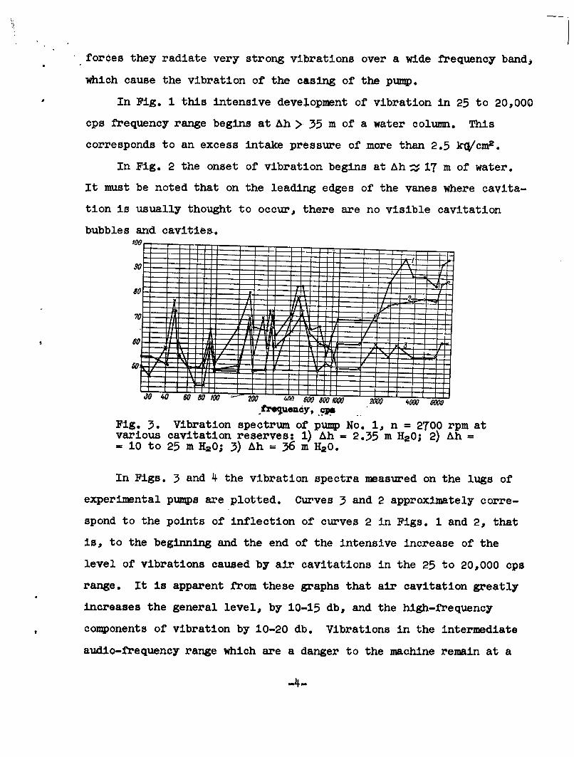
In Fig. 1 this intensive development of vibration in 25 to 20,000
cps frequency range begins at Ah > 35 m of a water column. This
corresponds to an excess intake pressure of more than 2.5 k0/cm:.
In Fig. 2 the onset of vibration begins at Ah % 17 m of water.
It must be noted that on the leading edges of the vanes where cavita-
tion is usually thought to occur, there are no visible cavitation
bubbles and cavities.
0 t3 3--"
60"--
JO 4 000 o 800 IO00 2000 4000 &000. '" Uendy, .c
Fig. 3. Vibration spectrum of pump No, 1, n = 2T00 rpm atvarious cavitation reserves: 1) Ah = 2.35 m H,20; 2),Ah-= 10 to 25 m H20; 3) Ah = 36 m H20.
In Figs. 3 and 4 the vibration spectra measured on the lugs of
experimental pumps are plotted. Curves 3 and 2 approximately corre-
spond to the points of inflection of curves 2 in Figs. 1 and 2, that
is, to the beginning and the end of the intensive increase of the
level of vibrations caused by air cavitations in the 25 to 20,000 cps
range. It is apparent from these graphs that air cavitation greatly
increases the general level, by 10-15 db, and the high-frequency
components of vibration by 10-20 db. Vibrations in the intermediate
audio-frequency range which are a danger to the machine remain at a
-4-

constant general level (curve 3, Figs. 1 and 2) and at approximately
the same intensity of separate spectral components (curves 2 and 3,
Figs. 1 and 2). The results of these tests allow us to draw two more
interesting conclusions:
1. The different values of Ah at which the intensive vibration
increase begins is determined by the intensity of the eddy formation
which, in its turn, mainly depends on the number of rpm. Actually
pump No. 1 (.see Fig. 1)and pump No. 2 (see Fig. 2) have approximately
the same average flow-channel speeds and cross-sectional speed-
distribution curves, but their rpm speeds are different: pump No. 1
n = 2700 rpm, pump No. 2 n = 1400 rpm. As a result of this difference
the intensive vibration increase begins in pump No. 1 at Ah > 35 m
H20, whereas in pump No. 2 it begins at AhZ 17 m H20.
2. The low intensity of the spectral vibration components in
the frequency range above 1000 cps in pump No. 2 at Ah > 20 m H2 0*
(curve 3, Fig. 4) and in pump No. 1 Ah > 35 m, H20* (curve 3, Fig. 3)
indicates that the vibrations actually caused by eddies, turbulent
flow pulsations, friction and other hydrodynamic forces are of no
importance as independent sources of vibration in pumps and other
hydraulic machines. Eddies and turbulent pulsations can help
increase the vibrations only if air bubbles are formed in them, or
in the fluid. As they move through the channels the bubbles fall
into the eddies under the influence of high local pressure gradients,
they begin to vibrate intensively causing the pump casing to vibrate.
This was checked by injecting tiny air bubbles into the inlet
* A further increase of Ah does not usually cause changes inthe vibration spectrum.
-5-

(suction) pipe of pump No. 2. Then the water was degassed to eliminate
the influence of the dissolved and, consequently, liberated air in
the eddies. At Ah > 10 (Fig. 2, experimental points 4, 5, 6) when
there is no visible cavitation on the leading edges of the vanes, the
injection of a small quantity of air causes a sharp increase (by
5-30 db) of high frequency vibrations.
Generally, no damage was found in flow channels with air oavita-
tion. Vapor cavitation is connected with the formation of air-steam
bubbles and cavities in the immediate neighborhood of the impeller's
leading edges which takes place as a result of a decrease of 'ocal
pressure to the value of the vaporization pressure of the liquid at
the given temperature. Visual observations indicate that the three
stages of vapor cavitation in the pumps can be clearly distinguished:
the incipient stage, the developed stage and the collapsing stage.
70
GC
4'-Fig. 4 Viraio spct0 of pump No. 20 80001400 rpm a
H -different cavitation reserves: 1),&h = 23 m H20; 2) Ah. 10 m H20; 3),&h = 20-30 m H20.
The incipient (visible) vapor cavitation stage depends mainly
on the shape of the leading edges of the vanes and the angle of
attack. This stage of cavitation considerably precedes the stages
which bring about the alteration of the cavitational curves 1, (see
-6-

Figs. 1 and 2). The cavitation area in this instance consists of
tiny bubbles composed primarily of air and steam, which are combined
into a small cloudy band at the leading edges of the vanes. It is
evident from Figs. 1 and 2 that the initial cavitation stage does not
cause a sharp increase of the general level of vibration in the audio-
frequency range. The spectral components measured before and after
the initial cavitation stage also remain unchanged. In this stage
the cavitations radiate ultrasonic vibrations, which can not be
measured by the apparatus used in these investigations.
The developed steam cavitation stage begins with the appearance
of visible cavitation and is assumed to continue until the beginning
of the cavitation curve change (see Figs. 1 and 2). This stage is
characterized by the steady expansion of the cavitation zone over the
entering edges. The general level of vibration in the 25-20,000 cps
frequency range also steadily increases without undergoing sharp
change. The bubbles which are composed mainly of air and steam in
the beginning of this stage, gradually turn into pure steam and the
border of the cavitation area becomes more clearly defined. This is
evidence of the instantaneous collapsing of the small bubbles [I].
During the formation of the pure steam cavitation the amplitude of
vibration depends to a great extent on the degree to which the water
has been saturated with air. The different content of air in water
is the result of the different relationship of the vapor and air
phases inside the bubbles themselves. This accounts for the different
contraction rates of these bubbles. The less saturated the water is
with air, the greater the closing rate of the bubbles and the more
intense the vibration of the pump. Investigations indicate that the
general vibration level of a pump operating with air saturated water
-7-
is always 3 to 10 db lower than a pump using deaerated water. Visual
observations of cavitation on the impeller vanes carried out with
different ratios of air to water prove that the development of cavi-
tation, that is, the area covered by cavitation with the same value
of cavitation reserve Ah, remains constant and does not depend on the
air content of water. It is only the structure of the cavitational
region itself which changes. When the water is saturated with air
the cavitation area is bright white and its edges are washed out,
while further along the stream, separate streamlets with non-collapsed
bubbles can be seen. If the water is deaerated the cavitation area
is transparent and has a sharply defined border as a result of which
the bubbles seem to be collapsing instantaneously. It follows that
the intensity of the vibration depends not only on the dimensions of
the cavitation zone, but also on the relationship of the air and
vapor phases inside the cavitation bubbles themselves.
If the pump pumps air saturated water and has a long inlet
(suction) pipe, air begins to be liberated when the suction pressure
is lower than the atmospheric pressure (that is at Ah > 10 m H20).
At constant high suction pressure this process is stabilized and the
pump actually pumps a two-phase air-water mixture. This phenomenon
can be observed when the sluice valves, cleansing jets, nonreciproca-
ting valves, etc., are adjusted for suction. The presence of dis-
persed air bubbles in the stream of liquid, as well as the dissolved
air in the water leads to a significant reduction of the high fre-
quency vibrations of the pump.
The results of these tests are presented in Fig. 5. Curve 1
represents the averaged curve. Curve 3 represents the general level
of vibrations during tests of pump No. 1 with deaerated water in a
-8-
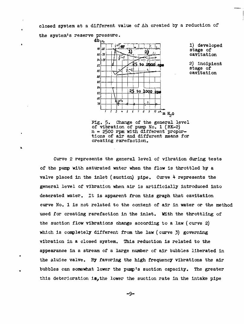
closed system at a different value of Ah created by a reduction of
the system's reserve pressure.db Hn,
dlb--, IT 77 1) developedi stage of
96-28 -" - cavitation
$2 P 2) incipient-- stage of';Z 72 -a 2cavitation
8684-
2 3 4 5 6 7 8 9 fO i,
Fig. 5. Change of the general levelof vibration of pump No. 1 (RK-2)n = 2500 rpm with different propor-tions of air and different means forcreating rarefaction.
Curve 2 represents the general level of vibration during tests
of the pump with saturated water when the flow is throttled by a
valve placed in the inlet (suction) pipe. Curve 4 represents the
general level of vibration when air is artificially introduced into
deaerated water. It is apparent from this graph that cavitation
curve No. 1 is not related to the content of air in water or the method
used for creating rarefaction in the inlet. With the throttling of
the suction flow vibrations change according to a law (curve 2)
which is completely different from the law (curve 3) governing
vibration in a closed system. This reduction is related to the
appearance in a stream of a large number of air bubbles liberated in
the sluice valve. By favoring the high frequency vibrations the air
bubbles can somewhat lower the pump's suction capacity. The greater
this deterioration isthe lower the suction rate in the intake pipe
-9-

and the greater the distance between the pump and the sluice valve.
In one of the pumps the liberation of bubbles in the sluice valve led
to the increase of the critical cavitation reserve (Ahcr) by 0.5 to
0.8 m H20. Change in the structure of the flow entering the pump can
also be produced by artificial air injection. The results of these
tests are given in Fig. 5 (curve 4) and Fig. 6 (curves 3, 4, and 5).
These results indicate that artificial air injection is a very effec-
tive method of combatting high frequency vibrations produced by steam
cavitation. The vibrations were reduced by 5 to 15 db, and even more,
in several instances up to 20 to 30 db. At the same time it is
necessary to determine the maximum air output V which can be approx-
imately expressed in the formula V/Q < 0.002 m/hr (where Q is the
output of the pump m3/hr). An increase of the ratio of air to water
produces an earlier disruption in the cavitation curves and does not
help to reduce vibration. Thus the injection of air into the main
line completely eliminates the vibrations produced by steam cavita-
tion without impairing the cavitational properties of the pumps.40, I,
20 aII
46 go 200 P
'98 _
~!
9?o - - - to 20I" p
88 f-a IT' . - - - -
86 ' -4 - -
84-a8 - - -
82 -f------80\
f 2 3 4 .5 7 8 .9 fo ft. h,m~
Fig. 6. Change of the general level ofvibration of pump No. 2 (RK-4) n = 1400rpm with different proportions of airto fluid.
-10-

At this cavitation stage damage to the flow channels at some
distance from the cavitation zone can be observed. This damage
decreases with the increase of the ratio of air to water. The devel-
oped cavitation stage, like the incipient stage preceding it, presents
no threat to the machine as a whole but it causes intensive damage to
the flow channels and promotes pump vibration, which in a number of
cases it is desirable to limit.
The disruption stage of cavitation is accompanied by a complete
breakdown of pump operations. The cavitation cavities cover a larger
part of the impeller vanes and periodically break away from the vanes
so that the movement of the fluid in the pump assumes a pulsating
character. The entire equipment is subjected to heavy shocks. The
head, the output and the effLciency of the pump fall. The presence
of such a cavitation stage is indicated by a sharp drop of the cavi-
tation curves 1 (see Figs. 1, 2, and 5). The analysis of curves 3
in Figs. 1 and 2 and of curve 5 in Fig. 5 indicates that the general
vibration level in the 25-1000 cps frequency range, within broad
limits, does not depend on the cavitation reserve Ah, the proportions
of fluid and the method of producing rarefaction in the suction stage.
For a given design of pump and rpm it depends mainly on the amplitude
of the mechanical sources of vibration. In this frequency range
cavitation is a source of vibration only under disruptive operating
conditions or those close to them.
Investigations indicated that a marked increase of vibrations
in the 25 to 1000 cps frequency range is definitely related to the
disruption cavitation stage &h as determined by the cavitation curve
1 in Figs. 1, 2 and 5. The intensive vibration increase always
begins sooner than cavitation curves 1 commence to drop.
-11-

TABLE
Coefficients of Reserve T
pump No. Pump No.2
rpm RK-1 RK-2 rpm RK-3 RK-4
1.26 1.15 1.32 1.2208Qecfc 2500 1200
Qspecific 1.20 1.15 1.19 1.44
1.2Qspecific 1.32 1.10 1.38 1.58
0.8Qspecific 1.27 1.17 1.27 1.39
Qspecific 2700 1.25 1.10 1400 1.28 1.36
1 .2 Qspecific 1 .21 1.17 1.23 1.35
In the table the relationship of the critical cavitation reserve
Ahcr to the cavitation reserve Ahv corresponding to the onset of the
increase of vibrations in the 25 to 1000 cps frequency range is
presented. It is evident from the table that the maximum permissible
cavitation reserve which guarantees the pump production of the re-
quired head characteristics, output, efficiency and the elimination
of vibrations caused by disruption cavitation must be selected with a
30-40% reserve of the tabulated hcr or that determined by the formula
at the given high-speed cavitation coefficient C:
C = 5.62 n fiLAh'hcr
where n is the rpm
Q is the output of the pump
Ahcr [m H2 0] is the critical cavitation reserve
Vibrations causing the disruption stage of cavitation are a
FTD-TT-61-179/1+2+4 -12-

great danger not only to the mechanism as a whole* and to its separate
parts by causing damage to the bearings, abuttments and fixing bolts
[1], but also to structures and substructures at a considerable
distance from the equipment.
There are two reliable methods for combatting such vibrations:
first, by proper adjustment of the operating conditions to the
suction height and second, the improvement of the caviation proper-
ties of the pumps if the suction height is given and it is not
possible to change It. Such an improvement of pump cavitation prop-
erties can be :bro* about mainly by increasing the width of the
impeller inlet by using vanes of double curvature and sickle-shaped
profile.
Concerted application of the above recommendations significantly
improves the cavitation properties of the pumps and thus broadens the
range of the working suction heights.
This picture of the development of vibration caused by cavitation
can be observed in all hydraulic machines. However, each one will
have its peculiarities. For example, in hydroturbine and propeller
pumps cavitation begins at first in the terminal eddy which breaks
away from the vanes. In the beginning air cavitation occurs and It
turns into steam cavitation as the load on the vanes (increase of rpm,
delivery, etc.) increases. The developed stage of cavitations in
this instance is related to the spread of cavitation over the vanes,
and at the moment of disruption one can also observe the cavities
periodically breaking away from the vanes. As a result of this the
whole experiment is subjected to heavy shocks.
* The Vibration amplitude can reach 0.5-1.0 mm and more.
STD-TT-61-179/1+2+4 -13-

Conclusions
1. Air and steam cavitation are a source of intensive vibration
in centrifugal pumps.
2. Air cavitation is related to liberation of the air in the
eddies which break off in the flow channels of the pump and are a
source of high-frequency vibration.
3. Air cavitation consists of three stages: incipient, devel-
oped and disruptive.
4. The incipient steam stage of cavitation does not disturb the
operation of the pump and is a source of ultrasonic vibrations.
5. The developed stage of cavitation is a source of flow channel
damage and intensive high-frequency vibrations. The damage as well
as the vibration can be completely eliminated by changing the ratio
of air to water.
6. The disruptive stage of cavitation is a source of intensive
pump vibration of pumps in the average audio-frequency range.
The amplitude of these vibrations can reach a high value,
threatening the operation of the machine. A method of combatting
these vibrations is the correct selection of suction heights and the
improvement of the suctional properties of pumps.
REFERENCES
1. G. Ter-Akopov, Bor'ba s Xznosom Gidroturbinnogo Oborydovaniyaot Kavitatsil i Nanosov, Gosenergoizdat, 1950.
2. A. A. Lomakin, Tsentrobezhnyye i Propellernyye Nasosy,Mashgiz, 1950.
3. Sbornik Dokladov (Collection of Reports)"Cavitation inHydrodynamics," London, 1956.
4. W. Guth, Zur Entstehung der Stosswellen bei der Kavitation,"Akustica,"V-f. 6, No. 6, 1956.
FTD-TT-61-17 9/1+2+4 -14-

DISTRIBUTION LIST
DEPARTMINT OF DJIBNSE Nr. Copies MAJOR AIR COGWqDS Nr. Copies
AFSCSCFTR 1
HEADQUARTERS USAF ARO 1ASTIA 10TD-Bla 3A.CIN-3D2 1 AFAC (NDF) 1BSD (BSP) 1AFI'TC ( FTY) 1ASD (DCF) IOTHER AGENCIES APswo (swy) 1AEDC (RAY) ICIA 1
NSA 2AID 2OTS 2ABC 2PWS 1POE 1RAND 1
FTD-T- 61-179/1+2+4 15