UNCLASSIFIED AD NUMBER LIMITATION CHANGES · 2018-11-09 · special significance need be assigned...
69
UNCLASSIFIED AD NUMBER LIMITATION CHANGES TO: FROM: AUTHORITY THIS PAGE IS UNCLASSIFIED AD603342 Approved for public release; distribution is unlimited. Distribution authorized to U.S. Gov't. agencies and their contractors; Administrative/Operational Use; AUG 1964. Other requests shall be referred to Air Force Arnold Engineering Development Center, Arnold AFB, TN. dtic form 55
Transcript of UNCLASSIFIED AD NUMBER LIMITATION CHANGES · 2018-11-09 · special significance need be assigned...

UNCLASSIFIED
AD NUMBER
LIMITATION CHANGESTO:
FROM:
AUTHORITY
THIS PAGE IS UNCLASSIFIED
AD603342
Approved for public release; distribution isunlimited.
Distribution authorized to U.S. Gov't. agenciesand their contractors;Administrative/Operational Use; AUG 1964. Otherrequests shall be referred to Air Force ArnoldEngineering Development Center, Arnold AFB, TN.
dtic form 55

AEDC-TDR-64-107 s ~
It.. / f . . . . . . . . . . . . . . . . . . . . . . . . .
UNCLASSIFIED I
STUDY OF ELECTRODE ATTACHMENT REGIONS IN HIGH CURRENT GASEOUS DISCHARGES
By
Dr. Gordon L. Cann
Electro-Optical Systems~ Inc. Pasadena, California
~ C
~ ~ i ('1
w , ~
m
~ >
TECHNICAL DOCUMENTARY REPORT NO. AEDC-TDR-64-107 - . . . . J
August 1964
Program Element 61405014/8951, Task 895101
(Prepared under Contract No. A F 40(600).987 by Electro-Optical Systems, Inc., Pasadena, California.)
ARNOLD ENGINEERING DEVELOPMENT CENTER
AIR FORCE SYSTEMS COMMAND
UNITED STATES AIR FORCE

OTICES Qualified requesters raay obtain copies of th | s report fro:r DDC, Cameron Station, Alexandria, Va. Orders will he expedited if placed through the librarian or other staff member designated to request and receive documents from DDC.
When Government drawings, speci f ica t ions or other data are used for any purpose other than in connection with a definitely related Government procurement operation, the United States Government thereby incurs no responsibi l i ty nor any obligation whatsoever; and the fact that the Government may have formulated, furnished, or in any way supplied the said drawings, specif icat ionss or other data, is not to he regardcd hy implication or otherwise as in any manner l icensing the holder or any other person or corporation, or conveying any rights or permission to manufacture, use , or se l l any patented invention that may in an)" way he related thereto.

A E DC-T D R-64-107
STUDY OF ELECTRODE ATTACHMENT REGIONS
IN HIGH CURRENT GASEOUS DISCHARGES
By
Dr. Gordon L. Cann
E l e c t r o - O p t i c a l S y s t e m s , I n c .
P a s a d e n a , C a l i f o r n i a
(The r e p r o d u c i b l e s u s e d i n t h e r e p r o d u c t i o n o f t h i s r e p o r t w e r e s u p p l i e d by t h e a u t h o r s . )
A u g u s t 1964
AF - AEDC & r r , ~ d A PS " r am

A EDC-TDR-64-107
FOREWORD
This report was prepared by Dr. Gordon L. Cann and Mr. Robert L.
Harder of the Fluid Physics Division of Electro-Optical Systems, Inc.~
under USAF Contract No. AF 40(600)-987. The report covers research
conducted from 18 June 1962 through 18 September 1963.
3240-FINAL

AEDC-TDR-64-107
ABSTRACT
This report discusses an experimental and theoretical study of
electrode attachment regions in a high-current gaseous discharge~
particularly in the mechanisms causing retrograde motion of the arc
attachment spot on the cathode. Work included mathematical analysis
and formulation of a theory of cathode emission under these operating
conditions and experimental investigations to correlate the theory
with observed effects.
Experiments and apparatus for measuring power loss to arc cathodes
were set up. Analysis of the retrograde motion of the cathode spot was
made~ and experiments to confirm the analysis were performed.
The study has resulted in the definition of a mathematical problem.
The MHD equations must be solved in the electrode and in the gas~ and
the two solutions matched at the interface.
PUBLICATION REVIEW
This report has been rev iewed and publicat ion is approved.
Capt, USAF Aerospace Sciences Division DCS/Research
V

A I= DC-T D R -64-107
l,
2.
.
.
.
J
7.
TABLE OF CONTENTS
INTRODUCTION
ELECTRODE ATTACHMENT REGIONS IN HIGH CURRENT DISCHARGES
2.1 Statement of the Problem
2.2 Mathematical Formulation of the Problem
ENERGY BALANCE
3.1 Energy Balance in the Metal
3.2 Heat Balance in an Arc Near the Attachment Point
3.3 Heat Balance at the Cathode Surface
3.4 Heat Balance at the Anode Surface
CATHODE SPOT EXPERIMENT
4.1 Test Geometry
4.2 Instrumentation
4.3 Experimental Results
RETROGRADE MOTION OF THE CATHODE SPOT
5.1 Analysis of Retrograde Effect
5.2 Retrograde Motion Experiment
CONCLUSIONS
RECCLMMENDATIONS
REFERENCES
Page 1
2
2
5
12
12
21
26
31
34
34
39
39
43
43
48
56
57
58
3240-FINAL
vii

AEDC-TDR-64-107
LIST OF FIGURES
22
Table I
1 Postulated Cathode Mechanisms
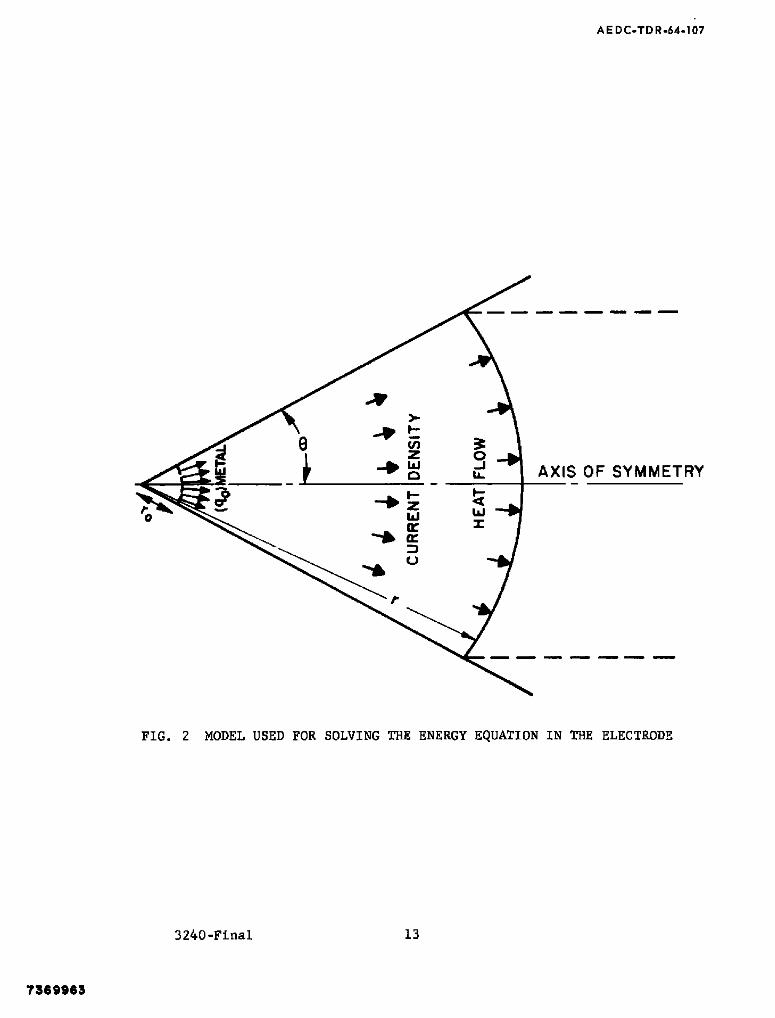
2 Model Used for Solving the Energy Equation in the Electrode
3 Thermal Conductivity Integral vs Temperature for Tungsten (Determined from Data of Ref. 4) 15
4 Thermal Conductivity Integral vs Temperature for Copper (Determined from Data of Ref. 4) 16
5 Electrical Resistivity of Tungsten vs ~ (Determined from Data of Ref. 4) 17
6 Electrical Resistivity of Copper vs ~ (Determined from Data of Ref. 4) 18
7 Model Used for Solving the Energy Equation in the Gas 22
8 Dimensionless Conductivity Integral in Arc vs Distance from Cathode Surface 25
9 Vapor Pressure and Thermionic Emission Current Density for Tu.gsten (Determined from Data of Ref. 5) 29
I0 Vapor Pressure and Thermionic Emission Current Density for Copper (Determined from Data of Ref. 5) 30
Ii Theoretical Solutions for Tungsten Cathode 32
12 Theoretical Solutions for Thoriated Tungsten Cathode 33
13 Schematic Drawing of Cathode Test Apparatus 35
14 Early Arc Cathode Assembly 36
15 Components for Arc Cathode Study 37
16 Assembled Equipment for Cathode Study 38
17 Cathode Attachment and Column During Operation 40
18 Comparison of Measured and Theoretical Values for Cathode Power 41
19 Retrograde Motion Experimental Apparatus 50
20 Retrograde Motion Apparatus Magnetic Circuit Components (Disassembled) 51
21 Retrograde Motion Apparatus Magnetic Circuit Components (Assembled) 51
Magnetic Circuit Retrograde Motion Apparatus - Phase I 53
Instruments Used in Cathode Spot Experiment 42
6
13
3240-FINAL
vi i i

A EDC-TDR-64-107
LIST OF SYMBOLS
A
B
C
D
E
le! F I
!
F I
F 2
f
h
I
J
Cross-section Area
Magnetic Field
Constant Defined by Equation (64)
Particle Diffueion Coefficient
Electric Field
Charge of an Electron
Defined in Equation (57)
F I - VxB
Defined in Equation (58)
Correction Term in Diffusion Coefficient
Planck's Constant
Total Current
Charged Particle Flux
Jo(),Jl( ) Bessel Functions
# J
K
k
L I
M
Ill e
n
P
P
Pr
P
Q
Defined in Equation (63)
Current Density
Thermal Diffusion Coefficient
Boltzmann Constant
Defined in Equation (62)
Defined in Equation (61)
Mass of Electron
Number Density
Power
Pressure
Radiated Power per Unit Volume
Pressure
Defined in Equation (65)
3 240-FINAL ix

AE DC.TDR-64-107
q Heat Flux
(qo)meta I Surface Heat Flux
q Collision Cross-section
r Polar Radial Coordinate in Electrodej Origin at Apex of Cone
r Cylindrical Coordinate in Arc, Origin Along Centerline
r ° Polar radial coordinate of Electrode Surface (See Fig. 2)
r' Constant Defined by Equation (19)
s Dimensionless Coordinate Defined in Equation (34)
T Temperature
T Electron Temperature e
T Surface Temperature s
U Absolute Velocity of Ions and Electrons Moving Together
U Dummy variable at Integration in Equation (37)
u Velocity
V V o l u m e
v Velocity
x Direction of Motion of Cathode Spot
y Direction of Electric Discharge
.z~ Ionization Number
z Axial Coordinate of Arc 3 Origin at Electrode Surface
z Direction of Applied Field
~l Defined in Equation (59)
c O Capacitivity of Vacuum
8 Semi-apex Angle of Conical Electrode (See Fig. 2)
K Thermal Conductivity
Distance from Surface to Critical Plane
Do Permeability of Vacuum
P e
P
Electron Chemical Potential
Electrical Resistivity
3240-FINAL x

AEDC-TDR-64o107
a
T e
71
Electrical Conductivity
Collision Time for Electrons
Collision Time for Ions
Conductivity Integral (See Equation 17)
(~o)metal Surface Temperature of Electrode Tip
~1~%2
~ga s
X
e
Arbitrary Constants of Integration
Conductivity Integral (See Equation 15)
Value of ~ of the gas at the Electrode Attachment
Work Function
Gyration Frequency of Electrons
Gyration Frequency of Sons
3240-FINAL
xi

AEDC-TDR-64-107
I. INTRODUCTION
Electrode phenomena in high current electric discharges have been
studied extensively ever since arcs were discovered. A vast body of
literature on the subject has accumulated. It is summarized and
referenced in Ref. i of this report. Despite the considerable effort
that has been expended, little or no engineering information is
available to the designer of arc devices. Such fundamental questions
as the anode and cathode configuration and material, the material loss
rate from the electrodes, or the power loss rate to the electrodes must
be determined empirically, if at all. Even more important, the attach-
ment area of the discharge to the electrode cannot be predicted. Since
some devices require specific attachment configurations in order to
operate, the design can easily fail due to a lack of knowledge of how
to design for the required electrode configuration. Zn many cases, it
is probable that a true understanding of electrode attachment phenomena
would show the infeasibility of many gas discharge and magnetogasdynamic
(MGD) devices which~ if assessed only on the basis of volume effects in
the gas discharge, would seem promising.
In the past 3 a great deal of attention has been paid to examining
special mechanisms that may be operating in the electrode attachment
regions. In this report, an effort will be made to incorporate all of
these into simple analytic expressions that describe the gross properties
of the zones only. Although the various processes cannot now be
described exactly, it is hoped that the simplicity gained can help in
obtaining phenomenological understanding of the attachment region and
eventually lead to the development of electrode design criteria.
3240-FINAL 1

A, E DC-T D R -64.-I 07
2. ELECTRODE ATTACHMENT REGIONS IN HIGH CURRENT DISCHARGES
2.1 Statement of the Problem
Because of the complicated nature of the problem, it is
desirable to first outline the technique of solution and clarify
the phenomenological approach. The full solution should result in the
following information:
I) The power absorbed by the electrode.
2) The electrode configuration that will give best per-
formance for any specific requirement.
3) The attachment area of the discharge to the electrode.
If two or more possible solutions exist (e.g. point
attachment or diffuse attachment) the solution should
indicate the conditions under which each will occur.
4) The formation of multiple spot attachment should be
predicted and the reason for its occurrence explained.
5) The material loss rate from the electrode should be
predicted.
The above infermation should be obtained with the following quantities
as parameters:
i)
2)
3)
The arc current.
The ambient gas pressure.
The properties of the electrode material, e.g.,
electrical resistivity, melting point, thermal
conductivityj etc.
4) The properties of the ambient gas 3 e.g. electrical
conductivity 3 then~al conductivlty~ etc.
In the literature, the approach to this problem involves the
study of three regions. These are:
I) The electrode.
2) The Mackeown layer, contained between the electrode
surface and a surface one electron mean free path out from
the electrode.
3240-FINAL 2

A E DC-TD R-64 . I07
3) The gas or plasma between the outer edge of the Mackeown
layer and the arc column.
In this report, we will assume that the gas extends right up to the
electrode surface and that no Mackeown layer is necessary to adequately
describe the phenomena. This assumption is equivalent to saying that no
special significance need be assigned to the energy gained by the charged
particles as they pass through the electric field immediately adjacent
to the electrode surface. Considerations of this energy in the past have
led to the concepts of field ionization vs. thermal ionization in the
gas near the electrode surface. The former was postulated to occur when
the electrons gain energy through this layer equal to the ionization or
excitation energy of the gas. Rather than invoke this process, we will
assume that a temperature can always be assigned to the electrons, even
at the surface of the metal. This temperature will depend upon the
electric field in the gas, the gas pressure and other quantities.
Continuity of electron temperature at the gas-electrode interface is
next assumed. One consequence of this assumption is that, near the
surface, the electron temperature in the metal must be higher than the
temperature of the atom lattice. This concept should be investigated
from the point of view of Fermi-Dirac statistics and little can now be
said about the depth of penetration of this effect or of the feasibility
of it occurring. Another consequence of this is that the electron
emission capability of the electrode depends upon the electron temper-
ature, not the atom or lattice temperature in the electrode structure.
Field emission of electrons from the electrode is now not a separate
mechanism, but is incorporated into the broadened concept of thermionic
emission. Some justification for this approach will be discussed in
Section 2.2.1 of this report.
The study has now resolved itself into a well defined mathe-
matical problem. The magnetohydrodynamic (MHD) equations must be
solved in the electrode and in the gas and the two solutions matched
at the interface. This is still a formidable task and many simplifications
must be introduced into the analysis before we can expect to obtain closed
3240-FINAL 3

AEDC-TD R-64-107
form solutlons. A general procedure will be outlined in the following
sections of this report 2 but only the simplest problem will be solved.
Even this solution is expected to give us some information concerning
electrode behavior.
3240-FINAL 4

AEDC-TDR-64-107
2.2 Mathematical Formulation of the Problem
2.2.1 Current Density at the Electrode Surface
One of the most difficult problems that confronts any
theorist who tackles the problem of electrode phenomena in high intensity
arcs is that of explaining the high current density observed to occur
at the cathode of many arcs. The Richardson equation for current
density is usually several orders of magnitude lower than the observed
values if the temperature used in the equation is the melting temperature
of the cathode or lower. The usual direction out of this dilemma is to
invoke field emission and/or the Auger effect as mechanisms to enhance
the current carrying ability of the surface. The former requires fields
of the order of 108 volts/m and the latter requires ion flux rates into
the cathode comparable to the electron flux rate out of the surface.
Often both of these assumptions appear unrealistic. It is also
difficult to start with a realistic set of equations and show that such
conditions can actually occur. In order to arrive at a set of usable
equations, we will adopt a different approach. First, it is assumed
that the electrode surface temperature can rise above the melting point
of the material, and in some cases, even above the boiling point. When
the electrode is the cathode, it is not necessary to conclude that this
will necessarily result in a large loss rate of material, as the vapor
which enters the discharge can be quickly ionized and carried back to
the electrode surface as ions by the electric field force. (See Fig. I).
On the other hand, there is no such mechanism to prevent the loss of
material from the anode and, for this reason, we expect it to be more
difficult to keep anodes from eroding. Second I we shall assume that
the electron temperature can be higher than the gas or material tem-
perature and that the Richardson equation can be written as:
3240-FINAL 5

0
~n T/To
oo. o, o i .o .° , c oon.,
C ode vapor confined within / / ~ this r e g i o n - / " - - - . . . . . . , / / J / " ~ Atoms of ' ~ ' , - . , . . , ~ / E l e c t r ° n s / ~ /
" ~ ~-Electrode ;/..~ j / /
CATHOOE ": l e ~ e - I ~ To .NOOE----,,- , I ~ ' ~ I (D ~ , - ,
• / ~ - ~ o e = " ,
loo " / / I - - - ~ I " ~-Go, f.ow ,.,.a,,, .nes
I0 " - ' - - - Li . . . . . " "
1.0
-,I-, Z E--,- j ,, Relaxation distance for tern
equalization r j ion production
]> m O (-~
[3 ;Io &
o
T O =AMBIENT TEMR DISTANCE ALONG DISCHARGE
FIG. 1 POSTULATED CATHODE MECHANISMS

A E DC-TDR-64-107
Some calculations are carried out below to indicate that this
assumption is not unreasonable.
The current density for the electrons at the surface is
determined by assuming that a reasonably strong field can carry off all
the electrons that would strike the surface due to thermal motion if
no field were present. The significant temperature in evaluating this
quantity is clearly the electron temperature-
lel ne (2) J " 4 xm e
The electron density is now determined by equating the electron
chemical potential inside the surface to the electron chemical
lel×
potential outside the surface.
(~e)inside =
2 / 2~mekTe
(~e)outsid e = kT e In h2 (4)
Once again, it appears reasonable to use the electron temperature,
Te3 in the definition of the electron chemical potential outside of
the metal. Combining these three expressions~ the modified form of
the Richardson equation as shown in Eq. ( i ) is obtained.
Further indications as to the reasonableness of this
approach,can be obtained by applying the formula to the emission of
electrons into a vacuum in the presence of strong applied electric
fields. In this case we define the electron temperature as the
mean electron energy in that plane parallel to the electrode surface
where the force on the electrons is equal to zero. When the only
forces acting on the electrons are the image forces and the electric
field force, then the electron temperature can be found to be:
+ lel 3 (5) kTe = kTs 4x ¢o
3240-FINAL 7

AEDC-TDR-64-107
) l / 2 l le l 3 z
When kT-~ 4~ ¢o < i, the current density equation can be
written as:
J " (J)o ex z l (6) o
which is the equation describing the Schottky effect.
When the distance between the electrode surface and the
plane where the force on the electrons is equal to zero becomes of the
order of the electron wave length, then quantum mechanics must be used
to describe the emission characteristics of the electrode. The distance
between the surface and the critical plane can now be written as:
h - ~ ( 7 ) m u
e
The electron energy at the surface must be 1 2
[el x - ~'me u (8)
If w e n o w p u t
- + [e I Z~ ( 9 ) kT e kT s
then + leJ E h
kZe " kTs (2JeJ m e X) 1 / 2 (i0)
When t h e s e cond t e r m on t he r i g h t hand s i d e i s l a r g e compared t o t he
t e r m kTs , t h e n t h e c u r r e n t d e n s i t y e q u a t i o n can be w r i t t e n a s :
~- )1/2 X3/2~ J . ,, le j2 Z2 (2 te I m e hx exp E h (11)
3240-FZNAL 8

AE DC-TDR-64-107
This equation should be compared with the Fowler-Nordheim equation
for field emission shown below:
j = lel 2 E 2 B= (21el m e) 2~hx exp - ~-- Eh (12)
The relations are remarkably similar. The exponent in the expression
derived here from simple considerations is lower than the Fowler- 8~
Nordheim value by ~- It is probably completely fortuitous that
experiments indicate the Fowler-Nordheim exponent should be reduced
by about this value.
3240-F INAL 9

A E DC-T D R-64-I 07
2.2.2 Equations to Solve in the Electrode
Fortunately, only one equation, that of the energy
balance, needs to be solved in the electrode material
(KVZ) + j2. 0 (13)
Boundary conditions are needed to determine the solution. In this report,
we shall give the temperature at the interface and the temperature of the
electrode at some position distant from the interface. The latter will
either be at infinity, or at some position where the electrode is
cooled. Lateral surfaces are assumed to be thermally insulated. The
solution to this problem then gives parametric relations among the
following quantities:
I) The arc current.
2) The surface area of attachment.
3) The heat flux rate across the surface from the
gas into the electrode.
4) The surface temperature of the electrode.
5) The geometric terms which describe the electrode
configuration.
One rather general solution to this problem will be given in Section 3.1.
2.2.3 Equations to Solve in the Gas
The strong electric fields that can occur in the electrode
attachment regions indicate that non-equilibrium phenomena can be
important in describing the phenomena. A set of complete non-equilibrium
equations of a partially ionized gas have been derived in Ref. 2
These equations, modified to include more than one species of gas~
will be used to study the gaseous region of the attachment zone.
A number of fairly general assumptions can be made
initially so that considerable simplification is introduced into the
problem. These are outlined below:
I) Some vapor of the electrode material is always
present in the electrode attachment region of high intensity electric
discharges unless the resonance or minimum excitation potential
of the ambient gas is lower than that of the electrode vapor.
When no vapor is present~ it is assumed that the
3240-FINAL I0

AEDC-TDR-64.107
discharge is operating in a "glow discharge" mode rather than the arc
mode. The importance of this assumption lies in the fact that the
minimum excitation potential of most metal vapors is of the order of
2-4 volts. This permits ionization of the metal vapor to occur in
multiple stages by collision with electrons of relatively low energy,
hence, in some cases, the electron temperature does not have to be much
above the surface temperature of the electrode, e.g., a tungsten surface
at 3600 OK. The surface temperature of the electrode is now allowed to
rise significantly above the melting point of the material and, in high
pressure discharges, can even rise above the boiling point of the
material (greater than 6000 OK for tungsten).
2) The attachment region is assumed to lie close
enough to the surface so that no forced convection can occur in this
zone. The velocity vector in the gas region is then only that result-
ing from the net loss rate of material from the surface.
3) No external magnetic fields will be considered
initially. Only the self-magnetic field of the discharge will be
used. This then allows the use of axially symmetric coordinates to
describe the attachment region.
4) It has been observed that cathodes can operate
for hundreds of hours with a negligible loss of material, although the
surface has been melting. From this observation, we make the basic
assumption that the material vaporized from the surface is ionized
rapidly and returned to the surface by the electric field force, thus
resulting in a zero net loss rate of cathode material. The mechanisms
are shown schematically in Fig. 1. This assumption greatly simplifies
the analysis and eliminates the need to study the heavy particle species
diffusion equations.
3240-FINAL Ii

AEDC.TDR-64-107
3. ENERGY BALANCE
The energy balance at the cathode can be divided into two
separate problems that are related through the matching of boundary
conditions at the interface between the gas and metal electrode. The
first~ and easier of the two problems is a study of the balance
between thermal conduction and energy dissipation in the metal electrode.
The second problem is to study the balance among thermal conduction~
energy dissipation, energy radiation and energy convection in the gas.
This is an extremely complicated problem and general solutions are not
easy to find. The mathematical formulation of these two problems will
be discussed in the following sections and some solutions for specific
configurations will be worked out.
3.1 Energy Balance in the Metal
The basic assumption made in studying this
problem is that the discharge attaches to the cathode on a small area.
The problem of balancing the dissipation and heat flow can then be
formulated in spherical coordinates and a model postulated as shown in
Fig. 2. Here the discharge attaches at r ° and heat flows radially
inward from this position. When the angle % is equal to 90°~ this model
can then be used to describe the case when a discharge attaches to a
point on a plane electrode. The differential equation in spherical
coordinates is as follows:
1 d (r2 dZ j2 2 dr ~r ) + p - 0 (14)
r
I In this expression, p = -- = the resistivity of electrode material and
ia assumed to be a function of the local temperature only. In order to
linearize the equation, a new variable, the thermal conduction integral,
is introduced as follows:
• . I~ dT (15)
3240-FINAL 12
A E DC-TDR-64-107
O
_i ) -
Z O
O h
- ~ z uJ w
U ~b
r
AXIS OF SYMMETRY
FIG. 2 MODEL USED FOR SOLVING THE ENERGY EQUATION IN THE ELECTRODE
3240-Final 13
7 3 6 9 9 6 3

AE DC-TDR-64-107
Since the electrical resistivity is assumed constant over each surface at
a constant value of r, it is possible to replace the current density by
the total current: l
J " r2 (16) 2rr (I - cos 8)
The next assumption which is made is that a linear relation can be found
between the thermal conductivity integral + and the electrical resistivity
@. For most substances, such an assumption is realistic over a reasonable
range of temperature. The relation between the thermal conductivity
integral and the metal temperature is shown in Figs. 3 and 4 for tungsten
and copper, respectively. Figs. 5 and 6 show how good the linear approx-
imation between ~ and @ is for tungsten and copper. The straight line
approximation cuts the + axis at some value +'. Because of this, it is
better to define a new variable as follows:
T
5 = I KdZ = - ( 1 7 )
T'
where T' is the temperature at which ~ = ~' With this definition,
The differential equation can now be written:
i d (r 2 d~ ) + 2 dr [2 r 2 ~ = 0 (18)
r ~ (I - cos 8) 2
This equation can be easily integrated as follows:
Put I ( ~ ) 1/2
2~ (1 - cos 9) = r' (19)
Then d 2
d.r'.2 _5 + ~ = 0 420)
3240-FINAL 14

AEDC-TDR-64-107
7 3 6 9 9 6 6
1.0
o x
1o
II
.J
n~ (.9 UJ
Z
>-
m
>
CJ D a
z 0 0
_J
W I
6.0
5.0 D
4.0
3.0
2.0
1.0
.0~ 0
FIG. 3
3240-Final
I i I i I '
I l I i I t ,ooo z , o o o 3 , 0 0 0
T EM P E R A T U RE, ( °K)
THERMAL CONDUCTIVITY INTEGRAL VS TEMPERATURE FOR
TUNGSTEN (Determined from Data of Ref. 4)"
15
I
4,000

AEDC-TDR-64-107
¢I 0
6.0
5.0
I-- "O 4.0
U
..e- l, ..J
n," Q ILl I--- Z
>-
>
i-- (,.)
a
Z 0 ( J
._I
=E rV" h i I
3.0
2.0
1.0
I l I l I
IO
. o f f I ~ I l I o ~ , o o o 2 , o o o ~ , o o o 4 , 0 0 0
T EM P E R ATURE~(°K)
FIG. 4 THERMAL CONDUCTIVITY INTEGRAL VS TEMPERATURE FOR
COPPER (Determined from Data of Ref. 4)
3240-Final 16

0 I
, , , , , j
,-. 140 "1" 0 1
X "-" 120 Q)
(1)
E I00 I
E J E 0
- 80 qL
I--- 1
> 6 0 !---
if) w .40
. J
~_ 2o
F - ( .) W j 0 W
I ' I ' I ' ' I o = I
O
O
dp i012 meter:'
-~1=35xl03 watts T ~= 300OK meter
dp ,,., 6 ( - ~ ) =1.78x10 meter amp
~m- ~'= 4.0 x IO smw~ Tin= 3600°K
14
.5
~m I
1.0 2 .0 3.0 4.0 5.0
= fOT KdT watts (xl(~5) meter
FIG. 5 ELECTRICAL RESISTIVITY OF TUNGSTEN VS ~ (Determined from Data of Ref. 4)
60 m K~
O
& |
O ~4

0 I
0 X
ffl
140
120
E I00 I
E c- o
Q.
F-
> 6 0 I--
CO
~ 4 0 n~
_J <Z
2 0 -
I-- 0 I.IJ - % W
' I '
dp = ,22 x 1612
dp '/= -s =o.4"t,,,o
2 m e t e r
2 amp
m e t e r
amp w a t t s
- - ~ i = I 0 0 x I 0 3 ] F meter
iO s w a t t s
1.0
O
O
I " " I l I "' ' I '
T'= 200 =K
Tin= 1350°K
0
2.0 3.0 4.0 5.0 6.0
watts (x Id 5) = .fOT K d T m-"~r
> rn
n
;D
& 4~ | J
",4
FIG. 6 ELECTRICAL RESISTIVITY OF COPPER VS # (Determined from Data of Ref. 4)

A EDC.TDR-64-107
The general solution of which is:
r I r I
" ~I cos --+ ~'2 sin- (21) r r
The values of ~i and ~2 are determined by the boundary conditions, which
will usually be evaluated at the attachment point in terms of the surface
temperature and heat flux rate into the metal. The heat flux rate can be
found by differentiating the expression for
q m - d-~ = " ~ I sin ~- - ~2 cos (22)
This expression can be written more conveniently in terms of the power
transferred across each cross-section
P m,l ~2 cos-- ¢I sin r (23)
Zn practice 3 the cathode will be cooled by some
techniquej e.g., water at some radius 2 r . This would then allow us W
to apply one boundary condition at r ° and one at r . In order to w
obtain some simplej yet important parametric relations, it will be
assumed that the cooling is done as r w - ~and thus ~i " O. The
following relations now hold at the attachment point.
r I
(~o)metal " ~2 sin ~--
qO .
P 0
0
t2 r ' r I - - ~ COS ~ r
r o o
r I "~2 cos - - r
0
(24)
(25)
(26)
3240-FINAL 19

AEDC-TDR-64-107
Combining the first two equations~ the following relation is obtained:
2 - r ! 2~ (l cos O) ¢o o r
= - tan- (27) qo Z (dd-~) 112 (r,72 r o
The radius of the arc attachment spot is r ° sin 0.
the heat flux into the metal can be written as:
Using this relation
(qo) me ta i
112 sin 2 0 (~-'~) I (~oTmetal
F(si n O)(d~) 1/2 Z] (287
The power which enters the electrode at the surface and through
internal dissipation is conducted away. The total power (which would
go into any cooling system) is given by
Pelectrode "
112 I ( d~'~7 (~o)meta 1
F (sin e)(d~7 112 Z]
sin L2 n (l-cos 87 rar e
(297
The expressions derived above are expected to be approximately valid
even for the case of an arc attachment to a plane electrode in which
case O = 2 "
3240-FINAL 20

AE DC-TDR-64-107
3.2 Heat Balance in an Arc Near the Attachment Point
We assume that a cylindrical arc (see Fig. 7 ) is
attached to an electrode, and that in the immediate vicinity of the
attachment there is no convection. Power dissipated by ohmic heating
is carried away by radiation and conduction. The equation for thermal
equilibrium is given by:
r ~r r + p = j 2 / u . ( 3 0 )
r
Eq. ( 30 ) was originally derived for arcs with axial
conduction and no convection, and ~ was the integral of the conductivity
with respect to the temperature. The phenomena near the attachment mu~t
be such that the electrons are not in equilibrium with the atoms
(since the atoms must be approximately at the temperature of the melting
electrode which is too low to permit electrical conduction). Hence
we say that ~ is to be some function (related to electron and atom
temperatures) such that the heat flux is proportional to the gradient
of #. It is further assumed that both Pr and ~ (which are due to
phenomena similar to heat conduction) vary linearly with ~, and go to
zero at the same value of + (+ is defined to be zero at that condition).
Assume that the electric field j/a "~j dA/ ~dA. With the above
assumptions the equilibrium equation (30) becomes:
~z " ';" ~ * ~--T '[, " P a r c =
g ,[, 2, r dr
(3 I)
21 3240-FINAL

,,e &e et
(0 0 Uz
0 I
i-,-
m
) . Il l u C) -4
;o &
o . , , j
r,,..1
rarc
J i
J i
j l ~ I ~ * ~ \
e
CATHODE
AXIS OF SYMMETRY
ARC DISCHARGE
sin z 8 Aar c : Asurfac e
2 ( I - c o s 8)
FIG. 7 MODEL USED FOR SOLVING THE ENERGY EQUATION IN THE GAS

AEDC.TDR-64-107
A solution has been found for Eq. ( 31 ) which satisfies
the boundary conditions:
0 for r = r arc
= for r - 0
Jo "
= ~gas 2 J1 (2.4) f o r z " 0 "
< = for z- =
(32)
The first of these conditions is that the arc is "cold"
at the outside edge, the third gives the average value of + at the
attachment, and the fourth condition is sufficient to insure a
unique solution for the axial distribution. Under the above
conditions, the solution is separable.
2.4 Jo .4
I arcl6qs~ (33)
r arc
and r arc
z = C /raft)2 dPr~i/2 s (34)
24 b +\ 2.4
Using the above substitutions, Eq. (31) reduces to:
d2~ I
ds 2 (35)
3240-FINAL 23

AE DC-TDR-64.107
where
~=~o-
[ d~t/2 +
rat c dPr] I/2
T_J I
Cga s at S ,~ O, (36)
and
# < m as S -~ o~.
The solution of Eq. ( 35) is the function ~(s) which satisfies
¢(s)
~o
dU
~ U 2 + in I - I
The average value of
2.4 Jo 2.4 arc
2 Jl ( 2 . 4 )
one, hence the average value of ¢ is
= s. (See Fig. 8). (37)
over the cross-section is
~avg = z ¢(s)
1 (2.4)~ d~ rarc +/rarc~2 dPrql/2 ( 3 8 )
The average axial conduction heat flux is given by
qgas = vg
d (~avg) " I d6
2 / dA v2 ds (39)
whe r e
d~s" +In - I (40)
3240-FZNAL 24

LD
h ~ 4.~ 0
I
~d i ~ .
L n
1,0
0.8
0.6
0.4
0.2
m
e AT S=O.
0 ' I i I , I ., I , I , I , 0 0.4 0.8 1,2 1.6 2.0 2,4
S 2,8
FIG. 8 DIMENSIONLESS CONDUCTIVITY INTEGRAL IN ARC VS DISTANCE FROM CATHODE SURFACE
m
&
o
A E DC-T D R-64-107
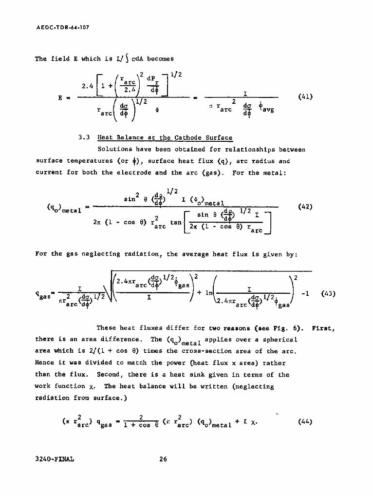
The field E which is I/~ cdA becomes
El 2 dP ]112 re rc r
2.4 + \ 2. / ' ) d-~ T (41)
E =' == do)I/2 2
r ~ .~ r da ~avg arc d-'~ arc d~
3.3 Heat Balance at the Cathode Surface
Solutions have been obtained for relationships between
surface temperatures (or 4), surface heat flux (q)~ arc radius and
current for both the electrode and the arc (gas). For the metal:
t/2 sin 2 e (~) I (~o)meta 1 = u ? ( 4 2 )
(q°)metal 2~ r 2 Fo sin 9 (~) 1/2 I ] (I - COS 6) tan[_=
arc ~ (i - cos S) tar c
For the gas neglecting radiation; the average heat flux is given by:
qgas" ~rarc~W~ __I 4~rarci~) I/2~gas~ + inI2
i !2 • 4-~ra rc (dd-~) 1/2 .~g a
-i (437
These heat fluxes differ for two reasons (see Fig. 6).
there is an area difference. The (qo)meta I applies over a spherical
area which is 2/(1 + cos 8) times the cross-section area of the arc.
Hence it was divided to match the power (heat flux x area) rather
than the flux. Second, there is a heat sink given in terms of the
work function X. The heat balance will be written (neglecting
radiation from surface.)
rarc) qgas = 2 (r. 2
I + cos e rarc) (qo)metal + I X-
First,
(447
3240-F~NAL 26

AEDC-TDR-64 -107
It is necessary to obtain information about ~gas" ~ in
the arc is related to the field E by:
I (45) = 2 do
rarc d~ E
Applying this relationship at the surface, ~gas can be eliminated~, in
terms of E s. The resulting heat balance was multiplied by (d~)I/2/l
and the result is:
2 .d.j.i/2 Es rarc - I 2:4 + In .4
d~)i/2 Es rarc
i~ \112
~) (~o)metal +
sin @ (d~)l/2 l
tan[ 2~ (l-cos ~) rat J
( d~ 112 W7 ×
(46)
In order to apply Eq. (46), (~o)meta I was taken to be
the melting value(it would not be necessary to do this if more information
were available) and the field in the gas near the surface was obtained
as follows: The electron current Je is written in terms of oE
[el2 ne 3 2~ kT E (47)
Je = kT T m Z n. qi e i i
The electron current can also be written in terms of the charge and
mean velocity :
Je " ne [el ¼~8~kTm (48) e
3240-FINAL 27

AE DC-TDR-64-107
Eliminating Je we get:
8 kT ~. z- lel ni qei (49)
i
The sum of products of number density and cross-section is over
values for gas atoms and ions of electrode material. The number
densities are related to the partial pressures, and the total pressure
is equal to the pressure at the outside plus the average magnetic pinch
pre | sure.
kTEniq i - (nak T) qea + (nI kT) qel (50)
u Pa qea + PI qel
No 12
Pa + Pe + P~ " Pa + 2Pz = Po + 8 2 r 2
arc
Combining the above, we get:
(51)
Po 8 + 2 qea + Pl qe ' (52)
ES " 3~ lel o 8 2 rarc
where qea has been neglected compared to qel" qea and qel are given
in terms of the temperature. PI can be found since it is the vapor
pressure of the electrode material. Eq. (52) can be used to eliminate
E s from Eq. (46). This equation now has two unknowns, I and rat c
(Po and Temp are considered known). I and rarc are related by
j . I + cos e I__/____ (53) 2 2 '
~r a rc
where j is a function of T (from the Richardson equation or a plot
of thermlonic emission). See Figs. 9 and I0.
5240-FINAL 28

A EDC-TDR.64-107
[I ~ I01° I ° ° [ I I I I I
II~.', .,ooT~ ~o.,o ,o-,~ . ~ _ , o 9
~'~ lO-' ~ " , ~... lO 6 El=
VAPOR PRESSURE'~ %N DENSITY ~ :::) W AND Th W ---,,, a. I0 "~ 10 7
0,. '~-BOI LING POINT ~ 0
10-4 _ ~ lOS %
\ \
lo-Si J I I I I 1.6 1.8 2.0 2.2 2.4 2.6 2.8 3.0
TEMPERATURE, ~.~.1. x RECIPROCAL I 0 +4 ) - 1 %
I~ 10 5
FIG. 9 VAPOR PRESSURE AND THERMIONIC EMISSION CURRENT DENSITY FOR TUNGSTEN (Determined from Data of Ref. 5)
3240-Final 29
7369968

AEDC.TDR-64-107
,o °
I0 -I
i10-2
a. I0 -3
D.
10-4
10-5
\\ VAPOR PRESSURE \\
\ \
41~ BOILING POINT ~
3.2 3.6 4,0 4.4 4,8 5.2 5.6 6.0 R E C I P R O C A L T E M P E R A T U R E , (,,.1_: x 10 +4) -R
10 5
10 4
iO s o~E
IO 2
C~
I01
,o °
FIG. I0 VAPOR PRESSURE AND THERMIONIC EMISSION CURRENT DENSITY FOR COPPER (Determined from Data of Ref. 5)
3240-Final 30
369979

AEDC-T DR.64-107
The problem then has a solution, which is a value for
E and etc. for each value of F and surface tem- I, rarc, s Pcathode' ' o
perature. Figs. ii and 12 show typical solutions.
3.4 Heat Balance at the Anode Surface
The problem for the anode is very similar to that of
a cathode. The principal difference is that the work function is a
negative number. Alsoj it is the anode material atoms (not ions)
which are present in the arc, and hence in Formula 52, replace qel
by (qea)anode material"
3240-FINAL 31

iolO 4-- o
!
m
N
~- 10 9 - ID
ID
¢%
E
i--- 1 0 8 -
Z i , i
I--
Z ILl D~ IIC
U I 0 7 -
IO G -
,o'
v
& hl
,o'
=, ,o' m
I.L
0
I-- 0 W . J W
-- ' ' ' ' " " 1 ' ' " ' " ' " 1 ' ' ' ' " " "1 ' ' ' ' " ' : , - TUNGSTEN -
m
m
m
m
m
D
m
m
,o" ~ , , , / , , I I I I l l l l l l , I0 ° I0 10 2
I , (Total Current )
I I I I I 1 1 1 1
I 0 3
~ . . ~ i0 -4 I
m
I I I I I I 10-5
10 4
i 0 o l _
IO-Z
l0 -3 d -
a
n,-
10 5
10 4
In
o
EL
i.i
10 3 ~; 0 EL ILl Q 0 n,- I-- 0 W .J
10 2 W
IO
m
&
O
FIG. ii THEORETICAL SOLUTIONS FOR TUNGSTEN CATHODE

L~
C ) !
=-=j i-=,
i - -=
L~
io lO .--
O,I I 0 9 -
, I , - ,
Q .
E <~
I - 1 0 8 -
Z
W a
I-- Z ILl
U 10 7 -
iO s. _
IO8 I
~E
LLI
I.i.
( J n~ I-" ( J ILl _1 IJJ
m
1 0 7 m
,o' F
1o" I 0 o
1 , I I , , , I I I I I IJ l I I i I I ' l l l l I i
T . O . , A T E O T U . O S T E .
I 0 10 2 10 3
I , (To Io l Cur ren t )
I 1 1 I I I -
/ -
IO - i
1 0 - 2
v
=o -3
O
r r
0 n~
10 . 4
1 0 - 5
10 4
_ i o 4
- - IO 3
O
(3.
LO
- - 1 0 2 0 ~ (3_
W a O n," I-- L.) LI,J _ I
I ILl - - IO
_ IO 0
m c3 c)
;o & i J O ",4
F I G . 12 THEORETICAL SOLUTIONS FOR THORIATED TUNGSTEN CATHODE

AEDC-TDR-64-107
4. CATHODE SPOT EXPERIMENT
The theory for the attachment of arcs in high pressure gases to
metal electrodes as developed in Section 3 predicts some
quantities which can be measured. The power absorbed by the electrode
is the one quantity that can be measured with accuracy and compared to
the predicted values. Most other measurable quantities, e.g., arc spot
size and surface temperature, involve either elaborate equipment to
make the measurement or some rather broad assumptions in order to
interpret the measurement. Accordingly, an experiment was set up to
measure the power lost to an arc cathode under closely controlled
conditions. Since the pressure appears as a parameter in the theory,
the equipment was designed so that it could be operated at pressure
of from 1 mm Hg up to 2 atmosphere.
4.1 Test Geometry
The apparatus for experimental investigations of the cathode
attachment region required the solution of many design problems before
a satisfactory unit was constructed. These problems arose mainly from
the conflicting requirements of good visibility of the attachment region
and of confining the arc to foma a stable operating configuration. Use
of buffers and magnetic fields to stabilize the arc resulted in obscura-
tion of the attachment zone and other operating problems. Deletion of
these components for improved visibility resulted in the formation of
coatings on the transparent chamber wall and unstable operation under
some circumstances. The final configuration chosen was a bare cathode
in which the arc was stabilized by the injection of high velocity gas
very close to the cathode tip. This configuration is shown schematically
in Fig. 13. Photographs of the test geometry assembly and its compon-
ents are shown in Figs. 14, 15 and 16. While this unit gave
satisfactory performance for the most part, coating of the chamber
walls persisted and interfered with pyrometer and spectroscope
measurements.
The principles of operation of this device are similar to
conventional arc heaters. Gas enters a plenum in a phenolic housing
3240-FINAL 34

0~
o o
t o I,O
O I
~zJ I - ' -
m t_i
t o t n
MOUNTING FLANGE
COOLING WATER
I N - ~ OUT
IN -~D,:
O U T ~
TUNGSTEN CATHODE TIP
WATER COOLED SHROUD
ANODE
T ,--~ ANODE
COOLING WATER
COIL
BORON NITRIDE INSULATOR
THROTTLE
GAS INLET
GAS INJECTION ORIFICES
COIL
t ~ ~ , , l ~ ANODE COOLING
PYREX CHAMBER
FIG. 13 SCHEMATIC DRAWING OF CATHODE TEST APPARATUS
111 O
:4
;O & |
O

AE D C - T D R - 6 4 - 1 0 7
~.,;..;.~. ,-:~-:-.
• -~ ,,'/;-: ~.
Q
FIG. 14 EARLY ARC CATHODE ASSEMBLY
3240-Final 36

A E DC-TDR-64-107
" I 2' - -
FIG. 15 COMPONENTS FOR ARC CATHODE STUDY
3240-Final 37

A EDC.TDR-64-107
FIG. 16 ASSEMBLED EQUIPMENT FOR CATHODE STUDY
3240-Final 38

AEDC-TDR-64-107
that contains the cathode assembly. Orifices in a boron nitride
insulator-positioning block provide passages for the gas from the
plenum to the cathode tip. The velocity vector at the point of
injection forms a 45 ° angle with the plane of the axisj providing high
velocity 3 vortex flow over the tip. Cooling water for the cathode tip
and cathode housing are provided at the mounting flange. The coolant
flows~ in addition to maintaining wall temperatures at reasonable
values~ provide a means for determining the heat loss to the cathode.
The arc is struck from the cathode to an annular anode
which is also water cooled. An axial magnetic field produced by the
coils interacts with the arc current to provide a rotation of the anode
attachment point reducing the local heat flux. Finally a throttle is
provided to control the chamber pressure and flow rate. The heated
gas is exhausted to a vacuum system. Fig. 17 shows the cathode and
column operating in a stable mode with argon as the heated gas.
4.2 Instrumentation
The instrumentation used in these tests is surmnarized in
Table I. These measuring techniques have been evolved and previously
used at EOS for accurate determinations of the performance of arc jet
propulsion devices. A complete discussion of these and other arc jet
measurement techniques is given in Ref. 3.
4.3 Experimental Results
Fig. 18 shows some results of the above experiment for argon.
The power in the cathode cooling system is plotted versus the current~
and the results are compared with the theory. Also shown on the same
flgure are additional data for a similar configuration in a hydrogen
arc jet. ~npublished EOS Data).
3240-FINAL 39

A E DC-T DR-64-107
FIG. 17 CATHODE ATTACHMENT AND COLUMN DURING OPERATION
3240-Final 40

c) I '-d
i .e.
i . .=
¢.. i--=
2.4
2 . 0 t
Jl¢
0.~ 1.6
w" C3 0 "1-
1.2 <[ U Z
n," 0.8 IJ.J
0 O.
0.4
I ' I ' I ' I ' I ' I ' I
0 ARGON HYDROGEN
o
EXPERIMENTAL
® ®
®
® ® ®
THEORETICAL
®
®
®
t
O I J
o 200 400 600 800 I000 1200 1400 CURRENT, I (omps)
FIG. 18 COMPARISON OF MEASURED AND THEORETICAL VALUES FOR CATHODE POWER
1600 18OO
> 111 K~
N :4 K~ ;U
&
O

4> O !
H Measurement
I. Cathode Voltage
TABLE
Instrument ~anufacturer~
Voltmeter (Rowan) Oscilloscope
Z
0 - 500 v
Accuracy (Calibration Method)
112%
m
O
h
& |
o
2. Cathode Current Ammeter (Rowan) Oscilloscope
0 - I000 a ± 112%
3. Gas Flow Sonic Orifice and Helix Gage Transducer
Unlimited I - 2~ (Collection in Meteoro- logical Balloon)
bJ
4. Coolant Flow
. Coolant Temperature - Differential
ASME Orifice with Hg Manometer, Rotameters
Copper-Constantan t.c.'s in Differential Electrical Circuits. Laboratory Potentiometer (L & N)
Unlimited
na
1/2% (Direct Weighing)
l/2% (Mfg. Guarantee)
6. Visual Record of Cathode Spot
High Speed Motion Picture (Fastax - WF3)
8000 fps max.
n a
7. Chamber P r e s s u r e Bourdon Type Gage (Wal lace 0-50 mm and Tierman)
1747.
8. Discharge Spectra Spectrograph f 6.3 (Jarrel-Ash)
9. Total Radiation Optical Pyrometer I%

AEDC-TDR-64-107
5. RETROGRADE MOTION OF THE CATHODE SPOT
When the work described in this report was initiated, it was felt
that a study of the retrograde motion might help in understanding some
of the basic mechanisms occurring in the cathode attachment region. The
investigations carried out in the previous sections slowly led us to the
conclusion that this was not true and that the retrograde effect
basically resulted from effects outside the attachment region.
However, a few of the analytic results obtained during the time
that we studied the retrograde effect will be presented and the
experimental equipment built to measure some critical phenomena
predicted by us to be present when motion occurs will be described.
5.1 Analysis of Retrograde Effect
From the outset, we adopted the hypothesis that retrograde
motion results from forces on the volume of the ionized gas in the
discharge and is not a surface effect. Starting from this, it is
possible to use equations for the amhipolar motion of the charged
particles through a partially ionized gas and solve in general terms
for the velocity of these particles in a discharge when electric and
magnetic fields are applied.
The general equation for ambipolar diffusion in a partially
ionized gas is given in Ref. 2 and is reproduced below with a few
changes of notation.
J x B (J x B) x B
IBl 2
,, n i l e I IBI
+ (%~e~/~ I) (
F1 ) (54) (1 + pl ) IB[
(F 1 - F2) X B l 2
J
3240-FINAL 43

A E D C - T D R - 6 4 - 1 0 7
where :
n
-~= kT ea
qea fez (2) qel lea (2)
n Z + n a qea fez (2)
(2) qeI lea
(55)
"= kT Dla
n n a
(n a + ni)2 (56)
F I = E + v x B + ]-~ (Vln Pe + Ke Vln T)
f- kT | Pe PZ
F2 " T~in Pa ÷ (K e - KI) Vln T~
n (2) a qea fe~. ='= (2) 131 ~ qle lea
(57)
(s8)
(59)
J = charge particle flux
Equation (54) can now be changed into a form where the J x B and
(J x B) x B terms are replaced by terms including the electric and
magnetic fields. After some algebra 3 the following expression is
obtained:
3240-FINAL 44

A EDC-TDR-64-107
M+ -(L I +
I+P i
• B B
R T ~ " ( q " B) B
m
[BI 2
(60)
whe re
M = ~- -~ -~ - - [ e l ' "J- cvl ~I nl(Fl " F2) I + Pl [el n z v IB[
W T e e
(6Z)
I
h " [e l , = I F I - l e [ '=Z (F1 " v ~ B) (62)
2 c I
(z + % % =I ~'I) 2 + (% "e )2
I + tD T e e wI ~ -
(63)
(64)
Q,fw e
+ e
", % ~z le[ nz ('{ - F2) +
r e [e I n I v IB[ + i + "i
l e [ n I F~
i+13 L
l+w T e e WT TT~
2 (% T)
(63)
3240-FINAL 45

AEDC-TDR-64-107
In order to obtain a relation connecting the various components of the
ion velocity that is valid in an electric discharge with a transverse
magnetic field it is convenient to make two simplifying assumptions as
follows:
17 The components of v, F~, and F 2 in the direction of the
applied magnetic field can be neglected.
2) (~llt + ~i ) (l/~,e-e) << i, and
The relation shown below can now be obtained from Eq. (65) if a
configuration is picked in which the electric discharge is along the
y axis and the applied magnetic field is in the z direction.
2 (~e Ve ) w£ vl
" 2 + Ux l + (w e re) + we Ve wI vl
+
2
l+ (%2 re) (F{-iB[F2)y+ ®i iv + We TeF'tY2-Ftx' (% r e) (% Ve 7 [BI
(667
where U = absolute velocity of ions and electrons moving together, i.e.,
charged particle motion which carries zero electric current. Because
of this definition, the x-component of U represents the absolute
velocity of the cathode spot.
If the only gas velocity present is Vx, that due to the electro-
magnetic forces, then U is the diffusion velocity of the ions in the Y
+ y-direction due to the applied electric field. The arc should
then move in the + x-direction since all of the terms on the right
and become side of Eq. (66) are positive. However, if WeT e ~7 I
quite large, e.g., low ambient pressure and a fairly strong magnetic
field, then Uy can be the dominant term on the right side of Eq. (66).
3240-FINAL 46

A EDC-TDR-64-107
If some mechanism is now present to drive the ions against the
electric field in the y-direction, then the direction of U will reverse X
and the cathode spot will move in the retrograde direction. A likely
mechanism to cause the ions to move against the applied electric field
is that of the cathode jet. When the cathode attachment region of the
arc covers a very small area, then the discharge expands and accelerates
the gas away from the surface. For reasonable expansion area ratios the
ions can be forced to move against the field and thus initiate the
retrograde motion of the arc column near the cathode. The various
physical processes necessary to retrograde motion are discussed
below:
i) The ions are accelerated away from the cathode spot and
move against the electric field. The electromagnetic force on the ions
is now in the retrograde direction. In a configuration with no forced
gas flow, this ion motion is accomplished by the electromagnetic pumping
force in the expanding arc column of the discharge as one moves away fr~n
the cathode attachment spot.
2) The arc current plus an added current to compensate for the
ion motion is all carried by the electrons.
3) The total collision cross-section of the electrons with
neutral atoms must be very much greater than the total collision cross-
section for the electrons and ions. Because of this the net body force
~ j x B d V is transferred to the neutral 3 non-luminous gas which is
put into motion in the proper j x B direction.
4) The net force on the ions is now the resultant of the
following 2 forces:
a) Electromagnetic body force in retrograde direction.
b) Body force in proper direction due to collision with
electrons and atoms.
When (a) is greater than (b)~ the ions will move in the retrograde direction.
Due to the negligible inertia of the electrons, the ion motion determines
the motion of the arc column. Hence the criterion for retrograde motion
of the cathode spot is that the electromagnetic forces on the ions. be
greater than the collision forces on the~ whEn.the ions move against the
applied electric field. 47
3240-FINAL

AEDC-TDR-64-107
5.2 Retrograde Motion Experiment
Investigation of the retrograde motion phenomenon in an arc
required a high level of sophistication in the design of apparatus and
instrumentation. Large values of rotational velocityj small electro-
magnetic interaction forces, small internal clearancesj and the
requirement for annular cathode and anode geometries are among the
problems that must be considered~ many of which are more severe than
"conventional" arc jet design problems.
The equipment built for these experiments had the potential to
enable accurate controlj measurementsj and observation of the retrograde
motion. Howeverj many practical difficulties were encountered which
limited the amount of useful data obtained.
Some of the more important design criteria which were incor-
porated into the initial geometry were:
I) Provision was made to measure the total momentum transferred
to the gas due to the electromagnetic forces on the gas.
This would be accomplished by measuring the torque on a
plate with fins that stop the rotational component of
gas velocity.
2) The magnetic field was tailored to be uniform over the
region of the discharge so that the electromagnetic
interaction force on the gas was just ~ B l~ where I is
the total current, B is the applied magnetic field 3 and
I is the length of the discharge. Provision was made
to vary the magnetic field B from ij000 to over 10~000
gauss, the current I from I ampere to over I00 amperes 2
and the electrode separation I from about 2 mm to over
I0 mm.
3) A comparison of the measured momentum change of the gas
and the electromagnetic body force~ which would give
some indication of the momentum lost by viscous drag
effects on the gas flow over the electrodes~ was
provided for.
3240-FTNAL 48

AEDC-TDR-64-107
4) The inner and outer rings that confine the discharge were
electrically insulated from each other so that the potential
difference parallel to the applied magnetic field developed
in the discharge could be measured. This measurement
would be very important in helping to determine the total
electric field strength in the cathode attachment region.
The resulting device is shown schematically in Fig. 19 and in fabrication
in Figs. 20 and 21. The apparatus as shown in Fig. 19 consists essentially
of toroidal electrodes 6 inches in diameter. A magnetic field is focused
by high-permeability iron in a radial direction between the electrodes
such that an arc struck between the electrodes in a direction parallel to
the axis of the electrodes will be perpendicular to the direction of the
magnetic field. The cross-section of the cathode torus is conical so that
the surface of the cathode to which the arc attaches is a circular line.
The thin edge of the cathode was fabricated from thoriated tungsten rod
formed in a circle and brazed to a copper ring. The cathode is located
between two buffer rings which form an annular gas inlet noxzle at the
arc attachment region of the cathode. The anode is a water cooled copper
ring with a flat surface in the region of arc attachment. After the gas
passes from the annular nozzle into the arc region~ it must then pass
through radial holes in the torque-sensing stator before discharging
into the vacuum system. This stator is in close proximity to the anode
and buffer rings but is suspended only at the torque sensor and does
not make contact at any other region. The stator directs the gas in a
radial direction such that the J x B forces added to the gas in the arc
chamber are ultimately applied to the stator and measured by the torque
sensor. After leaving the stator~ the gas enters a large volume stilling
space between the stator and the housing and then passes through an
annular space between the throttle plate and the stator. The flow
through the throttle plate is normally sonic; thus~ the annular area can
be selected to establish the internal operating pressure. Also~ it was
possible to bleed gas into the space upstream of the throttle plate to
control the internal pressure.
3240-FINAL 49

L~
0
i ~ .
~n 0
VIEWING WINDOW
STATOR GAS PASSAGES
VIEWING WINDOW
GAS IN LE'I'
INSULATOR
ANODE - COOLING
WATER BRASS ISTATOR COOLING
~' STATOR | WATER
h TORQUE SENSOR ST~AJN. , r (ST ST )
THROTTLE
: x i,. **
...................................................
~:~:~:~$~:~:~:~:~:~:~:~:~:~:~:~:~:~:~:~:~:~:~:i: :::::::::::::::::::::::::::::::::::::::::::::::::::::: :+:.:.:.:.:+:.:.:.:.:-:+:.:.:+:.:.:.:.:.>:.:.:.:.:.:.:.:.:.:.:+:+:+:-:+:.:. :::::+:+:':+:':':'::::+::': +:'::
~ : ~ : ~ : ~ : ~ , ~ % : : : : ' ! : : . •:+:•:•:•:•:•:•:•:•:•:•:•:•:•:•:•:•:•:•:•:•:•:•:•:•:•:•:•:+:•:•:•:•:•:•:•:•:•:•:•:•:•:•:
"~ BUFFER CATHODE ~ , COOLING COOLING ~ GAS INLET l J WATER I_MAGNETIC
WATER FIELD COILS %
A X I A L
DUCT
ANODE
"OPPE R BUFFER
TUNGSTEN RING
_BUFFER COOLING WATER
MAGNETIC CORE I RON
111
N
(31
&
o ",,4
FIG. 19 RETROGRADE MOTION EXPERIMENTAL APPARATUS

FIG.
AEDC-TDR-64-107
20
FIG. 21
RETROGRADE MOTION APPARATUS MAGNETIC CIRCUIT COMPONENTS (Disassembled)
RETROGRADE MOTION APPARATUS MAGNETIC CIRCUIT COMPONENTS (Assembled)
3240-Final 51

A EDC.T DR-64- I07
The initial series of tests were conducted with the assembly
mounted in a vacuum chamber. Argon was fed into the chamber and the gas
pressure was maintained between 0.5 and 15 nln. An arc was initiated
between the electrodes and rotated rapidly around the ring in the J x B
direction. However 2 it was not possible to sustain the discharge at
current levels below 50 amperes~ possibly because of the characteristics
of the power supplies~ and hence a great deal of gas heating occurred.
The residual ionization level of this heated gas appeared to be high
enough so that numerous attachment points appeared on the electrodes.
This made it impossible to measure a rotation rate with the photocells.
The pressure in the chamber was changed over quite a wide range
(0.5 to 15 mm) in an effort to try and obtain a single attachment
point on each electrode. This appeared to have no noticeable effect~
other than causing a change in the frequency of the noise heard coming
from the equipment.
As a result of the problems encountered during this test seriesj
the equipment was modified to enable control of lower current levels
(~ I amp) and to inject gas over the cathode tip in an attempt to
stabilize a single cathode attachment point.
In the second test series~ three techniques for measuring
the rotation rate of the cathode spot were installed in the retrograde
experiment. The photocells were used again~ but this time they were
mounted six inches away from the cathode~ so that noise from the arc
and the magnet coils was reduced. Effort was also made to electrically
shield the leads completely. As a second way to measure the rotation
rate~ a small pick-up coil was mounted in the cathode to measure the.
flux change as the current density passed through it during the rotation
cycle. This technique proved very reliable during experiments at the
California Institute of Technology in measuring arc rotation rates.
Thirdly# high speed photography (52000 - 7j000 frames/sec.) was used to
try and get the rotation rate. This technique had previously been
successfully used by Mr. Eric Soehngen at ARL.
The modifications to the retrograde equipment over that used
previously are shown in Fig. 22. Essentially~ the cathode was buffered
3240-FINAL 52

0 I
- - 0 . 4 o , ,OJ~
r11
q~ ;u
& 4b,
O
FIG. 2 2 MAGNETIC CIRCUIT RETROGRADE MOTION APPARATUS - PHASE I

AEDC-TDR-64-107
in an attempt to force discharge attachment to the ridge. Provision was
also made to flow gas over the cathode through the buffering rings.
After the retrograde equipment was fitted with buffer
electrodes to confine the flow over the cathode ring~ the apparatus was
mounted in the vacuum chamber and connected for testing. A current
of from I to I0 amps was passed through the discharge. The current in
the magnet circuit was varied over a range of 0 to I~000 amps. During
all of the tests it was found that the current would jump intermittently
to the buffers from the cathode and then to the anode. This made it
impossible to measure the rotation rate of the cathode spot. The arc was
observed to rotate in a rather discontinuous manner. Injecting gas
between the cathode and the buffers appeared to have a significant effect
on the rotation rate. However 3 because of the shorting to the buffer~ no
quantitative data could be obtained.
The equipment was then modified by adding some insulators for the
buffer so that arcing to the buffers should not occur. Insulation was
placed over all exposed portions of the buffers and electrodes except
for the anode face and the cathode edge. This was done in an effort to
prevent secondary discharges or shorting to the buffers. Numerous attempts
werd'made to initiate the arc and measure its rotation rate. In all of
these attempts the discharge burned through the insulation and attached
at a point 3 rather than rotating around the cathode ring. Upon making a
detailed examination of the configuration it was discovered that the
anode had been separated from the cathode by an added 0. i0" in order to
mount the insulation. This made a 0.20" gap between the cathode and
anode~ which possibly accounted for the difficulty in obtaining a proper
rotating discharge.
The gap was then reduced to 0.040" and the retrograde equipment
was run several times. In no case was it found possible to stabilize
the arc and obtain a significant rotation rate. The discharge was
observed to move in the retrograde direction as the ambient pressure
and magnetic field strength were varied. However~ no consistent or
reproducible rotation rates were recorded. Upon examination of the.
3 240-FINAL 54

A EDC-TDR*64-107
equipment, it was found that the cathode and buffer rings had shorted
together so that the discharge occurred between the buffer and the
anode.
Although time consuming, the various operational problems
incurred in the apparatus during this program were characteristic of the
type of small practical problems arising when a new design concept is
used. Although many features of the design can be improved upon, the
essential design criteria are met in the device. Therefore, a future
investigation should probably modify the existing apparatus where
necessary rather than attempting a completely new approach.
3240-FINAL 55

AEDC-TDR-64 -107
6. CONCLUSIONS
I. A sct of mechanisms have been postulated to describe the
phenomena occurring at the cathodes of high current, high pressure
arcs. Using these mechanisms, an analysis of the mass and energy
transfer characteristics of the cathode attachment zone has been
carried out and closed form solutions obtained in terms of known
physical constants.
2. The predicted value of power loss to the cathode, as
determined by theory, is compared to the measured values of cathode
power absorption and the correlation appears to be reasonably satis-
factory.
3. The theory predicts a rather strong dependence of the cathode
behavior upon the pressure of the ambient gas. The details of this
dependence have not yet been thoroughly investigated.
4. The theory introduces the electrode configuration into the
predicted performance capability of the cathode. This should even-
tually let us optimize the cathode shape for any desired performance.
5. A critical condition for the arc attachment to a cathode of
conical configuration has been found. An unconfined arc will not
attach to the cone tip when the ambient pressure is lower than some
critical value. A diffuse attachment to the siae of the cone occurs
at the lower pressures. The "critical" pressure at which this
phenomena occurs appears to be approximately the same, independent of
whether the gas pressure is increased or decreased through the critical
value.
6. A self-consistent explanation for the phenomenon known as
"retrograde motion" is postulated. Preliminary expressions are
derived for the retrograde velocity of the cathode spot in terms of
the magnetic field strength, gas propertiesj and the velocity of the
gas in the direction of the applied electric field.
3240-FINAL 56

A E DC-T DR-64.107
7. RE CO~MEN~DAT IONS
i. Spectroscopic ~neasurements should be made of the cathode
attach;,:ent zone to atter:pt to oetect all species present there. In
particular, efforts should be maae to determine whether or not atoms
and ions of cathode material exist away from the surface. If they are
found, then the distance that they extend away from the surface should
be determined.
2. Measurements should be made of the power loss, material loss
rate; and area of arc attachment on cathode surfaces of various
configurations over a wide range of arc current and ambient gas
pressure.
3. The phenomenon of a "critical" pressure (noted in Section
6.5 of Conclusions) for the arc attachment to a conical cathode tip
should be investigated experimentally, in detail.
4. The analysis of the cathode attachment region should be
extended to include the effects of the radiation from the gas to
the cathode surface and of the radiation from the cathode.
5. The analysis should next be modified so that it can predict
the loss rate of cathode material.
6. The energy equation for the electrons should be evaluated so
that non-equilibrium electron temperature effects can be introduced
into the various cathode mechanisms.
7. The analysis should be applied to the anode attachment zone
of high current, high pressure discharges.
57

AE DC-TD R-64.107
REFERENCES
i.
.
.
.
.
.
.
.
Ecker, G., "Electrode Components of the Arc Discharge", Ergeb. exakt. Naturwiss 33, 1-104 (1961)
Cann, Teem, Buhler and Bronson, "Magnetogasdynamic Accelerator Techniques", AEDC-TDR-62-145 (1962)
Cann, G.L., et al "Thermal Arc Jet Research", Aeronautical Systems Division, Technical Documentary Report No. ASD-TDR- 63-632, Classified Confidential (Title Unclassifed)j Electro- Optical Systems, Inc., (15 August 1963)
Handbook of Thermophysical Properties of Solid Materials. The Macmillan Co. (1961) (Sponsored by WADD)
Handbook of Chemistry and Physics. Chemical Rubber Publishing Co. (1947)
Lee; T. H., "T-F TheQry of Electron Emission in High-Current Arcs", J. Appl. Phys. 30, 166 (1959).
Bade, William, et al, 'Theoretical and Experimental Investigation of Arc Plasma Generation Technology" Aeronautical Systems Division, Technical Documentary Report No. ASD-TDR-62-729, Part II, Vol. I, AVCO Corporation, September 1963.
Neuroth, P. W. and Gibbs, T. W., "Arc Cathode Emission Mechanisms at High Currents and Pressures", J. Appl. Phys. 34, 277 (1913).
3240-FINAL 58