UNCLASSIFIED AD NUMBER - DTIC · No types of fabrication, vacuum forming and welding; were useJ....
30
UNCLASSIFIED AD NUMBER AD853872 NEW LIMITATION CHANGE TO Approved for public release, distribution unlimited FROM Distribution authorized to U.S. Gov't. agencies and their contractors; Critical Technology; MAY 1969. Other requests shall be referred to Naval Training Device Center, Attn: Code 424, Orlando, FL 32813. AUTHORITY usntdc ltr, 9 Dec 1971 THIS PAGE IS UNCLASSIFIED
Transcript of UNCLASSIFIED AD NUMBER - DTIC · No types of fabrication, vacuum forming and welding; were useJ....

UNCLASSIFIED
AD NUMBER
AD853872
NEW LIMITATION CHANGE
TOApproved for public release, distributionunlimited
FROMDistribution authorized to U.S. Gov't.agencies and their contractors; CriticalTechnology; MAY 1969. Other requests shallbe referred to Naval Training DeviceCenter, Attn: Code 424, Orlando, FL 32813.
AUTHORITY
usntdc ltr, 9 Dec 1971
THIS PAGE IS UNCLASSIFIED

-ft
-Technical Report: NAVTRADEVCEN 66--C-0077-1
THREE-DIMENSIONAL TARGETS FOR THE POP-UP DEVICES
M31AI AND 3C52
Fiial Design and Evaluation Report
-i)i-i.Aip Brie;f
John A. Raffo
RAI Research CorporationLong Island City, New YorkContract N61339-66-C-0077
May 1969
DoD Distribution StatementThis document is subject to special export
controls and each transmittal to foreigngovernments or foreign nationals may bemade only with prior approval of theCommanding Officer, Naval TrainingDe•vce Center (Code 4?4), Orlando,Florida 32813'.
NAVAL TRAINING DEVICE CENTER
"ORLANDO, FLORIDA

NAVTRADEWVCEN 66-GC-0077-
ABSTRACT
The development of targets filling a volume of space equal to thatof a soldier in the kneeling firing position is described. The targetswere designed for use with a pop-up target holder, device M3lA1 and
S~3C52 using a vibration sensitive hit switch. Three forms of targets,l each of linear polyethylene, are described. When viewed from the
front, all targets presented the silhouette of the planar kneeling targetwhich ic currently being used. The target depth (8 inches) was
developed by a projecting sheet welded to a planar board in the case ofthe T" type target. A formed Aggressor target was vacuum formedto an 8-in, depth with features similar to an aggressor soldier.trdypofagedvepdwsa l-oudihdph Aeeoe
by a half cylinder section in the body and a trapezoid cross-sectionin the head.
High response accuracy was obtained with the Aggressor form andthe Hiall-Round target. The "T" type could not be fabricated in a formsuitable for the purpose. Response accuracy above 98% was obtainedwith Half-Round and .Aggressor" targets, but difficulties wiih the target.
i ~holding device prevented the assignment of a particular accuracy figurea• characteristic of the targets. Realism can be obtained with the
i ~targets described by using decais, coating, and by use of colored,E plastic.
Field evaluation at training sites is recomnmended for the Half-
SRound adAggressor fomdtargets.
S, • • •Reproduction of this publication in! f"/•'•!t _ ! t ~ whole a puror p• in part o°teis Untdpermitted Sttsfor
! I , Government.

NAVTRADIEVCEN 66-C-0077-11
FORE WORD
A continuous problem exists to develop a realistic, economic Pnddurable target for the training of combat zcroops. The expanding fleldof plastic applications has made it possible to up-grade many standardlow cost target systen'a. Cardboard targets, though reasoniable, have ashort useful life and have environmental limitations. In &n. #earlier atudyunder Contract N61339-1820 different materials were exarmned in aneffort to up-grade the silhouette targets an~d backboards for mountingopen cell polyurethane foam 3-dimensional targets. Polyethylene targetreplacements proved to be a significant advancement a~s they toleratedextreme weather conditions and have a 'life expectancy five times greaterthan that of cardboard. The present study shows that polyethy-enes areeasily formed into the configurtation of a man from the front as 'Well asthe side view. The effectiveness of the various molded target configu-rations is presented in this report. Additional efforts are scheduledon the new material targets, particularly field evaluation- tests atTraining Center Firing Ranges. The results of field evaluations willprovide a basis f br r-insiering the 4 'argeta for U. S. Armyv and U. S,Marine Corps standardiza-zion.
DAVID T. LONG~
Proiect EngineerNav8l Training Device Center

SV NAVTRADEVCEN 66-C-0077-1
TABLE OF CONTENTS
Sectionag
INTRODUCTION ....................... 1
"STATEMENT OF THE PROBLEM ........................... 3
ME1THOD OF PROCEDURE.... * * . ... . .... . .00 4
DISCUSSION. *.... ................. ...... .... ... . ,. 6-- •"T" Type Tagt6
Thrme-Dimensional Aggressor Target.......... 8Half-Round Target..........,.,....... .17
CONCLUSION AND RECOMMENDATIONS.................... .23
LIST OF ILLUSTRATIONSn i~ur• ag
1 "T" Type Target..,. .... .. ....... ,.,......,..090 . 7
2 Aggressor Target. ... . o .......... o0#000006 9
3 Half-Round Target... 18
LIST OF TABLES
Table Pae
1 RESPONSE ACCURACY RECORD OF .093-IN. THICKAGGRESSOR TARGET (INITIAL DESIGN). ........... Ii
2 RESPONSE ACCURACY OF .075-IN. THICK AGGRESSORTARGET (SECOND DESIGN) ..... .... .... . .......... L.
3 RESPONSE ACCURACY OF AGGRESSOR-FORMED TARGET•-(FINAL DESIGN) ... oo.......ooooo15
4 RESPONSE ACCURACY OF AGGRESSOR-FORMED TARGET_ (FINAL DESIGN)... o........... .. ........ o. .... o..o..16
5 RESPONSE ACCURACY OF TWO HALF-ROUND TARGETSý,i°••INITIAL DESIGN). .... o...... o............. ... .... 9
6 RESPONSE ACCURACY OF HALF-ROUND TARGET( FINAL DESIGN) ....... 20
itl

NAv7RADEVCEN 66-C-0077-1
SINTRODUCTION
The pop-up type target has been accepted as astandard training device in training military personnelto fire a rifle effectively. Originally, this typedevice was operated by a timing mechanism which returnedthe target to a horizontal, non-visible position after
S* a certain time period. The scoring of hits was thendetermined by a visual count of holes in the target.A later type device, the 3C52 mechanism, contains aprovision for automatically lowering the target whena target hit was scored. The operation of this deviceis triggered by a vibration sensitive microswitchmounted on the target-holding clamfp; when a bullet hitsthe target ohe switch is actuated by the vibration ofthe target.
With the introduction of the 3C52 device, a needarose for an improved target. The response of the earlytargets was found to be adversely affected after havingbeen subjected to high humidity or rainfall. A program,Army Project No. I-P-0-13001-A-039, conducted byRock Island Arsenal's laboratory, resulted in thespecification of the current fiberboard target. Thesetargets are now being procured and are required to provide24 kill responses for 25 hits by 30 caliber bullets. Inactual use it is found that the response accuracy isapproximately 80% after 400 rounds. (See Test andEvaluation Report, Contract N61339-1820, 29 Aug. 66.)
During a target material development contract,N61339-1820, linear polyethylene targets which providedresponse accurecies as high as 98.9% for a 960 hit firingtest were evaluated. The purpose of the project, on whichthis report is written, was to develop targets suitable for trainingexercises, utilizing the M31A1 device in flanking fire situations.
The project was initiated to develop a three-dimensional target which would occupy the volume of aman's torso and could be mounted on the M31AI and 3C52.Such a target should be suitable for use in tacticalfield exercises.
The final test of any target used with the pop-updevice is its ability to actuate the device when hit bya bullet. The M31Al and 3C52 rely uponi a vibration orshock actuated device to sense the bullet striking thetarget. There is no known means of measuring the

SNAIVTDEVCEN 66-C-O077-1
ability of a target to perform in th' pop-up deviceby a laboratory type test. Therefore, each targetdesign must be subjected to range testing.
2
_.;_I

NAVTRADEVCEN 66-C-0077-2
STATEMU1 OF THE PROBLEM
The targets developed during this eontract wereto have a frontal silhouette identical- to the kneelingtarget as shown in Rock $slli Arsenal drawingNo. 8426438. The weight of the developed target shouldnot exceed 2.75 lbs. which is the maxilnum weight theM31Al and 3C52 pop-'up devices can lift. The responseacu-uracy of tLe target should at leabt meet the existingspecification for the fiberboard kIeelin? target. Thenew targets should be three-dlinensicnai with a profiledepth of 8 in. or 9 in.
The target would be required to fit into thecurrent dev•.ce , Snd tfunctoin with no alterstiorof the devt,•e,,
mT
I
*1

xNAVTPADtVCEN 66-C-0077-1
METHOD 0P PROCEDURE
There were certain conceptr, which influenced thedesign of the target. These piding concepts were baseiupon observations which had been made during ContractNo. K'51339-1820. Flexible draterials or structures hadpoor issponse while rigid structures had 1zairovedresponze. It *as assumed that a material o;, rtructurewhich required the bullet to transmit a greater part ofits envi-ffg before passing through would be capable ofafforN!ng a target of superior performance. Forms hadto flex as units; those containing sections which mil;flex independent of the remainder were avoided.Similar~l>, axes about which a part of the target couldbend were avoided.
No types of fabrication, vacuum forming and welding;were useJ. The design of a target for vacuum forningwas followed by production of a mold to be used for partforming. In all instances male molds were used. Moldswere nmade from wood, wood covered by epoxy and fromHydrocal plaster. These types of molds were used becausethe number of parts to be made per mold was limited.
In practice, forming the parts was found difficultwhen using these molds. The heat of the heavy (.090 in.)plastic sheet used in constructing the target, dried thewood and caused shrinkage and slight mold deformity duringthe forming of the first few parts. Once the eiivinkagehad begun, mold seams and Joints opened and parts formedsubsequently adhered to the mold. invariably destroyingthe mold when the part was removed. The Hydrocal moldswere affected in a similar way. In this case, where amold vas made from several pourings into a cavity, theJoints of the successive layers were weak spots and hada tendency to crack when heated by vacuum-forming.
The range tVsting of targets was accomiplished atthe Naval Training Device Center. Targets were mountedin a M31Al and 3C52 and fired at from a dis-ance of25 to 50 rds using 30 caliber Spitzer pointed bulletsin au M-1 Rifle. The target-to-rifle-angle was varieddu.-ng the test to include aiming at the frontalsilhouette, a side view of the target and an Intermediate
angle. Patterns were fired at local areas of the targetto determine if any target areas could be distinguishedby performance.
Unfortunately, there were no means by which thepe:rformance of the device, independent of the target,could be established. In fact, it was necessary to
4I

NAVTDRADVCEN 66-C-0077-1
assume that the device was in good working order and thisassumption was always based upon the performance of thetarget. When targets were performing poorly the devicewould be overhauled and a change made in the vibrationsensitive microswitches.
The device in use pe:,formed well during the fir'strange tests. After this time the prototype targetsbeing used ranged from poor to excellent in performance.Thepp d'fferences in target performance suggested thatthe deviue was operating well. Later in the program theperformance of all targetc, including '.hose t•,at had beenexcellent daring previous tests, became fair or poor.STle device was overhauleO and new microswitches installed.The performance of all targets improved after this was
The vibration sensing microswitch, used in thepop-ap device, has contacts close in its rest state. Whnenvibration or shock is sensed by the switch, these contactsare opened. The manufecturer's quality control test ofthese switches is performed by mounting the switch on arevolving wheel and noting the r.p.m. at which the switchopens. Switches opening between 3-5 g's are rated asacceptable,
The microswitches utilized s1ould have been testedand numerically specified before ani s.Pter being used onthe range. Since this was not done, thle uest tias lfssprecise than otherwise would have beet. tie case,
-i1/)

NAVTRADEVCEN 66-C-ooT7-1
DISCUSSION
"T" Type Target. The "T" type target was constructedofa sheet of linear polyethylene, essentially identicalin form to the kneeling target, onto which an 8-in. widesheet of plastic was welded to the centerline of thebackboard and making a right angle with backboard plane.This 8-in. projection terminated three to five inchesfrom the bottom edge of the target so as not to blockthe seating of the bottom edge of the backboard in thetarget clamp. A "T" type target is illustrated inFigure 1.
The initial target tested was f'bricated by cuttinga formed plastic kneeling target in half at the verticalcenterline. These two halves were joined to a sheet ofplastic inserted between them. The welded assembly thenpresented a "T" type target configuration. All elementswere of T075 in. to .080 in. linear polyethylene. Intesting this target on the firing range, the welded jointseparated. It was also noted that bullets striking theprojecting element of the target had a tendency t. key-hole through the backboard portion.
A second linear polyethylene "T" type target wasfabricated. This target was made by joining an 8-in.wide section of sheet to the length of the centerlineof a sheet of plastic with the silhouette of a kneelingtarget. Welding beads were applied on both sides ofthe weld joining the two sections.
The performance of this target and the first targetwas the same; the weld separated after several roundswere fired into the weld line.
A third "T" type target was then designed andfabricated with no welded joints. A single sheet ofplastic, approximately 40 in. x 36 in., was folded atthe centerline so that it appeared to be 18 in. x 40 in.Each 40 in. edge was then folded (one in a clockwisedirention and one counterclockwise) to provide a 9-3/4 i.i.width iormal to the original plane. This provided a "T"structure with a double thickness in the projecting part.To seat the target in 4he clamp it was necessary to cutit at the bottom edge, where the projection met the clamp.The target was fabricated from a sheet .063 in. thick andthe target weight wns 2.81 lbs.
When tested, this target had a tendencj to whip.Increasing the thickness of the sheet would result in an
6

ifI I"
FT:' Figure 1. "T" Type Tar-get
7

NAVTRADEVCEN 66-C-0077-1
excessively heavy target. Additionally, the "T" typetarget was conceived as a target which would carry a formelement to simulate the appearance of an aggressor soldier.This would increase the weight required by 1 lb. Forthese reasons this unit was not considered a satisfactorytarget element.
This configuration was abandoned at this point,since there did not appear to be a design or fabricationmethod that would lend itself to the development of asuitable "T" type target.
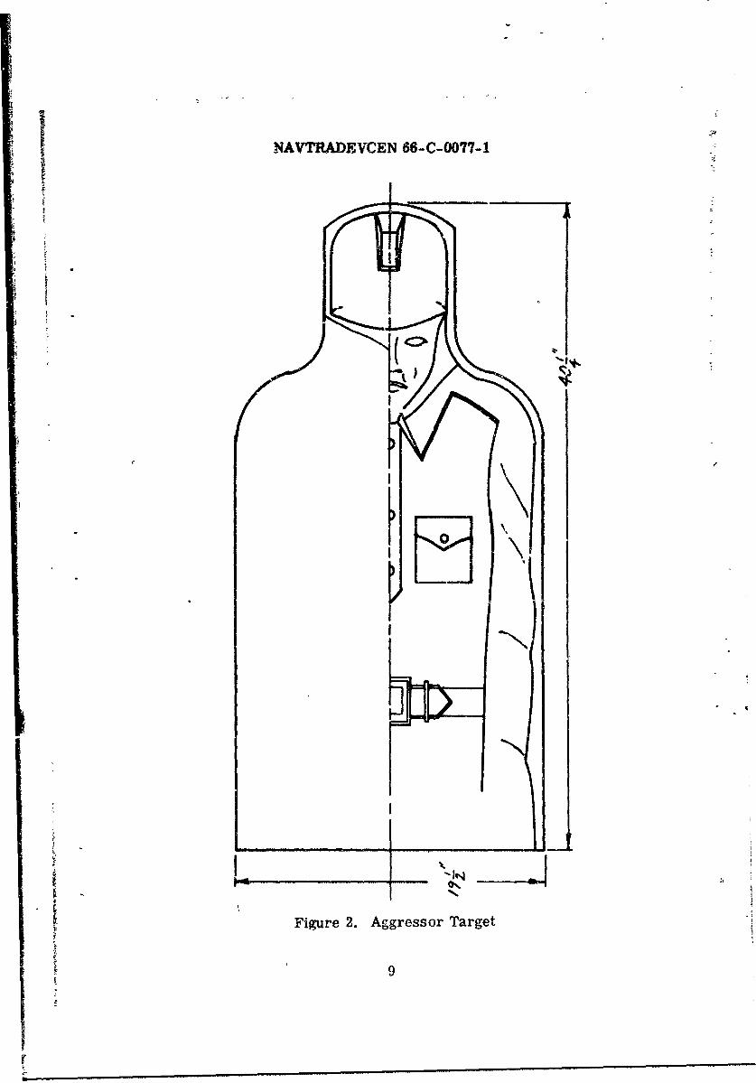
Three¶Dimensional Aggressor Target. The three-dimensionalaggressor target was to approximate the silhouette of thekneeling target as shown in Ordnance Drawing C8426438.The target was to provide a representation of the aggressorsoldier as depicted in FM30-101-Cl, 27 April 1962.Uniform details were taken from Figure 13 of this FieldManual, which illustrates the Senior Sergeant of aMechanized Rifle Division. The target was to be life sizeand limited to representing the torso of such a soldier.The depth of the target was to be 8-in. An aggressortarget is shown in Figure 2.
The target material was to be linear polyethyleneand the part was to be made by the vacuum forming overa male mold. The target was to be designed to allow fox,nesting in storage.
The initial mold made had a large part of the depthdeveloped by the draw of the sheet at the edge of theform. Thus, a draw of more than 6 in. occurred in awidth of less than 1-1/2 in. This draw resulted in avery thin edge. The edge sections thinned out to leasthan 50% of the initial sheet thickness. The target-holding clamp grips the bottom edge of the target for alength of approximately 14 in. The length of the bottomedge of the target is 28 in. Therefore, a large part ofthe target did not receive stiffeni•ng from the clamp.
Testing a 75-mil target on the firing range indicatedthat response accuracy was poor. The target had aresponse accuracey of 78.7% for 300 test rounds.
When the target was examined in the device clamp, itwas apparent that the sides of the target were able toflex or vibrate independently of the mass of the target.It was first thought that i"Ais probably was responsibl.!for the poor target performance. This effect, howeve:,was due to the thin gauge of the drawn plastic at the
0
IB
NAVTRADEVCEN 66-C-0077-1
I N\
5;
Figure 2. Aggressor Target
9
r

MAWAvTMnICEN 66-0-n077-1
sides (outside arm sleeves), the fact that this surfacehad prartically no formed surfaces (was flat), and thesmall size of the target holding clamp in relation tothe target. The response accuracy of a .093 in.aggressor target of this type is detailed in Table 1.
At this point in the program it was not known if
a target of the configurations proposed could performsatisfactorily in the existing clamp. This was in doubtprimarily because of the small length of the targetclamp relative to the length of the bottom edge of thetarget.
To as.oertain if the performance of the target wouldbe improved by providing additional rigidity to the form,modification of the target described above was undertaken.
A target formed on the same mold and of the samegauge sheet was cut so that a 3/4-in. flange extendedaround all the edges of the target, except the bottomedge. This was incorporated to increase the integralrigidity of the target. Additionally, two creases wereformed with hand held tools into each sleeve of theaggressor target. After these modifications the targetwas then tested on the range.
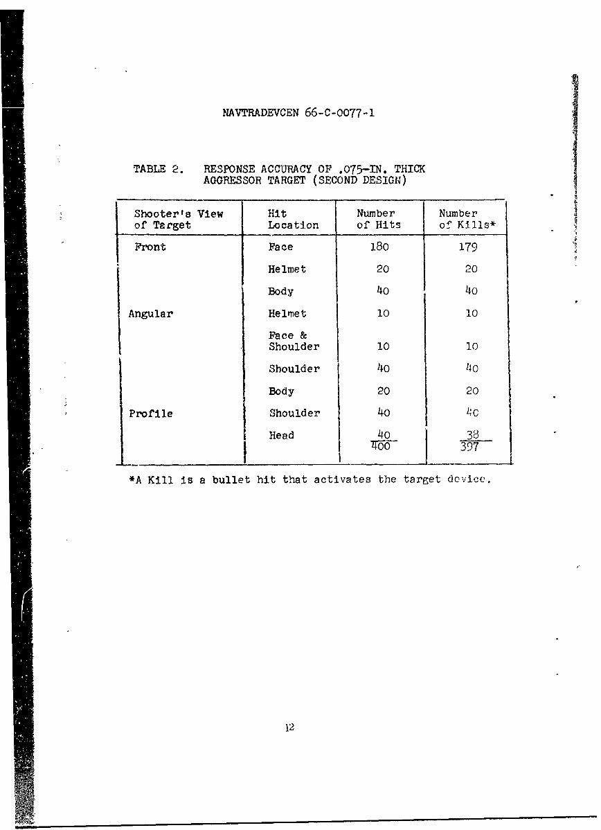
The range testing was conducted with 30 caliberSpitzer type pointed bullets. Rifle-to-target-distancewas approximately 25 yards. The target weight was 2.27 lbs.400 Rounds fired into the target resulted in 397 hitswhich activated the device and 3 hits which did notactivate it. The tabulated data for this test is presentedin Table 2.
This test demonstrated that the existing devicetarget clamp could be used to hold a flanking fire targetand allow for good hit response accuracy. Also, the testestablished the importance of forming creases at the sidesleeve surfaces of the target. These tests wereinterpreted as verification of the value of the flange inenhancing the performance of the target.
The changes in the targets which were undertaken atthis time involved the production of a new mold. Thismold was to provide for a flange of 1/2-in. around allperipheral edges except the bottom. Additionally, creaseswere placed in the sleeves to provide stiffnes for thesurfaces of the target. To reduce the drawing at thesidoes and edges of the target, which tended to provide athin gauge at these surfaces, the body of the target torso
10

NAVTRA-DECEN 66-C-0077-1
TABLE 1. RESPONSE ACCURACY RECORD OF .093-IN. THICKAGGRESSOR TARGET (INITIAL DESIGN)
Shooter's View Hit Number Numberof Target Location of hits of Kills*
Front 20 20
Edge 20 19
Body 20 20
Face 100 86
Profile 60 55
Angular 60o
*A Kill is a bullet hit that activatts the target device.
zi
iI
NAVTRADEVCEN 66-C-0077-1
TABLE 2. RESPONSE ACCURACY OF .075-IN. THICKAGGRESSOR TARGET (SECOND DESIGN)
Shooter's View Hit Number Numberof Target Location of Hits of Kills*
Front Face 180 179
Helmet 20 20
Body 40 40
Angular Helmet 10 10
Face &Shoulder 10 10
Shoulder 40 110
Body 20 20
Profile Shoulder 40 4C
Head 40 38400- 397
*A Kill is a bullet hit that activates the target device.
12
MNAYTRAM CEN 66-C-0077.-1
was rounded somewhat so that the draw was reduced at theedges.
The average weight of the twelve 90--ril agressortargets before coating was 1160,3 grams or 2,;blbs. Themaximum target weight was 1190 grams and the minimumweight 1137 grams. The targets delivered during thiscontract were formed from natlral color polyethylene.To afford realism to the targeta they were coated with avinyl green and skintone paint. To improve adhesion, thetargets were wiped down with solvent to remove any releaseagent or surface contaminant. A rubber cement was thenapplied to the surface of the target. The vinyl paint wasapplied over the dried rubber cement.
In practice, the coating did not perform satisfactori-ly. The paint tended to fracture in the area where abullet penetrated the target.
In producing a target formed to represert anaggressor soldier, the target should be made from plasticthat is extruded with the color of the aggressor uniform.The skin color can be obtained by applying a heavycoating of an organosol colored to skin tone. The weightof this coating over the face area would not be excessive•,whereas a coating over the entire target would beexcessive in weight.
The range testing accuracy of this target was doubtfuldue to the condition of the pop-up target holding mecha-nism. Ilor example, the delivered end item tested out asgiving a 90.4% hit accuracy for 260 rounds. Subsequently,the M31A1 and 3C52 device was overhauled and the sametarget had 95.5% accuracy for 210 test round ' cs. Thisvariance is too large to be within the limits of normaldeviation.
Similarly, an identical aggressor target elementwithout paint coating on initial testing gave 340 hitresponses for 340 target hits. When the device becamesuspect, this target had 92.1% response accuracy for560 test rounds. This data illustrates the lack ofprecision in the range test.
Daring the tests reported or, the direction of fireat the target was varied and firing was accomplished atspecified target areas to determine if the response ofany area was poor relative to other areas. The areasof approximately h.kree or four inches dia,,mter belof theshouider top on either side of the head, consistently
13
NAVTRADEVCEN 66-C-0077-I
gave response averages below that obtained for the restof the target. No explanation for this difference isavailable. The rigidity of the suspect surface wasexcellent and it did not appear that a shock to thissurface could be localized. There was no basis forGistinguishing between the suspect surface and other3urfaces of the target except for that noted in rangetesting.
Data obtained in testing two targets of the finaldesign are given in Tables 3 and 4.
!4
-414

NAVTRADEVCEi; 66-C-0077-1
|A.-ATABLE 3. RESPONSE ACCURACY DF AGGRESSOR-FOMKED TARGET
(FINAL DESIGN)
Shooter's View Number of Number of
of Target Hits Kills
a * assorted 340 340b side 80 70c opposite side 180 175d 80 77e side 40 37f angular 180 157g angular 100 97h front 100 96i angular 100 94j side 100 96k angular 100 951 opposite angular 80 76
M side 60 60
. Response Summation Hits Kills Percent
*I a) 340 340 100b)-f 560 516 92_.1g)- M) 64o 614 95.9
*Data are listed in time sequence in which it wav obtained.Data listed on lines d, e and f was obtained on the sameday. Data from lines g - m were obtr;ined after devicewas overhauled.
15
f -

NAVT RADEVCEN 66-C-0077-1
TABLE 4. RESPONSE ACCURACY OF AGGR E S SOR-FOMFD TARGET 1(FINAL DESIGN)
Shooter's View Number of' Nzmber of
of Target Hits Kills
a)* angular 20 15b front 20 18c angular opposite 80 76d angular 60 53e profile 80 73
angular 80 77opposite angular 140o 128
Respo nse Summation Hits Kills Percent
aj - di 180 162 90.0e) g 300 278 92.7
J
*Data listed on lines e - g were obtained after thedevice was overhauled.
16

X1 kDECEN 66-C-07-1
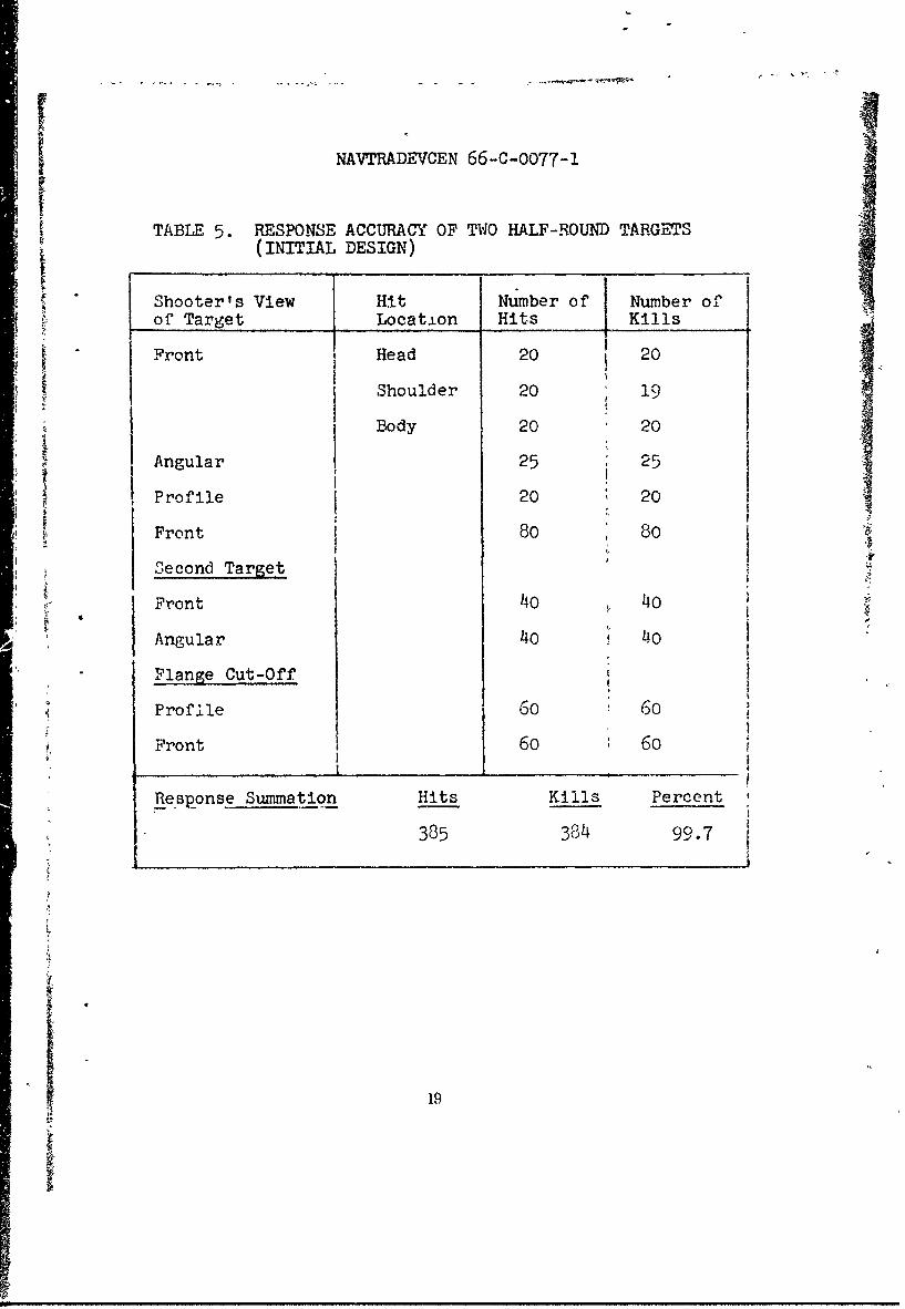
Half-Round Ta. . This target was designed to have anSin. depth. The depth was developed as part of acylinder of 9-1/16 in. radius. The surface of the cylinderutilized had a chord of 18 in. and a height Of 8 in. Thebody of the target conformed to the cylinder section. Thehead section was also 8 in. in depth, In cro=-sectionthe heed was a trapezoid of 7-1/4 in. base and 7/8 in.width ait the top. The height was 8 in. The target wasdesigned to nave a 3/4 in. wide flange along the bodyperimeter and a 5/8 in. wide flange at the perimeter ofthe head. This target is illustrated In Fig•ure 3.
S~This target, made from .090 in. thick plastics
functioned very well. (See data in Table 5.) Hoiver,due to the 9-1/16 in. radius of the body, it spreadout when inserted into the 15 in. radius of the M31Alarx] 3C52 target holding clamp. This effected a changein target dimension so that when viewed from the frontit had the eppearence of a trapezoid.
The ir•.itial range tesv' of a 90-mil target formedto the half-round configuration described above resultedin 365 hits with 364 device responses for a responseaccuracy of 99.7%.
Modification of this target was initiated toincorporate several changes in the target design. Firstly,it was deemed desirable to have the bottom edge of thetarget formed to the same radius as the target holdingclamp. Additionally, a reduction in flange width wasattempted. The original mold was modified to effectthese changes. However, when attempts were made to formthe part the mold was destroyed by heat of the plasticsheet. (The mold was of wood.) A new mold was made withHydrocal plaster and this was used to form the partsdesired. However, there was an error in mold design andthis resulted in a part that was not in conformity tothe kneeli.ng target silhouette.
n•Fnally, a mold was made to produce a target in theform of th,? original target but modified so that thebottom edge had a radius of 15 in. for a length of14-1/2 in. The results of limited testing of this finaltarget are given in Table 6.
A decal designed for this target is made of 5-railvinyl film mith an elastomer coating protected by paper__ n the back of the vinyl. To attach the decal to thetarget the osper is peeled off and vii,y) pressed onto thesurface of 4 ,'e target. The color scheme of an aggressorsoldier and the skin tone is obtained with vinyl colors.
• 17

NAIMADEVCEN 66-C-0077-1
+ +
SSEC,,TIOV "-A "
Figure 3. Half-Round Target
18
NAVTRADEVCEN 66-C-0077-1
TABLE 5. RESPONSE ACCURACY OF TWO HALF-ROUND TARGETS(INITIAL DESIGN)
Shooter's View Hit Number of Number ofoC Target Location Hits Kills
Front Head 20 20
I Shoulder 20 19Body 20 20
Angular 25 25
Profile 20 20
Front 80 80
econd Target
Front 40 40o
Angular 4o 40
Flange Cut-OffI
Profile 60 60
Front 60 60
Response Summation Hits Kills Percent
385 384 99.7
19
1 .. . . . . .. . . . . . . . . . . . . . .

NAVTRADEVCEN 66-C-0077-1
TABLE 6. RESPONSE ACCURACf OF HALF-ROUND TARGET(FINAL DESIGN)
Shooter's View Number of Number ofof Target Hits Kills
Angular 40 36
Front 80 78
Angular Opposite 40 39
Responsee Summation Hits Kills Percent160 15-" 95.6
____0
- 20

NAYTRADEvCEN 66-c-oo-r-i
RESULTS
The three target designs, mentioned under disucssion,"T"-type, aggressor formed target and half-round, wereevaluated.
The "T"-type target was eliminated due to the failureof welded Joints and the impossibility of obtairing highresponse accuracy with this target form in the e-istingclamp.
The aggressor form and half-round targets were bothcapable of delivering exceptionally high responseaccuracy. However, one pop-up device was used and whenthis device became suspect, all test targets performedpoorly. After repairs and overhaul of this device,performance improved but did not equal that originallyobtained.
As has been discussed earlier in this report, thesensitivity of the vibration-actuated microswitch, locatedon the M31Al and 3C52 device, is believed to be of primaryimportance to the results obtained on the firing range.The performance of the device can become suspect whenbullet hits on one side of a target do not result inkills as frequently as those on the opposite side.Occasionally, the response of a target will not be equalto the response previously obtained on the same target,and creates suspicion of the device. In such an instancethe only recourse has been to overhaul the device andreplace vibration sensitive microswitches with new ones.It is unfortunate that the microswitches used did nothave numerical test values which could be related tothe switch.
Difficulties of the type described above did makesome of the test results questionable. However, theability of a half-round and aggressor form target torecord approximately 350 hits accurately must be attri-buted to the target, since this type of performance couldnot be obtained with targets not suited to the device.
the Tests were conducted to determine if certain areas of
the targets were less respon3ive than others. Shoulderregions of the targets proved to be less responsive.This was particularly noticeable when the device was not functioningproperly. These regions are a part of the slope of the shoulder of the half-round target and a small surface on the front of the aggressor target in the
NAVTRADEVCEN 66-c-0077-1
shoulder region. No other target areas ceuld bedesignated as being less responsive than other areasof the target.
The target configurations produced during thecontract may have suffered slightly in range evaluationdue to the condition of the clamp. The clamp used was ashop fabricated version of the actual clamp. It wasmade of aluminum and was more flexible than the actualclamp would be. It was used in all the testing reportedhere, and though it was never suspected as being a factor,being different from the design part warrants mentioning.
22
22

NAVTRADEVCEN 66-C-0077-1
CONCLUSION AND RECOMMENDATIONS
The project reported on has demonstrated that theexisting pop-up target mechanism, without any modification,can be used with targets which occupy a volume of spaceequal to that of a man in the kneeling position whenfiring a rifle.
Two types of targets were found to be suited for? this purpose. One target, Aggressor, formed in the
figure of an aggressor soldier, and another, Half-Round,formed from geometric sections and n decal, depicts anenemy soldier by stylized coloring of the decal.
Both targets have been demonstrated to afford highresponse accuracy in the pop-up device. A third tar'get,"T" Type, constructed by welding a projection onto .-heform of a plastic kneeling silhouette target, was notsuitable due to poor response and bullet destruction ofthe weld.
Much of the work accomplished during the course ofthis project was dependent upon the testing of develop.-ment targets mounted in the pop-up device at the firingrange. As has been indicated, these tests are dependentupon the performance of the device and indications arethat this performance is not a constant factor.
To improve the test reliability, it is suggestedthat a set-up duplicating or resembling that which isnow being used by the manufacturer of the microswitchesbe imcorporated as a part of the test apparatus forrange testing targets in the pop-up device. Then, bymeasuring the force required to open the microswitchswitches before undertaking a range test, and measuringthis force after a range test, any changes in the switcheswould be detected.
The Aggressor and Half-Round targets have both beendemonstrated as being suitable for use with the M3lAland 3C52 pop-up device. It is recommended that they begiven field evaluations by training commanders toascertain their value as training aids.
The Aggressor target allows realism to be achievedwhen the target is formed from a forest green colorand the face of the target is coated to simulate a skintone. Realism can be obtained with the Half-Round targetby a technique similar to that suggested for the Aggressor
4 or by the use of a decal mounted on the t3rget.
23

NAVTPADEVCEN 66-C-0077-0
The advantages of having a target in the form of aman cannot be simply assessed. One major contributionthis provides is the training of personnel to fire uponlifelike targets, which is a requirement for effectivemilitary action. Training with a target with aninanimate appearance may teach a trainee to hi,; a targetbut not necessarily to hit a man.
U

UNCLASSIFIED
DOCUMZNT CONTROL DATA R & D,5ecutt cIs:e=fa ¢Iton of rtifl, body .1 ab. , cI nd m-d..- nI 0!zr -:f ? be sb r .tered whsr, the o- i;; ýr t 1. I... U Iliad'
ORrIGINA TING AC I'VT- (C.'• .Or .f h .uthoo I " RE4O0 T ZC %,1PTY CLASSIFICATIOU
RAI Research Corporation UNCLSSIFIED36-40 37th Street 2b GROUP
1' Ln CityP ).V. i1013 RE OrT TITLE
TIIREE-DIEhSIONAL TARGETS FOR THE PO)P-UP DEVICES M31Al bnd ',C52
4 DESCRIPTIVE NOTE.A(7)-p.of e• t'd t" .d Inclus,.' dates)
Final Design and Evaluation Report5 AU NHOlI(St (Flrat Ma, midCe Initial. lastf nme)
Philip Brieffjohn A. Raffo
6 REPORT DATE IlTTL10O 4U 1 ý1qF
M•ay 1969 240. CON TRACT OR GRANT NO ISO. ORIGINATOR'S REPORT NJMRERSI
•,61339-66-C-0077b. PROJECT NO NAVRADEqCEN 66-C-0077-
C. Task 7882-5P2B,D 2Z, OTHER REPORT N0151 (Any o..t nob*.,,= t.ha ay be a.aI•.•dWhi. report)
SIn DISTRIBUTION STATEMENT
This document is subject to soecial export controls and each transmittal toforeign governments or foreign nationals may be made only with prior approval of*rnanding Officer. Naval Training Device Center (code 424), Orlando, Florida 32813.
1 SUPPF.PEMýNTARY NOTES 12 SPONSORING MILITAflY ACTIVITY
Naval Training Device CenterOrlando, Florida
13 ABSTRACT
Efforts to develop z three-dimensional real!!tic target are de-cribed. Targetswere fabricated from polyethylene for use with vibration sensing pop-up targetdevices. The frontal silhouette was that of the kneeling target now in use. Thedepth of the figure was eight inches. Two target configurations which were foundto be suitable were tested during the contract. These targets were a half-roundof a soldier with rigular geometric sections suggesting head and body. A decalcovering the plastic target provided color and detail. The Aggressor Formedtarget was made to have facial details (eyes, nose, etc,) and uniform detail(pockets, sleeve creases, etc.) molded into the part. Roth of these target* werecapable of providing high response accuracy when mounted in the pop-up device.
A 'T" type target fabricated by welding or forming a plastic sheet into a"T' configuration was not found to be uaable.
a
'A


![Silicone Smooth-On, Inc. Vacuum Macungie, PA • USA · 2019. 7. 22. · Vacuum Connector [STANDARD] Low cost alternative vacuum connection fitting for installation into rigid mold](https://static.fdocuments.us/doc/165x107/5fbdc7d8a33d7b742f0d12b9/silicone-smooth-on-inc-vacuum-macungie-pa-a-usa-2019-7-22-vacuum-connector.jpg)