UNCLASSIFIED AD-405 -123K - DTIC
87
UNCLASSIFIED AD-405 -123K DEFENSE DOCUMENTATION CENTER FOR SCIENTIFIC AND TECHNICAL INFORMATION CAMERON STATION. ALEXANDRIA. VIRGINIA UNCLASSIFIED
Transcript of UNCLASSIFIED AD-405 -123K - DTIC

UNCLASSIFIED
AD-405 -123K
DEFENSE DOCUMENTATION CENTERFOR
SCIENTIFIC AND TECHNICAL INFORMATION
CAMERON STATION. ALEXANDRIA. VIRGINIA
UNCLASSIFIED
NOC•CR: en government or other drawings, speci-fications or other data are used fr ay purposeother than in connetion vith a definitely relatedgoverinnt pmoeunit opezation, the U. B.Goverzment thereby incurs no responsibility, nor anyobligation what soeverj and the fact that the Govern-ant w have formulatedp furnishJed, or in wn waysuppliedL the said drawings. specifications, or otherdata is not to be regarde by luplicatLon or other-vise as in any inamer licensing the holder or anyother person or corporation, or conveying any ri4tsor permission to nsmfacturse, use or sell anypatented invention that mky In an way be relatedthezeto.

SWCTDRAFSWC-TDR-63-6 63-6
STUDY OF THE COLLAPSE OF
SMALL SOIL- SURROUNDED TUBES
Interim ReportMarch 1963
TECHNICAL DOCUMENTARY REPORT NUMBER AFSWC-TDR-63-6
Resk-arch Directorateu-p AIR FORCE SPECIAL WEAPONS CENTERAir Force Systems Command
C%4Kirtland Air Force Base..New Mexico
Project No. 1080, Task No. 108001
This research has been funded by thela Defense Atomic Support Agency under WEB No. 13. 145
(Prepared under Contract AF 29(601)-4927 byUlrich Luscher, Massachusetts Institute ofTechnology, Department of Civil Engineering,Soils Research Laboratories, Cambridge,Massachusetts)
, If

HEADQUARTERSAIR FORCE SPECIAL WEAPONS CENTER
Air Force System. CommandKirtland Air Force Base
New Mexico
When Government drawings, specifications, or other data are used forany purpose other than in connection with a definitely related Governmentprocurement operation, the United States Government thereby incurs noresponsibility nor any obligation whatsoever; and the fact that the Governmentmay have formulated, furnished, or in any way supplied the said drawings,specifications, or other data, is not to be regarded by implication or other-wise as in any manner licensing the holder or any other person or corporation,or conveying any rights or permission to manufacture, use, or sell anypatented invention that may in any way be related thereto.
This report is made available for study upon the understanding that theGovernment's proprietary interests in and relating thereto shall not be im-paired. In case of apparent conflict between the Government's proprietaryinterests and those of others, notify the Staff Judge Advocate, Air ForceSystems Command, Andrews AF Base, Washington Z5, DC.
This report is published for the exchange and stimulation of ideas; it doesnot necessarily express the intent or policy of any higher headquarters.
Qualified requesters may obtain copies of this report from ASTIA.Orders will be expedited if placed through the librarian or other staff memberdesignated to request and receive documents from ASTIA.
JI

TDR-63-6
ABSTRACT
This report describes a program of experimental and theoretical work
on the problem of failure of structural tubes surrounded by a thin layer ofsoil loaded by uniform radial outside pressures. The properties and the
thickness of the soil layer were varied, and the failure pressure of the tube,as well as the deformations of the tube before and after failure, was observed.Theories based on idealized models of the soil-structure interaction were de-
veloped. The experimental results were then correlated with these theories
to determine which, if any, of the theories explained the behavior of the
samples.
In addition to this work, a new testing apparatus was designed and built,
in preparation for similar tests with the tube buried under a plane soilsurface.
PUBLICATION REVIEW
This report has been reviewed and is approved.
1:PRICK TJOHN J. DISHUCK
Col .1 USAF Colonel USAF*Director, Research Directorate DCS/Plans & Operations

TABLE OF CONTENTS
Page No.
I INTRODUCTION 1
II THEORETICAL WORK 3
1. Introduction 3
2, Limiting Equilibrium Condition of a Soil Ring 3
3. Elastic Behavior of a Soil Ring Around a 5Rigid Inclusion
4. Over-all Buckling of a Cylindrical Shell 8
5. Buckling of an Elastically Supported Ring 10
III EXPERIMENTS AND RESULTS 12
1, Review of Previous Work 12
2. Further Tests on Aluminum Foil Tubes 13
3. Further Tests on Sand-surrounded Tubes 14
4. Tests on Grout-surrounded Tubes 15
5. Tests on Grout-sand-surrounded Tubes 17
IV DISCUSSION AND CORRELATION OF DATA 22
1. Old "Arching Theory" 22
2. "Over-all Buckling" Theory 24
3. Buckling of an Elastically Supported Ring 25
4. Conclusions 29
liii

Page No.
V, PLANE STRAIN APPARATUS 31
1, Dimensions of Soil Mass 31
2, Loading Scheme 31
3. Consideiation. Relating to Sample Preparation 32
4. Special Features 32
S. Tube Supports 33
BIBL IOGRAPHY 34
LIST OF SYMBOLS 35
TABLES 37
FIGURES 45
APPENDIX A
Stresses Around a Rigid Circular Inclusion 65
APPENDIX B
Buckling of an Elastically Supported Ring 69
DISTRIBUTION 74
iv

LIST OF TABLES
Page No,
Table I Bare Tube Tests 37
II Sand-surrounded Tube Tests - Data 38
III Grout-surrounded Tube Tests - Data 39
IV Grout-sand-surrounded Tube Tests - Data 40
V Sand-surrounded Tube Tests - Correlation 41by "Arching Theory"
VI Sand-surrounded Tube Tests - Correlation 42by "Elastic Buckling" Theory
VII Grout-surrounded Tube Tests - Correlation 43
VIII Grout-sand-surrounded Tube Tests Correla- 44tion by "Elastic Buckling" Theory
v

LIST OF FIGURES
Page No.
Figure 1 Equilibrium of Soil Ring 45
2 Soil Around Rigid Inclusion - Problem 45
3 Soil Around Rigid Inclusion - Solutions 46
4 Over-all Buckling of Composite Sample 47
5 Mohr Diagram for Cohesive Soils 48
6 Buckling of Elastically Suppotted Ring 48
7 Buckling of Elastically Supported Ring - 49Results
8 Hollow Cylinder Tests on Sand SO
9 Failure Phenomena of Sand-surrounded Tubes 51
10 Properties of AN-9 Grout 52
11 Triaxial Test on Grout-sand 53
12 Hollow Cylinder Tests on Grout-sand 54
13 Deformations of Grout-sand-surrounded Tubes 55
14 Sand-surrounded Tubes - Correlation by 56"Elastic Buckling" Theory
15 Correlation of Mode Numbers 57
16 Drawings of Plane Strain Apparatus (5 pages) 58
17 Photos of Plane Strain Apparatus 63
vt
INTRODUCTION
This Interim Report describes the progress of thesmall-scale soil-structure interaction studies conductedunder Contract AF 29(601)-4927 at the Massachusetts Instituteof Technology between 15 November 1961 and 15 November 1962.This research is a continuation of the small-scale soil-structure interaction studies undertaken at M.I.T. underContract AF 29(601)-1947 under sponsorship of the Air ForceSpecial Weapons Center. That previous work, "PreliminaryDesign Study for a Dynamic Soil Testing Laboratory," is de-scribed in Report AFSWC TR-61-58, Appendices K and L (Ref.(1)), and in "Basic Experiment into Soil-Structure Inter-action 0" by R. V. Whitman and U. Luscher, ASCE Journal ofthe Soil Mechanics and Foundation Division, December 1962(Ref. (2)).
The work done during this reporting period can bedivided into four major phases, and the report is organizedaccordingly. These phases are:
(i) Theoretical work. A number of soil be-havior and soil-structure interaction theorieswere developed in an effort to explain and cor-relate the experimental results.
(ii) Experimental work. This includes bothsupporting tests and interaction tests, Among thesupporting tests were soil properties tests, testson bare structural tubes, and tests on hollow soilcylinders without interior supporting structuraltubes. In the interaction tests, structural tubessurrounded by a layer of soil were subjected toincreasing outside radial pressures. The totalvolume changes undergone by the assembly duringthe test, the failure pressure, and the failuremode were observed. With the samples supportedin such a way that they experienced no axial strains,the soil was in a plane strain condition. Threetypes of "soils" were used. The soil propertiesand the thickness of the soil surrounding werevaried.
(iii) Correlation. The analytical theoriesand the experimental results were correlated todetermine whether the data fit one or more of thetheories.
-I-

(iv) Design of new equipment. On June 1i9621 the original contract was extended and widenedin scope to include investigation of tubes buriedunder a horizontal soil surface and subjected tovarying ratios of horizontal to vertical pressures.The only work done so far on this phase was con-cerned with the provision of the necessary equip-ment; the plane strain testing apparatus designedand built for these new tests is described in thelast chapter of this report.
As far as phases (i) to (iii) are concerned, itshould be understood that the sequence of the work was notas described here, but that experimental work, developmentof theoretical approaches and correlation attempts went handin hand, each contributing to the progress of the others.
As of the date of this report, the experimentaland correlation work of phases (ii) and (iii) was stillcontinuing. Thus the corresponding parts of the report :illbe very much in the form of a progress report on researchstill underway. The theoretical work of phase (i), relat-ing to the behavior of axially symmetrical soil-structureconfigurations, has essentially been completed, unless itshould become apparent that new theories are required toexplain the observed phenomena.
The research described in this report was performedin the Soils Research Laboratories of the Department of CivilEngineering at M.I.T. The head of the sdils laboratories isDr. T, We Lambe, Professor of Civil Engineering. The projectis under the direct supervision of Dr. R. V. Whitman, AssociateProfessor of Civil Engineering. The author is Instructor ofCivil Engineering.
-2-

II THEORETICAL WORK
1. Introduction
This chapter presents a number of theoretical deri-vations that have been employed in the analysis of the experi-mental results.
The basic problem, which is treated by variousmathematical approximations, is that of the interaction be-tween a very thin metal tube and a surrounding layer of soilof uniform thickness, acted upon by a uniform outside pressure.The ends of the tube are supported, and the length of thesample is maintained constant. Thus, if end effects arenegligible at mid-length of the sample, a plane strain con-dition exists there.
The metal tube used in the tests is a two-ply extra-heavy aluminum foil tube of 0.003-inch total thickness anda radius of 0.812 inch. In the earlier work (Ref. (1) and(2)) 10-inch long tubes were studied and were found to buckle,when there was no surrounding soil layer at 0.27 psi outsidepressure, but to sustain up to 10 psi outside pressure whensurrounded by a 3/8-inch layer of Ottawa sand. This sametwo-ply aluminum foil tube, and soil thicknesses of 3/16 inchand 3/8 inch, will be used in the following theoretical workwhenever numerical examples are given.
2. Limiting Equilibrium Condition of a Soil Ring
The limiting equilibrium condition for active arch-ing (compression failure) of a cohesionless soil ring wasderived in Ref. (1), Appendix K. Starting out with thegeneral equilibrium equation for stresses in a soil ring(Fig. 1), for axial symmetry of the ring and the loading,*
r * 9. -9 a 0(1)a'r
TAll symBols are defined where they first appear, and addition-
ally in the "LIST OF SYMBOLS."
"-3-
4
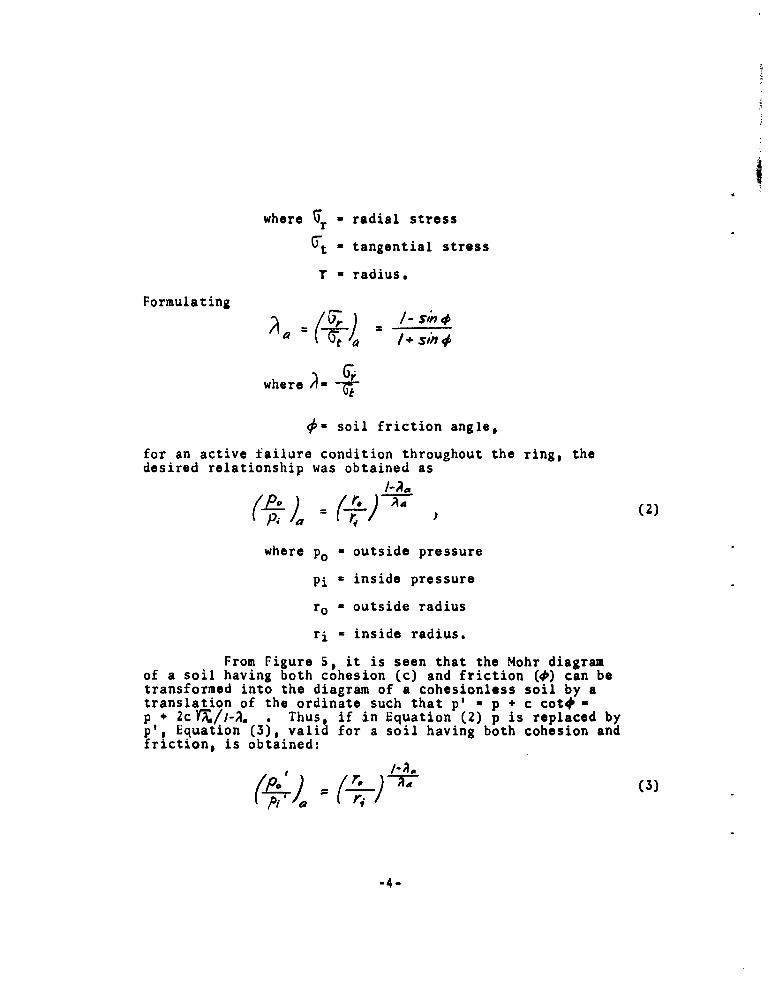
where r * radial stressr
yt - tangential stress
T - radius.
Formulating
where Gi
@= soil friction angle,
for an active failure condition throughout the ring, thedesired relationship was obtained as
S(2)
where po - outside pressure
Pi - inside pressure
ro - outside radius
ri - inside radius.
From Figure 5, it is seen that the Mohr diagramof a soil having both cohesion (c) and friction (0) can betransformed into the diagram of a cohesionless soil by atranslation of the ordinate such that p' a p + c cot# -p + 2cY•/I-A. . Thus, if in Equation (2) p is replaced byp', Equation (3), valid for a soil having both cohesion andfriction, is obtained:
-4-

with po' Po p 2c
P I a p1 + 2c
/ * sin #6
Equation (3) is not valid for a purely cohesivesoil 0 - 0) and must be replaced by
r,P0 " Pi 1ZC log (-F*. (4)
Equation (2), strictly speaking, is not limitedto an active arching condition, but holds for any ratioA - / which is constant throughout the ring. Thus, the
equation could be applied for "tensile" failure of the soilring by formulating
which, when substituted into Equation (2) leads to
which is Kirkpatrick's formula (Ref. (3)).
3. Elastic Behavior of a Soil Ring Around a RigidInclusion
As an approximation of the behavior of the soilaround an unyielding structural tube, the "elastic" behaviorof a soil ring around a rigid inclusion has been investigated.
".5-

For specific simple cases of assumed soil behavior,Equation (2) can be used to establish the relationship be-tween outside and inside pressures. The following caseswith a constant Yt/• ratio might be of interest:
Hydrostatic case:
"Zero tangential stress": -j- 0, since(Tt . 0.
"At rest": J'$ * l-sin# , since K o- (1-sin 0 ) r where Ko - coefficient
of lateral soil pressure at rest - l-sinO
"Tensile" failure: x--- i, $/n
Numerical answers for these cases have been calculated forro/ri - 1.46 and 0 - 370, and are presented in Figure 3a.
If the radial and therefore the tangential strainsof the tube are small compared to the strain required tomobilize any appreciable tangential soil stresses, a Kocondition (that is, with 1t as the lateral pressure at rest)immediately next to the tube is a reasonable assumption.This 1o-stress condition, however, would exist only in theimmediate vicinity of the tube, and would be modified fartheraway. This can easily be visualized for.the case of a rigidcircular inclusion in a uniformly stressed plane, in whichthe stresses would approach their undisturbed values at adistance from the inclusion. Thus the above at-rest solu-tion assuming constant Ot/~r throughout the ring is a roughapproximation only, which becomes progressively inaccuratefor increasing ring thickness.
A plane-strain solution for the case of an infinite-ly rigid circular inclusion in an elastic plane equallystressed in all directions has been worked out and is pre-sented in Appendix A. Figure 2 illustrates the problem andgives the notation. To summarize briefly the results, thedifferential equation for the inward radial displacement u is
1 _ d d2 a 0= 0 (6)
dr dr
-6

The solution for the boundary.conditions u (ri) = 0 andu (ro--01 O0) U0, is
a.r 90 -v-2z (7)
where -o - equal stress in all directions
of the plane
Es - modulus of elasticity of soil
V - Poisson's ratio of soil,
and the resulting stresses are
r / ( r2 (8)
> 97/-(V)(/- 2v )
2V (in axial direction).
The stresses are plotted in Figure 3b for V 0.4, V - 0.3and V= U.286. The last value is of interest because ityields an "at rest" condition with qt/Gr - 0.4 = Ko next tothe inclusion. Using v - 0.286 and a soil ring with ro/ri- 1.46, the ratio of Pi/Po becomes 1.19, as compared to 1.26
f r the approximate solution assuming a constant ratio oft/Gr equal to 0.4 throughout the ring.
A correction was made for the case of an assumeddisplacement of the tube (based on experimental data) of ui- 0.0005 inch by substituting this value as boundary conditioninto the solution of the differential equation. For Et400 ITo and ro/ri - 1.46, this resulted in Pi/Po . 1.11.
Thus, an exact solution has been obtained for thecase of an infinitely rigid circular inclusion in a uniform-ly stressed plane. The radial and tangential stresses varyat an appreciable rate with distance from the inclusion,
-7-

and therefozethe approximate solution assuming a constantstress ratio is valid only for very thin soil rings. Fromthe exact solution, ratios of inside to outside pressuresfor soil rings around unyielding cylinders can be obtained.Moreover, a small inward displacement of the cylinder canbe approximately considered and, as expected, somewhat re-duces the stress concentration around the inclusion.
4. Over-all Buckling of a Cylindrical Shell
The formula for buckling of a simply supportedcylindrical shell under radial outside pressure is given inTimoshenko (Ref. (4)) as
h n2 ~2 + h' ,3f2'• ),(92 12r1(H ,"), ) 9)
where Pcr - critical buckling pressure
E - modulus of elasticity of tubematerial
n - number of modes
h - thickness of tube
L - length of tube.
For a long tube, this reduces to the simple formula
PVh " (nz-I/) (10)Pc•y = (10)I-=)
E / 2r 3 (10)For thin soil rings of low modulus of elasticity
surrounding a structural tube, over-all buckling of the samplemay be the controlling mode of failure. To check this, theformula for buckling of a shell with a non-homogeneous crosssection has to be found. It is seen that the first term ofEquation (9) is proportional to the shell thickness h, thesecond term proportional to the moment of inertia I. By in-ference, therefore, the buckling formula for a non-homogeneouscross section might be written as
"-8-

where h' - equivalent tube thickness '--
V' - equivalent moment of inertia
r' - radius to center of gravityof section
j (subscript) - concerning the jth layer.
In this formulation, no bond stress is assumed toact between the individual layers; however, this assumptionhas to be verified in each case. The v in the last numeratorhas very little influence for n over 2 and may be given anaverage value.
Using as specific example the two-ply aluminumfoil tube of 0.003-inch total thickness, surrounded by soilwith a modulus of elasticity below 40 psi and with a maxi-mum thickness of 0.375 inch, it follows that h' % h and r''ral. Thus the presence of the soil is felt only in theinertia term.
Curves of Pcr/Eal (Eal - E of aluminum) versusn were calculated and plotted for soil thicknesses hs (aroundthe aluminum foil tube) of 0.188 inch and 0.375 inch, andmoduli of elasticity of soil Es of 6.7, 15 and 30 psi. Theminima of the curves yielded (Pcr/Eal)min and ncr (the criti-cal mode number), whereby it was stipulated that ncr neednot be an integer, but is that value leading to (pcr/Eal)min.The results are presented in Figure 4a, where (Pcr min-isplotted versus Es for the two soil thicknesses, and inFigure 4b, where (Pcr/Eal)min is plotted versus IV. Thislast plot is only possible because the first term of Equa-tion (11) is independent of the soil surrounding.
-9-

B
5. Buckling of an Elastically Supported Ring
In connection with the failure of a flexible tubesurrounded by a layer of soil, it appears pertinent to con-sider the problem of buckling of a ring subjected to largecompressive forces and elastically supported against deforma-tion (i.e., with counteracting radial forces proportional tothe radial deformation). This problem is analogous to thebuckling of a laterally supported column.
The mathematical approach to this problem is simi-lar to a derivation in Hetenyi (Ref. (6)), pp. 156-159 ex-cept that here the equilibrium equations must be formulatednot for the original, but for the deformed geometry, to allowfor an instability condition. The problem is presented inFigure 6, and the detailed derivations are reproduced inAppendix B.
The resulting differential equation for the ringdeformation is
ddsy (2,a) -~y #(krai)3 0, (12)
where y - ring deflection (outward positive)
0-= central angle
a = r 3 /EI , with r, E and I beingproperties of the ring
k = coefficient of elastic soilreaction
- average pressure applied on thering.
Formulating a periodic buckled form as y - B sin ny, thefollowing equation results:
n S_ n (2+ §)+ n (kra /) =+ (13)
-10-

U!
This equation was solved for • in terms of n, was minimizedwith respect to n, and yielded the approximate solution
2" k, (14)
which is valid for all practical values of k. Similarly,an expression for ncr was obtained as
n, = rF7 (15)
For the two-ply aluminum foil tube as structuralmember, these relationships are presented in Figure 7. whichis a plot of the critical tube buckling pressure Pcr versusthe modulus of soil reaction k. Also indicated on the figureare the critical mode numbers ncr.
-11-

III EXPERIMENTS AND RESULTS
I. Review of Previous Work
Experimental work dealing with sand-surrounded tubeshad already been done in the years 1959-1961 and is reportedin Appendices K and L of Reference (1). A further referencedescribing that research (Ref. (2)) includes results up toNovember 1961 and gives some new interpretations.
The first part of this previous effort dealt withthe behavior of hollow sand cylinders (Figures 1 and 8).The theory (which is repeated in Chapter II I of this report)indicated that a hol'ow sand cylinder, of given geometry andwith given friction angle, should collapse when the ratio ofoutside to inside pressure reaches a certain critical value.The experiments confirmed the validity of this theory, exceptthat the effective friction angle was considerably higher thanthat obtained from triaxial tests on identical samples. Pre-sumably this discrepancy resulted from the different strain-ing conditions in the two types of tests, which is in agree-ment with observations by others, e.g. Kirkpatrick (Ref. (3))and Bjerrum (Ref. (7)).
After extensive search, a two-ply aluminum foiltube was chosen as the structural tube. It was manufacturedby rolling two layers of extra-heavy aluminum foil, 0.0015 inchthick, over a mandrel. The layers were bonded together byshellac or rubber cement. These tubes, of a total thicknessof 0.003 inch and a diameter of 1.625 inch, were found tobuckle consistently both under a radial pressure and with adeformation pattern in reasonable agreement with predictionsbased on the theory for the buckling of cylindrical shells(Eq. (9) of Chapter II, 3). However, the backcalculatedmodulus of elasticity was only 4.5 x 10⁶ psi.
Finally, tests on sand-surrounded tubes were under-taken. The outside pressure necessary to collapse thesecomposite samples (with zero inside pressure and zero porepressure) was much greater than that which would buckle thebare tubes. Using the results obtained for the hollow sandcylinders, it was found that soil arching alone could accountfor only a small portion of this increase.
-12-

Special tests were performed in which part of thepressure was applied to the tubes as pore pressure in thesurrounding soil. From the results of these tests, andagain using the soil arching theory, it was shown that thetubes, when surrounded by sand, had a restrained-bucklingstrength approximately ten times greater than the bucklingstrength of the bare tube. This restrained-buckling strengthwas more-or-less independent of the thickness and densityof the surrounding sand. Highly puzzling was the fact thatdeformation measurements for the sand cylinders alone, forthe tubes alone, and for the sand-surrounded tubes indicatedthat the strain of the sand ring at compression failure wouldhave to be about 100 times greater than the strain of the tubeat failure. Yet apparently the full strength of each-wasmobilized in the sand-surrounded tube tests.
It is seen from this short summary of previous workthat, while much useful information had been obtained, a numberof phenomena remained unexplained. This fact, along with thedesire to include other types of soil and, possibly, othertypes of tubes, prompted the continuation of the research asdescribed in the following sections.
2. Further Tests on Aluminum Foil Tubes
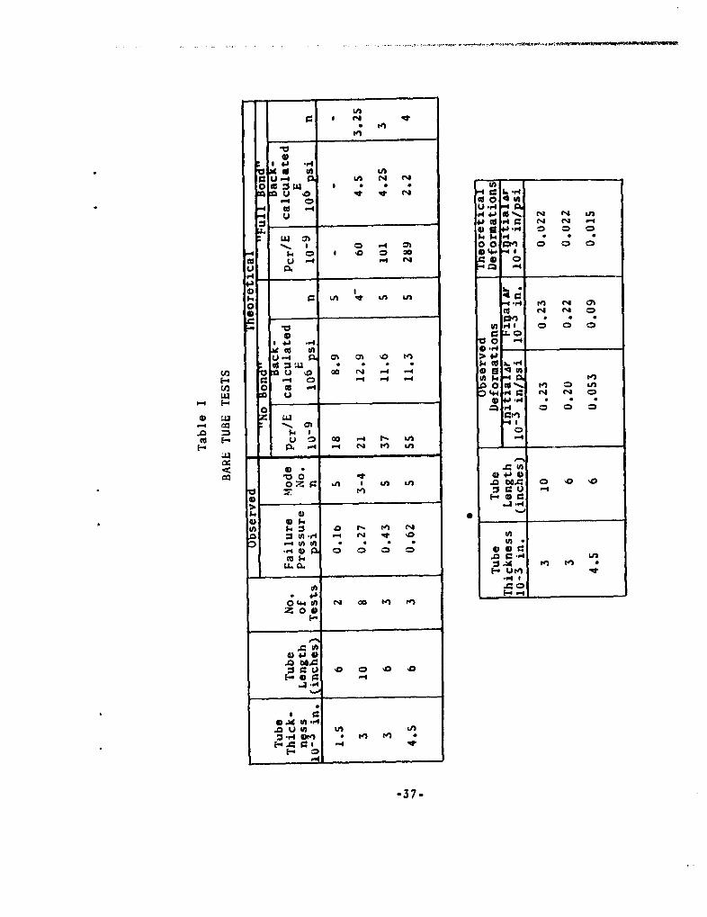
Additional tests on bare aluminum foil tubes wererun to eliminate, if possible, the apparentdiscrepancy betweenthe backcalculated and the conventional modulus of elasticityof the tube material (4.5 x 10⁶ psi versus 10 x 106 psi).Tubes with two different lengths, 10 inches and 6 inches, andthree thicknesses, one-ply two-ply and three-ply, were tested.The failure pressure and the failure mode were observed inall tests, and average tube deformations were determined insome tests by measuring, in a horizontal capillary tube, theamount of water displaced out of the water-filled aluminumfoil tube.
The results of these tests, presented in Table I,were correlated with the cylindrical shell buckling theory.Equation (9). when minimized for Pcr/E in terms of n. yields,for a given situation, a critical buckling value (Pcr/E)m inand a critical buckling mode ncr. With experimental results
-13-

expressed in terms of observed Pcr and n the modulus ofelasticity necessary to explain the buckhiAg resistance canbe backcalculated, and the mode numbers compared (see alsoRef. (2)). The correlation was made both for the "full bond"theory of tube action, where it was assumed that full shearforces were transmitted across the glued joint(s), and forthe "no bond" theory, which assumed no bond stress at all toact between the plies. These calculations are also presentedin Table I.
It becomes apparent from the table that the "nobond" theory is most nearly correct, as it leads to goodagreement between theory and experiment. The fact that thebackcalculated modulus is somewhat too high in all cases ofmulti-ply tubes must be due to some shear being transmittedacross the glued joint, and to some fixation at the ends notconsidered in the theory, which assumes "simple" end supports.
In conclusion, the agreement between theory andexperiments was good if the tubes were hypothesized to actas series of unconnected single-ply tubes. Apparently theglue was much too soft in comparison with the aluminum toforce the multi-ply tube to act like a solid tube in bending.
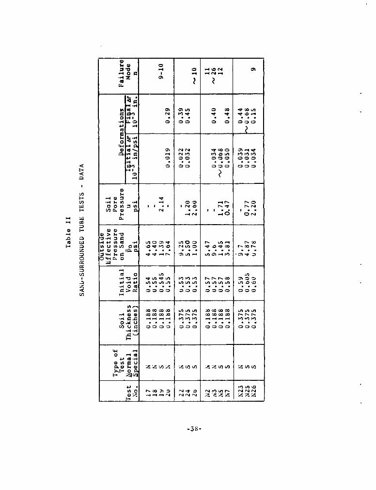
3. Further Tests on Sand-surrounded Tubes
The additional tests described in Reference (2) onOttawa sand-surrounded tubes were undertaken to obtain moreevidence supporting the arching theory, which originally hadbeen based on only one very limited series of tests. Later,similar tests explored the effect of the soil density uponthe behavior of the sand-surrounded tubes, and are reportedherein for the first time.
The testing equipment and method were as describedin Reference (1), Appendix L, with two modifications asfollows: First, loose sand was obtained by dropping it intostanding water and tapping the mold slightly, rather thantamping the sand as described for obtaining dense sand. Sincethe lateral pressure of the loose sand was insufficient topush the membrane into position, a vacuum device was used topull the membrane back against the mold. Second, a method
-14-

was devised to obtain a measure of the average radial deforma-tion of the tube: The total volume change of the aluminumfoil tube was measured in a horizontal capillary tube. Thismethod also allowed stopping of the failure process at anydesired time by closing off the outflow of water: therebyconserving the sample in a state of beginning failure forlater inspection. Thus in these tests, the failure pressureand failure mode, as well as the average deformation of thetube with applied load were observed.
The data obtained in these tests are presented inTable II. For completeness, Table II includes the data alreadypresented in Table III.of Reference (2).
Failure of these soil-surrounded tubes was firstrecognizable by a rapid increase in the measured volume changes.If the "drainage" line was not closed, water continued squirt-ing out of the end of the capillary tube at constant appliedpressure, and eventually visible failure patterns developedin the sand, as shown in Figure 9a taken from Reference (1).Prevention of large deformations by closing the line permittedinspection and evaluation of the tube failure pattern in manytests. This pattern consisted of one or more narrow creases,as shown in Figure 9b taken from Reference (2). The portionof the tube circumference involved in a single crease or thedistance between adjacent creases, divided into the circum-ference, was defined as the experimental mode number n.
4. Tests on Grout-surrounded Tubes
To investigate other combinations of soil-surroundedtubes, a suitable soft, plastic soil was sought. Consolidatedsoils were excluded from consideration because of the diffi-culties inherent in building a sample of the desired size andshape. The use of a compacted sample was also considered un-desirable because of the complexities of its shear-strengthcharacteristics. The search then turned to materials whichcould be poured and would subsequently solidify. From amongthese materials, AM-9 grout was chosen as the most versatilesince its strength and gelling characteristics can be controlledwithin wide limits by the concentration of the various chemicalsmaking up the mixture.
-15-

AN1-9 is the trade name of a chemical grout manu-factured and marketed by the American Cyanamid Company. Itsstrength characteristics are controlled by the concentrationof the main chemical, AM-9. Gelling is started by the ad-dition of a small quantity of a catalyst, and the gelling timeis controlled by the concentration of a retarder which isalready in solution when the catalyst is added.
In the present tests, 9 per cent and 18 per centAM-9 concentrations were used, The amounts of the trace chemi-cals (which are denoted by non-chemical abbreviation) were0.4 per cent DMAPN, 0.5 per cent AP (the catalyst), and zeroper cent.0.005 or 0.010 per cent of FeC (retarder) for approxi-mately 2-1/2, b, or 10 minutes of gelling time, respectively.In the tests described in this section, the grout alone wasused as "soil" surrounding; grout-saturated Ottawa sand wasused in another series of tests described in the next section.
To determine the mechanical characteristics of thegrout, vane, unconfined compression, and hollow-cylinder buck-ling tests were run. The results, some of which are presentedin Figure 10, may be summarized as follows:
(i) The grouts behaved as ideally cohesivematerials, i.e., the confining pressure had no in-fluence on the properties. This result suggeststhat the grout had no gas-filled void spaces, andhence that Poisson's ratio is 0.5.
(ii) The modulus of elasticity was 30 psi forthe 18 per cent solution and 6.7 psi for the 9 percent solution.
(iii) The shear strengths of the two groutswere appreciably different in the vane and the un-confined compression tests. In the vane tests, theywere 360 psf and 100 psf; in the unconfined tests,680 psf and 144 psf, for the stronger and weakersolution, respectively.
Two wall thicknesses and two grades of grout wereused in the grout-surrounded tube tests. The samples wereprepared and tested like the samples using loose sand, alsoemploying a vacuum arrangement to pull the membrane back.
-16-

Further, since after failure of the aluminum tube the groutcylinder was still in excellent condition, it was slippedover a fresh tube and re-used in a second test. During theslipping-on, the new tube was supported by a tightly fittinginside mandrel. No systematic difference between the twotests with the same grout cylinder could be detected; infact, the results were generally very similar. After thesecond test, the grout cylinder could still be used in ahollow "soil" cylinder buckling test.
Failure apparently took place in the form of over-all buckling of the sample, with one buckle developing in-itially, followed by others if more water was allowed toflow out of the tube.
The results of these tests, in terms of failurepressure, failure mode, and average radial deformations dur-ing the test, are presented in Table III. The strengthswere very low compared to the strengths of the sand-surroundedtubes, as could intuitively be expected for this less compe-tent "soil" surrounding. Consistent with this, the width ofthe buckles was much larger in these tests than in the testsusing sand. The average radial deformations, on the otherhand, both as far as initial slope and final value are con-cerned, were quite similar to those observed in the testswith sand.
5. Tests on Grout-sand-surrounded Tubes
Because of the low strength of the .1-9 grout aloneand the associated apparent tendency of the grout-surroundedtubes to fail in over-all buckling, a stronger "soil" withcohesive properties was desired for use as tube surrounding.The choice fell on 9 per cent AM-9-saturated Ottawa sand asbasically fulfilling the specifications set forth at thestart of the previous section, notably that of pourability.This material, which will henceforth be called grout-sand,was prepared by pouring M-9 of relatively long gelling timeinto the mold, adding and tamping the sand while the solutionwas still liquid, and letting the mixture gel. The voidratio of the soil was around 0.54.
The elastic and strength properties of this grout-sand were determined in triaxial and hollow-cylinder tests.
-17-

The triaxial tests were essentially undrained, since in therelatively short testing time (maximum 1/2 hour) no liquidwas pressed out of the samples. Some of the stress-straincurves of these tests are shown in Figure lla, and a Mohrdiagram of the strength resuks is shown in Figure lib. Thestress-strain curves are quite steep at the very start, butflatten out very soon and maintain an almost constant slopeover a large portion of the curve. The Mohr diagram suggestsan overconsolidated material with a normally consolidatedfriction angle of 360 and a maximum past pressure of about25 psi.
Hollow soil cylinder tests were performed in thetesting apparatus used for the hollow sand cylinder testsdescribed in Appendix K of Ref. (1). The tests were runon cylinders with 1-inch inside diameter and nominal wallthicknesses of 1/4 inch and 1/2 inch. The samples failed ina manner very reminiscent of the failure of hollow sandcylinders: compare Figure 12a to Figure 8a taken from Ref.(1). Moreover, the cohesive nature of the "soil" allowedinspection of the failed sample in cross section, shown inFigure 12b, giving conclusive proof of the failure modehypothesized in Figure 8b, also taken from Ref. (1).
With no inside pressure, Lverage observed outsidefailure pressures were 21 psi and 52 psi for the two wallthicknesses. Writing Equation (3), the equation for hollow-cylinder arching of a soil having both cohesion and friction,for each wall thickness and substituting the experimentaldata, two equations in c and # were obtained. Simultaneoussolution of the equation yielded c = 12 psi and #= 26.30as the strength parameters necessary to explain the observedbehavior. These strength parameters were additionally veri-fied by tests in which 1/2-inch thick hollow cylinders failedat an inside pressure of 10 psi and an outside pressure of83 psi. Drawing the strength envelope defined by this c and4 into the Mohr diagram, Figure llb, the agreement betweenthe two types of tests, for the pressure ranges used, isseen to be excellent, considering the fact that the cylinder-arching theory allows only two parameters c and 4, whereasthe broken enveloperesulting from the triaxial tests is morecomplicated.
-18-

Additional hollow cylinder data for the grout-sand,including failure pressures and phenomena at failure as wellas deformations, were obtained on cylinders after they hadbeen used in the soil-surrounded tube tests. The averageobserved failure pressure (neglecting premature local fail-ures which tended to occur) of 19.5 psi for a cylinder with0.812-inch inside radius and 0.375-inch wall thickness agreedvery well with the previous data. The total average radialdeformation of the inside surface at failure was approximate-ly 0.045-inch or 5.5 per cent of the radius. Moreover, thedeformation versus applied pressure curves generally exhibiteda more-or-less straight portion sloped at 0.0022*inch per psi.Assuming thin-ring behavior for the median plane of the ring,this corresponds to a modulus of elasticity of 1800 psi,which is in general agreement with the moduli found in tri-axial tests.
A substantial number of tests with this grout-sandsurrounding the two-ply aluminum foil tube were run. Experi-mental difficulties, the solution to which had to be foundby trial and error methods, affected a number of the earliertests. Moreover, the results of the tests which were con-sidered successful still showed appreciable scatter, such thatthe same phenomenon had to be observed at least twice toassure the existence of a trend.
The results of all these tests are presented inTable IV. Included are the apparently unsuccessful tests(1 to 5, and 11), since some of the information gained inthese tests still has potential value. Typical deformationversus pressure curves are shown in Figure 13, separated intoa low and a high pressure range.
At the start of the test, the deformations remainedvery small, as shown in Figure 13a. At a certain pressure,however, the deformation increased suddenly by an order ofmagnitude, but regained an equilibrium condition at constantapplied pressure. If the sample was taken out of the pressurecell at this stage and investigated, it invariably showedthat the aluminum tube had failed by developing one or morebuckles, even though no failure was discernible from theoutside. Thus this point was defined as the "tube failure"point.
-19-
If the sample was reloaded at that time, leavingthe original, buckled tube in place it generally showed adeformation curve resembling that of Test 8, Figure 13b, reach-ing failure at about 19.5 psi. Such behavior is very similarto that of unsupported hollow cylinders of the same materialand geometry. Two exceptions to the normal behavior wereobserved: see Figure 13b. Sample 6, upon reloading, showedagain quite stiff behavior, up to its previously establishedfailure pressure of 9 psi, then turned onto a steeper deforma-tion-versus-pressure curve, and finally failed at 24 psi.Test 10, the only test which was not interrupted after tubefailure, exhibited the usual phenomena up to that point, thenfollowed a slope corresponding to "soil alone" arching action andfailed at 27 psi.
To summarize the deformation data, three completelydifferent phases were generally observed: At first, thedeformations increased very slowly, amounting to about 0.04 -
0.06 x 10⁻³ inch per psi initially and 0.6 - 1.0 x 10³ inchat tube failure, more-or-less independent of the failurepressure. At tube failure, a sudden large deformation oc-curred, presumably as part or all of the load originallycarried by the tube was transferred to the soil cylinder.Further deformations were much larger, averaging about 1.7x 10⁻³ inch per psi, indicating that the soil cylinder alonecarried the extra load.
The strength results can now be summarized as0 follows:
(i) Premature tube failure, which was mainlydue to poor quality of the grout-sand near the bottomof the sample, occurred between 1.7 and 3.6 psi out-side pressure, but mostly between 2.0 and 2.7 psioutside pressure.
(ii) In good tests, the aluminum tube failedat outside pressures between 8.0 and 11.8 psi.
(iii) With the "failed" tube left inside, thesample sustained further pressure increases up toabout 19.5 or 25.5 psi. Presumably the finalfailure occurrred at 19.5 psi if the tube had failed
-20-

in such a way that it did not enhance the strengthof the sample and at 25.5 psi if the tube hadfailed in tuch a way that it continued to contributeto the resistance of the sample.
Data on tube failure modes were obtained from a numberof tests, It was difficult to obtain these data, since thelarge deformations associated with mobilization of the soilstrength after the tube failure tended to destroy the originalfailure mode of the tube. Thus, to get this information, thetest had to be stopped after tube failure and the mode datataken before pressures could be reapplied to the sample. Thesedata indicated a crease width of about 5 mm, corresponding toa mode number n of about 26, for tube failures between 8.0and 11.8 psi. For premature failures at 2.0 to 3.6 psi, thecrease widths averaged 11 mm, corresponding to n - 12.
To summarize these data of grout-sand surroundedtubes, the most important finding is that the aluminum tubesfailed at pressures which were in all cases below the failureof the surrounding soil alone. Thus failure of the tube didnot initiate over-all failure, but constituted merely the stagein the process of mobilization of resistance at which thestiffest component failed, since it acted in a brittle fashion.The sample as a whole sustained higher stresses which in generalequalled the failure pressure of the soil cylinder alone, butshowed definite indications in two cases that the aluminumtube, even in its "failed" state, helped to sustain loads.
-21-
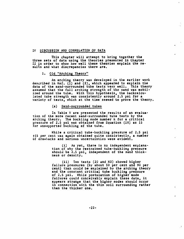
IV DISCUSSION AND CORRELATION OF DATA
This chapter will attempt to bring together thethree sets of data using the theories presented in ChapterI! in order to show how well these theories explain the re-sults and what discrepancies there are.
1. Old "Arching Theory"
An arching theory was developed in the earlier workdescribed in Ref. (1) and (2), which appeared to explain thedata of the sand-surrounded tube tests very well. This theoryassumed that the full arching strength of the sand was mobil-ized around the tube. With this hypothesis, the backcalcu-lated tube strength was consistently around 2.5 psi for avariety of tests, which at the time seemed to prove the theory.
(a) Sand-surrounded tubes
In Table V are presented the results of an evalua-tion of the more recent sand-surrounded tube tests by thearching theory. The buckling mode number n for a criticalpressure of 2.5 psi was obtained from Equation (10) as 15for unsupported buckling of the tube.
While a critical tube-buckling pressure of 2.5 psi±15 per cent was again obtained quite consistently, a numberof drawbacks and serious uncertainties were evident.
(i) As yet, there is no independent explana-tion of why the restrained tube-buckling pressureshould be 2.5 psi, independent of the sand thick-ness or density.
(ii) Two tests (20 and N3) showed higherfailure pressures (by about 50 per cent and 90 percent) than could be explained by the arching theoryand the constant critical tube buckling pressureof 2.5 psi. While postulation of higher modefailures could conceivably explain these data, itappears strange that the higher modes should occurin connection with the thin soil surrounding ratherthan the thicker one.
-22-

(iii) The evidence from comparison ofbuckling modes is inconclusive, mainly becausemost of the observations were for special testswith high pore pressures, for which the bucklingmode seemed to be about 10. Only two contradictoryobservations exist for normal tests, one of n - 1i,the other of n - 26 for the test exhibiting excep-tionally high strength.
(iv) Most seriously a strain discrepancyexisted, in that the strains deemed necessary todevelop full arching in the soil (determined frommodulus of elasticity considerations as well asfrom measured deformations in the hollow sandcylinder tests) were roughly 100 times higher thanthe strains actually measured at failure of thesamples. An explanation advanced in Ref. (1)Appendix L, which involves the difference of thestress histories of the sand in soil-surroundedtube tests and hollow soil cylinder tests is un-satisfactory in view of the order of magnitude ofthe discrepancy.
(b) Grout-surrounded tubes
Grout-surrounded tube samples failed in a mannerstrongly suggesting an over-all buckling failure. Moreover,inspection of the sample showed that the grout obviously didnot fail in shear. Thus it has to be concluded that the arch-ing theory does not pertain to these tests.
(c) Grout-sand-surroundedtubes
Finally, it becomes evident that the grout-sand-surrounded tube tests cannot be fitted to the arching theoryFor while the outside pressures associated with failure of thetube were in the same range as the highest pressures measuredin sand-surrounded tubes, at that pressure only the tube (butcertainly not the grout-sand) had developed its full potential.This was clearly shown by the rapid increase in deformationafter tube failure, which indicated that the load was trans-ferred from the failing tube to the soil, and by the much
-23-

higher failure pressure of the sample as a whole.
Thus it has been proven that at least for this grout-soil-tube configuration, the combined strength of the soil andthe tube was not attained, but that the tube failed firstbecause of its brittleness. Contradicting this statement,however, are the two tests (S6 and SIO) in which, even afterdeformations as large as 5 per cent, the tubes seemed tocontribute to the strength; this suggests the validity ofthe arching theory for a "large-deformation" condition incertain cases.
(d) Conclusion
It is concluded that the drawbacks of the archingtheory are severe indeed, and that determined efforts shouldbe made to find new theories to explain the data of the testson soil-surrounded tubes.
2. "Over-all Buckling" Theory
Since it appeared that over-all buckling of thesample was the controlling mode of failure of the grout-surrounded tubes, the theory for this situation has beenworked out in Chapter II and numerically applied to the wallthickness and moduli of elasticity of the grout.
Table VII compares observed values and values pre-dicted by this theory for the failure pressure and the bucklingmode of the grout-surrounded tubes. The following can bededuced from this comparison:
Very good agreement, both of critical pressures andfailure modes, exists for the 0.188-inch grout surrounding,concurring with the observed impression that this type offailure was indeed the controlling one in these tests. Theagreement may be further improved if the rubber membrane isincluded in the grout thickness, as was done in Reference (2)for the sand-surrounded tubes. Then the predicted criticalpressures would be 0.59 and 1.23 for the two grades of grout.
-24-

For the 0.375-inch grout thickness, the theoreticaland experimental values disagree. The observed failure pressureis lower than predicted and the mode number is higher. Arobable cause of the disagreement is the fact that the simpleuckling theory is only a rough approximation for thick rings,
and for a combination of materials of such radically differentproperties (the moduli of elasticity are in a ratio of roughly106:1). The errors attributable to both these uncertaintieswould be larger for the thicker than for the thinner soilsurrounding. It is therefore conceivable that the good agree-ment for 0.188-inch grout thickness was purely a fortuitousresult of cancelling errors, and that this type of failuremode is actually the controlling one for both wall thicknesses.On the other hand, the disagreement for the 0.375-inch wallthickness may be an indication that the failure mode is chang-ing or has changed to a different mode. This question cannotbe treated here, but will be taken up later.
In conclusion, there are strong indications thatthis failure theory is valid for failure of the tube combinedwith thin rings of extremely soft material. For any othersoil surrounding, the critical buckling pressure for thisfailure mode would be extremely high, so that other typesof failure would occur first.
3. Buckling of an Elastically Supported Ring
This interaction theory hypothesizes:
(i) The soil around the tube behaves verymuch like an elastic medium around a rigid circularinclusion. The condition is somewhat modified bysmall deformations of the inclusion.
(ii) Tube failure occurs in the form ofbuckling of an elastically supported ring.
Hypothesis (i) allows calculation of the pressureacting on the tube from the known outside pressure, by theelastic behavior theory developed in Chapter II and based onthe "elastic" properties of the soil. Then the coefficientof soil reaction k and the failure mode number n can be
-25-

calculated from the known tube-failure pressure. The modenumber n can be compared to the available data on failuremodews, and k can be correlated with the test conditions, i.e.,soil type and density, wall thickness and soil effectivepressure. The criteria for the applicability of the theoryare agreement of observed and backcalculated mode numbersand, ultimately such good correlation of the elastic soilconstant k to the test parameters that k could be predictedcorrectly for different parameters.
(a) Sand-surrounded tubes
Based on the calculations in Chapter II, the pa-rameters of the elastic soil ring action were chosen as
Pi/Po - 1.15 for 0.375-in. sand thickness
Pi/Po = 1.09 for 0.188-in. sand thickness
Thus the soil inside pressurespi were calculated from theknown Po, and Pi =Pcr = Yi + u. The k and n correspondingto the elastically supported tube buckling theory were thencalculated by Equations (14) and (15). The results of thesecalculations are shown in Table VI.
Since the straining characteristics of a sand arestrongly dependent upon the effective pressure in the sand,the resulting k and n values were then plotted versus Pj.(Figure 14). Unfortunately, for all "normal" tests, i.e.,tests without pore pressures acting on the tube, k and n werecalculated from Pi in the first place. Consequently, thesolid-line curves of Figure 14 are just curves of the mathe-matical relationships of k and n to Pi over the range of the"1normal" tests, and represent experimental evidence only forthe range of the "special" tests, i.e., tests in which partof the pressure applied to the tube was in the form of porepressure. The location of the points along the curves (i.e.whether Pi was large or small), does represent experimentalevidence.
-26-

Comparing experimental and theoretical mode numbersU (in Table VI and Figure 15), reasonably good agreement isfound in all cases, Three of these cases had a theoreticaln of 12 and an average observed n of 10, one was 16 versus11, and one 22 versus 26. More data, especially from testswith high mode numbers, would be desirable. One additionalobservation of a high mode number not recorded in Table VI,is the one shown in Figure 9b, but unfortunately it is notknown for certain whether it is from Test 20 or 22.
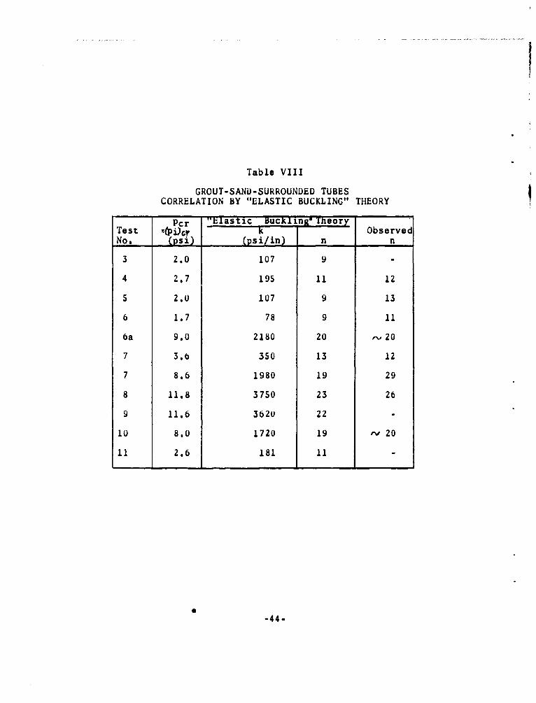
(b) Grout-sand-surrounded tubes
For this soil, the outside and the inside pressureson the soil ring were taken as the same because of an esti-mated Poisson's ratio of close to 1/2. Thus the calculationof k and n from the tube failure data shown in Table VIII,is based directly on the observed outside pressuresof TableIV.
Since the pore pressures in these tests were unknown,the evaluation is in terms of total stresses, and all pointsin the plots of k and n versus Pi would be on the theoreticalcurves, bunched in one group for the successful tests and ina second group for the premature failures. The comparisonbetween theoretical and observed mode numbers in Table VIIIand Figure 15 is very gratifying. While individual differencesare appreciable, probably mainly because of difficulties inmeasuring the crease widths accurately, a high and a low group,corresponding to the two classes of observed failures, areclearly distinguishable, and all data points fall into theright group.
(c) Grout-surrounded tubes
Since the over-all buckling theory failed to explainsatisfactorily the behavior of the tube with a 0.375-inchgrout surrounding, this situation was also considered in thelight of the "elastically supported tube buckling" hypothesis.The result of the computations is shown in the last twocolumns of Table VII.
-27-

I
The resulting k values are extremely low, whichmight have been expected for a tube-supporting material assoft as these grouts. Comparison of the mode numbers reveals,however, that the calculated values are appreciably higherthan the observed ones. Since the n values calculated fromthe over-all buckling theory are lower than observed, oneexplanation of the behavior of the-se samples might be that itrepresented a transition from the over-all buckling to theelastically supported tube buckling typo of failure.
(d) Summary
The application of the elastically supported tubebuckling theory to the strength behavior of the sand andgrout-sand-surrounded tubes showed great promise and, further-more, did not lead to any major discrepancies. On the otherhand, a number of points require further clarification:
(i) Upon what is the coefficient of soilreaction k dependent? The evidence indicates thatit was more-or-less independent of the soil density,that it was in the same range of values for sand andsound grout-sand tubes, but that it varied greatlywith the soil effective pressure in the "special"sand tests, and with the soil soundness in the grout-sand tests.
(ii) While the theoretical and observed modenumbers n showed quite good agreement, the bunch-ing of the observed values into a high and a lowgroup, without intermediate values, seems significantand, in fact, represents a deviation from the theoreti-cal results. As far as the sparse data indicate,this phenomenon was observed both in the sand andthe grout-sand tests. In the sand tests, "special"tests with a large fraction of the applied pressurein the form if pore pressure fall into the low-ngroup. The others, i.e.,"normal tests and "special"tests with low pore pressures, fall into the high-ngroup. Among the grout-sand tests, all low-n failuresfall into the group classified as "premature failures,"
-28-

induced by a weakening of the grout-sand at the samplebottom due to faulty production of the sample;failures with sound grout-sand were all of the high-ntype. This fact that only high-n and low-n failures,but none in between, were observed, points out thestrong tendency not considered in the theory in itspresent form, of the tube to fail in certain pre-ferred modes.
(iii) The same bunching was also observedfor the backcalculated coefficient of soil reactionk, especially in the grout-sand tests.
4. Conclusions
It should again be emphasized that this is an inter-im report on studies which are as yet unfinished. One import-ant result of the preparation of the report has been to clarifywhere we stand in our understanding of the problem, and topoint the way to future studies. The following paragraphscontain the tentative conclusions reached at this time.
The thin-walled grout-surrounded tubes failed inover-all buckling. Thick-walled grout-surrounded tubes devi-ated appreciably from that type of behavior. The deviationmay have been due to gross inaccuracies in the theory forcylinders as thick as these, or, since the deviation seemedto be in the direction of elastically supported tube buckling,the failure may have represented a transition between the twotypes of failure.
The sand-and grout-sand-surrounded tube failureshave been correlated with both the arching and the elastical-ly supported tube-buckling theories. Since each of thesecorrelations has its strong and its weak points, the questionof whether any of these theories, a combination of them, orpossibly still another theory is applicable, is undecidedat this time.
Ultimate failure of the grout-sand tubes was de-scribed either by the hollow cylinder strength theory (soilalone acting) or by the large deformation arching theory,
-29-

the latter in cases when even the failed tube seemed to helpin sustaining the load up to ultimate failure.
-30-

I
V PLANE STRAIN APPARATUS
In a new phase of the research on soil-surroundedtubes, it is desired to test tubes buried under a horizontalsoil surface. The new testing device designed and built forthis purpose is described in this chapter of the report.I)esign drawings and photographs of the finished device areshown in Figures 16 and 17.
1. Dimensions of Soil Mass
The same tube will be used for these tests as wasused in the symmetrical soil-surrounded tube tests. This tubehas a diameter of 1.625 inch, and was tested with 6-inch and10-inch lengths. Considering the situation of the buried tubein cross section, to minimize the effects of the soil boundarieson the behavior of the tube, soil dimensions of five timesthe tube diameter are widely used and were chosen here, result-ing in a soil area of 8 x 8 inches. On the other hand, fora tube of a length of four to five times the diameter, theeffects of the end conditions on the phenomena at mid-lengthare negligible. Thus, since the tube can be as long as thesoil mass, a soil length of 8 inches is sufficient and therebya cubical soil mass of 8-inch side length was chosen.
2. Loading Scheme
One design specification was that the device shouldallow independent control of the pressures and/or displace-ments on as many faces of the soil mass as was feasible. Tothis end, various schemes of loading by pistons and by pressur-ized rubber bags were considered. It was found that rubberbag loading has a number of advantages: The exact distributionof the pressure is known--it is uniform. Further, a tube canbe buried close to the loaded surface without danger of loadconcentrations on the surface (positive or negative) due tothe presence of the tube. Finally, the soil can move freelywithout any side friction developing. One important disadvantageis, however 9 that deformations cannot be measured as easilyas with a piston loading arrangement. Nevertheless, it wasfound desirable to use rubber bag loading on as many faces aswas practicable.
-31-

The final design of the device represents a compro-mise between what would be desirable and what it is possible tobuild and operate efficiently. Basically the device is a rigidclosed box designed to contain a soil sample of cubical shape,8 x 8 x 8 inches. For future reference, the three sets offaces are called top and bottom, sides, and ends, respectively;the position of the tube is imagined to be horizontal, parallelto the sides and consequently perpendicular to the ends.
One set of faces, the ends, are unyielding, thuscreating a plane strain condition in the plane perpendicularto the tube axis, as was the case in the soil-surrounded tubetests. The load on these faces cannot be measured.
The top of the soil sample is loaded by a pressurizedbag to ensure uniformity of pressure. It is possible tomeasure vertical deflections of the top either by insertingsmall rods through the top plate to make contact with themembrane, or by measuring the total amount of water beingpressed into the bag as a measure of the average deflection,as has been done up to now for the tube interior. A rigidplate bounds the soil at the bottom. The sides of the soilcube are loaded by pressurized bags.
3. Considerations Relating to Sample Preparation
For preparation of the sample, one end piece isremoved and the box is oriented with the open face up. Thetube is then in a vertical position, guaranteeing uniform soilconditions all around it. Since the pressure on the top facewill always be equal to or larger than the side pressure, noallowance has to be made for outward displacements in thatdirection; consequently the membrane can rest against the topplate during placement of the soil and will separate from itupon application of the load. Conversely, lateral expansionhas to be allowed on the sides; to make this possible, theside membranes are backed up by thin Lucite plates duringplacement of the sand, and the plates are retracted after apositive pressure to hold the sample in place has been appliedto the bags.
4. Special Features
Reduction of the friction forces on the rigid faces
-32-

is attempted by means of rubber mOmL.oneS and silicon greasebetween the membranes and the wall. 'i is method was usedwith excellent results by Dr. Rowe at the University ofManchester, Lngland (private communication). The method isemployed on the box bottom to allow unrestricted lateralexpansion, and on the box ends to allow vertical deformationsto develop without mobilization of high vertical shear stressescausing a loss in vertical load.
To check upon the effectiveness of the frictionreducing arrangements, the box bottom is designed as a loadcell consisting of two plates separated by four strain-gagedlegs. This load cell checks how much of the load applied atthe top arrives at the bottom; it thus indicates how much islost because of side friction and allows experimenting withother friction reducing procedures should the one plannedprove unsuccessful.
The three rubber bags are shaped essentially in theform of a closed box, with a large hole in the middle of oneface. They are made either by cutting and rejoining sheet-rubber (called dental dam) into the desired shape or byrepeatedly dipping a Lucite block into a Latex solution.All bags are connected to the box in such a way that the sealsdo not have to be broken in each test.
The "slider assemblies" shown in Figure 16A and16D separate the top and the side bags from each other,The assemblies have to be moved during the test by the sameamount as the rest of the sides move to eliminate any lateralconstraint of the sample.
S. Tube Supports
The tube supports have been thought out only farenough to prove their feasibility, but have not yet beendesigned in detail. Two basic types are considered. Forthe first type, the tubes are closed and sealed at the ends,but are connected to the outside by a thin plastic tube.This allows application of positive or "negative" pressuresto the inside of the tube and measurement of volume changesas a feflection of the tube deformation. A second solutionis to support the tube by thin Lucite rings at the ends; holesare provided in the box ends to observe and measure directlythe deformations of the tube.
-33-

BIBLIOGRAPHY
(0)- Contract No. AF 29(601)-1947, "Preliminary Design Studyfor a Dynamic Soil Testing Laboratory." Report AFSWCTR-61-58 contains Appendices K. L, M and N to the finalreport for this project.
(2) R. V. Whitman and U. Luscher (1962). "Basic Experimentinto Soil-Structure Interaction," ASCE Jr. of the SoilMech. & Found. Div., Dec. 1962.
(3) Kirkpatrick, D. M. (1957), "The Condition of Failurein Sands," Proc. of the 4th Int'l. Conf. on Soil Mech.i Found. Eng.
(4) Timoshenko S. (1936), Theory of Elastic Stability,McGraw Hill Book Company, Inc., New York.
(5) Timoshenko, S. (1941), Strength of Materials, Part II,D. van Nostrand Company, Inc., New York.
(6) Hetenyi, M. I. (1946), Beams on Elastic Foundations,Univ. of Michigan Press, 196.
(7) Bjerrum, L. and Kummeneje, 0. (19(.l),."Shearing Resistanceof Sand Samples with Circular and Rectangular CrossSections," Norwegian Geotechnical Institute, Pub. No. 44.
-34-

LIST OF SYMBOLS
A - area of ring
a a-•-* coefficient of tube rigidity
B a a constant
c - cohesion
E a modulus of elasticity, Es of soil, Eal of aluminum
h - tube thickness
hs a soil thickness
h' - equivalent tube thickness
I a moment of inertia
I' - equivalent moment of inertia
j a concerning the jth layer (subscript)
k - coefficient of soil reaction
4o - coefficient of lateral soil pressure at rest
L - unsupported tube length
M - bending moment in ring
N a normal force in ring
n - mode number
ncr - critical mode number
p - applied pressure, Pi inside pressure, po outside pressure
- average applied pressure
p' I p + c cot
-35-

Pcr - critical buckling pressure
Q - shear force in ring
r - radiuss ri inside radiuso ro outside radius
u - radial displacement of the soil
x - cricumferential ring coordinate
y - radial displacement of tube
E - strain; subscripts as for G"
- friction angle
V- Poisson's ratio
normal stress, E radial stresst tangential stressSaxial stress
equal stress in all directions of the plane
f- central angle
-36-
LI)
r4
V t) LI)
as~ u 6 *n N
0 go wo u2 0 u 0 C:L -
ý000')r0 0 0 L
4 co -4 4 u -. -4 0
Li0 e 0 -
S L) le LI) LI)
0'#14 0c0c
V ~0u 4. >5 0j
WI U nou 0 00 N -4 -4 0 i -0ulE- r - 0 4-4 C)m-4-0
to 0 cc J2 00- t'o 0ý LI
U3 cc4 0 0 0
4) LULU0)00 Q 4
to co -4 N Pt LA) N
10 0 0 41 aoZ 7 ) Ln LI) LI .0 bc. 0o 0~
a .4
41 0
U)40 r. W') NtfA l. P-4 N -e '0U
.- 4Ul *n (* * *u)
-4.5 4) a
Z.54
I-I
ZU 0 0 0
4 1 0 ) 5
r-. u
-4 _ _3_Ar._ __4
.37-
-4 0 r -4 w4eq -4
u0i cb (m Ln 0 00 -it 0 L
0 *4 * 0*H.L 0 0 00Q 0 0 00
0. La,.
0 ~ 00 04't00 000lP4 i9-0 " NI .n D LM rn .4j P40 00C C 000 000D
HH
0-to -4 k_ MH
00) * ckf *.$ -W0 41
Hf .11. 4) a * * s164 LU C
U0 0
w MU ,.4-J~ (n.O.4 LIn 0 CDm L0C r'- Lf - r- 0H a IA nu fl) V Oilt) ýo *' 10 eLn 0 - .t o ýDv0 t 0r-Z o. 4)4 ip. C * . . . .*
0 0 4--4- (Li) 0)~-t~~~
(a 0 -L't LA --!t- *. LfnJ~i )tn t)F't r- r- r-- 00 n =
4-A -,q +4j Ln Ln Ln In LA LII Ln tfn 1 dn n L O
W n0 00 00 x 000LnJ 00 (O00 000nLF4) a 00 0 t I-r 00 0 0 r -r
= = -4 -4.'
0 -14 u ** ****W)u a 00 00=CD0 000 0a)0 0
.H.
o-tu
P.~ 0kG>,E 0 06
4-'r *n ý)
IA ___ __ __0_ _______A_ _N
4) 4 4 -4ýsl -38-,

k -4~ ta w
be 0 a c-u-r. =___go__ ___
aJ 41$ Vu 13
o 4 0 0
D -40-4
P-4 -0-
*-r4 0 r. 00 1 LIn LIn .9co~"U-
Mn 1-44 L/) r- N LI) 1- 0D 4 0 00
0 rI W) . . I0 .,w41 0 0 0 0 0 0 0D 0 0
*J
W 4- -4
ul 0) D
m co 00l m4 . m
CD r0C -
La
M. 0 LL
o~r (M$ 0~l 0 0" "44-~4 W 0 0n 0 0 0n 00 00 LI) LI) "I "
* U-
00 0004oo U u )
-3-

* 0*
00
>0
a0 S. a~ cc44 a
.. % p) Ur lu a Im'4- .0 -40 Si 5 0
tou rm0E~ ý1 Ua0 bc U 00
-40C)l~ -I Lf Ln) 5* .4 P- Si 0ý -4 S.
E- 0
1.4 ~~r 00 (~I~~~ 0 ~ 000l
LII I- I. I~ *t I I 1 *
:3 to 1I 0 000 0 0 -40C> P-4 C0
to -A4 CUq -.4-
-4 LU4
cU z 0 .Z 00 .4
cc0 *-A CD 1 0 0 0 1O 1 -4
1- 4 0U. 01 11 1- 4- 1 0 1
a- 0 D4% 0 0 0 0 00
0~ 04
U) 0
0 o 0Q, 0 Q0t-0 %Q 1 0 0 10 0 40
rý ~ ~ ~ C 0) .9 lý4P4ý " - 4 -4
0U.
4j a) I- %nL nLnL f n AL nLMAd n
~0 cc
cc .0ca cac
-40-

Table V
SAND-SURROUNDED TUBE TESTS - CORRELATION BY "ARCHING THEORY"
Soil InitialTest Thickness Void p p1 totNo. (inches) Ratio - u #2 Pi i + u
17 4.65 - 2.24 2.24
18 4.40 - 2.07 2.12 2.120.1ub8 0.545
19 1.39 2.14 (398) 0.67 2.81
20 7.64 - 3.69 3.69
22 9.25 - 2.47 2.473.75
24 0.375 0.53 5.50 1.20 1.47 2.67(39.50)
26 1.00 2.60 0.27 2.87
N2 5.47 - 2.71 2.712.02
N3 9.6 - 4.75 4.750.188 0.575 (38.4*)
N5 1.45 1.71 0.72 2.43
N7 3.81 0.47 1.89 2.36
N23 9.70 - 2.81 2.813.45
N25 0.375 0.60 4.87 0.77 1.41 2.18(380)
N26 0.78 2.20 0.23 2.43
Theoretical buckling mode with Pi x 2.5 psi: n - 15, for un-supported buckling.
-41-

Table VI
SAND-SURROUNDED TUBE TESTS-CORRELATION BY "ELASTIC BUCKLING" THEORY
" Initial - - -
Test Thickness Void pi tot kNo. (inches) Ratio _6 Pi/5o 3i -Pi+u Dj s/in•] n
17 4.65 - 5.06 5.06 690 14.8
18 4.40 - 4.80 4.80 620 14.50.188 0.545 1.09
19 1.39 2.14 1.52 3.66 360 12.6
20 7.64 - 8.33 8.33 1860 19.0
22 9.25 - 10.63 10.63 3040 21.5
24 0,375 0.53 5.50 1.20 1.15 6.32 7.52 1520 18.1
26 1.00 2.60 1.15 3.75 380 12.8
N2 5.47 - 5.96 5.96 950 16.10.188 0.575 1.09
N3 9.6 - 11.05 11.05 3280 22.0
NS 1.45 1.71 .1.58 3.29 290 12,0
N7 3.81 0.47 4.15 4.62 570 14.2
N23 9.7 - 11.15 11.15 3340 22.0
N25 0.375 0.60 4,87 0.77 1.15 5.60 6,37 1090 16.6
N26 0.78 2.20 0.90 3.10 260 11.6
-42-

01-
to u
(u m Ix `4
o fo
.0 - * ("
U.4 -u .4tU0 4.b :3-u co-r4
V) -y _ _ _ _
on
$4
in ~ LAnOC' '
*'- 0 *
"" 0 C 1
EnI4.. in.ul3 i
'-' U)
> 1E-
1-43
I
Table VIII
GROUT-SAND-SURROUNDED TUBESCORRELATION BY "ELASTIC BUCKLING" THEORY
Pcr "Elastic bLuckling°TheoryTest =(Pi)cr k ObservedNo. (psi) (psi/in) n n
3 2.0 107 9 -
4 2.7 195 11 12
5 2,0 107 9 13
6 1.7 78 9 11
ba 9.0 2180 20 • 20
7 3.6 350 13 12
7 8.6 1980 19 29
8 11.8 3750 23 26
9 11.6 3620 22
10 8.0 1720 19 ' 20
11 2.6 181 11 -
-44-

FIGURE I EQUILIBRIUM OF SOIL RING
FIGURE 2 SOIL AROUND RIGID INCLUSION - PROBLEM-45-

1.50Shs=.375in., ro/ri =1.46
-= 3700)
20
0 0.25 0.5 0.75 1.0
(a) p, /po versus (Tt/0r (constant throughout the ring)
04'
I •61
0.2
0V.
0- .4" " •)V = 0.5 •
b 01.0 1.5 2.0 2.5 3.0r/ri
(b) Exact solution for rigid inclusion
FIGURE 3 SOIL AROUND RIGID INCLUSION - SOLUTIONS
-46-

5
4
hs =0.375 inl
3
22
2-
I I'• : 0188 in
10 t02 30
Es [psi]
(a) (Pcr)min versus E.
.50
S.25.E_
, 0 5I0 15 20
rI=i 1+1z ýs Eo[x 1O'9irr•]0E.
(b) (pcr/Eol)min versus I
FIGURE 4 OVER-ALL BUCKLING OF COMPOSITE; SAMPLE
Soil Surrounding 2-ply Aluminum Foir Tube.47-

p' p+ccot$()' a + c cots
S¢cot 11 .=• • - x
Also: cot Z 2
01A '011
4
FIGURE 5 MOHR DIAGRAM FOR COHESIVE SOILS
dv dx dx
dx x j
FIGURE 6 BUCKLING OF ELASTICALLY SUPPORTED RING
-48.

okI
-m -
CD
00
0~0~
0-' Cf0 0
(0 0
[!s-- J )
Q 49-
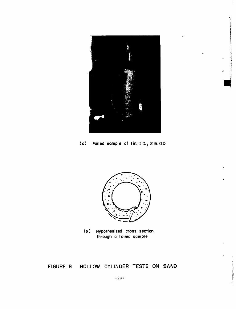
(a) Foiled sample of lin. I.D., 2in. O.D.
(b) Hypothesized cross sectionthrough a foiled sample
FIGURE 8 HOLLOW CYLINDER TESTS ON SAND
-30)-

Uq
(a) Failed sample with 3/8 inchwall thicknessLarge deformations
(b) Aluminum tube after failure(3/8 inch soil thickness)Only small deformations allowed
/k/
Cross Section
FIGURE 9 FAILURE PHENOMENA OF SAND -SURROUNDED TUBES
-*s1-

6 6
Unconfined Compression Failure Vane (average of 4 tests)
¶94 Z'STest sto ed
2
0 000 20 30 40 00 100 20° -300
Axial Strain [%J Angle of Rotation
(a) 18% AM-9
1.2 1.2
Unconfined Compression Failure Vane (average of 4 tests)(average of 2 tests) 0
- 0.8/ 0.8
€,@1
S0.40.
a.
10 20 30 40 00 100 200 300Axial Strain [%] Angle of Rotation
(b) 9% AM-9
FIGURE 10 PROPERTIES OF AM-9 GROUT-52-

800
0; ~3Opsi
60(T a T • PSIs
20/E •--840 psi
O0 1 2 3 4 5 6 7 8
Axial Strain [%.]
(a) Stress- Strain Curves
60
triaxiol tests.
L.j
00 20 40 60 80 100 120
( [Psi]
(b) Mohr diagram
FIGURE II TRIAXIAL TEST ON GROUT-SAND
.53.

I
a. View of foiled cylinder
b. Cross section throughfailed cylinder
FIGURE 12 HOLLOW CYLINDER TESTS ON GROUT- SAND
-34 -

pa (Psi] f02.5 5 7.5 10 17-5
(( ) L W P E S S U REL O
R A N G E
0E0-IO
r.5
.O5l
.007
oi lure Pressure
5 10 PO [psi) 15 20 25 30
(b) HIGH PRESSURE RANGE
6o (previously loaded"-c .00 • •* •, to 9.0 psi )
.010C.0
E (previously loadedo0 to ,,. 8 psi) \'02 .0o0
10 (firs loading)
r .030
0I..
.0401
FIGURE 13 DEFORMATIONS OF GROUT-SAND- SURROUNDED TUBES-55-

5000
Symbols Dense Loose /0.375 in. wall thickness A A
0.188 In. wall thickness o 0 A
"C A0
0
IOWoA
04-C 0O
500 Theoretical" line
- All points on this lineare from normol" tests,oll others from "speclor•Rst
200 1 si12 5 10 20
S[psi]
25S20 f
z 15 •
1012 5 10 20Pi[psi]
FlIGURE 14 SAND- SURROUNDED TUBES
Correlation by "EloStic Buckling" Theory
-56.-

30+ Grout-sand tests +
A o Sand tests asAAJ on Fig. II 0+
25 /
/€ 20
E
,15 +/_S~+o
+ 010-t.0
o A
5 10 15 20 25Back-calculated Mode Number n
FIGURE 15 CORRELATION OF MODE NUMBERS
-57.

Other sections see Figs. 13 8, C, DList of components see Fig. 13 E
D IQ Q25D
0.5\0.2
VETIA SETO - cl
FIUE9.5DAIG0F LN TAI PAAU
-M57-

D D
V 0
C c8
.- 990
AJ
VERTICAL SECTION B-B
FIGURE 16B DRAWINGS OF PLANE STRAIN APPARATUS
-59-

S1.600-1. 4.800 1.600
110
Q750oo 8 _____0750 B
- . -- 7970 0.015
i.8- //
://
HORIZONTAL SECTION C -C
FIGURE 16 C DRAWINGS OF PLANE STRAIN APPARATUS
-60-

+ + +@ ÷ + -I +- + + + I-
i - ++ +- +
+ +
C + +
+ + ++ +I
TOP +
FIGR + DS
+ +
4--- 6 .500 i- --+ +
4-. ++ +
+ __ _ _ __-___ _ _
J• (® (Identica on
-i other side)]
TOP VIEW D-D
FIGURE 16D DRAWINGS OF PLANE STRAIN APPARATUS
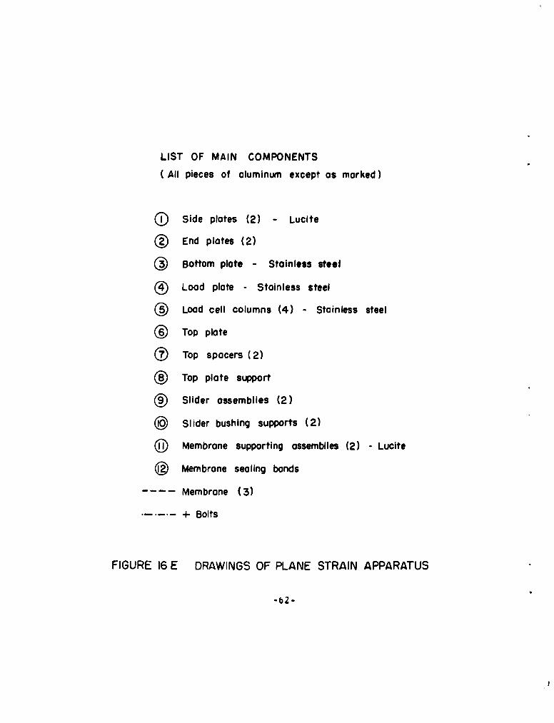
LIST OF MAIN COMPONENTS
(All pieces of aluminum except as marked)
( Side plates (2) - Lucite
(© End plates (2)
(•) Bottom plate - Stainless steel
Load plate - Stainless steel
® Load cell columns (4) - Stainless steel
®• Top plate
(• Top spacers (2)
®• Top plate support
) Slider assemblies (2)
@ Slider bushing supports (2)
@D Membrane supporting assemblies (2) -Lucite
(@ Membrane sealing bonds
Membrane (3)
+ Bolts
FIGURE 16 E DRAWINGS OF PLANE STRAIN APPARATUS
-*b -

One end andtop removed
End removed
End removed
FIGURE 17 PHOTOS OF PLANE STRAIN APPARATUS-63-

APPENDIX A
65

Appendix A
STRESSES AROUND A RIGID CIRCULAR INCLUSION
A plane strain solution for the case of a rigidcircular inclusion in a uniformly stressed plane is presentedhere. Figure 2 of the main body has illustrated the problemand given the notation. The problem is point symmetrical;radial and tangential stresses are therefore principal stresses.
Radial direction: Strain = du
Tangential direction: strain =
Axial direction: strain = 0
Stress-strain relationships:
6o= v({G>-Gi.),•) .
".=fo+ )V2 v ,V ,
6 v(l-.')7 kv f(/9v
t 1 i /vz)2
(
VlF +4- A,
66

After simplification
(/.v)(i- 2k')
(7ra0- ) + -
SAlso:
Lquilibrium equation: . r + - 0 (1)di-t
After substitution and simplification:
r 2 u + r - U = 0 (6)
By substituting u - r, the general solution of (6) is obtainedas
U - c.% + 4r
Boundary conditions:
At inner boundary (r = ri): u(ri) - 0
c1 + c 2 ri 2 = 0
At outer boundary (r-. co ): displacements of uniformstress field:
'I~j - Z-G [(/- P*) v + j
""4 (/-v- 2v')
67
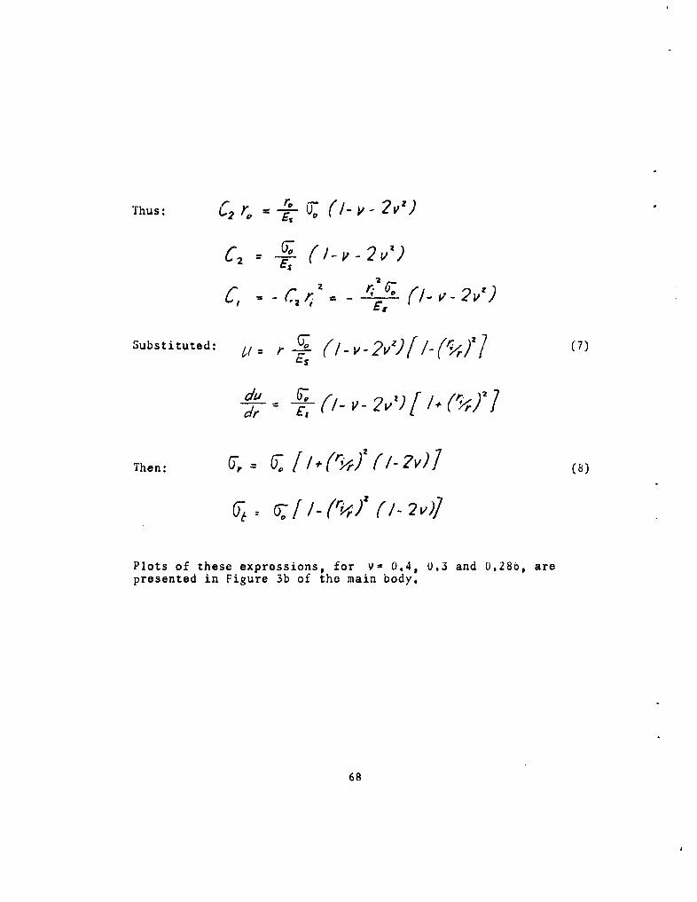
Thus: C2'r =-t7 •(2 rv -Cc
C2 - (-v-2 I v)
Substituted: .= r- 0 v-2v(( 2 (7)
0 -' - /
Then: 0 7. 2 (?v)
Plots of these expressions, for v= 0.4, 0.3 and 0.28b, arepresented in Figure 3b of tho main body.
68

APPENL)IX B
69

Appendix B
BUCKLING OF AN ELASTICALLY SUPPORTED RING
A solution for buckling of an elastically supportedring is presented here. Figure 6 of the main body illustratesthe problem and clarifies the notation. The solution is quitesimilar to fletenyi's (Ref. (6)), but here the equilibriumequations are formulated for the deformed shape rather thanthe original shape of the ring. Another reference which wasused for the present derivation was Timoshenko (Ref. (5)).
Applied pressure: P- 5 * kyEquilibrium equations:
Radial direction: pdx'- d V ds'
where d,'- dx. 4d,, = J, (4i- d A
d /
dx r ro, a -
and N - normal force in ringQ - shear force in ringA - area of ring
then: jP AF r dXTangential direction:
70

dt dx
moments: d1, 6,Vx' O K ?,, (a- 'h,)where ,I - bonding moment in ring
a.n (/_ ,Z¢dM
A number of simplifications are introduced at this point:
(a) In the corrective terms (those which representthe consideration of deformations), forces andmoments are replaced by those which would bepresent in the unbuckled ring; that is, inthese terms, N - No - rf, Q - Qo - 0, M - Mo - 0.This step corresponds to a neglecting of correc-tive terms of second order, which is a commonprocedure in problems of this kind.
(b) The term H/VAE is very small compared to I.
Thus 1 -Af- 1.
With these simplifications, the equilibrium equations are:
-~ ~ ~ w.k _A ,A /
- dx
Eliminating Q and N, the following equation is obtained:
d dM -'. d "0 ' (Bl)#p r 7x
71

The differential equation of bending of a circular arc is,according to Hetenyi and Timoshenko:
S- (B2)dx" r
If this equation and its third derivative are substituted in(B1) to eliminate M, one obtains, after substituting d/d .':
dS ( d'-j56y r3
where a - T,
Exploring the possibility of a periodic buckled shape, y - B
sin nf, is substituted into Lquation (12). The result is:
n h(2+* •) + n (koi/) o (13)
Excluding from consideration the. solution n 0 yields:
-n41_n (2,-/•6) + kre + -o/ 0
This equation can be further treated by formulating a solutionfor n2, then finding the smallestp for which n has a realsolution. Alternatively, the equation can be solved forand minimized with respect to n. By either method of solution,the result is:
/7 = 4-_' _ - / (B4)
72
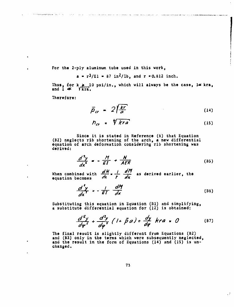
For the 2-ply aluminum tube used in this work,
a = r 3 /El - 87 in 2 /lb, and r -0.812 inch.
ThusI for k 1 10 psi/in., which will always be the case, 1- kra,and 1 4c i-i- .
Therefore:
Pc (14)
Since it is stated in Reference (6) that Equation(B2) neglects rib shortening of the arch, a new differentialequation of arch deformation considering rib shortening wasderived:
d 7Y (BS)dx' a -L F AER
When combined with dM Wdfl as derived earlier, the
equation becomes 7x r dx
/ dli (B6)
Substituting this equation in Equation (Bl) and simplifying,a substitute differential equation for (12) is obtained:
el Y ~ kra 0 (7
The final result is slightly different from Equations (B2)and (B3) only in the terms which were subsequently neglected,and the result in the form of Equations (14) and (15) is un-changed.
73
TDR-63-6
DISTRIBUTION
No. cy s
HEADQUARTERS USAF
2 Hq USAF (AFOCE), Wash 25, DC
1 Hq USAF (AFRST), Wash Z5, DC
1 Hq USAF (AFRNE-A, Maj Lowry), Wash 25, DC
1 Hq USAF (AFTAC), Wash 25, DC
1 USAF Dep, The Inspector General (AFIDI), Norton AFB, Calif
1 USAF Directorate of Nuclear Safety (AFINS), Kirtland AFB, NM
1 AFOAR, Bldg T-D, Wash 25, DC
MAJOR AIR COMMANDS
1 AFSC (SCT), Andrews AFB, Wash 25, DC
2 AUL, Maxwell AFB, Ala
2 USAFIT (USAF Institute of Technology), Wright-Patterson AFB,Ohio
AFSC ORGANIZATIONS
1 AFSC Regional Office, 6331 Hollywood Blvd., Los Angeles 28,Calif
I ASD (ASAPRL, Technical Doc Library), Wright-Patterson AFB,Ohio
3 BSD (BSR), Norton AFB, Calif
3 SSD (SSSC-TDC), AF Unit Post Office, Los Angeles 45, Calif
2 ESD (ESAT), Hanscom Fld, Bedford, Mass
I AF M9l Dev Cen (RRR-T), Holloman AFB, NM
1 AFMTC (MU-135), Patrick AFB, Fla
2 APGC (PGAPI), Eglin AFB, Fla
2 AEDC (AEOI), Arnold Air Force Station, Tenn
KIRTLAND AFB ORGANIZATIONS
AFSWC, Kirtland AFB, NM
1 (SWEH)
30 (SWOI)
5 (SWRS)
1 US Naval Weapons Evaluation Facility (NWEF) (Code 404),Kirtland AFB, NM
74

TDR-63-6
DISTRIBUTION (cont'd)No. cvs
OTHER AIR FORCE AGENCIES
2 Director, USAF Project RAND, via: Air Force Liaison Office,The RAND Corporation (RAND Library), 1700 Main Street,Santa Monica, Calif
ARMY ACTIVITIES
2 Director, Ballistic Research Laboratories (Library), AberdeenProving Ground, Md
1 Hq US Army Air Defense Command (ADGCB), Ent AFB, Colo
1 Chief of Engineers, Department of the Army (ENGEB), Wash 25,DC
2 Office of the Chief, Corps of Engineers, US Army (ProtectiveConstruction Branch), Wash 25, DC
1 Director, Army Research Office, Arlington Hall Sta, Arlington, Va2 Director, US Army Waterways Experiment Sta (WESRL), P.O.
Box 60, Vicksburg, Miss1 Commanding Officer, US Army Engineers, Research & Develop-
ment Laboratories, Ft Belvoir, Va
NAVY ACTIVITIES
1 Chief, Bureau of Yards and Docks, Department of the Navy,Wash 25, DC
1 Chief, Bureau of Ships, Department of the Navy, Wash 25, DC
1 Commanding Officer and Director, David Taylor Model Basin,Wash 7, DC
1 Commanding Officer and Director, Naval Civil EngineeringLaboratory, Port Hueneme, Calif
1 Commander, Naval Ordnance Test Station, Inyokern (Code 12),China Lake, Calif
1 Officer-in-Charge, Civil Engineering Corps Officers, US NavalSchool, Naval Construction Battalion Center, Port Hueneme, Calif
1 Office of Naval Research, Wash 25, DC
OTHER DOD ACTIVITIES
Chief, Defense Atomic Support Agency, Wash 25, DC
1 (Document Library)
2 (DASABS)
75

TDR-63-6
DISTRIBUTION (cont'd)
No. cy
2 Commander, Field Command, Defense Atomic Support Agency(FCAG3, Special Weapons Publication Distribution), Sandia Base,NM
1 Director, Advanced Research Projects Agency, Department ofDefense, The Pentagon, Wash 25, DC
1 Director, Defense Research & Engineering, The Pentagon,Wash 25, DC
10 ASTIA (TIPDR), Arlington Hall Sta, Arlington 12, Va
AEC ACTIVITIES
1 Sandia Corporation (Tech Library), Sandia Base, NM
1 Sandia Corporation (Tech Library), P.O. Box 969, Livermore,Calif
OTHER
1 Office of Assistant Secretary of Defense (Civil Defense),Battle Creek, Mich
1 Space Technc.Logy Labs, Inc., ATTN: Information Center,Document Procurement, P.O. Box 95001, Los Angeles 45, Calif
2 University of Illinois, Talbot Laboratory, Room 207, Urbana, Ill
30 Massachusetts Institute of Technology, Department of Civil &Sanitary Engineering, ATTN: Prof. R. V. Whitman, 77 Massa-chusetts Avenue, Cambridge, Mass
2 South Dakota School of Mines and Technology, ATTN: Prof. EdwinH. Oshier, Rapid City, South Dakota
2 University of New Mexico, AF Shock Tube Facility, Box 188,University Station, Albuquerque, NM
2 Armour Research Foundation, ATTN: Dr. Sevin, 3422 SouthDearborn St., Chicago 15, Ill
2 MRD Division, General American Transportation Corp., 7501North Natchez Avenue, Niles 48, Ill
1 National Engineering Science Co., ATTN: Dr. Soldate, 711South Fairoaks Ave., Pasadena, Calif
1 The Dikewood Corporation, 4805 Menaul Blvd., N. E.,Albuquerque, A4M
1 United Research Services, 1811 Trousdale Drive, Burlingame,Calif
1 University of Notre Dame, Department of Civil Engineering,ATTN: Dr. H. Saxe, Notre Dame, Ind
76
TDR-63-6
DISTRIBUTION (cont'd)
Z Stanford Research Institute, Menlo Park, Calif1 Stanford University, School of Mechanical Engineering, ATTN:
Dr. Jacobsen, Stanford, Calif
1 University of Washington, ATTN: Dr. I. M. Fyfe, Seattle 5, WashZ Purdue University, School of Civil Engineering, ATTN: Prof.
G. A. Leonards, Lafayette, Ind1 California Institute of Technology, ATTN: Dr. Paul Blatz, 1201
East California Blvd., Pasadena, Calif1 Paul Weidlinger and Associates, 770 Lexington Avenue, New
York Z1, NY
1 Official Record Copy (SWRS)
77

+1 4-4 P. -15-4 4
11 0 411 0 M
P4f ca, to~ 4)04
4)11- 4)0 W~ 4) 10 to 0)C V44.I toI~ ~
0~~tc V ) 'r20)
4)4 I I-Id4. M
8 V . I)- 4) 0
4104)E'0 4.0 4)
41 1 040) )4)
0) 0.0C ) 4
4 4 4-,
U\0 4)C) .0,)00 4
I ~ Io -
q? +5~U1' P4)04 .~C1I ~ )0
4). .C ,-k4S P.44)4) '4)to
00 1 1
lfl .14
Al CW" b
I0
C)4, I\ H I..H ) 0 ~ 'dA P.H
0 4)ýC to 14)
a H. .a H
~~J 0 04
0ý '- :01 0 v ) C), to 'k.
0 .4
C) 4-
0o P4 4)4 !0~4 0LOH4 N 1 4,-f CIO

43 11
00 0
4, 4,
q H N4:
04
440 4,0
PdD 4,ý
4- 4- 0 ,-
4' 41
0 0 0,q +)'Ad H 4
04,
HO 4) 444
4,4,0 4,4,
As 4'o Ho 4- 04,
4, 4, O0B B t41
____ ___ ___ ___ _4_ CS
4 , j 4>
![405 [EDocFind.com]](https://static.fdocuments.us/doc/165x107/577d38851a28ab3a6b97fb10/405-edocfindcom.jpg)