Unbalance and Induction Machines - serialsjournals.com · Unbalance and Induction Machines F F 61...
21
61 Unbalance and Induction Machines V. Ramakrishnan 1 , and S.K. Srivatsa 2 1 Department of EEE, Bharath University, Chennai - 600 073, India. 2 Department of ICE, St. Joseph's College of Engineering, Chennai - 600 119, India ABSTRACT: An unbalance in a three-phase system can be seen as the presence of a negative sequence. In induction machines (IM’s), even a small negative voltage will cause a large amount of negative sequence current. The negative sequence will cause a synchronous frequency second harmonic pulsation and unbalanced currents in the system. In induction machine, unbalanced 3-phase stator voltages cause a number of problems such as over heating, over current and thrust on the mechanical component from torque pulsation. Therefore, the machine torque, flux, and reactive power will have a 100 Hz pulsation. Unbalance condition appear that using active crowbar protection and direct torque control. The control strategy is validated by means of simulation. Induction Generator (IG) connected in the power system under balanced and unbalanced load, symmetrical and unsymmetrical components of voltages and currents are described. The definition of unbalance factor, harmonic content and synchronous frame unbalance theory are also analyzed. Experimental results under balanced condition are presented. Keywords: Balance and unbalance IM’s, negative and positive and neutral sequence. 1. INTRODUCTION Wind power is one of the most promising renewable energy sources after the progress undergone during the last decade. However, its integration into power systems has a number of technical challenges concerning security of supply, in-term of reliability, availability and power quality. An unbalance of voltage may occur on long distance power transmission lines as shown in figure 1[1]. It occurs not infrequently in the case of generating stations supplying mixed International Journal of Power Elecronics and Technology January-June 2011, Volume 1, Number 1, pp. 61–81
-
Upload
phungkhuong -
Category
Documents
-
view
218 -
download
3
Transcript of Unbalance and Induction Machines - serialsjournals.com · Unbalance and Induction Machines F F 61...

Unbalance and Induction MachinesF F
61
Unbalance and Induction Machines
V. Ramakrishnan1, and S.K. Srivatsa2
1 Department of EEE, Bharath University, Chennai - 600 073, India.2 Department of ICE, St. Joseph's College of Engineering, Chennai - 600
119, India
ABSTRACT: An unbalance in a three-phase system can be seen as thepresence of a negative sequence. In induction machines (IM’s), even a smallnegative voltage will cause a large amount of negative sequence current. Thenegative sequence will cause a synchronous frequency second harmonicpulsation and unbalanced currents in the system. In induction machine,unbalanced 3-phase stator voltages cause a number of problems such as overheating, over current and thrust on the mechanical component from torquepulsation. Therefore, the machine torque, flux, and reactive power will havea 100 Hz pulsation. Unbalance condition appear that using active crowbarprotection and direct torque control. The control strategy is validated bymeans of simulation. Induction Generator (IG) connected in the power systemunder balanced and unbalanced load, symmetrical and unsymmetricalcomponents of voltages and currents are described. The definition of unbalancefactor, harmonic content and synchronous frame unbalance theory are alsoanalyzed. Experimental results under balanced condition are presented.Keywords: Balance and unbalance IM’s, negative and positive and neutralsequence.
1. INTRODUCTIONWind power is one of the most promising renewable energy sourcesafter the progress undergone during the last decade. However, itsintegration into power systems has a number of technical challengesconcerning security of supply, in-term of reliability, availability andpower quality. An unbalance of voltage may occur on long distancepower transmission lines as shown in figure 1[1]. It occurs notinfrequently in the case of generating stations supplying mixed
International Journal of Power Elecronics and TechnologyJanuary-June 2011, Volume 1, Number 1, pp. 61–81

International Journal of Power Elecronics and TechnologyF F
62
polyphase and single phase loads. The predetermination of theperformance of three-phase induction motors under such conditionsis a matter of importance that there is a reduction in the maximumload which an induction motor is capable of carrying safely whensupplied with unbalanced voltages, but the extent of this reductionhas not received the attention which it merits.
It is carried out experiments on the performance of inductionmachines on unbalanced votages, but they have assumed that theload limit of the motor is reached when the current in one phasereaches its full load value, and hence their experiments underratethe performance of the motor [2]. It is treated the matter analyticallyand derived certain simple formulae to predetermine the output,but his results have not received conclusive experimentalverification. The various conditions of symmetrical components,unsymmetrical components, balance and unbalance conditions,positive, negative, zero sequence and harmonic pulsations, voltageunbalance theory and factor have been discussed. The output of thesimulation result has been verified by experimental calculation.Graphical method of resolving an unsymmetrical voltage systeminto two symmetrical systems is also described.
Figure 1: Physical Connection in the Power System
2. INDUCTION GENERATOR CONNECTED IN THEPOWER SYSTEM UNDER UNBALANCED LOAD
The unbalancing of the balanced voltages of the alternator waseffected in two ways: (1) by injecting into one of the phases of thealternator an opposing e.m.f. derived from the secondary of a

Unbalance and Induction MachinesF F
63
transformer whose primary was connected across the alternatorphase itself, this condition corresponding to pure unbalance of thestar voltages with no phase shift; (2) by injecting into one of thephases a quadrature e.m.f. obtained from the secondary of atransformer whose primary was connected across the other twophases, as shown in Figure 2.2
Figure 2: Diagram Connections, UTr, Connecting Transformers, AA, AB, AC,Line Ammeters, VAB, VBC, VCA, Line Voltmeter, WA, WB, WC,
Wattmeter’s, VA, VB, VC, Star Voltmeters
Measures were made of the star voltages, the line voltages, theline currents, and the power in each phase and the output. Themethod of procedure was to maintain a constant unbalance and loadthe motor gradually, taking all the readings until the currents farexceeded the normal value. While the unbalanced-phase voltage issmall, large negative-sequence currents can result due to lownegative sequence impedance of an induction generator. These largecurrents eventually can cause unbalanced heating (hot spots) inthe machine windings, which can potentially lead to failure.Unbalanced-voltage operation will also create a pulsating torquewhich produces speed pulsation, mechanical vibration, andconsequently, acoustic noise.
The tests were repeated for various degrees of unbalance. Thepractical experimental calculations are given in Experimental Resultschapter. As is well known, an unbalanced three-phase system maybe resolved into two balanced component systems, one of which

International Journal of Power Elecronics and TechnologyF F
64
has the same phase sequence or phase rotation as the unbalancedsystem, while the other has the opposite phase sequence. For thesake of brevity, we shall in what follows speak of the first balancedcomponent as the direct phase or direct rotational system, and ofthe second as the reverse phase or counter-rotational system.
The unbalance factor of a system is defined to be the ratio ofthe reverse phase voltage (or current) to the direct phase voltage(or current) and is frequently expressed as a percentage. Thegraphical method of relations connecting output and percentageunbalance is shown in Figure 3.
Figure 3: The Graphical Method of Relations ConnectingOutput and Percentage Unbalance
(A) When local losses equal to full load losses
(B) When current in an one phase reaches full load value

Unbalance and Induction MachinesF F
65
3. TURBINE SPEED CLASSIFIED IN TWO TYPESThe wind turbine technology can mainly be classified into twosections.
• Fixed speed wind turbine
• Variable speed wind turbineIn 2003, 46% of the wind turbines installed were variable speed
wind turbines with double fed induction generator and its marketshare is going to increase. It has several advantages over the othertypes.
Now days Doubly Fed Induction Generator (DFIG) stator of suchwound rotor machines is directly connected to the electrical gridand therefore, it is extremely sensitive to voltage disturbances dueto voltage sags [3]. When unbalanced sags occur, the main problemis that very high current, torque, power oscillations appear at doublethe electrical frequency forcing a disconnection. Such oscillation isprovoked by the negative sequence components injected by theunbalanced disturbance [4]. Unbalance condition appear that usingactive crowbar and direct torque control. A method based on adisturbance refection controller is proposed into compensate the2*ωe (ωe – electrical angular velocity) oscillation produced byunbalances, by adding a feed forward component to the currentcontrollers.
A control strategy is proposed by choosing certain currentreference values in the positive and negative sequences. So thattorque and the DC voltage are kept stable during such unbalancedsequences. Both rotor and grid side converter are considered;detailing the control scheme of each converter which consideringthe effect of the crowbar protection. The control strategy is validatedby means of simulation.
Unbalance load condition, to control the DFIG, on separatingthe positive and negative components of all the current and voltagesfor DC /AC converter both the grid side and rotor side[5]. But gridside converter control is not considered, to keep the DC bus stableis proposed, based on compensating the rotor power delivered bythe rotor side converter in the grid side converter.

International Journal of Power Elecronics and TechnologyF F
66
4. (A) SYMMETRICAL COMPONENTSFortes cue method of symmetrical components is used in calculationin this paper.
0XXX
+
−
= 2
2
1 1 11 13
1
A
B
C
Xa a X
Xa a
(1)
Where XA, XB, XC are the phasors of unbalanced phasor system.X0, X+ and X_ are phasors of symmetrical components (zero, positiveands negative sequence respectively and q = 1 < 120º is unit complexoperator.
The level of unbalance is described by current unbalance factor(more precisely known as sequence current unbalance factor), ρi,which is given as the modulus of ratio of negative to positivesequence currents (same as for negative sequence voltage unbalancefactor, ρv) as shown in Figure 4.
Figure 4: One Single-Phase Load Connected to Low Voltage
Moreover, in non-counterweighted systems the zero sequencecurrent (voltage) unbalance factor εi (εv) is defined as the modulusof ratio of zero to positive sequence currents (voltages).
εi = 100, 100o oI VI Vυ
+ +
× ε = × (2)

Unbalance and Induction MachinesF F
67
The analysis of a three-phase circuit in which phase voltagesand currents are balanced (of equal magnitude in the three phaseand displaced 120º from each other) and in which all circuit elementsin each phases are balanced and symmetrical is relatively single.Since the treatment of a single phase leads directly to the three phasesolution positive, negative and zero sequence system of threesuccessive application of ‘a’ will rotate through 360º as shown inFigure 5 [5].
Figure 5: Symmetrical Components
Positive and negative sequence impedance of a transformer oneequal and zero sequence is also equal to the positive sequenceimpedance provided these are a through circuit for the earth currentsand the compensating currents can flow: otherwise the impedanceis infinite.
(B) Unsymmetrical ComponentsUnsymmetrical faults which occur as single line to ground faults,line to line faults or double to ground fault cause unbalanced currentsto flow in the systems. The absence of a grounded neutral at thegenerator does not affect the fault current. It the generator neutral

International Journal of Power Elecronics and TechnologyF F
68
is not grounded zero sequence impedance is infinite and zerosequence voltage is indeterminate, but line to line voltages may befound since they contains no zero sequence components as shownin Figure 6.
Figure 6: Unbalanced Current Can be Resolved into under Balanced Condition
(C) Under Balanced ConditionThe DFIG is attached to the wind turbine by means of a gearbox.Stator windings are directly connected to the grid, which the rotorwindings are controlled to a back-to-back converter. The converteris composed of the grid side converter connected to the grid and therotor side converter connected to the wound rotor windings. Theconverter set points are established by the so called high levelcontroller. It user the knowledge of the wind speed and the gridactive and reactive power requirements to determine the optimumturbine pitch angle and the torque and reactive power set pointsreferenced to the converter. The rotor side converter controls thetorque and reactive power, which the grid side converter controlsthe DC voltage and grid side reactive power. The rotor sideback-to-back converter can control both reactive power injected bythe stator by controlling the rotor currents and the reactive powerinjected directly. To the grid with grid side converter, reactive powerto deliver through the stator which keeping a low or null reactivepower set point in the grid side converter.
Unbalance and Induction MachinesF F
69
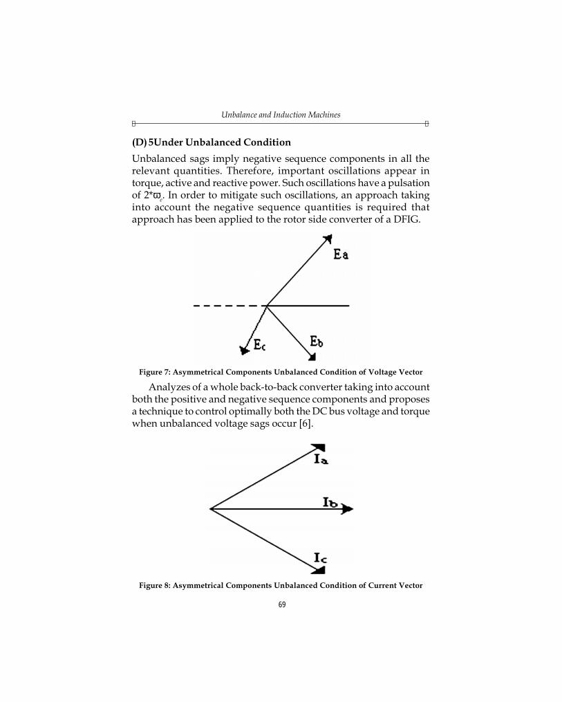
(D) 5Under Unbalanced ConditionUnbalanced sags imply negative sequence components in all therelevant quantities. Therefore, important oscillations appear intorque, active and reactive power. Such oscillations have a pulsationof 2*ωe. In order to mitigate such oscillations, an approach takinginto account the negative sequence quantities is required thatapproach has been applied to the rotor side converter of a DFIG.
Figure 7: Asymmetrical Components Unbalanced Condition of Voltage Vector
Analyzes of a whole back-to-back converter taking into accountboth the positive and negative sequence components and proposesa technique to control optimally both the DC bus voltage and torquewhen unbalanced voltage sags occur [6].
Figure 8: Asymmetrical Components Unbalanced Condition of Current Vector

International Journal of Power Elecronics and TechnologyF F
70
The positive and negative sequence components calculation isdone by using the Clarke transformation, rotating either ejωet ore–jωet, and finally applying a notes-filter of 2*ωe to eliminate theopposite sequence. PI controller is used, tuned according to internalmode control. For a time constant T, the parameters obtained yieldKp = L / T; Ki = R/T. for the rotor side voltages are limited accordingto the rotor side voltages can be applied using standard space vectorpulse with modulation technique.
5. PROBLEMS CAUSED BY VOLTAGE UNBALANCEThree-phase utility unbalance can be a problem in rural areas, whereinduction wind generators are likely to be located. In inductionmachines, unbalanced three-phase stator voltages cause a numberof problems, such as overheating, over-current, and stress on themechanical components from torque pulsations.
Therefore, beyond a certain amount of unbalance, inductionmachines must be derated or removed from the network. In thecase of a grid connected induction generator, this can exacerbatethe grid balance. In addition, any time generation is removed, itmeans less money for the generation company. In this chapter,quantification of unbalance and how to analyze unbalancedinduction machines is presented.
6. PER PHASE EQUIVALENT CIRCUIT UNBALANCES THEORYUsing symmetrical component theory [7], a three-phase system canbe represented as the sum of zero, positive and negative sequencecircuits. When the three-phase system is perfectly balanced, onlythe positive sequence is present. When the system is unbalanced,one or both of the zero and negative sequence will be present. For astar connected machine without a neutral connection, no zerosequence current will flow. Therefore, for the purpose ofperformance analysis of a star connected machine without a neutralconnection, the zero sequence can be ignored.
Induction machines are very susceptible to a stator voltageunbalance. This can be easily understood by using the per phaseequivalent circuit of a cage-type induction generator for the positive

Unbalance and Induction MachinesF F
71
and negative sequences, as shown in Figure 9. With any inductionmachine, the larger the slip speed between the rotor conductors andthe air-gap flux, the greater voltage and current impressed on therotor. This is easily seen in Figure 9(a), as the equivalent rotorresistance decreases with increasing slip.
Figure 9: Induction Machine Per Phase Circuit for(a) Positive Sequence; (b) Negative Sequence
The negative sequence voltage is rotating in the oppositedirection of the positive sequence. This gives rise to a flux componentrotating in the negative direction. This negative sequence flux isrotating counter to the rotor, which appears as a very large slip.
Therefore, the equivalent rotor resistance for the negativesequence is much smaller than the equivalent rotor resistance forthe positive sequence, shown in Figure 9 (b). Even a small amountof negative sequence voltage will give rise to a large amount ofnegative sequence current. This extra negative sequence current cancause over-heating, and it unbalances the stator currents.

International Journal of Power Elecronics and TechnologyF F
72
In addition to the unbalanced currents, there will also be aperiodic pulsation in the torque and reactive power. This pulsationwill occur at twice the synchronous frequency. This can beunderstood better using more advanced tools: space vectors and dqtheory.
7. DEFINITION OF UNBALANCE FACTORThere are many standards for defining the amount of unbalance fora three-phase system. Some methods focus on ease of calculation inthe field (usually ignoring phase shift), others are moremathematically rigorous. The National Electrical ManufacturersAssociation (NEMA), defines line voltage unbalance (LVUR) [8] as
( )max , ,ab Lavg bc Lavg ca Lavg
Lavg
V V V V V V
V
− − −(3)
where, VLavg = 3ab bc caV V V+ − (4)
This method has the advantage of being easily calculated in thefield, as it depends only on phase-phase voltage magnitudes.However, it does not account phase shift. In this research, the amountof unbalanced for a three-phase system is defined as the magnitudeof the negative sequence over the magnitude of positive sequence.This is called the “unbalance factor”2 and for voltage is denoted asvoltage unbalance factor( VUF) and for current as current unbalancefactor( IUF) Referring to Figure 9:
VUF = 2
1
s
s
VV (5)
The advantage of this definition of unbalanced is that it accountsfor both a magnitude unbalance (where one of three-phases is offnominal in magnitude) and a phase unbalance (where one of thephases is not 120 degrees separated). It should be noted that not allunbalances are created equal. A 5 % VUF for one system with anoff-nominal voltage (like a voltage sag in one phase) and a five

Unbalance and Induction MachinesF F
73
percent VUF for another system with a phase-shifted phase can affecta machine quite differently. However, the definition of is chosen asthe best overall method of quantifying unbalance. As an interestingside note, for a system with perfect 120 phase delay between phases,and in the case where there is an over or under-voltage condition ina single phase, then LVUR is approximately twice VUF.
8. SYNCHRONOUS FRAME UNBALANCE THEORYA three-phase unbalance will add a double synchronous frequencyharmonic to synchronous frame quantities. For example, a voltageunbalance (either by magnitude, phase, or in combination) in a50 Hz system will add a 100 Hz harmonic to all the synchronousframe voltages and currents. This in turn adds a 100 Hz harmonicsto the machine torque and power.
A space vector is defined as
Vs(t) = Va(t) + Vb(t)ej120 + Vc(t)ej240 (6)
These variables are shown as a function of time to emphasizethat they are instantaneous values. Each phase quantity can be saidto be equivalent to the sum of a zero, positive, and negative sequencecomponent, represented by the subscripts 0, 1 and 2 respectively.
Va(t) = Vs0 cos (ωsyn t + θ0) + Vs1 cos (ωsyn t + θ1)
+ Vs2 cos (ωsynt + θ2) (7)
Vb(t) = Vs0 cos (ωsynt + θ0) + Vs1 cos (ωsynt + θ1)
+ Vs2 cos(ωsynt + θ2 + 120) (8)
Vc(t) = Vs0 cos(ωsynt + θ0) Vs1 cos (ωsynt + θ1)
+ Vs2 cos(ωsynt + θ2 – 120) (9)
Substituting (7) through (9) in to (6), we get
( )sV t = ( )1 2( ) ( )1 2
3 ˆ ˆ2
syn synj t j ts sV e V eω +θ ω +θ+ (10)

International Journal of Power Elecronics and TechnologyF F
74
Here then it is seen that a space vector can be represented as asum, of two synchronously rotating vector: one proportional to thepositive sequence component, rotating in the positive direction, andanother proportional to the negative sequence component, rotatingin the negative direction. These two vectors will add constructivelyand destructively twice per revolution, thus causing the doublefrequency harmonic in torque and power.
The d and q components of the vs space vector are defined asthe scaled reflections of the space vector on to the dq reference frame(see Figure 7)
sdqV =120
240
2/3(
) d
jsd sq a b
j jc
V jV V V e
V e e θ
+ = +
+(11)
Substituting (7) through (9) into (10):
sdqV =1
2
( )1
( )2
3/2(
)
syn
syn d
j tsd sq s
j t js
V jV V e
V e e
ω +θ
ω +θ θ
+ =
+(12)
For a dq frame synchronized to the stator voltage space vector(“grid flux oriented”, see Chapter 4, θd simply the angle of vs.
Θd =( )( )
1 2
1 2
( ) ( )1 21
( ) ( )1 2
ˆtan ˆ ˆ
syn syn
syn syn
j t j ts s
j t j ts s
img V e V e
real V e V e
ω +θ ω +θ
−ω +θ ω +θ
+ +
(13)
Θd =1 1 2 21
1 1 2 2
ˆ ˆsin( ) sin( )tan ˆ ˆcos( ) cos( )
s syn s syn
s syn s syn
V t V tV t V t
− ω + θ − ω + θ
ω + θ + ω + θ (14)
This equation becomes quite complex to analyze when there isan unbalance (i.e., vs2 ≠ 0). Because the dq axes are aligned to analyzewith the stator voltage space vector, at all times. The d-axis voltage is
Vsd =2 21 2 1 2
1 2
(22/3 3/2
cos(2 ))s s s s
ssyn
V V V VV
t+ +
=ω + θ + θ
(15)
Unbalance and Induction MachinesF F
75
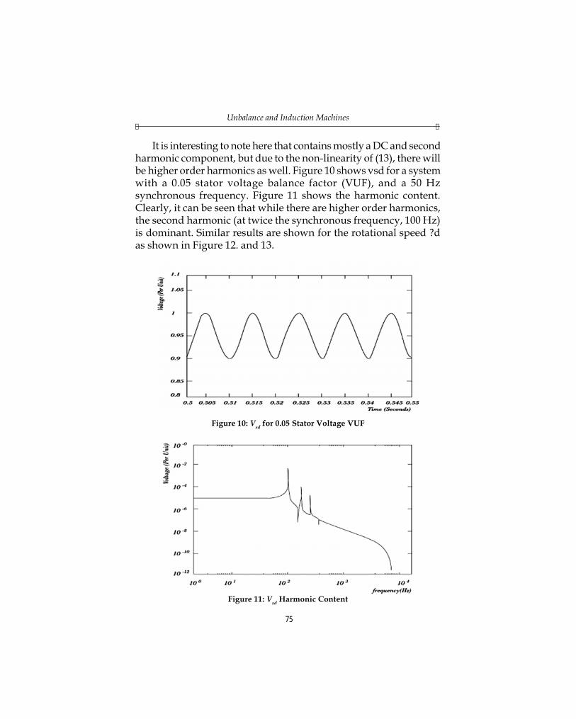
It is interesting to note here that contains mostly a DC and secondharmonic component, but due to the non-linearity of (13), there willbe higher order harmonics as well. Figure 10 shows vsd for a systemwith a 0.05 stator voltage balance factor (VUF), and a 50 Hzsynchronous frequency. Figure 11 shows the harmonic content.Clearly, it can be seen that while there are higher order harmonics,the second harmonic (at twice the synchronous frequency, 100 Hz)is dominant. Similar results are shown for the rotational speed ?das shown in Figure 12. and 13.
Figure 10: Vsd for 0.05 Stator Voltage VUF
Figure 11: Vsd Harmonic Content

International Journal of Power Elecronics and TechnologyF F
76
Looking at Figure 10 through Figure 12, it is then easy to seehow this second harmonic propagates through the entire circuit,causing second harmonic pulsations in the reactive power andtorque (active power).
Figure 12: d for 0.05 Stator Voltage VUF
Figure 13: d Harmonic Content
It’s shown then that higher order harmonics resulting frominstantaneous alignment can likely be safely neglected. Also, it maybe that the positive sequence alignment strategy may result in less

Unbalance and Induction MachinesF F
77
of the second harmonic disturbance, since it does not add any noisethrough ωd. However, this may be offset by the fact positive sequencealignment has a second harmonic in vsq. All things considered, theinstantaneous alignment is effective and simpler to implement. Formore discussion on unbalance for positive sequence alignment, see[9] and [10]
9. EXPERIMENTAL RESULTSThe test consisted in determining how far the induction motor iscapable of correcting the unbalance in the supply voltage. Inductionmotor on unbalanced supply through Lab Experimental IM’s valuesis given below.
A three phase star connected 440 Volt (line to line), 10 HP 50 Hzsix pole induction motor has the following constants in ohms perphase. R1 = 0.30 Ω/phase, R2 = 0.14 Ω/phase, Rm = 120 Ω/phase,X1 = X2 = 0.35 Ω/phase, Xm = 13.2 Ω/phase. For a slip s = 0.025(operation as a motor), compute I, VA, Im, I2, speed in r/min, Totaloutput torque and power, power factor, Total three-phase lossesand efficiency.
The applied voltage to neutral is
V1 =440 254.034 0 V/Phase;
3 3o Voltage =
As per U.S.A Standard value adopted in calculation,
Line to Line Voltage = 220V,
Phase Voltage value = 220 127 0º /3
V phase=
Z2 =2
20.14 0.350.025
R jX jS
+ = +
= 5.60 0.35 5.61 3.58ºj+ = Ω
Zm =(120)(13.2)
13.2 83.72º120 13.2
m m
m m
jR X jR jX j
= = Ω+ +
International Journal of Power Elecronics and TechnologyF F
78
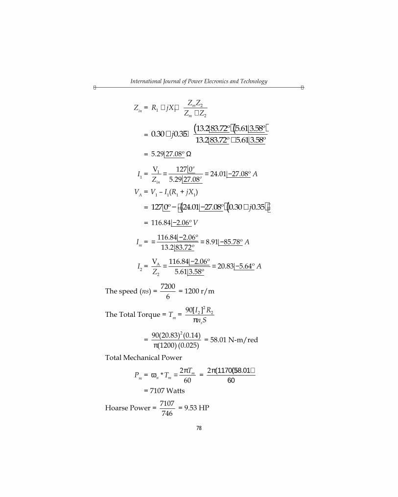
Zin =2
1 12
m
m
Z ZR jXZ Z
+ ++
=( )( )13.283.72º 5.613.58º
0.30 0.3513.283.72º 5.613.58º
j+ ++
= 5.29 27.08º Ω
I1 =1V 127 0 24.01 27.08º
5.29 27.08
o
oin
AZ
= = −
VA = V1 – I1(R1 + jX1)
= ( )( )127 0º 24.01 27.08º 0.30 0.35j − − +
= 116.84 2.06º V−
Im = 116.84 2.06º 8.91 85.78º13.2 83.72º
A−= = −
I2 =A
2
V 116.84 2.06º 20.83 5.64º5.61 3.58º
AZ
−= = −
The speed (ns) = 72006
= 1200 r/m
The Total Torque = Tm =2
2 290[ ]s
I Rn Sπ
=290(20.83) (0.14)
(1200) (0.025)π = 58.01 N-m/red
Total Mechanical Power
Pm = 2*60
mn m
TT πω = = 2π(1170)(58.01)60
= 7107 Watts
Hoarse Power = 7107746
= 9.53 HP

Unbalance and Induction MachinesF F
79
Power Factor (p.f) = cos θ;
where, θ = ∠V – ∠I rad, ∠XC = 1Cω
Q =2
2sin var, Watts,VV I P VI I RR
θ = = =
Q =2
2 varVVI I XX
= =
(θ) Lead indicates that θ is negative i.e., p.f. = 0.8 lead
Complex Power S = P + jQ + |S| ∠θ VA
Z = R + jX; XC = 1 ; XL LC
π = ω πω
Total losses in the motor
PLoss =2
2 21 1 2 2
33 3 WattsA
m
VI R I R
R+ +
= ( )23 116.84120
+3 (24.01)2 (0.30) + 3(20.83)2 (0.14) watts
= 1042 Watts
Efficiency = 71077107 1042
mm
m Loss
PP P
η = =+ +
= 0.872, 87.2% (Induction motor)
The efficiency of the 3-phase induction motor has beendetermined under balanced conditions. If any fault occurs in one ofthe phases, unbalance condition arises and hence the efficiency canbe determined only after bringing to balance condition. It wasconsidered desirable to observe experimentally what the resultingbalance voltage is when the unbalanced supply is corrected by meansof a reverse phase series booster, and how far this value agrees withthe direct phase component as obtained from the vector analysis ofthe unbalanced voltages.

International Journal of Power Elecronics and TechnologyF F
80
10. CONCLUSIONThus, a controller of doubly fed induction generator used in windturbine has to withstand disturbances, have capabilities discussedearlier, and keep turbine operational. It is also desirable to havecontroller, which can guarantee to perform despite known variationsin system parameters and wind.
DFIG Unbalance Compensation Control Design presents themodifications to the basic control that are designed to handle theunbalanced voltage. An unbalance in a 3-phase system can be seenas the presence of a negative sequence. In induction machines, evena small negative sequence voltage will cause a large amount ofnegative sequence current. The negative sequence will cause asynchronous frequency second harmonic pulsation in the systemand cause unbalance current.
The amount of torque pulsation and reactive power pulsationare almost linear function of voltage unbalance factor. This is anotheradvantage of using VUF to quantify unbalance but it was observedthat it is important for both reactive power and active power to becompensated. If only one at the loop is compensated, the statorcurrent will become very much distorted. Also it was observed thatthe compensation loops tend to decrease the total harmonicdistortion slightly. It may be worth further investigation.
First and foremost would be the grid side rotor converter. It maybe advantageous to implement a special control on this converter todeal with the extra harmonics that will be active on the DC link.Also, it may be possible to unbalance the current drawn from theconverter to complement the unbalance stator current to effectivelycompletely balance the current into the system though this may againimpact the DC link voltage. It is an area worth investigating. Inaddition, it should be possible to extend the compensation controlto dq control used in power systems, such as three-phasesynchronous rectifiers.
The induction motor is tested & verified at laboratory as perUSA standard and it gives the result as follows: Total Torque-58.01N-m/radian, Total Mechanical Power – 9.53 HP, Pf – 0.8 lead, TotalLosses in the Motor - 1042 Watts, Efficiency of the Motor - 82.2%.

Unbalance and Induction MachinesF F
81
Unbalance and Induction Machines presents and explains theproblems caused in induction machines when connected to anunbalanced supply. The mathematical impact of unbalance isexplained, tested in the lab, and the amount of unbalance isquantified.
REFERENCES[1] S. D. Rubira and M. D. McCulloch , “Control Method Comparison of DFWG
Connected to the Grid by Asymmetrical Transmission Lines”, IEEETransactions on Industry Applications, 36, No. 4, July/August 2000 .
[2] A. Von Jouanne and B. Banerjee , “Assessment of Voltage Unbalance”, IEEETransactions on Power Delivery, 16, No. 4, October 2001.
[3] YiZhou, Paul Bauer, Jan A. Ferreira, and Jan Pierik, “Operation of Grid-Connected DFIG Under Unbalanced Grid Voltage Condition”, IEEETransactions on Energy Conversion, 24. No: 1, 2009, pp. 240-246.
[4] Oriol Gomis-Bellmunt,Adria Junyent-Ferre,Andreas Sumper and Joan Bergas-Jane, “Ride-Through Control of a DFIG under Unbalanced Voltage Sags”,IEEE Transactions on Energy Conversion, 23. No. 4, 2008, pp. 1035-1045.
[5] Jaime. A. Peralta, Franciso de Leon, and Jean Mahserdjian , “Unbalanced MultiPhase Load-Flow Using a Positive-Sequence Load Flow Program”, IEEETransactions on Power Systems, Vol. 23. No: 2, 2008, pp. 469-476.
[6] Jesus Lopez, Eugenio Gubie, Pablo Sanchis, Xavier Roboam and Luis Marroyo,“Wind Turbines Based on DFIG under Asymmetrical Voltage Dips”, IEEETransaction on Energy Conversion, 23. No. 1, 2008, pp. 321-330.
[7] B. Wollenberg, A. J. Wood, “Power Generation Operation and Control”, JohnWiley & Son’s, New York 1984.
[8] C. Y. Lee, “Effects of Unbalance Voltage on the Operation Performance of athree Phase Induction Motor”, IEEE Transaction on Energy Conversion, 14. No:2, June 1999.
[9] H. S. Song, K. H. Nam (1999), “Dual Current Control Scheme for PWMConverter Under Unbalanced Input Voltage Conditions”, IEEE Transactionson Industrial Electronics, 46, No: 5, October1999.
[10] H. S. Song, K. H. Nam, “Instantaneous Phase-Angle Estimation Algorithmunder Unbalanced Voltage-Sag Conditions”, Generation, Transmission andDistribution, IEE Proceedings 147, Issue 6, , Nov - 2000, Page(s); 409-415.