UMS (Version 2.0) User’s Guide - American Megatrends Inc. - Home · • Microsoft® Windows®...
98
UMS (Version 2.0) User’s Guide MAN-UMS 05/12/2004
Transcript of UMS (Version 2.0) User’s Guide - American Megatrends Inc. - Home · • Microsoft® Windows®...
UMS (Version 2.0) User’s Guide
MAN-UMS 05/12/2004
UMS (Version 2.0) User’s Guide ii
© Copyright 1985-2010 American Megatrends, Inc. All rights reserved. American Megatrends, Inc. 5555 Oakbrook Parkway, Building 200,Norcross, GA 30093
This publication contains proprietary information which is protected by copyright. No part of this publication can be reproduced, transcribed, stored in a retrieval system, translated into any language or computer language, or transmitted in any form whatsoever without the prior written consent of the publisher, American Megatrends, Inc. American Megatrends, Inc. acknowledges the following trademarks: Intel® and Pentium® are registered trademarks of the Intel® Corporation. AMD, Athlon, and Athlon XP are trademarks of the Advanced Micro Devices Corporation. Sun and NFS™ are trademarks of the Sun Microsystems Corporation. Microsoft, Windows, Internet Explorer and MS-DOS are registered trademarks of the Microsoft Corporation and Active Directory is a trademark of the Microsoft Corporation. IBM, AT, VGA, PS/2, and OS/2 are registered trademarks and XT and CGA are trademarks of the International Business Machines Corporation. Digital, DEC, and OpenVMS are trademarks of Digital Equipment Corporation. Compaq is a registered trademark of the Compaq Corporation. Hewlett-Packard, HP, and HP-UX are registered trademarks of Hewlett-Packard Company. Novell, NetWare, IPX, NCP, and NetWare Core Protocol are registered trademarks of the Novell Corporation. UNIX is a registered trademark in the United States and other countries, licensed exclusively through X/Open Company Ltd. Linux is a registered trademark of Linus Torvalds. Red Hat is a registered trademark of the Red Hat Corporation. Apple® systems and AppleTalk are registered trademarks of Apple Computer Corporation. Yellow Pages is a registered trademark in the United Kingdom of British Telecom. Ethernet is a registered trademark of the Xerox Corporation. 802 is a registered trademark of the Institute of Electrical and Electronic Engineers, Inc. (IEEE). Other trademarks and trade names can be used in this document to refer to either the entities claiming the marks and names or their products. American Megatrends, Inc. disclaims any proprietary interest in trademarks and trade names other than its own.
Revision History
09/16/03 Initial Release 05/12/04 Revise to reflect UMS version 2.0 GUI changes
Preface iii
Table of Contents
Chapter 1 Introduction.......................................................................................................... 1 Overview ...................................................................................................................................... 1 Supported Protocols .................................................................................................................... 1 Operating System ........................................................................................................................ 1 Features ....................................................................................................................................... 2 Intrusive and Non-Intrusive Methods ........................................................................................... 3 Best Practice................................................................................................................................ 3
Chapter 2 Quick Installation................................................................................................. 5 Before You Start .......................................................................................................................... 5
Prerequisites............................................................................................................................. 5 Required Plugins.......................................................................................................................... 5
Java Plugins ............................................................................................................................. 5 Macromedia Plugins................................................................................................................. 6
Installation.................................................................................................................................... 7 Installing Java Development Kit ............................................................................................... 7 Installing UMS ........................................................................................................................ 13 Running UMS Server from Windows ..................................................................................... 17 Running UMS Agent from Windows....................................................................................... 17 Running UMS Server/Agent from Windows ........................................................................... 18 Running UMS from a Command Prompt ............................................................................... 18 Stopping UMS from a Command Prompt............................................................................... 19
Connecting................................................................................................................................. 20 Uninstalling UMS ....................................................................................................................... 23
Chapter 3 Configuring Your UMS Server.......................................................................... 25 Overview .................................................................................................................................... 25 Default Username and Password .............................................................................................. 26 Section Icons and Functions...................................................................................................... 27 UMS Discovery .......................................................................................................................... 30
Discover Nodes ...................................................................................................................... 31 Configure Discovery ............................................................................................................... 32 Configure Network Model....................................................................................................... 33 Configure Discovery Cycle ..................................................................................................... 35 Configure Display Name ........................................................................................................ 36 Discovered Nodes .................................................................................................................. 37 Stop Discovery ....................................................................................................................... 37
UMS Device ............................................................................................................................... 38 Select Device.......................................................................................................................... 39 Remote Management............................................................................................................. 39 Remote Management (IPMI-Protocol) ................................................................................... 40 Remote Management (AMI Proprietary Protocol) .................................................................. 41 View SEL................................................................................................................................ 43 View FRU ............................................................................................................................... 44 Remove Node ........................................................................................................................ 45 Remove Template Node ........................................................................................................ 45 Select Device Type ................................................................................................................ 46 View Inactive Nodes............................................................................................................... 47
UMS Monitoring ......................................................................................................................... 48 System Health Information ..................................................................................................... 49 Select Monitorable Attributes ................................................................................................. 50 Global Start Monitoring........................................................................................................... 50
UMS (Version 2.0) User’s Guide iv
Table of Contents
Global Stop Monitoring........................................................................................................... 51 Configure Poll Interval ............................................................................................................ 51 View Historic Data .................................................................................................................. 52
Performance Monitoring............................................................................................................. 54 Performance Historic Data......................................................................................................... 54 Configure Metering .................................................................................................................... 54
Performance Monitoring Main Page....................................................................................... 54 Performance Monitoring CPU ................................................................................................ 55 Performance Monitoring Disk ................................................................................................. 55 Performance Monitoring Network........................................................................................... 56 Performance Monitoring Memory........................................................................................... 56 Performance Monitoring Configure Metering ......................................................................... 57 Performance Monitoring Historic Data Collection .................................................................. 57
UMS Configuration..................................................................................................................... 58 Configure Monitoring .............................................................................................................. 58 Configure IPMI Parameters.................................................................................................... 59 Configure Mail Server............................................................................................................. 60
UMS Services ............................................................................................................................ 61 CIM Browser........................................................................................................................... 61 Load Services......................................................................................................................... 61 Compile Services ................................................................................................................... 62 IPMI Conformance Tool ......................................................................................................... 64
UMS Events ............................................................................................................................... 65 View Events............................................................................................................................ 65 Modify Action.......................................................................................................................... 66 Event Config ........................................................................................................................... 67 UMS Event Log ...................................................................................................................... 69
UMS Users................................................................................................................................. 70 Modify Rights.......................................................................................................................... 71 View Rights............................................................................................................................. 75 Node Rights............................................................................................................................ 76 User Profile............................................................................................................................. 78 User Accept ............................................................................................................................ 79 Delete User............................................................................................................................. 80 IPMI User Management ......................................................................................................... 81 IPMI User Update................................................................................................................... 83
UMS Reports.............................................................................................................................. 84 Historic Data Files .................................................................................................................. 84
Performance Monitoring Reports ............................................................................................... 86 Reports Performance Monitoring Main .................................................................................. 86 Reports Performance Monitoring CPU................................................................................... 86 Reports Performance Monitoring Disk ................................................................................... 87 Reports Performance Monitoring Network ............................................................................. 87 Reports Performance Monitoring Memory ............................................................................. 88
Appendix A References ......................................................................................................... 89 References................................................................................................................................. 89
Index ............................................................................................................................................. 91
Preface v
Limited Warranty The buyer agrees that if this product proves to be defective, American Megatrends is only obligated to repair or replace this product at American Megatrends’ discretion according to the terms and conditions of the warranty registration software that accompanies this product. American Megatrends shall not be liable in tort or contract for any loss or damage, direct, incidental or consequential resulting from the use of this product. Please see the Warranty information on the envelope that your CD shipped in for full warranty details.
Limitations of Liability
American Megatrends, Inc. shall in no event be held liable for any loss, expenses, or damages of any kind whatsoever, whether direct, indirect, incidental, or consequential (whether arising from the design or use of this product or the support materials provided with the product). No action or proceeding against American Megatrends may be commenced more than two years after the delivery of product to Licensee of Licensed Software. Licensee agrees to defend and indemnify American Megatrends from any and all claims, suits, and liabilities (including attorney’s fees) arising out of or resulting from any actual or alleged act or omission on the part of Licensee, its authorized third parties, employees, or agents, in connection with the distribution of Licensed Software to end-users, including, without limitation, claims, suits, and liability for bodily or other injuries to end-users resulting from use of Licensee’s product not caused solely by faults in Licensed Software as provided by American Megatrends to Licensee.
Technical Support
American Megatrends provides technical support for American Megatrends products purchased directly from American Megatrends or from an American Megatrends-authorized reseller only.
If… Then… you purchased this product from American Megatrends or from a certified American Megatrends reseller,
call American Megatrends’ technical support at 770-246-8645. Please be prepared to specify the serial number or CD Key of the product (if applicable).
this American Megatrends product was installed as part of a system manufactured by a company other than American Megatrends or you purchased an American Megatrends product from an unauthorized reseller,
call the technical support department of the computer manufacturer or the unauthorized reseller. American Megatrends does not provide direct technical support in this case.
If the American Megatrends UMS utility fails to operate as described or you are in doubt about a configuration option, please call technical support at 770-246-8645.
Web Site
We invite you to access the American Megatrends World Wide Web site at: http://www.ami.com/

UMS (Version 2.0) User’s Guide vi
Disclaimer This manual describes the operation of the American Megatrends UMS utility. Although efforts have been made to assure the accuracy of the information contained here, American Megatrends expressly disclaims liability for any error in this information, and for damages, whether direct, indirect, special, exemplary, consequential or otherwise, that may result from such error, including but not limited to the loss of profits resulting from the use or misuse of the manual or information contained therein (even if American Megatrends has been advised of the possibility of such damages). Any questions or comments regarding this document or its contents should be addressed to American Megatrends at the address shown on the inside of the front cover. American Megatrends provides this publication “as is” without warranty of any kind, either expressed or implied, including, but not limited to, the implied warranties of merchantability or fitness for a specific purpose. Some states do not allow disclaimer of express or implied warranties or the limitation or exclusion of liability for indirect, special, exemplary, incidental or consequential damages in certain transactions; therefore, this statement may not apply to you. Also, you may have other rights which vary from jurisdiction to jurisdiction. This publication could include technical inaccuracies or typographical errors. Changes are periodically made to the information herein; these changes will be incorporated in new editions of the publication. American Megatrends may make improvements and/or revisions in the product(s) and/or the program(s) described in this publication at any time. Requests for technical information about American Megatrends products should be made to your American Megatrends authorized reseller or marketing representative.
Note: The UMS utility uses script found at: http://www.treeview.net, you have permission to use the script in the UMS product, but you do not permission to extract the JavaScript and use it in another application.
Packing List
You should have received the following:
• UMS (Version2.0) on CD • UMS (Version 2.0) User’s Guide on CD • Warranty and Registration Card
Chapter One: Introduction 1
Chapter 1 Introduction
Overview American Megatrends Unified Management Server (UMS) application is a powerful and user-friendly solution that can be used for managing multiple servers from a single station. UMS is a server application that can be accessed through an Internet browser. UMS allows system administrators to simplify hardware management. UMS empowers system administrators to control the device health by mapping supported devices that are present on the network. System administrators can perform many diagnostics and recovery tasks, such as viewing the IPMI event log, reset, and power cycling the server. Because the UMS utility is based on the Java 2 Platform Enterprise Edition (J2EE) server application, it can be ported to any operating system. UMS is the complete solution for providing discovery, monitoring and controlling of IPMI,CIM and SNMP nodes.
Notes: The smart Java Management Extension (JMX) agent enables the system administrator to communicate through the system interface to the Baseboard Management Controller (BMC) to perform complex in-band management operations.
Supported Protocols
The UMS utility supports the following protocols: • Standard Protocols
• SNMP • IPMI • CIM
• Proprietary Protocol • AMI-Proprietary Protocol
Operating System
On the UMS server system, the following operating systems are supported: • Microsoft® Windows® NT operating systems • Microsoft® Windows® 2000 operating systems • Microsoft® Windows® 2003 operating systems • Microsoft® Windows® XP operating systems • Linux® 7.2
Note: The UMS server is the system that the UMS utility is installed on. In this manual, it is also known as the host system.
Cont’d
UMS (Version 2.0) User’s Guide 2
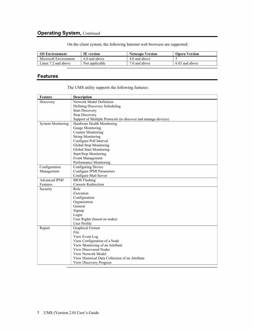
Operating System, Continued On the client system, the following Internet web browsers are supported:
OS Environment IE version Netscape Version Opera Version Microsoft Environment 6.0 and above 4.0 and above 5 Linux 7.2 and above Not applicable 7.0 and above 6.03 and above
Features
The UMS utility supports the following features:
Feature Description Discovery Network Model Definition
Defining Discovery Scheduling Start Discovery Stop Discovery Support of Multiple Protocols (to discover and manage devices)
System Monitoring Hardware Health Monitoring Gauge Monitoring Counter Monitoring String Monitoring Configure Poll Interval Global Stop Monitoring Global Start Monitoring Start/Stop Monitoring Event Management Performance Monitoring
Configuration Management
Configuring Device Configure IPMI Parameters Configure Mail Server
Advanced IPMI Features
BIOS Flashing Console Redirection
Security Role Execution Configuration Organization General Signup Login User Rights (based on nodes) User Profile
Report Graphical Format File View Event Log View Configuration of a Node View Monitoring of an Attribute View Discovered Nodes View Network Model View Historical Data Collection of an Attribute View Discovery Progress
Chapter One: Introduction 3
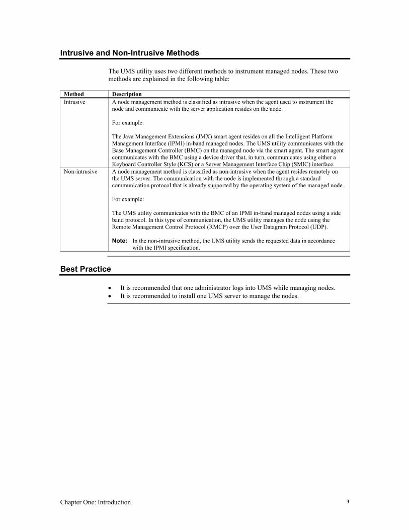
Intrusive and Non-Intrusive Methods The UMS utility uses two different methods to instrument managed nodes. These two methods are explained in the following table:
Method Description Intrusive A node management method is classified as intrusive when the agent used to instrument the
node and communicate with the server application resides on the node. For example: The Java Management Extensions (JMX) smart agent resides on all the Intelligent Platform Management Interface (IPMI) in-band managed nodes. The UMS utility communicates with the Base Management Controller (BMC) on the managed node via the smart agent. The smart agent communicates with the BMC using a device driver that, in turn, communicates using either a Keyboard Controller Style (KCS) or a Server Management Interface Chip (SMIC) interface.
Non-intrusive A node management method is classified as non-intrusive when the agent resides remotely on the UMS server. The communication with the node is implemented through a standard communication protocol that is already supported by the operating system of the managed node. For example: The UMS utility communicates with the BMC of an IPMI in-band managed nodes using a side band protocol. In this type of communication, the UMS utility manages the node using the Remote Management Control Protocol (RMCP) over the User Datagram Protocol (UDP). Note: In the non-intrusive method, the UMS utility sends the requested data in accordance
with the IPMI specification.
Best Practice
• It is recommended that one administrator logs into UMS while managing nodes. • It is recommended to install one UMS server to manage the nodes.

UMS (Version 2.0) User’s Guide 4
Chapter Two: Quick Installation 5
Chapter 2 Quick Installation
Before You Start
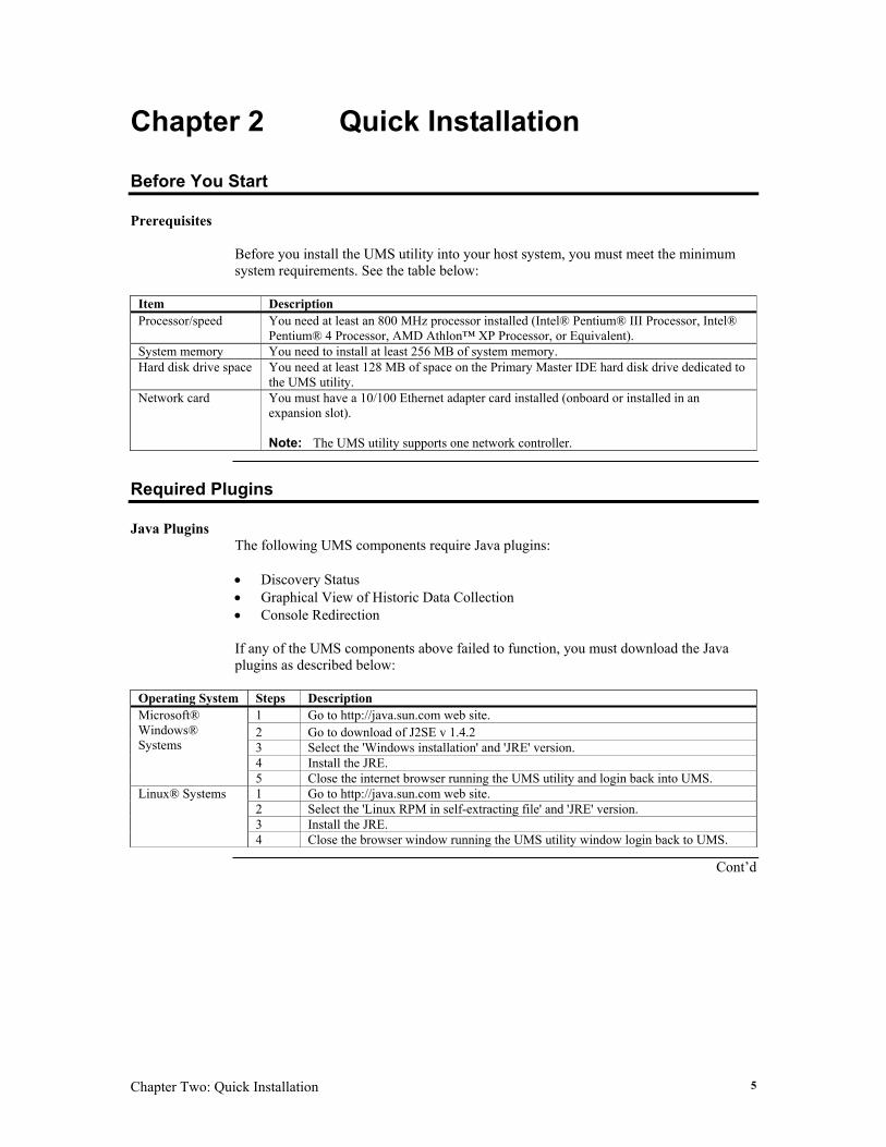
Prerequisites Before you install the UMS utility into your host system, you must meet the minimum system requirements. See the table below:
Item Description Processor/speed You need at least an 800 MHz processor installed (Intel® Pentium® III Processor, Intel®
Pentium® 4 Processor, AMD Athlon™ XP Processor, or Equivalent). System memory You need to install at least 256 MB of system memory. Hard disk drive space You need at least 128 MB of space on the Primary Master IDE hard disk drive dedicated to
the UMS utility. Network card You must have a 10/100 Ethernet adapter card installed (onboard or installed in an
expansion slot). Note: The UMS utility supports one network controller.
Required Plugins
Java Plugins
The following UMS components require Java plugins: • Discovery Status • Graphical View of Historic Data Collection • Console Redirection If any of the UMS components above failed to function, you must download the Java plugins as described below:
Operating System Steps Description 1 Go to http://java.sun.com web site. 2 Go to download of J2SE v 1.4.2 3 Select the 'Windows installation' and 'JRE' version. 4 Install the JRE.
Microsoft® Windows® Systems
5 Close the internet browser running the UMS utility and login back into UMS. 1 Go to http://java.sun.com web site. 2 Select the 'Linux RPM in self-extracting file' and 'JRE' version. 3 Install the JRE.
Linux® Systems
4 Close the browser window running the UMS utility window login back to UMS.
Cont’d
UMS (Version 2.0) User’s Guide 6
Required Plugins, Continued
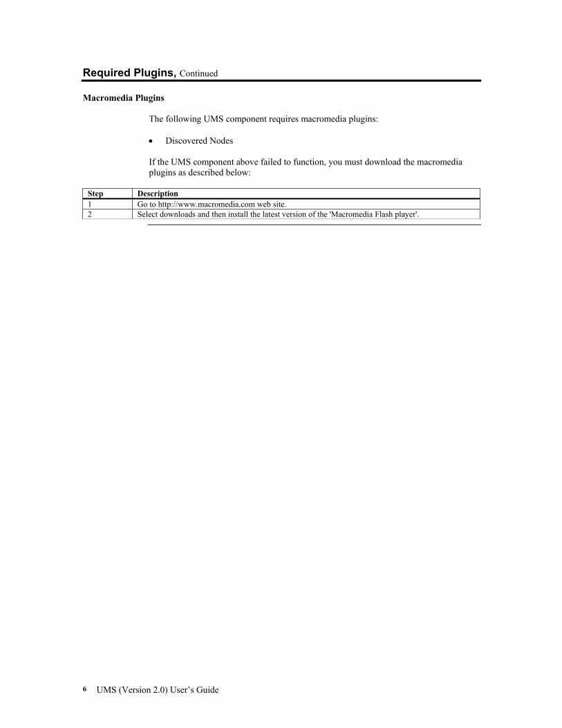
Macromedia Plugins The following UMS component requires macromedia plugins: • Discovered Nodes If the UMS component above failed to function, you must download the macromedia plugins as described below:
Step Description 1 Go to http://www.macromedia.com web site. 2 Select downloads and then install the latest version of the 'Macromedia Flash player'.
Chapter Two: Quick Installation 7
Installation
Installing Java Development Kit
Use the following steps to install the Java Development Kit into the host system.
Step Action 1 Insert the UMS CD into the host system. Double left click on the j2sdk-x_x_x_xx-windows-
i586.exe executable file to begin the Java Development Kit installation procedure.
Note: It is recommended that you install an Internet browser first, before installing the Java
Development Kit. By following this sequence, you ensure that all the necessary plug-ins required by the UMS utility are loaded.
Cont’d
UMS (Version 2.0) User’s Guide 8
Installation, Continued
Installing Java Development Kit, Continued
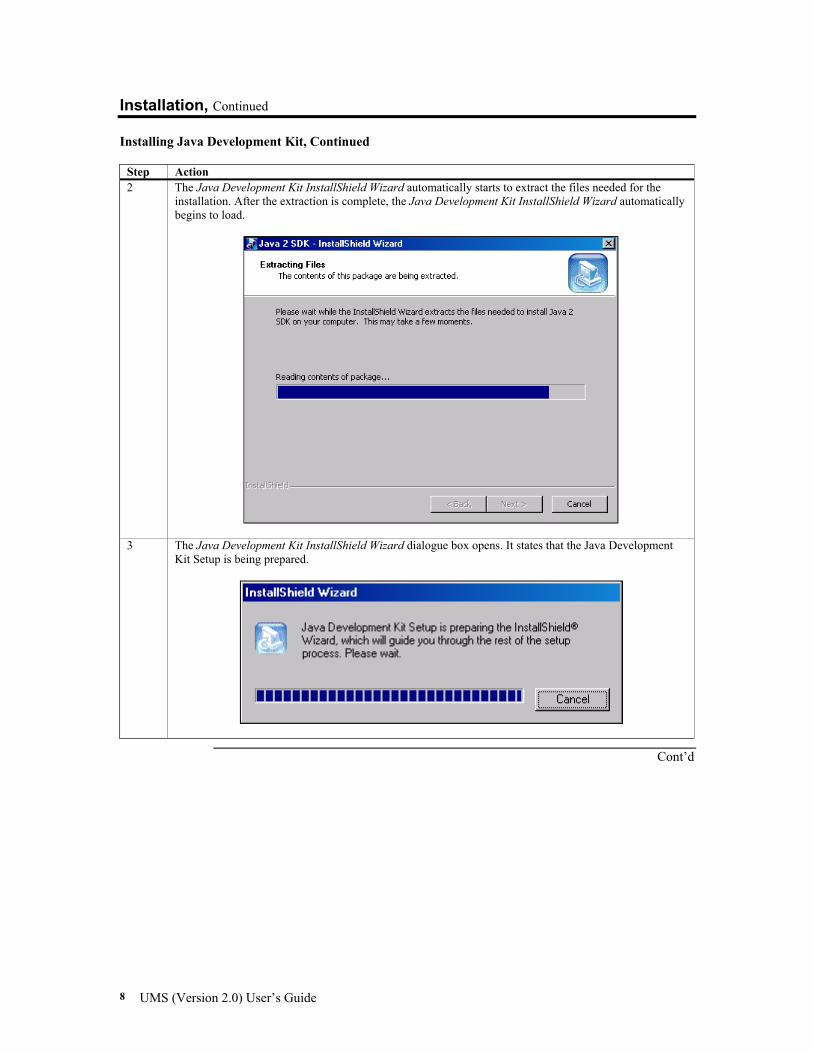
Step Action 2 The Java Development Kit InstallShield Wizard automatically starts to extract the files needed for the
installation. After the extraction is complete, the Java Development Kit InstallShield Wizard automatically begins to load.
3 The Java Development Kit InstallShield Wizard dialogue box opens. It states that the Java Development Kit Setup is being prepared.
Cont’d
Chapter Two: Quick Installation 9
Installation, Continued
Installing Java Development Kit, Continued
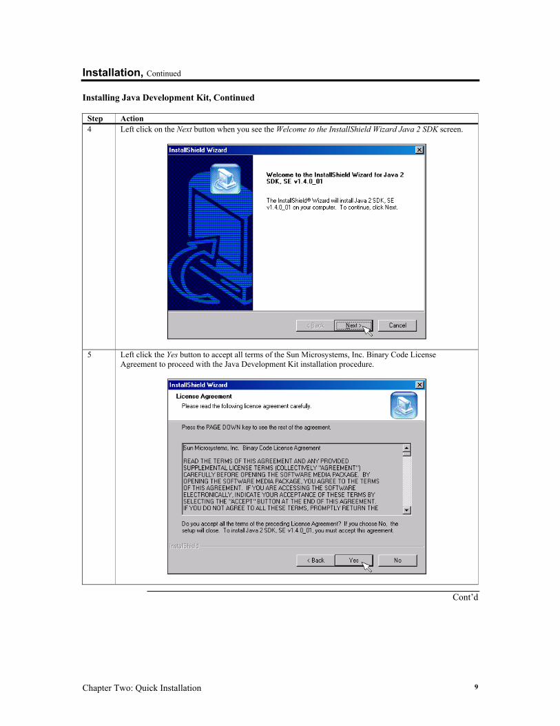
Step Action 4 Left click on the Next button when you see the Welcome to the InstallShield Wizard Java 2 SDK screen.
5 Left click the Yes button to accept all terms of the Sun Microsystems, Inc. Binary Code License Agreement to proceed with the Java Development Kit installation procedure.
Cont’d
UMS (Version 2.0) User’s Guide 10
Installation, Continued
Installing Java Development Kit, Continued
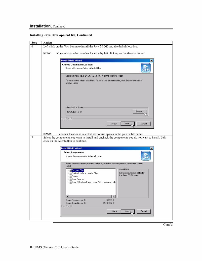
Step Action 6 Left click on the Next button to install the Java 2 SDK into the default location.
Note: You can also select another location by left clicking on the Browse button.
Note: If another location is selected, do not use spaces in the path or file name.
7 Select the components you want to install and uncheck the components you do not want to install. Left click on the Next button to continue.
Cont’d
Chapter Two: Quick Installation 11
Installation, Continued
Installing Java Development Kit, Continued
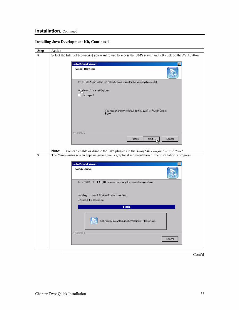
Step Action 8 Select the Internet browser(s) you want to use to access the UMS server and left click on the Next button.
Note: You can enable or disable the Java plug-ins in the Java(TM) Plug-in Control Panel.
9 The Setup Status screen appears giving you a graphical representation of the installation’s progress.
Cont’d
UMS (Version 2.0) User’s Guide 12
Installation, Continued
Installing Java Development Kit, Continued
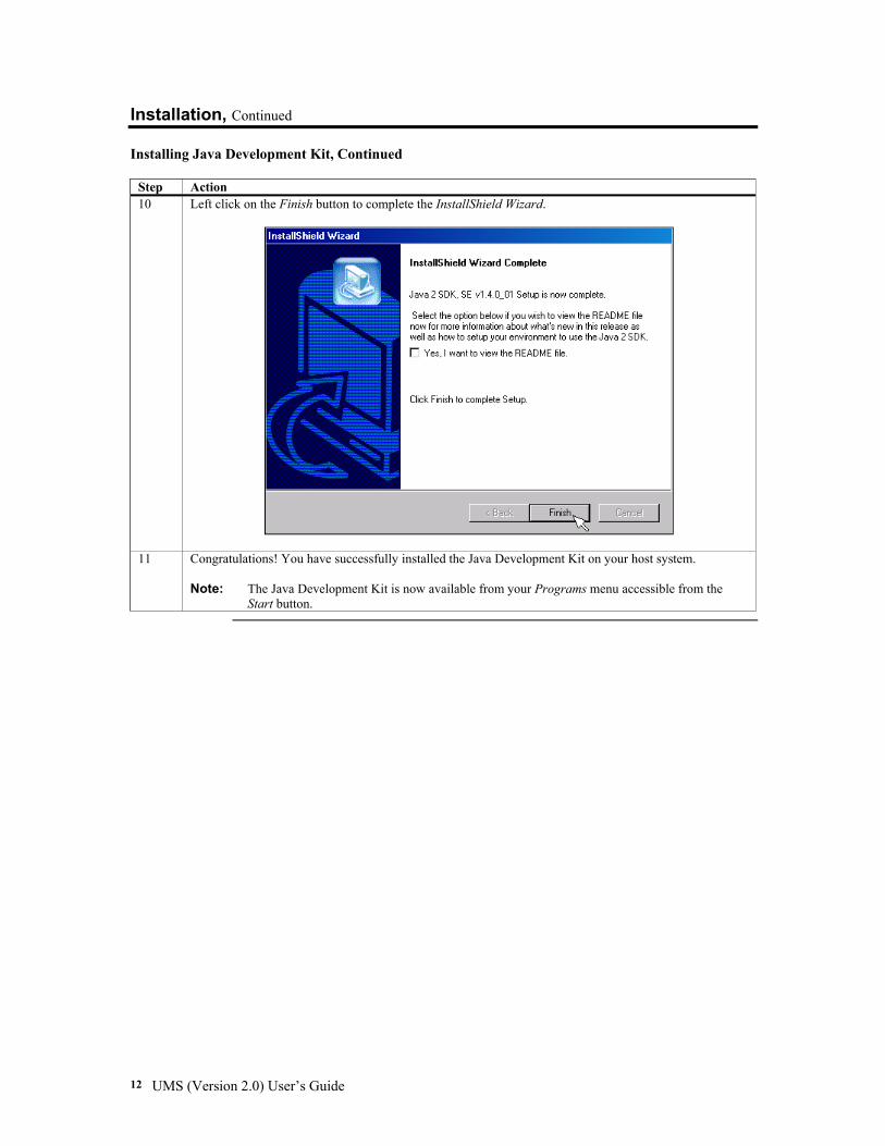
Step Action 10 Left click on the Finish button to complete the InstallShield Wizard.
11 Congratulations! You have successfully installed the Java Development Kit on your host system. Note: The Java Development Kit is now available from your Programs menu accessible from the
Start button.
Chapter Two: Quick Installation 13
Installation, Continued
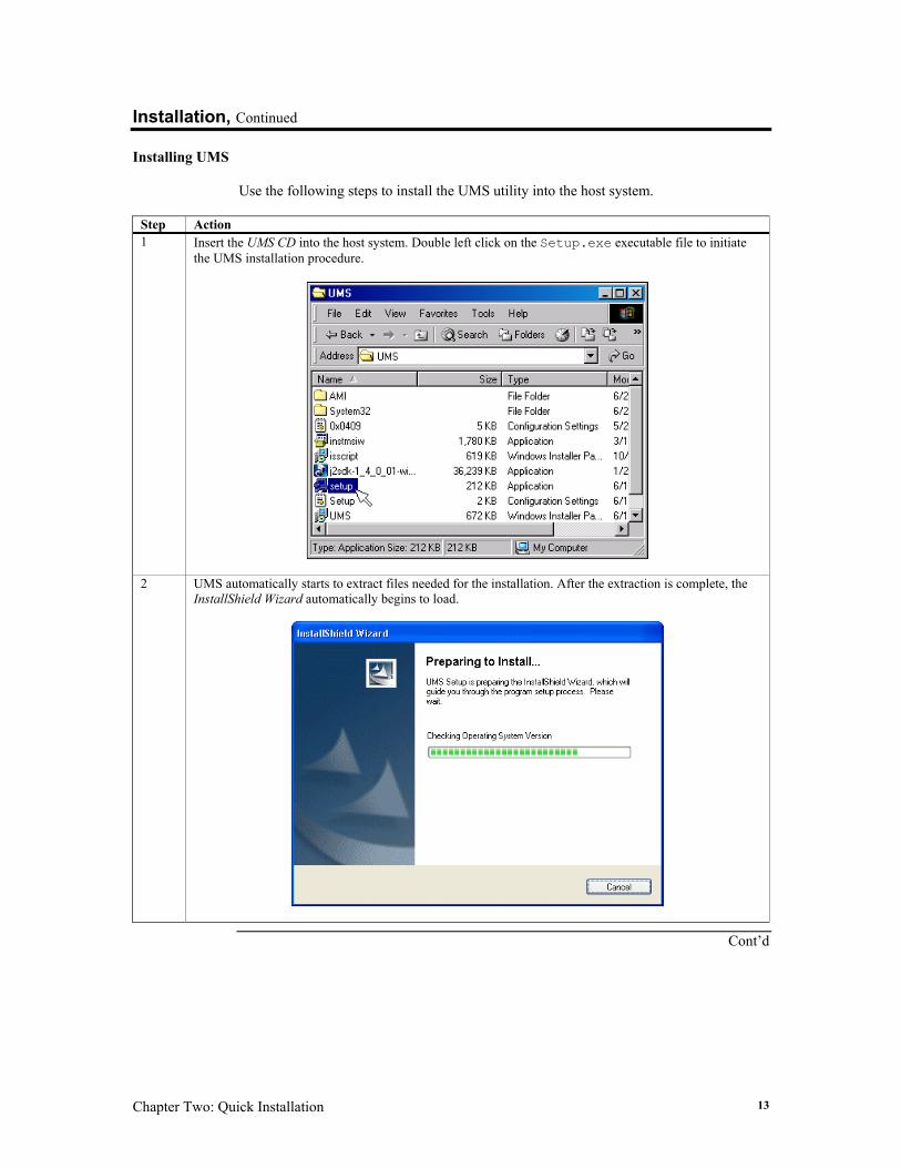
Installing UMS Use the following steps to install the UMS utility into the host system.
Step Action 1 Insert the UMS CD into the host system. Double left click on the Setup.exe executable file to initiate
the UMS installation procedure.
2 UMS automatically starts to extract files needed for the installation. After the extraction is complete, the InstallShield Wizard automatically begins to load.
Cont’d
UMS (Version 2.0) User’s Guide 14
Installation, Continued
Installing UMS, Continued
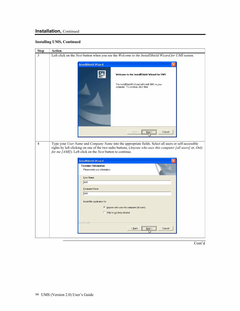
Step Action 3 Left click on the Next button when you see the Welcome to the InstallShield Wizard for UMS screen.
4 Type your User Name and Company Name into the appropriate fields. Select all users or self-accessible rights by left clicking on one of the two radio buttons, (Anyone who uses this computer [all users] or, Only for me [AMI]). Left click on the Next button to continue.
Cont’d
Chapter Two: Quick Installation 15
Installation, Continued
Installing UMS, Continued
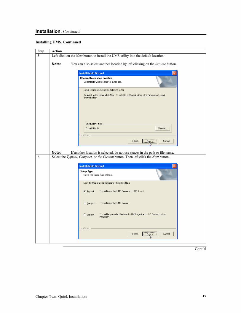
Step Action 5 Left click on the Next button to install the UMS utility into the default location.
Note: You can also select another location by left clicking on the Browse button.
Note: If another location is selected, do not use spaces in the path or file name.
6 Select the Typical, Compact, or the Custom button. Then left click the Next button.
Cont’d
UMS (Version 2.0) User’s Guide 16
Installation, Continued
Installing UMS, Continued
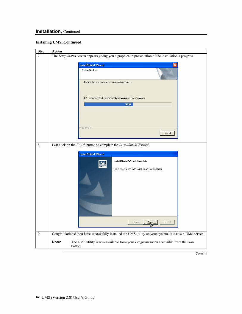
Step Action 7 The Setup Status screen appears giving you a graphical representation of the installation’s progress.
8 Left click on the Finish button to complete the InstallShield Wizard.
9 Congratulations! You have successfully installed the UMS utility on your system. It is now a UMS server. Note: The UMS utility is now available from your Programs menu accessible from the Start
button.
Cont’d
Chapter Two: Quick Installation 17
Installation, Continued
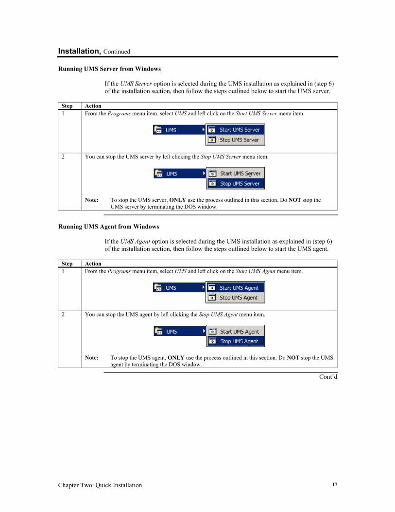
Running UMS Server from Windows If the UMS Server option is selected during the UMS installation as explained in (step 6) of the installation section, then follow the steps outlined below to start the UMS server.
Step Action 1 From the Programs menu item, select UMS and left click on the Start UMS Server menu item.
2 You can stop the UMS server by left clicking the Stop UMS Server menu item.
Note: To stop the UMS server, ONLY use the process outlined in this section. Do NOT stop the
UMS server by terminating the DOS window.
Running UMS Agent from Windows
If the UMS Agent option is selected during the UMS installation as explained in (step 6) of the installation section, then follow the steps outlined below to start the UMS agent.
Step Action 1 From the Programs menu item, select UMS and left click on the Start UMS Agent menu item.
2 You can stop the UMS agent by left clicking the Stop UMS Agent menu item.
Note: To stop the UMS agent, ONLY use the process outlined in this section. Do NOT stop the UMS
agent by terminating the DOS window.
Cont’d
UMS (Version 2.0) User’s Guide 18
Installation, Continued
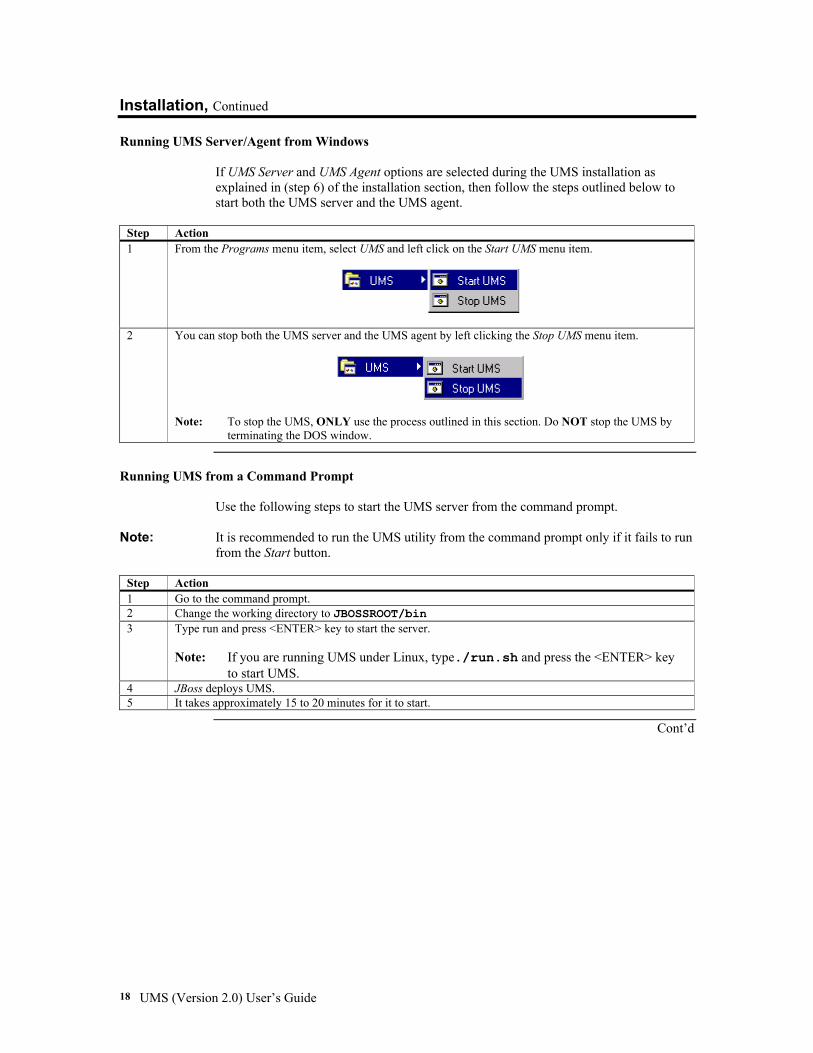
Running UMS Server/Agent from Windows If UMS Server and UMS Agent options are selected during the UMS installation as explained in (step 6) of the installation section, then follow the steps outlined below to start both the UMS server and the UMS agent.
Step Action 1 From the Programs menu item, select UMS and left click on the Start UMS menu item.
2 You can stop both the UMS server and the UMS agent by left clicking the Stop UMS menu item.
Note: To stop the UMS, ONLY use the process outlined in this section. Do NOT stop the UMS by
terminating the DOS window.
Running UMS from a Command Prompt
Use the following steps to start the UMS server from the command prompt.
Note: It is recommended to run the UMS utility from the command prompt only if it fails to run from the Start button.
Step Action 1 Go to the command prompt. 2 Change the working directory to JBOSSROOT/bin 3 Type run and press <ENTER> key to start the server.
Note: If you are running UMS under Linux, type./run.sh and press the <ENTER> key
to start UMS. 4 JBoss deploys UMS. 5 It takes approximately 15 to 20 minutes for it to start.
Cont’d
Chapter Two: Quick Installation 19
Installation, Continued
Running UMS from a Command Prompt, Continued
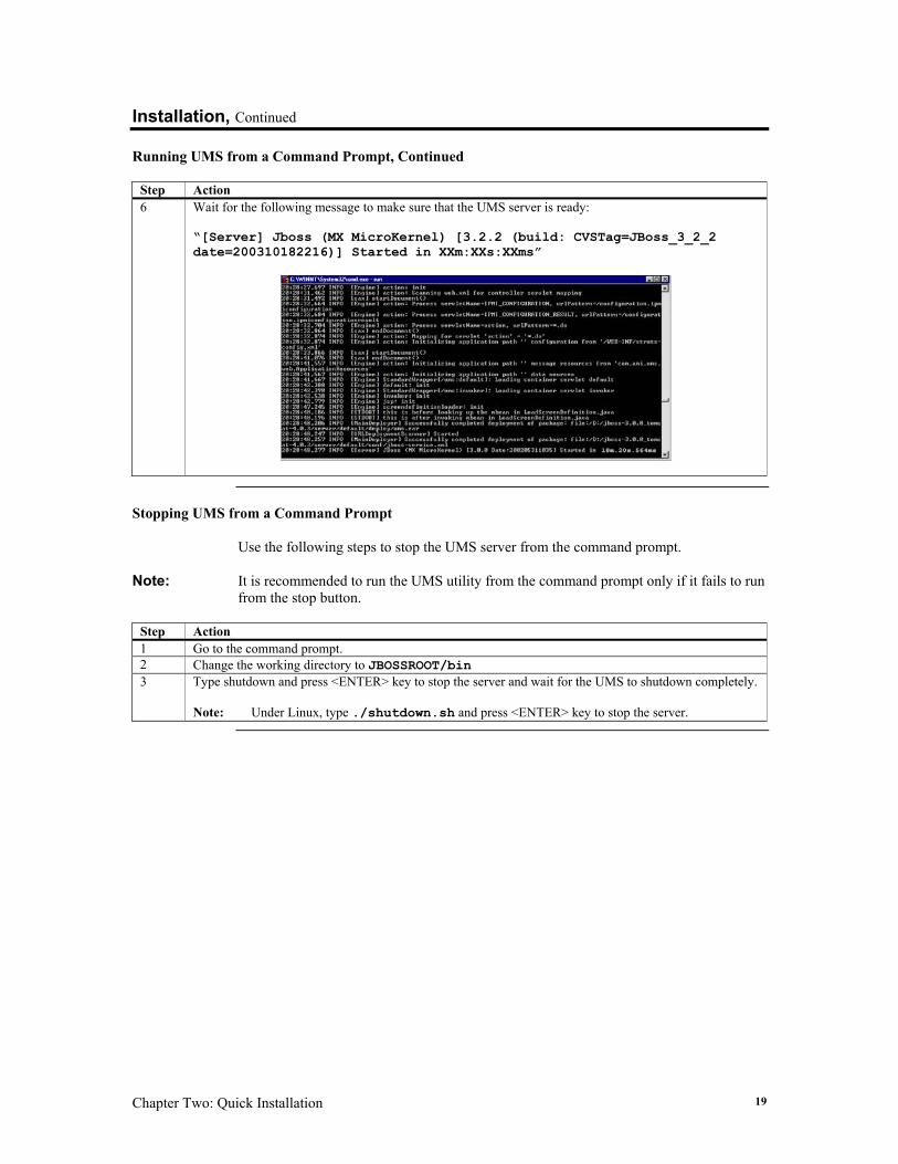
Step Action 6 Wait for the following message to make sure that the UMS server is ready:
“[Server] Jboss (MX MicroKernel) [3.2.2 (build: CVSTag=JBoss_3_2_2 date=200310182216)] Started in XXm:XXs:XXms”
Stopping UMS from a Command Prompt
Use the following steps to stop the UMS server from the command prompt.
Note: It is recommended to run the UMS utility from the command prompt only if it fails to run from the stop button.
Step Action 1 Go to the command prompt. 2 Change the working directory to JBOSSROOT/bin 3 Type shutdown and press <ENTER> key to stop the server and wait for the UMS to shutdown completely.
Note: Under Linux, type ./shutdown.sh and press <ENTER> key to stop the server.
UMS (Version 2.0) User’s Guide 20
Connecting Use the following steps to connect to your UMS server.
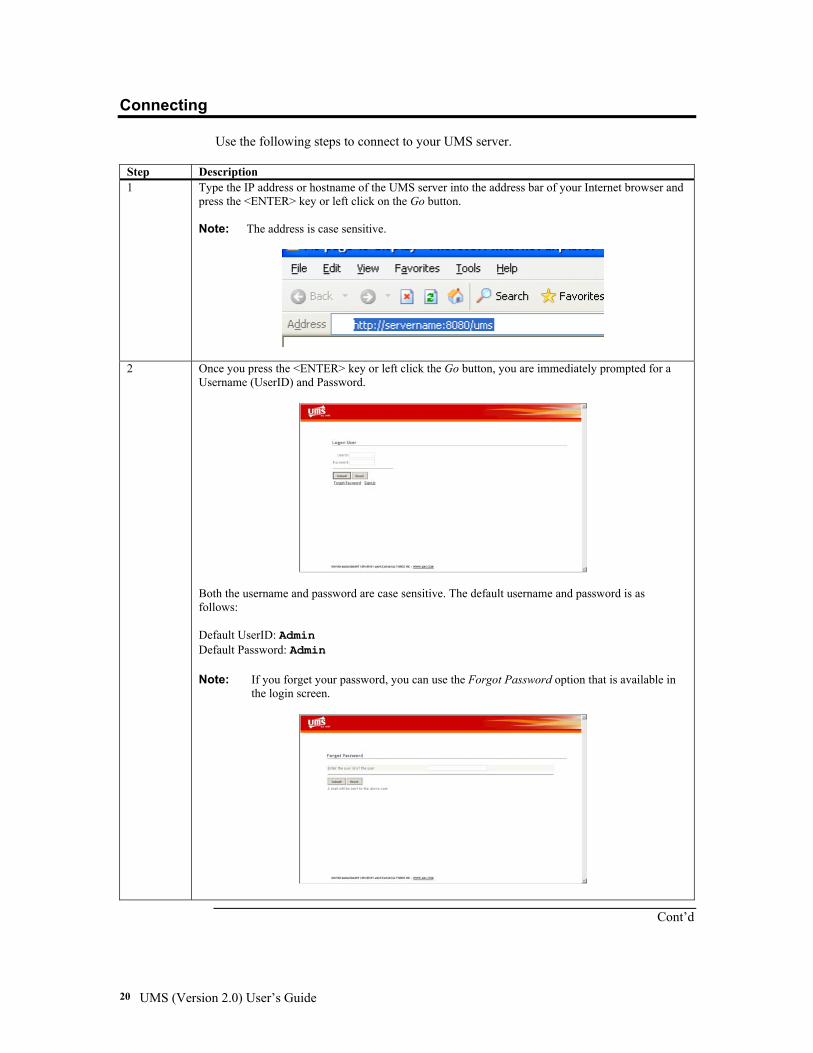
Step Description 1 Type the IP address or hostname of the UMS server into the address bar of your Internet browser and
press the <ENTER> key or left click on the Go button. Note: The address is case sensitive.
2 Once you press the <ENTER> key or left click the Go button, you are immediately prompted for a Username (UserID) and Password.
Both the username and password are case sensitive. The default username and password is as follows: Default UserID: Admin Default Password: Admin Note: If you forget your password, you can use the Forgot Password option that is available in
the login screen.
Cont’d
Chapter Two: Quick Installation 21
Connecting, Continued
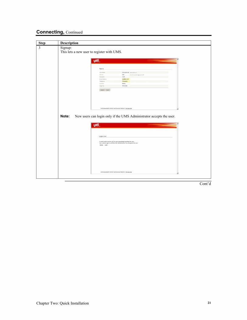
Step Description 3 Signup:
This lets a new user to register with UMS.
Note: New users can login only if the UMS Administrator accepts the user.
Cont’d
UMS (Version 2.0) User’s Guide 22
Connecting, Continued
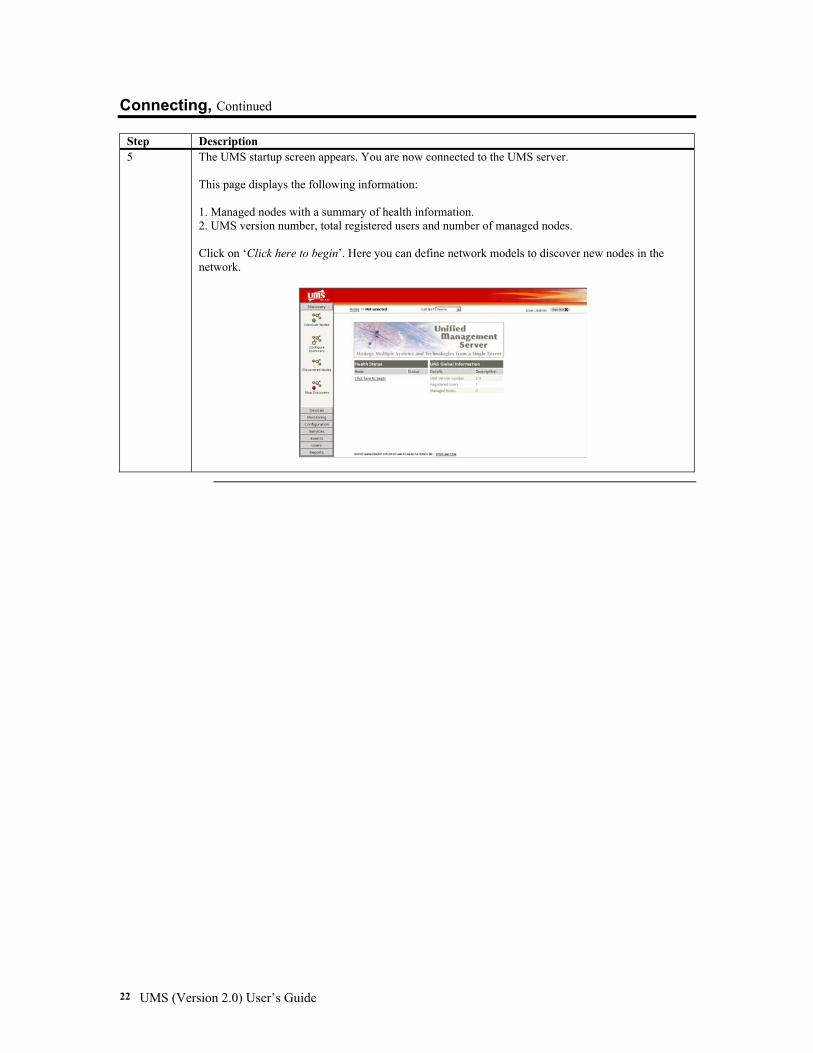
Step Description 5 The UMS startup screen appears. You are now connected to the UMS server.
This page displays the following information: 1. Managed nodes with a summary of health information. 2. UMS version number, total registered users and number of managed nodes. Click on ‘Click here to begin’. Here you can define network models to discover new nodes in the network.
Chapter Two: Quick Installation 23
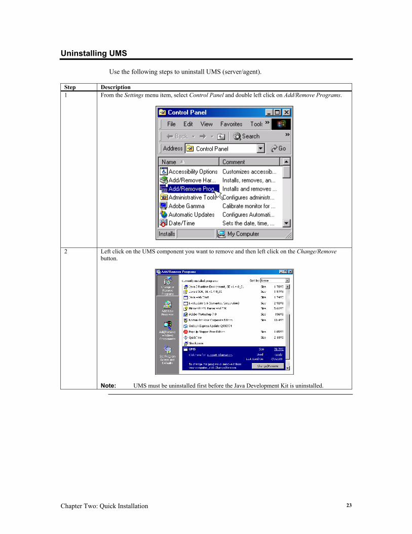
Uninstalling UMS Use the following steps to uninstall UMS (server/agent).
Step Description 1 From the Settings menu item, select Control Panel and double left click on Add/Remove Programs.
2 Left click on the UMS component you want to remove and then left click on the Change/Remove button.
Note: UMS must be uninstalled first before the Java Development Kit is uninstalled.

UMS (Version 2.0) User’s Guide 24
Chapter Three: Configuring Your UMS Server 25
Chapter 3 Configuring Your UMS Server
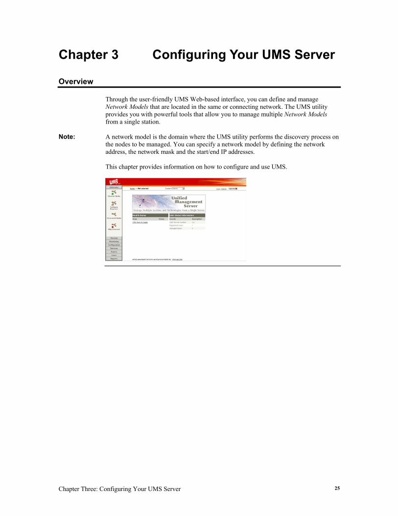
Overview Through the user-friendly UMS Web-based interface, you can define and manage Network Models that are located in the same or connecting network. The UMS utility provides you with powerful tools that allow you to manage multiple Network Models from a single station.
Note: A network model is the domain where the UMS utility performs the discovery process on the nodes to be managed. You can specify a network model by defining the network address, the network mask and the start/end IP addresses. This chapter provides information on how to configure and use UMS.
UMS (Version 2.0) User’s Guide 26
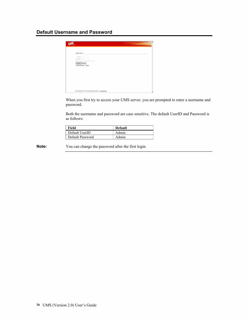
Default Username and Password
When you first try to access your UMS server, you are prompted to enter a username and password. Both the username and password are case sensitive. The default UserID and Password is as follows:
Field Default Default UserID Admin Default Password Admin
Note: You can change the password after the first login.
Chapter Three: Configuring Your UMS Server 27
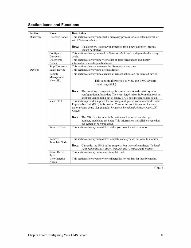
Section Icons and Functions
Section Name Description Discover Nodes This section allows you to start a discovery process for a selected network or
set of Network Models. Note: If a discovery is already in progress, then a new discovery process
cannot be started. Configure Discovery
This section allows you to add a Network Model and configure the discovery cycle.
Discovered Nodes
This section allows you to view a list of discovered nodes and display information on each specified node.
Discovery
Stop Discovery This section allows you to stop the discovery at any time. Select Device This section allows you to select a device. Remote Management
This section allows you to execute all remote actions on the selected device.
View SEL This section allows you to view the BMC System Event Log (SEL).
Note: The event log is a repository for system events and certain system
configuration information. The event log displays information such as attribute values going out of range, BIOS post messages, and so on.
View FRU This section provides support for accessing multiple sets of non-volatile Field Replaceable Unit (FRU) information. You can access information for each major system board (for example: Processor board and Memory board, I/O board). Note: The FRU data includes information such as serial number, part
number, model and asset tag. This information is available even when the system is powered down.
Remove Node This section allows you to delete nodes you do not want to monitor.
Remove Template Node
This section allows you to delete template nodes you do not want to monitor. Note: Currently, the UMS utility supports four types of templates: (In-band
Root Template, AMI Root Template, Root Template and Switch). Select Device Type
This section allows you to select template node.
Devices
View Inactive Nodes
This section allows you to view collected historical data for inactive nodes.
Cont’d
UMS (Version 2.0) User’s Guide 28
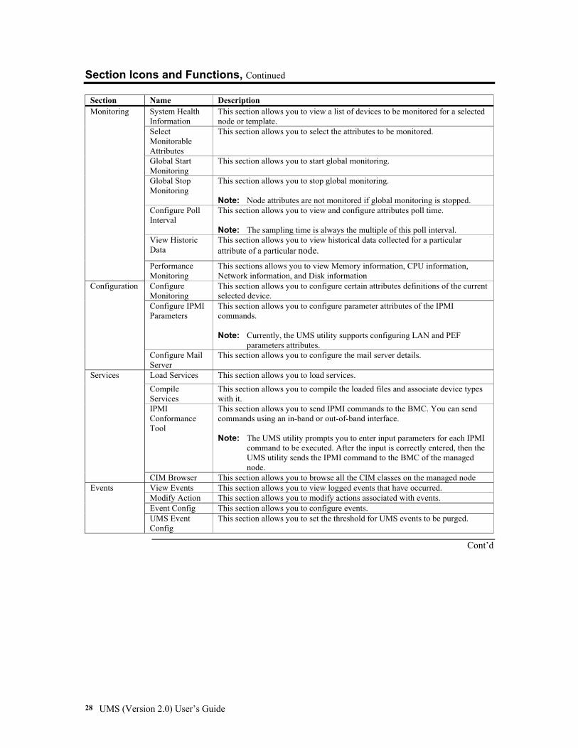
Section Icons and Functions, Continued
Section Name Description System Health Information
This section allows you to view a list of devices to be monitored for a selected node or template.
Select Monitorable Attributes
This section allows you to select the attributes to be monitored.
Global Start Monitoring
This section allows you to start global monitoring.
Global Stop Monitoring
This section allows you to stop global monitoring. Note: Node attributes are not monitored if global monitoring is stopped.
Configure Poll Interval
This section allows you to view and configure attributes poll time. Note: The sampling time is always the multiple of this poll interval.
View Historic Data
This section allows you to view historical data collected for a particular attribute of a particular node.
Monitoring
Performance Monitoring
This sections allows you to view Memory information, CPU information, Network information, and Disk information
Configure Monitoring
This section allows you to configure certain attributes definitions of the current selected device.
Configure IPMI Parameters
This section allows you to configure parameter attributes of the IPMI commands. Note: Currently, the UMS utility supports configuring LAN and PEF
parameters attributes.
Configuration
Configure Mail Server
This section allows you to configure the mail server details.
Load Services This section allows you to load services. Compile Services
This section allows you to compile the loaded files and associate device types with it.
IPMI Conformance Tool
This section allows you to send IPMI commands to the BMC. You can send commands using an in-band or out-of-band interface. Note: The UMS utility prompts you to enter input parameters for each IPMI
command to be executed. After the input is correctly entered, then the UMS utility sends the IPMI command to the BMC of the managed node.
Services
CIM Browser This section allows you to browse all the CIM classes on the managed node View Events This section allows you to view logged events that have occurred. Modify Action This section allows you to modify actions associated with events. Event Config This section allows you to configure events.
Events
UMS Event Config
This section allows you to set the threshold for UMS events to be purged.
Cont’d
Chapter Three: Configuring Your UMS Server 29
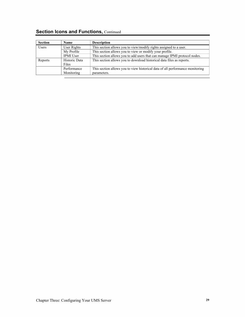
Section Icons and Functions, Continued
Section Name Description User Rights This section allows you to view/modify rights assigned to a user. My Profile This section allows you to view or modify your profile.
Users
IPMI User This section allows you to add users that can manage IPMI protocol nodes. Reports Historic Data
Files This section allows you to download historical data files as reports.
Performance Monitoring
This section allows you to view historical data of all performance monitoring parameters.
UMS (Version 2.0) User’s Guide 30
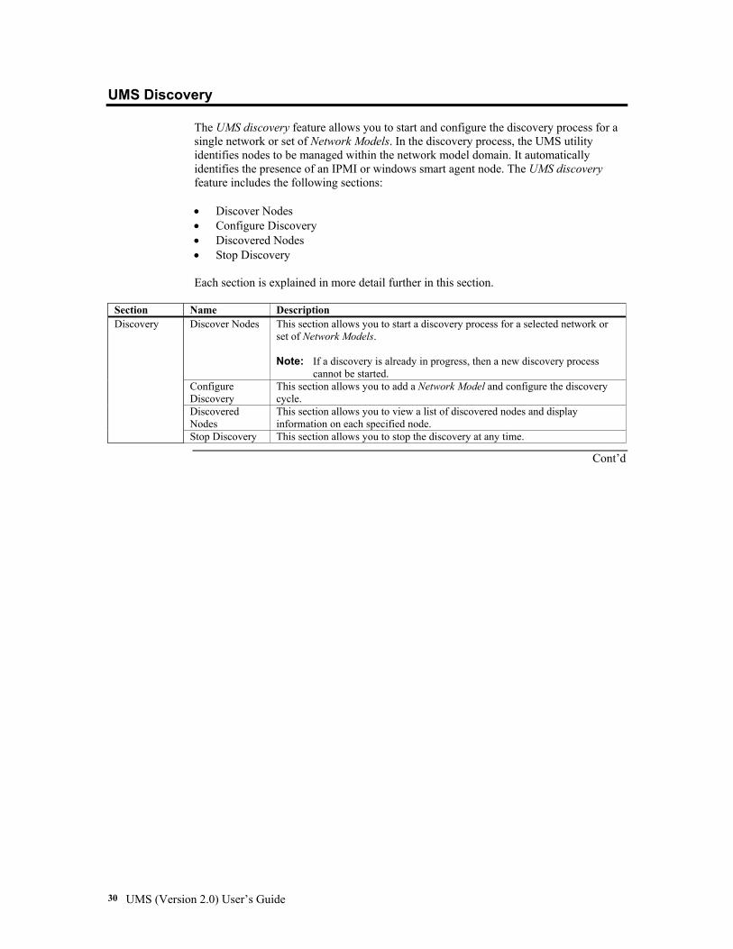
UMS Discovery The UMS discovery feature allows you to start and configure the discovery process for a single network or set of Network Models. In the discovery process, the UMS utility identifies nodes to be managed within the network model domain. It automatically identifies the presence of an IPMI or windows smart agent node. The UMS discovery feature includes the following sections: • Discover Nodes • Configure Discovery • Discovered Nodes • Stop Discovery Each section is explained in more detail further in this section.
Section Name Description
Discover Nodes This section allows you to start a discovery process for a selected network or set of Network Models. Note: If a discovery is already in progress, then a new discovery process
cannot be started. Configure Discovery
This section allows you to add a Network Model and configure the discovery cycle.
Discovered Nodes
This section allows you to view a list of discovered nodes and display information on each specified node.
Discovery
Stop Discovery This section allows you to stop the discovery at any time.
Cont’d
Chapter Three: Configuring Your UMS Server 31
UMS Discovery, Continued
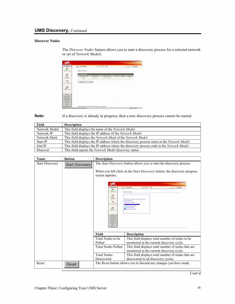
Discover Nodes The Discover Nodes feature allows you to start a discovery process for a selected network or set of Network Models.
Note: If a discovery is already in progress, then a new discovery process cannot be started.
Field Description Network Model This field displays the name of the Network Model. Network IP This field displays the IP address of the Network Model. Network Mask This field displays the Network Mask of the Network Model. Start IP This field displays the IP address where the discovery process starts in the Network Model. End IP This field displays the IP address where the discovery process ends in the Network Model. Discover This field reports the Network Model discovery status.
Name Button Description
The Start Discovery button allows you to start the discovery process. When you left click on the Start Discovery button, the discovery progress screen appears:
Field Description Total Nodes to be Polled
This field displays total number of nodes to be monitored in the current discovery cycle.
Total Nodes Polled This field displays total number of nodes that are monitored in the current discovery cycle.
Start Discovery
Total Nodes Discovered
This field displays total number of nodes that are discovered in all discovery cycles.
Reset
The Reset button allows you to discard any changes you have made.
Cont’d
UMS (Version 2.0) User’s Guide 32
UMS Discovery, Continued
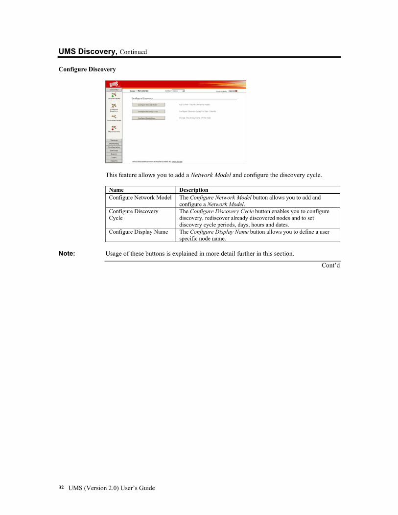
Configure Discovery
This feature allows you to add a Network Model and configure the discovery cycle.
Name Description Configure Network Model The Configure Network Model button allows you to add and
configure a Network Model. Configure Discovery Cycle
The Configure Discovery Cycle button enables you to configure discovery, rediscover already discovered nodes and to set discovery cycle periods, days, hours and dates.
Configure Display Name The Configure Display Name button allows you to define a user specific node name.
Note: Usage of these buttons is explained in more detail further in this section.
Cont’d
Chapter Three: Configuring Your UMS Server 33
UMS Discovery, Continued
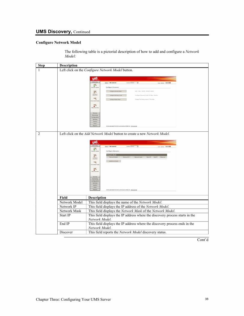
Configure Network Model The following table is a pictorial description of how to add and configure a Network Model:
Step Description 1 Left click on the Configure Network Model button.
Left click on the Add Network Model button to create a new Network Model.
Field Description Network Model This field displays the name of the Network Model. Network IP This field displays the IP address of the Network Model. Network Mask This field displays the Network Mask of the Network Model. Start IP This field displays the IP address where the discovery process starts in the
Network Model. End IP This field displays the IP address where the discovery process ends in the
Network Model.
2
Discover This field reports the Network Model discovery status.
Cont’d
UMS (Version 2.0) User’s Guide 34
UMS Discovery, Continued
Configure Network Model, Continued
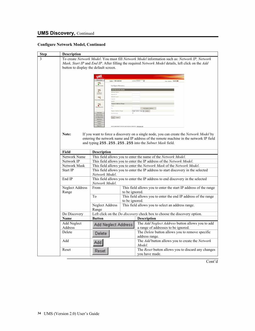
Step Description To create Network Model. You must fill Network Model information such as: Network IP, Network Mask, Start IP and End IP. After filling the required Network Model details, left click on the Add button to display the default screen.
Note: If you want to force a discovery on a single node, you can create the Network Model by
entering the network name and IP address of the remote machine in the network IP field and typing 255.255.255.255 into the Subnet Mask field.
Field Description Network Name This field allows you to enter the name of the Network Model. Network IP This field allows you to enter the IP address of the Network Model. Network Mask This field allows you to enter the Network Mask of the Network Model. Start IP This field allows you to enter the IP address to start discovery in the selected
Network Model. End IP This field allows you to enter the IP address to end discovery in the selected
Network Model. From This field allows you to enter the start IP address of the range
to be ignored. To This field allows you to enter the end IP address of the range
to be ignored.
Neglect Address Range
Neglect Address Range
This field allows you to select an address range.
Do Discovery Left click on the Do discovery check box to choose the discovery option. Name Button Description Add Neglect Address
The Add Neglect Address button allows you to add a range of addresses to be ignored.
Delete
The Delete button allows you to remove specific address range.
Add
The Add button allows you to create the Network Model.
3
Reset
The Reset button allows you to discard any changes you have made.
Cont’d
Chapter Three: Configuring Your UMS Server 35
UMS Discovery, Continued
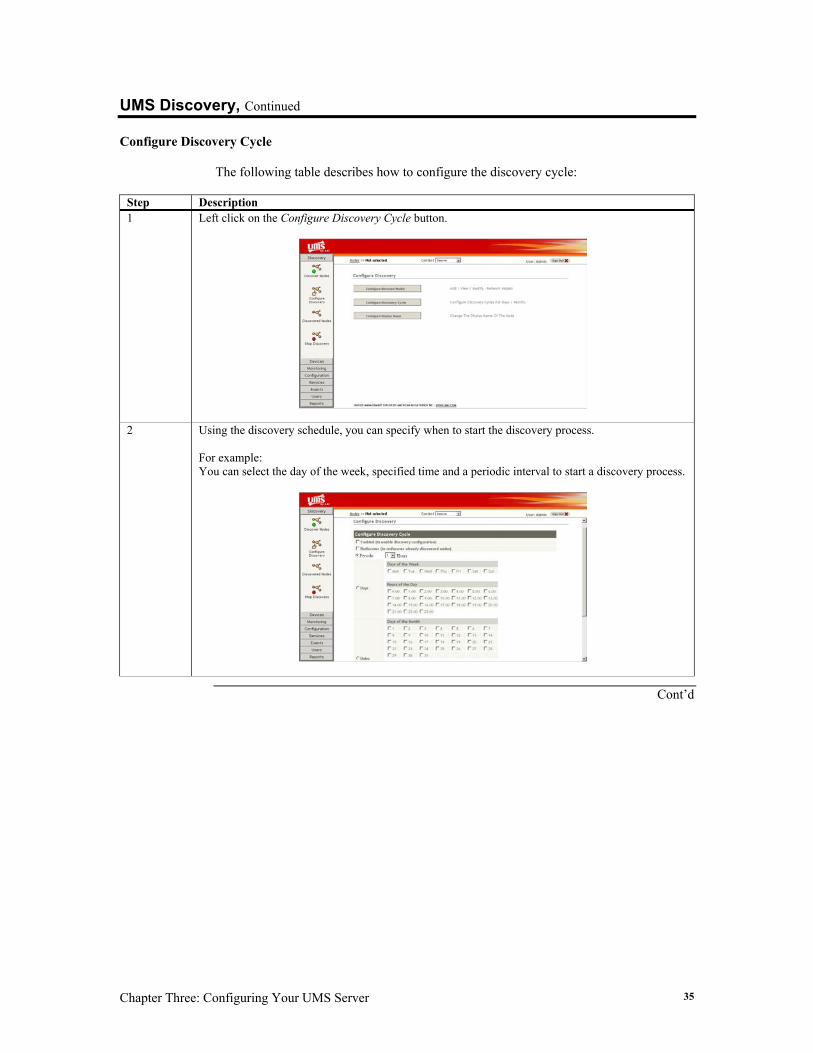
Configure Discovery Cycle The following table describes how to configure the discovery cycle:
Step Description 1 Left click on the Configure Discovery Cycle button.
2 Using the discovery schedule, you can specify when to start the discovery process. For example: You can select the day of the week, specified time and a periodic interval to start a discovery process.
Cont’d
UMS (Version 2.0) User’s Guide 36
UMS Discovery, Continued
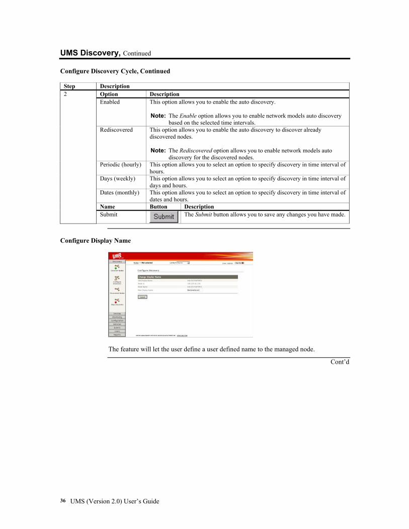
Configure Discovery Cycle, Continued
Step Description Option Description Enabled This option allows you to enable the auto discovery.
Note: The Enable option allows you to enable network models auto discovery
based on the selected time intervals. Rediscovered This option allows you to enable the auto discovery to discover already
discovered nodes. Note: The Rediscovered option allows you to enable network models auto
discovery for the discovered nodes. Periodic (hourly) This option allows you to select an option to specify discovery in time interval of
hours. Days (weekly) This option allows you to select an option to specify discovery in time interval of
days and hours. Dates (monthly) This option allows you to select an option to specify discovery in time interval of
dates and hours. Name Button Description
2
Submit The Submit button allows you to save any changes you have made.
Configure Display Name
The feature will let the user define a user defined name to the managed node.
Cont’d
Chapter Three: Configuring Your UMS Server 37
UMS Discovery, Continued
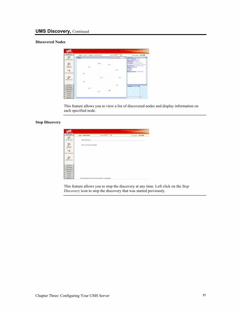
Discovered Nodes
This feature allows you to view a list of discovered nodes and display information on each specified node.
Stop Discovery
This feature allows you to stop the discovery at any time. Left click on the Stop Discovery icon to stop the discovery that was started previously.
UMS (Version 2.0) User’s Guide 38
UMS Device The UMS Device feature allows you to set any of the managed devices to be the current one. The UMS Device feature includes the following sections:
• Select Device • Remote Management • View SEL • View FRU • Remove Node • Remove Template Node • Select Device Type • View Inactive nodes Each section is explained in more detail further in this section.
Section Name Description Select Device This section allows you to select a device. Method Invocation
This section allows you to invoke a method on a selected device remotely.
View SEL This section allows you to view the BMC event log. Note: The event log is a repository for system events and certain system
configuration information. The event log displays information such as attribute values going out of range, BIOS post messages, and so on.
View FRU This section provides support for accessing multiple sets of non-volatile FRU information. You can access information for each major system board (for example: Processor board and Memory board, I/O board). Note: The FRU data includes information such as serial number, part
number, model, and asset tag. This information is available even when the system is powered down.
Remove Node This section allows you to delete nodes that you do not want to monitor from the managed group.
Remove Template Node
This section allows you to delete template nodes that you do not want to monitor from the managed group. Note: Currently, the UMS utility supports four types of templates: (In-band
Root Template, AMI Root Template, Root Template and Switch). Select Device Type
This section allows you to select a template node.
Devices
View Inactive Nodes
This section allows you to view collected historical data for inactive nodes.
Cont’d
Chapter Three: Configuring Your UMS Server 39
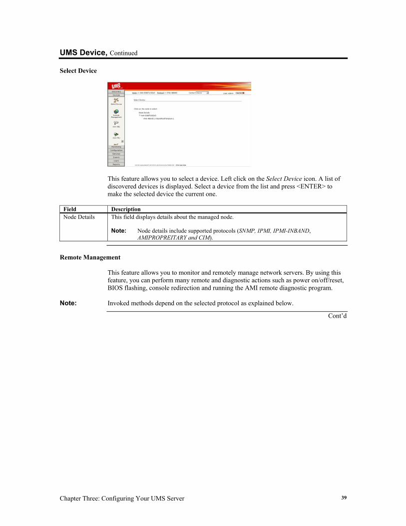
UMS Device, Continued Select Device
This feature allows you to select a device. Left click on the Select Device icon. A list of discovered devices is displayed. Select a device from the list and press <ENTER> to make the selected device the current one.
Field Description Node Details This field displays details about the managed node.
Note: Node details include supported protocols (SNMP, IPMI, IPMI-INBAND,
AMIPROPREITARY and CIM).
Remote Management
This feature allows you to monitor and remotely manage network servers. By using this feature, you can perform many remote and diagnostic actions such as power on/off/reset, BIOS flashing, console redirection and running the AMI remote diagnostic program.
Note: Invoked methods depend on the selected protocol as explained below.
Cont’d
UMS (Version 2.0) User’s Guide 40
UMS Device, Continued
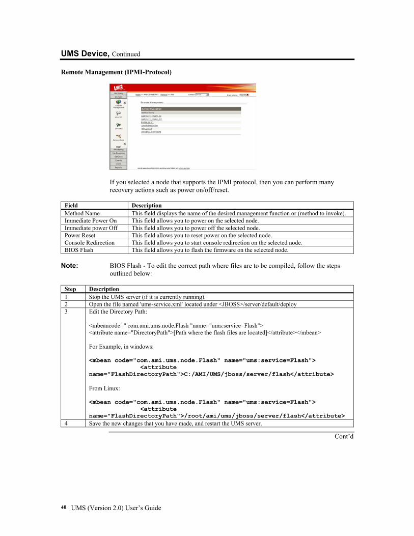
Remote Management (IPMI-Protocol)
If you selected a node that supports the IPMI protocol, then you can perform many recovery actions such as power on/off/reset.
Field Description Method Name This field displays the name of the desired management function or (method to invoke). Immediate Power On This field allows you to power on the selected node. Immediate power Off This field allows you to power off the selected node. Power Reset This field allows you to reset power on the selected node. Console Redirection This field allows you to start console redirection on the selected node. BIOS Flash This field allows you to flash the firmware on the selected node.
Note: BIOS Flash - To edit the correct path where files are to be compiled, follow the steps
outlined below:
Step Description 1 Stop the UMS server (if it is currently running). 2 Open the file named 'ums-service.xml' located under <JBOSS>/server/default/deploy 3 Edit the Directory Path:
<mbeancode=" com.ami.ums.node.Flash "name="ums:service=Flash"> <attribute name="DirectoryPath">[Path where the flash files are located]</attribute></mbean> For Example, in windows: <mbean code="com.ami.ums.node.Flash" name="ums:service=Flash"> <attribute name="FlashDirectoryPath">C:/AMI/UMS/jboss/server/flash</attribute> From Linux: <mbean code="com.ami.ums.node.Flash" name="ums:service=Flash"> <attribute name="FlashDirectoryPath">/root/ami/ums/jboss/server/flash</attribute>
4 Save the new changes that you have made, and restart the UMS server.
Cont’d
Chapter Three: Configuring Your UMS Server 41
UMS Device, Continued
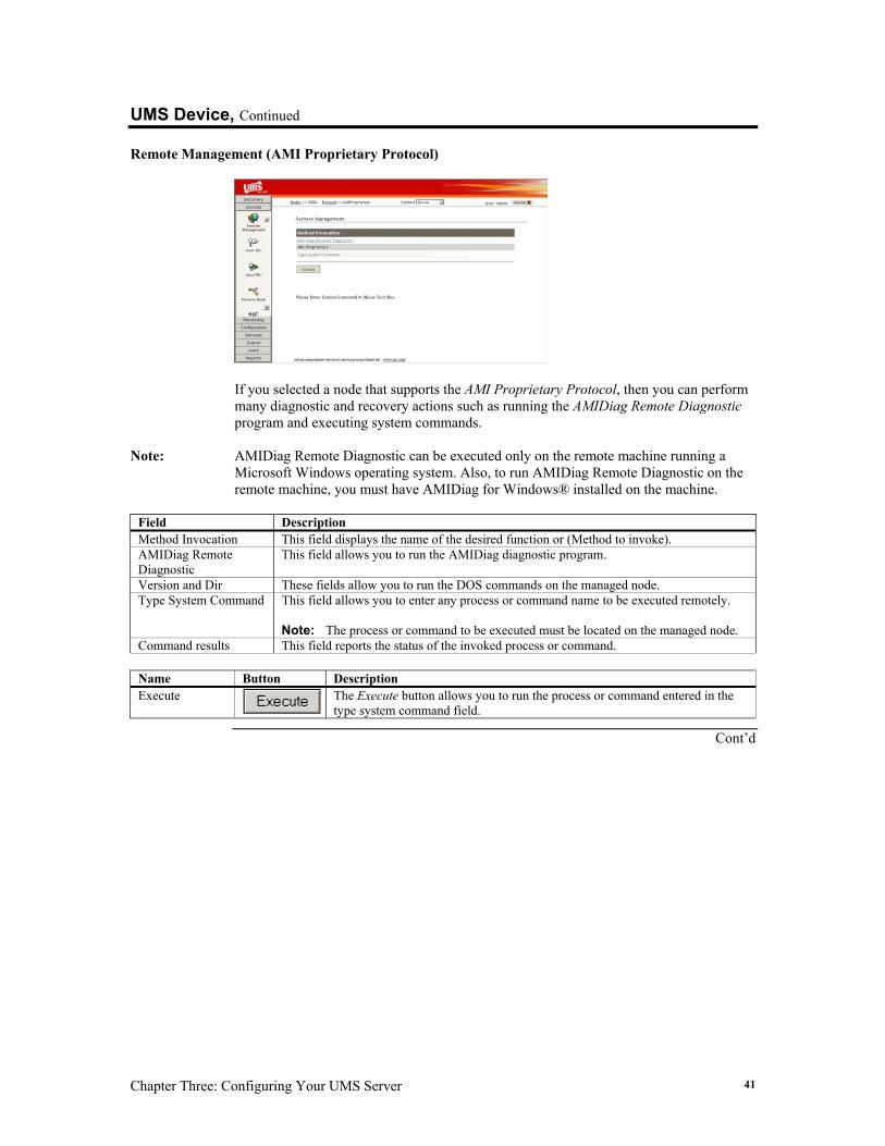
Remote Management (AMI Proprietary Protocol)
If you selected a node that supports the AMI Proprietary Protocol, then you can perform many diagnostic and recovery actions such as running the AMIDiag Remote Diagnostic program and executing system commands.
Note: AMIDiag Remote Diagnostic can be executed only on the remote machine running a
Microsoft Windows operating system. Also, to run AMIDiag Remote Diagnostic on the remote machine, you must have AMIDiag for Windows® installed on the machine.
Field Description Method Invocation This field displays the name of the desired function or (Method to invoke). AMIDiag Remote Diagnostic
This field allows you to run the AMIDiag diagnostic program.
Version and Dir These fields allow you to run the DOS commands on the managed node. Type System Command This field allows you to enter any process or command name to be executed remotely.
Note: The process or command to be executed must be located on the managed node.
Command results This field reports the status of the invoked process or command.
Name Button Description Execute
The Execute button allows you to run the process or command entered in the type system command field.
Cont’d
UMS (Version 2.0) User’s Guide 42
UMS Device, Continued
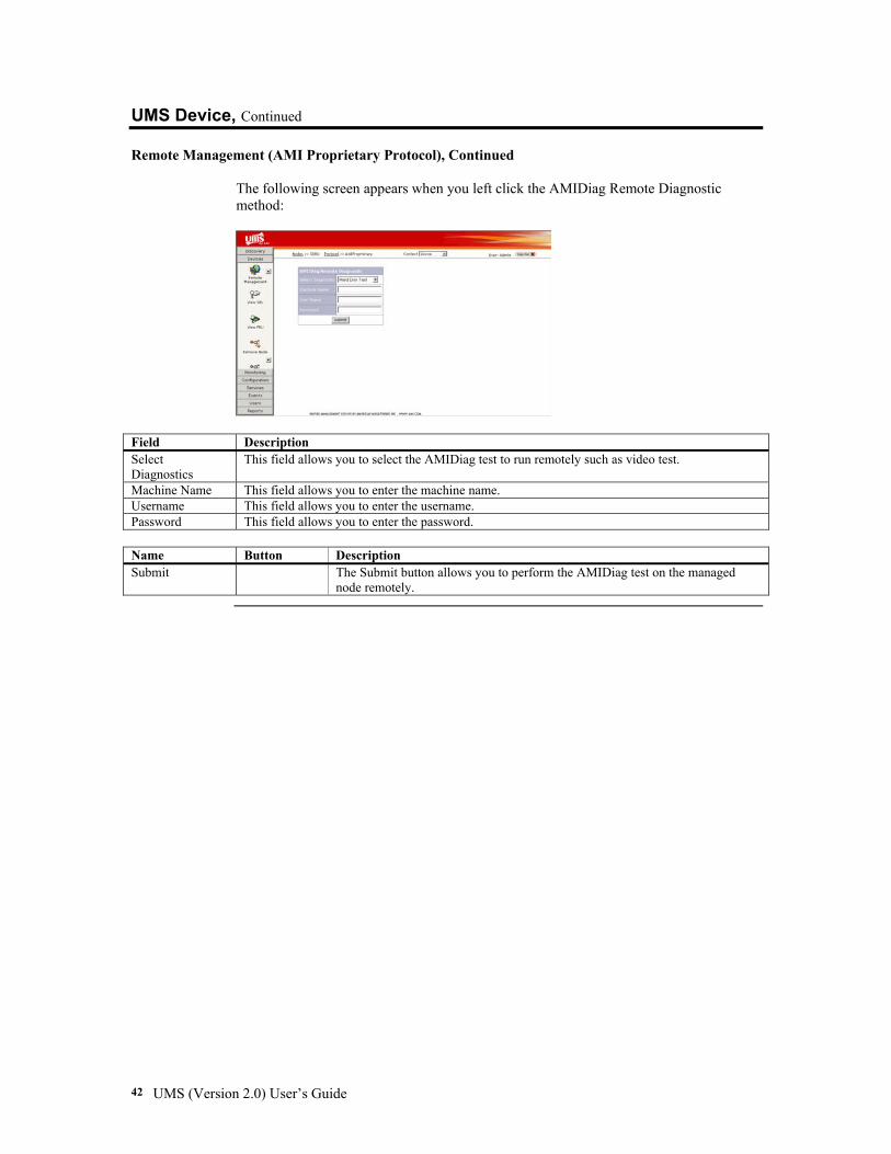
Remote Management (AMI Proprietary Protocol), Continued The following screen appears when you left click the AMIDiag Remote Diagnostic method:
Field Description Select Diagnostics
This field allows you to select the AMIDiag test to run remotely such as video test.
Machine Name This field allows you to enter the machine name. Username This field allows you to enter the username. Password This field allows you to enter the password.
Name Button Description Submit The Submit button allows you to perform the AMIDiag test on the managed
node remotely.
Chapter Three: Configuring Your UMS Server 43
UMS Device, Continued
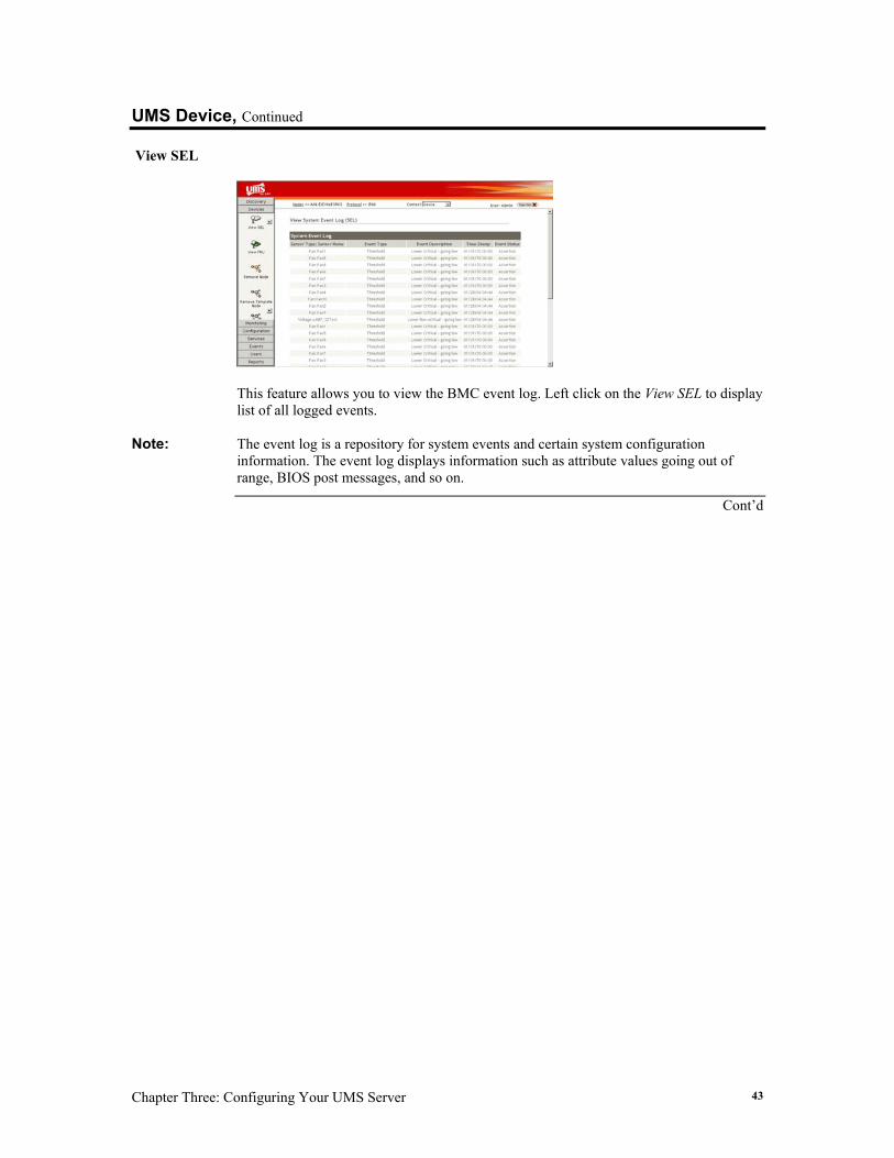
View SEL
This feature allows you to view the BMC event log. Left click on the View SEL to display list of all logged events.
Note: The event log is a repository for system events and certain system configuration
information. The event log displays information such as attribute values going out of range, BIOS post messages, and so on.
Cont’d
UMS (Version 2.0) User’s Guide 44
UMS Device, Continued
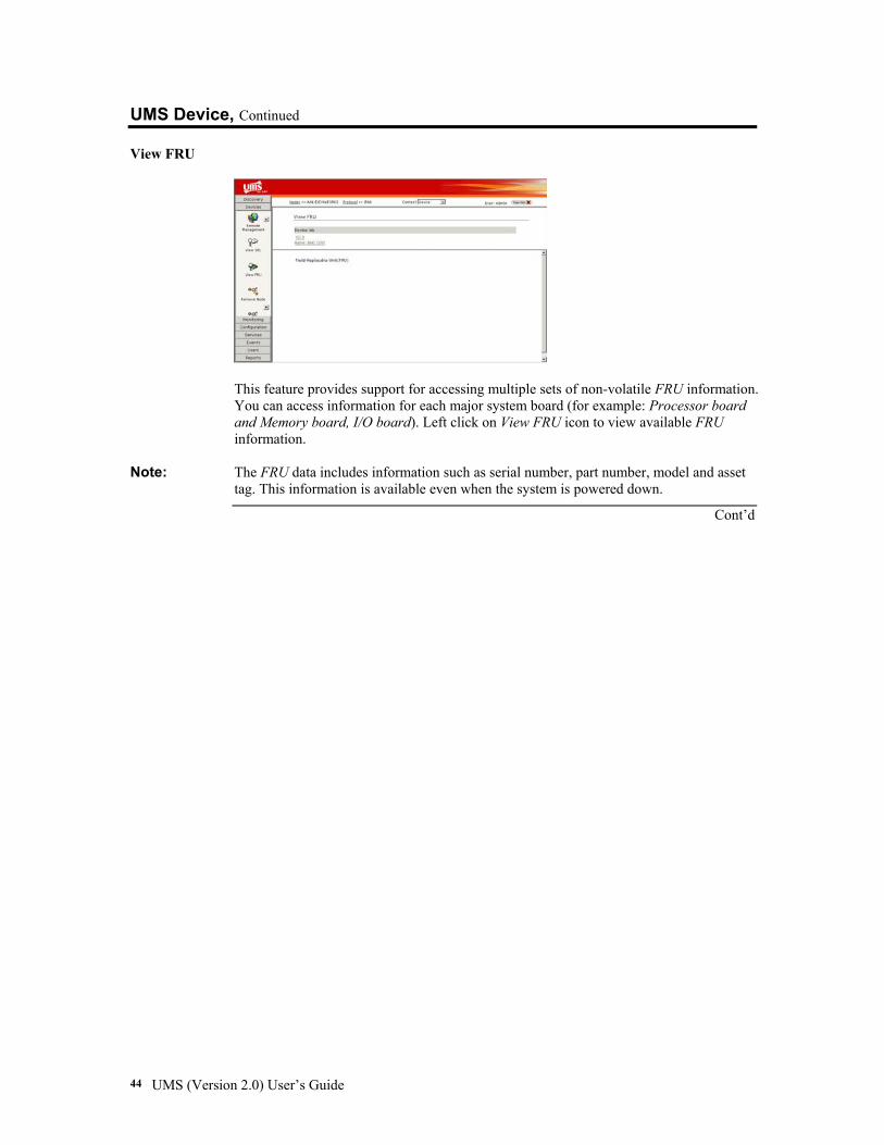
View FRU
This feature provides support for accessing multiple sets of non-volatile FRU information. You can access information for each major system board (for example: Processor board and Memory board, I/O board). Left click on View FRU icon to view available FRU information.
Note: The FRU data includes information such as serial number, part number, model and asset tag. This information is available even when the system is powered down.
Cont’d
Chapter Three: Configuring Your UMS Server 45
UMS Device, Continued
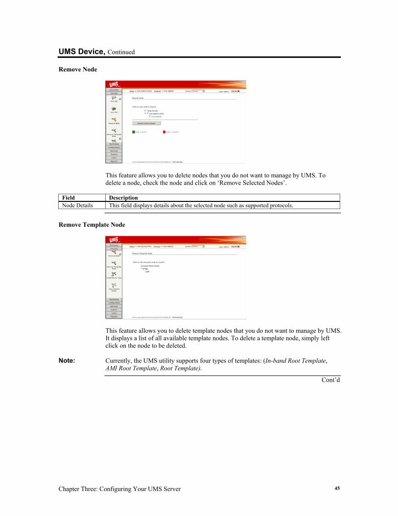
Remove Node
This feature allows you to delete nodes that you do not want to manage by UMS. To delete a node, check the node and click on ‘Remove Selected Nodes’.
Field Description Node Details This field displays details about the selected node such as supported protocols.
Remove Template Node
This feature allows you to delete template nodes that you do not want to manage by UMS. It displays a list of all available template nodes. To delete a template node, simply left click on the node to be deleted.
Note: Currently, the UMS utility supports four types of templates: (In-band Root Template, AMI Root Template, Root Template).
Cont’d
UMS (Version 2.0) User’s Guide 46
UMS Device, Continued
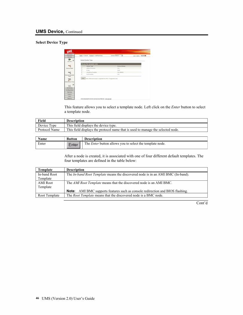
Select Device Type
This feature allows you to select a template node. Left click on the Enter button to select a template node.
Field Description Device Type This field displays the device type. Protocol Name This field displays the protocol name that is used to manage the selected node.
Name Button Description Enter
The Enter button allows you to select the template node.
After a node is created, it is associated with one of four different default templates. The four templates are defined in the table below:
Template Description In-band Root Template
The In-band Root Template means the discovered node is in an AMI BMC (In-band).
AMI Root Template
The AMI Root Template means that the discovered node is an AMI BMC. Note: AMI BMC supports features such as console redirection and BIOS flashing.
Root Template The Root Template means that the discovered node is a BMC node.
Cont’d
Chapter Three: Configuring Your UMS Server 47
UMS Device, Continued
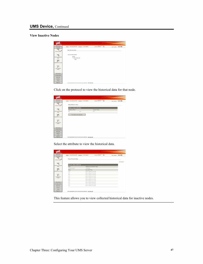
View Inactive Nodes
Click on the protocol to view the historical data for that node.
Select the attribute to view the historical data.
This feature allows you to view collected historical data for inactive nodes.
UMS (Version 2.0) User’s Guide 48
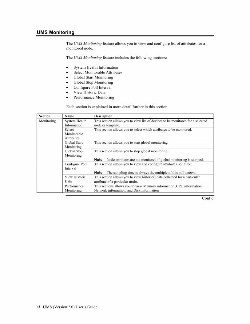
UMS Monitoring The UMS Monitoring feature allows you to view and configure list of attributes for a monitored node. The UMS Monitoring feature includes the following sections: • System Health Information • Select Monitorable Attributes • Global Start Monitoring • Global Stop Monitoring • Configure Poll Interval • View Historic Data • Performance Monitoring Each section is explained in more detail further in this section.
Section Name Description System Health Information
This section allows you to view list of devices to be monitored for a selected node or template.
Select Monitorable Attributes
This section allows you to select which attributes to be monitored.
Global Start Monitoring
This section allows you to start global monitoring.
Global Stop Monitoring
This section allows you to stop global monitoring. Note: Node attributes are not monitored if global monitoring is stopped.
Configure Poll Interval
This section allows you to view and configure attributes poll time. Note: The sampling time is always the multiple of this poll interval.
View Historic Data
This section allows you to view historical data collected for a particular attribute of a particular node.
Monitoring
Performance Monitoring
This sections allows you to view Memory information ,CPU information, Network information, and Disk information
Cont’d
Chapter Three: Configuring Your UMS Server 49
UMS Monitoring, Continued
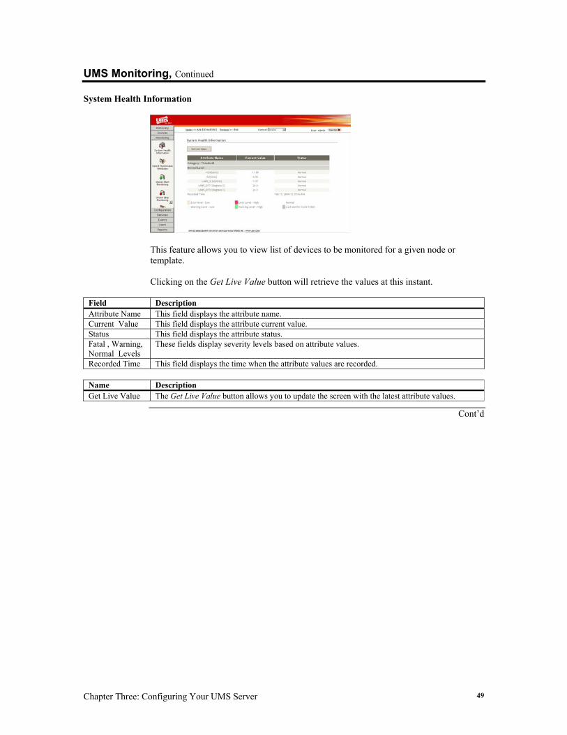
System Health Information
This feature allows you to view list of devices to be monitored for a given node or template. Clicking on the Get Live Value button will retrieve the values at this instant.
Field Description Attribute Name This field displays the attribute name. Current Value This field displays the attribute current value. Status This field displays the attribute status. Fatal , Warning, Normal Levels
These fields display severity levels based on attribute values.
Recorded Time This field displays the time when the attribute values are recorded.
Name Description Get Live Value The Get Live Value button allows you to update the screen with the latest attribute values.
Cont’d
UMS (Version 2.0) User’s Guide 50
UMS Monitoring, Continued
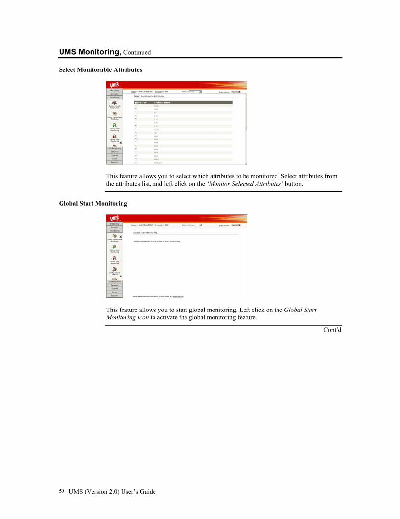
Select Monitorable Attributes
This feature allows you to select which attributes to be monitored. Select attributes from the attributes list, and left click on the ‘Monitor Selected Attributes’ button.
Global Start Monitoring
This feature allows you to start global monitoring. Left click on the Global Start Monitoring icon to activate the global monitoring feature.
Cont’d
Chapter Three: Configuring Your UMS Server 51
UMS Monitoring, Continued
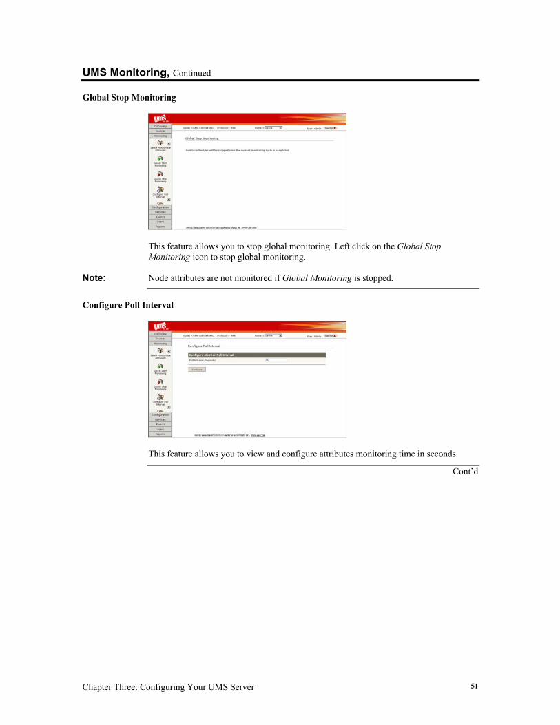
Global Stop Monitoring
This feature allows you to stop global monitoring. Left click on the Global Stop Monitoring icon to stop global monitoring.
Note: Node attributes are not monitored if Global Monitoring is stopped.
Configure Poll Interval
This feature allows you to view and configure attributes monitoring time in seconds.
Cont’d
UMS (Version 2.0) User’s Guide 52
UMS Monitoring, Continued Configure Poll Interval, Continued
Field Description Poll Interval (Seconds)
This field allows you to specify time interval used for attributes monitoring.
Name Button Description Configure
The Configure button allows you to set polling time. Note: Poll interval time is used by UMS to determine how frequently
nodes must be monitored.
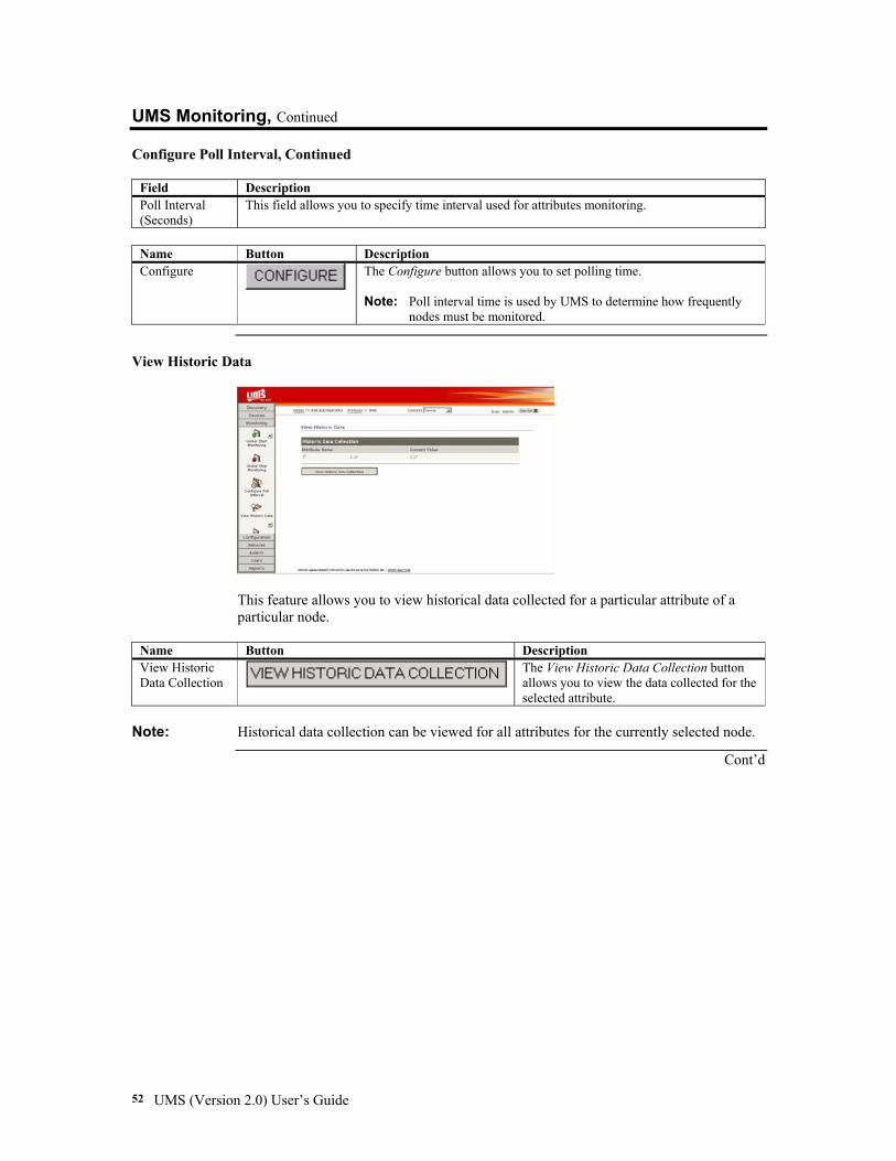
View Historic Data
This feature allows you to view historical data collected for a particular attribute of a particular node.
Name Button Description View Historic Data Collection
The View Historic Data Collection button allows you to view the data collected for the selected attribute.
Note: Historical data collection can be viewed for all attributes for the currently selected node.
Cont’d
Chapter Three: Configuring Your UMS Server 53
UMS Monitoring, Continued
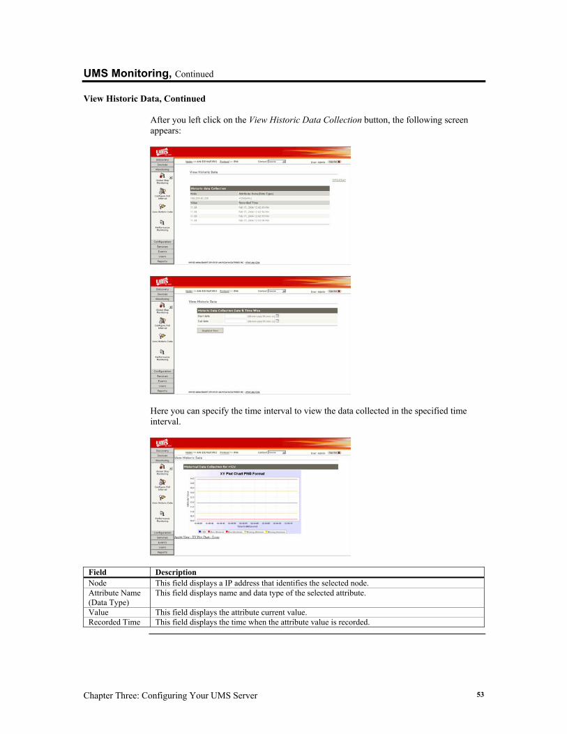
View Historic Data, Continued After you left click on the View Historic Data Collection button, the following screen appears:
Here you can specify the time interval to view the data collected in the specified time interval.
Field Description Node This field displays a IP address that identifies the selected node. Attribute Name (Data Type)
This field displays name and data type of the selected attribute.
Value This field displays the attribute current value. Recorded Time This field displays the time when the attribute value is recorded.
UMS (Version 2.0) User’s Guide 54
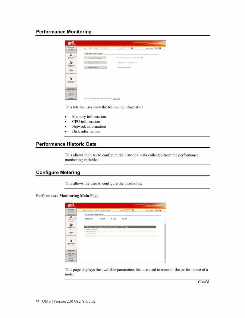
Performance Monitoring
This lets the user view the following information:
• Memory information • CPU information • Network information • Disk information
Performance Historic Data
This allows the user to configure the historical data collected from the performance monitoring variables.
Configure Metering
This allows the user to configure the thresholds.
Performance Monitoring Main Page
This page displays the available parameters that are used to monitor the performance of a node.
Cont’d
Chapter Three: Configuring Your UMS Server 55
Configure Metering, Continued
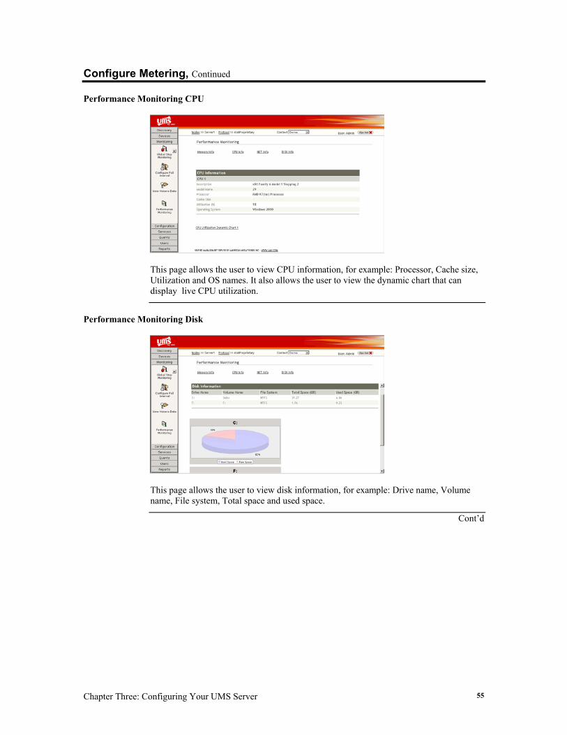
Performance Monitoring CPU
This page allows the user to view CPU information, for example: Processor, Cache size, Utilization and OS names. It also allows the user to view the dynamic chart that can display live CPU utilization.
Performance Monitoring Disk
This page allows the user to view disk information, for example: Drive name, Volume name, File system, Total space and used space.
Cont’d
UMS (Version 2.0) User’s Guide 56
Configure Metering, Continued
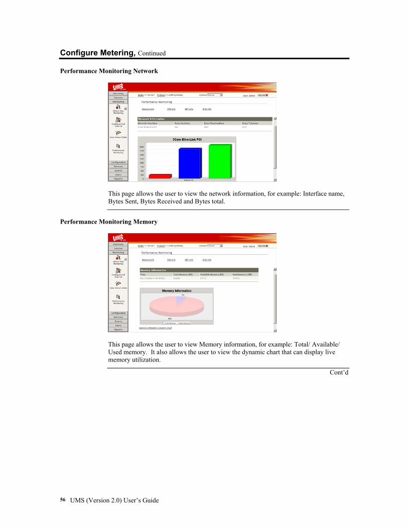
Performance Monitoring Network
This page allows the user to view the network information, for example: Interface name, Bytes Sent, Bytes Received and Bytes total.
Performance Monitoring Memory
This page allows the user to view Memory information, for example: Total/ Available/ Used memory. It also allows the user to view the dynamic chart that can display live memory utilization.
Cont’d
Chapter Three: Configuring Your UMS Server 57
Configure Metering, Continued
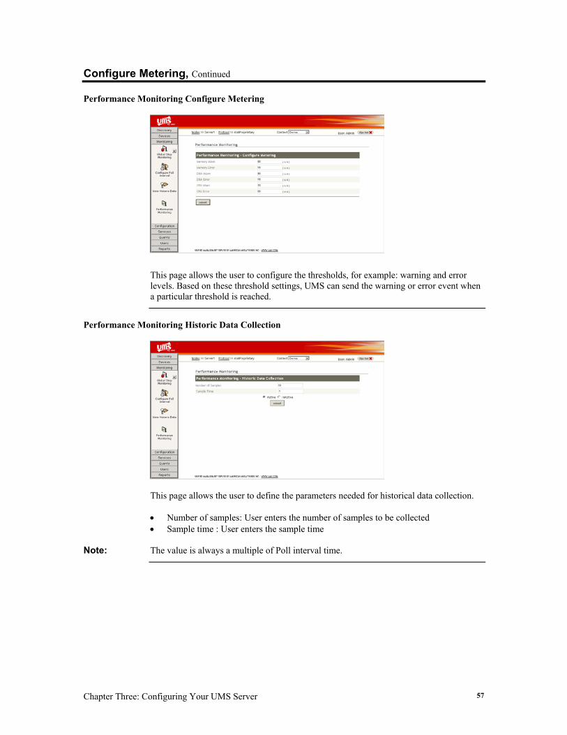
Performance Monitoring Configure Metering
This page allows the user to configure the thresholds, for example: warning and error levels. Based on these threshold settings, UMS can send the warning or error event when a particular threshold is reached.
Performance Monitoring Historic Data Collection
This page allows the user to define the parameters needed for historical data collection.
• Number of samples: User enters the number of samples to be collected • Sample time : User enters the sample time
Note: The value is always a multiple of Poll interval time.
UMS (Version 2.0) User’s Guide 58
UMS Configuration The UMS Configuration feature allows you to configure the monitoring definitions, IPMI commands, and mail server. The UMS Configuration feature includes the following sections: • Configure Monitoring • Configure IPMI Parameters • Configure Mail Server Each section is explained in more detail further in this section.
Section Name Description
Configure Monitoring
This section allows you to configure certain attributes definitions of the current selected device.
Configure IPMI Parameters
This section allows you to configure parameter attributes of the IPMI commands. Note: Currently, the UMS utility supports configuring LAN and PEF
parameters attributes.
Configuration
Configure Mail Server
This section allows you to configure the mail server details.
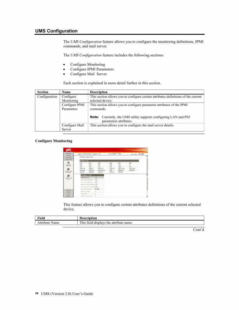
Configure Monitoring
This feature allows you to configure certain attributes definitions of the current selected device.
Field Description Attribute Name This field displays the attribute name.
Cont’d
Chapter Three: Configuring Your UMS Server 59
UMS Configuration, Continued Configure Monitoring, Continued
Field Description Upper Critical Threshold This field allows you to set the upper critical threshold value for the selected
attribute. Lower Critical Threshold This field allows you to set the lower critical threshold value for the selected
attribute. Upper non-critical Threshold This field allows you to set the upper non-critical threshold value for the selected
attribute. Lower non-critical Threshold This field allows you to set the lower non-critical threshold value for the selected
attribute. Historical Data Required This field displays whether historical data collection is required. Number of Samples This field displays the number of samples to be collected. Sample Time This field displays the time interval to collect samples for the selected attribute.
Note: The sampling time is always the multiple of the poll interval time.
Predictive Failure Count This field allows you to specify number of monitoring cycles that can be used to predict an attribute failure.
Name Button Description Submit
The Submit button allows you to update new sensor values for the selected attribute.
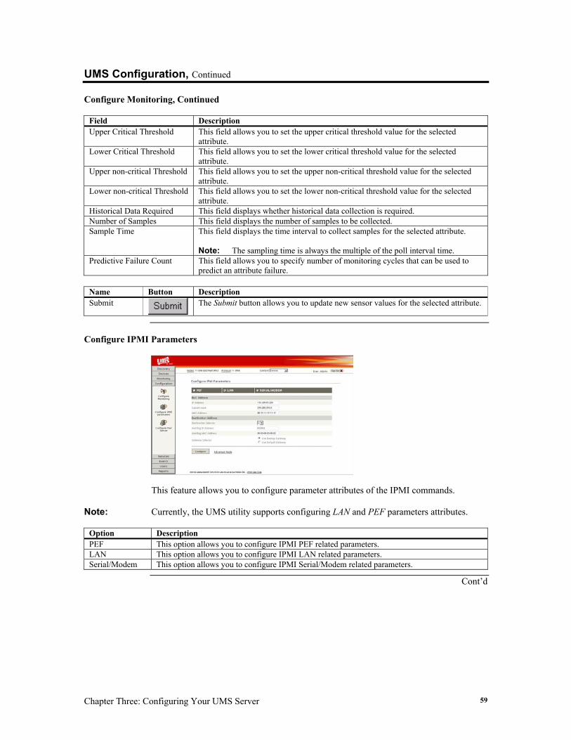
Configure IPMI Parameters
This feature allows you to configure parameter attributes of the IPMI commands.
Note: Currently, the UMS utility supports configuring LAN and PEF parameters attributes.
Option Description PEF This option allows you to configure IPMI PEF related parameters. LAN This option allows you to configure IPMI LAN related parameters. Serial/Modem This option allows you to configure IPMI Serial/Modem related parameters.
Cont’d
UMS (Version 2.0) User’s Guide 60
UMS Configuration, Continued
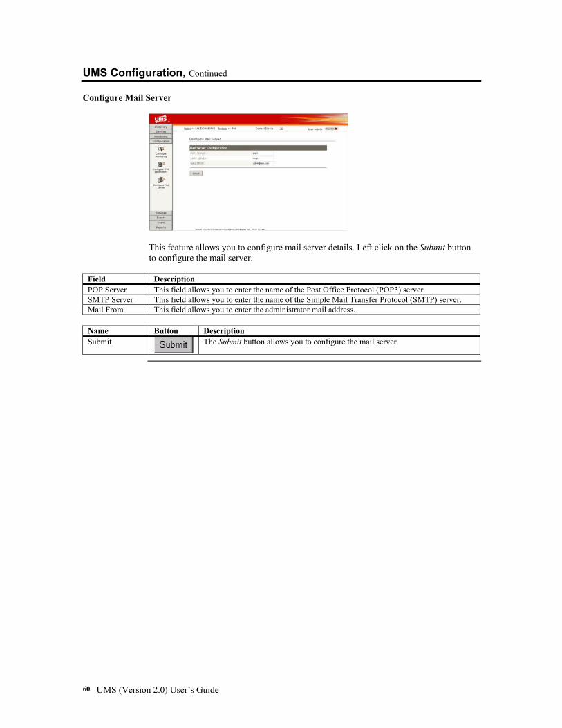
Configure Mail Server
This feature allows you to configure mail server details. Left click on the Submit button to configure the mail server.
Field Description POP Server This field allows you to enter the name of the Post Office Protocol (POP3) server. SMTP Server This field allows you to enter the name of the Simple Mail Transfer Protocol (SMTP) server. Mail From This field allows you to enter the administrator mail address.
Name Button Description Submit
The Submit button allows you to configure the mail server.
Chapter Three: Configuring Your UMS Server 61
UMS Services The UMS Services feature allows you to load services, compile loaded files and send IPMI commands. The UMS Services feature includes the following sections: • Load Services • Compile Services • IPMI Conformance Tool • CIM Browser Each section is explained in more detail further in this section.
Section Name Description Load Services This section allows you to load services and create IPMI template. Compile Files This section allows you to compile the loaded files and associate device types
with it.
Services
IPMI Conformance Tool
This section allows you to send IPMI commands to the BMC. You can send commands using an in-band or out-of-band interface. Note: The UMS utility prompts you to enter input parameters for each IPMI
command to be executed. After the input is correctly entered, then the UMS utility sends the IPMI command to the BMC of the managed node.
CIM Browser
This section allows you to view all the classes supported by that node. It lets the user view classes supported by the CIMOM repository. The CIMOM could be running in WMI or WBEM.
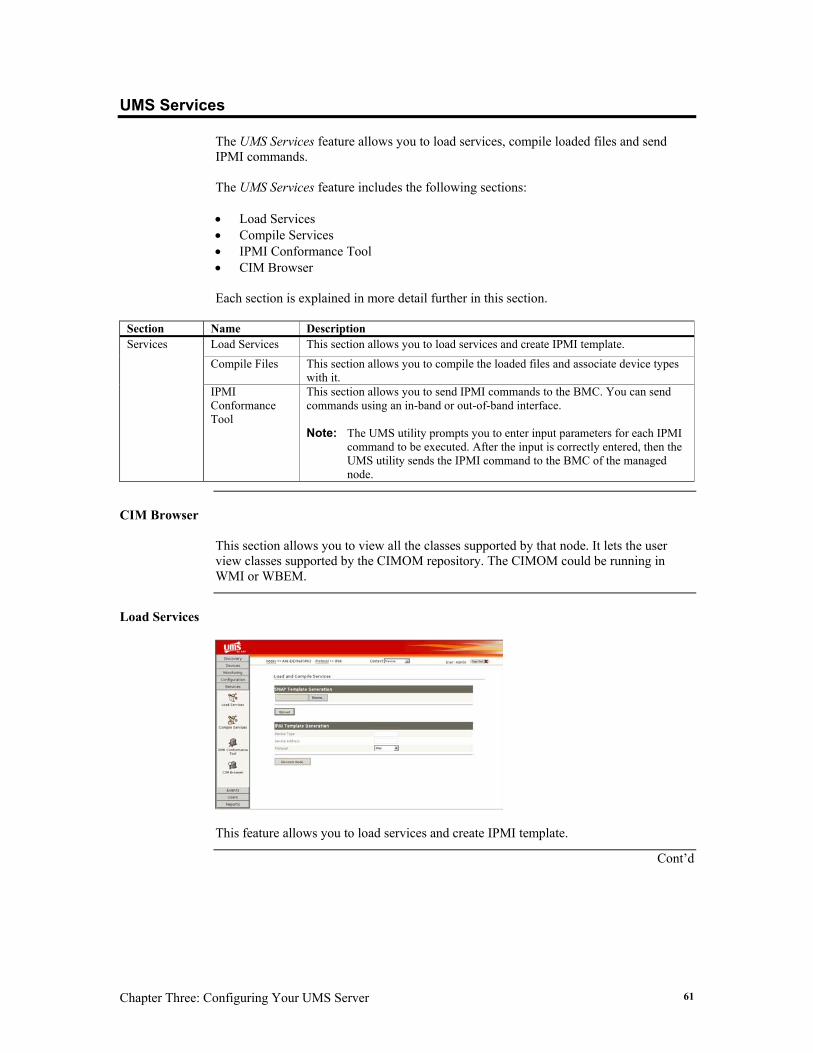
Load Services
This feature allows you to load services and create IPMI template.
Cont’d
UMS (Version 2.0) User’s Guide 62
UMS Services, Continued
Load Services, Continued
Field Description SNMP Template Generation
This field allows you to enter the file name. Note: You can also select another location by left clicking on the Browse button. Device Type This field allows you to enter the Device Type name. IPMI Discovery Device Address This field allows you to enter the Device Address ( for example IP address).
Protocol This field allows you to select the protocol name used to manage the selected node.
Name Button Description Browse
The Browse button allows you to select the file to upload.
Upload
The Upload button allows you to upload the selected file.
Discover Node The Discover Node button allows you to discover the IPMI node.
To generate an IPMI template, follow the steps outlined below:
Step Description 1 Specify the device type name, IP address and the protocol type (IPMI or In-band) to create the
template node. 2 The UMS utility discovers the node and creates the template.
Note: You can change the threshold values of the attribute by going to
Configuration/Configure Monitoring page.
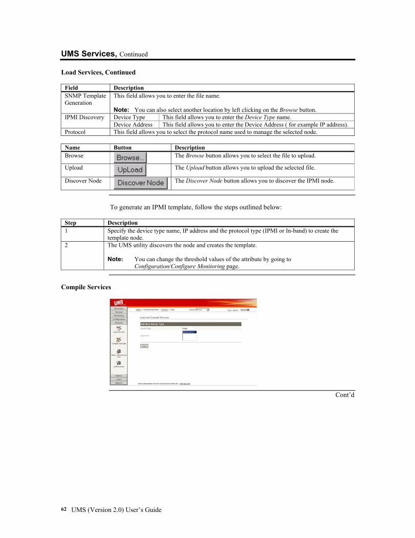
Compile Services
Cont’d

Chapter Three: Configuring Your UMS Server 63
UMS Services, Continued
Compile Services, Continued
This feature allows you to compile the loaded files and associate device type with it.
Field Description Device Type This field allows you to enter a Device Type name. Add New
Device Type Select File This field allows you to select a File to be used by this Device Type.
Name Button Description Enter
The Enter button allows you to compile files.
To edit the correct path where files are to be compiled, follow the steps outlined below:
Step Description 1 Stop the UMS server (if it is currently running). 2 Open the file named 'ums-service.xml' located under <JBOSS>/server/default/deploy 3 Edit the Directory Path
<mbeancode="com.ami.ums.mib.MibCompiler"name="ums:service=MIBCompiler"> <attribute name="DirectoryPath">[Path where the mib files are located]</attribute></mbean> For example, from windows: <mbeancode="com.ami.ums.mib.MibCompiler"name="ums:service=MIBCompiler"> <attribute name="DirectoryPath">C:/ami/ums/jboss/bin</attribute></mbean> from Linux: <mbeancode="com.ami.ums.mib.MibCompiler"name="ums:service=MIBCompiler"> <attribute name="DirectoryPath">/root/ami/ums/jboss/bin</attribute></mbean>
4 Save the new changes that you have made, and restart the UMS server.
Cont’d
UMS (Version 2.0) User’s Guide 64
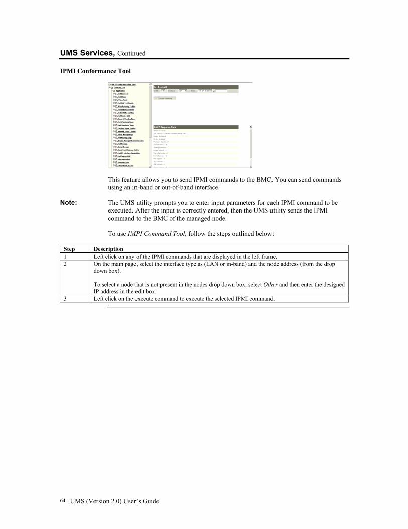
UMS Services, Continued IPMI Conformance Tool
This feature allows you to send IPMI commands to the BMC. You can send commands using an in-band or out-of-band interface.
Note: The UMS utility prompts you to enter input parameters for each IPMI command to be executed. After the input is correctly entered, then the UMS utility sends the IPMI command to the BMC of the managed node. To use IMPI Command Tool, follow the steps outlined below:
Step Description 1 Left click on any of the IPMI commands that are displayed in the left frame. 2 On the main page, select the interface type as (LAN or in-band) and the node address (from the drop
down box). To select a node that is not present in the nodes drop down box, select Other and then enter the designed IP address in the edit box.
3 Left click on the execute command to execute the selected IPMI command. .
Chapter Three: Configuring Your UMS Server 65
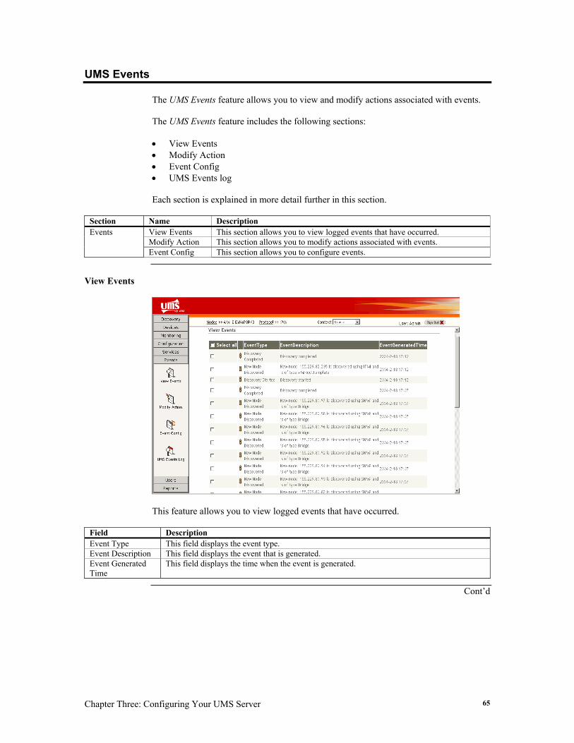
UMS Events The UMS Events feature allows you to view and modify actions associated with events. The UMS Events feature includes the following sections: • View Events • Modify Action • Event Config • UMS Events log Each section is explained in more detail further in this section.
Section Name Description View Events This section allows you to view logged events that have occurred. Modify Action This section allows you to modify actions associated with events.
Events
Event Config This section allows you to configure events.
View Events
This feature allows you to view logged events that have occurred.
Field Description Event Type This field displays the event type. Event Description This field displays the event that is generated. Event Generated Time
This field displays the time when the event is generated.
Cont’d
UMS (Version 2.0) User’s Guide 66
UMS Event, Continued
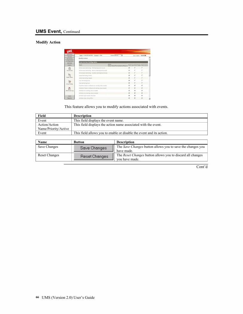
Modify Action
This feature allows you to modify actions associated with events.
Field Description Event This field displays the event name. Action/Action Name/Priority/Active
This field displays the action name associated with the event.
Event This field allows you to enable or disable the event and its action.
Name Button Description Save Changes The Save Changes button allows you to save the changes you
have made. Reset Changes The Reset Changes button allows you to discard all changes
you have made.
Cont’d
Chapter Three: Configuring Your UMS Server 67
UMS Event, Continued
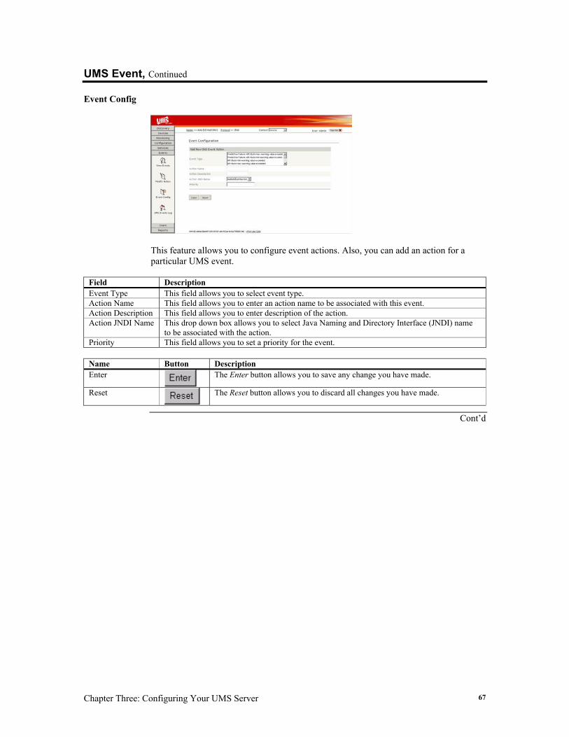
Event Config
This feature allows you to configure event actions. Also, you can add an action for a particular UMS event.
Field Description Event Type This field allows you to select event type. Action Name This field allows you to enter an action name to be associated with this event. Action Description This field allows you to enter description of the action. Action JNDI Name This drop down box allows you to select Java Naming and Directory Interface (JNDI) name
to be associated with the action. Priority This field allows you to set a priority for the event.
Name Button Description Enter
The Enter button allows you to save any change you have made.
Reset
The Reset button allows you to discard all changes you have made.
Cont’d
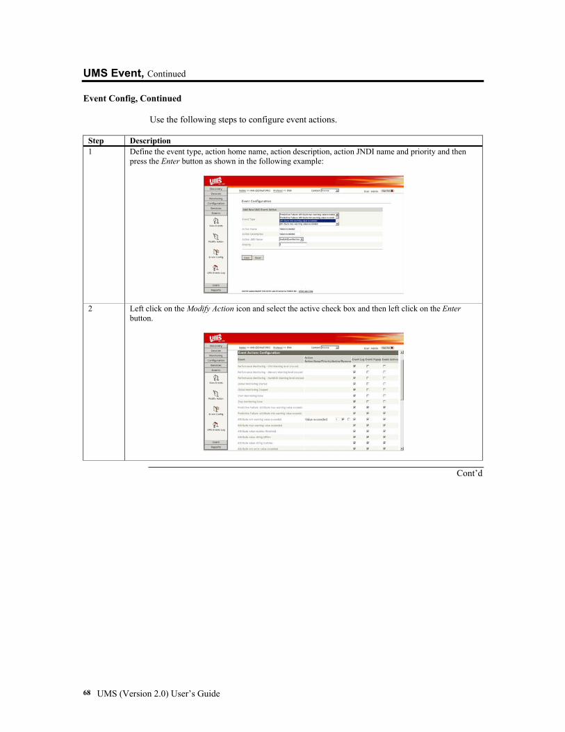
UMS (Version 2.0) User’s Guide 68
UMS Event, Continued
Event Config, Continued Use the following steps to configure event actions.
Step Description 1 Define the event type, action home name, action description, action JNDI name and priority and then
press the Enter button as shown in the following example:
2 Left click on the Modify Action icon and select the active check box and then left click on the Enter button.
Cont’d
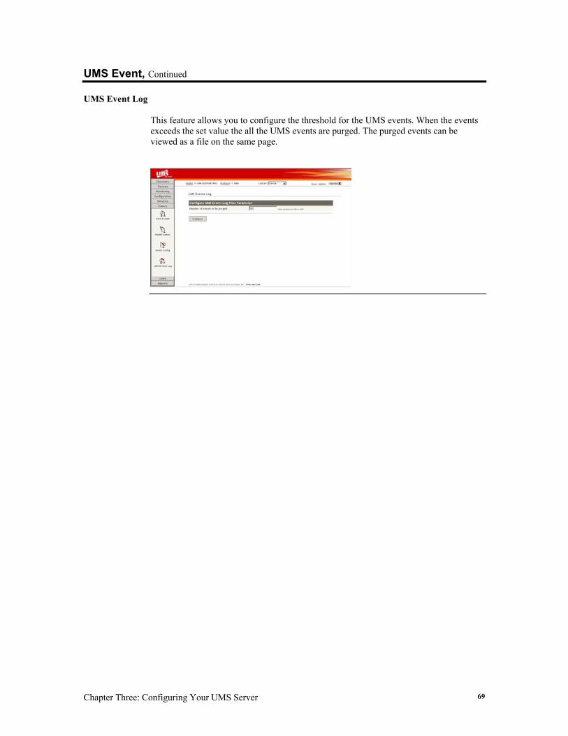
Chapter Three: Configuring Your UMS Server 69
UMS Event, Continued
UMS Event Log This feature allows you to configure the threshold for the UMS events. When the events exceeds the set value the all the UMS events are purged. The purged events can be viewed as a file on the same page.
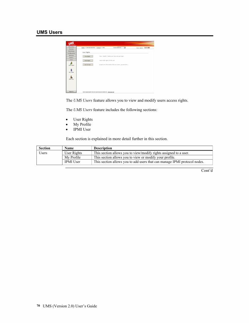
UMS (Version 2.0) User’s Guide 70
UMS Users
The UMS Users feature allows you to view and modify users access rights. The UMS Users feature includes the following sections: • User Rights • My Profile • IPMI User Each section is explained in more detail further in this section.
Section Name Description User Rights This section allows you to view/modify rights assigned to a user. My Profile This section allows you to view or modify your profile.
Users
IPMI User This section allows you to add users that can manage IPMI protocol nodes.
Cont’d
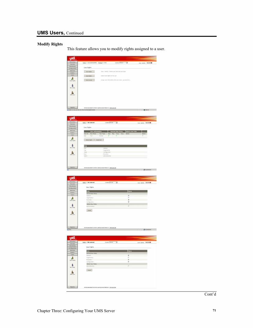
Chapter Three: Configuring Your UMS Server 71
UMS Users, Continued
Modify Rights This feature allows you to modify rights assigned to a user.
Cont’d

UMS (Version 2.0) User’s Guide 72
UMS Users, Continued
Modify Rights, Continued
Field/Option Description User Id This field displays the user identification. Username This field displays the username. User Type This field reports the user type (Normal /Admin). Select This option allows you to select the user.
Note: Only one user can be selected when you use the Modify Rights feature.
Name Button Description Submit
The Submit button allows you to select the user.
The following screen appears when you left click on the Submit button.
The system administrator assigns roles to the UMS users. The UMS utility supports five roles. To select a role, left click on any of the check boxes. The access permissions for each role are defined in the following table.
Role Description
The General role allows you to access UMS general features such as viewing data. The following shows UMS features that are available by assigning the general role to a user. UMS Feature Module Discover Nodes Discovery Module Select Device Devices Module System Health Information Monitoring Module Configure Monitoring Configuration Module Load Services Services Module Historic Data Files Reports Module View Events Events Module
General
User Rights Users Module
Cont’d
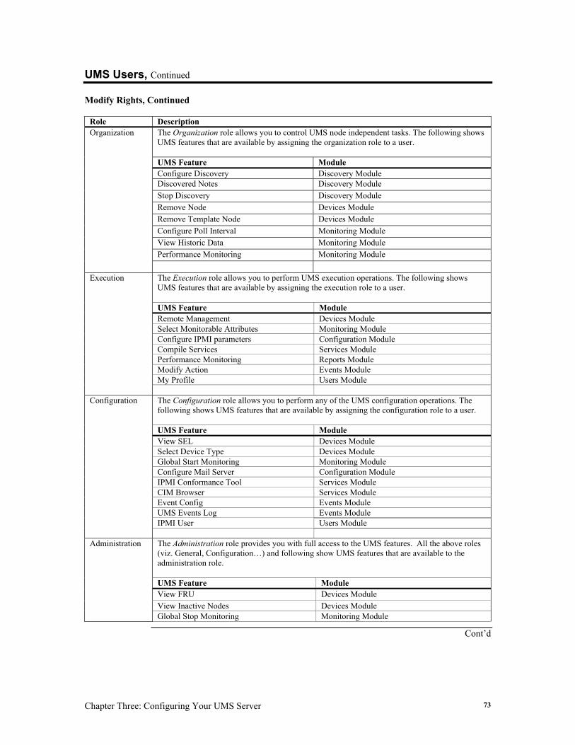
Chapter Three: Configuring Your UMS Server 73
UMS Users, Continued
Modify Rights, Continued
Role Description The Organization role allows you to control UMS node independent tasks. The following shows UMS features that are available by assigning the organization role to a user. UMS Feature Module Configure Discovery Discovery Module Discovered Notes Discovery Module Stop Discovery Discovery Module Remove Node Devices Module Remove Template Node Devices Module Configure Poll Interval Monitoring Module View Historic Data Monitoring Module Performance Monitoring Monitoring Module
Organization
The Execution role allows you to perform UMS execution operations. The following shows UMS features that are available by assigning the execution role to a user. UMS Feature Module Remote Management Devices Module Select Monitorable Attributes Monitoring Module Configure IPMI parameters Configuration Module Compile Services Services Module Performance Monitoring Reports Module Modify Action Events Module My Profile Users Module
Execution
The Configuration role allows you to perform any of the UMS configuration operations. The following shows UMS features that are available by assigning the configuration role to a user. UMS Feature Module View SEL Devices Module Select Device Type Devices Module Global Start Monitoring Monitoring Module Configure Mail Server Configuration Module IPMI Conformance Tool Services Module CIM Browser Services Module Event Config Events Module UMS Events Log Events Module IPMI User Users Module
Configuration
The Administration role provides you with full access to the UMS features. All the above roles (viz. General, Configuration…) and following show UMS features that are available to the administration role. UMS Feature Module View FRU Devices Module View Inactive Nodes Devices Module
Administration
Global Stop Monitoring Monitoring Module
Cont’d

UMS (Version 2.0) User’s Guide 74
UMS Users, Continued
Modify Rights, Continued
Name Button Description Submit
The Submit button allows you to assign roles to a user.
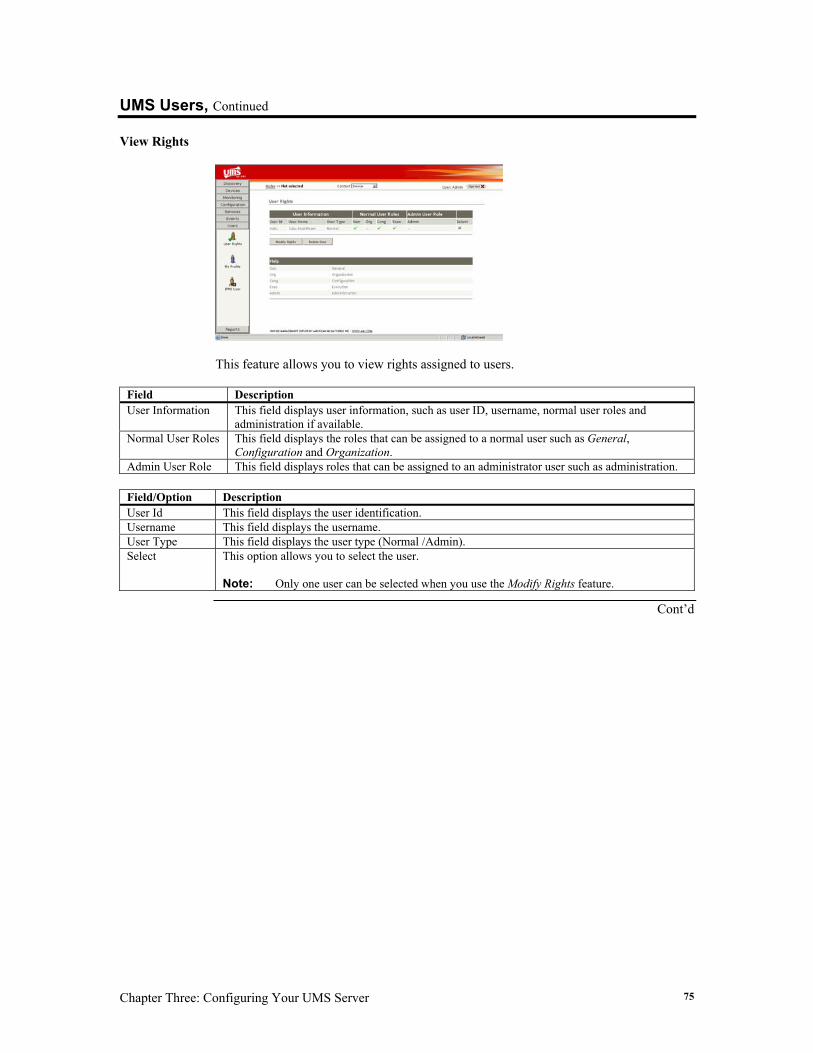
Chapter Three: Configuring Your UMS Server 75
UMS Users, Continued
View Rights
This feature allows you to view rights assigned to users.
Field Description User Information This field displays user information, such as user ID, username, normal user roles and
administration if available. Normal User Roles This field displays the roles that can be assigned to a normal user such as General,
Configuration and Organization. Admin User Role This field displays roles that can be assigned to an administrator user such as administration.
Field/Option Description User Id This field displays the user identification. Username This field displays the username. User Type This field displays the user type (Normal /Admin). Select This option allows you to select the user.
Note: Only one user can be selected when you use the Modify Rights feature.
Cont’d
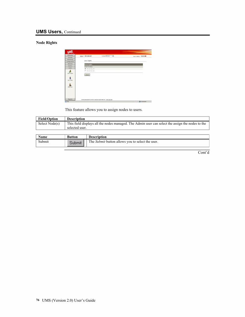
UMS (Version 2.0) User’s Guide 76
UMS Users, Continued
Node Rights
This feature allows you to assign nodes to users.
Field/Option Description Select Node(s) This field displays all the nodes managed. The Admin user can select the assign the nodes to the
selected user.
Name Button Description Submit
The Submit button allows you to select the user.
Cont’d
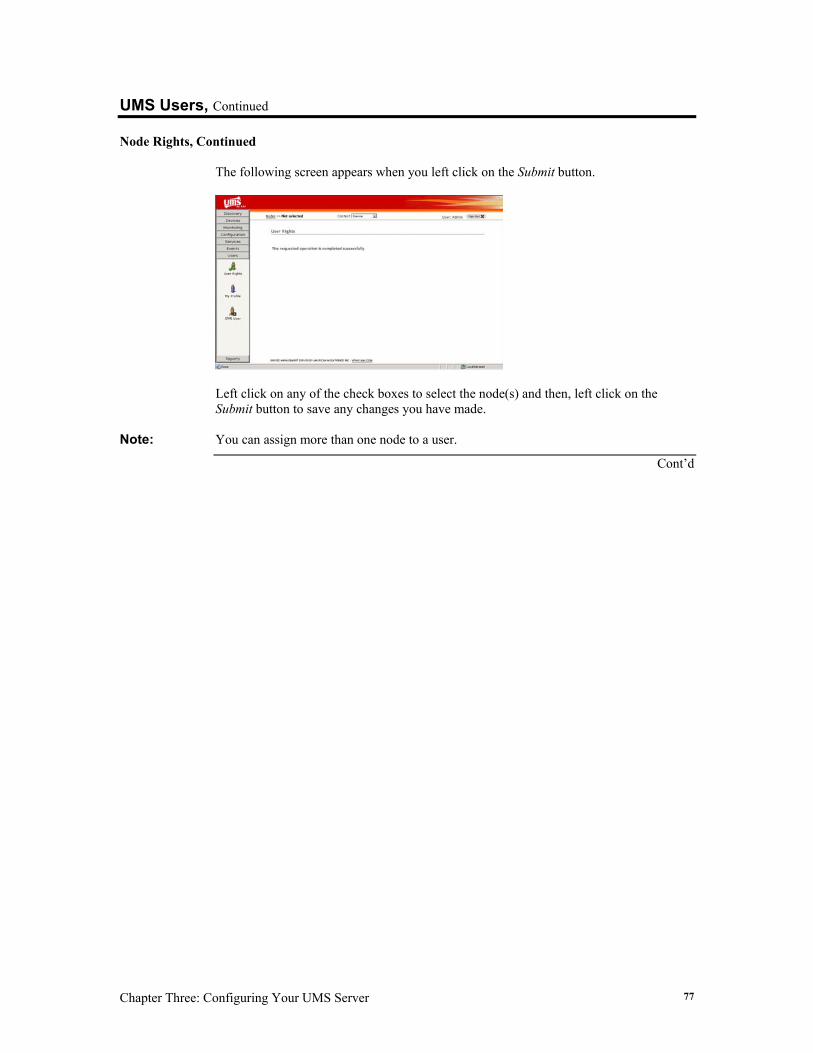
Chapter Three: Configuring Your UMS Server 77
UMS Users, Continued
Node Rights, Continued The following screen appears when you left click on the Submit button.
Left click on any of the check boxes to select the node(s) and then, left click on the Submit button to save any changes you have made.
Note: You can assign more than one node to a user.
Cont’d
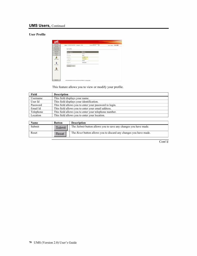
UMS (Version 2.0) User’s Guide 78
UMS Users, Continued
User Profile
This feature allows you to view or modify your profile.
Field Description Username This field displays your name. User Id This field displays your identification. Password This field allows you to enter your password to login. Email Id This field allows you to enter your email address. Telephone This field allows you to enter your telephone number. Location This field allows you to enter your location.
Name Button Description Submit
The Submit button allows you to save any changes you have made.
Reset
The Reset button allows you to discard any changes you have made.
Cont’d
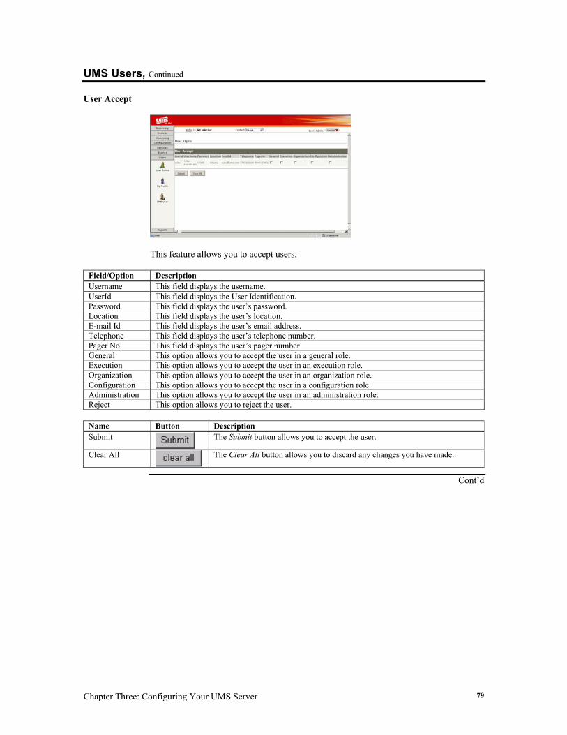
Chapter Three: Configuring Your UMS Server 79
UMS Users, Continued
User Accept
This feature allows you to accept users.
Field/Option Description Username This field displays the username. UserId This field displays the User Identification. Password This field displays the user’s password. Location This field displays the user’s location. E-mail Id This field displays the user’s email address. Telephone This field displays the user’s telephone number. Pager No This field displays the user’s pager number. General This option allows you to accept the user in a general role. Execution This option allows you to accept the user in an execution role. Organization This option allows you to accept the user in an organization role. Configuration This option allows you to accept the user in a configuration role. Administration This option allows you to accept the user in an administration role. Reject This option allows you to reject the user.
Name Button Description Submit
The Submit button allows you to accept the user.
Clear All
The Clear All button allows you to discard any changes you have made.
Cont’d
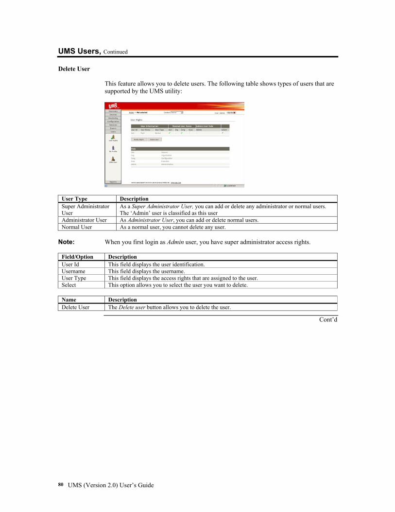
UMS (Version 2.0) User’s Guide 80
UMS Users, Continued
Delete User
This feature allows you to delete users. The following table shows types of users that are supported by the UMS utility:
User Type Description Super Administrator User
As a Super Administrator User, you can add or delete any administrator or normal users. The ‘Admin’ user is classified as this user
Administrator User As Administrator User, you can add or delete normal users. Normal User As a normal user, you cannot delete any user.
Note: When you first login as Admin user, you have super administrator access rights.
Field/Option Description User Id This field displays the user identification. Username This field displays the username. User Type This field displays the access rights that are assigned to the user. Select This option allows you to select the user you want to delete.
Name Description Delete User The Delete user button allows you to delete the user.
Cont’d
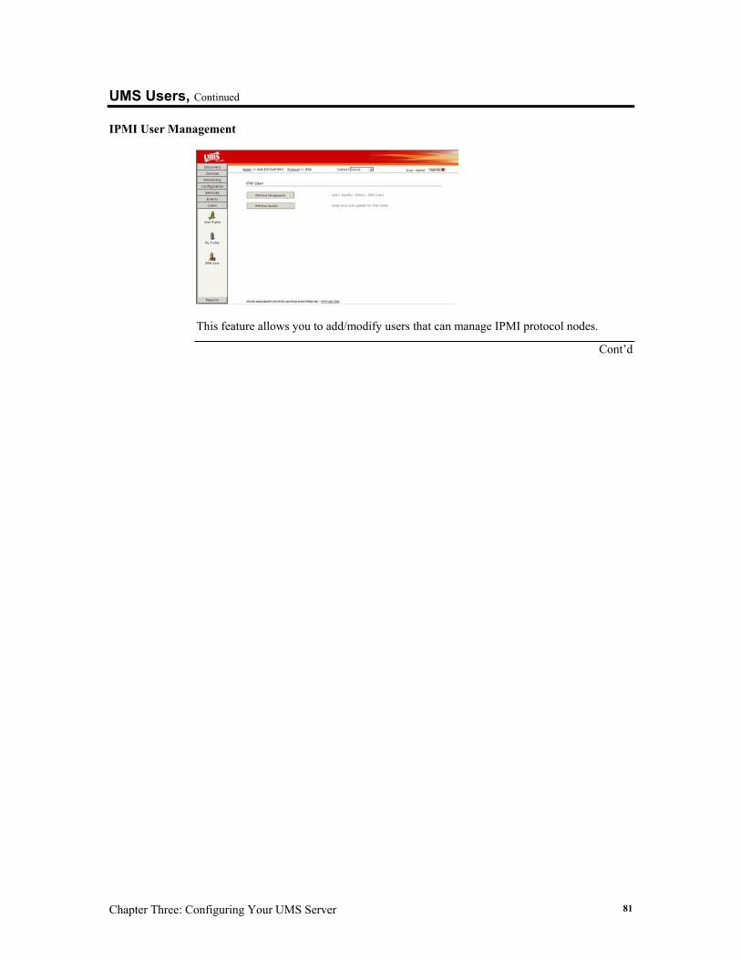
Chapter Three: Configuring Your UMS Server 81
UMS Users, Continued
IPMI User Management
This feature allows you to add/modify users that can manage IPMI protocol nodes.
Cont’d
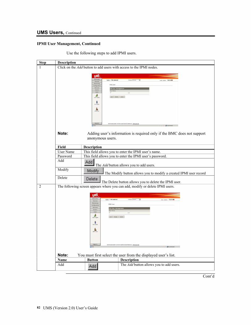
UMS (Version 2.0) User’s Guide 82
UMS Users, Continued
IPMI User Management, Continued
Use the following steps to add IPMI users.
Step Description Click on the Add button to add users with access to the IPMI nodes.
Note: Adding user’s information is required only if the BMC does not support
anonymous users. Field Description User Name This field allows you to enter the IPMI user’s name. Password This field allows you to enter the IPMI user’s password. Add
The Add button allows you to add users. Modify
The Modify button allows you to modify a created IPMI user record
1
Delete The Delete button allows you to delete the IPMI user.
The following screen appears where you can add, modify or delete IPMI users.
Note: You must first select the user from the displayed user’s list. Name Button Description
2
Add
The Add button allows you to add users.
Cont’d
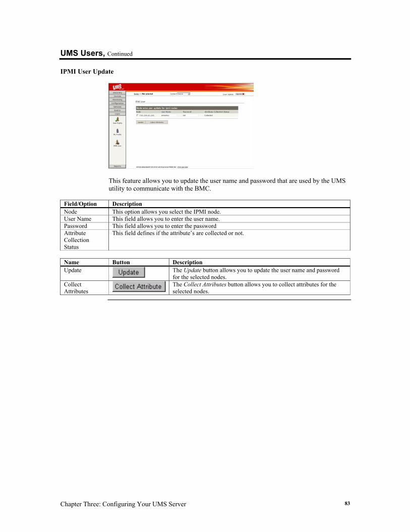
Chapter Three: Configuring Your UMS Server 83
UMS Users, Continued
IPMI User Update
This feature allows you to update the user name and password that are used by the UMS utility to communicate with the BMC.
Field/Option Description Node This option allows you select the IPMI node. User Name This field allows you to enter the user name. Password This field allows you to enter the password Attribute Collection Status
This field defines if the attribute’s are collected or not.
Name Button Description Update
The Update button allows you to update the user name and password for the selected nodes.
Collect Attributes
The Collect Attributes button allows you to collect attributes for the selected nodes.
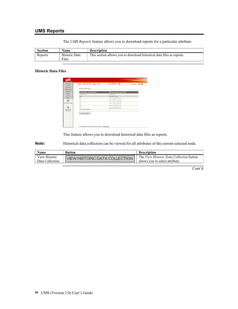
UMS (Version 2.0) User’s Guide 84
UMS Reports The UMS Reports feature allows you to download reports for a particular attribute.
Section Name Description Reports Historic Data
Files This section allows you to download historical data files as reports.
Historic Data Files
This feature allows you to download historical data files as reports.
Note: Historical data collection can be viewed for all attributes of the current selected node.
Name Button Description View Historic Data Collection
The View Historic Data Collection button allows you to select attribute.
Cont’d
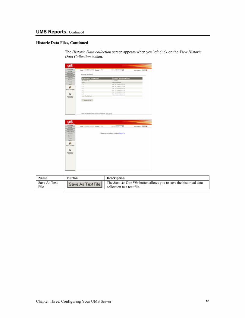
Chapter Three: Configuring Your UMS Server 85
UMS Reports, Continued
Historic Data Files, Continued The Historic Data collection screen appears when you left click on the View Historic Data Collection button.
Name Button Description Save As Text File
The Save As Text File button allows you to save the historical data collection to a text file.
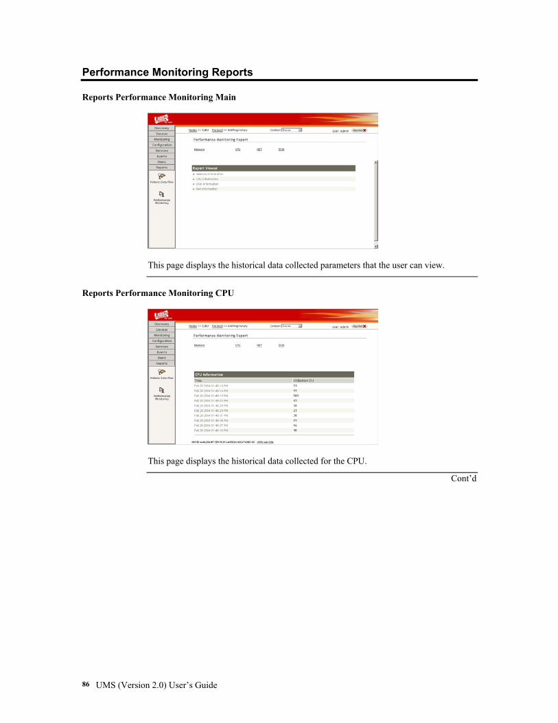
UMS (Version 2.0) User’s Guide 86
Performance Monitoring Reports Reports Performance Monitoring Main
This page displays the historical data collected parameters that the user can view.
Reports Performance Monitoring CPU
This page displays the historical data collected for the CPU.
Cont’d
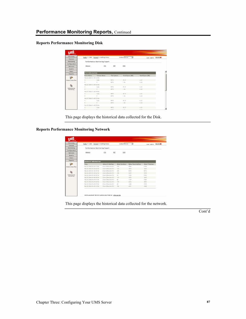
Chapter Three: Configuring Your UMS Server 87
Performance Monitoring Reports, Continued Reports Performance Monitoring Disk
This page displays the historical data collected for the Disk.
Reports Performance Monitoring Network
This page displays the historical data collected for the network.
Cont’d
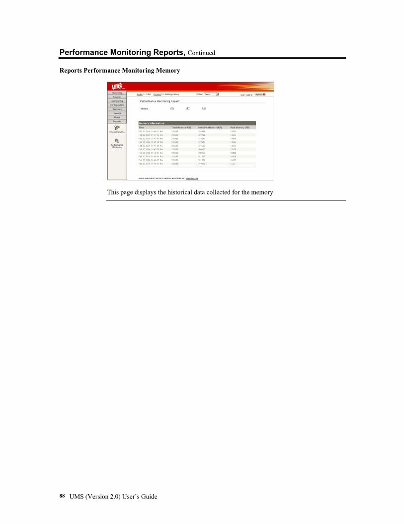
UMS (Version 2.0) User’s Guide 88
Performance Monitoring Reports, Continued Reports Performance Monitoring Memory
This page displays the historical data collected for the memory.

Appendix A: References 89
Appendix A References
References
Word Description AMI American Megatrends, Inc UMS Unified Management Server SEL System Event Log FRU Field Replaceable Unit IPMI Intelligent Platform Management Interface SNMP Simple Network Management Protocol RMCP Remote Management Control Protocol UDP User Datagram Protocol BMC Base Management Controller JMX Java Management Extensions KCS Keyboard Controller Style SMIC Server Management Interface Chip SDK Software Development Kit LAN Local Area Network PEF Platform Event Filtering SMTP Simple Mail Transfer Protocol POP Post Office Protocol JNDI Java Naming and Directory Interface

UMS (Version 2.0) User’s Guide 90
Index 91
Index
B Before You Start, 5 Best Practice, 3
C CIM Browser, 28, 61, 73 Compile Services, 61, 62, 63, 73 Configure Discovery, 27, 30, 32, 35, 36, 73 Configure Discovery Cycle, 32, 35, 36 Configure Display Name, 32, 36 Configure IPMI Parameters, 2, 28, 58, 59 Configure Mail Server, 2, 28, 58, 60, 73 Configure Metering, 54, 55, 56, 57 Configure Monitoring, 28, 58, 59, 62, 72 Configure Network Model, 32, 33, 34 Configure Poll Interval, 2, 28, 48, 51, 52, 73 Configuring Your UMS Server, 25 Connecting, 20, 21, 22
D Default Username and Password, 26 Delete User, 80 Discover Nodes, 27, 30, 31, 72 Discovered Nodes, 2, 6, 27, 30, 37
E Event Config, 28, 65, 67, 68, 73
F Features, 2
G Global Start Monitoring, 2, 28, 48, 50, 73 Global Stop Monitoring, 2, 28, 48, 51, 73
H Historic Data Files, 29, 72, 84, 85
I Installation, 7, 8, 9, 10, 11, 12, 13, 14, 15, 16, 17,
18, 19 Installing Java Development Kit, 7, 8, 9, 10, 11,
12 Installing UMS, 13, 14, 15, 16 Intrusive and Non-Intrusive Methods, 3 IPMI Conformance Tool, 28, 61, 64, 73
IPMI User Management, 81, 82 IPMI User Update, 83
J Java Plugins, 5
L Load Services, 28, 61, 62, 72
M Macromedia Plugins, 6 Modify Action, 28, 65, 66, 68, 73 Modify Rights, 71, 72, 73, 74, 75
N Node Rights, 76, 77
O Operating System, 1, 2, 5
P Performance Historic Data, 54 Performance Monitoring, 2, 28, 29, 48, 54, 55, 56,
57, 73, 86, 87, 88 Performance Monitoring Configure Metering, 57 Performance Monitoring CPU, 55 Performance Monitoring Disk, 55 Performance Monitoring Historic Data Collection,
57 Performance Monitoring Main Page, 54 Performance Monitoring Memory, 56 Performance Monitoring Network, 56 Performance Monitoring Reports, 86, 87, 88 Prerequisites, 5
Q Quick Installation, 5
R References, 89 Remote Management, 3, 27, 38, 39, 40, 41, 42,
73, 89 Remote Management (AMI Proprietary Protocol),
41, 42 Remote Management (IPMI-Protocol), 40 Remove Node, 27, 38, 45, 73 Remove Template Node, 27, 38, 45, 73
UMS (Version 2.0) User’s Guide 92
Reports Performance Monitoring CPU, 86 Reports Performance Monitoring Disk, 87 Reports Performance Monitoring Main, 86 Reports Performance Monitoring Memory, 88 Reports Performance Monitoring Network, 87 Required Plugins, 5, 6 Running UMS Agent from Windows, 17 Running UMS from a Command Prompt, 18, 19 Running UMS Server from Windows, 17 Running UMS Server/Agent from Windows, 18
S Section Icons and Functions, 27, 28, 29 Select Device, 27, 38, 39, 46, 72, 73 Select Device Type, 27, 38, 46, 73 Select Monitorable Attributes, 28, 48, 50, 73 Stop Discovery, 2, 27, 30, 37, 73 Stopping UMS from a Command Prompt, 19 Supported Protocols, 1 System Health Information, 28, 48, 49, 72
U UMS Configuration, 58, 59, 60
UMS Device, 38, 39, 40, 41, 42, 43, 44, 45, 46, 47
UMS Discovery, 30, 31, 32, 33, 34, 35, 36, 37 UMS Event Log, 69 UMS Events, 65, 73 UMS Monitoring, 48, 49, 50, 51, 52, 53 UMS Reports, 84, 85 UMS Services, 61, 62, 63, 64 UMS Users, 70, 71, 72, 73, 74, 75, 76, 77, 78, 79,
80, 81, 82, 83 Uninstalling UMS, 23 User Accept, 79 User Profile, 2, 78
V View Events, 28, 65, 72 View FRU, 27, 38, 44, 73 View Historic Data, 28, 48, 52, 53, 73, 84, 85 View Inactive Nodes, 27, 38, 47, 73 View Rights, 75 View SEL, 27, 38, 43, 73