UMLA / UMLVA Oil Fired Warm Air Furnaces - Olsen USA |...
24
Direct Vent Supplement UMLA / UMLVA Oil Fired Warm Air Furnaces INSTALLATION, OPERATION & MAINTENANCE MANUAL P/N 240011300, Rev. D [09/30/2017] ALL INSTALLATIONS MUST MEET ALL LOCAL, PROVINCIAL/ STATE, AND FEDERAL CODES WHICH MAY DIFFER FROM THIS MANUAL WARNING Fire, explosion, asphyxiation and electrical shock hazard. Improper installation could result in death or serious injury. Read this manual and understand all requirements before beginning installation. ! NOTICE Information contained in this manual pertains to oil fired direct vent furnaces equipped with manufacturer provided and field installed blocked vent safety control system (pressure switch). Manufactured by: ECR International Inc. 2201 Dwyer Avenue, Utica, NY 13501 Tel. 800 253 7900 www.ecrinternational.com
Transcript of UMLA / UMLVA Oil Fired Warm Air Furnaces - Olsen USA |...

Direct Vent SupplementUMLA / UMLVA Oil Fired Warm Air Furnaces
INSTALLATION, OPERATION & MAINTENANCE MANUAL
P/N 240011300, Rev. D [09/30/2017]
ALL INSTALLATIONS MUST MEET ALL LOCAL, PROVINCIAL/STATE, AND FEDERAL CODES WHICH MAY DIFFER FROM THIS
MANUAL
WARNINGFire, explosion, asphyxiation and electrical shock hazard. Improper installation could result in death or serious injury. Read this manual and understand all requirements before beginning installation.
!
NOTICEInformation contained in this manual pertains to oil fired direct vent furnaces equipped with manufacturer provided and field installed blocked vent safety control system (pressure switch).
Manufactured by:ECR International Inc.
2201 Dwyer Avenue, Utica, NY 13501Tel. 800 253 7900
www.ecrinternational.com

2 P/N 240011300, Rev. D [09/30/2017]
DIRECT VENT OIL FIRED WARM AIR FURNACE
ALL INSTALLATIONS MUST MEET ALL LOCAL, PROVINCIAL/STATE, AND FEDERAL CODES WHICH MAY DIFFER FROM THIS MANUAL
Read and understand this manual before beginning installation. Instructions must be kept with furnace
for future reference.

3 P/N 240011300, Rev. D [09/30/2017]
WARNINGS AND SAFETY SYMBOLS
DIRECT VENT OIL FIRED WARM AIR FURNACE
1. DIRECT VENTING OF OLSEN OIL FIRED FURNACES ..................................................................... 4
2. VENT TERMINAL LOCATION ...................................................................................................... 5
3. VENT TERMINAL INSTALLATION ................................................................................................ 6
4. VENT TERMINAL RISER KIT ..................................................................................................... 6
5. DIRECT VENT INTAKE AIR PIPE INSTALLATION ........................................................................... 7
6. VENTING INSTALLATION - DIRECT VENT .................................................................................... 8
7. BLOCKED VENT SAFETY SWITCH PRESSURE TUBING CONNECTIONS. ............................................ 9
8. OIL BURNER SETUP ................................................................................................................10
9. FURNACE SET UP ADJUSTMENTS .............................................................................................14
10. BLOCKED VENT SAFETY SHUT OFF SYSTEM ..............................................................................14
11. SEQUENCE OF OPERATION .....................................................................................................14
12. FINAL CHECK OUT.................................................................................................................14
DIRECT VENTING WIRING DIAGRAM ............................................................................................15
DIRECT VENTING OF OLSEN OIL FIRED FURNACES - VENTING COMPONENTS .....................................16
VENTING COMPONENTS/MATCHING GUIDE ....................................................................................17
DIRECT VENT - PARTS IDENTIFICATION ........................................................................................17
BECKETT BURNER BLOCKED VENT SAFETY (BVS) OPERATION ..........................................................18
BECKETT BURNER TROUBLESHOOTING .........................................................................................19
RIELLO 40BF BLOCKED VENT SAFETY (BVS) OPERATION .................................................................21
RIELLO 40BF BURNER TROUBLESHOOTING ....................................................................................22
HOMEOWNER’S REFERENCE TABLE ...............................................................................................23
DANGERIndicates a hazardous situation which, if not avoided, WILL result in death or serious injury
!
WARNINGIndicates a hazardous situation which, if not avoided, could result in death or serious injury.
!
CAUTIONIndicates a hazardous situation which, if not avoided, could result in minor or moderate injury.
NOTICEUsed to address practices not related to personal injury.

4 P/N 240011300, Rev. D [09/30/2017]
DIRECT VENTING OF OLSEN OIL FIRED FURNACES
1. DIRECT VENTING OF OLSEN OIL FIRED FURNACES• Installation shall be done by a “Qualified Installer".
“Qualified Installer” shall mean an individual who has been properly trained or is a licensed installer.
• The UML oil fired furnaces with suffixes NXU for Beckett's NX , and RBU for Riello’s 40BF series oil burners, are certified for venting through the wall using ducted outdoor air for combustion.
• The Direct Vent series is ideal for applications where a conventional chimney is unavailable, nor easily installed; an electrically heated home being retrofit for oil forced air heating for example.
• The term Direct Vent refers to a sealed combustion system.
• Direct vented appliances require some foresight and planning, since the range of flue lengths is restricted, clearances are critical, and national and local codes are quite strict with respect to safety. Be sure that the furnace can be installed within the physical limitations of the home, and in accordance with local codes and regulations.
• Physical limitations include practical issues such as sufficient clearance to grade. It is advisable to install the vent termination in an area sheltered from winter prevailing winds. Avoid vent termination locations subject to frequent strong wind gusts.
• It is the installer's responsibility upon installation and the user's responsibility during subsequent operation to ensure that gases issuing from the vent terminal do not cause a hazard through contact with adjacent naturally occurring combustible materials.
• It is the homeowner's responsibility to ensure the area around the vent terminal and air intake is free of snow, ice and debris. Check the vent terminal during heavy snowstorms to ensure proper operation.
• In extremely cold climates, ice may have to be removed from the vent terminal on a regular basis.
• B-VENT SHALL NOT BE USED IN THE VENT SYSTEM.
Figure 1 - Standard Vent Terminal Assembly
Oil Burners:Beckett NX (1)Riello 40BF
(1)Beckett NX oil burner is not approved for downflow or horizontal installation when burner is equipped with optional burner cover.
Venting Materials and Fittings:For approved components, see Figures 10-12.
2. VENT TERMINAL LOCATION

5 P/N 240011300, Rev. D [09/30/2017]
Figure 2 - Vent Terminal Locations - Canada
The through the wall termination shall be installed in accordance with the latest editions of CAN/CSA B-139 (Canada), NFPA-31 (United States), and / or any applicable local codes.
Vent terminal can be installed in a wall having minimum thickness of 5" and maximum thickness of 10".
Refer to Figure 2 below. In Canada, the vent terminal shall not terminate:
A. Directly above a paved sidewalk or a paved driveway that is located between two buildings, and that serves both of them.
B. Less than 7 feet (2.13 m) above any paved sidewalk or a paved driveway.
C. Within 6 feet (1.80 m) of a window, door, or mechanical air supply inlet to any building, including soffit openings.
D. Above a gas / regulator assembly within 3 feet (1 m) horizontally of the center-line of the regulator.
E. Within 6 feet (1.80 m) of any gas service regulator vent outlet or within 3 feet (1 m) of any oil tank vent or any oil tank fill inlet.
F. Less than 1 foot (0.3 m) above grade level within 6 feet (1.80 m) of any combustion air inlet, unless the appliance is otherwise certified.
G. Within 6 feet (1.80 m) of the property line.H. Underneath a verandah, porch, or deck.
DIRECT VENTING OF OLSEN OIL FIRED FURNACES
I. So flue gases are directed at combustible material or at any openings of surrounding buildings that are within 6 feet (1.80 m).
J. Less than 3 feet (1 m) from an inside corner of an L-shaped structure.
K. So that the bottom of the vent termination opening is less than 1 foot (0.3 m) above any surface that may support snow, ice, or debris.
L. So that the flue gases are directed towards bricks, siding, or other construction, in such a manner that may cause damage from heat or condensate from the flue gas.
M. Within 4 feet (1.2 m) of a power venter.

6 P/N 240011300, Rev. D [09/30/2017]
DIRECT VENTING OF OLSEN OIL FIRED FURNACES
Figure 3 - Vent Terminal Locations - United States
Refer to Figure 3 below. In the United States, a vent terminal shall not terminate:
• Less than 7 feet (2.13 m) above any adjacent public walkway.
• Less than 4 feet (1.22 m) below, 4 feet horizontally, or 1 foot (0.3 m) above a door, window, or gravity air inlet of the structure.
• Less than 1 foot (0.3 m) above grade.• Less than 1 foot (0.3 m) from the soffit of the roof of the
structure.• Less than 3 feet (0.9 m) from the inside corner of an L
shaped structure.• Less than 5 feet (1.6 m) from a gas regulator vent outlet,
or oil tank vent outlet.
3. VENT TERMINAL INSTALLATIONThis applies to the standard 28972 Direct Vent Oil Vent Terminal. See Figure 1. Select the location of wall penetration that conforms to the code for exterior location, as close to the appliance as possible, maintains clearance to combustibles and where the minimum 1/4-inch per foot slope back to the appliance can be maintained.
• Cut 6-1/2” diameter hole through the wall.• Remove the Intake Air Sleeve from the Terminal.• Insert Terminal through the wall from outside, secure
with 4 screws to the wall, seal to wall with weatherproof sealant.
• From inside the building, reattach the Intake Air Sleeve and secure inner sleeve to outer sleeve with 2 screws. Use 4 screws to secure Sleeve to the wall. Ensure the Intake Air Connector is located for ease of attachment and complies with code.
4. VENT TERMINAL RISER KIT The 29231 Vent Terminal Riser Kit has been designed to increase the height above grade level of the Vent Terminal by approximately 3 feet. See Figure 5 for typical Vent Riser setup. This is ideal where excessive snow build up could occur or where more flexibility is required to maintain minimum clearances to grade.

7 P/N 240011300, Rev. D [09/30/2017]
DIRECT VENTING OF OLSEN OIL FIRED FURNACES
Figure 4 - Inside View of Vent Terminal
5. DIRECT VENT INTAKE AIR PIPE INSTALLATION
NOTICEFlexible duct for combustion air use is not permitted.
IMPORTANT: OUTDOOR AIR FOR COMBUSTION MUST BE USED.The oil burners approved for use with ducted outdoor air for combustion are Beckett NX , Riello 40BF. All units obtain outdoor air by the following means:Acceptable combustion air intake materials:1. 4-inch “C” Vent (single wall galvanized).2. 4-inch Rigid Aluminum pipe (0.030” wall thickness). 3. Beckett NX burners, are furnished with a 4” diameter
straight combustion air intake collar for connecting field supplied 4” combustion air intake pipe to the burner. The intake collar is equipped with a hose fitting for connecting the negative pressure side of the blocked vent safety switch (pressure switch).
4. Riello 40BF3/BF5 burners are furnished with a 3” diameter straight combustion air intake collar and a 3” diameter 90° elbow combustion air intake collar. Both intake collars are equipped with hose fittings for connecting the negative pressure side of the blocked vent safety switch (pressure switch). Use whichever intake collar (straight or elbow) is most convenient depending on the furnace position (upflow/downflow/horizontal). Typically the elbow must be used in upflow installations to avoid the intake air pipe interfering with the vent pipe. Riello burners are also furnished with a 3” to 4” increaser fitting and a 3" diameter plain elbow (without hose fitting). The increaser fitting connects to the intake collar for connecting field supplied 4” combustion air intake pipe to the burner. The plain elbow is for other furnace models and is not used with the UML.
IMPORTANT: Intake pipe and fittings should be sealed with foil tape, duct tape, or silicone caulking and attached mechanically with screws.
Figure 5 - Vent Riser
Maximum combustion air intake length is 25 feet using 8 90° elbows. Venting installation dictates the length from termination cannot be further than 20 feet; therefore any longer piping for combustion air intake would be unnecessary. Combustion air intake does not have minimum length.Condensation may become a problem during some climatic conditions. It may be necessary to wrap a portion, or entire intake piping (particularly metal intake piping) with waterproof insulation material.
8 P/N 240011300, Rev. D [09/30/2017]
CAUTIONUse appropriate safety precautions! Wear protective gloves. Thin metal edges are extremely sharp if not avoided, could result in minor or moderate injury.
7. BLOCKED VENT SAFETY SWITCH MOUNTING AND PRESSURE TUBING CONNECTIONS
WARNINGFailure to properly install the blocked vent safety switch could result in death or serious injury.
!
The blocked vent safety switch and associated pressure switch tubing are shipped loose with the furnace. The pressure switch must be mounted in the correct location on furnace flue collar, which varies depending on furnace orientation (upflow/downflow/horizontal). See Figure 7.
• Confirm the pressure switch is part number 240011288 with 0.50" W.C. set point.
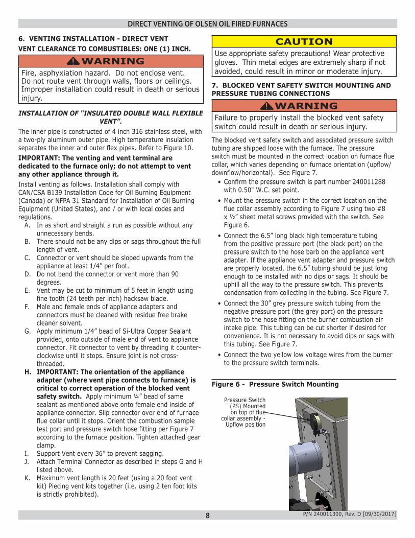
• Mount the pressure switch in the correct location on the flue collar assembly according to Figure 7 using two #8 x ½” sheet metal screws provided with the switch. See Figure 6.
• Connect the 6.5” long black high temperature tubing from the positive pressure port (the black port) on the pressure switch to the hose barb on the appliance vent adapter. If the appliance vent adapter and pressure switch are properly located, the 6.5” tubing should be just long enough to be installed with no dips or sags. It should be uphill all the way to the pressure switch. This prevents condensation from collecting in the tubing. See Figure 7.
• Connect the 30” grey pressure switch tubing from the negative pressure port (the grey port) on the pressure switch to the hose fitting on the burner combustion air intake pipe. This tubing can be cut shorter if desired for convenience. It is not necessary to avoid dips or sags with this tubing. See Figure 7.
• Connect the two yellow low voltage wires from the burner to the pressure switch terminals.
Figure 6 - Pressure Switch Mounting
6. VENTING INSTALLATION - DIRECT VENTVENT CLEARANCE TO COMBUSTIBLES: ONE (1) INCH.
WARNINGFire, asphyxiation hazard. Do not enclose vent. Do not route vent through walls, floors or ceilings. Improper installation could result in death or serious injury.
!
INSTALLATION OF "INSULATED DOUBLE WALL FLEXIBLE VENT”.
The inner pipe is constructed of 4 inch 316 stainless steel, with a two-ply aluminum outer pipe. High temperature insulation separates the inner and outer flex pipes. Refer to Figure 10. IMPORTANT: The venting and vent terminal are dedicated to the furnace only; do not attempt to vent any other appliance through it.Install venting as follows. Installation shall comply with CAN/CSA B139 Installation Code for Oil Burning Equipment (Canada) or NFPA 31 Standard for Installation of Oil Burning Equipment (United States), and / or with local codes and regulations.
A. In as short and straight a run as possible without any unnecessary bends.
B. There should not be any dips or sags throughout the full length of vent.
C. Connector or vent should be sloped upwards from the appliance at least 1/4” per foot.
D. Do not bend the connector or vent more than 90 degrees.
E. Vent may be cut to minimum of 5 feet in length using fine tooth (24 teeth per inch) hacksaw blade.
F. Male and female ends of appliance adapters and connectors must be cleaned with residue free brake cleaner solvent.
G. Apply minimum 1/4” bead of Si-Ultra Copper Sealant provided, onto outside of male end of vent to appliance connector. Fit connector to vent by threading it counter-clockwise until it stops. Ensure joint is not cross-threaded.
H. IMPORTANT: The orientation of the appliance adapter (where vent pipe connects to furnace) is critical to correct operation of the blocked vent safety switch. Apply minimum ¼” bead of same sealant as mentioned above onto female end inside of appliance connector. Slip connector over end of furnace flue collar until it stops. Orient the combustion sample test port and pressure switch hose fitting per Figure 7 according to the furnace position. Tighten attached gear clamp.
I. Support Vent every 36” to prevent sagging.J. Attach Terminal Connector as described in steps G and H
listed above.K. Maximum vent length is 20 feet (using a 20 foot vent
kit) Piecing vent kits together (i.e. using 2 ten foot kits is strictly prohibited).
DIRECT VENTING OF OLSEN OIL FIRED FURNACES
Pressure Switch(PS) Mounted on top of flue
collar assembly - Upflow position

9 P/N 240011300, Rev. D [09/30/2017]
DIRECT VENTING OF OLSEN OIL FIRED FURNACES
Figure 7 - Appliance Adapter Orientation, Pressure Switch Location, and Tubing Connections for Proper Blocked Vent Safety Switch Operation
240011289Appliance Adapter
Mounted on Flue Collar Assembly
Test Port On240011289Appliance Adapter
Pressure Switch(PS) Mounting Location on Flue Collar Assembly
Black Pressure Tubing To Appliance Adapter
Grey Pressure Tubing To Combustion Air Intake Collar
Combustion Air Intake Collar
Downflow Test Port at 9:00
Upflow Test Port at 12:00
PS
Horizontal Right
Test Port at 12:00
Horizontal Left
Test Port at 9:00
10 P/N 240011300, Rev. D [09/30/2017]
DIRECT VENTING OF OLSEN OIL FIRED FURNACES
8. OIL BURNER SET UP• Shut off electrical power to the furnace. • Install an oil pressure gauge to the pressure port on the oil
pump. • Set up the burner for initial firing as indicated in:
º Chart 1 for Beckett NX burners º Chart 2 for Riello 40BF burners
• Refer to oil burner instructions provided with furnace documents envelope for specific information concerning burner adjustment, operation and troubleshooting.
• See figure 8, or 9 as applicable for proper air adjustment technique.
• Restore electrical power to furnace. • Start the furnace and bleed all air from fuel oil lines. • Close purge valve and fire the unit. • Allow the furnace to warm up to normal operating
temperatures. During this time set the pump pressure in accordance with Chart 1 or 2 as applicable.
• Combustion must be checked with intake air piping connected for 100% outdoor combustion air to burner. Length of intake air piping and outside air temperature will affect the combustion readings.
º For Riello burners the standard burner cover must be in place on the burner to insure 100% outdoor air.
º For Beckett NX burners, the intake air pipe is configured such that 100% outdoor air is achieved either with or without optional burner cover.
• Determine the Desired CO2 Setpoint: º Combustion air temperature variations will affect how much air enters the burner. Colder air is denser, so contains more air per unit volume. More air enters the burner when the combustion air is cold. Combustion air temperature must be taken into consideration when setting up the burner to account for these variations.
º When the furnace has reached steady state (after approximately 10-15 minutes), remove the bolt from the test port in the appliance connector. Set the combustion air to obtain a TRACE of smoke.
º Using suitable combustion test instruments, measure the Trace Point CO2 at the test port.
º Calculate CO2 Setpoint A = Trace Point CO2 minus 1.5% and enter it here: Setpoint A: _______________EXAMPLE: Assume Trace Point CO2 = 13.0%Setpoint A = Trace Point CO2 minus 1.5% = 13.0% minus 1.5% = 11.5%
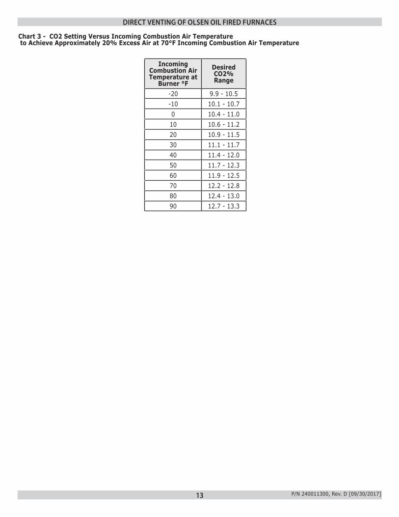
º Measure the incoming combustion air temperature. º Using Chart 3, determine Setpoint B for the measured incoming combustion air temperature (choose the midpoint of the range) and enter it here:Setpoint B: ________________
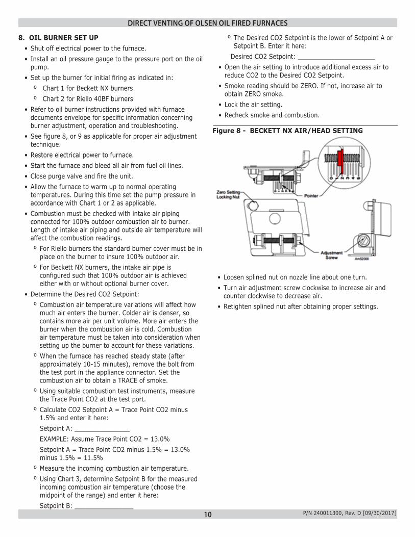
Figure 8 - BECKETT NX AIR/HEAD SETTING
• Loosen splined nut on nozzle line about one turn.• Turn air adjustment screw clockwise to increase air and
counter clockwise to decrease air.• Retighten splined nut after obtaining proper settings.
º The Desired CO2 Setpoint is the lower of Setpoint A or Setpoint B. Enter it here:
Desired CO2 Setpoint: _____________________• Open the air setting to introduce additional excess air to
reduce CO2 to the Desired CO2 Setpoint. • Smoke reading should be ZERO. If not, increase air to
obtain ZERO smoke. • Lock the air setting. • Recheck smoke and combustion.
11 P/N 240011300, Rev. D [09/30/2017]
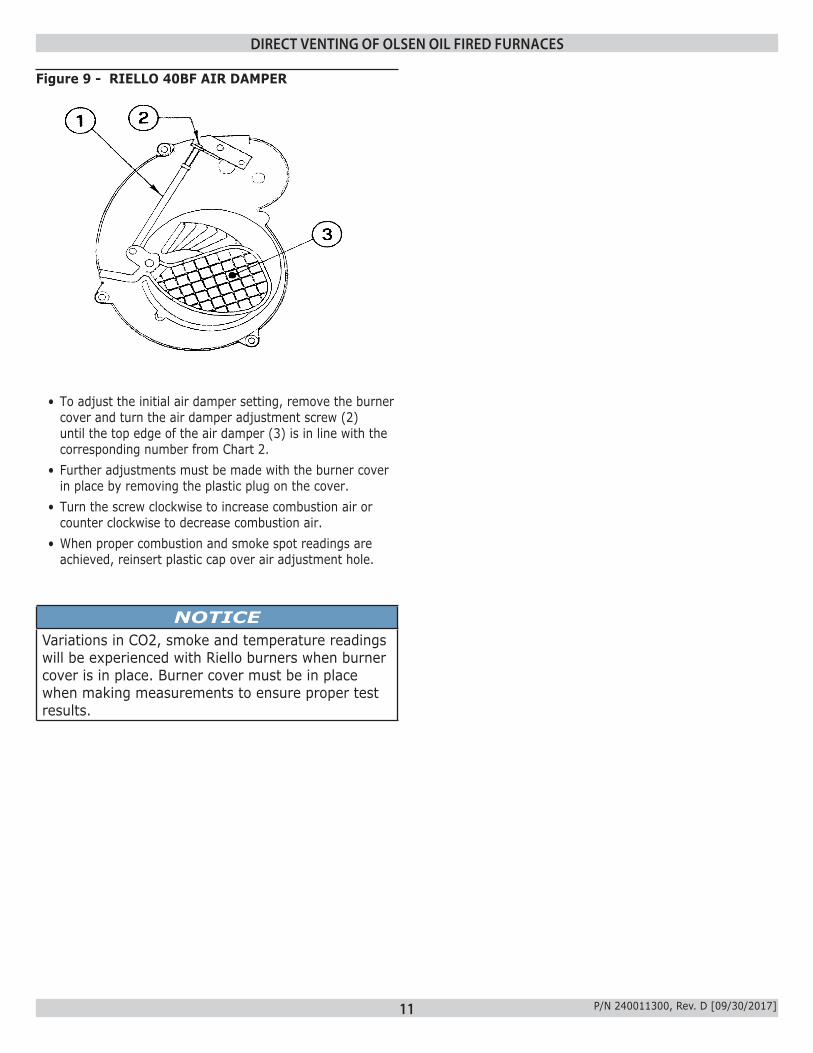
• To adjust the initial air damper setting, remove the burner cover and turn the air damper adjustment screw (2) until the top edge of the air damper (3) is in line with the corresponding number from Chart 2.
• Further adjustments must be made with the burner cover in place by removing the plastic plug on the cover.
• Turn the screw clockwise to increase combustion air or counter clockwise to decrease combustion air.
• When proper combustion and smoke spot readings are achieved, reinsert plastic cap over air adjustment hole.
Figure 9 - RIELLO 40BF AIR DAMPER
NOTICEVariations in CO2, smoke and temperature readings will be experienced with Riello burners when burner cover is in place. Burner cover must be in place when making measurements to ensure proper test results.
DIRECT VENTING OF OLSEN OIL FIRED FURNACES

12 P/N 240011300, Rev. D [09/30/2017]
DIRECT VENTING OF OLSEN OIL FIRED FURNACES
Beckett NX Series Oil Burners
(For use with direct vent units using outdoor combustion air only.)
Furnace Model Output [BTU/Hr]
Burner Model
Delavan Nozzle
Pump Pressure [PSIG]
Flow Rate [USGPH]
Low Firing Rate Baffle
Air Setting
UML65ANXU66,000 NX56LQ 0.50/60°W 140 0.55 Yes 3
UMLV65ANXUUML80ANXU
77,000 NX56LQ 0.50/60°W 175 0.65 Yes 3.25UMLV80ANXUUML90ANXU
88,000 NX56LQ 0.60/60°W 175 0.75 No * 3.25UMLV90ANXUUML100ANXU
99,000 NX56LQ 0.65/60°W 175 0.85 No * 3.75UMLV100ANXU* Burner is factory equipped with low firing rate baffle. Remove as shown for 0.75 and 0.85 USGPH firing rates.
Riello 40BF3/40BF5 Series Oil Burners(For use with direct vent units using outdoor combustion air only.)
Furnace Model Output [BTU/Hr]
Burner Model
Delavan Nozzle
Pump Pressure [PSIG]
Flow Rate [USGPH]
Turbulator Setting
Air Setting
UML65ARBU66,000 40BF3 0.50/90°B 125 0.55 0.0 4.25
UMLV65ARBUUML80ARBU
77,000 40BF3 0.55/80°B 140 0.65 1.0 5.25UMLV80ARBUUML90ARBU
88,000 40BF5 0.65/80°B 140 0.75 0.0 3.75UMLV90ARBUUML100ARBU
99,000 40BF5 0.75/80°B 130 0.85 0.0 4.25UMLV100ARBU
Chart 1 - Beckett NX Oil Burner Setup
Chart 2 - Riello 40BF Oil Burner Setup
Note: Riello 40BF3 burner is required for 0.55 and 0.65 USGPH firing rates. Riello 40BF5 burner is required for 0.75 and 0.85 USGPH firing rates.
13 P/N 240011300, Rev. D [09/30/2017]
DIRECT VENTING OF OLSEN OIL FIRED FURNACES
Incoming Combustion Air Temperature at
Burner °F
Desired CO2% Range
-20 9.9 - 10.5-10 10.1 - 10.70 10.4 - 11.010 10.6 - 11.220 10.9 - 11.530 11.1 - 11.740 11.4 - 12.050 11.7 - 12.360 11.9 - 12.570 12.2 - 12.880 12.4 - 13.090 12.7 - 13.3
Chart 3 - CO2 Setting Versus Incoming Combustion Air Temperature to Achieve Approximately 20% Excess Air at 70°F Incoming Combustion Air Temperature
14 P/N 240011300, Rev. D [09/30/2017]
DIRECT VENTING OF OLSEN OIL FIRED FURNACES
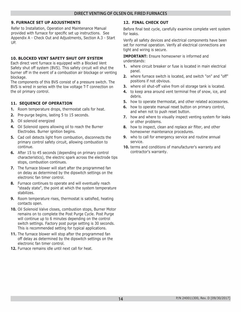
10. BLOCKED VENT SAFETY SHUT OFF SYSTEMEach direct vent furnace is equipped with a Blocked Vent Safety shut off system (BVS). This safety circuit will shut the burner off in the event of a combustion air blockage or venting blockage.The components of this BVS consist of a pressure switch. The BVS is wired in series with the low voltage T-T connection on the oil primary control.
11. SEQUENCE OF OPERATION 1. Room temperature drops, thermostat calls for heat.2. Pre-purge begins, lasting 5 to 15 seconds.3. Oil solenoid energized 4. Oil Solenoid opens allowing oil to reach the Burner
Electrodes. Burner ignition begins.5. Cad cell detects light from combustion, disconnects the
primary control safety circuit, allowing combustion to continue.
6. After 15 to 45 seconds (depending on primary control characteristics), the electric spark across the electrode tips stops, combustion continues.
7. The furnace blower will start after the programmed fan on delay as determined by the dipswitch settings on the electronic fan timer control.
8. Furnace continues to operate and will eventually reach "steady state", the point at which the system temperature stabilizes.
9. Room temperature rises, thermostat is satisfied, heating contacts open.
10. Oil Solenoid Valve closes, combustion stops, Burner Motor remains on to complete the Post Purge Cycle. Post Purge will continue up to 6 minutes depending on the control switch settings. Factory post purge setting is 30 seconds. This is recommended setting for typical applications.
11. The furnace blower will stop after the programmed fan off delay as determined by the dipswitch settings on the electronic fan timer control.
12. Furnace remains idle until next call for heat.
12. FINAL CHECK OUTBefore final test cycle, carefully examine complete vent system for leaks. Verify all safety devices and electrical components have been set for normal operation. Verify all electrical connections are tight and wiring is secure.IMPORTANT: Ensure homeowner is informed and understands:1. where circuit breaker or fuse is located in main electrical
panel.2. where furnace switch is located, and switch "on" and "off"
positions if not obvious.3. where oil shut-off valve from oil storage tank is located.4. to keep area around vent terminal free of snow, ice, and
debris.5. how to operate thermostat, and other related accessories.6. how to operate manual reset button on primary control,
and when not to push reset button.7. how and where to visually inspect venting system for leaks
or other problems.8. how to inspect, clean and replace air filter, and other
homeowner maintenance procedures.9. who to call for emergency service and routine annual
service.10. terms and conditions of manufacturer's warranty and
contractor's warranty.
9. FURNACE SET UP ADJUSTMENTSRefer to Installation, Operation and Maintenance Manual provided with furnace for specific set up instructions. See Appendix A - Check Out and Adjustments, Section A.3 - Start UP.

15 P/N 240011300, Rev. D [09/30/2017]
LE
GE
ND
/leg
en
de
FA
CT
OR
Y W
IRIN
G
fila
ge
a l'u
sin
e
FIE
LD
WIR
ING
fila
ge
au
ch
am
ps
TE
RM
INA
L P
RO
VID
ED
/
po
int d
e r
acco
rd fo
urn
i
GR
OU
ND
/Te
rre
TE
RM
INA
L N
OT
PR
OV
IDE
D/p
oin
t
de
ra
cco
rd n
on
-fo
urn
i
120 V
24 V
24 V
120 V
24
00
11
18
4 R
EV
D
BK
B
LA
CK
/noir
BL B
LU
E/b
leu
BR
B
RO
WN
/bru
n
GR
G
RE
EN
/vert
OR
O
RA
NG
E/o
range
RD
R
ED
/rouge
AU
XIL
IAR
Y L
IMIT
LIM
IT/lim
ite
LO
W S
PE
ED
FA
N S
WIT
CH
(P
SC
BLO
WE
R O
NLY
)
CA
P C
AP
AC
ITO
R/c
apaciteur
YL Y
ELLO
W/jaune
WH
W
HIT
E/b
lanc
GN
D G
RO
UN
D/T
err
e
VI V
IOLE
T/v
iole
t
BLO
CK
ED
VE
NT
SA
FE
TY
limite a
uxili
aire
AL
inte
rupte
ur
a b
asse v
itesse (
CF
P s
eule
ment de s
ouffla
nte
)FL
com
mande d
'ûpre
uve d
e s
ystè
me d
'ûvacuation b
loquû
BV
S
transfo
rmate
ur
d'a
llum
age
IGN
ITE
R/
I
soupappe
VA
LV
E/
V L1
(FU
SE
D D
ISC
ON
NE
CT
ON
HO
T L
EG
)P
OW
ER
SU
PP
LY
120 V
AC
60 H
Z
alim
enta
tion 1
20 V
AC
60H
z(d
isjo
incte
ur
avec fusib
le s
ur
le fil
d'a
limenta
tion)
CR
WY
G
THE
RM
OS
TAT
TH
ER
MO
ST
AT
CO
NN
EC
TIO
NS
/
raccord
e d
u therm
osta
t
YG
RW
C
1158-1
CO
NT
RO
L
BR
BR
CA
PW
HB
K
N (
CO
MM
ON
)
GN
D
YL
YL
BURNER
MOTOR
12
43
53
UNUSED
12
EAC
CONT
HEAT
COOL
67HUM
X CF
TR
AN
SF
OR
ME
R/
MH
I
31
25
4
HC
LM
L
N
WH
BK
BL
BR
WH
BK
VI
12
43
BK
WH
RD
RD
BL
12
0V
24
V
24
VC
OM
GR
BV
S
L
BL
OW
ER
ve
ntila
teu
rp
rin
cip
ale
IND
OO
R
mo
teu
rM
OT
OR
BU
RN
ER
MO
LE
X
CO
NN
EC
TO
R/
co
nn
ecte
ur
mo
lex
du
br�
leu
r
tra
nsfo
rma
teu
r
11
58
-1 / 1
16
8-1
CO
NTR
OL
L1
YL
2 4 7 5 9 6 3 8 10 1 12
11
BL
BR
BR
BR
CO
NT
RO
L B
OX
MO
LE
X C
ON
NE
CT
OR
Bo
îtie
r d
e c
om
ma
nd
e
du
co
nn
ecte
ur M
ole
x
AL
T-T
RD
RD
VI
WH
BK
RD
TH
ER
MO
ST
AT
CO
NN
EC
TIO
NS
/
raccord
e d
u therm
osta
t
THE
RM
OS
TAT
GY
/Y2
Y1
Y1
GY
/Y2
CR
WO
DH
WO
DH
RC
1168-1
CO
NT
RO
L
IND
OO
R
ve
ntila
teu
rp
rin
cip
ale
BL
OW
ER
MO
TO
Rm
ote
ur
1
EC
M
45
23
ventila
teur
a E
CM
(si dis
ponib
le)
EC
M M
OT
OR
(IF
AV
AIL
AB
LE
)
P1
1614
15
87
6
135
11
43
1210
9
21
5
13 1514
6 7
P1
8
16
1 2
9 10 12
3 4
11
CO
NT
RO
L
1168-1
120
VA
C
BK
NE
UT
WH
YL
56
JU
MP
ER
*
BK
65
34
21
BK W
H
BL
BR
CA
P
9 117 8
BR
BK
WHW
H
6321
53
0S
EC
L N
WH
mo
teu
rM
OT
OR
VB
L
RD
WH
RD
GY
YL
BL
AL
1009
12
BL
RD
/ 2
4V
BK
VI
TTBL
YL
RIE
LLO
BF
3 B
UR
NE
R/b
r�le
ur
(IF
AV
AIL
AB
LE
)/(s
i dis
ponib
le)
VI
BK
WH
L2 (
WH
ITE
)
IGN
ITE
R (
BLU
E/W
HIT
E)
(YE
LLO
W)
FL
AM
E S
EN
SO
Rso
nd
e a
fla
me
VI
BL
OR
WH BK
YL
YL
BE
CK
ET
T B
UR
NE
R/b
r�le
ur
mote
ur
MO
TO
R
V
I
BE
CK
ET
T O
IL
PR
IMA
RY
CO
NT
RO
L
L2 (
WH
ITE
)
L2 (
WH
ITE
)
VA
LV
E (
VIO
LE
T)
MO
TO
R (
OR
AN
GE
)
LIM
IT (
RE
D)
L1 (
BLA
CK
)
L2 (
WH
ITE
)
CA
D C
ELL
WH
WH
WH
TR
TW
12
43
56
TO
T-T
BL
YL
YL
TO
T-T
YL
BV
S
DIR
ECT
VEN
TIN
G W
IRIN
G D
IAG
RAM
DIRECT VENTING WIRING DIAGRAM

16 P/N 240011300, Rev. D [09/30/2017]
DIRECT VENTING OF OLSEN OIL FIRED FURNACES - VENTING COMPONENTS
Figure 10 - VENTING COMPONENTS

17 P/N 240011300, Rev. D [09/30/2017]
VENTING COMPONENTS/MATCHING GUIDE
Figure 11 - Z-FLEX VENTING COMPONENTS / MATCHING GUIDE
Also included with vent kits:Tube of Ultra Copper Sealant4" Vent Terminal Connector Part Number 240006914
Also included with burners, as applicable:Combustion Air Intake Collar, 4" Straight for Beckett burner Part Number 109005950Combustion Air Intake Collar, 3" Straight for Riello burner Part Number 109006030Combustion Air Intake Collar, 3" Elbow for Riello burner Part Number 3002333Combustion Air Intake Increaser, 3" x 4" for Riello burner Part Number 240011310
Figure 12 - DIRECT VENT PARTS IDENTIFICATION
5”
Also included with furnace:Blocked Vent Safety Switch (Pressure Switch) Part Number 240011288 (0.50" W.C. Set Point for use with Beckett and Riello Burners) 6.5" of Black Pressure Switch Tubing Part Number 3070530" Grey Pressure Switch Tubing Part Number 11344
Z-FLEX VENTING COMPONENTS MATCHING GUIDE
MODELITEMS INCLUDED WITH
FURNACEREQUIRED ITEMS ORDERED SEPARATELY FIELD
SUPPLIED COMPONENTS
TEMINATION STD OR RISER YOUR CHOICE OFITEM P/N ITEM P/N ITEM P/N
UML5" X 4"
APPLIANCE ADAPTER
240011289
OIL VENT TERMINAL 28972 4" X 10' VENT KIT 240006909
COMBUSTION AIR PIPINGOR 4" X 15' VENT KIT 240006910
OIL VENT RISER 29231 4" X 20' VENT KIT 240006911

18 P/N 240011300, Rev. D [09/30/2017]
DIRECT VENTING OF OLSEN OIL FIRED FURNACES
EXTERNAL ACTION APPLIANCE RESPONSE
Power applied to 7505P control Internal safety check conducted. If no light or flame is detected and all internal conditions are correct, control enters idle mode.
Thermostat calls for heat.
1. Contacts between T and T on 7505P are closed.2. Primary Control Safety period (4 seconds) internal and external check for flame or light. If
flame is detected, control remains in idle mode.3. When flame is not present, 7505P will apply power to the burner motor and igniter, complete a
15 second valve on delay period and then apply power to the oil valve circuit.4. Enters the trial for ignition period.
A. Monitors burner for flame.B. When flame is not detected:
i. Enters lockout mode after 15 seconds.ii. Shuts off valve, igniter and burner motor.iii. Flashes indicator light at 1 Hz (½ second on, ½ second off).iv. Depress reset button to return to power up sequence.
C. When flame is detected, Carry-Over period begins: 5. Enters 10-second Ignition Carry-Over period.
A. Turns on indicator lightB. If flame is lost and lockout time has not expired, THE PRIMARY CONTROL returns to trial for
Ignition period.C. If flame is lost and lockout time has expired, THE PRIMARY CONTROL enters Recycle Mode.
6. Carry-over time expires and igniter turns off.7. Enters a run mode:
A. Flame is monitored until call for heat ends or flame is lost. If flame is lost: i. Control enters Recycle Mode. ii. Recycle time starts (60 seconds). iii. Burner and valve are turned off. iv. Red Light FlashSafety Lockout Red Light SolidHard Lockout v. Returns to Idle mode at end of Recycle mode.
Call for heat is satisfied.
1. Oil valve circuit is de-energized and valve shuts off.2. Burner motor runs for selected burner motor-off delay.3. Burner motor turns off.
Returns to Idle mode
Reset button pushed two times without device completing a call for heat.
1. Enters restricted Hard Lockout.2. Indicator light on continuously 3. Reset device by pressing and holding reset button for a minimum of 15 seconds. (Yellow Light
Turns ON)
Pressure switch contacts open and cause burner to recycle
In the event of vent or combustion air intake blockage, the blocked vent safety switch (pressure switch) contacts will open, opening the contacts between T and T on the 7505P primary control, as if ending the call for heat. Once the post purge period (burner motor off delay) ends, the burner motor will shut off and the pressure switch contacts will re-close, again closing the T-T contacts and starting the burner motor. If the vent or combustion air intake blockage remains, the pressure switch contacts will open again once the burner motor is running, and shut the burner motor off. Continuous cycling of this type indicates vent or combustion air intake blockage.
Figure 13 - BECKETT BURNER WITH BLOCKED VENT SAFETY (BVS) OPERATION
19 P/N 240011300, Rev. D [09/30/2017]
DIRECT VENTING OF OLSEN OIL FIRED FURNACES
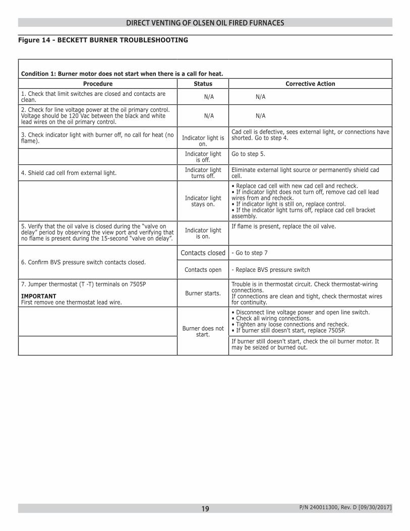
Condition 1: Burner motor does not start when there is a call for heat.Procedure Status Corrective Action
1. Check that limit switches are closed and contacts are clean. N/A N/A
2. Check for line voltage power at the oil primary control. Voltage should be 120 Vac between the black and white lead wires on the oil primary control.
N/A N/A
3. Check indicator light with burner off, no call for heat (no flame).
Indicator light is
on.
Cad cell is defective, sees external light, or connections have shorted. Go to step 4.
Indicator light is off.
Go to step 5.
4. Shield cad cell from external light. Indicator light turns off.
Eliminate external light source or permanently shield cad cell.
Indicator light stays on.
• Replace cad cell with new cad cell and recheck.• If indicator light does not turn off, remove cad cell lead wires from and recheck.• If indicator light is still on, replace control.• If the indicator light turns off, replace cad cell bracket assembly.
5. Verify that the oil valve is closed during the “valve on delay” period by observing the view port and verifying that no flame is present during the 15-second “valve on delay”.
Indicator light is on.
If flame is present, replace the oil valve.
6. Confirm BVS pressure switch contacts closed.Contacts closed - Go to step 7
Contacts open - Replace BVS pressure switch
7. Jumper thermostat (T -T) terminals on 7505P
IMPORTANTFirst remove one thermostat lead wire.
Burner starts.Trouble is in thermostat circuit. Check thermostat-wiring connections.If connections are clean and tight, check thermostat wires for continuity.
Burner does not start.
• Disconnect line voltage power and open line switch.• Check all wiring connections.• Tighten any loose connections and recheck.• If burner still doesn't start, replace 7505P.
If burner still doesn't start, check the oil burner motor. It may be seized or burned out.
Figure 14 - BECKETT BURNER TROUBLESHOOTING

20 P/N 240011300, Rev. D [09/30/2017]
Condition 2: Burner starts then locks out on safety with indicator light flashing at 1/2 second on, 1/2 second off.
Procedure Status Corrective Action
1. Reset oil primary control by pushing in and releasing red reset button. Flash - 1 sec. / Solid - 1 sec.
Indicator light stops flashing.
Go to Step 2.
Indicator light continues to flash at 1/2 second on, 1/2 second off rate.
Verify that the control is not in restricted mode. (See notes at end of this table.). If not in restricted mode, replace 7505P
2. Listen for spark after burner turns on (after 2 second delay).
Ignition is off Spark igniter could be defective. Check for line voltage at igniter terminals. If line voltage is present, replace 7505P.
Ignition is on. Go to Step 3.
Ignition is on but no oil is being sprayed into
the combustion chamber.
Wait for “Valve ON” delay to complete.1. Check oil supply.4. Check oil line valve.5. Check for filter blockage or seized oil pump.
3. Check indicator light after flame is established, but before oil primary control locks out.
Indicator light is on until the control locks
out and starts flashing during
lockout.
Replace 7505P
Indicator light stays off. Go to step 4.
4. Check cad cell sighting for view of flame. a. Disconnect line voltage power and open line switch. b. Unplug cad cell and clean cad cell face with soft cloth. Check sighting for clear view of flame. Replace cad cell in socket. c. Reconnect line voltage power and close line switch. d. Start burner.
Burner locks out Go to step 5.
Burner keeps running. System is OK.
5. Check cad cell. a. Disconnect line voltage power and open line switch. b. Remove existing cad cell and replace with new cad cell. c. Disconnect all wires from thermostat terminals to ensure that there is no call for heat. d. Reconnect line voltage power and close line switch. e. Expose new cad cell to bright light such as a flashlight.
Indicator light is on. Remount control onto burner housing, go to step 6.
Indicator light is off. System is OK.
6. Check cad cell bracket assembly. a. Disconnect line voltage power and open line switch. b. Remove cad cell wires from quick connect connectors on the R7505P and leave control lead wires open. c. Apply power to device. d. Place jumper across cad cell terminals after
Indicator light is on. Replace CAD cell bracket assembly.
Indicator light is off. Replace 7505P
DIRECT VENTING OF OLSEN OIL FIRED FURNACES
NOTE: Hard Lockout : In order to limit the accumulation of unburned oil in the combustion chamber, the control can be reset only 5 times, after which, the control locks out. The reset count returns to zero each time a call for heat is successfully completed.To reset from Hard Lockout: press and hold the reset button for 15 seconds. When the Yellow LED flashes turns on, the device has reset.
NOTE: Disable function: Pressing and holding the reset button will disable all functions until the button is released. The burner will restart at the beginning of the normal heat cycle on SAFETY CHECK.
Figure 14 - BECKETT BURNER TROUBLESHOOTING - continued
Condition 3: Burner motor continuously cycles on and off without trying to light burner.
- Blocked vent safety switch (pressure switch) contacts opening each time burner motor starts - Check venting for blockage - Check combustion air intake air pipe for blockage - Check pressure switch hoses for possible obstruction

21 P/N 240011300, Rev. D [09/30/2017]
EXTERNAL ACTION APPLIANCE RESPONSE
Thermostat calls for heat.
1. Contacts between T and T on oil burner primary control are closed.2. Burner enters pre-purge.3. After pre-purge, oil valve is energized and burner lights off.4. Burner operates in run mode.
Call for heat is satisfied.1. Oil valve circuit is de-energized and valve shuts off.2. Burner motor runs for duration of burner motor-off delay.3. Burner motor turns off.
Pressure switch contacts open and cause burner to re-cycle
In the event of vent or combustion air intake blockage, the blocked vent safety switch (pressure switch) contacts will open, opening the contacts between T and T on the oil burner primary control, as if ending the call for heat. Once the post purge period (burner motor off delay) ends, the burner motor will shut off and the pressure switch contacts will re-close, again closing the T-T contacts as if calling for heat and starting the burner motor as described above. If the vent or combustion air intake blockage remains, the pressure switch contacts will open again once the burner motor is running, and shut the burner motor off. Continuous cycling of this type indicates vent or combustion air intake blockage.
DIRECT VENTING OF OLSEN OIL FIRED FURNACES
Figure 15 - RIELLO 40BF With BLOCKED VENT SAFETY (BVS) OPERATION

22 P/N 240011300, Rev. D [09/30/2017]
Condition: Thermostat is calling for heat. Burner is not running.Problem Possible Cause Remedy
1. Reset control box.Burner starts. Go to step #4.Burner does not start Go to step #2
2. Test for 120 Vac supply at sub-base between L (P) & N or terminals #3 and #5.
120 Vac present. Go to step #3
No voltage• Check system fuse, breaker or ensure service switch is ON.• Verify all limits are closed.• If using switching relay, verify 24 Vac at T-T.
3. Confirm BVS pressure switch contacts closed.
Contacts Closed Go to step #4
Contacts Open Replace BVS
4. Turn off power supply- Remove control box and jumper terminals #5 and #6. Restore power.
Motor runs.
• Verify reduced voltage (42-52 Vac) between terminals #3 and #7.• Ensure good contact between control box spades and sub-base terminals.• Defective control box/ Replace.
Motor does not run.
• Verify electrical connections.• Check for seized pump, motor, or fan against housing.• Defective motor capacitor.• Thermal overload (Hot motor).
5. Burner Starts
Burner stays in Pre-purge.
• Faulty CAD cell or seeing light before trial for ignition.• Coil wires on terminals #1 and #2 or #1 and #8 reversed.• Open coil circuit; terminals #2 and #8.• Open coil circuit; terminal #1• Defective 42-52 Vac supply, terminals #3 and #7.• Defective control box/ Replace
Burner continues to purge and light off with immediate flame dropout.
• Metal yoke for coil missing.• Coil wire #2 and #8 reversed.• Low resistance of coil holding circuit, terminals #1 and #2, (1350 ohms ± 10%)..• Verify BVS pressure switch is remaining closed upon light off.
Burner locks out after trial for ignition.
• Low resistance or no contact on starting circuit of coil, terminals #2 and #8. (1.3-ohm ± %)• No oil supply- tank empty, valve closed, dirty filter, damaged supply lines.• Defective or dirty oil valve stem, nozzle, or pump strainer.• Broken pump drive key, defective pump or no oil pressure.• Ignition electrodes shorted, cracked porcelain.• Burner motor not up to speed.• Excessive draft over fire.• Defective control box/ Replace.
6. Burner motor continuously cycles on and off without trying to light the burner.
Blocked Vent Safety Switch (Pressure Switch) Opening
• Check venting for blockage• Check combustion air intake pipe for blockage• Check pressure switch operation. Confirm
contacts closed when furnace not running. • Check pressure switch tubes for possible
obstruction
DIRECT VENTING OF OLSEN OIL FIRED FURNACES
Figure 16 - RIELLO 40BF BURNER TROUBLESHOOTING

23 P/N 240011300, Rev. D [09/30/2017]
DIRECT VENTING OF OLSEN OIL FIRED FURNACES
HOMEOWNER’S REFERENCE TABLE
Model No.Serial No.Date InstalledContractorContact
Address
Postal Code
Telephone No.After Hours No.FUEL SUPPLIERFuel Oil SupplierContactTelephone No.After Hours No.IF DIFFERENT FROM INSTALLATION CONTRACTOR:Service Tech.Telephone No.After Hours No.