UML (Unified Modeling Language )
50
UML (Unified Modeling Language) Prof Hyoung-Joo Kim OOPSLA Lab. School of Computer Science and Engineeri ng Seoul National University
description
UML (Unified Modeling Language ). Prof Hyoung-Joo Kim OOPSLA Lab. School of Computer Science and Engineering Seoul National University. Contents. Introduction Software Development Object-Oriented Analysis Object-Oriented Design Summary. Introduction. UML? - PowerPoint PPT Presentation
Transcript of UML (Unified Modeling Language )

UML(Unified Modeling Language)
Prof Hyoung-Joo Kim
OOPSLA Lab.
School of Computer Science and Engineering
Seoul National University
2
Contents Introduction Software Development Object-Oriented Analysis Object-Oriented Design Summary
3
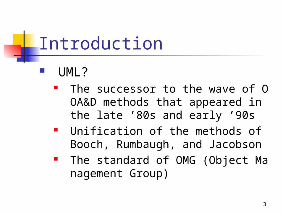
Introduction UML?
The successor to the wave of OOA&D methods that appeared in the late ’80s and early ’90s
Unification of the methods of Booch, Rumbaugh, and Jacobson
The standard of OMG (Object Management Group)
4
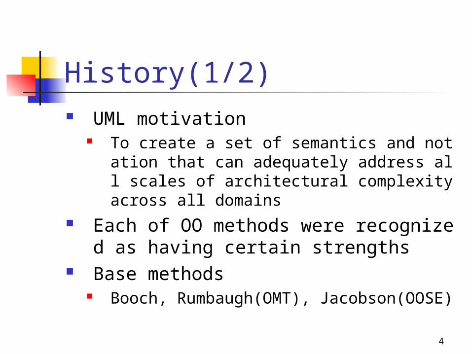
History(1/2) UML motivation
To create a set of semantics and notation that can adequately address all scales of architectural complexity across all domains
Each of OO methods were recognized as having certain strengths
Base methods Booch, Rumbaugh(OMT), Jacobson(OOSE)
5
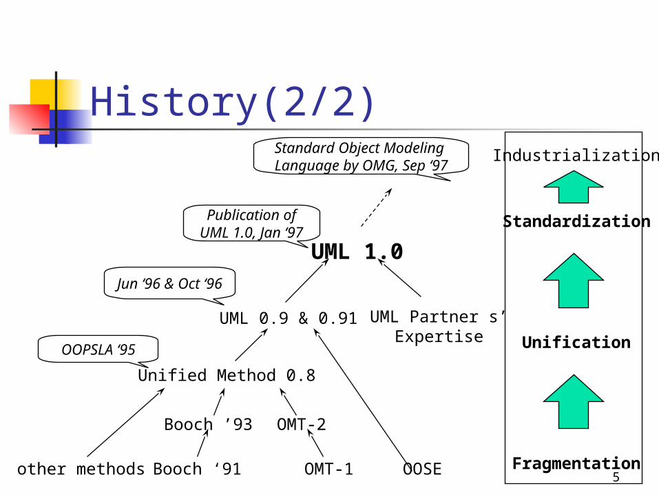
History(2/2)
other methods
UML 1.0
UML 0.9 & 0.91
Unified Method 0.8
Booch ’93 OMT-2
Booch ‘91 OMT-1 OOSE
UML Partner s’Expertise
Fragmentation
Unification
Standardization
Industrialization
Publication ofUML 1.0, Jan ‘97
Jun ‘96 & Oct ‘96
OOPSLA ‘95
Standard Object Modeling Language by OMG, Sep ‘97
6
Scope of the UML(1/2) Language for specifying constructing, visualizin
g, and documenting the artifacts of a software-intensive system
Fusing the concepts of Booch, OMT, and OOSE Envelop of what can be done with existing meth
ods Standard object modeling language adopted by
OMG, Sep., 1997
7
Scope of the UML(2/2) Object-Oriented Analysis
Use Case diagram Object interaction diagram Class diagram State diagram Activity diagram
Object-Oriented Design Process diagram Architecture diagram Deployment diagram
8
Comparing to Others(1/2) Not a radical departure from Booch, OMT, and
OOSE Legitimate successor to all three methods More expressive yet cleaner and more uniform Value in moving to the UML
It will allow projects to model things they could not have done before
It removes the unnecessary differences in notation and terminology
9
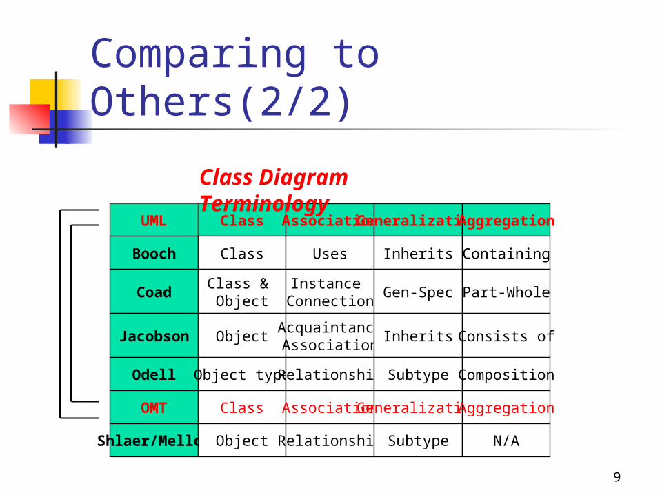
Comparing to Others(2/2)
UML Class Association Generalization Aggregation
Booch Class Uses Inherits Containing
CoadClass & Object
Instance Connection
Gen-Spec Part-Whole
Jacobson ObjectAcquaintanceAssociation
Inherits Consists of
Odell Object type Relationship Subtype Composition
OMT Class Association Generalization Aggregation
Shlaer/Mellor Object Relationship Subtype N/A
Class Diagram Terminology

10
Contents Introduction Software Development Object-Oriented Analysis Object-Oriented Design Summary
11
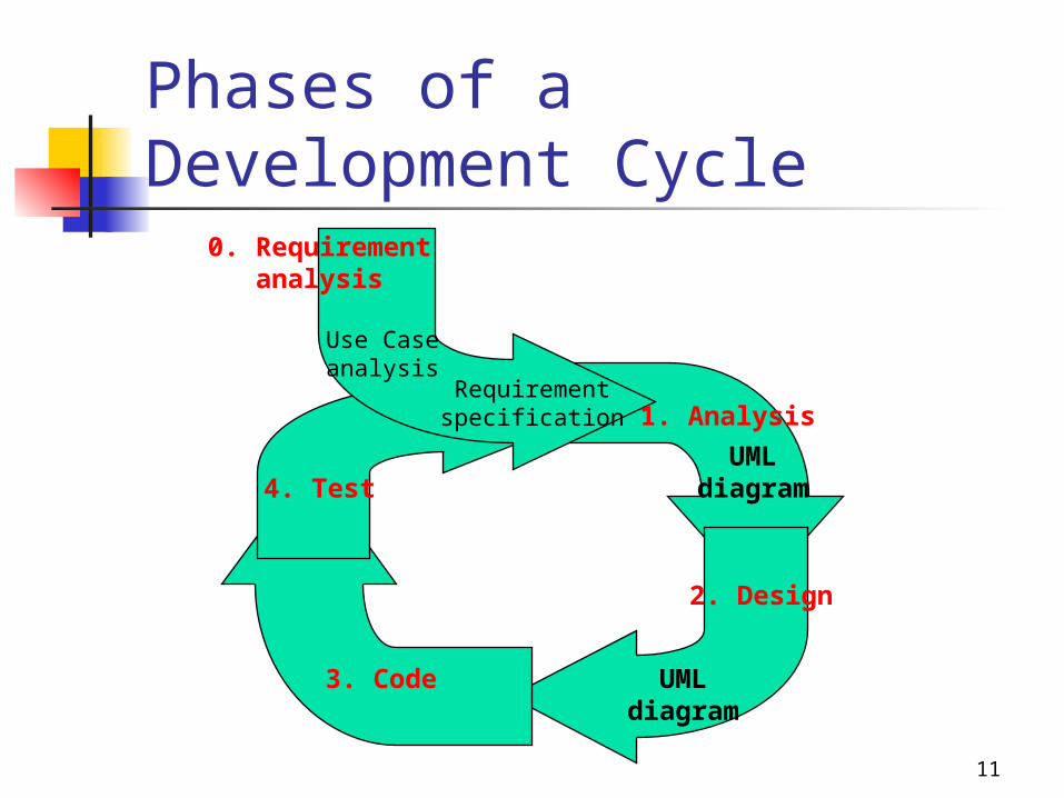
Phases of a Development Cycle0. Requirement
analysis
1. Analysis
2. Design
3. Code
4. Test
UMLdiagram
UMLdiagram
Use Caseanalysis
Requirementspecification
12
Phase of Development Requirement Analysis Analysis Design Code Test
13
Contents Introduction Software Development Object-Oriented Analysis Object-Oriented Design Summary
14
OO Analysis
Phase 1. Use Case Modeling
Phase 2. Class Finding & Refinement
Phase 3. Object Finding
Phase 4. Class Relationship
Phase 5. Class Specification
Phase 6. Analysis Refinement
15
OOA Phase 1. Use Case Modeling Introduced by Jacobson(1994) Use Case modeling by user requirement Relationship among actors and Use Cases Actors carry out Use Cases Use Case is a typical interaction between a user
and a computer system <<extends>> relationship : similar but do a bit more <<uses>> relationship : a chunk of behavior similar
across more than one use case
16
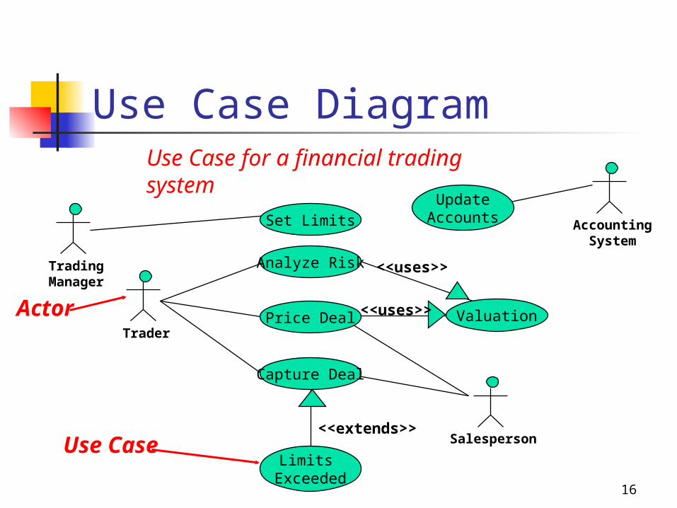
Use Case Diagram
Trading Manager
Set Limits
Capture Deal
Trader
Limits Exceeded
Valuation
Salesperson
Price Deal
Analyze Risk
UpdateAccounts Accounting
System
<<uses>>
<<uses>>
Use Case
Actor
<<extends>>
Use Case for a financial trading system
17
OOA Phase 2. Class Finding & Refinement
For each Use Case, finding classes Class Finding
Class Diagram Class Refinement
Remove redundant Name same, semantics different
aaa 18
Class The name of a class has scope within the
package in which it is declared and the name must be unique (among class names) within its package
References Show a reference to a class defined in another
package Package-name::class-name

19
Class Diagram Showing the static structure of the system A graph of modeling elements shown on a
two-dimensional surface A collection of (static) declarative model e
lements, such as classes, types, and their relationships, connected as a graph to each other and to their contents
20
Type A type is descriptor for objects with abstract
state, concrete external operation specification, and no operation implementations
Classes implement types Shown as a stereotype of a class symbol with the
stereotype <<type>> May contain lists of abstract attributes and of
operations May contain a context and specifications of its
operations accordingly
21
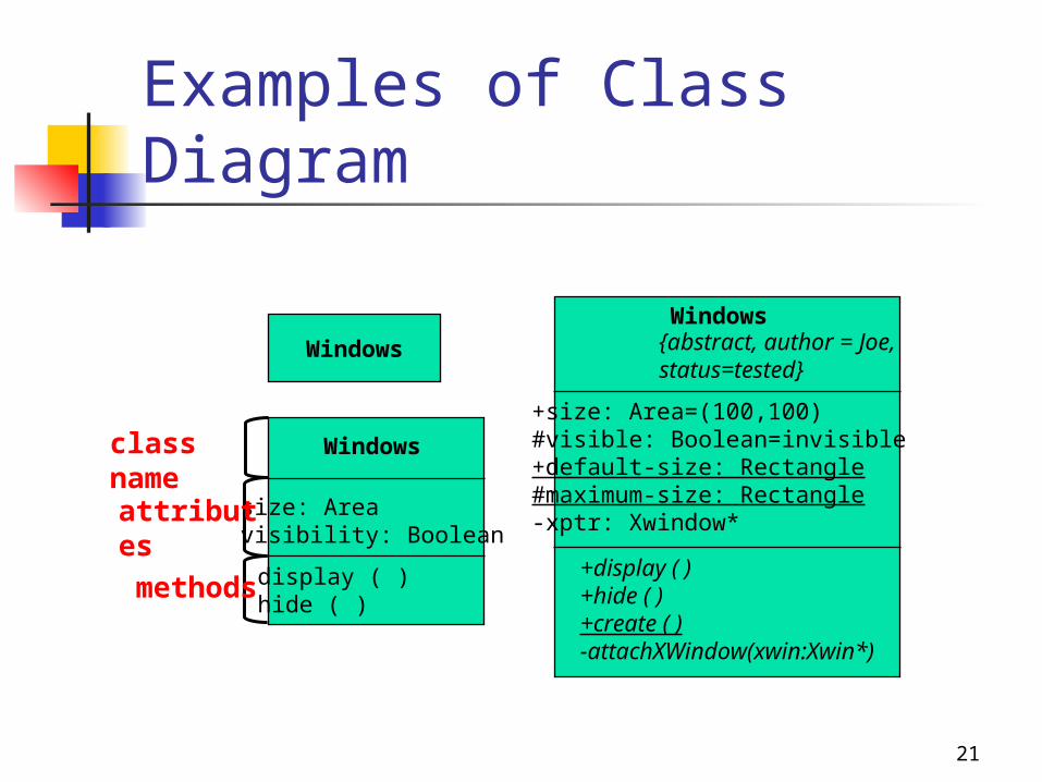
Examples of Class Diagram
Windows
Windows
size: Areavisibility: Boolean
display ( )hide ( )
Windows{abstract, author = Joe,status=tested}
+size: Area=(100,100)#visible: Boolean=invisible+default-size: Rectangle#maximum-size: Rectangle-xptr: Xwindow*
+display ( )+hide ( )+create ( )-attachXWindow(xwin:Xwin*)
attributes
methods
class name
22
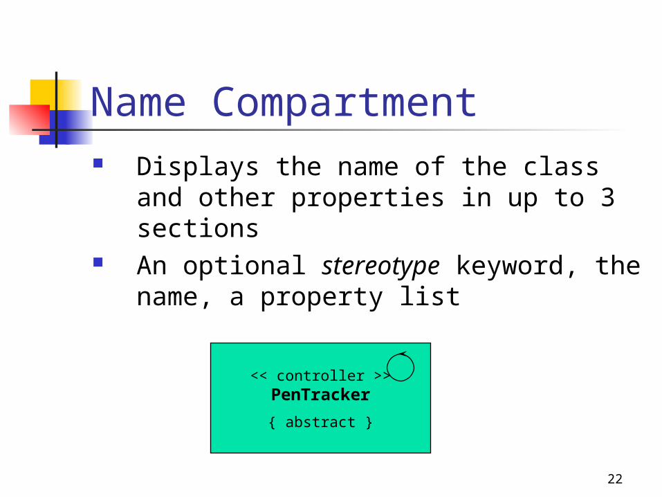
Name Compartment Displays the name of the class and other
properties in up to 3 sections An optional stereotype keyword, the name, a
property list
<< controller >>PenTracker
{ abstract }
23
OOA Phase 3. Object Finding
For each class, finding objects, and making object interaction diagram
Sequence Diagram Collaboration Diagram
Finding messages within objects
24
Object Diagram A graph of instances Static object diagram is an instance of a class dia
gram Dynamic object diagram shows the detailed state
of a system over some period of time Class diagrams can contain objects, so a class di
agram with objects and no classes is an “object diagram”
25
Sequence Diagram(1/2) Showing an interaction arranged in time s
equence Showing the explicit sequence of message
s Better for real-time specifications and for
complex scenarios
26
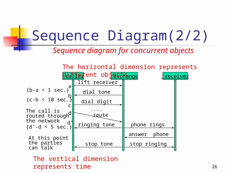
Sequence Diagram(2/2)
:caller :exchange :receiver
a
b
c
d
d’
lift receiver
dial tone
dial digit
....route
phone rings
answer phone
stop ringingstop tone
ringing tone
{b-a < 1 sec.}
{c-b < 10 sec.}
The call isrouted throughthe network{d’-d < 5 sec.}
At this pointthe partiescan talk
The horizontal dimension represents different objects
The vertical dimension represents time
Sequence diagram for concurrent objects
27
Collaboration Diagram(1/2) Showing the relationships among objects Better for understanding all of the effects
on a given object and for procedural design
Showing an interaction organized around the objects in the interaction and their links to each other
Not showing time as a separate dimension
28
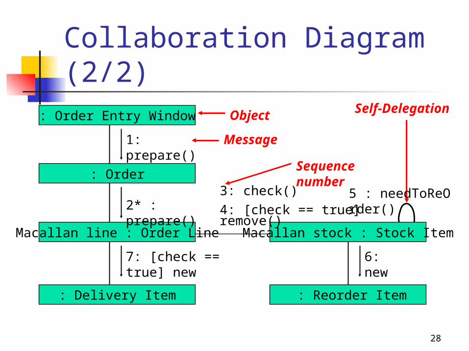
Collaboration Diagram(2/2): Order Entry Window
: Order
Macallan line : Order Line
: Delivery Item
Macallan stock : Stock Item
: Reorder Item
Object
1: prepare()
2* : prepare()
7: [check == true] new
3: check()
4: [check == true] remove()
6: new
Message
Sequence number
Self-Delegation
5 : needToReOrder()
29
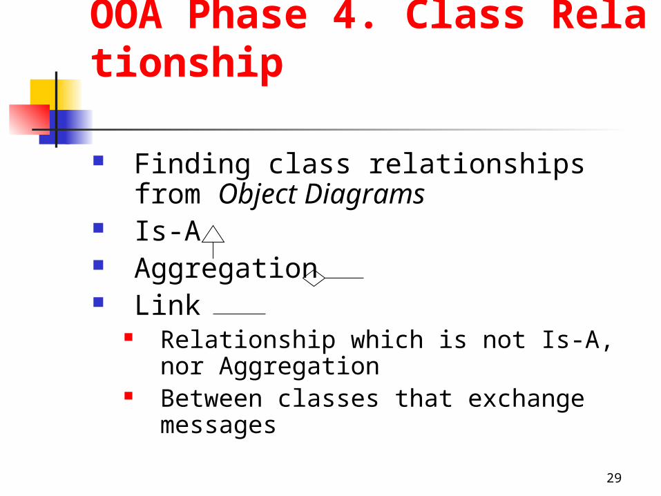
OOA Phase 4. Class Relationship
Finding class relationships from Object Diagrams
Is-A Aggregation Link
Relationship which is not Is-A, nor Aggregation
Between classes that exchange messages
30
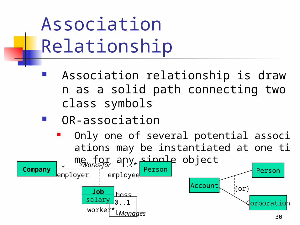
Association Relationship Association relationship is drawn as a solid path
connecting two class symbols OR-association
Only one of several potential associations may be instantiated at one time for any single object
Company Person* Works-for 1..*
employer employee
Jobsalary
boss
Manages
0..1worker *
Account
Person
Corporation
{or}
31
Aggregation & Composition Aggregation
Part of relationship Composition Relationship
Form of aggregation with strong ownership and coincident lifetime of part with the whole
The multiplicity of the aggregate end may not exceed one
32
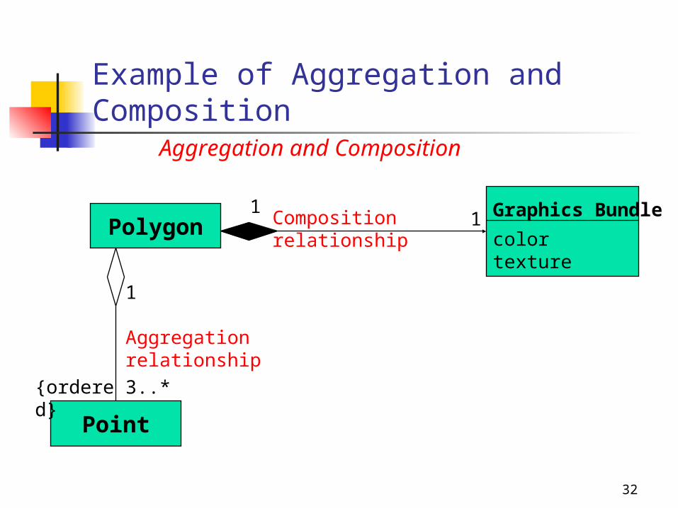
Example of Aggregation and Composition
Graphics Bundle
colortexture
Polygon
Point
{ordered} 3..*
1
11
Aggregation relationship
Composition relationship
Aggregation and Composition
33
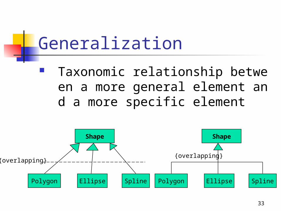
Generalization Taxonomic relationship between a more g
eneral element and a more specific element
Shape
Polygon Ellipse Spline
{overlapping}
Shape
Polygon Ellipse Spline
{overlapping}
34
OOA Phase 5. Class Specification
Attribute Behavior
By object interaction diagrams Operation
35
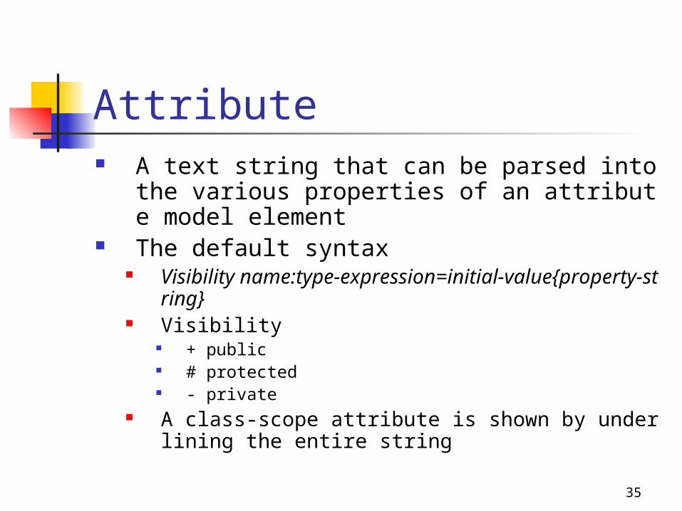
Attribute A text string that can be parsed into the various
properties of an attribute model element The default syntax
Visibility name:type-expression=initial-value{property-string}
Visibility + public # protected - private
A class-scope attribute is shown by underlining the entire string
36
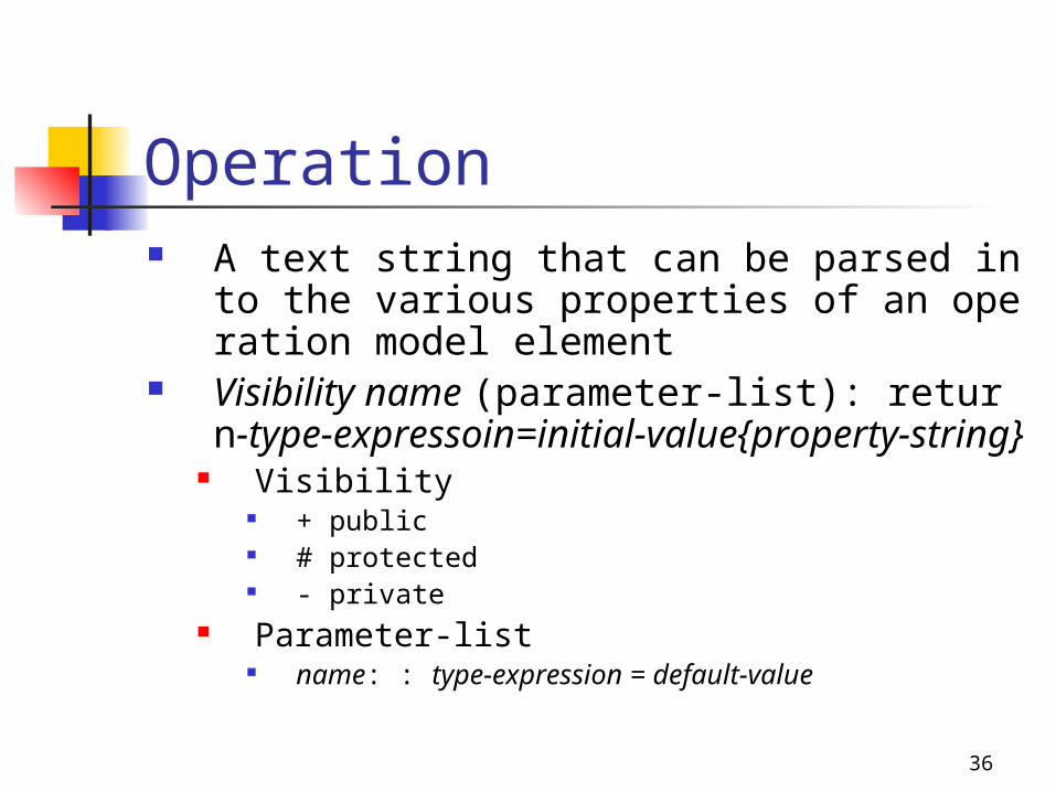
Operation A text string that can be parsed into the various
properties of an operation model element Visibility name (parameter-list): return-type-expr
essoin=initial-value{property-string} Visibility
+ public # protected - private
Parameter-list name: : type-expression = default-value

37
Examples of Attributes and Operations
Windows
Windows
size: Areavisibility: Boolean
display ( )hide ( )
Windows{abstract, author = Joe,status=tested}
+size: Area=(100,100)#visible: Boolean=invisible+default-size: Rectangle#maximum-size: Rectangle-xptr: Xwindow*
+display ( )+hide ( )+create ( )-attachXWindow(xwin:Xwin*)
attributes
methods
class name
38
OOA Phase 6. Analysis Refinement
Review all processes of analysis
39
Other UML Diagrams By user needs State Diagram Activity Diagram
40
State Diagram(1/2) A familiar technique to describe the
behavior of a system Describe all the possible states a particular
object can get into and how the object’s state changes as a result of events
Drawn for a single class to show the lifetime behavior of a single object
41
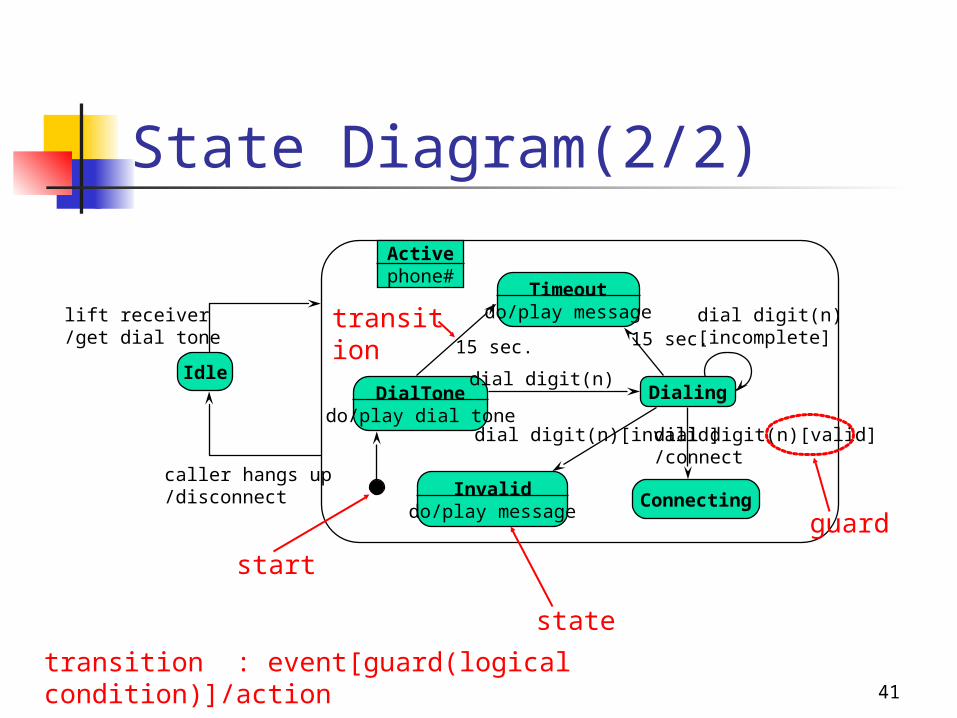
State Diagram(2/2)
Activephone#
Timeoutdo/play message
DialTonedo/play dial tone
Dialing
Invaliddo/play message
Connecting
Idle
lift receiver/get dial tone
caller hangs up/disconnect
15 sec. 15 sec.dial digit(n)[incomplete]
dial digit(n)
dial digit(n)[invalid] dial digit(n)[valid]/connect
state
transition
guard
transition : event[guard(logical condition)]/action
start
42
Activity Diagram(1/2) A special case of a state diagram in which all of
the states are action states and in which all of the transitions are triggered by completion of the actions in the source states
Use activity diagrams in situations where all or most of the events represent the completion of internally-generated actions
Use ordinary state diagrams in situations where asynchronous events occur
43
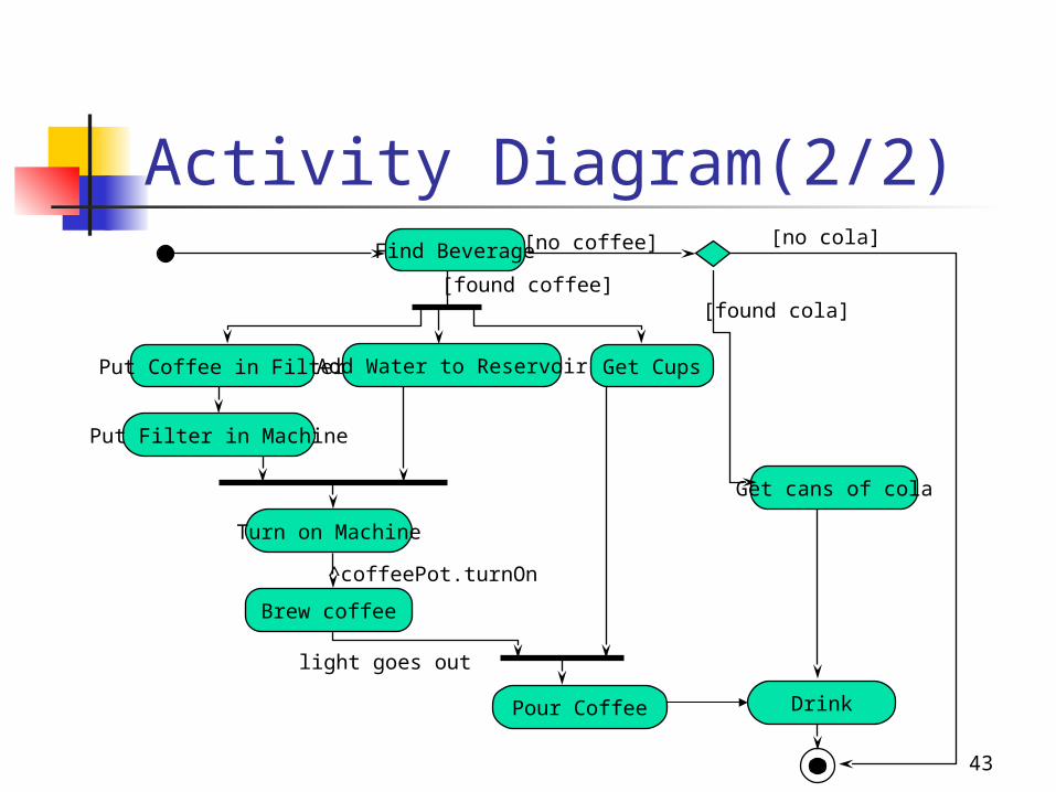
Activity Diagram(2/2)
Find Beverage
Put Coffee in Filter Add Water to Reservoir Get Cups
Put Filter in Machine
Turn on Machine
Brew coffee
Pour Coffee
Get cans of cola
Drink
[no coffee]
[found coffee]
[no cola]
[found cola]
^coffeePot.turnOn
light goes out
44
Contents Introduction Software Development Object-Oriented Analysis Object-Oriented Design Summary
45
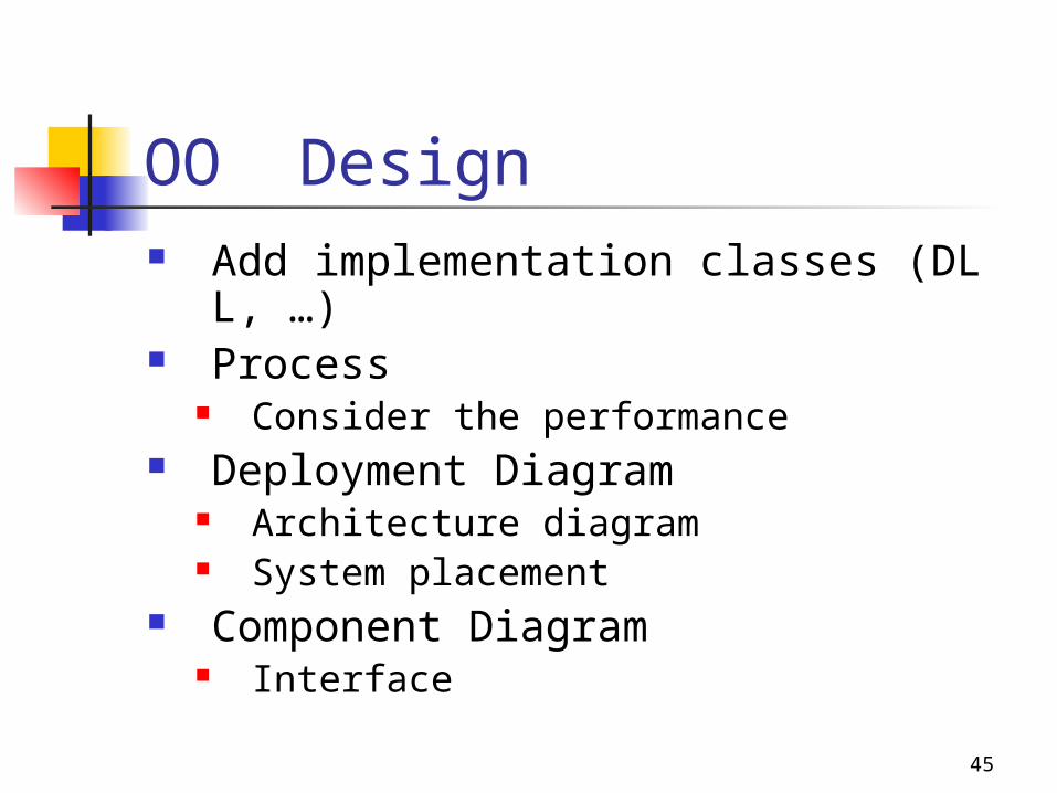
OO Design Add implementation classes (DLL, …) Process
Consider the performance Deployment Diagram
Architecture diagram System placement
Component Diagram Interface
46
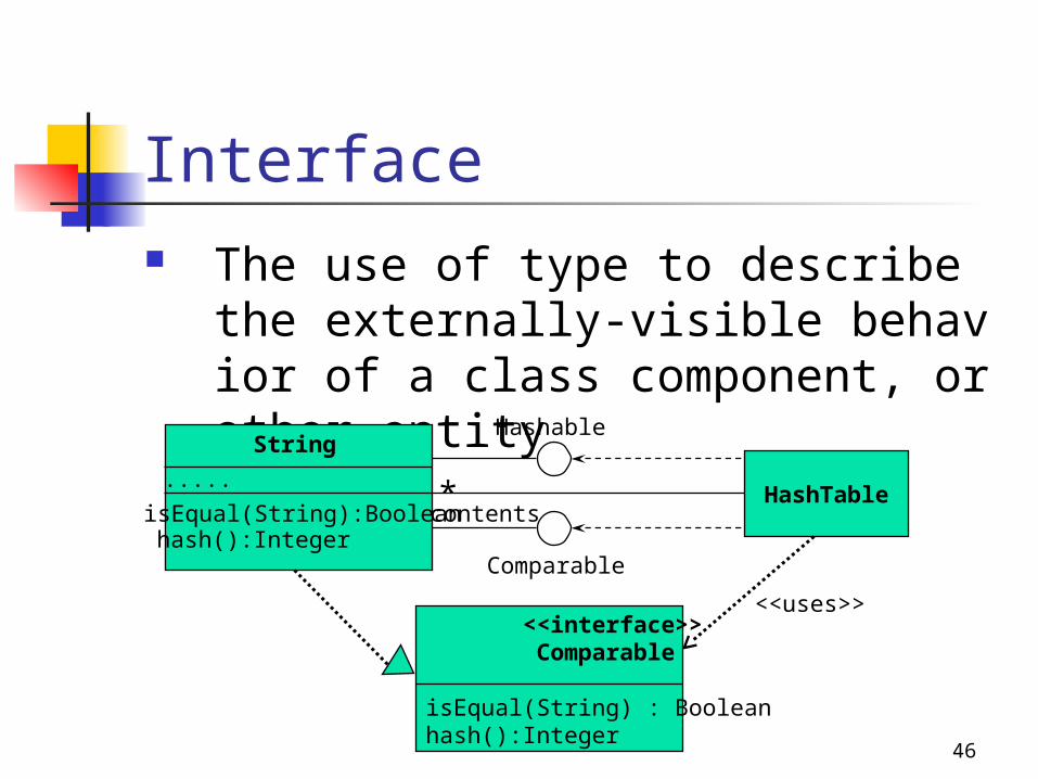
Interface The use of type to describe the externally-
visible behavior of a class component, or other entity
String
.....
isEqual(String):Booleanhash():Integer
HashTable*contents
Hashable
Comparable
<<interface>> Comparable
isEqual(String) : Booleanhash():Integer
<<uses>>
47
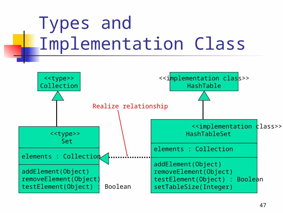
Types and Implementation Class
<<type>>Collection
<<implementation class>>HashTable
<<type>> Set
elements : Collection
addElement(Object)removeElement(Object)testElement(Object) : Boolean
<<implementation class>> HashTableSet
elements : Collection
addElement(Object)removeElement(Object)testElement(Object) : BooleansetTableSize(Integer)
Realize relationship
48
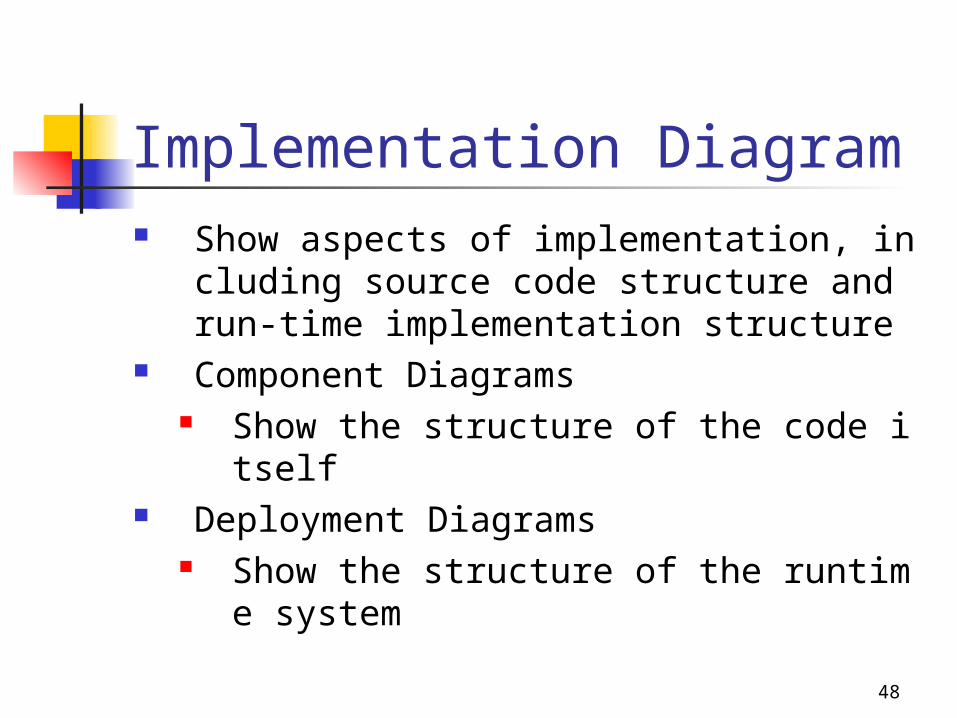
Implementation Diagram Show aspects of implementation, including sour
ce code structure and run-time implementation structure
Component Diagrams Show the structure of the code itself
Deployment Diagrams Show the structure of the runtime system
49
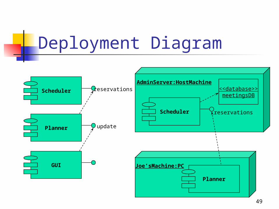
Deployment Diagram
Scheduler
Planner
GUI
reservations
update
Scheduler
Planner
<<database>>meetingsDB
AdminServer:HostMachine
Joe’sMachine:PC
reservations
50
Summary UML is a standard for OOA&D Software Development
Requirement Analysis Object-Oriented Analysis Object-Oriented Design Code Test