
UMCP Plant Sciences - BidNet
88
CHESAPEAKE, VA 757-436-1301 ● 800-394- 2373 FAX 757-436-3176 CLAYTON, NC 919-550-2699 ● 800-849-8886 FAX 919-550-0719 DOVER, DE 302-527-2373 ● 888-553-2373 FAX 302-346-4806 RICHMOND, VA 804-447-2900 FAX 804-447-2866 LAURINBURG, NC 910-276-1112 FAX 910-276-5811 York, PA 717-741-9980 ● 866-922-2373 FAX 717-741-9981 WILMINGTON, NC 910-762-5418 ● 800-948-5489 FAX 910-762-9279 UMCP Plant Sciences Fire Alarm Design University of Maryland, Plant Sciences Building 4291 Fieldhouse Dr. College Park, MD 20742 Fire Alarm System Submittal A WOMAN OWNED COMPANY 7512 CONNELLEY DRIVE ● HANOVER, MD 21076 410-768-2200 ● 800-966-2212 ● FAX 410-768-5649 ● WWW.BFPE.COM MEMBER AUTOMATIC FIRE ALARM ASSOCIATION MEMBER BUILDING OWNERS AND MANAGERS ASSOCIATION MEMBER NATIONAL ASSOCIATION OF FIRE EQUIPMENT DISTRIBUTORS MEMBER NATIONAL FIRE PROTECTION ASSOCIATION MEMBER FIRE SUPPRESSION SYSTEMS ASSOCIATION MEMBER AMERICAN FIRE SPRINKLER ASSOCIATION
Transcript of UMCP Plant Sciences - BidNet

CHESAPEAKE, VA
757-436-1301 ● 800-394-
2373
FAX 757-436-3176
CLAYTON, NC
919-550-2699 ● 800-849-8886
FAX 919-550-0719
DOVER, DE
302-527-2373 ● 888-553-2373
FAX 302-346-4806
RICHMOND, VA
804-447-2900
FAX 804-447-2866
LAURINBURG, NC
910-276-1112
FAX 910-276-5811
York, PA
717-741-9980 ● 866-922-2373
FAX 717-741-9981
WILMINGTON, NC
910-762-5418 ● 800-948-5489
FAX 910-762-9279
UMCP Plant Sciences
Fire Alarm Design
University of Maryland, Plant Sciences Building
4291 Fieldhouse Dr.
College Park, MD 20742
Fire Alarm System Submittal
A WOMAN OWNED COMPANY
7512 CONNELLEY DRIVE ● HANOVER, MD 21076
410-768-2200 ● 800-966-2212 ● FAX 410-768-5649 ● WWW.BFPE.COM
MEMBER AUTOMATIC FIRE ALARM ASSOCIATION
MEMBER BUILDING OWNERS AND MANAGERS ASSOCIATION
MEMBER NATIONAL ASSOCIATION OF FIRE EQUIPMENT DISTRIBUTORS
MEMBER NATIONAL FIRE PROTECTION ASSOCIATION
MEMBER FIRE SUPPRESSION SYSTEMS ASSOCIATION
MEMBER AMERICAN FIRE SPRINKLER ASSOCIATION

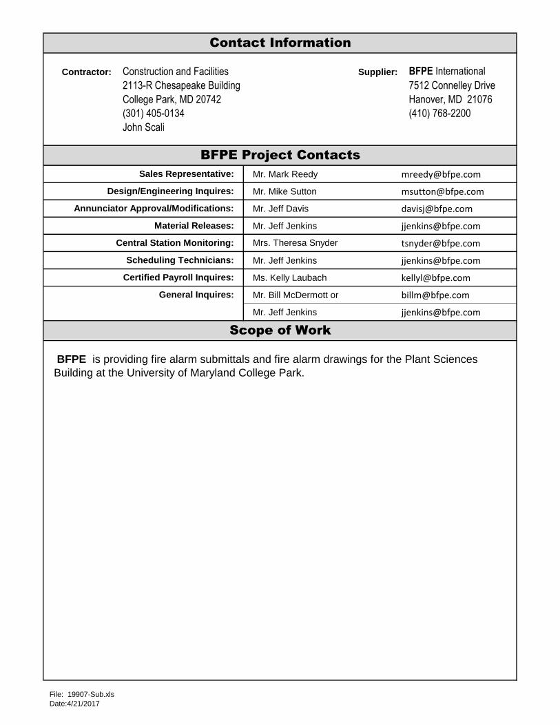
Contractor: Supplier: BFPE International
7512 Connelley Drive
Hanover, MD 21076
(410) 768-2200
Mr. Mark Reedy [email protected]
Mr. Mike Sutton [email protected]
Mr. Jeff Davis [email protected]
Mr. Jeff Jenkins [email protected]
Mr. Jeff Jenkins [email protected]
Ms. Kelly Laubach [email protected]
Mr. Bill McDermott or [email protected]
Mr. Jeff Jenkins [email protected]
Sales Representative:
Annunciator Approval/Modifications:
Material Releases:
General Inquires:
Design/Engineering Inquires:
Mrs. Theresa Snyder
BFPE is providing fire alarm submittals and fire alarm drawings for the Plant Sciences
Building at the University of Maryland College Park.
Scope of Work
Scheduling Technicians:
Central Station Monitoring:
Certified Payroll Inquires:
BFPE Project Contacts
Contact Information
Construction and Facilities
2113-R Chesapeake Building
College Park, MD 20742
(301) 405-0134
John Scali
File: 19907-Sub.xls
Date:4/21/2017

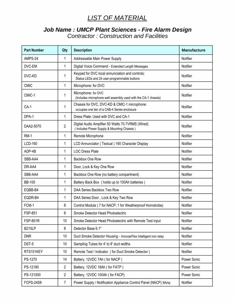
Part Number Qty Description Manufacture
AMPS-24 1 Addressable Main Power Supply Notifier
DVC-EM 1 Digital Voice Command - Extended Length Messages Notifier
DVC-KD 1Keypad for DVC local annunciation and controls:
Status LEDs and 24 user-programmable buttonsNotifier
CMIC 1 Microphone: for DVC Notifier
CMIC-1 1Microphone: for DVC
(Includes microphone well assembly used with the CA-1 chassis)Notifier
CA-1 1Chassis for DVC, DVC-KD & CMIC-1 microphone:
occupies one tier of a CAB-4 Series enclosureNotifier
DPA-1 1 Dress Plate: Used with DVC and CA-1 Notifier
DAA2-5070 2Digital Audio Amplifier 50 Watts 70.7VRMS (Wired) ( Includes Power Supply & Mounting Chassis )
Notifier
RM-1 1 Remote Microphone Notifier
LCD-160 1 LCD Annunciator ( Textual ) 160 Character Display Notifier
ADP-4B 1 LOC Dress Plate Notifier
SBB-AA4 1 Backbox One Row Notifier
DR-AA4 1 Door, Lock & Key One Row Notifier
SBB-AA4 1 Backbox One Row (no battery compartment) Notifier
BB-100 1 Battery Back Box ( holds up to 100Ah batteries ) Notifier
EQBB-B4 1 DAA Series Backbox Two Row Notifier
EQDR-B4 1 DAA Series Door , Lock & Key Two Row Notifier
FCM-1 8 Control Module ( 7 for NACP; 1 for Weatherproof Hornstrobe) Notifier
FSP-851 8 Smoke Detector Head Photoelectric Notifier
FSP-851R 10 Smoke Detector Head Photoelectric with Remote Test input Notifier
B210LP 8 Detector Base 6.1" Notifier
DNR 10 Duct Smoke Detector Housing - InnovairFlex Intelligent non relay Notifier
DST-5 10 Sampling Tubes for 4' to 8' duct widths Notifier
RTS151KEY 10 Remote Test / Indicator ( for Duct Smoke Detector ) Notifier
PS-1270 14 Battery, 12VDC 7Ah ( for NACP ) Power Sonic
PS-12180 2 Battery, 12VDC 18Ah ( for FATP ) Power Sonic
PS-121000 2 Battery, 12VDC 100Ah ( for FACP) Power Sonic
FCPS-24S8 7 Power Supply / Notification Appliance Control Panel (NACP) 8Amp Notifier
Job Name : UMCP Plant Sciences - Fire Alarm DesignContractor : Construction and Facilities
LIST OF MATERIAL


Part Number Qty Description Manufacture
ASWP-2475W-FR 1 Audible Strobe Weatherproof 30 Candela ( Wall Mount ) Red Eaton
WPBB-R 1 Weatherproof Back Box ( Red ) Use With ASWP-2475W-FR Eaton
LSTR 242Exceder LED Strobe - Multi Candela: (Wall Mount) (Red) 15, 30, 75, 110
Eaton
LSPSTR 22Exceder LED Speaker Strobe Multi Candela: (Wall Mount) (Red) 15, 30, 75, 110
Eaton
LSPSTWC 39Exceder LED Speaker Strobe Multi Candela:
(Ceiling Mount) (White) 15, 30, 75,110Eaton
LSPKWC 86 Exceder Speaker: (Ceiling Mount) (White) Eaton


Notification Appliance Circuit LoadsJob Name : UMCP Plant Sciences - Fire Alarm Design
STARTING VOLTAGE OF 20.4 VDC FACP NACP
Speaker Strobe Wall Mnt Strobe Wall Mount Speaker Str. Ceiling Mnt Voltage Drop Calc. 2 Amp 3 Amp
NAC LSPST Series LST Series LSPSTC Series Total Wiire Run Voltage Line Voltage Circuit Circuit
Area Circuit 15 30 75 110 15 30 75 110 15 30 75 95 Current Distance Drop with After Spare Spare
ID 0.030 0.040 0.115 0.200 0.030 0.040 0.115 0.200 0.065 0.105 0.189 0.249 in feet 14 AWG Drop Capacity Capacity
Ground Floor N1-1 1 5 1.115 300 1.693 18.707 62.83%
Ground Floor N1-2 2 2 4 1 2 5 1 1.714 300 2.602 17.798 42.87%
Ground Floor N1-3 1 2 2 3 1 1 0.63 NACP N1 300 0.956 19.444 79.00%
Spare N1-4 0 3.459 Total 300 0.000 20.400 100.00%
1st Floor N2-1 1 1 1 1 5 1 0.94 300 1.427 18.973 68.67%
1st Floor N2-2 8 3 1 1 0.732 300 1.111 19.289 75.60%
1st Floor N2-3 6 3 5 2 1.005 NACP N2 300 1.526 18.874 66.50%
1st Floor N2-4 2 2 3 2 1.191 3.868 Total 300 1.808 18.592 60.30%
2nd Floor N3-1 9 6 1 0.625 300 0.949 19.451 79.17%
2nd Floor N3-2 1 5 7 2 0.775 300 1.177 19.223 74.17%
2nd Floor N3-3 1 10 3 1 3 0.987 NACP N3 300 1.499 18.901 67.10%
2nd Floor N3-4 2 4 5 2 0.925 3.312 Total 300 1.404 18.996 69.17%
3rd Floor N4-1 1 7 2 1 2 0.565 300 0.858 19.542 81.17%
3rd Floor N4-2 7 1 4 3 0.905 300 1.374 19.026 69.83%
3rd Floor N4-3 3 3 3 0.555 NACP N4 300 0.843 19.557 81.50%
3rd Floor N4-4 5 2 1 2 0.475 2.5 Total 300 0.721 19.679 84.17%
4th Floor N5-1 3 5 2 2 0.65 300 0.987 19.413 78.33%
4th Floor N5-2 9 1 3 0.655 300 0.994 19.406 78.17%
4th Floor N5-3 5 1 3 2 0.665 NACP N5 300 1.010 19.390 77.83%
4th Floor N5-4 2 2 5 2 0.845 2.815 Total 300 1.283 19.117 71.83%
5th Floor N6-1 5 1 2 4 0.68 300 1.032 19.368 77.33%
5th Floor N6-2 8 3 0.585 300 0.888 19.512 80.50%
5th Floor N6-3 3 5 1 0.854 NACP N6 300 1.297 19.103 71.53%
Spare N6-4 0 2.119 Total 300 0.000 20.400 100.00%
6th Floor N7-1 5 1 2 2 0.55 300 0.835 19.565 81.67%
6th Floor N7-2 7 3 1 0.62 300 0.941 19.459 79.33%
6th Floor N7-3 7 5 1 0.974 NACP N7 300 1.479 18.921 67.53%
Spare N7-4 0 2.144 Total 300 0.000 20.400 100.00%
Totals = 4 1 7 10 122 51 64 5 36 0 3 0
Heaviest Circuit
1.714 Load
Device Count 0 =Spare Qty 0 =Spare Qty 0 =Spare Qty 0 Designation
Totals = 22 LSPSTR 242 =LSTR 39 =LSPSTWC
Total Panel
Current Load


SPKR Load on Circuits Total Speakers Speakers Speakers Speakers Speakers Speakers Speakers Circuits Total Circuits Spare
Circuit CKT Amp Wattage Tapped Tapped Tapped Tapped Tapped Tapped Tapped Wattage Wattage
Location Number Number Capacity @8 Watt @4 Watt @2 Watt @1 Watt @1/2Watt @1/4Watt @1/8 Watt Draw Capacity %
Ground Floor S1-1 1 50 30 15 70.00%
1st Floor S1-2 1 50 26 13 74.00%
2nd Floor S1-3 1 50 24 12 76.00%
3rd Floor S2-1 2 50 22 11 78.00%
4th Floor S2-2 2 50 22 11 78.00%
5th Floor S2-3 2 50 13 6.5 87.00%
6th Floor S2-4 2 50 13 6.5 87.00%
Amplifier Load on Spare
Number Amplifier Amp Capacity
Amplifier #1 40 20.00%
Amplifier #2 35 30.00%
Amplifier Load & Spare Capacity Chart
DAA2-5070
Amplifier Wattage Amplifier
Output Voltage
Speaker Load & Spare Capacity Chart
Maximum Output
50
Model Number
DAA2-5070
Amplifier
70.7
50 70.7


Qty DescriptionSupervisory
Item in Amps
Supervisory
Total in Amps
Alarm Item
in Amps
Alarm Total in
Amps
1 NFS2-3030D Fire Control Panel with Display 0.340 0.340 0.340 0.340
2 LCM-320 Loop Control Module 0.130 0.260 0.130 0.260
1 APS2-6R Auxiliary Power Supply (2) 24vdc 3 amp outputs 0.200 0.200 0.200 0.200
1 AMPS-24 Power Supply (previous version) 0.052 0.052 0.052 0.052
1 DVC-EM - Digital Voice Command - Extended Length Messages 0.440 0.440 0.440 0.440
1 DVC-KD - Keypad for DVC local annunciation and controls 0.060 0.060 0.060 0.060
1 DAA2-5070 - 50 Watt 70.7VRMS Amplifier ( Max Alarm Load ) Wire 0.400 0.400 3.750 3.750
1 RM-1 Remote Microphone 0.020 0.020 0.066 0.066
1 LCD-160 Annunciator ( Textual ) 80 Character Liquid Crystal Display 0.075 0.075 0.325 0.325
Qty Existing SLC Devices
40 NBG-12LX Manual Pull Station 0.000375 0.015000 0.000375 0.015000
69 FMM-1 Monitor Module 0.000375 0.025875 0.005100 0.351900
40 FCM-1 Control Module ( 7 New for NACPs; 1 New for ASWP WP Hornstrobe) 0.003750 0.150000 0.006500 0.260000
36 FRM-1 Relay Module 0.000255 0.009180 0.006500 0.234000
8 FSP-851 Smoke Detector Photo Electric 0.000360 0.002880 0.006500 0.052000
10 FSP-851R Smoke Detector Photo Electric with Remote Test Input 0.000360 0.003600 0.006500 0.065000
10 DNR - Duct Smoke Detector - InnovairFlex (NO Load from Housing)see Head for load 0.000000 0.000000 0.000000 0.000000
10 RTS151KEY Remote Test / Indicator ( for Duct Smoke Detector ) 0.000000 0.000000 0.012000 0.120000
Qty End SLC Devices
5 PR-1 Relay Module Multi-Voltage 24VDC, 24VAC, 120VAC 0.015 0.075 0.015 0.075
Qty NAC ( Programmable NAC, Smoke Power , Etc. )
1 ASWP-2475W-FR Weatherproof Horn Strobe -30 cd 0 0.000 0.168 0.168
Total Amps
Supervisory
Total Amps
Alarm
This battery calculation is in amps 2.529 7.234
To convert milliamp to amps multiply the milliamps X .001 ( 1 Amp = 1000 millamps ) x 24 x 0.25
To convert microamps to amps multiply the microamps X .000001 ( 1 Amp = 1000000 microamps ) for 24 hrs for 15 min
60.685 1.808
Total Amps Required for Supervisory : 60.685
Total Amps Required for Alarm : 1.808
Total Amphour Battery Required : 62.493
20% Derating Factor : 74.992
Amphour of Batteries to be supplied 100 Ah
UMCP Plant Sciences - Fire Alarm Design
Existing Fire Alarm Control Panel (FACP)
College Park, MD 20742
Battery Calculation

Qty DescriptionSupervisory
Item in Amps
Supervisory
Total in Amps
Alarm Item
in Amps
Alarm Total in
Amps
1 DAA2-5070 - 50 Watt 70.7VRMS Amplifier ( Max Alarm Load ) Wire 0.400 0.400 3.750 3.750
Total Amps
Supervisory
Total Amps
Alarm
This battery calculation is in amps 0.400 3.750
To convert milliamp to amps multiply the milliamps X .001 ( 1 Amp = 1000 millamps ) x 24 x 0.25
To convert microamps to amps multiply the microamps X .000001 ( 1 Amp = 1000000 microamps ) for 24 hrs for 15 min
9.600 0.938
Total Amps Required for Supervisory : 9.600
Total Amps Required for Alarm : 0.938
Total Amphour Battery Required : 10.538
20% Derating Factor : 12.645
Amphour of Batteries to be supplied 18 Ah
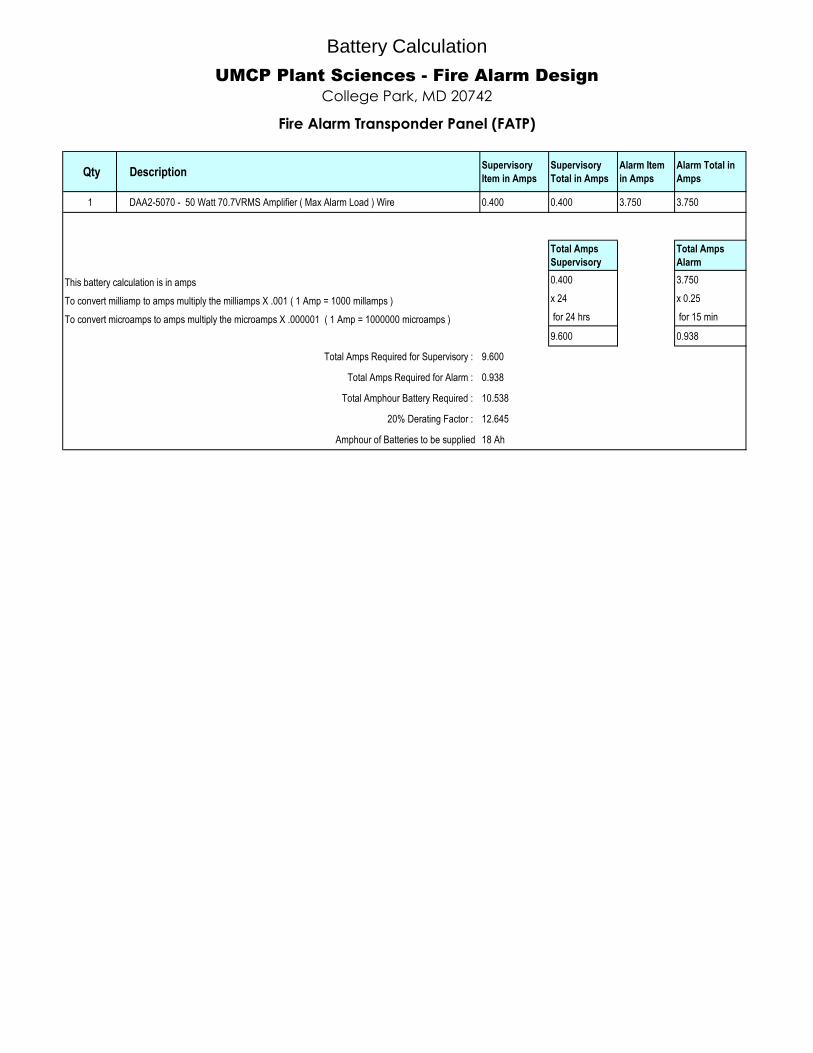
Battery Calculation
UMCP Plant Sciences - Fire Alarm Design
College Park, MD 20742
Fire Alarm Transponder Panel (FATP)


Qty DescriptionSupervisory
Item in Amps
Supervisory
Total in Amps
Alarm Item
in Amps
Alarm Total in
Amps
1 FCPS-24S8 Power Supply / Notification Appliance Control Panel (NACP) Board 0.065 0.065 0.145 0.145
1 All outputs fully loaded 8Amp 0.000 0.000 8.000 8.000
Total Amps
Supervisory
Total Amps
Alarm
0.065 8.145
x 24 x 0.25
for 24 hrs for 15 min
1.560 2.036
Total Amps Required for Supervisory : 1.560
Total Amps Required for Alarm : 2.036
Total Amphour Battery Required : 3.596
20% Derating Factor : 4.316
Amphour of Batteries to be supplied : 7 Ah
UMCP Plant Sciences - Fire Alarm Design
Power Supply / Notification Appliance Control Panel (NACP) Typical of 7
College Park, MD 20742
Battery Calculation


NFS2-3030Intelligent AddressableFire Alarm System
Intelligent Fire Alarm Control Panels
DN-7070:N • A-10
NFS2-3030 (left) and NFS2-3030 with DVC audio option (right)
7070covg.jpg
General The NFS2-3030 is an intelligent Fire Alarm Control Panel(FACP) designed for medium- to large-scale facilities. Fireemergency detection and evacuation are extremely critical tolife safety, and the NFS2-3030 is ideally suited for these appli-cations. The NFS2-3030 is part of the ONYX® Series of prod-ucts from NOTIFIER. The NFS2-3030 is ideal for virtually anyapplication because it features a modular design that is config-ured per project requirements. With one to ten Signaling LineCircuits (SLCs), the NFS2-3030 supports up to 3,180 intelli-gent addressable devices.
Information is critical to fire evacuation personnel, and theNFS2-3030’s large 640-character Liquid Crystal Display (LCD)presents vital information to operators concerning a fire situa-tion, fire progression, and evacuation details.
A host of other options are available, including single- or multi-channel voice; firefighter’s telephone; LED, LCD, or PC-basedgraphic annunciators; networking; advanced detection prod-ucts for challenging environments; wireless fire protection; andmany additional options.
Features• Certified for seismic applications when used with the appro-
priate seismic mounting kit.
• Approved for Marine applications when a marine-listed ver-sion is used with marine-listed compatible equipment. SeeDN-60688.
• Complies with UL 2572 Mass Notification Systems (NFS2-3030 version 20 or higher).
• One to ten isolated intelligent Signaling Line Circuits (SLC)Style 4, 6 or 7.
• Wireless fire protection using SWIFT Smart Wireless Inte-grated Fire Technology. See DN-60820.
• Up to 159 detectors and 159 modules per SLC; 318 devicesper loop/3,180 per FACP or network node.
– Detectors can be any mix of ion, photo, thermal, or multi-sensor; wireless detectors are available for use with theFWSG.
– Modules include addressable pull stations, normally opencontact devices, two-wire smoke detectors, notification, orrelay; wireless modules are available for use with theFWSG.
• Large 16 line, 640 character LCD backlit display or usedisplay-less as a network node.
• Network options:
– High-speed network for up to 200 nodes (NFS2-3030,NFS2-640, NFS-320(C), NFS-320SYS, NCA-2, DVC-EM,ONYXWorks, NFS-3030, NFS-640, and NCA).
– Standard network for up to 103 nodes (NFS2-3030,NFS2-640, NFS-320(C), NFS-320SYS, NCA-2, DVC-EM,ONYXWorks, NCS, NFS-3030, NFS-640, NCA, AFP-200,AFP-300/400, AFP-1010, and AM2020). Up to 54 nodeswhen DVC-EM is used in network paging.
• Built-in Alarm, Trouble, Security, and Supervisory relays.
• VeriFire® Tools online/offline program option.
• With built-in Degraded Mode operation, the system is capa-ble of general alarm if a fire alarm condition is present evenif the central processing unit (CPU) fails.
• Weekly Occupancy Schedules allow changing sensitivity bytime of day and day of week.
• EIA-485 annunciators, including custom graphics.
• History file with 4000-event capacity in nonvolatile memory,plus separate 1000-event alarm-only file.
• Advanced history filters allow sorting by event, time, date,or address.
• Alarm Verification selection per point, with automaticcounter.
• Autoprogramming and Walk Test reports.
• Multiple central station communication options:
– Standard UDACT
– Internet
– Internet/GSM
• Positive Alarm Sequence (PAS) Presignal.
• Silence Inhibit and Auto Silence timer options.
• Field-programmable on panel or on PC, with VeriFire Toolsprogram, also check, compare.
• Non-alarm points for lower priority functions.
• Remote ACK/Signal Silence/System Reset/Drill via monitormodules.
• Up to 1000 powerful Boolean logic equations.
• Supports SCS Series smoke control system in both HVACand FSCS modes.
• FM6320 approved Gas Detection System with FMM-4-20module and any FM listed gas detector.
• EIA-232 printer port.
• EIA-485 annunciator port.
DN-7070:N • 01/25/2016 — Page 1 of 8

640-CHARACTER DISPLAY FEATURES
• Backlit, 640-character display.
• Program keypad: full QWERTY keypad.
• Up to nine users, each with a password and selectableaccess levels.
• 11 LED indicators: Power; Fire Alarm; Pre-Alarm; Secu-rity; Supervisory; System Trouble; Other Event; SignalsSilenced; Point Disabled; CPU Failure; Controls Active.
• Membrane Switch Controls: Acknowledge; SignalSilence; Drill; System Reset; Lamp Test.
• LCD Display: 640 characters (16 lines x 40 characters)with long-life LED backlight.
FLASHSCAN® INTELLIGENT FEATURES
• Polls up to 318 devices on each loop in less than twoseconds.
• Activates up to 159 outputs in less than five seconds.
• Multicolor LEDs blink device address during Walk Test.
• Fully digital, high-precision protocol (U.S. Patent5,539,389).
• Manual sensitivity adjustment — up to nine levels.
• Pre-alarm ONYX intelligent sensing — up to nine levels.
• Sensitivity levels:
– Ion – 0.5 to 2.5%/foot obscuration.
– Photo – 0.5 to 2.35%/foot obscuration.
– Laser (VIEW®) – 0.02 to 2.0%/foot obscuration.
– Acclimate Plus™ – 0.5 to 4.0%/foot obscuration.
– IntelliQuad – 1.0 to 4.0%/foot obscuration.
– IntelliQuad™ PLUS – 1.0 to 4.0%/foot obscuration
• Drift compensation (U.S. Patent 5,764,142).
• Multi-detector algorithm involves nearby detectors in alarmdecision (U.S. Patent 5,627,515).
• Automatic detector sensitivity testing (NFPA-72 compliant).
• Maintenance alert (two levels).
• Self-optimizing pre-alarm.
• Programmable activation of sounder/relay bases duringalarm or pre-alarm.
• Read Status displays the level of detector cleanliness.
FSL-751 VIEW® (VERY INTELLIGENT EARLY WARNING)SMOKE DETECTION TECHNOLOGY
• Advanced ONYX intelligent sensing algorithms differentiatebetween smoke and non-smoke signals (U.S. Patent5,831,524).
• Addressable operation pinpoints the fire location.
• Early warning performance comparable to the best aspira-tion systems at a fraction of the lifetime cost.
FRM-1 Relay Contact
NOTE: CPU2-3030 firmware version 14.0 (and higher) can support LCD-160 on the RDP port, or LCD2-80 in terminal mode, but notboth at the same time.
CPU2-3030D display or
CPU2-3030ND
PRN Series Printer
NFS2-3030
Sample System Options
FAPT-851 FSL-751 FSP-851 FSA-8000
...etc.
Shown in CAB-C4 with displayDVC-EM audio in CA-1 in second tier
707
0blo
k-20
13.
wm
f
LCD-160LCD2-80
Up to 32 remote
displaysEIA-485
EIA-485
SLC Intelligent Loop
3072 annunciator/control points
Optional 2048-point UDACT
Dual phone lines to Central Station
EIA-232
DEVICES
ACM/AEM-24AT LED Annunciator
LDM-32 Custom Graphics
ACM-8R Relay Control
NBG-12LX XP6/10 I/O Modules
FMM-1IDC
FWSG
Page 2 of 8 — DN-7070:N • 01/25/2016

FAPT-851 ACCLIMATE PLUS™ LOW-PROFILE INTELLIGENT
MULTI-SENSOR
• Detector automatically adjusts sensitivity levels withoutoperator intervention or programming. Sensitivity increaseswith heat.
• Microprocessor-based technology; combination photo andthermal technology.
• Low-temperature signal at 40°F ± 5°F (4.44°C ± 2.77°C).
FSC-851 INTELLIQUAD ADVANCED MULTI-CRITERIA DETECTOR
• Detects all four major elements of a fire (smoke, heat, CO,and flame).
• Automatic drift compensation of smoke sensor and CO cell.
• High nuisance-alarm immunity.
INTELLIGENT FAAST® DETECTORS FSA-5000, FSA-8000,AND FSA-20000
• Connects directly to the SLC loop of compatible ONYXseries panels.
• Provides five event thresholds that can be individually pro-grammed with descriptive labels for control-by-event pro-gramming; uses five detector addresses.
• Uses patented particle separator and field-replaceable filterto remove contaminants.
• Advanced algorithms reject common nuisance conditions
• FSA-5000 covers 5,000 square feet through one pipe.• FSA-8000 covers 8,000 square feet through one pipe.
• FSA-20000 covers 28,800 square feet through one to fourpipes.
FCO-851 INTELLIQUAD™ PLUS
ADVANCED MULTI-CRITERIA FIRE/CO DETECTOR
• Detects all four major elements of a fire.• Separate signal for life-safety CO detection.• Optional addressable sounder base for Temp-3 (fire) or
Temp-4(CO) tone.• Automatic drift compensation of smoke sensor and CO cell.• High nuisance-alarm immunity.
FMM-4-20 GAS DETECTION MODULE
• Interface to industry-standard linear scale 4-20 mA sensors.
• Five programmable thresholds.
• FM Approved, Class 6320 (Stationary Gas Sensors/Detectors).
SWIFT WIRELESS
• Self-healing mesh wireless protocol.
• Each SWIFT Gateway supports up to 50 devices: 1 wire-less gateway and up to 49 SWIFT devices.
• Up to 4 wireless gateways can be installed with overlappingnetwork coverage.
RELEASING FEATURES
• Ten independent hazards.
• Sophisticated cross-zone (three options).
• Delay timer and Discharge timers (adjustable).
• Abort (four options).
VOICE AND TELEPHONE FEATURES
• Up to eight channels of digital audio.
• 35 watt, 50 watt, 75 watt, and 100/125 watt digital amplifiers(DAA2/DAX series and DS series).
• Solid state message generation.
• Hard-wired voice control module options.
• Firefighter telephone option.
• 30- to 120-watt analog amplifiers (AA Series).
• Backup tone generator and amplifier option.
FlashScan® Exclusive World-Leading Detector ProtocolAt the heart of the NFS2-3030 is a set of detection devices anddevice protocol — FlashScan (U.S. Patent 5,539,389). Flash-Scan is an all-digital protocol that gives superior precision andhigh noise immunity.
As well as giving quick identification of an active input device,this protocol can also activate many output devices in a frac-tion of the time required by competitive protocols. This highspeed also allows the NFS2-3030 to have the largest deviceper loop capacity in the industry — 318 points — yet everyinput and output device is sampled in less than two seconds.The microprocessor-based FlashScan® detectors have bicolorLEDs that can be coded to provide diagnostic information,such as device address during Walk Test.
ONYX Intelligent SensingONYX Intelligent Sensing is a set of software algorithms thatprovide the NFS2-3030 with industry-leading smoke detectioncapability. These complex algorithms require many calcula-tions on each reading of each detector, and are made possibleby the very high-speed microcomputer used by the NFS2-3030.
Drift Compensation and Smoothing. Drift compensationallows the detector to retain its original ability to detect actualsmoke, and resist false alarms, even as dirt accumulates. Itreduces maintenance requirements by allowing the system toautomatically perform the periodic sensitivity measurementsrequired by NFPA 72. Smoothing filters are also provided bysoftware to remove transient noise signals, usually caused byelectrical interference.
Maintenance Warnings. When the drift compensation per-formed for a detector reaches a certain level, the performanceof the detector may be compromised, and special warningsare given. There are three warning levels: (1) Low Chambervalue; (2) Maintenance Alert, indicative of dust accumulationthat is near but below the allowed limit; (3) MaintenanceUrgent, indicative of dust accumulation above the allowedlimit.
Sensitivity Adjust. Nine sensitivity levels are provided foralarm detection. These levels can be set manually, or canchange automatically between day and night. Nine levels ofpre-alarm sensitivity can also be selected, based on predeter-mined levels of alarm. Pre-alarm operation can be latching orself-restoring, and can be used to activate special control func-tions.
Self-Optimizing Pre-Alarm. Each detector may be set for“Self-Optimizing” pre-alarm. In this special mode, the detector“learns” its normal environment, measuring the peak analogreadings over a long period of time, and setting the pre-alarmlevel just above these normal peaks.
Cooperating Multi-Detector Sensing. A patented feature ofONYX Intelligent Sensing is the ability of a smoke sensor toconsider readings from nearby sensors in making alarm orpre-alarm decisions. Without statistical sacrifice in the ability toresist false alarms, it allows a sensor to increase its sensitivityto actual smoke by a factor of almost two to one.
DN-7070:N • 01/25/2016 — Page 3 of 8
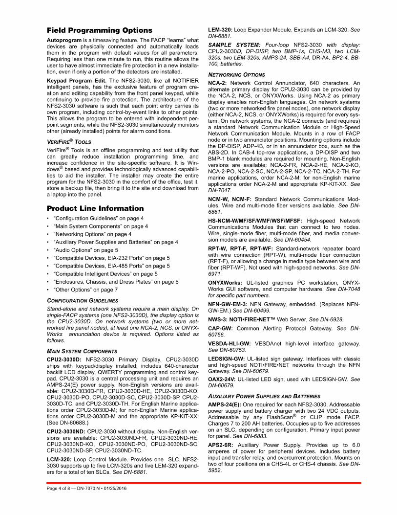
Field Programming OptionsAutoprogram is a timesaving feature. The FACP “learns” whatdevices are physically connected and automatically loadsthem in the program with default values for all parameters.Requiring less than one minute to run, this routine allows theuser to have almost immediate fire protection in a new installa-tion, even if only a portion of the detectors are installed.
Keypad Program Edit. The NFS2-3030, like all NOTIFIERintelligent panels, has the exclusive feature of program cre-ation and editing capability from the front panel keypad, whilecontinuing to provide fire protection. The architecture of theNFS2-3030 software is such that each point entry carries itsown program, including control-by-event links to other points.This allows the program to be entered with independent per-point segments, while the NFS2-3030 simultaneously monitorsother (already installed) points for alarm conditions.
VERIFIRE® TOOLS
VeriFire® Tools is an offline programming and test utility thatcan greatly reduce installation programming time, andincrease confidence in the site-specific software. It is Win-dows® based and provides technologically advanced capabili-ties to aid the installer. The installer may create the entireprogram for the NFS2-3030 in the comfort of the office, test it,store a backup file, then bring it to the site and download froma laptop into the panel.
Product Line Information• “Configuration Guidelines” on page 4
• “Main System Components” on page 4
• “Networking Options” on page 4
• “Auxiliary Power Supplies and Batteries” on page 4
• “Audio Options” on page 5
• “Compatible Devices, EIA-232 Ports” on page 5
• “Compatible Devices, EIA-485 Ports” on page 5
• “Compatible Intelligent Devices” on page 5
• “Enclosures, Chassis, and Dress Plates” on page 6
• “Other Options” on page 7
CONFIGURATION GUIDELINES
Stand-alone and network systems require a main display. Onsingle-FACP systems (one NFS2-3030D), the display option isthe CPU2-3030D. On network systems (two or more net-worked fire panel nodes), at least one NCA-2, NCS, or ONYX-Works annunciation device is required. Options listed asfollows.
MAIN SYSTEM COMPONENTS
CPU2-3030D: NFS2-3030 Primary Display. CPU2-3030Dships with keypad/display installed; includes 640-characterbacklit LCD display, QWERTY programming and control key-pad. CPU2-3030 is a central processing unit and requires anAMPS-24(E) power supply. Non-English versions are avail-able: CPU2-3030D-FR, CPU2-3030D-HE, CPU2-3030D-KO,CPU2-3030D-PO, CPU2-3030D-SC, CPU2-3030D-SP, CPU2-3030D-TC, and CPU2-3030D-TH. For English Marine applica-tions order CPU2-3030D-M; for non-English Marine applica-tions order CPU2-3030D-M and the appropriate KP-KIT-XX.(See DN-60688.)
CPU2-3030ND: CPU2-3030 without display. Non-English ver-sions are available: CPU2-3030ND-FR, CPU2-3030ND-HE,CPU2-3030ND-KO, CPU2-3030ND-PO, CPU2-3030ND-SC,CPU2-3030ND-SP, CPU2-3030ND-TC.
LCM-320: Loop Control Module. Provides one SLC. NFS2-3030 supports up to five LCM-320s and five LEM-320 expand-ers for a total of ten SLCs. See DN-6881.
LEM-320: Loop Expander Module. Expands an LCM-320. SeeDN-6881.
SAMPLE SYSTEM: Four-loop NFS2-3030 with display:CPU2-3030D, DP-DISP, two BMP-1s, CHS-M3, two LCM-320s, two LEM-320s, AMPS-24, SBB-A4, DR-A4, BP2-4, BB-100, batteries.
NETWORKING OPTIONS
NCA-2: Network Control Annunciator, 640 characters. Analternate primary display for CPU2-3030 can be provided bythe NCA-2, NCS, or ONYXWorks. Using NCA-2 as primarydisplay enables non-English languages. On network systems(two or more networked fire panel nodes), one network display(either NCA-2, NCS, or ONYXWorks) is required for every sys-tem. On network systems, the NCA-2 connects (and requires)a standard Network Communication Module or High-SpeedNetwork Communication Module. Mounts in a row of FACPnode or in two annunciator positions. Mounting options includethe DP-DISP, ADP-4B, or in an annunciator box, such as theABS-2D. In CAB-4 top-row applications, a DP-DISP and twoBMP-1 blank modules are required for mounting. Non-Englishversions are available: NCA-2-FR, NCA-2-HE, NCA-2-KO,NCA-2-PO, NCA-2-SC, NCA-2-SP, NCA-2-TC, NCA-2-TH. Formarine applications, order NCA-2-M; for non-English marineapplications order NCA-2-M and appropriate KP-KIT-XX. SeeDN-7047.
NCM-W, NCM-F: Standard Network Communications Mod-ules. Wire and multi-mode fiber versions available. See DN-6861.
HS-NCM-W/MF/SF/WMF/WSF/MFSF: High-speed NetworkCommunications Modules that can connect to two nodes.Wire, single-mode fiber, multi-mode fiber, and media conver-sion models are available. See DN-60454.
RPT-W, RPT-F, RPT-WF: Standard-network repeater boardwith wire connection (RPT-W), multi-mode fiber connection(RPT-F), or allowing a change in media type between wire andfiber (RPT-WF). Not used with high-speed networks. See DN-6971.
ONYXWorks: UL-listed graphics PC workstation, ONYX-Works GUI software, and computer hardware. See DN-7048for specific part numbers.
NFN-GW-EM-3: NFN Gateway, embedded. (Replaces NFN-GW-EM.) See DN-60499.
NWS-3: NOTI•FIRE•NET™ Web Server. See DN-6928.
CAP-GW: Common Alerting Protocol Gateway. See DN-60756.
VESDA-HLI-GW: VESDAnet high-level interface gateway.See DN-60753.
LEDSIGN-GW: UL-listed sign gateway. Interfaces with classicand high-speed NOTI•FIRE•NET networks through the NFNGateway. See DN-60679.
OAX2-24V: UL-listed LED sign, used with LEDSIGN-GW. SeeDN-60679.
AUXILIARY POWER SUPPLIES AND BATTERIES
AMPS-24(E): One required for each NFS2-3030. Addressablepower supply and battery charger with two 24 VDC outputs.Addressable by any FlashScan® or CLIP mode FACP.Charges 7 to 200 AH batteries. Occupies up to five addresseson an SLC, depending on configuration. Primary input powerfor panel. See DN-6883.
APS2-6R: Auxiliary Power Supply. Provides up to 6.0amperes of power for peripheral devices. Includes batteryinput and transfer relay, and overcurrent protection. Mounts ontwo of four positions on a CHS-4L or CHS-4 chassis. See DN-5952.
Page 4 of 8 — DN-7070:N • 01/25/2016

ACPS-610: 6.0 A or 10.0 A addressable charging power sup-ply. See DN-60244.
FCPS-24S6/-24S8: Remote 6 A and 8 A power supplies withbattery charger. See DN-6927.
BAT Series: Batteries. AMPS-24 uses two 12 volt, 7 to 200 AHbatteries. See DN-6933.
AUDIO OPTIONS NOTE: See “Enclosures, Chassis, and Dress Plates” on page 6 formounting hardware.
DVC-EM: Digital Voice Command, digital audio processor withmessage storage for up to 32 minutes of standard quality (4minutes at high quality) digital audio. See DN-7045.
DVC-RPU: Digital Voice Command Remote Paging Unit foruse with DVC-EM. Includes the keypad/display. See DN-60726.
DS-DB: Digital Series Distribution Board, provides bulk ampli-fication capabilities to the DVC-EM while retaining digital audiodistribuition capabilities. Can be configured with up to four DS-AMPs, supplying high-level risers spread throughout an instal-lation. See DN-60565.
DVC-KD: DVC-EM keypad for local annunciation and controls;status LEDs and 24 user-programmable buttons. See DN-7045.
DS-AMP/E: 125W, 25 VRMS, or 100W, 70VRMS. 70VRMSrequires DS-XF70V step-up transformer. Digital Series Ampli-fier, part of the DS-DB system. See DN-60663.
DS-RFM, DS-FM, DS-SFM: Fiber conversion modules forDVC-EM, DS-DB distribution board, and DAA2/DAX Seriesamplifiers. See DN-60633.
DAA2-5025(E): 50W, 25 Vrms Digital Audio Amplifier assem-bly with power supply; includes chassis. See DN-60556.
DAA2-5070(E): 50W, 70.7 Vrms Digital Audio Amplifierassembly with power supply; includes chassis. See DN-60556.
DAA2-7525(E): 75W, 25 Vrms digital audio amplifier assemblywith power supply; includes chassis. See DN-60556.
DAX-3525(E): 35W, 25 Vrms Digital Audio Amplifier assemblywith power supply, includes chassis. See DN-60561.
DAX-3570(E): 35W, 70.7 Vrms Digital Audio Amplifier assem-bly with power supply, includes chassis. See DN-60561.
DAX-5025(E): 50W, 25 Vrms Digital Audio Amplifier assemblywith power supply, includes chassis. See DN-60561.
DAX-5070(E): 50W, 70.7 Vrms Digital Audio Amplifier assem-bly with power supply, includes chassis. See DN-60561.
TELH-1: Firefighter’s Telephone Handset for use with theDVC-EM when mounted in the CA-2 chassis. See DN-7045.
CMIC-1: Microphone used with DVC/DVC-EM. Included withCA-2 chassis assembly. See DN-7045.
RM-1/RM-1SA: Remote microphone assemblies, mount onADP-4 (RM-1) dress panel or CAB-RM/-RMR (RM-1SA)stand-alone cabinets. See DN-6728.
AA-30: Audio Amplifier, 30 watts, 25 Vrms. Includes amplifierand audio input supervision, backup input, and automatic swi-tchover, power supply, cables. See DN-3224.
AA-120/AA-100: Audio Amplifier. AA-120 is 120 watts, 25Vrms. AA-100 is 100 watts, 70.7 Vrms. The amplifier containsan integral chassis for mounting to a CAB-B4, -C4, or -D4backbox (consumes one row). Includes audio input and ampli-fied output supervision, backup input, and automatic switcho-ver to backup tone. See DN-3224.
DAA Series Digital Audio Amplifiers: Legacy DAA Seriesamplifiers are compatible with DVC systems running SR4.0.For specific information on DAA-50 series amplifiers, refer toDN-7046. For information on DAA-7525 Series, refer to DN-60257.
COMPATIBLE DEVICES, EIA-232 PORTS
PRN-6: 80-column printer. See DN-6956.
PRN-7: 80-column printer. See DN-60897
VS4095/5: Printer, 40-column, 24 V. Order from Keltron, Inc.See DN-3260.
DPI-232: Direct Panel Interface, specialized modem forextending serial data links to remotely located FACPs and/orperipherals. See DN-6870.
COMPATIBLE DEVICES, EIA-485 PORTS
ACM-24AT: ONYX® Series ACS annunciator – up to 96 pointsof annunciation with Alarm or Active LED, Trouble LED, andswitch per circuit. Active/Alarm LEDs can be programmed (bypowered-up switch selection) by point to be red, green, or yel-low; the Trouble LED is always yellow. See DN-6862.
AEM-24AT: Same LED and switch capabilities as ACM-24AT;expands the ACM-24AT to 48, 72, or 96 points. See DN-6862.
ACM-48A: ONYX® Series ACS annunciator – up to 96 pointsof annunciation with Alarm or Active LED per circuit. Active/Alarm LEDs can be programmed (by powered-up switchselection) in groups of 24 to be red, green, or yellow. Expand-able to 96 points with one AEM-48A. See DN-6862.
AEM-48A: Same LED capabilities as ACM-48A; expands theACM-48A to 96 points. See DN-6862.
ACM-8R: Remote Relay Module with eight Form-C contacts.Can be located up to 6,000 ft. (1828.8 m) from panel on fourwires. See DN-3558.
LCD-160: Liquid Crystal Display annunciator, 160-characterbacklit. Can store character sets for multiple languages. Sup-ports Canadian requirements. See DN-6940.
LCD2-80: Terminal and ACS mode. 80-character, backlit LCDdisplay. Mounts up to 6,000 ft. (1828.8 m) from panel. Up to 32per FACP. See LCD2-80 (DN-60548).
SCS Series: Smoke control station; eight (expandable to 16)circuits. See DN-4818.
TM-4: Transmitter Module. Includes three reverse-polarity cir-cuits and one municipal box circuit. Mounts in panel moduleposition (as in single-address mode applications) or in CHS-M3 position. See DN-6860.
UDACT-2: Universal Digital Alarm Communicator Transmitter,636 channel. See DN-60686.
UZC-256: Programmable Universal Zone Coder provides pos-itive non-interfering successive zone coding. Microprocessor-controlled, field-programmable from IBM®-compatible PCs(requires optional programming kit). Mounts on a CHS-4series chassis within NFS2-3030.
COMPATIBLE INTELLIGENT DEVICES
FWSG Wireless SWIFT Gateway: Addressable gateway sup-ports wireless SLC devices. Not appropriate for ULC applica-tions. See DN-60820.
FSA-5000: Intelligent FAAST® XS Fire Alarm Aspiration Sens-ing Technology. Intelligent aspirating smoke detector for appli-cations up to 5,000 sq.ft. For Canadian applications, orderFSA-5000A.
FSA-8000: Intelligent FAAST® XM Fire Alarm AspirationSensing Technology. Intelligent aspirating smoke detector forapplications up to 8,000 sq.ft. For Canadian applications,order FSA-8000A. See DN-60792.
DN-7070:N • 01/25/2016 — Page 5 of 8

FSA-20000: Intelligent FAAST® XT Fire Alarm AspirationSensing Technology. Intelligent aspirating smoke detector forapplications up to 28,800 sq.ft. For Canadian applications,order FSA-20000A. See DN-60849.
FSB-200: Intelligent beam smoke detector. See DN-6985.
FSB-200S: Intelligent beam smoke detector with integral sen-sitivity test. See DN-6985.
FSC-851: FlashScan IntelliQuad Advanced Multi-CriteriaDetector. See DN-60412.
FCO-851: FlashScan IntelliQuad PLUS Advanced Multi-Crite-ria Fire/CO Detector. See DN-60689.
FSI-851: Low-profile FlashScan ionization detector. See DN-6985.
FSP-851: Low-profile FlashScan photoelectric detector. SeeDN-6935.
FSP-851R: Low-profile intelligent photoelectric sensor, remotetest capable. For use with DNR(W). See DN-6935.
FSP-851T: Low-profile FlashScan photoelectric detector with135°F (57°C) thermal. See DN-6935.
FST-851: FlashScan thermal detector 135°F (57°C). See DN-6936.
FST-851R: FlashScan thermal detector 135°F (57°C) withrate-of-rise. See DN-6936.
FST-851H: FlashScan 190°F (88°C) high-temperature thermaldetector. See DN-6936.
FAPT-851: FlashScan Acclimate Plus™ low-profile multi-sen-sor detector. See DN-6937.
FSL-751: FlashScan VIEW® laser photo detector. See DN-6886.
DNR: InnovairFlex low-flow non-relay duct-detector housing(order FSP-851 separately). Replaces FSD-751PL/FSD-751RPL. See DN-60429.
DNRW: Same as above with NEMA-4 rating, watertight. SeeDN-60429.
B224RB: Low-profile relay base. See DN-60054.
B224BI: Isolator base for low-profile detectors. See DN-60054.
B210LP: Low-profile base. Standard U.S. style. ReplacesB710LP. See DN-60054.
B501: European-style, 4" (10.16 cm) base. See DN-60054.
B200S: Intelligent programmable sounder base, capable ofproducing a variety of tone patterns including ANSI Temporal3. Compatible with sychronization protocol. See DN-60054.
B200S-LF: Low-frequency version of B200S. See DN-60054.
B200SCOA: Based on B200SA, with added CO detectormarkings in English/French. For Canadian applications only.
B200SR: Sounder base, Temporal 3 or Continuous tone. SeeDN-60054.
B200SR-LF: Low-frequency version of B200SR. See DN-60054.
FMM-1: FlashScan monitor module. See DN-6720.
FDM-1: FlashScan dual monitor module. See DN-6720.
FZM-1: FlashScan two-wire detector monitor module. SeeDN-6720.
FMM-101: FlashScan miniature monitor module. See DN-6720.
FMM-4-20: FlashScan 4-20 mA protocol monitor module. SeeDN-60411.
FCM-1: FlashScan control module. See DN-6724.
FCM-1-REL: FlashScan releasing control module. See DN-60390.
FTM-1: Firephone Telephone Module connects a remote fire-fighter telephone to a centralized telephone console. Reportsstatus to panel. Wiring to jacks and handsets is supervised.See DN-6989.
FRM-1: FlashScan relay module. See DN-6724.
FDRM-1: FlashScan dual monitor/dual relay module. See DN-60709.
NBG-12LX: Manual pull station, addressable. See DN-6726.
ISO-X: Isolator module. See DN-2243.
ISO-6: Six Fault isolator module. For Canadian applicationsorder ISO-6A. See DN-60844.
XP6-C: FlashScan six-circuit supervised control module. SeeDN-6924.
XP6-MA: FlashScan six-zone interface module; connectsintelligent alarm system to two-wire conventional detectionzone. See DN-6925.
XP6-R: FlashScan six-relay (Form-C) control module. SeeDN-6926.
XP10-M: FlashScan ten-input monitor module. See DN-6923.
SLC-IM: SLC integration module, for VESDAnet detectors.See DN-60755.
ENCLOSURES, CHASSIS, AND DRESS PLATES
CAB-4 Series Enclosure: NFS2-3030 mounts in a standardCAB-4 Series enclosure (available in four sizes, “A” through“D”). Backbox and door ordered separately; requires BP2-4battery plate. A trim ring option is available for semi-flushmounting. See DN-6857.
EQ Series Cabinets: EQ series cabinets will house amplifiers,power supplies, battery chargers and control modules. EQcabinets are available in three sizes, “B” through “D”. See DN-60229.
CAB-BM Marine System: Protects equipment in shipboardand waterfront applications. Order CPU2-3030D-M; for non-English marine applications order CPU2-3030D and appropri-ate KP-KIT-XX. Also order BB-MB for systems using 100 AHbatteries. For a full list of required and optional equipment, seeDN-60688.
CHS-M3: Mounting chassis for CPU2-3030. One required foreach CPU2-3030D/3030ND.
CA-2: Chassis for FACP control panel when DVC-EM is usedwith firefighter's telephone. Mounts in the top two rows of aCAB-4 series enclosure.
DP-DISP: Dress panel for top row in cabinet with CPU2-3030D installed.
DP-1B: Blank dress panel. Provides dead-front panel forunused tiers; covers DAA2/DAX series or AA-series amplifier.See DN-7046.
CHS-BH1: Battery chassis; holds two 12.0 AH batteries.Mounts on the left side of DAA2 chassis. See DN-7046.
CA-1: Chassis, occupies one tier of a CAB-4 Series enclo-sure. The left side accommodates one DVC-EM and a DVC-KD (optional); and the right side houses a CMIC-1 microphoneand its well (optional). See DN-7045.
CA-2: Chassis assembly, occupies two tiers of a CAB-4 Seriesenclosure. The left side accommodates one DVC-EM mountedon a half-chassis and one NFS2-3030 or NCA-2 mounted on ahalf-chassis. The right side houses a microphone/handsetwell. The CA-2 assembly includes CMIC-1 microphone. ADDRSeries doors with two-tier visibility are available for use with
Page 6 of 8 — DN-7070:N • 01/25/2016

the CA-2 configuration: ADDR-B4, ADDR-C4, ADDR-D4(below).
ADDR-B4: Two-tier-sized door designed for use with the CA-2chassis configuration. ADDR Series doors are similar to CAB-4 Series “DR” doors, but a clear window space exposes thetop two tiers of the CAB-4 enclosure. Use an SBB-B4 backboxwith the ADDR-B4. See DN-7045, DN-6857.
ADDR-C4: Three-tier-sized door designed for use with theCA-2 chassis configuration. ADDR Series doors are similar toCAB-4 Series “DR” doors, but a clear window space exposesthe top two tiers of the CAB-4 enclosure. Use an SBB-C4backbox with the ADDR-C4. See DN-7045, DN-6857.
ADDR-D4: Four-tier-sized door designed for use with the CA-2 chassis configuration. ADDR Series doors are similar toCAB-4 Series “DR” doors, but a clear window space exposesthe top two tiers of the CAB-4 enclosure. Use an SBB-D4backbox with the ADDR-D4. See DN-7045, DN-6857.
DPA-1: Dress panel, used with the CA-1 chassis when config-ured with a DVC-EM, DVC-KD, and CMIC-1. See DN-7045.
DPA-2: Dress Panel used with the CA-2 chassis assembly.
DPA-1A4: Dress panel, used with the CA-1 chassis when theCMIC-1 is not used. Provides mounting options on right twobays for two ACS annunciators, or for blank plates. See DN-7045.
ADP-4B: Annunciator dress plate. Mounts in rows 2, 3 or 4 ofa CAB-4 series enclosure. Used with ACS series annuncia-tors.
BMP-1: Blank module for unused module positions.
DP-1B: Blank dress panel. Provides dead-front panel forunused tiers; covers DAA2/DAX series or AA-series amplifier.
BP2-4: Battery plate, required.
CHS-4L: Low-profile four-position Chassis. Mounts two AA-30amplifiers.
CHS-4N: Chassis for mounting up to four APS-6Rs.
CHS-6: Chassis used with the XP6 and XP10 Multi-Modules.Mounts up to six modules in any CAB-4 series row.
BB-100: Backbox for batteries and power supplies. The BB-100 is used to mount up to two 100 AH batteries and powersupply, if needed. 30" (76.20 cm) wide x 25" (63.50 cm) high x7.5" (19.05 cm) deep; depth includes door.
BB-200: Backbox for batteries and power supplies. Holds upto four 100 AH batteries (200 AH capacity) and power supply.30" (76.20 cm) wide x 36" (91.44 cm) high x 7.5" (19.05 cm)deep; depth includes door.
NFS-LBB: Battery Box. The NFS-LBB is used to mount up totwo 55 AH batteries. Dimensions: Box: 24" (610 mm) wide x14" (356 mm) high x 7.75" (197 mm) deep. Door: 24.125" (613mm) wide x 14.25" (362 mm) high; door adds 0.0625" (approx.1.6 mm) to depth.
BB-UZC: Backbox for housing the UZC-256 for applicationswhere the UZC will not fit in panel enclosure. Black; for red,order BB-UZC-R. See DN-3404.
SEISKIT-CAB: Seismic mounting kit. Required for seismic-certified applications with NFS2-3030 and other equipmentmounted in CAB-4 Series Enclosures. Includes battery bracketfor two 26 AH batteries.
SEISKIT-LBB: Seismic kit for the NFS-LBB. Includes batterybracket for two 55 AH batteries.
OTHER OPTIONS
411: Slave digital alarm communicator. See DN-6619.
411UDAC: Digital alarm communicator. See DN-6746.
IPDACT-2, IPDACT Internet Monitoring Module: Connectsto primary and secondary DACT telephone output ports forinternet communications over customer-provided Ethernetconnection. Requires compatible Teldat VisorALARM CentralStation Receiver. Can use DHCP or static IP. See DN-60408.
IPCHSKIT: IP Communicator Chassis Mounting Kit. Formounting an IPDACT-2/2UD onto the panel chassis or CHS-4series chassis. Use IPENC for external mounting applications.
IPSPLT: Y-adapter option allow connection of both panel dialeroutputs to one IPDACT-2/2UD cable input.
IPENC: External enclosure for IPDACT, includes IPBRKTmounting bracket; Red; for black, order IPENC-B.
IPGSM-4G: Internet and Digital Cellular Fire Alarm Communica-tor. Provides selectable configurable paths: cellular only, IP only,or IP primary with cellular backup. Connects to the primary andsecondary ports of a DACT. For Canadian applications orderIPGSM-4GC. See DH-60769.
NOTE: For other options including compatibility with retrofit equip-ment, refer to the panel's installation manual, the SLC manual, andthe Device Compatibility Document.
System Specifications
SYSTEM CAPACITY
• Intelligent Signaling Line Circuits ...........1 expandable to 10
• Intelligent detectors .......................................... 159 per loop
• Addressable monitor/control modules .............. 159 per loop
• Programmable software zones............................. over 2000
• ACS annunciators per CPU2-3030 .......................32 address x 64 or 96 points
NOTE: The CPU2-3030 can support up to 96 annunciatoraddress points per ACM-24AT/-48A.
SPECIFICATIONS
Primary Input Power:
– AMPS-24: 110-120 VAC, 50/60 Hz, 4.5 A maximum.
– AMPS-24E: 240 VAC, 50/60 Hz, 2.25 A maximum.
DC Output:
– Main 24 VDC: Up to 5.0 A
– Aux 24 VDC: Up to 5.0 A
– 5 VDC: Up to 0.15 A.
Current draw (Standby/Alarm):
– CPU2-3030D board: 0.340 A.
– CPU2-3030ND board: 0.120 A.
– LCM-320: 0.130 A.
– LEM-320: 0.100 A.
– AMPS-24(E)*: 0.13 A. (Draws power from secondary power source only.)
NOTE: See AMPS-24(E) Manual 51907 for a complete currentdraw calculation sheet and details of input and output values.
Battery charger range: 7 AH – 200 AH. Use separate cabinetfor batteries over 26 AH.
Float Rate: 27.6 V.
SHIPPING WEIGHT
• CPU2-3030D: 5.95 lb (2.70 kg).
• CPU2-3030ND: 2.90 lb (1.32 kg).
TEMPERATURE AND HUMIDITY RANGES
This system meets NFPA requirements for operation at 0 –49°C/32 – 120°F and at a relative humidity 93% ± 2% RH(noncondensing) at 32°C ± 2°C (90°F ± 3°F). However, theuseful life of the system's standby batteries and the electronic
DN-7070:N • 01/25/2016 — Page 7 of 8

IntelliQuad™, NOTI•FIRE•NET™, ONYXWorks™, and SWIFT™ are alltrademarks; and Acclimate® Plus™, FlashScan®, Intelligent FAAST®,NOTIFIER®, ONYX®, VeriFire® Tools, and VIEW® are all registeredtrademarks of Honeywell International Inc. ©2016 by Honeywell International Inc. All rights reserved. Unauthorized useof this document is strictly prohibited.
components may be adversely affected by extreme tempera-ture ranges and humidity. Therefore, it is recommended thatthis system and its peripherals be installed in an environmentwith a normal room temperature of 15 – 27°C/60 – 80°F.
AGENCY LISTINGS AND APPROVALS
These listings and approvals apply to the modules specified inthis document. In some cases, certain modules or applicationsmay not be listed by certain approval agencies, or listing maybe in process. Consult factory for latest listing status.
• UL Listed: S635.
• ULC Listed: S635.
• MEA: 232-06-E.
• Fire Dept. of New York: COA#6114.
• CSFM: 7165-0028:0224 (Commercial).
• FM Approved.
• FM6320 Approved. Class 6320 for Gas Detection.
• City of Chicago.
• City of Denver.
• Singapore Productivity and Standards Board (PSB).
• CCCF listed.
• Fire Services Department (Hong Kong).
Marine Applications: Marine approved systems must be con-figured using components itemized in this document. (SeeMain System Components, in “Product Line Information.) Spe-cific connections and requirements for those components aredescribed in the installation document, PN 54756. When theserequirements are followed, systems are approved by the fol-lowing agencies:
• US Coast Guard 161.002/55/0 (Standard 46 CFR and161.002).
• Lloyd's Register 11/600013 (ENV 3 category).• American Bureau of Shipping (ABS) Type Approval. NOTE: For information on marine applications, see DN-60688.
STANDARDS
The NFS2-3030 complies with the following UL Standards andNFPA 72, International Building Code (IBC), and CaliforniaBuilding Code (CBC) Fire Alarm Systems requirements:
• UL 864 (Fire).
• UL 1076 (Burglary).
• UL 2572 (Mass Notification Systems). (NFS2-3030 version20 or higher)
• LOCAL (Automatic, Manual, Waterflow and SprinklerSupervisory).
• AUXILIARY (Automatic, Manual and Waterflow) (requiresTM-4).
• REMOTE STATION (Automatic, Manual, Waterflow andSprinkler Supervisory) (requires TM-4).
• PROPRIETARY (Automatic, Manual, Waterflow and Sprin-kler Supervisory). Not applicable for FM.
• EMERGENCY VOICE/ALARM.
• OT, PSDN (Other Technologies, Packet-switched Data Net-work).
• IBC 2012, IBC 2009, IBC 2006, IBC 2003, IBC 2000 (Seis-mic).
• CBC 2007 (Seismic).
Page 8 of 8 — DN-7070:N • 01/25/2016
This document is not intended to be used for installation purposes. We try to keep our product information up-to-date and accurate.
We cannot cover all specific applications or anticipate all requirements. All specifications are subject to change without notice.
For more information, contact Notifier. Phone: (203) 484-7161, FAX: (203) 484-7118.www.notifier.com
Made in the U.S. A.

DN-6883:B • 10/15/09 — Page 1 of 2
AMPS-24/EPower Supplyfor the NFS-3030, NFS2-3030 and NCA-2
CatalogSection
DN-6883:B
GeneralNOTIFIER’s AMPS-24/E is an addressable power supply andbattery charger with up to three 24 VDC outputs. It operates ineither FlashScan® or CLIP (Classic Loop Interface Protocol)mode with the NFS-3030/NFS2-3030 Fire Alarm Control Panel(FACP). It can also be used as the primary power supply forthe NCA-2 Network Control Annunciator.
Features• Addressable by NFS-3030/NFS2-3030 FACP.• Selectable charging current charges 7 AH to 200 AH batter-
ies.• Isolated Signaling Line Circuit (SLC) interface.
• Trouble bus input for use with normally-open dry contacts oropen-collector circuit.
• USB Type B connector for programming installation param-eters.
• Brownout detection.• Battery/battery charger supervision.• Secondary Power Auxiliary Outputs: 24V @ 0.5A and 5V @
0.15A.• AC loss detection and AC loss delay reporting.
• Mounts in a CAB-4 Series enclosure, EQ Cabinet Seriesenclosure, BB-25, BB-100, or BB-200 Battery Backbox.
Specifications• Primary (AC) power:
AMPS24: 110-120 VAC 50/60 Hz input, 5 A maximum;AMPS24E: 220-240 VAC 50/60 Hz input, 2.5 A maximum.
• MAIN 24V Output - filtered power-limited power. Refer totable for configuration/current information.
• AUX 24V - provides filtered power-limited power for addi-tional components. Refer to table above for configuration/current information.
• Secondary power (battery) charging circuit: Current-limited,sealed lead-acid battery charger which will charge 7 to 200AH batteries. Selectable charging current: 1.0 A, 2.0 A or 5.0 A.
• Secondary power auxiliary outputs.• Wire sizes: 10 AWG (5.26 mm²) to 22 AWG (0.326 mm²).• Battery fuse (F2): 15 A, fast-acting.
• Shipping Weight: 4.25 lb
Agency Listings and ApprovalsThese listings and approvals apply to the AMPS-24/E powersupply. In some cases, certain modules may not be listed bycertain approval agencies, or listing may be in process. Con-sult factory for latest listing status.
• UL: S635• ULC: CS118
• City of Chicago • City of Denver• MEA: 345-02-E
• CSFM: 7165-0028:224 • FM: Approved• FDNY: #6026
Product Line InformationAMPS-24: Addressable power supply/battery charger
AMPS-24E: Same as AMPS-24: 220-240VAC operation
Charger Setting/Battery Size
Main 24V (TB 1 on Main Control Unit)
Max. Current
*Total AUX 24V (TB3 on Main Control Unit with TB2 on CPS-
24) Max. Current
1A/7-26AH Bat-teries 5A 3A
2A/12-60AH Bat-teries 5A 3A
5A/55-200AHConfiguration 1Configuration 2
5A3A
0A1A
Disabled 5A 5A
* Maximum current for all AUX 24 volt outputs. Note that TB2 on CPS-24 is limited to 0.5A.

Page 2 of 2 — DN-6883:B • 10/15/09
FlashScan® is a registered trademark of Honeywell International Inc. ©2009 by Honeywell International Inc. All rights reserved. Unauthorized useof this document is strictly prohibited.
This document is not intended to be used for installation purposes. We try to keep our product information up-to-date and accurate.
We cannot cover all specific applications or anticipate all requirements. All specifications are subject to change without notice.
For more information, contact Notifier. Phone: (203) 484-7161, FAX: (203) 484-7118.www.notifier.com
Made in the U.S. A.

DAA2 SeriesDigital Audio Amplifiers
Voice Control Systems
DN-60556:B
GeneralThe DAA2 Series amplifiers are multi-featured amplifiers withdigital audio functionality. Each DAA2 is capable of accessingand processing one of up to eight audio channels on the DVCaudio loop, amplifying the signal, and distributing it via fourClass B or two Class A outputs. A DAA2-50 or DAA2-75series amplifier is capable of mounting an optional BDA Digi-tal amplifier, which can be used to provide one-to-one ampli-fier backup, or to support two-channel operation, orincreased output wattage to 100W (100W option applies toDAA2-50 series only, other rules apply).
The DAA2 has two wire digital audio ports to connect to wireDAL (digital audio loop) segments. Either or both ports maybe converted to fiber using fiber option modules.
Up to 32 devices, such as DAA2 amplifiers, can be con-nected to the DAL on one DVC Digital Voice Command unit.DAA2 amplifiers may be mixed with DAX and DAA seriesamplifiers on the same DAL.
An optional Firefighter telephone riser on the DAA2 supportslocal and network FFT communications. A DAA2 also sup-ports use of an RM-1 remote microphone.
DAA2 amplifiers can store backup alarm and trouble mes-sages, and provide an adjustable background music input.
Features• Listed to UL Standard 864, 9th edition.
• 50 W total output power at 25 VRMS (all DAA2-5025 mod-els) or 70 VRMS (all DAA2-5070 models).
• 75 W total output power at 25 VRMS (all DAA2-7525 mod-els).
• Supports two Class A high-level audio outputs; or fourClass B outputs.
• Optional BDA amplifiers support alternative configura-tions.
• Backup amplifier - supports one-to-one backup (allDAA2 models).
• Primary amplifier - supports two-channel operation (allDAA2 models).
• Primary amplifier - increase power up to 100W, one- ortwo-channel operation. (DAA2-50 series only, configura-tion rules apply.)
• Supports one-to-many amplifier backup applications usingthe same model DAA2.
• Firefighter telephone riser supports 7 active firefightertelephones. System Release 3.0 and higher supportsoptional configurations: direct connection for up to 7 fire-fighter telephones, or connection to multiple FTM-1 mod-ules.
• Remote microphone paging option with RM-1.
• Audio output activation via network control-by-event equa-tions resident within the DVC.
• Two wire digital audio ports that can be converted to fiberusing fiber option modules. Support Style 4 or 7 configura-tions.
• Auxiliary input for 1 VRMS, to be used for backgroundmusic input, an interface with a telephone paging source,or other compatible audio sources. Audio levels can beadjusted by end user. Optional supervision through pro-gramming.
• Isolated alarm bus input, to be used for backup activationof alarm messages when normal digital communication islost.
• Programmable through VeriFire® Tools.
• Up to 106 seconds of backup digital message storage foruse in the event of communication loss (from the Veri-Fire® Tools message library, or created by the installer).
• Battery charger disable provides battery sharing option forup to four DAA2s.
• Disconnect of deeply-discharged battery (low battery dis-connect).
InstallationThe DAA2 arrives from the factory already installed on itschassis. The DAA2 mounts in one row of any EQ or CAB-4Series cabinet: The CAB-4 row can be covered using a DP-1B dress panel, ordered separately.
One or two fiber option modules will plug directly onto aDAA2 for simple installation. A BDA backup amplifier mountsdirectly onto a DAA2.
Batteries for the DAA2 may be installed in any of the followingconfigurations:
• In a CHS-BH1 optional battery chassis. The CHS-BH1battery chassis will hold two 12.0 AH batteries, andmounts on the left side of the DAA2 chassis, so that theDAA2 and batteries are contained in a single cabinet tier.
• In the battery row (bottom) of the CAB-4 Series cabinet, orin the bottom row of an EQ Series cabinet.
• In a cabinet adjacent to the cabinet that holds the DAA2,with connections in conduit. External battery charging issupported.
DN-60556:B • 11/17/2014 — Page 1 of 4

Specifications
CPS-24 POWER SUPPLY BOARD
AC power (TB1)
• Models using 120 VAC, 60 Hz input:
– DAA2-5025 - 4.68A max.
– DAA2-5070 - 4.69A max.
– DAA2-7525 - 4.68A max.
• “E” version models using 220-240 VAC 60 Hz input:
– DAA2-5025E - 2.68A max.
– DAA2-5070E - 2.68A max.
– DAA2-7525E - 2.68A max.
Recommended wiring: 12 to 14 AWG (1.6 mm O.D.) with600 VAC insulation.
Shipping Weight: 13 lb (5.9 kg).
Secondary Power 5V and 24V AUX Outputs (TB2):24 V AUX: Power-limited, 24V @ 0.5A, utilizes wire sizes 12-18 AWG (3.31 mm2 - 2.08 mm2.5 V: Future Use.
Battery Connections: Supplied cable connections to batter-ies.
Battery Charger: Current-limited sealed lead acid batterycharger which charges two 12 volt batteries in series, up to200 AH.
Table 1: Battery Charging Capabilities
DAA2 BOARDS
Digital Audio Ports, wire media, A and B (TB2, TB3): Max-imum distance per segment is 1900 feet (579.12 m) onBelden 5320UJ (18AWG, TP) FPL cable: 18 AWG (0.821mm2) twisted-pair, unshielded, power-limited. For approvedcable types, see wiring documentation, P/N 52916ADD: CApproved Wire Cables for Digital Audio Loops.
Digital Audio Ports, fiber media, fiber option modules:Digital audio loop connectors support single- and multi-modefiber with the use of fiber option modules. Refer to the FiberOption Module datasheet for fiber specifications.
Alarm Bus: Power-limited, supervised by source. Recom-mended wiring: 14-18 AWG twisted-pair. Requires 16VDCminimum @ 20mA across the terminals to activate. Nominal24VDC.
Remote Microphone Interface: RMI power: +24VDC,power-limited @ 100mA. Supervised. Recommended wiring:14-18 AWG twisted-pair, Max. 14 AWG. Nominal AC signalstrength 2.5VRMS, 3VRMS Max. Maximum distance betweenremote microphone and DAA2: 100 ft (304.8 m).
FFT Riser: Power-limited output, supervised. Class A orClass B operation. Class B 2-wire connections require a 3.9k
ohm 1/2 watt resistor (P/N R-3.9K). Max. wiring resistance(including individual telephone zone to last handset) permit-ted is 50 ohms, 10,000 ft (3048 m) max. wiring distance at 14AWG to last handset.
Auxiliary Input: Signal strength from low-level analog audioinput (such as background music or telephone paging): 1Vp-pmax. Optional supervision through programming. Recom-mended wiring: 14-18 AWG, twisted-pair. Auxiliary inputsource must be within 25 ft. (7.6 m) of the DAA2, and withinthe same room.
Speaker circuits: Power-limited outputs (exception: a DAA2-5070 speaker circuit used with any Canadian Room Isolatormodule is non-power limited. Speaker circuit 1 (TB10) cannot be used.). Supervision determined by programming.DAA2-5025/70, Each circuit rated up to 50 watts*. DAA2-7525, each circuit rated up to 75 watts*. Recommended wir-ing: 12-18 AWG twisted-pair (shielded recommended). ClassB or Class A: Class B requires 20k end-of-line resistors(included, P/N ELR-20K). Class A requires 10k end-of-lineresistors (included, P/N R-10K) on the return. *total wattage may vary per configuration.
Backup: High-level audio input: 25VRMS (DAA2-5025 andDAA2-7525). 70 VRMS (DAA2-5070). Recommended wiring:14-18 AWG. Not supervised when inactive. Supervised bybackup source when active. Must be in same room or enclo-sure.
Standards and CodesThe DAA2 Series Digital Audio Amplifiers comply with the fol-lowing standards:
• NFPA 72 2007 National Fire Alarm Code
• Underwriter Laboratories Standard UL 864
• Underwriter Laboratories of Canada (ULC) ULC-S527-99Standard of Control Units for Fire Alarm Systems.
• Part 15 Class A conducted and radiated emissions asrequired by the FCC.
• IBC 2012, IBC 2009, IBC 2006, IBC 2003, IBC 2000(Seismic).
• CBC 2007 (Seismic)
Listings and ApprovalsThese listings and approvals apply to the basic DAA2 SeriesDigital Audio Amplifiers. In some cases, certain modules maynot be listed by certain agencies, or listing may be in process.Consult factory for latest listing status.
• UL Listed: S635.
• ULC LIsted: S635.
• CSFM: 7165-0028:0234 (NFS2-640/NFS-320), 7165-0028:0224 (NFS2-3030).
• Fire Dept. of New York: COA#6121 (NFS2-640/NFS-320),COA#6114 (NFS2-3030).
Product Line Information
50 WATT DAA2 AMPLIFIERS
Shipped mounted to the chassis.
DAA2-5025: 120 VAC Digital Audio Amplifier (50 W, 25VRMS).
DAA2-5070: 120 VAC Digital Audio Amplifier (50 W, 70VRMS).
Charge 7 AH to 26 AH
Batteries
Charge 26 AH to < 50 AH
Batteries
Charge 50 AH to 200 AH
Batteries
DAA2-5025DAA2-5070
Yes Yes Yes
DAA2-7525 Yes Yes No
DAA2-5025 or DAA-5070 w/BDA in Group 2 of VeriFire® Tools
No No No
Page 2 of 4 — DN-60556:B • 11/17/2014

DAA2-5025E: 220-240 VAC Digital Audio Amplifier (50 W,25 VRMS).
DAA2-5070E: 220-240 VAC Digital Audio Amplifier (50 W,70 VRMS).
75 WATT DAA2 AMPLIFIERS
Shipped mounted to the chassis.
DAA2-7525: 120 VAC Digital Audio Amplifier (75 W, 25VRMS).
DAA2-7525E: 220-240 VAC Digital Audio Amplifier (75 W,25 VRMS).
BDA BACKUP DIGITAL AMPLIFIERS
BDA-25V: Backup Digital Amplifier (25 VRMS), switch set-tings for 75, 50, and 35 W operation. Provides a secondaudio channel when programmed as a primary amplifier.
BDA-70V: Backup Digital Amplifier (70 VRMS), switch set-tings for 50 and 35 W operation. Provides a second audiochannel when programmed as a primary amplifier.
FIBER OPTION MODULES
DS-FM: Fiber option module for multi-mode fiber. Converts awire DAP (digital audio port) to a multi-mode fiber port.
DS-SFM: Fiber option module for single-mode fiber. Con-verts a wire DAP (digital audio port) to a single-mode fiberport.
DS-RFM: Fiber option module for multi-mode fiber. Usedexclusively for compatibility with multi-mode fiber DVC orDAA.
ACCESSORIES
CHS-BH1: Battery chassis. Holds two 12.0 AH batteries.Mounts on the left side of the DAA2 chassis.
DP-1B: Dress panel: covers one tier of CAB-4 Series cabi-net.
ACT-25, ACT-70: Audio-coupling transformers. Used withAA-30 or DAA2-series amplifiers to drive thousands of ampli-fiers in large system applications.
SEISKIT-DAA: Seismic kit for DAA, DAA2, and DAX seriesamplifiers. Required when using CHS-BH1 chassis. Includesbattery bracket for two 12AH Power Sonic batteries. See doc-ument 53851.
DN-60556:B • 11/17/2014 — Page 3 of 4

NOTIFIER® and VeriFire® Tools are registered trademarks of HoneywellInternational Inc.©2014 by Honeywell International Inc. All rights reserved. Unauthorized useof this document is strictly prohibited.
Page 4 of 4 — DN-60556:B • 11/17/2014
This document is not intended to be used for installation purposes. We try to keep our product information up-to-date and accurate.
We cannot cover all specific applications or anticipate all requirements. All specifications are subject to change without notice.
For more information, contact Notifier. Phone: (203) 484-7161, FAX: (203) 484-7118.www.notifier.com
Made in the U.S. A.
DN-6857:C2 • 6/19/2012 — Page 1 of 6
CAB-4 Series CabinetsONYX® Series Backboxeswith Locking Doors
Peripheral Devices
DN-6857:C2 • G-190
7045
cov.
jpg
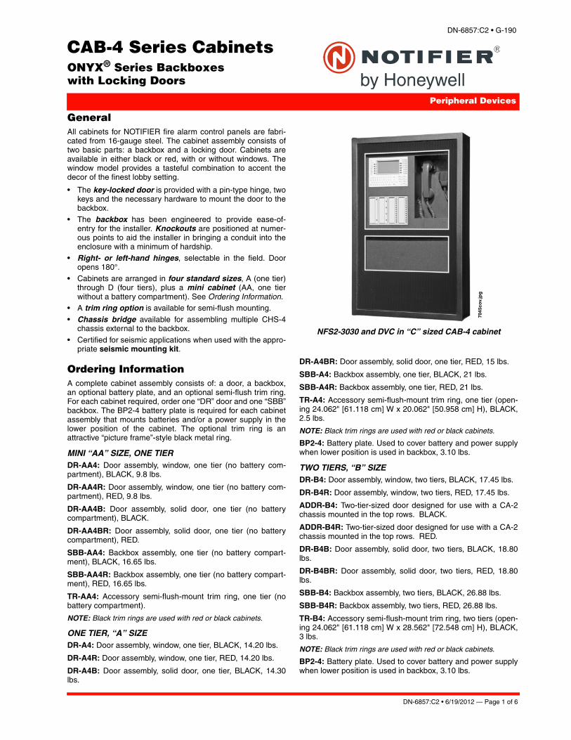
NFS2-3030 and DVC in “C” sized CAB-4 cabinet
GeneralAll cabinets for NOTIFIER fire alarm control panels are fabri-cated from 16-gauge steel. The cabinet assembly consists oftwo basic parts: a backbox and a locking door. Cabinets areavailable in either black or red, with or without windows. Thewindow model provides a tasteful combination to accent thedecor of the finest lobby setting.
• The key-locked door is provided with a pin-type hinge, twokeys and the necessary hardware to mount the door to thebackbox.
• The backbox has been engineered to provide ease-of-entry for the installer. Knockouts are positioned at numer-ous points to aid the installer in bringing a conduit into theenclosure with a minimum of hardship.
• Right- or left-hand hinges, selectable in the field. Dooropens 180°.
• Cabinets are arranged in four standard sizes, A (one tier)through D (four tiers), plus a mini cabinet (AA, one tierwithout a battery compartment). See Ordering Information.
• A trim ring option is available for semi-flush mounting.
• Chassis bridge available for assembling multiple CHS-4chassis external to the backbox.
• Certified for seismic applications when used with the appro-priate seismic mounting kit.
Ordering InformationA complete cabinet assembly consists of: a door, a backbox,an optional battery plate, and an optional semi-flush trim ring.For each cabinet required, order one “DR” door and one “SBB”backbox. The BP2-4 battery plate is required for each cabinetassembly that mounts batteries and/or a power supply in thelower position of the cabinet. The optional trim ring is anattractive “picture frame”-style black metal ring.
MINI “AA” SIZE, ONE TIERDR-AA4: Door assembly, window, one tier (no battery com-partment), BLACK, 9.8 lbs.
DR-AA4R: Door assembly, window, one tier (no battery com-partment), RED, 9.8 lbs.
DR-AA4B: Door assembly, solid door, one tier (no batterycompartment), BLACK.
DR-AA4BR: Door assembly, solid door, one tier (no batterycompartment), RED.
SBB-AA4: Backbox assembly, one tier (no battery compart-ment), BLACK, 16.65 lbs.
SBB-AA4R: Backbox assembly, one tier (no battery compart-ment), RED, 16.65 lbs.
TR-AA4: Accessory semi-flush-mount trim ring, one tier (nobattery compartment).
NOTE: Black trim rings are used with red or black cabinets.
ONE TIER, “A” SIZEDR-A4: Door assembly, window, one tier, BLACK, 14.20 lbs.
DR-A4R: Door assembly, window, one tier, RED, 14.20 lbs.
DR-A4B: Door assembly, solid door, one tier, BLACK, 14.30lbs.
DR-A4BR: Door assembly, solid door, one tier, RED, 15 lbs.
SBB-A4: Backbox assembly, one tier, BLACK, 21 lbs.
SBB-A4R: Backbox assembly, one tier, RED, 21 lbs.
TR-A4: Accessory semi-flush-mount trim ring, one tier (open-ing 24.062" [61.118 cm] W x 20.062" [50.958 cm] H), BLACK,2.5 lbs.
NOTE: Black trim rings are used with red or black cabinets.
BP2-4: Battery plate. Used to cover battery and power supplywhen lower position is used in backbox, 3.10 lbs.
TWO TIERS, “B” SIZEDR-B4: Door assembly, window, two tiers, BLACK, 17.45 lbs.
DR-B4R: Door assembly, window, two tiers, RED, 17.45 lbs.
ADDR-B4: Two-tier-sized door designed for use with a CA-2chassis mounted in the top rows. BLACK.
ADDR-B4R: Two-tier-sized door designed for use with a CA-2chassis mounted in the top rows. RED.
DR-B4B: Door assembly, solid door, two tiers, BLACK, 18.80lbs.
DR-B4BR: Door assembly, solid door, two tiers, RED, 18.80lbs.
SBB-B4: Backbox assembly, two tiers, BLACK, 26.88 lbs.
SBB-B4R: Backbox assembly, two tiers, RED, 26.88 lbs.
TR-B4: Accessory semi-flush-mount trim ring, two tiers (open-ing 24.062" [61.118 cm] W x 28.562" [72.548 cm] H), BLACK,3 lbs.
NOTE: Black trim rings are used with red or black cabinets.
BP2-4: Battery plate. Used to cover battery and power supplywhen lower position is used in backbox, 3.10 lbs.

Page 2 of 6 — DN-6857:C2 • 6/19/2012
THREE TIERS, “C” SIZEDR-C4: Door assembly, window, three tiers, BLACK, 20.75 lbs.
DR-C4R: Door assembly, window, three tiers, RED, 20.75 lbs.
ADDR-C4: Three-tier-sized door designed for use with a CA-2chassis mounted in the top rows. BLACK.
ADDR-C4R: Three-tier-sized door designed for use with a CA-2 chassis mounted in the top rows. RED.
DR-C4B: Door assembly, solid door, three tiers, BLACK, 23.45lbs.
DR-C4BR: Door assembly, solid door, three tiers, RED, 23.45lbs.
SBB-C4: Backbox assembly, three tiers, BLACK, 32.60 lbs.
SBB-C4R: Backbox assembly, three tiers, RED, 32.60 lbs.
TR-C4: Accessory semi-flush-mount trim ring, three tiers(opening 24.062" [61.118 cm] W x 37.187" [94.455 cm] H),BLACK, 3.50 lbs.
NOTE: Black trim rings are used with red or black cabinets.
BP2-4: Battery plate. Used to cover battery and power supplywhen lower position is used in backbox, 3.10 lbs.
FOUR TIERS, “D” SIZEDR-D4: Door assembly, window, four tiers, BLACK, 23.95 lbs.
DR-D4R: Door assembly, window, four tiers, RED, 23.95 lbs.
ADDR-D4: Four-tier-sized door designed for use with a CA-2chassis mounted in the top rows. BLACK.
ADDR-D4R: Four-tier-sized door designed for use with a CA-2chassis mounted in the top rows. RED.
DR-D4B: Door assembly, solid door, four tiers, BLACK, 28.40lbs.
DR-D4BR: Door assembly, solid door, four tiers, RED, 28.40lbs.
SBB-D4: Backbox assembly, four tiers, BLACK, 40 lbs.
SBB-D4R: Backbox assembly, four tiers, RED, 40 lbs.
TR-D4: Accessory semi-flush-mount trim ring, four tiers (open-ing 24.062" [61.118 cm] W x 45.812" [116.363 cm] H), BLACK,3.80 lbs.
NOTE: Black trim rings are used with red or black cabinets.
BP2-4: Battery plate. Used to cover battery and power supplywhen lower position is used in backbox, 3.10 lbs.
ACCESSORIESADP-4B: Annunciator dress panel.
CAB-BM: For use with “B” sized cabinets in Marine applica-tions. See DN-60688 for more information.
CB-1: Chassis bridge. Provides a bridge between CHS Serieschassis.
DP-1B: Blank dress panel, covers one CAB-4 tier, BLACK.
SEISKIT-CAB: Seismic mounting kit. Required for seismic-certified applications with NFS2-3030, NFS2-640, and NFS-320SYS. Includes battery bracket for two 26 AH batteries.
VP-2B: Ventilator panel.
WC-2: Wire channel. Provides a pair of wire trays to neatlyroute wiring between CHS chassis.
Agency Listings and ApprovalsThese listings and approvals below apply to the CAB-4 SeriesCabinets. In some cases, certain modules or applications maynot be listed by certain approval agencies, or listing may be inprocess. Consult factory for latest listing status.
• UL Listed: S635
• ULC Listed: S635 • MEA: 317-01-E, 345-02-E• CSFM: 7165-0028:0243 (NFS2-640), 7165-0028:0224
(NFS2-3030)• FM approved
• FDNY: COA# 6085, COA# 6098CAB-4 Series cabinets with SEISKIT-CAB comply with seismicrequirements of IBC 2000, IBC 2003, IBC 2006, IBC2009, andCBC 2007.

DN-6857:C2 • 6/19/2012 — Page 3 of 6
“A” SIZECABINET
Knockouts ontop of cabinets.
6857
ko.w
mf
Cabinet Dimensions and Features
cab-a4-2003.wmf
Keyholedimensions
CAB4keyhole.wmf
Height of mounting boltafter installation

Page 4 of 6 — DN-6857:C2 • 6/19/2012
“AA” SIZECABINET
“B” SIZECABINET
cab-b4-2003.wmf
cab-b4-2003.wmf
“C” SIZECABINET
cab-c4-2003.wmf

DN-6857:C2 • 6/19/2012 — Page 5 of 6
“D” SIZECABINET
cab-d4-2003.wmf
“D” sized cabinetwith solid door.Solid door option availableon all sizes in black or red.
6897
d4b.
wm
f
The BP2-4 Battery Platecovers the Main Power Supplyand the batteries in the cabinet.Only one BP2-4 is required per cabinet unless an AA cabinet is used (no battery compartment).
6857
bp4.
wm
f

Page 6 of 6 — DN-6857:C2 • 6/19/2012
ONYX® and NOTIFIER® are registered trademarks of HoneywellInternational Inc. ©2012 by Honeywell International Inc. All rights reserved. Unauthorized useof this document is strictly prohibited.
This document is not intended to be used for installation purposes. We try to keep our product information up-to-date and accurate.
We cannot cover all specific applications or anticipate all requirements. All specifications are subject to change without notice.
For more information, contact Notifier. Phone: (203) 484-7161, FAX: (203) 484-7118.www.notifier.com
Made in the U.S. A.

DVC SeriesDigital Voice Command DVC-EM
Voice Control Systems
DN-7045:I • C-7
GeneralThe DVC is the heart of an integrated, full-featured Audio Command Center. The DVC Digital Voice Command combines the capabilities of a powerful digital audio processor, an event-driven audio message generator, and a router. Designed for use with Digital Audio Loop (DAL) devices such as DAA2, DAX and DAA series digital amplifiers as well as the DS-DB, each DVC supports a dedicated audio network with up to eight channels of audio, five channels of firefighter telephone com-munications, and control and supervision for up to 32 DAL devices. The DVC has two wire digital audio ports to connect to wire DAL segments. Either or both ports may be converted to multi-mode fiber or single-mode fiber using fiber option modules. Larger audio systems incorporating hundreds of amplifiers can be created by networking additional DVC units via NOTI•FIRE•NET™.
The DVC may be networked with ONYX® Series panels via NOTI•FIRE•NET with an NCA-2, or with an NFS2-3030(running in network monitor mode). A DVC can be connected directly with a single NFS2-640 or NFS2-3030 Fire Alarm Con-trol Panel (FACP) to create a standalone integrated audio solu-tion as well. Refer to the DVC manual for details.
When used as an Audio Command Center with Emergency Paging capability, the optional DVC-KD Keypad Display is required.
NOTE: Unless otherwise noted, the term “DVC” refers to the DVC-EM.
Features• Programmable from NUP port using VeriFire® Tools.• Up to 32 minutes of standard quality or 4 minutes of high
quality digital audio storage of user-selected/created mes-sages and tones. Supports twisted-pair wire media. Sup-ports single- and multi-mode fiber-optic media when used with fiber option modules.
• 4-channel analog audio supported with optional DVC-AO• Up to 1000 audio sequences.• Message prioritization.
• Equations support flexible programming for distribution of messages.
• Electrically isolated digital audio ports for direct connection with up to 32 Digital Audio Loop (DAL) devices. Style 4 or 7 configurations supported.
• Optional DS-RFM, DS-FM, and DS-SFM fiber modules may be used to convert one or both Digital Audio Ports for oper-ation with single-mode or multi-mode fiber.
• DCC (Display and Control Center) capabilities when used with optional DVC-KD.
• Firefighters’ Telephone Communications to local FFT riser on DVC, 32 local DAL device FFT risers, and FFT communication to additional command stations via NOTI•FIRE•NET.
• Local paging microphone option.
• Remote microphone options.• Optional Digital Voice Command Remote Paging Unit
(DVC-RPU), or DVC-RPU mode.
• Broad All-Call functionality when used with DVC-KD (DVC-Keyboard Display): All Call, Page Active Evac Areas, Page Active Alert Areas, Page Inactive Areas.
• Auxiliary input for 12 Vp-p analog low-level audio sources. Includes user audio level adjustment feature.
• Auxiliary input accepts external audio sources such as tele-phone paging or background music. High impedance input accepts 600 ohm, line level, 1.0 VRMS, or 1.41 Vp-p low level audio. Selectable AGC, user control of audio level, and audio supervision are supported.
• Associated NCA-2, or NFS2-3030 (programmed for net-work monitor mode) supports NOTI•FIRE•NET applica-tions.
• Multiple audio command centers supported via NOTI•FIRE•NET.
• Distribution of one channel of standard-level paging audio on NOTI•FIRE•NET.
• Three standalone, non-network mode options:– NFS2-3030 (NUP to NUP) digital and analog.– NFS2-640 (NUP to NUP) analog audio only.
– NFS2-640 with NCA-2 (NUP to NUP to NUP) digital and analog.
• Push-to-talk relay, or logic argument. • Isolated alarm bus input, to be used for backup activation of
alarm messages in the event network communication is lost.
Installation OptionsThe DVC provides flexible configurations based on one-row or two-row chassis options that mount into size “B”, “C”, or “D” CAB-4 Series cabinets.
DVC Shown using CA-2 mounting option,
SBB-C4, and ADDR-C4 door.
7045
cov.
jpg
DN-7045:I • 12/20/2013 — Page 1 of 4

The CA-2 supports a DVC, paging microphone, optional FFT telephone, and mounting location for an NCA-2 or NFS2-3030D CPU. The ADDR audio door series can be used when a CA-2 is mounted in the top two rows. The CA-1 supports aDVC and an optional microphone in a single row. For firefight-ers’ telephone applications with a CA-1, the CFFT-1 can be mounted in the row below the CA-1.
NOTE: For NFS2-640/DVC applications using DAL devices, anNCA-2 is required to annunciate DAL device events.Refer to the DVC System Audio Product Application Guide(part number M-AG-DVC) for more details on DVC applica-tions).
Specifications• 24 VDC power (TB1): 24 VDC, 1.0 A, non-resettable,
power-limited by the source. Recommended wiring: 14 to 18 AWG (2.08 to 0.821 mm²) twisted-pair.
• Digital audio ports, wire media, A and B (TB2, TB3): Maximum distance per segment is 1900 feet (579.12 m) on Belden 5320UJ (18 AWG, TP) FPL cable: 18 AWG (0.821 mm²) twisted-pair, foil-shielded, power-limited. Consult wir-ing documentation provided in document P/N 52916ADD:C Addendum to DVC and DAA Manuals.
• Digital audio ports, single- and multi-mode fiber-optic media: (See notes below)– DS-FM and DS-SFM fiber option module (no direct
DAA connection): • 6.5dB maximum attenuation for multi-mode with 50/125
micrometer cable @ 1310 nm.• 10dB maximum attenuation for multi-mode with 62.5/
125 micrometer cable @ 1310 nm.• 30dB maximum attenuation for single-mode with 9/125
micrometer cable @ 1310 nm.– DS-SFM (single-mode fiber DAA connection):
• 17dB maximum attenuation for single-mode with 9/125 micrometer cable at 1310 nm going from the DS-SFM to the fiber DAA.
• 4dB maximum attenuation for single-mode with 9/125 micrometer cable going from the fiber DAA to the DS-SFM.
• 12dB minimum attenuation going from the DS-SFM tothe fiber DAA.
– DS-RFM (multi-mode fiber DAA connection): • Attenuation going from the fiber DAA to the DS-RFM:
• 2dB maximum attenuation for multi-mode with 50/125 micrometer cable @ 850 nm for the DS-RFM.
• 4dB maximum attenuation for multi-mode with 62/5/125 micrometer cable @ 850 nm for the DS-RFM.
• Attenuation going from the fiber DS-RFM to the fiber DAA:
• 12dB minimum* attenuation, 16dB for both cable types.Notes: 1. If the length of the fiber run results in an attenuation of less than 12dB, a suitable attenuator must be used.2. ST® Style connection required at DAA end of any fiber connection. LC style connectors are required for the DS-FM, DS-RFM, and DS-SFM.
• Auxiliary input A (AUX A, TB4): Signal strength from low-level analog audio input: maximum 1.0 VRMS, or 1.41 Vp-p. Optional supervision is selectable through programming. Recommended wiring: 18 AWG (0.821 mm²) twisted-pair; max. 14 AWG (2.08 mm²). Auxiliary input must be in the same room as the DVC.
• Auxiliary input B (AUX B, TB14): Signal strength from low-level analog audio input: 12 Vp-p nominal, 15 Vp-p maxi-
mum. Optional supervision is selected through program-ming. Recommended wiring: 14 to 18 AWG (2.08 to 0.821 mm²) twisted-pair.
• Remote microphone interface (TB9): Recommended wir-ing: 14 to 18 AWG (2.08 to 0.821 mm²) twisted-pair. Power-limited. Maximum distance between remote microphone and DVC: 1000 feet (300 m).
• Push-to-talk interface (TB10): Dry contact. Recom-mended wiring: 14 to 18 AWG (2.08 to 0.821 mm²) twisted-pair.
• Alarm bus (TB12): Power-limited by source. Recom-mended wiring: 14 to 18 AWG (2.08 to 0.821 mm²) twisted-pair.
• FFT riser (TB13): Power-limited output. Class A (Style Z) or Class B (Style Y) operation. Style Y two-wire connections require a 3.9K ohm, 1/2 watt resistor (P/N K-3.9K). Maxi-mum wiring resistance (including individual telephone zone to last handset) permitted is 50 ohms, 10,000 feet (3048 m) maximum wiring distance at 12 AWG (3.31 mm²) to last handset.
• Optional DVC-AO analog audio output circuits (TB5, TB6, TB7, and TB8): Supervised, power-limited outputs. Signal strength: +12 Vp-p nominal, +15 Vp-p maximum. Rec-ommended wiring: 18 AWG (0.821 mm²) twisted-pair; max. 14 AWG (2.08 mm²). Maximum impedance: 66 ohms.
Standards and CodesThe Digital Voice Command DVC and DVC-EM comply with the following standards:
• NFPA 72 2002 National Fire Alarm Code.
• Underwriters Laboratories Standards UL 864, 9th edition, and UL 2572.
• Underwriters Laboratories of Canada (ULC) ULC-S527-99 Standard of Control Units for Fire Alarm Systems.
Listings and ApprovalsThe listings and approvals below apply to the DVC and DVC-EM Digital Voice Command. In some cases, certain modules may not be listed by certain approval agencies, or listing may be in process. Consult factory for latest listing status.
• UL Listed: S635.
• ULC Listed: S635.• FM Approved.• CSFM: 7165-0028:0224 (NFS2-3030); 7165-0028:0243
(NFS2-640).
• FDNY: COA#6114 (NFS2-3030): COA#6085, COA#6121 (NFS2-640).
• City of Chicago approved: High Rise, Class 1, Class 2 (NFS2-3030, NFS2-640, NCA-2).
• City of Denver approved (NFS2-3030).• PSB Corporation approved (Singapore) (NFS2-3030).
Product Line InformationDVC-EM: Digital Voice Command, digital audio processor with message storage for up to 32 minutes of standard quality (4 minutes at high quality) digital audio. Supports twisted-pair wire media. Options: DS Fiber modules, DVC-RPU.
DVC-RPU: Digital Voice Command Remote Paging Unit. Includes the keypad/display. Supports twisted-pair wire media; use DS fiber modules for fiber media. See DN-60726.
DVC-KD: Keypad for local annunciation and controls; status LEDs and 24 user-programmable buttons.
Page 2 of 4 — DN-7045:I • 12/20/2013

DVC-AO: Optional DVC Analog Output board provides four analog output circuits for use with AA or XPIQ Series amplifi-ers. Four-channel operation supported.
CA-1: Chassis, occupies one tier of a CAB-4 Series enclosure. The left side accommodates one DVC and a DVC-KD (optional); and the right side houses a CMIC-1 microphone and its well (optional).
CMIC-1: Optional microphone and microphone well assembly used with the CA-1 chassis.
CFFT-1: The CFFT-1 Chassis for Firefighters’ Telephone mounts in the row directly under a DVC that is mounted in a CA-1 single row chassis. The CFFT-1 includes one FFT hand-set. The DP-CFFT Dress Plate (separately ordered, required) has one open position for mounting an ACS annunciator or a BMP-1 Blank Module Plate.
CA-2: Chassis assembly, occupies two tiers of a CAB-4 Series enclosure. The left side accommodates one DVC mounted on a half-chassis and one NFS2-3030 or NCA-2 mounted on a half-chassis. The right side houses a microphone/handset well. The CA-2 assembly includes a microphone. DPA-2B dress plate is required (below); the VP-2B Vent Plate is also required for top row configurations. ADDR Series doors with two-tier visibility are available for use with the CA-2 configura-tion: ADDR-B4, ADDR-C4, ADDR-D4 (below).
DPA-2B: Dress plate required for CA-2 chassis assembly.
VP-2B: Vent plate required for cabinet configurations where the DPA-2B is used for the top two row position.
TELH-1: Firefighters’ Telephone Handset for use with the DVC when mounted in the CA-2 chassis. Order separately.
ADDR-B4: Two-tier-sized door designed for use with a CA-2 chassis mounted in the top rows. ADDR Series doors are sim-ilar to CAB-4 Series “DR” doors, but a clear window space exposes the top two tiers of the CAB-4 enclosure. Use an SBB-B4 backbox with the ADDR-B4. See DN-6857.
ADDR-C4: Three-tier-sized door designed for use with a CA-2 chassis mounted in the top rows. ADDR Series doors are sim-ilar to CAB-4 Series “DR” doors, but a clear window space exposes the top two tiers of the CAB-4 enclosure. Use an SBB-C4 backbox with the ADDR-C4. See DN-6857.
ADDR-D4: Four-tier-sized door designed for use with a CA-2 chassis mounted in the top rows. ADDR Series doors are sim-ilar to CAB-4 Series “DR” doors, but a clear window space exposes the top two tiers of the CAB-4 enclosure. Use an SBB-D4 backbox with the ADDR-D4. See DN-6857.
DPA-1: Dress panel, can be used with the CA-1 chassis when configured with a DVC, DVC-KD, and CMIC-1.
DPA-1A4: Dress panel, used with the CA-1 chassis when the CMIC-1 is not used. Provides mounting options on right two bays for two ACS annunciators, or for blank plates.
ACT-4: Audio-coupling transformer. Used to electronically iso-late DVC-AO analog risers.
ACT-25, ACT-70: Audio-coupling transformers for 25V and 70V high-level audio. Used to isolate and convert high-level audio to low-level, supporting applications with large numbers of analog amplifiers.
DAX-3525(E)/DAX-3570(E): 35W, 25 or 70.7VRMS. Digital audio amplifiers with charging power supply and 2 Class B or 1 Class A output, shipped mounted on chassis. Options: BDA-25/70 backup amplifier, DS Fiber modules.
DAX-5025(E)/DAX-5070(E): 50W, 25 or 70.7VRMS. Digital audio amplifiers with power supply and 2 Class B or 1 Class A output, shipped mounted on chassis. Options: BDA-25/70 backup amplifier, DS Fiber modules.
DAA2-5025(E)/DAA2-5070(E): 50W, 25 or 70.7VRMS. Digital audio amplifiers with charging power supply and 4 Class B or 2 Class A outputs, shipped mounted on chassis. RM-1 port, FFT port, Aux audio port. Supports optional BDA for backup ampli-fier or 2-channel operation, and DS Fiber modules.
DAA2-7525(E): 75W, 25VRMS. Digital audio amplifiers with power supply and 4 Class B or 2 Class A outputs, shipped mounted on chassis. RM-1 port, FFT port, Aux audio port. Supports optional BDA for backup amplifier or 2-channel oper-ation, and DS Fiber modules.
DS-DB: Digital Series Distribution Board, provides bulk ampli-fication capabilities to the DVC while retaining digital audio dis-tribuition capabilities. Can be configured with up to four DS-AMPs, supplying high-level risers spread throughout an instal-lation. See DN-60565.
DS-AMP/E: 125W, 25 VRMS, or 100W, 70VRMS. 70VRMS requires DS-XF70V step-up transformer. Digital Series Ampli-fier, part of the DS-DB system. See DN-60663.
DS-BDA: Digital Series Backup Digital Amplifier, 25 or 70VRMS, can be configured to act as a one-to-one backup for DS-AMP/E amplifiers. Can also be programmed to provide a second audio channel for a DS-AMP. See DN-60663.
BDA-25, BDA-70: Backup Digital Amplifier, 25 or 70.7VRMS, can be configured to act as a one-to-one backup for DAX and DAA2 series amplifiers. For DAA2 Series only, supports alter-native second channel operation.
DS-RFM, DS-FM, DS-SFM: Fiber conversion modules for DVC, DS-DB distribution board, and DAX and DAA2 Series amplifiers. See DN-60633.
DAA Series Digital Audio Amplifiers: Legacy DAA Series amplifiers are compatible with DVC systems running SR4.0. For DAA-50 series amplifiers, see DN-7046. For DAA-7525 Series, see DN-60257.
– DAA-5025: 50W, 25Vrms Digital Audio Amplifier assem-bly with DAA-PS power supply board, shipped mounted to its chassis. Supports twisted-pair wire media. (For multi-mode fiber-optic media order DAA-5025F. For single-mode fiber-optic media order DAA-5025SF.)
– DAA-5070: 50W, 70.7Vrms Digital Audio Amplifier assembly with DAA-PS power supply board, shipped mounted to its chassis. Supports twisted-pair wire media. (For multi-mode fiber-optic media order DAA-5070F. For single-mode fiber-optic media order DAA-5070SF.)
– DAA-7525: 75W, 25Vrms Digital Audio Amplifier assem-bly with DAA-PS power supply board. Shipped mounted to its chassis (no battery charger on DAA-7525 power supply board). Supports twisted-pair wire media. (For multi-mode fiber-optic media order DAA-7525F. For sin-gle-mode fiber-optic media order DAA-7525SF.)
SEISKIT-CAB: Seismic kit for CAB-4 series cabinets. Includes battery bracket for two 26AH Power Sonic batteries and TELH-1 telephone handset strap. See document 53829.
SEISKIT-DAA: Seismic kit for DAA, DAA2 and DAX series amplifiers, required when using CHS-BH1 chassis. Includes battery bracket for two 12AH Power Sonic batteries. See docu-ment 53851.
DN-7045:I • 12/20/2013 — Page 3 of 4

ONYX®, NOTIFIER®, and VeriFire® are registered trademarks of and NOTI•FIRE•NET™ is a trademark of Honeywell International Inc. ST® is a registered trademark of AT&T. ©2013 by Honeywell International Inc. All rights reserved. Unauthorized use of this document is strictly prohibited.
Page 4 of 4 — DN-7045:I • 12/20/2013
This document is not intended to be used for installation purposes. We try to keep our product information up-to-date and accurate.
We cannot cover all specific applications or anticipate all requirements. All specifications are subject to change without notice.
For more information, contact Notifier. Phone: (203) 484-7161, FAX: (203) 484-7118.www.notifier.com
Made in the U.S. A.

DN-60229:C • 01/16/2012 — Page 1 of 4
EQ CabinetONYX® Series Equipment Backboxeswith Ventilated Locking Doors
Peripheral Devices
DN-60229:C
General EQ Series cabinets provide an effective solution for applica-tions that require distributed components such as power sup-plies, amplifiers, and multiple I/O modules. The EQ Seriesprovides superior ventilation for devices such as amplifiers andfield power supplies, ample room for wire or fiber-optic mediabetween each row, and a space efficient package that allowsfor the consolidation of multiple system components in a singleenclosure.
Equipment cabinets use a perforated blank door for enhancedventilation, and do not support the mounting of backboxmounted dress plates. Therefore these cabinets are not appro-priate for equipment that would be normally accessed by asystem operator such as control equipment, annuniciators, orremote microphones.
EQ cabinets share the same external dimensions as the famil-iar CAB-4 Series cabinets. EQ Series cabinets differ in thatthey do not include a separate battery row. See illustrationsbelow for examples of EQ cabinet row spacing.
Specifications • Equipment cabinets are fabricated from 16-gauge steel.
The cabinet assembly consists of two basic parts: a back-box and a locking door. Cabinets are available in black.
• The key-locked door is provided with a pin-type hinge, twokeys and the necessary hardware to mount the door to thebackbox.
• The backbox has been engineered to provide ease-of-entryfor the installer. Knockouts are positioned at numerouspoints to aid the installer in bringing a conduit into theenclosure with a minimum of hardship.
• Right- or left-hand hinges, selectable in the field. Dooropens 180°.
• Cabinets are arranged in 3 standard sizes, B (two tiers)through D (four tiers). See Ordering Information.
• Trim ring options are available for semi-flush mounting.
Equipment Compatible for Use in EQ Series Cabinets • DAA2 Series Amplifiers• DAX Series Amplifiers
• DS-DB Digital Series Distribution Board• DS-AMP Digital Series Amplifier• DAA-50 Series Amplifiers
• DAA-75 Series Amplifiers• AA-30 Audio Amplifiers• AA-100 Audio Amplifiers
• AA-120 Audio Amplifiers• ACPS-610 Power Supply• AMPS-24 Power Supply
• HPPF8/8CM Power Supply• HPPF12/12CM Power Supply• XP6-C Modules
• XP6-MA Modules
• XP6-R Modules• XP10-MA Modules
Agency Listings and ApprovalsThese listings and approvals below apply to the EQ cabinet. Insome cases, certain modules or applications may not be listedby certain approval agencies, or listing may be process. Con-sult factory for latest listing status.
• UL Listed: S635.
• ULC Listed: S635.• CSFM: 7165-0028:0243 (NFS2-640), 7165-0028:0224
(NFS2-3030). • FDNY: COA#6067 (NFS2-640), COA#6065 (NFS2-3030),
COA#6073.
Ordering InformationA complete cabinet assembly consists of: a door, a backbox,and an optional semi-flush trim ring. For each cabinetrequired, order one "EQDR" door and one "EQBB" backbox.
The optional trim ring is an attractive "picture frame"-styleblack metal ring.
TWO TIERS, "B" SIZE:EQDR-B4: Door assembly, vented door, two tiers, BLACK.
EQBB-B4: Backbox assembly, two tiers, BLACK.
TR-B4: Semi-flush-mount trim ring, two tiers.
THREE TIERS, "C" SIZE:EQDR-C4: Door assembly, vented door, three tiers, BLACK.
EQBB-C4: Backbox assembly, three tiers, BLACK.
TR-C4: Semi-flush-mount trim ring, three tiers.
EQ
Cab
.jpg

Page 2 of 4 — DN-60229:C • 01/16/2012
FOUR TIERS, "D" SIZE:EQDR-D4: Door assembly, vented door, four tiers, BLACK.
EQBB-D4: Backbox assembly, four tiers, BLACK.
TR-D4: Semi-flush-mount trim ring, four tiers.
45-7/8"(116.52)
37-1/32"(94.06)
45-3/4"(116.21)
24-1/8" (61.28) 16" (40.64)(10.16)
4"
24" (60.96)1-5/8"(4.13)
2-1/4"(5.72)
2-1/4"(5.72)
5/16" dia.(0.79)
5/16" dia.(0.79)
19-1/2" (49.53)
(cm)
5-5/32"(13.1)
2-1/16"(5.24)
2-5/8"(6.604)
Top knockout: Inner 1.375" (3.49)Outer 1.750" (4.45)
Four lower knockoutsInner 0.875" (2.22)Outer 1.125" (2.86)
11-1/2")(29.21
1-7/8”(4.699)
2")(5.081”
)(2.54 11")(27.94
11")(27.94
CABINET DRAWINGS AND FEATURES
eqcab-d.wmf
EQDR-D4 EQBB-D4 Box

DN-60229:C • 01/16/2012 — Page 3 of 4
24-1/8" (61.28) 16" (40.64)(10.16)
4"
24" (60.96)1-5/8"(4.13)
37-1/4"(94.62)
28-3/32"(71.36)
37-1/8"(94.3)
2-1/4"(5.72)
2-1/4"(5.72)
5-5/32")(13.1
2-1/16”)(5.2324
11-1/2")(29.21
5/16" dia.(0.79)
5/16" dia.(0.79)
19-1/2" (49.53)
(cm)
2-5/8”(6.604)
Top knockout: Inner 1.375" (3.49)Outer 1.750" (4.45)
Three lower knockoutsInner 0.875" (2.22)Outer 1.125" (2.86)
1-7/8”(4.699)
2")(5.081”
)(2.54 11")(27.94
28-5/8")(72.71
19-3/4”)(50.24
2-1/4" (5.72)
28-1/2")(72.39
2-1/4")(5.72
24-1/8" (61.28) 16" (40.64)(10.16)
4"
24" (60.96)1-5/8"
)(4.13
5-5/32")(13.1
2-1/16”)(5.2324
11-1/2”)(29.21
2")(5.085/16" dia.
(0.79)5/16" dia.
(0.79)
19-1/2" (49.53)
(cm)
2-5/8”(6.604)
Two lower knockoutsInner 0.875" (2.22)Outer 1.125" (2.86)
Top knockout: Inner 1.375" (3.49)Outer 1.750" (4.45)
1-7/8”(4.699)
1”)(2.54
60229cab2.wmf
eqcab-c.wmf
EQDR-C4 EQBB-C4 Box
EQDR-B4 EQBB-B4 Box

Page 4 of 4 — DN-60229:C • 01/16/2012
Notifier® is a registered trademark of Honeywell International Inc. ©2012 by Honeywell International Inc. All rights reserved. Unauthorized useof this document is strictly prohibited.
This document is not intended to be used for installation purposes. We try to keep our product information up-to-date and accurate.
We cannot cover all specific applications or anticipate all requirements. All specifications are subject to change without notice.
For more information, contact Notifier. Phone: (203) 484-7161, FAX: (203) 484-7118.www.notifier.com
Made in the U.S. A.
45-3/4"(116.21)
5-5/32"(13.1)
2-1/16"(5.24)
2-9/16"(6.51)
Top knockout: Inner 1.375" (3.49)Outer 1.750" (4.45)
Four lower knockoutsInner 0.875" (2.22)Outer 1.125" (2.86)
11-1/2")(29.21
1-17/20”(4.699)
2")(5.081”
)(2.54 11")(27.94
11")(27.94
6022
9sid
e.w
mf
6857
ko.w
mf
cab4keyhole.wm
f
Mounting Hole
Top View of Backbox
Side View of Backbox(EQBB-D4)

DN-6862:D • 2/28/17 — Page 1 of 4
ACS Series AnnunciatorsONYX® Series ACM/AEM-24AT, ACM/AEM-48A
DN-6862:D • D-95
Annunciator Control Systems
GeneralThe ONYX® Series ACS Annunciators provide a modular lineof products for annunciation and control of the NOTIFIERONYX® Series Intelligent Fire Alarm Control Panels, NetworkControl Annunciators, and NOTIFIER’s legacy addressablepanels. The ACS line provides arrays of LEDs to indicate pointstatus and, in some versions, switches to control the state ofoutput circuits. These ACS units use a serial interface and maybe located at distances of up to 6,000 feet (1,828.8 meters)from the panel.
Features• Speaker control mode for use with XPIQ and the following
panels: NFS2-3030, NFS2-640, NFS-320(C) and NFS-320SYS. Enables the ACS to control operation of groups ofmulti-channels mapped to groups of multi-speakers.
• Compatible with existing annunciators.
• Color-programmable LEDs.• On-board end-of-line resistors can be enabled/disabled by
setting a switch.• Alarm/Circuit On and Trouble LED per-point option or more
dense Alarm-only option.• Touch-pad control switch option for remote control of sys-
tem relays; or silence, reset, and evacuate.• LEDs may be programmed to display status of indicating
circuits or control relays as well as system status condi-tions.
• System Trouble LED indicator.• On-Line/Power LED indicator.• Alarm and trouble resound with flash of new conditions.
• Local sounder for both alarm and trouble conditions withsilence/acknowledge button (program options).
• May be powered by 24 VDC from the panel or by remotepower supplies.
• Microprocessor-controlled electronics, fully supervised.• Slip-in custom labels, lettered with standard typewriter or
LabelEase program.• Plug-in terminal blocks for ease of installation and service.
ConstructionThe ACS modules are provided in two basic controller mod-ules, each with its expander module. The ACM-24AT provides24 annunciation and control points per module, each with ared, green, or yellow Alarm/Circuit On LED, a yellow TroubleLED, and a touch-key switch. The ACM-48A provides 48annunciation points per module, each with a red, green, or yel-low Alarm/Circuit On LED (for annunciating control relays, theLED indicates ON/OFF).
On the ACM-24AT, each LED point is individually color-pro-grammable. On ACM-48A, each column of 24 LED points canbe color-configured using a DIP switch.
Temperature and humidity ranges: This system meetsNFPA requirements for operation at 0°C to 49°C (32°F to120°F); and at a relative humidity (noncondensing) of 85% at30°C (86°F) per NFPA, and 93% ± 2% at 32°C ± 2°C (89.6°F ±1.1°F) per ULC. However, the useful life of the system’s
standby batteries and the electronic components may beadversely affected by extreme temperature ranges and humid-ity. Therefore, it is recommended that this system and allperipherals be installed in an environment with a nominal roomtemperature of 15°C to 27°C (60°F to 80°F).
InstallationThe ACS Series annunciator and control subsystems usemodular hardware assemblies which allow the custom configu-ration of the annunciator panel to fit the individual job require-ments.
Standard backboxes and mounting hardware schemes, includ-ing special remote cabinets, allow the annunciators to be con-structed and configured with other system components.
When used with the NFS2-3030, NFS2-640, NFS-320 or leg-acy panels, the ACS modules can be used for manual selec-tion of speaker and telephone circuits. In this application, theyare typically mounted in the main control near the microphoneand telephone handset.
For remote annunciation applications, the modules are typi-cally mounted in special ABF or ABS boxes. Control switch keylocks (AKS-1B) are available.
Communication between the ACS Series annunciators and thehost Fire Alarm Control Panel is made through an EIA-485multi-drop loop, eliminating the need for costly wiringschemes. Four wires are required, two for the EIA-485 com-munications (twisted pair), and two for 24 VDC regulatedpower.
Retrofit of ACS Series annunciators into existing systems iseasily accomplished. Software may require upgrading, andsome legacy panels may require an interface board.
All field-wiring terminations use removable, compression-typeterminal blocks for ease of installation, wiring, and circuit test-ing.
ACM/AEM-24AT ACM/AEM-48A
6862at24.wmf 6862a48.wmf
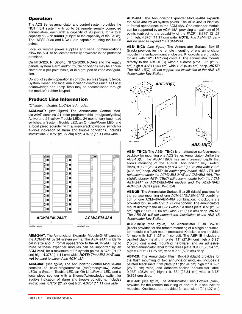
Page 2 of 4 — DN-6862:D • 2/28/17
OperationThe ACS Series annunciator and control system provides theNOTIFIER system with up to 32 remote serially connectedannunciators, each with a capacity of 96 points, for a totalcapacity of 3072 points (subject to the capability of the FACP).The NFS2-3030 and NCA-2 are capable of using the full 96points.
Local or remote power supplies and serial communicationsallow the ACS to be located virtually anywhere in the protectedpremises.
On NFS-320, NFS2-640, NFS2-3030, NCA-2 and the legacypanels, system alarm and/or trouble conditions may be annun-ciated on a per-point basis, or in a grouped or zone configura-tion.
Control of system operational controls, such as Signal Silence,System Reset, and local annunciation controls (such as LocalAcknowledge and Lamp Test) may be accomplished throughthe module’s rubber keypad.
Product Line Information“C” suffix indicates ULC-Listed model.ACM-24AT: (see figure) The Annunciator Control Mod-ule-24AT contains 24 color-programmable (red/green/yellow)Active and 24 yellow Trouble LEDs, 24 momentary touch-padswitches, a System Trouble LED, an On-Line/Power LED, anda local piezo sounder with a silence/acknowledge switch foraudible indication of alarm and trouble conditions. Includesinstructions. 8.375" (21.27 cm) high; 4.375" (11.11 cm) wide.
AEM-24AT: The Annunciator Expander Module-24AT expandsthe ACM-24AT by 24 system points. The AEM-24AT is identi-cal in size and in frontal appearance to the ACM-24AT. Up tothree of these expander modules can be supported by anACM-24AT, for a maximum of 96 system points. 8.375" (21.27cm) high; 4.375" (11.11 cm) wide. NOTE: The AEM-24AT can-not be used to expand the ACM-48A.
ACM-48A: (see figure) The Annunciator Control Module-48Acontains 48 color-programmable (red/green/yellow) ActiveLEDs, a System Trouble LED, an On-Line/Power LED, and alocal piezo sounder with a Silence/Acknowledge switch foraudible indication of alarm and trouble conditions. Includesinstructions. 8.375" (21.27 cm) high; 4.375" (11.11 cm) wide.
AEM-48A: The Annunciator Expander Module-48A expandsthe ACM-48A by 48 system points. The AEM-48A is identicalin frontal appearance to the ACM-48A. One expander modulecan be supported by an ACM-48A, providing a maximum of 96points (subject to the capability of the FACP). 8.375" (21.27cm) high; 4.375" (11.11 cm) wide. NOTE: The AEM-48A can-not be used to expand the ACM-24AT.
ABS-1B(C): (see figure) The Annunciator Surface Box-1B(black) provides for the remote mounting of one annunciatormodule in a surface-mount enclosure. Knockouts are providedfor use with 1/2" (1.27 cm) conduit. The annunciator mountsdirectly to the ABS-1B(C) without a dress plate. 8.5" (21.59cm) high x 4.5" (11.43 cm) wide x 2" (5.08 cm) deep. NOTE:The ABS-1B(C) will not support the installation of the AKS-1BAnnunciator Key Switch.
ABS-1TB(C): The ABS-1TB(C) is an attractive surface-mountbackbox for mounting one ACS Series Annunciator. Unlike theABS-1B(C), the ABS-1TB(C) has an increased depth thatallows mounting of the AKS-1B Annunciator Key Switch.Black, 9.938" (25.24 cm) high x 4.625" (11.75 cm) wide x 2.5"(6.35 cm) deep. NOTE: An earlier gray model, ABS-1TB, willnot accommodate the ACM/AEM-24AT or ACM/AEM-48A. Theslightly deeper ABS-1TB(C) will accommodate both the ACM/AEM-24AT or ACM/AEM-48A models and the ACM-16AT/ACM-32A Series (see DN-0524).
ABS-2B: The Annunciator Surface Box-2B (black) provides forthe surface mounting of one ACM-24AT/AEM-24AT combina-tion or one ACM-48A/AEM-48A combination. Knockouts areprovided for use with 1/2" (1.27 cm) conduit. The annunciatorsmount directly to the ABS-2B without a dress plate. 8.5" (21.59cm) high x 8.92" (22.66 cm) wide x 2" (5.08 cm) deep. NOTE:The ABS-2B will not support the installation of the AKS-1BAnnunciator Key Switch.
ABF-1B(C): (see figure) The Annunciator Flush Box-1B(black) provides for the remote mounting of a single annuncia-tor module in a flush-mount enclosure. Knockouts are providedfor use with 1/2" (1.27 cm) conduit. The ABF-1B includes apainted black metal trim plate [11" (27.94 cm) high x 6.25"(15.875 cm) wide], mounting hardware, and an adhesive-backed annunciator label for the dress plate. 9.938" (25.24 cm)high x 4.625" (11.75 cm) wide x 2.5" (6.35 cm) deep.
ABF-2B: The Annunciator Flush Box-2B (black) provides forthe flush mounting of two annunciator modules. Includes apainted black metal trim plate [11" (27.94 cm) high x 10.625"(26.99 cm) wide] and adhesive-backed annunciator label.9.938" (25.24 cm) high x 9.188" (23.34 cm) wide x 3.75"(9.525 cm) deep.
ABF-4B: (see figure) The Annunciator Flush Box-4B (black)provides for the remote mounting of one to four annunciatormodules. Knockouts are provided for use with 1/2" (1.27 cm)
ACM/AEM-24AT ACM/AEM-48A
6862at24.wmf 6862a48.wmf
ABS-1B(C)
ABF-1B(C)
50439d3.tif
50439d2.tif

DN-6862:D • 2/28/17 — Page 3 of 4
conduit. The flush-mounted ABF-4B includes a painted blackmetal trim plate [11" (27.94 cm) high x 19.375" (49.21 cm)wide] and an annunciator label. 9.938" (25.24 cm) high x17.75" (45.09 cm) wide x 2.5" (6.35 cm) deep.
ABF-1DB(C), ABF-2DB(C), ABS-4D(C): The ABF-1DB(C),ABF-2DB(C) and ABS-4D(C) are semi-flush-mount backboxesfor ACS Series Annunciators. The ABF-1DB(C)mounts oneannunciator module; the ABF-2DB mounts two modules; theABS-4D(C) mounts up to four modules. The ABS-4D(C)Series can also accommodate the NCA-2 network annuncia-tor, using the NCA-2 Retro Kit (NCA-2Retro); the NCA-2 ismounted in the center position with a blank plate (BMP-1)mounted on each side. Black with an attracted smoked glassdoor and keylock. The ABS-4D(C) is hinged on the bottom forstability.
• DIMENSIONS, ABF-1DB(C): Box only: 9.938" (25.24 cm)high x 4.625" (11.75 cm) wide x 2.5" (6.35 cm) deep. Door:11" (27.94 cm) high x 6" (15.24 cm) wide x 0.75" (1.9 cm)deep.
• DIMENSIONS, ABF-2DB(C): Box only: 9.938" (25.24 cm)high x 9.188" (23.34 cm) wide x 3.75" (9.525 cm) deep.Door: 11" (27.94 cm) high x 10.375" (26.35 cm) wide x0.75" (1.9 cm) deep.
• DIMENSIONS, ABS-4D(C): Box only: 11.97" (30.40 cm)high x 19.87" (50.47cm) wide x 3.50" (8.89 cm) deep. Door:11.97" (30.40 cm) high x 19.87" (50.47 cm) wide x 1.25"(3.18 cm) deep.
ABS-2D(C): This surface (or semi-flush) mount backbox isused with the ACS annunciators, the SCS series, NCA-2 andthe NCA-2 Black.
ADP-4B: The Annunciator Dress Panel-4B (black) provides forthe cabinet mounting of one to four modules. The ADP-4Bhinge-mounts to the CAB-4 Series cabinet. Modules mountdirectly to threaded studs on the dress panel.
DP-DISP: (see figure) The Dress Panel-Display allows one tofour modules to be mounted in the top row of the CAB-4Series backbox. Modules mount directly to threaded studs onthe DP-DISP.
DP-DISP2: NFS2-640 Dress Panel accommodates up to twoannunciator modules (no expanders).
BMP-1: Annunciator Blank Module is a flat black dress platethat covers unused module positions in the annunciator back-box or in the ADP-4B. 8.375" (21.27 cm) high x 4.375" (11.11cm) wide. Studs for a variety of module mounting options areavailable.
AKS-1B: The Annunciator Key Switch-1B (black) providesaccess security for the control switches on the ACM/AEM-24AT. The key switch kit includes a key and hardware formounting to the ABF-1B(C). Also included is an adhesive-backed annunciator label for use with the key switch/dressplate assembly. NOTE: The AKS-1B can only be employedwith the ABS-1TB(C).
Agency Listings and ApprovalsThe listings and approvals below apply to the ACM/AEM-24ATand the ACM/AEM-48A. In some cases, certain modules orapplications may not be listed by certain approval agencies, orlisting may be in process. Consult factory for latest listing sta-tus.
• UL: S635• ULC: S527-11
• FDNY: COA #6212 (NFS2-640), COA #6211 (NFS2-3030)• CSFM: 7120-0028:0156, 7165-0028:0243, 7165-
0028:0224• FM approved
50439d1.tif
ABF-4B
DP-DISP Dress Panel with NCA-2 Network Control Annunciator in left two positions, and two ACM-24AT
Annunciators at right.
6858disp.wmf

Page 4 of 4 — DN-6862:D • 2/28/17
ONYX® and NOTIFIER® are registered trademarks of Honeywell Interna-tional Inc. ©2017 by Honeywell International Inc. All rights reserved. Unauthorized useof this document is strictly prohibited.
This document is not intended to be used for installation purposes. We try to keep our product information up-to-date and accurate.
We cannot cover all specific applications or anticipate all requirements. All specifications are subject to change without notice.
For more information, contact Notifier. Phone: (203) 484-7161, FAX: (203) 484-7118.www.notifier.com
Country of Origin: USA
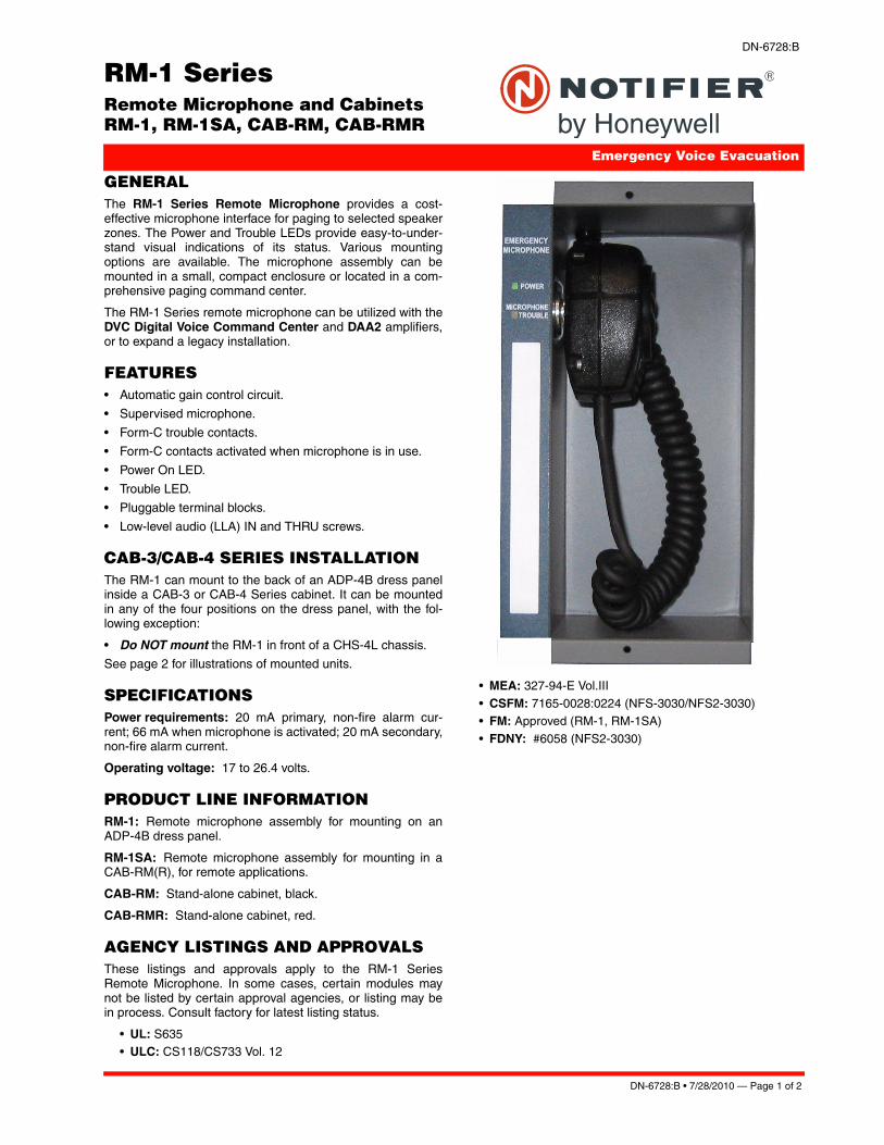
DN-6728:B • 7/28/2010 — Page 1 of 2
RM-1 SeriesRemote Microphone and Cabinets RM-1, RM-1SA, CAB-RM, CAB-RMR
Emergency Voice Evacuation
DN-6728:B
GENERALThe RM-1 Series Remote Microphone provides a cost-effective microphone interface for paging to selected speakerzones. The Power and Trouble LEDs provide easy-to-under-stand visual indications of its status. Various mountingoptions are available. The microphone assembly can bemounted in a small, compact enclosure or located in a com-prehensive paging command center.
The RM-1 Series remote microphone can be utilized with theDVC Digital Voice Command Center and DAA2 amplifiers,or to expand a legacy installation.
FEATURES • Automatic gain control circuit.
• Supervised microphone.
• Form-C trouble contacts.
• Form-C contacts activated when microphone is in use.
• Power On LED.
• Trouble LED.
• Pluggable terminal blocks.
• Low-level audio (LLA) IN and THRU screws.
CAB-3/CAB-4 SERIES INSTALLATIONThe RM-1 can mount to the back of an ADP-4B dress panelinside a CAB-3 or CAB-4 Series cabinet. It can be mountedin any of the four positions on the dress panel, with the fol-lowing exception:
• Do NOT mount the RM-1 in front of a CHS-4L chassis.
See page 2 for illustrations of mounted units.
SPECIFICATIONSPower requirements: 20 mA primary, non-fire alarm cur-rent; 66 mA when microphone is activated; 20 mA secondary,non-fire alarm current.
Operating voltage: 17 to 26.4 volts.
PRODUCT LINE INFORMATIONRM-1: Remote microphone assembly for mounting on anADP-4B dress panel.
RM-1SA: Remote microphone assembly for mounting in aCAB-RM(R), for remote applications.
CAB-RM: Stand-alone cabinet, black.
CAB-RMR: Stand-alone cabinet, red.
AGENCY LISTINGS AND APPROVALSThese listings and approvals apply to the RM-1 SeriesRemote Microphone. In some cases, certain modules maynot be listed by certain approval agencies, or listing may bein process. Consult factory for latest listing status.
• UL: S635• ULC: CS118/CS733 Vol. 12
• MEA: 327-94-E Vol.III
• CSFM: 7165-0028:0224 (NFS-3030/NFS2-3030)• FM: Approved (RM-1, RM-1SA)
• FDNY: #6058 (NFS2-3030)

Page 2 of 2 — DN-6728:B • 7/28/2010
NOTIFIER® is a registered trademark of Honeywell International Inc.
©2010 by Honeywell International Inc. All rights reserved. Unauthorized useof this document is strictly prohibited.
This document is not intended to be used for installation purposes. We try to keep our product information up-to-date and accurate.
We cannot cover all specific applications or anticipate all requirements. All specifications are subject to change without notice.
For more information, contact Notifier. Phone: (203) 484-7161, FAX: (203) 484-7118.www.notifier.com
Made in the U.S. A.
RM-1 MOUNTING & CABINET DIMENSIONS
AT RIGHT: RM-1SA (right) and in CAB-RM or CAB-RMR.
BELOW: RM-1 (left) and on ADP-4B dress panel.
CAB-RM/CAB-RMRDIMENSIONS inches (mm)
DEPTH WITHOUT DOOR
HEIGHT/WIDTH WITHOUT DOOR
6728rm1.wmf 6728
mt2
a.w
mf
6728
mt1
.wm
f
6728
rmsa
.wm
f
6728
cab.
wm
f

DN-6940:B1 • 8/31/2011 — Page 1 of 4
LCD-160Liquid Crystal Display
Annunciator Control Systems
DN-6940:B1 • D-115
GeneralThe LCD-160 is a 640-character Liquid Crystal Display (LCD)annunciator and remote control for the NOTIFIER NFS-3030/NFS2-3030 Fire Alarm Control Panel (FACP). The LCD-160will mimic the top portion (160 characters) of the NFS-3030/NFS2-3030’s 640-character display. This provides the eventand preprogrammed custom messages as displayed on themain panel. The full screen contains soft key functions, andcan display other panel information.
LCD-160 Features• 640-character Liquid Crystal Display with backlit control.
• On-board input, output, and status indicators to supportdiagnostics.
• Software upgrades and foreign-languages character setsvia serial port from a panel or other device using theRemote Data Port (RDP) interface. Upgrades do not requirethe replacement of any programmable devices.
• Rubberized keypad.• Input for AKS-1B key switch.
• Fits in two ACS annunciator module locations.• Display and Control Center (DCC) participation/indication.
RDP InterfaceAny communication between the control panel and any RDPdevice, such as the LCD-160, occurs over an RDP interface.
• RDP interface communication is supervised by the FACPand the LCD-160.
• RDP bus can drive up to 32 RDP devices. The FACP mustbe at one end of the bus; the last RDP device on the circuitmust have an enabled end-of-line resistor.
• Each LCD-160 on the bus requires a non-resettable 24VDC power connection. The power circuit is inherentlysupervised and a loss of power registers as a communica-tion failure at the control panel.
• The LCD-160 can be powered by a regulated remote powersupply listed for fire-protective signaling use. If the 24 VDCpower comes from a non-power-limited source, it mustremain separate from the power-limited RDP bus.
SpecificationsInput supply voltage (TB2): Regulated, filtered 24 VDC vianon-resettable power supply interface listed for fire-protectivesignaling use. Sources can be: panels with integrated powersupplies, main power supplies (AMPS-24, etc.), auxiliarypower supplies (APS2-6R, etc.); or a compatible accessoriesoutput. If RDP devices are to be powered by separate powersupplies, a common reference connection must be estab-lished.
Data communications port (TB1): Power-limited RDP inter-face.
Current draw: Standby current: 0.300 A with backlight on,0.075 A with backlight off. Alarm current: 0.325 A with back-light on, all LEDs active.
RDP BUS WIRING SPECIFICATIONSWiring distance: 4000 feet (1219.2 m) at 18 AWG (0.78 mm²)between the panel and the last device on the RDP bus (sub-ject to system’s power restrictions).
Wiring size: 18 to 12 AWG (0.78 to 3.1 mm²) twisted-paircable, with characteristic impedance of 120 ohms ± 20%.
Wire resistance: Limit total wire resistance to 100 ohms onthe RDP bus, and 10 ohms on the RDP device power circuit.Unloaded resistance between RDP connectors must begreater than 1K ohm. A remote power supply is required if totalpower wiring resistance exceeds 10 ohms.
NOTE: 1) DO NOT RUN CABLE adjacent to, or in the same con-duit as: 120 VAC service; “noisy” electrical circuits that are power-ing mechanical bells or horns; audio circuits above 25 Vrms; motorcontrol circuits; SCR power circuits; or non-power-limited circuits.2) Refer to LCD-160 Manual, document no. 51850, if RDP devicesare to be mounted in SEPARATE CABINETS or powered byREMOTE POWER SUPPLIES.
PHYSICAL SPECIFICATIONSTemperature/humidity range: This system meets NFPArequirements for operation at 0 – 49°C/32 – 120°F and at arelative humidity 93% ± 2% RH (noncondensing) at 32°C ±2°C (90°F ± 3°F). However, the useful life of the system'sstandby batteries and the electronic components may beadversely affected by extreme temperature ranges and humid-ity. Therefore, it is recommended that this system and itsperipherals be installed in an environment with a normal roomtemperature of 15 – 27°C/60 – 80°F.
Shipping weight: 2.50 lb. (1.134 kg)

Page 2 of 4 — DN-6940:B1 • 8/31/2011
LCD-160 Interface and Indicators The liquid crystal display is 40 characters wide and 16 linesdeep, and displays all programming screens and other infor-mation. The keypad is functional only when an entry isrequested by the system. Enter or change fields and issuecommands on the display by using the two types of keys onthe keypad: fixed function and soft keys.
Fixed function keys are the ten keys labeled on the front ofthe LCD-160, operating at all times on all screens unless oth-erwise noted. With both an active command center and DCCenabled at the panel, Acknowledge, Signal Silence, SystemReset, and Drill require permission before they can be pro-cessed.
Acknowledge: Press to respond to any event or trouble sig-nal. If enabled, silences the LCD-160 piezo sounder. Sends anacknowledge message to the panel.
Signal Silence: Press to send a system silence command tothe panel, with the particular silencing action informationstored at the FACP. Verification screen appears on networkeddisplays.
System Reset: Press to send a system reset command to thepanel, with the particular reset action information stored at theFACP. Verification screen appears on networked displays.
Drill: Press (hold for two seconds) to activate all silenceablefire output circuits.
Lamp Test: Press to test the LED indicators and the piezo, ordisplay firmware version numbers.
Fire Alarm: Scroll/display a list of associated events.
Security: Scroll/display a list of associated events.
Supervisory: Scroll/display a list of associated events.
Trouble: Scroll/display a list of associated events.
Other Event: Scroll between prealarm and disabled events.
For complete information on key functions and effects on dif-ferent panels, refer to the LCD-160 Manual and panel manu-als.
Soft keys are the six keys to the right and left of the display.Use them to select commands that appear on the display foreach different screen. Refer to the screens in the LCD-160Manual for descriptions of the applicable soft keys.
STATUS LED INDICATORSPower (green) illuminates when AC power is within normaloperating limits.
Fire Alarm (red) illuminates when at least one fire alarm eventexists. It will flash if any of these events are unacknowledged.
Pre-Alarm (red) illuminates when at least one pre-alarm eventexists. It will flash if any of these events are unacknowledged.
Security (blue) illuminates when at least one security eventexists. It will flash if any of these events are unacknowledged.
Supervisory (yellow) illuminates when at least one supervi-sory event exists. It will flash if any of these events are unac-knowledged.
System Trouble (yellow) illuminates when at least one trou-ble event exists. It will flash if any of these events are unac-knowledged.
Other Event (yellow) (future release).
6940bord.wmf
LCD-160

DN-6940:B1 • 8/31/2011 — Page 3 of 4
Signals Silenced (yellow) illuminates if notification appli-ances have been silenced. It flashes if some, but not all, of theNACs have been silenced.
Point Disabled (yellow) illuminates when at least one devicehas been disabled. It will flash until all disabled points havebeen acknowledged.
Controls Active (green) illuminates when the LCD-160assumes control of the node as a primary display.
DIAGNOSTIC LED INDICATORSStatus, LED11 (green), blinks when the LCD-160 is on. Visi-ble to the installer/troubleshooter only.
Receive, LED12 (green), blinks when data is received fromthe panel. Visible to the installer/troubleshooter only.
Transmit, LED13 (green), blinks when data is transmitted tothe panel. Visible to the installer/troubleshooter only.
Microfail, LED14 (yellow), illuminates if the microcontrollerfails. Visible to the installer/troubleshooter only.
Event Handling and the Display and Control CenterUL and ULC require that when multiple command and controlcenters are installed, only one operator at any location can bein control at any given time for functions such as acknowledge,silence, and reset. This is called the Display and Control Cen-ter (DCC). DCC operation provides a mechanism to pass net-
work control to alternate network control centers. This protocolallows for a “request for control” from another networkedpanel, which will be accepted or rejected from the currentDCC. A 15-second time-out allowance provides for an auto-matic passing of control in the event there is no response fromthe original DCC. If the NFS-3030/NFS2-3030 panel associ-ated with an LCD-160 has been programmed to participate inDCC, all remote displays with Local Control ON will automati-cally participate.
Agency Listings and ApprovalsThese listings and approvals apply to the LCD-160. In somecases, certain modules or applications may not be listed bycertain approval agencies, or listing may be in process. Con-sult factory for latest listing status.
• UL: S635 • ULC: S635 • MEA: 8-04-E (annunciator only)
• FDNY: COA#6065 (with NFS2-3030) • CSFM: 7120-0028:0227, 7165-0028:0224 • FM Approved
RDP Bus Wire Runs
Sample Screen:Point Event Display

Page 4 of 4 — DN-6940:B1 • 8/31/2011
NOTIFIER® is a registered trademark of Honeywell International Inc. ©2011 by Honeywell International Inc. All rights reserved. Unauthorized useof this document is strictly prohibited.
This document is not intended to be used for installation purposes. We try to keep our product information up-to-date and accurate.
We cannot cover all specific applications or anticipate all requirements. All specifications are subject to change without notice.
For more information, contact Notifier. Phone: (203) 484-7161, FAX: (203) 484-7118.www.notifier.com
Made in the U.S. A.
Product Line InformationLCD-160: 640-character Liquid Crystal Display annunciator.
BackboxesThe following backboxes can be surface- or semi-flush-mounted to provide an enclosure for remote mounting. Usewith 1/2" (1.27 cm) conduit in the provided knockouts.
ABS-2D (black) and ABS-2DR (red): Surface- or semi-flushenclosure for remote mounting. Mounts an LCD-160 directly tothe enclosure’s hinged dress plate. The ABS-2D and ABS-2DR do NOT support the installation of the AKS-1B key-switch. Not for use in Canadian applications. Optional trim ringTR-ABS2D for semi-flush mounting. Dimensions, box: 12.0"(30.480 cm) H x 12.0" (30.480 cm) W x 3.797" (9.644 cm) D(NOTE: The black ABS-2D is slightly deeper). Dimensions,door: 12.0" (30.480 cm) H x 12.0" (30.480 cm) W x 1.250"(3.175 cm) D.
ABS-4D (black) and ABS-4DR (red): Surface- or semi-flush-enclosure for remote mounting. Mounts an LCD-160 and twoannunciators directly to the enclosure’s hinged dress plate.The ABS-4D and ABS-4DR do NOT support the installation ofthe AKS-1B key-switch. Dimensions, box: 11.97" (30.40 cm)H x 19.87" (50.47 cm) W x 3.5" (8.89 cm) D. Dimensions,door: 11.97" (30.40 cm) H x 19.87" (50.47 cm) W x 1.250"(3.175 cm) D.
ABF-2B: Black flush enclosure for remote mounting. Mountsan LCD-160 directly to the enclosure’s dress plate. Not for usein Canadian applications. Includes a painted black metal trimplate [11" (27.94 cm) high x 10.625" (26.99 cm) wide] andadhesive-backed annunciator label. 9.938" (25.24 cm) high x9.188" (23.34 cm) wide x 3.75" (9.525 cm) deep.
ABF-2DB: Black flush enclosure for remote mounting. Mountsan LCD-160 directly to the enclosure’s dress plate. Does notsupport the installation of AKS-1B. Box dimensions: 9.938"(25.24 cm) high x 9.188" (23.24 cm) wide x 3.75" (9.525 cm)deep.Door dimensions: 11" (29.94 cm) high x 10.375" (26.35cm) wide x 0.75" (1.9 cm) deep.
ABF-4B: Black flush enclosure for remote mounting of oneLCD-160 and two annunciator modules directly to the enclo-sure’s dress plate. Knockouts are provided for use with 1/2"(1.27 cm) conduit. Includes a painted black metal trim plate[11" (27.94 cm) high x 19.375" (49.21 cm) wide] and an annun-ciator label. 9.938" (25.24 cm) high x 17.75" (45.09 cm) wide x2.5" (6.35 cm) deep.
CAB-4 Series cabinets: Surface- or semi-flush-mounted, insizes to accommodate one to four rows of equipment plus bat-teries (up to two 26 AH batteries). Four sizes are available.Doors are ordered separately, and feature reversible hinges tomount doors on the left or right side. Doors also open a full180°. Keylocks are included. For dimensions and further infor-mation, see datasheet DN-6857.
ACCESSORIESDP-DISP: Dress Panel Display for cabinet mounting of anLCD-160. LCD-160 mounts directly to the dress panel, whichhinge-mounts to the top tier of a CAB-4 Series backbox.
ADP-4B: Annunciator Dress Panel-4B (black) for cabinetmounting of an LCD-160. LCD-160 mounts directly to thedress panel, which hinge-mounts to the tier of a CAB-4 Seriesbackbox.
TR-ABS2D: Optional trim ring for semi-flush mounting ABS-2D(R).
VP-2B: Vented Dress Panel for use with the ADP-4B dresspanel installed in the top tier of a NOTIFIER cabinet. It coversthe gap between the dress panel and top of the cabinet.
AKS-1B: Annunciator Key Switch provides access security forthe control switches on the LCD-160. Key-switch kit includeskey, hardware, and an annunciator label.

FSP-851(A) SeriesIntelligent Plug-In PhotoelectricSmoke Detectors with FlashScan®
Intelligent/Addressable Devices
DN-6935:D • H-202
GeneralNotifier FSP-851(A) Series intelligent plug-in smoke detectors with integral communication provide features that surpass con-ventional detectors. Detector sensitivity can be programmed in the control panel software. Sensitivity is continuously monitored and reported to the panel. Point ID capability allows each detec-tor’s address to be set with rotary, decimal address switches, providing exact detector location for selective maintenance when chamber contamination reaches an unacceptable level. The FSP-851(A) photoelectric detector’s unique optical sensing chamber is engineered to sense smoke produced by a wide range of combustion sources. Dual electronic thermistors add 135°F (57°C) fixed-temperature thermal sensing on the FSP-851T(A). The FSP-851R(A) is a remote test capable detector for use with DNR(A)/DNRW duct detector housings. FSP-851(A) series detectors are compatible with Notifier Onyx and CLIP series Fire Alarm Control Panels (FACPs).
FlashScan® (U.S. Patent 5,539,389) is a communication proto-col developed by Notifier that greatly increases the speed of communication between analog intelligent devices. Intelligent devices communicate in a grouped fashion. If one of the devices in the group has new information, the panel’s CPU stops the group poll and concentrates on single points. The net effect is response speed greater than five times that of earlier designs.
Features• Sleek, low-profile design.• Addressable-analog communication.• Stable communication technique with noise immunity.• Low standby current.• Two-wire SLC connection.• Compatible with FlashScan® and CLIP protocol systems. • Rotary, decimal addressing (1-99 on CLIP systems, 1-159 on
FlashScan systems).• Optional remote, single-gang LED accessory.• Dual LED design provides 360° viewing angle.• Visible bi-color LEDs blink green every time the detector is
addressed, and illuminate steady red on alarm (FlashScan systems only).
• Remote test feature from the panel.• Walk test with address display (an address on 121 will blink
the detector LED: 12-[pause]-1(FlashScan systems only).• Built-in functional test switch activated by external magnet.• Built-in tamper-resistant feature.• Sealed against back pressure.• Constructed of off-white fire-resistant plastic, designed to
commercial standards, and offers an attractive appearance.• 94-5V plastic flammability rating.• SEMS screws for wiring of the separate base.• Optional relay, isolator, and sounder bases.
SpecificationsSensitivity: 0.5% to 2.35% per foot obscuration
Size: 2.1" (5.3 cm) high; base determines diameter.
– B210LP(A): 6.1" (15.5 cm) diameter.– B501(A): 4.1" (10.4 cm) diameter.– B200S(A): 6.875" (17.46 cm) diameter.
– B200SR(A): 6.875" (17.46 cm) diameter. – B224RB(A): 6.2" (15.748 cm) diameter. – B224BI(A): 6.2" (15.748 cm) diameter.
Shipping Weight: 5.2oz. (147g).
Operating Temperature range: FSP-851(A), 0°C to 49°C (32°F to 120°F). FSP-851T(A), 0°C to 38°C (32°F to 100°F). Low temperature signal for FSP-851T(A) at 45°F +/- 10°F (7.22°C +/- 5.54°C). FSP-851R(A) installed in a DNR(A)/DNRW, -20°C to 70°C (-4°F to 158°F).
UL/ULC Listed Velocity Range: 0-4000 ft/min. (1219.2 m/min.), suitable for installation in ducts.
Relative Humidity: 10%-93% noncondensing.
Thermal Ratings: Fixed-temperature setpoint 135°F (57°C).
DETECTOR SPACING AND APPLICATIONS
FSP-851(A) in B210LP(A) Base B210
-295
1.jp
g
Notifier recommends spacing detectors in compliance with NFPA 72. In low airflow applications with smooth ceiling, space detectors 30 feet (9.144m) for ceiling heights 10 feet (3.148m) and higher. For specific information regarding detector spacing, placement, and special applications refer to NFPA 72. System Smoke Detector Application Guide, document A05-1003, is available at systemsensor.com
ELECTRICAL SPECIFICATIONSVoltage Range: 15-32 volts DC peak.
Standby Current (max. avg.): 300μA @ 24VDC (one commu-nication every five seconds with LED enabled).
LED Current (max.): 6.5mA @ 24 VDC (“ON”).
InstallationFSP-851(A) plug-in detectors use a separate base to simplify installation, service, and maintenance. A special tool allows maintenance personnel to plug in and remove detectors without using a ladder.
Mount base (all base types) on an electrical backbox which is at least 1.5" (3.81 cm) deep. For a chart of compatible junction boxes, see DN-60054.
NOTE: 1) Because of inherent supervision provided by the SLC loop, end-of-line resistors are not required. Wiring “T-taps” or branches are permitted for Style 4 (Class “B”) wiring. 2) When using relay or sounder bases, consult the ISO-X(A) installation
DN-6935:D • 12/08/2011 — Page 1 of 2

-Notifier® and FlashScan® are registered trademarks of Honeywell International Inc.©2011 by Honeywell International Inc. All rights reserved. Unauthorized use of this document is strictly prohibited.
sheet I56-1380 for device limitations between isolator modules and isolator bases.
Agency Listings and ApprovalsThese listings and approvals apply to the modules specified in this document. In some cases, certain modules or applications may not be listed by certain approval agencies, or listing may be in process. Consult factory for latest listing status.
• UL Listed: S1115. • ULC Listed: S1115 (FSP-851A, FSP-851RA, FSP-851TA). • MEA Listed: 225-02-E .• FM Approved.• CSFM: 7272-0028:0206 .• Maryland State Fire Marshal: Permit # 2122 .• BSMI: CI313066760036.• CCCF: Certif. # 2004081801000017 (FSP-851T)
Certif. # 2004081801000016 (FSP-851).• U.S. Coast Guard: 161.002/42/1 (NFS-640); 161.002/50/0
(NFS2-640/NFS-320/NFS-320C, excluding B210LP(A)).• Lloyd’s Register: 11/600013 (NFS2-640/NFS-320/NFS-
320C, excluding B210LP(A)).
Product Line InformationNOTE: “A” suffix indicates ULC Listed model.
FSP-851: Low-profile intelligent photoelectric sensor. Must be mounted to one of the bases listed below.
FSP-851A: Same as FSP-851 but with ULC listing.
FSP-851T: Same as FSP-851 but includes a built-in 135°F (57°C) fixed-temperature thermal device.
FSP-851TA: Same as FSP-851T but with ULC listing.
FSP-851R: Low-profile intelligent photoelectric sensor, remote test capable. For use with DNRA/DNRW.
FSP-851RA: Same as FSP-851R but with ULC listing. For use with DNRA.
INTELLIGENT BASESNOTE: “A” suffix indicates ULC Listed model.
NOTE: For details on intelligent bases, see DN-60054.
B210LP(A): Standard U.S. flanged low-profile mounting base.
B210LPBP: Bulk pack of B210LP; package contains 10.
B501(A): Standard European flangeless mounting base.
B501BP: Bulk pack of B501; package contains 10.
B200S(A): Intelligent, programmable sounder base capable of producing sound output in high or low volume with ANSI Tempo-ral 3, ANSI Temporal 4, continuous tone, marching tone, and custom tone.
B200SR(A): Intelligent sounder base capable of producing sound output with ANSI Temporal 3 or continuous tone. Replaces B501BH series bases in retrofit applications.
B224RB(A): Plug-in System Sensor relay base. Screw termi-nals: up to 14 AWG (2.0 mm²). Relay type: Form-C. Rating: 2.0 A @ 30 VDC resistive; 0.3 A @ 110 VDC inductive; 1.0 A @ 30 VDC inductive.
B224BI(A): Plug-in System Sensor isolator detector base. Maximum 25 devices between isolator bases .
ACCESSORIESF110: Retrofit flange to convert B210LP(A) to match the B710LP(A) profile, or to convert older high-profile bases to low-profile.
F110BP: Bulk pack of F110; package contains 15.
F210: Replacement flange for B210LP(A) base.
RA100Z(A): Remote LED annunciator. 3 – 32 VDC. Mounts to a U.S. single-gang electrical box. For use with B501(A) and B210LP(A) bases only.
SMB600: Surface mounting kit
M02-04-00:Test magnet.
M02-09-00: Test magnet with telescoping handle.
XR2B: Detector removal tool. Allows installation and/or removal of detector heads from bases in high ceiling applications.
XP-4: Extension pole for XR2B. Comes in three 5-foot (1.524 m) sections.
T55-127-010: Detector removal tool without pole.
BCK-200B: Black detector covers for use with FSP-851(A) only; box of 10.
WCK-200B: White detector covers for use with FSP-851(A)only; box of 10.
Page 2 of 2 — DN-6935:D • 12/08/2011
This document is not intended to be used for installation purposes. We try to keep our product information up-to-date and accurate.
We cannot cover all specific applications or anticipate all requirements. All specifications are subject to change without notice.
For more information, contact Notifier. Phone: (203) 484-7161, FAX: (203) 484-7118.www.notifier.com
Made in the U.S. A.

DN-60429:C1 • 4/19/2012 — Page 1 of 2
DNR(A)/DNRW InnovairFlexIntelligent Non-Relay Photoelectric Duct Smoke Detector
Intelligent Devices
DN-60429:C1
GeneralThe Notifier InnovairFlex® DNR(A) intelligent non-relay photo-electric duct smoke detector and DNRW watertight non-relayphotoelectric duct smoke detector feature a pivoting housingthat fits both square and rectangular footprints capable ofmounting to a round or rectangular duct.
DNRW duct smoke detector, with its NEMA-4 rating, is listedas a watertight, UV resistant enclosure providing protectionagainst falling dirt, rain, and windblown dust, splashing andhose directed water, allowing operators to use the detector inthe most extreme environments.
These units sense smoke in the most challenging conditions,operating in airflow speeds of 100 to 4,000 feet per minute (0.5to 20.32 m/s), temperatures of -4°F to 158°F (-20°C to 70°C),and a humidity range of 0 to 95 percent (non-condensing.)
An improved cover design isolates the sensor head, whichallows for ease of maintenance. A cover tamper feature indi-cates a trouble signal for a removed or improperly installedsensor cover. The Notifier InnovairFlex housing provides a 3/4-inch conduit knockout and ample space to facilitate easy wir-ing and mounting of a relay module.
The Notifier InnovairFlex duct smoke detector can be custom-ized to meet local codes and specifications without additionalwiring. The new InnovairFlex product line is compatible with allprevious Innovair models, including remote test accessories.
Features• Photoelectric, integrated low-flow technology.• Air velocity rating from 100 ft/min to 4,000 ft/min (0.5 m/s to
20.32 m/s).• Versatile mounting options: square or rectangular configu-
ration.• Broad ranges for operating temperature (-4°F to 158°F, -
20°C to 70°C) and humidity (0% to 95% non-condensing).• Patented sampling tube installs from front or back of the
detector with no tools required.• Cover tamper signal.
• Increased wiring space with a newly added 3/4” conduitknockout.
• Available space within housing to accommodate mountingof a relay module.
• Easily accessible code wheels on sensor head (sold sepa-rately).
• Clear cover for convenient visual inspection.• Remote testing capability.• Requires com line power only.
• Accommodates the installation of an addressable relaymodule, sold separately, (FRM-1 or NC-100R) for applica-tions requiring a Form-C relay.
SpecificationsSize: (Rectangle) 14.38 in (37 cm) Length; 5 in (12.7 cm)Width, 2.5 in (6.6 cm) Depth.
Size: (Square) 7.75 in (19.7 cm) Length; 9 in (22.9 cm) Width;2.5 in (6.35 cm) Depth.
Weight: 1.6 lb (0.73 kg).
Operating Temperature Range: -4°F to 158°F (-20°C to70°C).
Storage Temperature Range: -22°F to 158°F (-30°C to70°C).
Operating Humidity Range: 0% to 95% relative humidity(non-condensing).
Air Duct Velocity: 100 to 4,000 ft/min (0.5 to 20.32 m/s).
AccessoriesNotifier provides system flexibility with a variety of accessories,including two remote test stations and different means of visi-ble and audible system annunciation. As with our duct smokedetectors, all duct smoke detectors accessories are UL listed.
DNR(W)s with a date code of 0013 or higher do not requireexternal 24VDC for remote test applications when used with aremote-test-capable detector.
ACCESSORY CURRENT LOADS AT 24 VDC
Agency Listings and Approvals Consult product manual for lists of compatible UL-Listeddevices. In some cases, certain modules may not be listed bycertain approval agencies, or listing may be in process. Con-sult factory for latest listing status.
• UL: S911, S3705.• ULC: S635.
Device Standby Alarm
RA100Z 0mA 12 mA Max
RTS151/RTS151KEY 0mA 12mA Max
intelligent innovair-

Page 2 of 2 — DN-60429:C1 • 4/19/2012
Notifier® and FlashScan® are a registered trademark of HoneywellInternational Inc. ©2012 by Honeywell International Inc. All rights reserved. Unauthorized useof this document is strictly prohibited.
This document is not intended to be used for installation purposes. We try to keep our product information up-to-date and accurate.
We cannot cover all specific applications or anticipate all requirements. All specifications are subject to change without notice.
For more information, contact Notifier. Phone: (203) 484-7161, FAX: (203) 484-7118.www.notifier.com
Made in the U.S. A.
• CSFM: 3242-1653:0209.
• FM approved.
Product Line InformationNOTE: “A suffix indicates ULC listed model.
DNR(A): Intelligent non-relay photoelectric low flow smokedetector housing. Requires photoelectric smoke detector (soldseparately).
DNRW: Watertight intelligent non-relay photoelectric low flowduct smoke detector housing. Requires photoelectric smokedetector (sold separately).
FSP-851R(A): Remote test capable addressable low-profilephotoelectric smoke detector.
FSP-851(A): Addressable low-profile photoelectric smokedetector.
NP-100: Addressable low-profile photoelectric smoke detectorfor FireWarden series panels.
NP-100R(A): Remote test capable addressable low-profilephotoelectric smoke detector for FireWarden series panels.
DCOIL: Remote test coil. Required for older DNR(W) ductdetector housing.
DST1(A): Metal sampling tube duct width up to 1 ft (0.3m).
DST1.5(A): Metal sampling tube duct widths up to 1 ft to 2 ft(0.3 to 0.6 m).
DST3(A): Metal sampling tube duct widths up to 2 ft to 4 ft (0.6to 1.2 m).
DST5(A): Metal sampling tube duct widths up to 4 ft to 8 ft (1.2to 2.4 m).
DST10(A): Metal sampling tube duct widths up to 8 ft to 12 ft(2.4 to 3.7 m).
DH400OE-1: Weatherproof enclosure.
ETX: Metal exhaust tube duct, width 1 ft (0.3 m).
M02-04-00: Test magnet.
P48-21-00: End cap for metal sampling tubes.
RA100Z(A): Remote annunciator alarm LED.
RTS151(A): Remote test station.
RTS151KEY(A): Remote test station with key lock.
Important Note• DNRW duct detector housings with a date code of 0013 or
higher do not require a DCOIL or auxiliary 24 VDC forremote test applications when used with a remote testcapable detector.
• DNRW duct detector housings with a date code of 0012 orearlier require a DCOIL and auxiliary 24 VDC power forremote test applications.
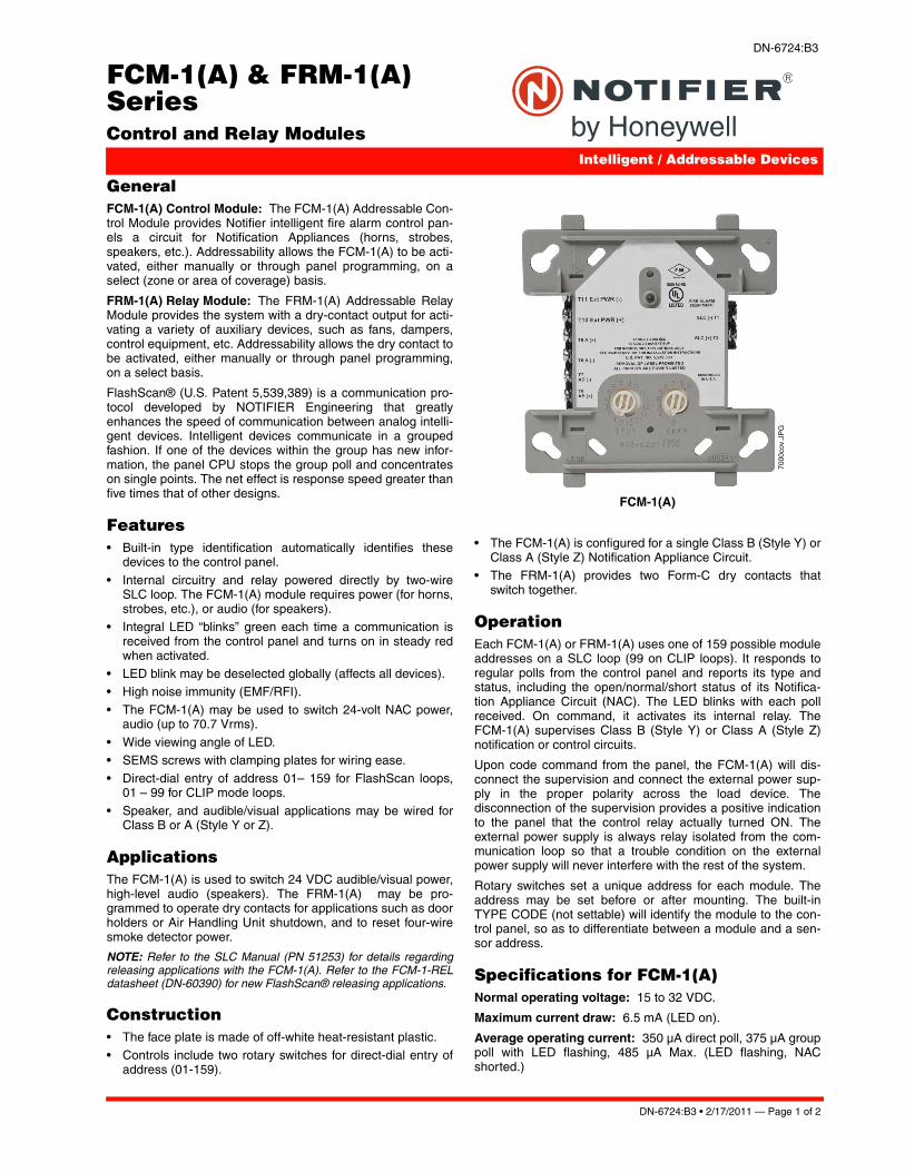
DN-6724:B3 • 2/17/2011 — Page 1 of 2
FCM-1(A) & FRM-1(A) SeriesControl and Relay Modules
Intelligent / Addressable Devices
DN-6724:B3
GeneralFCM-1(A) Control Module: The FCM-1(A) Addressable Con-trol Module provides Notifier intelligent fire alarm control pan-els a circuit for Notification Appliances (horns, strobes,speakers, etc.). Addressability allows the FCM-1(A) to be acti-vated, either manually or through panel programming, on aselect (zone or area of coverage) basis.
FRM-1(A) Relay Module: The FRM-1(A) Addressable RelayModule provides the system with a dry-contact output for acti-vating a variety of auxiliary devices, such as fans, dampers,control equipment, etc. Addressability allows the dry contact tobe activated, either manually or through panel programming,on a select basis.
FlashScan® (U.S. Patent 5,539,389) is a communication pro-tocol developed by NOTIFIER Engineering that greatlyenhances the speed of communication between analog intelli-gent devices. Intelligent devices communicate in a groupedfashion. If one of the devices within the group has new infor-mation, the panel CPU stops the group poll and concentrateson single points. The net effect is response speed greater thanfive times that of other designs.
Features• Built-in type identification automatically identifies these
devices to the control panel.
• Internal circuitry and relay powered directly by two-wireSLC loop. The FCM-1(A) module requires power (for horns,strobes, etc.), or audio (for speakers).
• Integral LED “blinks” green each time a communication isreceived from the control panel and turns on in steady redwhen activated.
• LED blink may be deselected globally (affects all devices).• High noise immunity (EMF/RFI).
• The FCM-1(A) may be used to switch 24-volt NAC power,audio (up to 70.7 Vrms).
• Wide viewing angle of LED.• SEMS screws with clamping plates for wiring ease.
• Direct-dial entry of address 01– 159 for FlashScan loops,01 – 99 for CLIP mode loops.
• Speaker, and audible/visual applications may be wired forClass B or A (Style Y or Z).
ApplicationsThe FCM-1(A) is used to switch 24 VDC audible/visual power,high-level audio (speakers). The FRM-1(A) may be pro-grammed to operate dry contacts for applications such as doorholders or Air Handling Unit shutdown, and to reset four-wiresmoke detector power.
NOTE: Refer to the SLC Manual (PN 51253) for details regardingreleasing applications with the FCM-1(A). Refer to the FCM-1-RELdatasheet (DN-60390) for new FlashScan® releasing applications.
Construction• The face plate is made of off-white heat-resistant plastic.• Controls include two rotary switches for direct-dial entry of
address (01-159).
• The FCM-1(A) is configured for a single Class B (Style Y) orClass A (Style Z) Notification Appliance Circuit.
• The FRM-1(A) provides two Form-C dry contacts thatswitch together.
OperationEach FCM-1(A) or FRM-1(A) uses one of 159 possible moduleaddresses on a SLC loop (99 on CLIP loops). It responds toregular polls from the control panel and reports its type andstatus, including the open/normal/short status of its Notifica-tion Appliance Circuit (NAC). The LED blinks with each pollreceived. On command, it activates its internal relay. TheFCM-1(A) supervises Class B (Style Y) or Class A (Style Z)notification or control circuits.
Upon code command from the panel, the FCM-1(A) will dis-connect the supervision and connect the external power sup-ply in the proper polarity across the load device. Thedisconnection of the supervision provides a positive indicationto the panel that the control relay actually turned ON. Theexternal power supply is always relay isolated from the com-munication loop so that a trouble condition on the externalpower supply will never interfere with the rest of the system.
Rotary switches set a unique address for each module. Theaddress may be set before or after mounting. The built-inTYPE CODE (not settable) will identify the module to the con-trol panel, so as to differentiate between a module and a sen-sor address.
Specifications for FCM-1(A)Normal operating voltage: 15 to 32 VDC.
Maximum current draw: 6.5 mA (LED on).
Average operating current: 350 μA direct poll, 375 μA grouppoll with LED flashing, 485 μA Max. (LED flashing, NACshorted.)
FCM-1(A)
7000
cov.
JPG

Page 2 of 2 — DN-6724:B3 • 2/17/2011
Notifier® and FlashScan® are registered trademarks of HoneywellInternational Inc. ©2011 by Honeywell International Inc. All rights reserved. Unauthorized useof this document is strictly prohibited.
This document is not intended to be used for installation purposes. We try to keep our product information up-to-date and accurate.
We cannot cover all specific applications or anticipate all requirements. All specifications are subject to change without notice.
For more information, contact Notifier. Phone: (203) 484-7161, FAX: (203) 484-7118.www.notifier.com
Made in the U.S. A.
Maximum NAC Line Loss: 4 VDC.
External supply voltage (between Terminals T10 and T11): Maximum (NAC): Regulated 24 VDC; Maximum(Speakers): 70.7 V RMS, 50W.
Drain on external supply: 1.7 mA maximum using 24 VDCsupply; 2.2 mA Maximum using 80 VRMS supply.
Max NAC Current Ratings: For class B wiring system, thecurrent rating is 3A; For class A wiring system, the current rat-ing is 2A.
Temperature range: 32°F to 120°F (0°C to 49°C).
Humidity range: 10% to 93% non-condensing.
Dimensions: 4.5" (114.3 mm) high x 4" (101.6 mm) wide x1.25" (31.75 mm) deep. Mounts to a 4" (101.6 mm) square x2.125" (53.975 mm) deep box.
Accessories: SMB500 Electrical Box; CB500 Barrier
Specifications for FRM-1(A)Normal operating voltage: 15 to 32 VDC.
Maximum current draw: 6.5 mA (LED on).
Average operating current: 230 μA direct poll; 255 μA grouppoll.
EOL resistance: not used.
Temperature range: 32°F to 120°F (0°C to 49°C).
Humidity range: 10% to 93% non-condensing.
Dimensions: 4.5" (114.3 mm) high x 4" (101.6 mm) wide x1.25" (31.75 mm) deep. Mounts to a 4" (101.6 mm) square x2.125" (53.975 mm) deep box.
Accessories: SMB500 Electrical Box; CB500 Barrier
Agency Listings and ApprovalsIn some cases, certain modules may not be listed by certainapproval agencies, or listing may be in process. Consult fac-tory for latest listing status.
• UL: S635• ULC: S3705 (A version only) • FM Approved• CSFM: 7300-0028:0219 • MEA: 14-00-E
• FDNY: COA #6067, #6065
Contact Ratings for FRM-1(A)
NOTE: Maximum (Speakers): 70.7 V RMS, 50 W
Product Line InformationNOTE: “A” suffix indicates ULC Listed model.
FCM-1(A): Intelligent Addressable Control Module.
FRM-1(A): Intelligent Addressable Relay Module.
A2143-20: Capacitor, required for Class A (Style Z) operationof speakers.
SMB500: Optional Surface-Mount Backbox.
CB500: Control Module Barrier — required by UL for separat-ing power-limited and non-power limited wiring in the samejunction box as FCM-1(A).
NOTE: For installation instructions, see the following documents:
• FCM-1(A) Installation document I56-1169.
• FRM-1(A) Installation document I56-3502.
• Notifier SLC Wiring Manual, document 51253.
Current Rating
Maximum Voltage
Load Description Application
3 A 30 VDC Resistive Non-Coded
2 A 30 VDC Resistive Coded
.9 A 110 VDC Resistive Non-Coded
.9 A 125 VDC Resistive Non-Coded
.5 A 30 VDC Inductive(L/R=5ms) Coded
1 A 30 VDC Inductive(L/R=2ms) Coded
.3 A 125 VAC Inductive(PF=0.35) Non-Coded
1.5 A 25 VACInductive(PF=0.35) Non-Coded
.7 A 70.7 VACInductive(PF=0.35) Non-Coded
2 A 25 VACInductive(PF=0.35) Non-Coded

dn-6927:a • 04/30/09 — Page 1 of 2
FCPS-24S6(C/E) & FCPS-24S8(C/E)6- & 8-Amp 24-VoltRemote Power Supplies
Power Supplies
dn-6927:a
GeneralThe FCPS-24S6E (6-amp) and FCPS-24S8E (8-amp) areremote power supplies with battery charger. The FCPS-24S6/-24S8 may be connected to any 12 or 24 volt fire alarm controlpanel (FACP) or may be used as stand-alone supplies. Pri-mary applications include notification appliance (bell) circuit(NAC) expansion (to support ADA requirements and NAC syn-chronization) or auxiliary power to support 24 volt systemaccessories. The FCPS-24S6/-24S8 provides regulated andfiltered 24 VDC power to four notification appliance circuitsconfigured as either four Class B (Style Y) or Class A (Style Z,with ZNAC-4 option module). Alternately, the four outputs maybe configured as all non-resettable, all resettable or two non-resettable and two resettable. The FCPS-24S6/-24S8 alsocontains a battery charger capable of charging up to 18 AHbatteries. FCPS-24S6C & FCPS-24S8C are ULC-listed.
NOTE: Unless otherwise specified, the terms FCPS-24S6 andFCPS-24S8 used in this document refers to the standard FCPS-24S6 and FCPS-24S8, FCPS-24S6C and FCPS-24S8C, theFCPS-24S6E and FCPS-24S8E
Features• UL-Listed NAC synchronization using System Sensor,
Wheelock, or Gentex “Commander2” appliances.
• Operates as a “sync-follower” or as a “sync-generator”(default). See note on page 2.
• Contains two fully-isolated input/control circuits - triggeredfrom FACP NAC (NAC expander mode) or jumped perma-nently “ON” (stand-alone mode).
• Four Class B (Style Y) or four Class A (Style Z, withZNAC-4 module) NACs.
• 6-amp (FCPS-24S6) or 8-amp (FCPS-24S8) full load out-put, with 3 amps maximum/circuit, in NAC expander mode(UL 864).
• 4-amp (FCPS-24S6) or 6-amp (FCPS-24S8) continuousoutput in stand-alone mode (UL 1481).
• Compatible with coded inputs; signals passed through.
• Optional power-supervision relay (EOLR-1).• In stand-alone mode, output power circuits may be config-
ured as: resettable, (reset line from FACP required),non-resettable, or a mix of two and two.
• Fully regulated and filtered power output - optimal for pow-ering four-wire smoke detectors, annunciators, and othersystem peripherals requiring regulated/filtered power.
• Power-limiting technology meets UL power-limiting require-ments.
• Form-C normally-closed trouble relay.
• Fully supervised power supply, battery, and NACs.• Selectable earth fault detection.• AC trouble report selectable for immediate 2-hour delay.
• Works with virtually any UL 864 fire alarm control which uti-lizes an industry-standard reverse-polarity notification cir-cuit (including unfiltered and unregulated bell power).
• Requires input trigger voltage of 9 - 32 VDC.
• Self-contained in compact, locking cabinet - 15”H x 14.5”Wx 2.75”D (cm: 38.1H x 36.83W x 6.985D).
• Includes integral battery charger capable of charging up to18 AH batteries. Cabinet capable of housing 7.0 AH batter-ies.
• Battery charger may be disabled via DIP switch for applica-tions requiring larger batteries.
• Fixed, clamp-type terminal blocks accommodate up to 12AWG (3.1mm2) wire.
SpecificationsPrimary (AC) Power:
• FCPS-24S6C/-24S8C: 120 VAC, 60 Hz, 3.2A maximum.• FCPS-24S6E/-24S8E: 240 VAC, 50 Hz, 1.6A maximum.
• Wire Size: minimum #14 AWG (2.0mm2) with 600 V insula-tion.
Control Input Circuit:
• Trigger Input Voltage: 9 to 32 VDC.• Trigger Current: 2.0 mA (16 - 32 V); Per Input: 1.0 mA (9
- 16 V).Trouble Contact Rating: 5 A at 24 VDC.
Auxiliary Power Output: Specific application power 500 mAmaximum.
Output Circuits:
• +24 VDC filtered, regulated.• 3.0 A maximum for any one circuit.
• Total continuous current for all outputs (stand-alone mode):– FCPS-24S6: 4.0 A maximum.– FCPS-24S8: 6.0 A maximum.
• Total short-term current for all outputs (NAC expander mode):– FCPS-24S6: 6.0 A maximum.– FCPS-24S8: 8.0 A maximum.
Secondary Power (Battery) Charging Circuit:
• Supports lead-acid batteries only.• Float-charge voltage: 27.6 VDC.
6927pho1.jpg

Page 2 of 2 — dn-6927:a • 04/30/09
System Sensor® and NOTIFIER® are registered trademarks of HoneywellInternational Inc. ©2009 by Honeywell International Inc. All rights reserved. Unauthorized useof this document is strictly prohibited.
This document is not intended to be used for installation purposes. We try to keep our product information up-to-date and accurate.
We cannot cover all specific applications or anticipate all requirements. All specifications are subject to change without notice.
For more information, contact Notifier. Phone: (203) 484-7161, FAX: (203) 484-7118.www.notifier.com
Made in the U.S. A.
• Maximum current charge: 1.5 A.
• Maximum battery capacity: 18 AH.
ApplicationsExample 1: Expand notification appliance power an additional6.0 A (FCPS-24S6) or 8.0 A (FCPS-24S8). Use up to fourClass B (Style Y) outputs or four Class A (Style Z) outputs(using ZNAC-4). For example, the FACP notification appliancecircuits will activate the FCPS when reverse-polarity activationoccurs. Trouble conditions on the FCPS are sensed by theFACP through the notification appliance circuit.
Example 2: Use the FCPS to expand auxiliary regulated 24-volt system power up to 4.0 A (FCPS-24S6) or up to 6.0 A(FCPS-24S8). Both resettable and non-resettable poweroptions are available. Resettable outputs are created by con-necting the resettable output from the FACP to one or both ofthe FCPS inputs.
Example 3: Use addressable control modules to activate theFCPS instead of activating it through the FACP notificationappliance circuits. This typically allows for mounting the FCPSat greater distances* away from the FACP while expandingsystem architecture in various applications.
For example, an addressable control module is used to acti-vate the FCPS, and an addressable monitor module is used tosense FCPS trouble conditions. Local auxiliary power outputfrom the FCPS provides power to the addressable controlmodule.
*NOTE: Addressable FACPs are capable of locating control andmonitor modules at distances of up to 12,500 feet (3,810 meters).
Sync Follower/Generator NoteIn some installations, it is necessary to synchronize the flashtiming of all strobes in the system for ADA compliance.Strobes accomplish this by monitoring very short timing pulseson the NAC power which are created by the FACP. Wheninstalled at the end of a NAC wire run, the FCPS-24S6/-24S8can track (i.e. “follow”) the strobe synchronization timingpulses on the existing NAC wire run. This maintains the overallsystem flash timing of the additional strobes attaches to theFCPS.
When the FCPS-24S6/-24S8 is configured (via DIP switch set-tings) as a “sync follower,” the FCPS’s NAC outputs track thestrobe synchronization pulses present at the FCPS’s syncinput terminal. The pulses originate from an upstream FACP orother power supply.
When the FCPS-24S6/-24S8 are configured (via DIP switchsettings) as a “sync generator,” the FCPS’s sync input termi-nals are not used. Rather, the FCPS is the originator of thestrobe synchronization pulses on the FCPS’s NAC outputs. In“sync generator” mode, the sync type (System Sensor, Whee-lock, or Gentex) is selectable via DIP switch settings.
Standards and CodesThe FCPS-24S6 and FCPS-24S8 comply with the followingstandards:
• NFPA 72 National Fire Alarm Code.• UL 864 Standard for Control Units for Fire Alarm Systems
(NAC expander mode).• UL 1481 Power Supplies for Fire Alarm Systems.
Agency Listings and ApprovalsThese listings and approvals apply to the modules specified inthis document. In some cases, certain modules or applicationsmay not be listed by certain approval agencies, or listing maybe in process. Consult factory for latest listing status.
• UL Listed: S635, S674
• ULC Listed: S635 (FCPS-24S6C & FCPS-24S8C)• CSFM Approved: 7315-0028:225 • MEA: 299-02-E
• FM Approved
Ordering InformationFCPS-24S6: 6.0 A, 120 VAC remote charger power supply.Includes main printed circuit board, transformers, enclosure(15”H x 14.5”W x 2.75”D [cm: 38.1H x 36.83W x 6.985D]), andinstallation instructions.
FCPS-24S6C: Same as above, ULC-listed.
FCPS-24S6R: Same as FCPS-24S6 with red enclosure.
FCPS-24S6E: 6.0 A, 240 VAC remote charger power supply.Includes main printed circuit board, transformers, enclosure(15”H x 14.5”W x 2.75”D [cm: 38.1H x 36.83W x 6.985D]), andinstallation instructions.
FCPS-24S8: 8.0 A, 120 VAC remote charger power supply.Includes main printed circuit board, transformers, enclosure(15”H x 14.5”W x 2.75”D [cm: 38.1H x 36.83W x 6.985D]), andinstallation instructions.
FCPS-24S8C Same as above, ULC-listed.
FCPS-24S8R: Same as FCPS-24S8 with red enclosure.
FCPS-24S8E: 8.0 A, 240 VAC remote charger power supply.Includes main printed circuit board, transformers, enclosure(15”H x 14.5”W x 2.75”D [cm: 38.1H x 36.83W x 6.985D]), andinstallation instructions.
ZNAC-4: Class A (Style Y) NAC option module.
EOLR-1: 12/24 VDC end-of-line relay for monitoring four-wiresmoke detector power.
BAT-1270: Battery, 12-volt, 7.0 AH (two required, see BATSeries data sheet DN-6933).
PS-1270: Battery, 12-volt, 7.0 AH (two required, see PSSeries data sheet DN-1109)

DescriptionThe Wheelock ExcederTM Series expands to include the industry’s first LED notification appliances in one of the smallest, most compact single gang designs in the world. The LED patented technology by Eaton provides the industry’s lowest current draw. Ideal for Green Buildings, it’s the pinnacle of life safety, performance and energy-efficiency.
As the first notification appliances in the industry to utilize Light Emitting Diode (LED) as the light source, this breakthrough and patented optical design, resulting in best-in-class efficiency, enables material and system cost savings, allowing for a greater number of appliances on the notification appliance circuit and fewer power supplies. All strobe models feature a wide-range of candela settings (15, 30, 75, 110cd) on a single appliance. Models with an audible feature 2 sound settings (90 & 95 dB). All switches to change settings, can be set without the use of a tool and are located behind the appliance to prevent tampering.
Wheelock ExcederTM LED strobes, horn strobes and horns feature the industry’s smallest footprint and a sleek modern design that will please building owners with reduced total cost of ownership. Installers will benefit from its comprehensive feature list, including lowest current draw, single-gang design, no tools needed for setting changes, and three convenient mounting options for both new and retrofit construction. These products are suitable for indoor wall-mount applications. The LST Strobe, LHS Horn Strobe, and the LHN Horn are for 24V operation. LHN is suitable for 12V applications.
The ExcederTM LED notification appliances are listed under UL Standards 1971 and 464 and under CAN/ULC-S525 and CAN/ULC-S526.
Exceder LED Strobes and Horn Strobes may be synchronized when used in conjunction with the Wheelock DSM Sync Modules, Wheelock Power Supplies, SAFEPATH family of products or other manufacturers panels incorporating the Wheelock Patented Sync Protocol. Wheelock synchronized strobes offer an easy way to comply with ADA recommendations concerning photosensitive epilepsy.
Exceder LED Horn Strobes, Strobes & Horns
Technical Data TD450050ENEffective November 2016 Supersedes May 2014

2
Technical Data TD450050ENEffective November 2016
Exceder LED Horn Strobes, Strobes & Horns
EATON www.eaton.com
Features • Energy Efficient
• Patented LED technology provides industry’s lowest current draw
• Fewer power supplies required, smaller wire gage, reduced wire runs
• Low-Profile Design• One of the smallest, most compact single-gang designs
• Sleek, modern aesthetics with no visible mounting screws
• Special Lettering Available• 4 Field Selectable Settings in 1 Device
• Select 15, 30, 75, 110 cd
• 2 Audible Settings• Select 90 or 95 dB
• Select temporal or steady horn output
• Easy-to-Install• Finger slide switches--No tools needed for
setting changes
• IN/OUT screw terminals using #12 to #18 AWG wires
• Mounting Options include Exceder LSBB, any single-gang back-box and to 4” square with adapter kit
• Strobe Synchronization Components• Meet synchronizing standards with Wheelock’s DSM Sync
Modules, PS Power Supplies or SAFEPATH products
• Compliance• UL 1971, UL 464, ULC-S525, ULC-S526
• Factory Mutual (FM)
• California State Fire Marshal (CSFM)
• FCC Part 15, ICES
Note:N Please read these specifications and associated installation instruc-tions, before using, specifying, or installing this product. Visit Eaton.com/massnotification for current installation instructions.
General Notes• Strobes are designed to flash at 1 flash per second minimum over
their “Regulated Voltage Range.” Note that NFPA-72 specifies a flash rate of 1 to 2 flashes per second and ADA Guidelines specify a flash rate of 1 to 3 flashes per second.
• All candela ratings represent minimum effective Strobe intensity based on UL 1971.
Drawings
Figurt 1. Wall SorNbt
Figurt 2. Wall HNrn SorNbt

3
Technical Data TD450050ENEffective November 2016
Exceder LED Horn Strobes, Strobes & Horns
EATON www.eaton.com
Tablt 3. CNdt 3 HNrn SorNbt Raoings
UL/ULC Max Current a at Anechoic 95 dBA UL/ULC Max Current a at Anechoic 90 dBA
Model Voltage b 15 30 75 110 Voltageb 15 30 75 110
LHS 16.0 -33.0 0.040 0.046 0.125 0.219 16.0 -33.0 0.038 0.042 0.122 0.209
Tablt 4. SptcificaoiNn & Ordtring InfNrmaoiNn
Model Order Code Strobe Candela Red White LetteringSync w/ DSM or Wheelock Power Supplies
Horn StrobesLHSRLHSW LHSR-A LHSR-N LHSW-ALHSW-ALLHSW-N
0526 0527 0740 0741 074207430744
15/30/75/110 15/30/75/110 15/30/75/110 15/30/75/110 15/30/75/110 15/30/75/11015/30/75/110
X X X
X X XX
FIREFIRE AGENT No Lettering AGENTALERTNo Lettering
XXXXXXX
StrobesLSTRLSTW LSTR-A LSTR-AL LSTW-ALSTW-ALLSTW-NLSTR-N
0528 0529 0747 0748 0749075007510754
15/30/75/11015/30/75/11015/30/75/11015/30/75/11015/30/75/11015/30/75/11015/30/75/11015/30/75/110
X X X
X
X X XX
FIREFIRE AGENT ALERT AGENTALERT No LetteringNo Lettering
XXXXXXXX
Horns
LHNRLHNW
05300531
X X
XX
Accessories
LSBB-RLSBB-WESB-KIT-RESB-KIT-W
2420240305330534
Exceder LED BackboxExceder LED BackboxExceder LED Trim Plate Exceder LED Trim Plate
X
XX
X
Tablt 5. SptcificaoiNns
PhysicalMaterial Red or white textured UV stabilized, colored impregnated engineered plastic. Exceeds 94V-0 UL flammability rating Weight .035 lbs.Lens Light Emitting Diode (LED) in a rugged Lexan lensDimensions 4.53”H x 2.76 W x 1.27” D; Trimplate: 5.25” H x 4.58W x 0.32 DOperating Temperature Indoor: 33.8°F to 120.2°F (0°C to 49°C) and maximum humidity of 93%
Mounting & Wire ConnectionsMounting (indoor only) Wall-mount applications only. Single-gang, Exceder LSBB backboxes or to 4” square with adapter kitWire Connections #12 through #18 AWG
Power & GeneralOperating voltage 12 VDC: 8 - 17.5 VDC; 24 VDC: 16 - 33 VDC (12 VDC LHN models only)Strobe Output Rating UL 1971, ULC S526: Selectable 15, 30, 75, 110 candela outputStrobe Flash Rate Strobes are designed to flash at 1 flash per secondSynchronization Models Strobes can be synchronized with Wheelock’s DSM Sync Modules, PS-6/8 Power Supplies or SAFEPATH products,
using Wheelock patented sync protocolTemporal Audible Pattern Selectable Continuous or Code 3 Horn tone: The Code 3 temporal pattern (1/2 second on, 1/2 second off, 1/2 second on,
1/2 second off, 1/2 second on, 1-1/2 off and repeat) is specified by ANSI and NFPA 72 for standard emergency evacua-tion signaling.
a RMS current ratings are per UL maximum RMS method. UL max current rating is the maximum RMS current within the listed voltage range (16-33v for 24v units). For strobes the UL max current is usually at the minimum listed voltage (16v for 24v units). For audibles the max current is usually at the maximum listed voltage (33v for 24v units). For unfiltered FWR ratings, see installation instructions.
b Regulated Voltage Range - VDC
Exceder LED Horns
ModelRegulated Voltage Range VDC 95 dB 90 dB
LHNLHN
8.0 - 17.516.0 - 33.0
0.0240.030
0.0180.022
Tablt 2. HNrn Raoings
Exceder LED Strobes
UL/ULC Max Current a
24VDC
ModelRegulated Voltage Range VDC 15 30 75 110
LST 16.0-33.0 0.030 0.040 0.115 0.200
Tablt 1. SorNbt Raoings

Eaton is a registered trademark.
All other trademarks are property of their respective owners.
Exceder LED Horn Strobes, Strobes & Horns
Eaton1000 Eaton BoulevardCleveland, OH 44122United StatesEaton.com
Life safety & mass notification solutions273 Branchport Ave.Long Branch, NJ 07740Eaton.com/massnotification
© 2016 EatonAll Rights ReservedPrinted in USAPublication No. TD450050ENNovember 2016
Technical Data TD450050ENEffective November 2016
Architects and Engineers SpecificationsThe LED notification appliances shall be Wheelock® Exceder™ Series LHS Audible Strobe appliances, Series LST Visual Strobe appli-ances and Series LHN Audible appliances for wall-mount applica-tions with a low-profile design or approved equals. The Series LHS and LST Strobes shall be listed for UL Standard 1971 (Emergency Devices for the Hearing-Impaired) for Indoor Fire Protection Service. The Series LHS and LHN Audibles shall be UL Listed under Standard 464 (Fire Protective Signaling). All Series shall meet the require-ments of FCC Part 15. All inputs shall be compatible with standard reverse polarity supervision of circuit wiring by a Fire Alarm Control Panel (FACP) with the ability to operate from 16 to 33 VDC.
The Series LHS Audible Strobe and LST Strobe appliances shall produce a flash rate of one (1) flash per second over the Regulated Voltage Range and shall incorporate a Light Emitting Diode (LED) as the light source with a rugged Lexan® lens. The Series shall be of low current design. Where Multi-Candela appliances are specified, the strobe intensity shall have 4 field selectable settings at 15, 30, 75, 110, candela for wall mount applications. The selector switch for selecting the candela shall be tamper resistant. Appliances with candela settings shall show the candela selection in a visible location at all times when installed.
The audible shall have a minimum of two (2) field selectable settings for dBA levels and shall have a choice of continuous or temporal (Code 3) audible outputs.
The Series LHS Audible Strobe, LST Strobe and Series LHN Audible mounting options shall include LED backboxes, single-gang backbox
and to 4” square with adapter kit. Two wire appliance wiring shall be capable of directly connecting to the mounting base. Continuity checking of the entire NAC circuit prior to attaching any notification appliances shall be allowed. Removal of an appliance shall result in a supervision fault condition by the Fire Alarm Control Panel (FACP). All notification appliances shall be backwards compatible.
The Series LHS, LHN and LST wall models shall have a low profile measuring 4.53”H x 2.76”W x 1.27”D.
When synchronization is required, the appliance shall be compat-ible with Wheelock®’s DSM Sync Modules, PS Power Supplies, SAFEPATH products or other manufacturer’s panels with built-in Wheelock® Patented Sync Protocol. The strobes shall not drift out of synchronization at any time during operation. If the sync protocol fails to operate, the strobe shall revert to a non-synchronized flash-rate and still maintain (1) flash per second over its Regulated Voltage Range. The appliance shall also be designed so that the audible sig-nal may be silenced while maintaining strobe activation when used with Wheelock® patented sync protocol..
UL 1971, UL 464 ULC-S525, ULC-S526, CSFM, FM, FCC, ICES
Note:N Due to continuous development of our products, specifications and offerings are subject to change without notice in accordance with Cooper Wheelock Inc., dba Eaton standard terms and conditions.
WE ENCOURAGE AND SUPPORT NICET CERTIFICATION 3 YEAR WARRANTY

DescriptionEaton has designed its Wheelock ExcederTM LED Speaker Strobes and Speakers for high fidelity sound output for indoor ceiling-mount applications. With the widest frequency response range (300 to 8000 Hz) in the industry, the Series LSPKC and LSPSTC feature leading intelligibility with crisp, clear voice messages and tone signaling, ideal for emergency communications, mass notification, voice evacuation and fire alarm.
The Wheelock Exceder LED strobe models are the first notification appliances in the industry that utilize Light Emitting Diode (LED) as the light source—a breakthrough optical design, resulting in best-in-class efficiency that enables material and system cost savings, allowing for a greater number of appliances on the notification appliance circuit and fewer power supplies. Speaker strobe models feature a wide range of candela settings (15, 30, 75, 95 cd) on a single appliance. All switches to change settings can be set without the use of a tool and are located behind the appliance to prevent tampering.
Providing a sleek aesthetic appearance in a small, compact ceiling design, the Exceder LED High Fidelity Speakers and Speaker Strobes feature dual voltage (25/70 VRMS) capability and field selectable taps from 1/8 to 2 watts. The low profile design incorporates a speaker mounting plate for faster and easier installation. Each model has a built-in level adjustment feature and a snap-on grille cover. All inputs employ IN/OUT wiring terminals for fast installation using #12 to #18 AWG wiring.
Exceder LED speaker strobes may be synchronized when used in conjunction with the Wheelock DSM Sync Modules, Wheelock Power Supplies, SAFEPATH family of products or other manufacturers panels incorporating the Wheelock Patented Sync Protocol. Wheelock synchronized strobes offer an easy way to comply with ADA recommendations concerning photosensitive epilepsy.
The Exceder LED High Fidelity speaker strobes and speakers notification appliances are UL Listed for indoor use under Standard 1971 (Signaling Devices for the Hearing-Impaired) and Standard 1480 (Speaker Appliances), and ULC listed under CAN/ULC-S526 (Visual-audible Signal Appliances, Fire Alarm) and under CAN/ULC-S541 (Speakers, Fire Alarm). The appliances are Restriction of Hazardous Substances (RoHS) compliant and contain no mercury or other hazardous substances.
Exceder LED High Fidelity Speaker Strobes & Speakers
Technical Data TD450015ENEffective January 2016Supersedes January 2015

2
Technical Data TD450015ENEffective January 2016
Exceder LED High Fidelity Speaker Strobes & Speakers
EATON www.eaton.com
Features • High Fidelity Sound Output
• High intelligibility at minimum wattage across a frequency range of 300 to 8000 Hz
• Energy Efficient• Patented LED technology provides industry’s lowest current
draw
• Fewer power supplies required, smaller wire gauge, reduced wire runs
• Low-Profile Design• Smallest footprint with sleek, modern aesthetics
• Special Lettering Available• 4 Field Selectable Settings in 1 Device
• Select 15, 30, 75, 95 cd
• Field Selectable Taps• 1/8 watt up to 2 watts
• 25 or 70 VRMS operation
• Easy-to-Install• Finger slide switches--No tools needed for
setting changes
• Built-in level adjustment feature and snap-on grille cover
• IN/OUT screw terminals using #12 to #18 AWG wires
• Mounting Options include Exceder LSPKBB-C backboxes and 4” square, 2 1/8” deep backboxes
• Strobe Synchronization Components• Meet synchronizing standards with Wheelock’s DSM Sync
Modules, Power Supplies or SAFEPATH products
• Compliance• UL 1971, UL 1480, ULC-S526, ULC-S541
• Low frequency requirements of UL 464 (520 Hz) to meet NFPA’s 520 Hz tone requirements for sleeping areas
• California State Fire Marshal (CSFM)
• Factory Mutual (FM)
• ADA/NFPA/ANSI/OSHA
• FCC Part 15, ICES
• RoHS
Note:N All CAUTIONS and WARNINGS are identified by the symbol . All warnings are printed in bold capital letters.
WARNINGPLEASE READ THESE SPECIFICATIONS AND ASSOCIATED INSTALLATION INSTRUCTIONS CAREFULLY BEFORE USING, SPECIFYING OR APPLYING THIS PRODUCT. VISIT WWW.EATON.COM/MASSNOTIFICATION OR CONTACT EATON FOR THE CURRENT INSTALLATION INSTRUCTIONS. FAILURE TO COMPLY WITH ANY OF THESE INSTRUCTIONS, CAUTIONS OR WARNINGS COULD RESULT IN IMPROPER APPLICATION, INSTALLATION AND/OR OPERATION OF THESE PRODUCTS IN AN EMERGENCY SITUATION, WHICH COULD RESULT IN PROPERTY DAMAGE, AND SERIOUS INJURY OR DEATH TO YOU AND/OR OTHERS.
Drawings
Figure 1. Ceiling Speaker Strobe - Front View
Figure 2. Ceiling Speaker Strobe - Side View
General Notes• Strobes are designed to flash at 1 flash per second minimum over
their “Regulated Voltage Range.” Note that NFPA-72 specifies a flash rate of 1 to 2 flashes per second and ADA Guidelines specify a flash rate of 1 to 3 flashes per second.
• All candela ratings represent minimum effective Strobe intensity based on UL 1971.

3
Technical Data TD450015ENEffective January 2016
Exceder LED High Fidelity Speaker Strobes & Speakers
EATON www.eaton.com
Exceder LED High Fidelity Series Speaker Strobes
UL/ULC Max Current a
24VDC
ModelRegulated Voltage Range VDC 15 30 75 95
LSPSTxC 16.0-33.0 0.040 0.058 0.155 0.258
Table 2. UL/ULC Listed Models and Ratings
UL Reverberant dBA at 10 Feet Anechoic dBA per CAN/ULC-S541-07
Model 1/8 watts 1/4 watts 1/2 watts 1 watts 2 watts 1/8 watts 1/4 watts 1/2 watts 1 watts 2 watts
LSPKC Speaker LSPSTC Speaker Strobe
7575
7979
8282
8585
8787
7575
7979
8282
8585
8787
Table 3. Specification & Ordering Information
Model Strobe Candela Red White LetteringSync w/ DSM or Wheelock Power Supplies
Speaker StrobesLSPSTRCLSPSTWC LSPSTWC-AL LSPSTRC-AL
15/30/75/95 15/30/75/95 15/30/75/95 15/30/75/95
X X
XX
FIREFIRE ALERT ALERT
XXXX
SpeakerLSPKRCLSPKWC LSPKRC-AL LSPKWC-AL LSPKRC-NLSPKWC-N
X X
X
X X
X
FIREFIRE ALERT ALERTNo LetteringNo Lettering
BackboxesLSPKBB-CRLSPKBB-CW
X X
Table 4. Specifications
PhysicalMaterial Red or white textured UV stabilized, colored impregnated engineered plastic. Exceeds 94V-0 UL flammability rating Weight Speaker Strobe: 1.54 lbs (700g); Speaker Backbox: .44 lb (200g)Lens Light Emitting Diode (LED) in a rugged Lexan lensDimensions LSPKC: 6.26 Diameter x 1.5” D; LSPSTC: 6.26 Diameter x 1.5” DOperating Temperature Indoor: 33.8°F to 120.2°F (0°C to 49°C) and maximum humidity of 93%
Mounting & Wire ConnectionsMounting (indoor only) Speakers and Speaker Strobes are for ceiling-mount applications only. Exceder LSPKBB-C backboxes and to 4”
square, 2 1/8” deep backboxes Wire Connections #12 through #18 AWG
Power & GeneralOperating voltage 25/70 VRMS Strobe Output Rating UL 1971, ULC S526: Selectable 15, 30, 75, 95 candela outputStrobe Flash Rate Strobes are designed to flash at 1 flash per secondSynchronization Models Strobes can be synchronized with Wheelock’s DSM Sync Modules, Power Supplies or SAFEPATH products, using
Wheelock patented sync protocolFrequency Range 300 Hz to 8000 Hz
a RMS current ratings are per UL maximum RMS method. UL max current rating is the maximum RMS current within the listed voltage range (16-33v for 24v units). For strobes the UL max current is usually at the minimum listed voltage (16v for 24v units). For audibles the max current is usually at the maximum listed voltage (33v for 24v units). For unfiltered FWR ratings, see installation instructions.
Table 1. Maximum RMS Current

Eaton is a registered trademark.
All other trademarks are property of their respective owners.
Exceder LED High Fidelity Speaker Strobes & Speakers
Eaton1000 Eaton BoulevardCleveland, OH 44122United StatesEaton.com
EatonLife safety & mass notification solutions273 Branchport Ave.Long Branch, NJ 07740www.eaton.com/massnotification
© 2016 EatonAll Rights ReservedPrinted in USAPublication No. TD450015ENJanuary 2016
Technical Data TD450015ENEffective January 2016
Architects and Engineers SpecificationsThe LED high fidelity speaker appliances shall be Wheelock® Exceder™ Series LSPKC Speaker and LSPSTC Speaker Strobe for ceiling-mount applications with a low-profile design or approved equals. The speakers shall be UL Listed under UL 1480 for Fire Protective Service and speakers equipped with strobes shall be listed under UL 1971 for Emergency Devices for the Hearing-Impaired. The Series shall be Restriction of Hazardous Substances (RoHS) compliant and contain no mercury or other hazardous substances. In addition, the speaker strobes shall meet the requirements of FCC Part 15 and ICES. All inputs shall be compatible with standard reverse polarity supervision of circuit wiring by a Fire Alarm Control Panel (FACP) with the ability to operate from 16 to 33 VDC.
All speakers shall be designed for a field selectable input of either 25 or 70 VRMS, with selectable power taps from 1/8 watt to 2 watts. All models shall have listed sound output of up to 87 dB at 10 feet and a listed frequency response of 300 to 8000 Hz. All inputs shall employ terminals that accept #12 to #18 AWG wire sizes. The Series LSPST Speaker Strobe appliances shall produce a flash rate of one (1) flash per second over the Regulated Voltage Range and shall incorporate a Light Emitting Diode (LED) as the light source with a rugged Lexan® lens. The Series shall be of low current design. Where Multi-Candela appliances are specified, the strobe intensity shall have 4 field selectable settings at 15, 30, 75, 95 candela for ceiling mount applications. The selector switch for selecting the candela shall be tamper resistant. Appliances with candela settings shall show the candela selection in a visible location at all times when installed.
The Series LSPKC and LSPSTC shall be designed for indoor surface or flush mounting. Mounting options shall include LSPKBB-C backboxes and to 4” square, 2 1/8” deep backboxes. The speaker and speaker strobe shall incorporate a speaker mounting plate with a snap-on grille cover and shall mount to standard electrical hardware requiring no additional trimplate or adapter. Continuity checking of the entire NAC circuit prior to attaching any notification appliances shall be allowed. Removal of an appliance shall result in a supervision fault condition by the Fire Alarm Control Panel (FACP). All notification appliances shall be backwards compatible.
The Series LSPKC and LSPSTC ceiling models shall have a low profile measuring 6.26” Diameter with 1.5” D. Finish shall be red or white. Special lettering, including “ALERT,” shall be available.
When synchronization is required, the appliance shall be compatible with Wheelock®’s DSM Sync Modules, PS Power Supplies, SAFEPATH products or other manufacturer’s panels with built-in Wheelock® Patented Sync Protocol. The strobes shall not drift out of synchronization at any time during operation. If the sync protocol fails to operate, the strobe shall revert to a non- synchronized flash-rate and still maintain (1) flash per second over its Regulated Voltage Range.
The speaker shall be listed to the low frequency requirements of UL 464 (520 Hz) to meet NFPA’s 520 Hz tone requirements for sleeping areas.
UL 1971, UL 1480, ULC-S526, ULC-S541, CSFM, FM, FCC, ICES, RoHS
Note:N Due to continuous development of our products, specifications and offerings are subject to change without notice in accordance with Cooper Wheelock Inc., dba Eaton standard terms and conditions.
WE ENCOURAGE AND SUPPORT NICET CERTIFICATION 3 YEAR WARRANTY
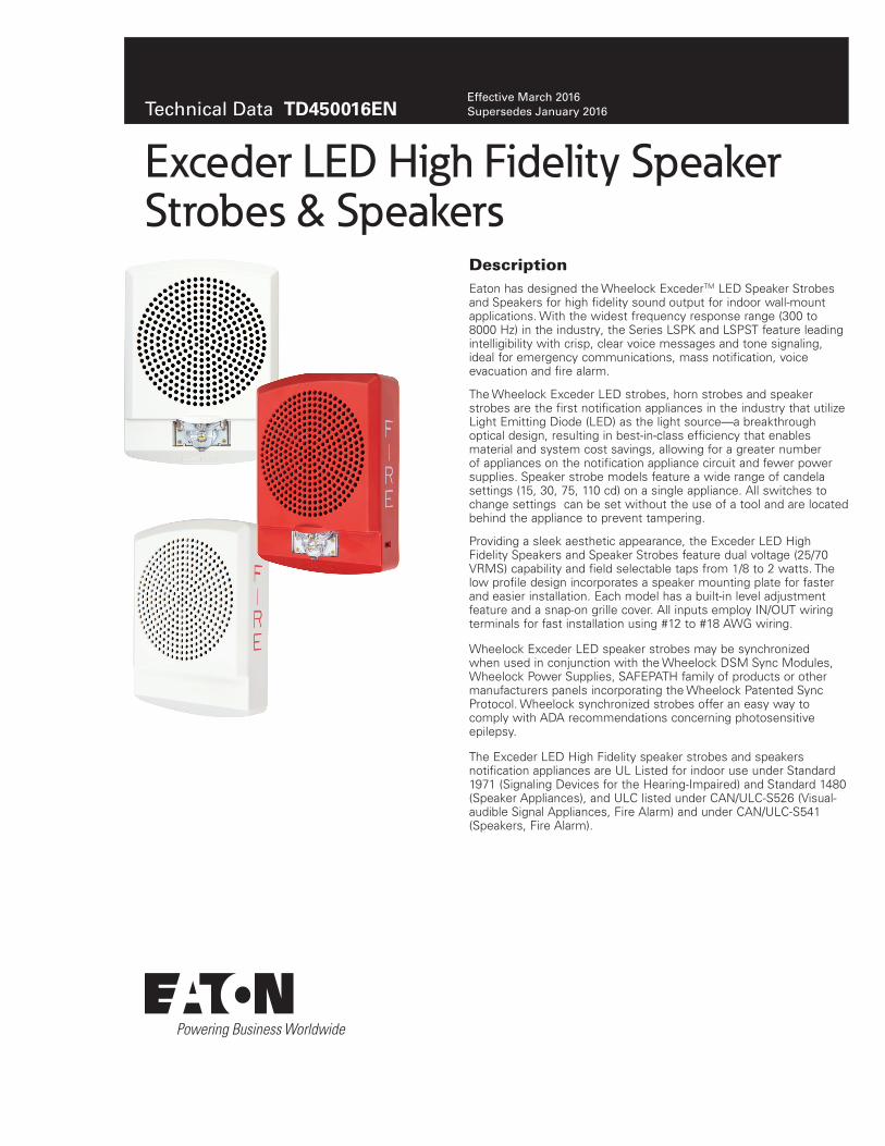
DescriptionEaton has designed the Wheelock ExcederTM LED Speaker Strobes and Speakers for high fidelity sound output for indoor wall-mount applications. With the widest frequency response range (300 to 8000 Hz) in the industry, the Series LSPK and LSPST feature leading intelligibility with crisp, clear voice messages and tone signaling, ideal for emergency communications, mass notification, voice evacuation and fire alarm.
The Wheelock Exceder LED strobes, horn strobes and speaker strobes are the first notification appliances in the industry that utilize Light Emitting Diode (LED) as the light source—a breakthrough optical design, resulting in best-in-class efficiency that enables material and system cost savings, allowing for a greater number of appliances on the notification appliance circuit and fewer power supplies. Speaker strobe models feature a wide range of candela settings (15, 30, 75, 110 cd) on a single appliance. All switches to change settings can be set without the use of a tool and are located behind the appliance to prevent tampering.
Providing a sleek aesthetic appearance, the Exceder LED High Fidelity Speakers and Speaker Strobes feature dual voltage (25/70 VRMS) capability and field selectable taps from 1/8 to 2 watts. The low profile design incorporates a speaker mounting plate for faster and easier installation. Each model has a built-in level adjustment feature and a snap-on grille cover. All inputs employ IN/OUT wiring terminals for fast installation using #12 to #18 AWG wiring.
Wheelock Exceder LED speaker strobes may be synchronized when used in conjunction with the Wheelock DSM Sync Modules, Wheelock Power Supplies, SAFEPATH family of products or other manufacturers panels incorporating the Wheelock Patented Sync Protocol. Wheelock synchronized strobes offer an easy way to comply with ADA recommendations concerning photosensitive epilepsy.
The Exceder LED High Fidelity speaker strobes and speakers notification appliances are UL Listed for indoor use under Standard 1971 (Signaling Devices for the Hearing-Impaired) and Standard 1480 (Speaker Appliances), and ULC listed under CAN/ULC-S526 (Visual-audible Signal Appliances, Fire Alarm) and under CAN/ULC-S541 (Speakers, Fire Alarm).
Exceder LED High Fidelity Speaker Strobes & Speakers
Technical Data TD450016ENEffective March 2016 Supersedes January 2016

2
Technical Data TD450016ENEffective March 2016
Exceder LED High Fidelity Speaker Strobes & Speakers
EATON www.eaton.com
Features • High Fidelity Sound Output
• High intelligibility at minimum wattage across a frequency range of 300 to 8000 Hz
• Energy Efficient• Patented LED technology provides industry’s lowest current
draw
• Fewer power supplies required, smaller wire gage, reduced wire runs
• Low-Profile Design• Smallest footprint with sleek, modern aesthetics
• Special Lettering Available• 4 Field Selectable Settings in 1 Device
• Select 15, 30, 75, 110 cd
• Field Selectable Taps• 1/8 watt up to 2 watts
• 25 or 70 VRMS operation
• Easy-to-Install• Finger slide switches--No tools needed for
setting changes
• Built-in level adjustment feature and snap-on grille cover
• IN/OUT screw terminals using #12 to #18 AWG wires
• Mounting Options include Exceder LSPKBB backboxes and 4” square, 2 1/8”deep backboxes
• Strobe Synchronization Components• Meet synchronizing standards with Wheelock’s DSM Sync
Modules, PS Power Supplies or SAFEPATH products
• Compliance• UL 1971, UL 1480, ULC-S526, ULC-S541
• California State Fire Marshal (CSFM)
• Low frequency requirements of UL 464 (520 Hz) to meet NFPA’s 520 Hz tone requirements for sleeping areas
• Factory Mutual (FM)
• ADA/NFPA/ANSI/OSHA
Note:N All CAUTIONS and WARNINGS are identified by the symbol . All warnings are printed in bold capital letters.
WARNINGPLEASE READ THESE SPECIFICATIONS AND ASSOCIATED INSTALLATION INSTRUCTIONS CAREFULLY BEFORE USING, SPECIFYING OR APPLYING THIS PRODUCT. VISIT WWW.COOPERNOTIFICATION.COM OR CONTACT EATON FOR THE CURRENT INSTALLATION INSTRUCTIONS. FAILURE TO COMPLY WITH ANY OF THESE INSTRUCTIONS, CAUTIONS OR WARNINGS COULD RESULT IN IMPROPER APPLICATION, INSTALLATION AND/OR OPERATION OF THESE PRODUCTS IN AN EMERGENCY SITUATION, WHICH COULD RESULT IN PROPERTY DAMAGE, AND SERIOUS INJURY OR DEATH TO YOU AND/OR OTHERS.
General Notes• Strobes are designed to flash at 1 flash per second minimum over
their “Regulated Voltage Range.” Note that NFPA-72 specifies a flash rate of 1 to 2 flashes per second and ADA Guidelines specify a flash rate of 1 to 3 flashes per second.
• All candela ratings represent minimum effective Strobe intensity based on UL 1971.
Drawings
Figurt 1. Wall Sptaktr SorNbt
Figurt 2. Wall Sptaktr
Tablt 1. Maximum RMS Currtno
Exceder LED High Fidelity Series Speaker Strobes
UL/ULC Max Current a
24VDC
ModelRegulated Voltage Range VDC 15 30 75 110
LSPST 16.0-33.0 0.030 0.040 0.115 0.200
a RMS current ratings are per UL maximum RMS method. UL max current rating is the maximum RMS current within the listed voltage range (16-33v for 24v units). For strobes the UL max current is usually at the minimum listed voltage (16v for 24v units). For audibles the max current is usually at the maximum listed voltage (33v for 24v units). For unfiltered FWR ratings, see installation instructions.

3
Technical Data TD450016ENEffective March 2016
Exceder LED High Fidelity Speaker Strobes & Speakers
EATON www.eaton.com
Tablt 2. UL/ULC Lisotd MNdtls and Raoings
UL Reverberant dBA at 10 Feet Anechoic dBA per CAN/ULC-S541-07
Model 1/8 watts 1/4 watts 1/2 watts 1 watts 2 watts 1/8 watts 1/4 watts 1/2 watts 1 watts 2 watts
LSPK Speaker LSPST Speaker Strobe
7575
7979
7979
8282
8585
7575
7979
8282
8585
8787
Tablt 3. SptcificaoiNn & Ordtring InfNrmaoiNn
Model Order Code Strobe Candela Red White LetteringSync w/ DSM or Wheelock Power Supplies
Speaker StrobesLSPSTRLSPSTW LSPSTW-AL LSPSTR-AL LSPSTW-NLSPSTR-N
0933 0934 0974 0975 09760977
15/30/75/110 15/30/75/110 15/30/75/110 15/30/75/110 15/30/75/110 15/30/75/110
X X
X
XX X
FIREFIRE ALERT ALERT No LetteringNo Lettering
XXXXXX
SpeakersLSPKRLSPKW LSPKR-N LSPKW-N LSPKW-ALLSPKR-AL
0758 0759 0795 0796 07660767
X X
X
X X X
FIREFIRE No Lettering No Lettering ALERTALERT
XXXXXX
BackboxesLSPKBB-RLSPKBB-W
0756 0757
X X
Tablt 4. SptcificaoiNns
PhysicalMaterial Red or white textured UV stabilized, colored impregnated engineered plastic. Exceeds 94V-0 UL flammabil-
ity rating Weight Speaker Strobe: 1.54 lbs (700g); Speaker Backbox: .44 lb (200g)Lens Light Emitting Diode (LED) in a rugged Lexan lensDimensions LSPK: 6.1”H x 4.56” W x 1.29” D; LSPST: 6.1”H x 4.56” W x 1.4” DOperating Temperature Indoor: 33.8°F to 120.2°F (0°C to 49°C) and maximum humidity of 93%
Mounting & Wire ConnectionsMounting (indoor only) Speakers and Speaker Strobes are for wall-mount applications only. Exceder LSPKBB backboxes or to 4”
square 2 1/8 deep backboxes Wire Connections #12 through #18 AWG
Power & GeneralOperating voltage 25/70 VRMS Strobe Output Rating UL 1971, ULC S526: Selectable 15, 30, 75, 110 candela outputStrobe Flash Rate Strobes are designed to flash at 1 flash per secondSynchronization Models Strobes can be synchronized with Wheelock’s DSM Sync Modules, PS Power Supplies or SAFEPATH prod-
ucts, using Wheelock patented sync protocolFrequency Range 300 Hz to 8000 Hz

Eaton is a registered trademark.
All other trademarks are property of their respective owners.
Exceder LED High Fidelity Speaker Strobes & Speakers
Eaton1000 Eaton BoulevardCleveland, OH 44122United StatesEaton.com
Life safety & mass notification solutions273 Branchport Ave.Long Branch, NJ 07740www.eaton.com/massnotification
© 2016 EatonAll Rights ReservedPrinted in USAPublication No. TD450016ENMarch 2016
Technical Data TD450016ENEffective March 2016
Architects and Engineers SpecificationsThe LED high fidelity speaker appliances shall be Wheelock® Exceder™ Series LSPK Speaker and LSPST Speaker Strobe for wall-mount applications with a low-profile design or approved equals. The speakers shall be UL Listed under UL 1480 for Fire Protective Service and speakers equipped with strobes shall be listed under UL 1971 for Emergency Devices for the Hearing-Impaired. In addition, the speaker strobes shall meet the requirements of FCC Part 15. All inputs shall be compatible with standard reverse polarity supervision of circuit wiring by a Fire Alarm Control Panel (FACP) with the ability to operate from 16 to 33 VDC.
All speakers shall be designed for a field selectable input of either 25 or 70 VRMS, with selectable power taps from 1/8 watt to 2 watts. All models shall have listed sound output of up to 84 dB at 10 feet and a listed frequency response of 300 to 8000 Hz. All inputs shall employ terminals that accept #12 to #18 AWG wire sizes. The Series LSPST Speaker Strobe appliances shall produce a flash rate of one (1) flash per second over the Regulated Voltage Range and shall incorporate a Light Emitting Diode (LED) as the light source with a rugged Lexan® lens. The Series shall be of low current design. Where Multi-Candela appliances are specified, the strobe intensity shall have 4 field selectable settings at 15, 30, 75, 110 candela for wall mount applications. The selector switch for selecting the candela shall be tamper resistant. Appliances with candela settings shall show the candela selection in a visible location at all times when installed.
The Series LSPK and LSPST shall be designed for indoor surface or flush mounting. Mounting options shall include LED speaker backboxes and to standard 4” square, 2 1/8” deep backboxes. The speaker and speaker strobe shall incorporate a speaker mounting plate with a snap-on grille cover and shall mount to standard electri-cal hardware requiring no additional trimplate or adapter. Continuity checking of the entire NAC circuit prior to attaching any notification appliances shall be allowed. Removal of an appliance shall result in a supervision fault condition by the Fire Alarm Control Panel (FACP). All notification appliances shall be backwards compatible.
The Series LSPK wall model shall have a low profile measuring 6.1” H x 4.56” W x 1.29” D. The Series LSPST wall model shall have a low profile measuring 6.1” H x 4.56” W x 1.4” D. Finish shall be red or white. Special lettering shall be available.
When synchronization is required, the appliance shall be compatible with Wheelock®’s DSM Sync Modules, PS Power Supplies, SAFEPATH products or other manufacturer’s panels with built-in Wheelock® Patented Sync Protocol. The strobes shall not drift out of synchronization at any time during operation. If the sync protocol fails to operate, the strobe shall revert to a non- synchronized flash-rate and still maintain (1) flash per second over its Regulated Voltage Range. The appliance shall also be designed so that the audible signal may be silenced while maintaining strobe activation when used with Wheelock® patented sync protocol.
The speaker shall be listed to the low frequency requirements of UL 464 (520 Hz) to meet NFPA’s 520 Hz tone requirements for sleeping areas.
UL 1971, UL 1480, ULC-S526, ULC-S541, CSFM, FM, FCC
Note:N Due to continuous development of our products, specifications and offerings are subject to change without notice in accordance with Cooper Wheelock Inc., dba Eaton standard terms and conditions.
WE ENCOURAGE AND SUPPORT NICET CERTIFICATION 3 YEAR WARRANTY

Description:
THE CITY OFNEW YORK
DEPARTMENT OF BUILDINGS
UL®
151-92-EE5946S5391 S2652
7125-0785:131 (ASWP)7125-0785:146 (ET70WP)7125-0785:156 (MTWP)7300-0785:154 (RSSWP)
Weatherproof Appliances - Series AH Audibles, AS Audible Strobes, MT Multitone Strobes, RSS Strobes and ET70 Speaker Strobes and Weatherproof Mounting Accessories
Designed for life safety, performance and reliability, Cooper Notification’s Wheelock cost effective weatherpoof notification appliances include:
Weatherproof Appliances SeriesStrobes RSSWP Horn Strobes ASWPHorns AH-24WP, AH-12WPMultitone Horn Strobes MTWPMultitone Horns MTSpeaker Strobes ET70WPSpeakers ET-1010
All strobe models are UL dual listed - meeting both UL1638 and UL1971 requirements. As dual listed appliances, these weatherproof strobes, horn strobes and speaker strobes are listed for outdoor applications under UL 1638 as well as under UL 1971, the Standard for Safety Signaling Devices for Hearing Impaired. With an extended temperature range of –31°F to 150°F (-35°C to 66°C), Wheelock weatherproof appliances meet or exceed UL outdoor test requirements for rain, humidity and corrosion resistance while providing multiple strobe intensity options, including the highest strobe ratings available for area coverage per NFPA 72 strobe spacing tables (up to 185 candela for wall mounting and 177 candela for ceiling mounting).To enable weatherproof mounting, Cooper Notification provides the industry’s widest choice of mounting options for surface or unique semi-flush installation. Models are available for surface mounting to Wheelock weatherproof backboxes on walls or ceilings. The optional WP-KIT allows the weatherproof backboxes (IOB, WPBB or WPSBB) to be mounted to a recessed electrical box for concealed conduit installation. For semi-flush installation, the WPA* and WFPA* kits allow a customer to mount the weatherproof appliances to a recessed electrical box without the need for an external weatherproof backbox. See the Backboxes, Plates and Gaskets Table on page three of this document for a summarization of these mounting options and the required accessories.
• Approvals include: UL Standards 1971, 1638, 464 and 1480 California State Fire Marshal (CSFM), New York City (MEA), Factory Mutual (FM), Chicago (BFP) and ULC . See agency approvals by model number on page two of this document• Compliance with the following requirements: NFPA, UFC, ANSI 117.1, OSHA Part 29, 1910.165, ADA• Weatherproof with extended temperature range of –40°F to 150°F (-40°C to 66°C)* • Dual Listed strobe models (UL 1638 and UL 1971) • Industry’s highest strobe candela options • Synchronize using the Wheelock Sync Modules or panels with built-in Wheelock Patented Sync Protocol• Models with field selectable tone, dBA and candela settings• Wall or ceiling mounting options• Surface of semi-flush mounting• IN/OUT wiring termination accepting two #12-18 AWG wires at each terminal
Features:
All models may be synchronized using the Wheelock DSM Sync Modules, Wheelock Power Supplies or other manufacturers panels incorporating the Wheelock Patented Sync Protocol. The horn output of horn strobes can be independently controlled on 2-wire circuits using the Wheelock patented sync protocol. MTWP horn strobe models are 4-wire appliances; the strobes can be synchronized while the audible can be connected to a coded fire alarm system or can be set to produce any of eight selectable tones.
The series RSSWP, ASWP, AH-24WP, MTWP-2475W, and MT-12/24 have UL / ULC approval down to -40°F. The ET-1010 and ET70WP have UL approval down to -40°F. The AH-12WP has UL approval down to -31°F.
Notification
*

NOTE: All CAUTIONS and WARNINGS are identified by the symbol . All warnings are printed in bold capital letters. WARNING: PLEASE READ THESE SPECIFICATIONS AND ASSOCIATED INSTALLATION INSTRUCTIONS CAREFULLY BEFORE USING, SPECIFYING OR
APPLYING THIS PRODUCT. VISIT WWW.COOPERNOTIFICATION.COM OR CONTACT COOPER WHEELOCK FOR THE CURRENT INSTALLATION INSTRUCTIONS. FAILURE TO COMPLY WITH ANY OF THESE INSTRUCTIONS, CAUTIONS OR WARNINGS COULD RESULT IN IMPROPER APPLICATION, INSTALLATION AND/OR OPERATION OF THESE PRODUCTS IN AN EMERGENCY SITUATION, WHICH COULD RESULT IN PROPERTY DAMAGE, AND SERIOUS INJURY OR DEATH TO YOU AND/OR OTHERS.
General Notes:• Strobes are designed to flash at 1 flash per second minimum over their UL Listed Regulated Voltage Range. • All candela ratings represent minimum effective Strobe intensity based on UL Standards 1971 and 1638 as indicated in candela ratings table.
Strobe Order CodeRSSWP-2475W-FR Red 9013RSSWP-2475W-FW White 3034RSSWP-24MCWH-FR Red 5161RSSWP-24MCWH-FW White 5165
Audible StrobeASWP-2475W-FR Red 9012ASWP-24MCWH-FR Red 5137ASWP-24MCWH-FW White 5140
Multi-tone StrobeMTWP-2475W-FR Red 8420MTWP-2475W-FW White 3112MTWP-24MCWH-FR Red 5132MTWP-24MCWH-FW White 5134
Speaker StrobeET70WP-2475W-FR Red 9077ET70WP-2475W-FW White 3179ET70WP-24185W-FR Red 4885ET70WP-24185W-FWET70WP-24135W-FR
WhiteRed
48914872
ET70WP-24135W-FW White 4875
UL Max. Current AH24 VDC 12 VDC
High (99) dBA 0.080 0.192Med (95) dBA 0.043 0.108Low (90) dBA 0.021 0.058
UL Max. Current (Audible)
MTWP/MT24 VDC
MT12 VDC
dBA HI STD HI STD Horn 0.108 0.044 0.177 0.034Bell 0.053 0.024 0.095 0.020March Time 0.104 0.038 0.142 0.034Code 3 Horn 0.091 0.035 0.142 0.034Code 3 Tone 0.075 0.035 0.105 0.021Slow Whoop 0.098 0.037 0.142 0.035Siren 0.104 0.036 0.152 0.030Hi/Lo 0.057 0.025 0.114 0.026
Strobe Order CodeRSSWP-2475C-FR Red 4338RSSWP-2475C-FW White 4446RSSWP-24MCCH-FR Red 5167RSSWP-24MCCH-FWWhite 5187
Audible StrobeASWP-2475C-FR Red 4251ASWP-2475C-FW White 4502ASWP-24MCCH-FR Red 5149ASWP-24MCCH-FW White 5157
Multi-tone StrobeMTWP-2475C-FR Red 4457MTWP-2475C-FW White 4478MTWP-24MCCH-FR Red 5102MTWP-24MCCH-FW White 5122
Speaker StrobeET70WP-2475C-FR Red 4452ET70WP-2475C-FW White 4454ET70WP-24177C-FR Red 4845ET70WP-24177C-FWET70WP-24115C-FR
WhiteRed
48594550
ET70WP-24115C-FW White 4732
Audible Order CodeAH-24WP-R Red 7416AH-12WP-R Red 7415
HornMT-12/24-R Red 5023
SpeakerET-1010-R Red 3135ET-1010-W White 3137
UL Reverberant dBA @ 10 FeetWatts 1/8 1/4 1/2 1 2 4 8ET-1010 77 80 83 86 87 92 94ET70WP 78 81 84 87 90 93 95
RSSWP MTWPMTWP
ET70WPASWP
RSSWPMT
ET-1010ASWP ET70WP
AH
Wall Mount Ceiling Mount Wall or Ceiling Mount
Model Number Agency Approvals
Strobe UL MEA CSFM FM BFPRSSWP-2475 X X X X -RSSWP-24MCWH X - X - -RSSWP-24MCCH X - X - -Audible StrobeASWP-2475 X X X X XASWP-MCWH X - X - -ASWP-MCCH X - X - -Multitone StrobeMTWP-2475 X X X X -MTWP-MCWH X - X - -MTWP-MCCH X - X - -Horns/AudiblesAH-24WP X X X X XAH-12WP X X X X XMT-12/24 X X X X XSpeaker StrobeET70WP-2475 X - X X -ET70WP-185 X - X X -ET70WP-177 X - X X -ET70WP-115 X - X X -ET70WP-135 X - X X -
Candela Ratings
Series UL 1971 UL 1638 @ 77°F
UL 1638 @ -40°F
RSS, ET70WP and MTWP UL Max Current
(Strobe Only)
ASWP
High Med Low
2475 30** 180 115 0.138 0.168 0.155 0.150
MCWH135 135 56 0.300 0.355 0.340 0.335
185 185 77 0.420 0.480 0.465 0.460
MCCH115 115 47 0.300 0.355 0.340 0.335
177 177 73 0.420 0.480 0.465 0.460
24185 185 185 77 0.420
24177 177 177 73 0.420**Wall mount rating only

NOTE: Due to continuous development of our products, specifications and offerings are subject to change without notice in accordance with Cooper Wheelock Inc. dba Cooper Notification standard terms and conditions.
Note: Models are available in Red or White. Contact Customer Service for Order Code and Delivery.#Refer to Data Sheet S7000 for Mounting Options
WFP WFPA IOB WPSBB WPBB WBB
Gasket Kit Order CodeWP-KIT 4486
Flush PlatesWFPA-R Red 4698WFPA-W White 4701WFP-R Red 4696WFP-W White 4697
BackboxesIOB-R* Red 5046IOB-W* White 5047WPSBB-R* Red 9751WPSBB-W* White 3033WPBB-R* Red 9014WPBB-W* White 4692WBB-R Red 2959WBB-W White 2960
FACP
NAC #1
NAC #2
SyncModule
or PS
PowerSupply
StrobeCircuit
AudibleCircuit
MTWP
DSM
+ OUT 2
+OUT 1
+ IN 1
+ IN 2
MINUS 1
MINUS 2
+-
-+
SYNC
AUDIBLE
STROBENAC
CIRCUITOUT
STROBENAC
CIRCUITRETURN
FACP
RSSWP ST
RSS ST
ASWP
ASWP
TO NEXTAPPLIANCE
OR EOLR
FROMPRECEDINGAPPLIANCEOR FACP
+ -STROBE AUDIBLE
+ -
RED
BLACK
+
- -
+
SERIES MTWP AUDIBLE APPLIANCE AND STROBE OPERATE IN UNISON. RED AND BLACK SHUNT-WIRES ARE SUPPLIED.
+-
+ -
+-
FROMPRECEDING
APPLIANCE ORFACP
TO NEXTAPPLIANCE
OR EOLR
SERIES RSSWP, ASWP, AHWP, MTWP AND MT-12/24 APPLIANCES
SERIES RSSWP/ASWP APPLIANCES SYNCHRONIZED W/DSM MODULE SINGLE CLASS “A” NAC CIRCUIT
SERIES MTWP APPLIANCES SYNCHRONIZED STROBE OPERATION WITH CODED FACP
Note: Strobe circuit requires constant voltage.
Wiring Diagrams
Mounting Accessories
Mounting Options: Backboxes, Plates, Gasket KitsSurface Mount Flush
MountExposed Conduit Concealed Conduit
RSSWP Strobes WPSBB WPSBB + WP-KIT WFP
ET70WP Speaker Strobes IOB IOB + WP-KIT WFP
ASWP Horn Strobes WPBB WPBB + WP-KIT WFPA
AHWP Horns WBB - WFP
ET-1010 Speakers WBB - WFP
MTWP Multitone Horn Strobes IOB IOB + WP-KIT WFP
Multitone Horn IOB IOB + WP-KIT WFP*IOB, WPSBB and WPBB models include weep holes and plug in the event that moisture may have entered the appliance

ARCHITECTS AND ENGINEERS SPECIFICATIONS
S9004 WP 06/11
GeneralWeatherproof notification appliances shall be UL listed for outdoor use. Weatherproof Strobe appliances shall be listed under UL Standard 1638 (Standard for Visual Signaling Appliances) for Indoor/Outdoor use and UL Standard 1971 (Standard for Safety Signaling Devices for Hearing Impaired). The appliances shall be available for optional wall mounting or ceiling mounting to weatherproof backboxes using either exposed conduit or concealed conduit, or semi-flush mounting to a recessed electrical box in walls or ceilings using Wheelock mounting accessories.
Weatherproof StrobesWeatherproof Strobe appliances shall produce a minimum flash rate of 60 flashes per minute over the UL Regulated Voltage Range of 16 to 33 VDC and shall incorporate a Xenon flashtube. The weatherproof strobes shall be available with UL 1971 candela ratings up to 185 cd for wall mounting and 177 cd for ceiling mounting. UL 1638 candela ratings up to 180 cd at 77°F shall be available. The strobes shall operate over an extended temperature range of –40°F to 150°F (-40°C to 66°C) and be listed for maximum humidity of 95% RH. Strobe inputs shall be polarized for compatibility with standard reverse polarity supervision of circuit wiring by a Fire Alarm Control Panel (FACP). Weatherproof Audibles and Audible/Strobe Combinations Weatherproof horns and multitone audibles shall be listed for Indoor/Outdoor use under UL Standard 464. The horns shall be able to produce a continuous output or a temporal code-3 output that can be synchronized. The horns shall have at least 3 sound level settings. Horn/Strobe combinations shall be able to be synchronized on a single NAC. Multitone audibles shall be able to produce 8 distinct tones selectable by dip switch and shall have at least 2 sound level settings. Multitone Audible/Strobe combinations shall have independent inputs for the audible and strobe. The strobes shall be able to be synchronized. The audibles shall be able to be coded when operated on a separate NAC.
Weatherproof Speakers and Speaker/StrobesWeatherproof speakers and speaker/strobes shall be listed for Indoor/Outdoor use under UL Standard 1480. All speakers shall provide field selectable taps for 1/8W to 8W operation for either 25 VRMS or 70 VRMS audio systems and shall incorporate a sealed back construction for extra protection and improved audibility. Speakers without strobes shall be Wheelock Series ET-1010. They shall be listed to produce up to 94 dBA and shall incorporate a vandal resistant grille design. Speaker with strobes shall be Wheelock Series ET70WP. They shall be available for surface or semi-flush mounting to walls or ceilings and shall be listed to produce up to 93 dBA.
Synchronization ModulesWhen synchronization of strobes or temporal code-3 audibles is required, the appliances shall be compatible with the Wheelock Series DSM Sync Modules, Wheelock Power Supplies or other manufacturers panels with built-in Wheelock Patented Sync Protocol. The strobes and audibles shall not drift out of synchronization at any time during operation. Series ASWP audibles and strobes shall be able to be synchronized on a 2-wire circuit with the ability to silence the audible if required. The strobes on Series MT multitone audible/strobe appliances shall be able to be synchronized and shall be able to be operated on a separate circuit from the audibles while the audible circuit is connected to a coded or continuous NAC.
Weatherproof Mounting AccessoriesWeatherproof mounting options shall include surface mounting or semi-flush mounting to walls or ceilings. Surface mounted appliances shall mount to Wheelock IOB, WBB, WPBB or WPSBB weatherproof backboxes using either exposed conduit or concealed conduit. For concealed conduit the weatherproof backbox shall be mounted to a recessed electrical box with Wheelock’s WP-KIT to provide a weatherproof seal for the electrical box. Semi-flush mounted appliances shall mount to a recessed electrical box using Wheelock WFP or WFPA flush plates to provide a weatherproof seal between the electrical box and the appliance.
WE ENCOURAGE AND SUPPORT NICET CERTIFICATION3 YEAR WARRANTY
NotificationCooper Notification is
NJ Location273 Branchport Ave.Long Branch, NJ 07740P: 800-631-2148F: 732-222-8707www.coopernotification.com

MH20845
®
Sealed Rechargeable
MODEL PS-1270 F112 Volt 7.0 Amp. Hr.
Battery
www.power-sonic.com BAT
T ERY
MUST B E RECYC
LED
PbNONSPILLABLE
L
HT H
W
6.35
4.75
3.2F1 F2
0.87.95
6.35
3.4
0.8
Tolerances are +/- 0.04 in. (+/- 1mm) and +/- 0.08 in. (+/- 2mm) for height dimensions. All data subject to change without notice.
Physical Dimensions: in (mm)
Features
• Absorbent Glass Mat (AGM) technology for superior performance
• Valve regulated, spill proof construction allows safe operation in any position
• Power/volume ratio yielding unrivaled energy density
• Rugged impact resistant ABS case and cover (UL94-HB)
• Approved for transport by air. D.O.T., I.A.T.A., F.A.A. and C.A.B. certified
• U.L. recognized under file number MH 20845
Performance Specifications
Nominal Voltage .......................................................12 volts (6 cells)
Nominal Capacity
20-hr. (350mA to 10.50 volts) .......................................... 7.00 AH
10-hr. (650mA to 10.50 volts) .......................................... 6.50 AH
5-hr. (1.2A to 10.20 volts) ............................................. 6.00 AH
1-hr. (4.5A to 9.00 volts) ............................................... 4.50 AH
15-min. (14A to 9.00 volts) ..................................................3.50 AH
Approximate Weight ......................................... 4.80 lbs. (2.18 kg)
Energy Density (20-hr. rate) ............... 1.49 W-h/in3 (90.95 W-h/l)
Specific Energy (20-hr. rate) ............ 17.50 W-h/lb (38.58 W-h/kg)
Internal Resistance (approx.) ..................................... 23 milliohms
Max Discharge Current (7 Min.) ............................... 21.0 amperes
Max Short-Duration Discharge Current (10 Sec.) .... 70.0 amperes
Shelf Life (% of nominal capacity at 68°F (20°C)
1 Month ................................................................................. 97%
3 Months ................................................................................ 91%
6 Months ............................................................................... 83%
Operating Temperature Range
Charge ................................................ -4°F (-20°C) to 122°F (50°C)
Discharge ............................................ -40°F (-40°C) to 140°F (60°C)
Case ..................................................................................ABS Plastic
Power-Sonic Chargers .................................PSC-12800A, 12800A-C
PS-1270
www.power-sonic.com To ensure safe and efficient operation always refer to the latest edition of our Technical Manual, as published on our website.All data subject to change without notice.
Terminals: (mm)
12 Volt 7.0 AH
L: 5.95 (151) W: 2.56 (65) H: 3.70 (94) HT: 3.86 (98)
• F1 - Quick disconnect tabs, 0.187” x 0.032”- Mate with AMP. INC. FASTON “187” series
• F2 - Quick disconnect tabs, 0.250” x 0.032” - Mate with AMP. INC FASTON “250” series
OR

CORPORATE OFFICE • 7550 Panasonic Way • San Diego, CA 92154 • USA • Tel: +1-619-661-2020 • Fax: +1-619-661-3650
CUSTOMER SERVICETel: +1-619-661-2030 Fax: [email protected]
INTERNATIONAL SALESTel: +1-650-364-5001 Fax: [email protected]
DOMESTIC SALESTel: +1-619-661-2020Fax: [email protected]
TECHNICAL SUPPORTTel: +1-619-661-2020 Fax: [email protected]
Contact Information www.power-sonic.com
0615 1M
© 2016. Power-Sonic Corporation. All rights reserved. All trademarks are the property of their respective owners.
ChargingCycle Applications: Limit initial current to 2.1A. Charge until battery voltage (under charge) reaches 14.4 to 14.7 volts at 68°F (20°C). Hold at 14.4 to 14.7 volts until current drops to under 70mA. Battery is fully charged under these conditions, and charger should be disconnected or switched to “float” voltage.
“Float” or “Stand-By” Service: Hold battery across constant voltage source of 13.5 to 13.8 volts continuously. When held at this voltage, the battery will seek its own current level and maintain itself in a fully charged condition.
Note: Due to the self-discharge characteristics of this type of battery, it is imperative that they be charged within 6 months of storage, otherwise permanent loss of capacity might occur as a result of sulfation.
ChargersPower-Sonic offers a wide range of chargers suitable for batteries up to 100AH. Please refer to the Charger Selection Guide in our specification sheets for “C-Series Switch Mode Chargers” and “Transformer Type A and F Series”. Please contact our Technical department for advice if you have difficulty in locating suitable models.
Cap
acity
Ret
entio
n R
atio
(%)
Standing Period (Months)
100
80
60
40
00 2 4 6 8 10 12 14 16 18 20
40oC(104oF)
30oC(86oF)
20oC(68oF)
5oC(41oF)
Charging is not necessary unless 100% of capacity is required.
Charging beforeuse is necessaryto help recoverfull capacity.
Charge may failto restore fullcapacity. Do notlet batteries reachthis state.
100
80
60
40
20
00 1 2 3 4
Ambient Temperature 20˚C (68˚F)
Float Charging Voltage2.25 - 2.30 V/Cell
Ret
entio
n C
apac
ity (%
)
Years
120
100
80
60
40
20
00 200 400 600 800 1000 1200
Number of Cycles
1. Discharge Current 0.2C (Final Voltage 1.7V/Cell)2. Charge Current: 0.1C3. Ambient Temperature: 20oC to 25oC (68oF to 77oF)R
eten
tion
Cap
acity
(%)
DischargeDepth 30%
DischargeDepth 100%
DischargeDepth 50%
Discharge Characteristics
Discharge Time vs. Discharge Current
Shelf Life & Storage
Life Characteristics in Stand-By Use
Life Characteristics in Cyclic Use
PS-1270 12 Volt 7.0 AH®
Further InformationPlease refer to our website www.power-sonic.com for a complete range of useful downloads, such as product catalogs, material safety data sheets (MSDS), ISO certification, etc..
13.0
12.0
11.0
10.0
9.0
8.0
14.0
Term
inal
Vol
tage
(V)
Ambient Temperature 20oC (68oF)
1.2 2.4 6 12 24 36 48 1 2 4 6 8 10 20 4 0
Discharge Time
FinalVoltage
min h
0.350.701.4
3.5
7.0
14
0.35 0.70 1.4 3.5 7.0 14Discharge Current (A)
201510
5
2
1
30
10
5
Dis
char
ge T
ime
40oC (104oF)20oC (68oF) 0oC (32oF)
min
h
10.2V
9.6V
9.0V
8.1V
FinalVoltage10.5V

Sealed Rechargeable
MODEL PS-12180 NB12 Volt 18.0 Amp. Hr.
Battery
www.power-sonic.com
BATT
ERY
MUST BE RECYC
LED
PbNONSPILLABLE
MH20845
®
L
HT H
W
Tolerances are +/- 0.04 in. (+/- 1mm) and +/- 0.08 in. (+/- 2mm) for height dimensions. All data subject to change without notice.
Physical Dimensions: in (mm)
Features
Absorbent Glass Mat (AGM) technology for superior performance
Valve regulated, spill proof construction allows safe operation in any position
Power/volume ratio yielding unrivaled energy density
Rugged impact resistant ABS case and cover (UL94-HB)
Approved for transport by air. D.O.T., I.A.T.A., F.A.A. and C.A.B. certified
U.L. recognized under file number MH 20845
•
•
•
•
•
•
Performance Specifications
Nominal Voltage ........................................................................ 12 volts (6 cells)
Nominal Capacity
20-hr. (900mA to 10.50 volts) ....................................................... 18.0 AH
10-hr. (1.7A to 10.50 volts) ............................................................. 17.0 AH
5-hr. (3.2A to 10.20 volts) ............................................................ 16.0 AH
1-hr. (11.1A to 9.00 volts) ............................................................. 11.1 AH
15-min. (34.3A to 9.00 volts) .............................................................. 8.58 AH
Approximate Weight ........................................................ 12.60 lbs. (5.72 kg)
Energy Density (20-hr. rate) ................................. 1.53 W-h/in3 (93.51 W-h/l)
Specific Energy (20-hr. rate) ............................... 17.14 W-h/lb (37.79 W-h/kg)
Internal Resistance (approx.) ...................................................... 14 milliohms
Max Discharge Current (7 Min.) ............................................... 54.0 amperes
Max Short-Duration Discharge Current (10 Sec.) ................ 180.0 amperes
Shelf Life (% of nominal capacity at 68°F (20°C))
1 Month ...................................................................................................... 97%
3 Months ..................................................................................................... 91%
6 Months .................................................................................................... 83%
Operating Temperature Range
Charge .. ........................................................... -4°F (-20°C) to 122°F (50°C)
Discharge ....................................................... -40°F (-40°C) to 140°F (60°C)
Case ...................................................................................................... ABS Plastic
Power-Sonic Chargers ....PSC-122000A, 124000A, 122000A-C, 124000A-C
PS-12180
www.power-sonic.comTo ensure safe and efficient operation always refer to the latest edition of our Technical Manual, as published on our website.All data subject to change without notice.
Terminals (mm)
12 Volt 18.0 AH
L: 7.13 (181) W: 3.00 (76) H: 6.59 (167) HT: 6.59 (167)
F2 - Quick disconnect tabs, 0.250” x 0.032” - Mate with AMP. INC FASTON “250” series NB2: Tin plated brass post with nut & bolt connectors T12 - Threaded insert with 5mm stud
•
•
•
14
4.5
126
2
7.95
6.35
3.4
0.8
12mm
F2
T12
NB
6mm
M5

CORPORATE OFFICE • 7550 Panasonic Way • San Diego, CA 92154 • USA • Tel: +1-619-661-2020 • Fax: +1-619-661-3650
CUSTOMER SERVICETel: +1-619-661-2030 Fax: [email protected]
INTERNATIONAL SALESTel: +1-650-364-5001 Fax: [email protected]
DOMESTIC SALESTel: +1-619-661-2020Fax: [email protected]
TECHNICAL SUPPORTTel: +1-619-661-2020 Fax: [email protected]
Contact Information www.power-sonic.com
0812 1M
© 2012. Power-Sonic Corporation. All rights reserved. All trademarks are the property of their respective owners.
ChargingCycle Applications: Limit initial current to 5.4A. Charge until battery voltage (under charge) reaches 14.4 to 14.7 volts at 68°F (20°C). Hold at 14.4 to 14.7 volts until current drops to under 180mA. Battery is fully charged under these conditions, and charger should be disconnected or switched to “float” voltage.
“Float” or “Stand-By” Service: Hold battery across constant voltage source of 13.5 to 13.8 volts continuously. When held at this voltage, the battery will seek its own current level and maintain itself in a fully charged condition.
Note: Due to the self-discharge characteristics of this type of battery, it is imperative that they be charged within 6 months of storage, otherwise permanent loss of capacity might occur as a result of sulfation.
ChargersPower-Sonic offers a wide range of chargers suitable for batteries up to 100AH. Please refer to the Charger Selection Guide in our specification sheets for “C-Series Switch Mode Chargers” and “Transformer Type A and F Series”. Please contact our Technical department for advice if you have difficulty in locating suitable models.
Cap
acity
Ret
entio
nR
atio
(%)
Standing Period (Months)
100
80
60
40
00 2 4 6 8 10 12 14 16 18 20
40oC(104oF)
30oC(86oF)
20oC(68oF)
5oC(41oF)
Charging is notnecessary unless 100% of capacity is required.
Charging beforeuse is necessaryto help recoverfull capacity.
Charge may failto restore fullcapacity. Do notlet batteries reachthis state.
100
80
60
40
20
00 1 2 3 4
Ambient Temperature 20˚C (68˚F)
Float Charging Voltage2.25 - 2.30 V/Cell
Ret
entio
nC
apac
ity(%
)
Years
120
100
80
60
40
20
00 200 400 600 800 1000 1200
Number of Cycles
1. Discharge Current 0.2C (Final Voltage 1.7V/Cell)2. Charge Current: 0.1C3. Ambient Temperature: 20oC to 25oC (68oF to 77oF)R
eten
tion
Cap
acity
(%)
DischargeDepth 30%
DischargeDepth 100%
DischargeDepth 50%
Discharge Characteristics
Discharge Time vs. Discharge Current
Shelf Life & Storage
Life Characteristics in Stand-By Use
Life Characteristics in Cyclic Use
PS-12180 12 Volt 18.0 AH®
Further InformationPlease refer to our website www.power-sonic.com for a complete range of useful downloads, such as product catalogs, material safety data sheets (MSDS), ISO certification, etc..
13.0
12.0
11.0
10.0
9.0
8.0
14.0
Term
inal
Vol
tage
(V)
Ambient Temperature 20oC (68oF)
1.2 2.4 6 12 24 36 48 1 2 4 6 8 10 20 4 0
Discharge Time
FinalVoltage
min h
0.901.83.6
9.0
18
36
0.90 1.8 3.6 9.0 18 36Discharge Current (A)
201510
5
2
1
30
10
5
Dis
char
ge T
ime
40oC (104oF)20oC (68oF) 0oC (32oF)
min
h
10.2V
9.6V
9.0V
8.1V
FinalVoltage10.5V

Sealed Rechargeable
MODEL PS-121000 U12 Volt 100.0 Amp. Hr.
Battery
www.power-sonic.com
BAT
T ERY
MUST BE RECYC
LED
PbNONSPILLABLE
MH20845
®
L
HT H
W
Tolerances are +/- 0.04 in. (+/- 1mm) and +/- 0.08 in. (+/- 2mm) for height dimensions. All data subject to change without notice.
Physical Dimensions: in (mm)
Features
• Absorbent Glass Mat (AGM) technology for superior performance
• Valve regulated, spill proof construction allows safe operation in any position
• Power/volume ratio yielding unrivaled energy density
• Rugged impact resistant ABS case and cover (UL94-HB)
• Integrated ABS carrying handles for ease of movement
• Approved for transport by air. D.O.T., I.A.T.A., F.A.A. and C.A.B. certified
• U.L. recognized under file number MH 20845
Performance Specifications
Nominal Voltage .......................................................12 volts (6 cells)
Nominal Capacity
20-hr. (5A to 10.50 volts) .............................................. 100.0 AH
10-hr. (9.2A to 10.50 volts) ............................................. 92.0 AH
5-hr. (15.8A to 10.20 volts) ........................................... 79.0 AH
1-hr. (55.2A to 9.00 volts) ............................................. 55.2 AH
15-min. (175A to 9.00 volts) ................................................43.8 AH
Approximate Weight ..................................... 68.00 lbs. (30.84 kg)
Energy Density (20-hr. rate) ............. 1.86 W-h/in3 (113.45 W-h/l)
Specific Energy (20-hr. rate) ............ 17.65 W-h/lb (38.91 W-h/kg)
Internal Resistance (approx.) ....................................... 5 milliohms
Max Discharge Current (7 Min.) ............................. 300.0 amperes
Max Short-Duration Discharge Current (10 Sec.) .. 750.0 amperes
Shelf Life (% of nominal capacity at 68°F (20°C)
1 Month ................................................................................. 97%
3 Months ................................................................................ 91%
6 Months ............................................................................... 83%
Operating Temperature Range
Charge ................................................ -4°F (-20°C) to 122°F (50°C)
Discharge ............................................ -40°F (-40°C) to 140°F (60°C)
Case ..................................................................................ABS Plastic
Power-Sonic Chargers ...........................................PSC-1210000A-C
www.power-sonic.comTo ensure safe and efficient operation always refer to the latest edition of our Technical Manual, as published on our website.All data subject to change without notice.
Terminals: in (mm)
L: 12.00 (305) W: 6.60 (168) H: 8.15 (207) HT: 8.98 (228)
18 22
17.4
10 10
9 9
8.5
8.5
13
18 2215.9
13
U: Positive Terminal
T6
U: Negative Terminal
16
6
M6
• U: Universal terminals: Heavy-duty posts with ‘nut & bolt’ fasteners
• T6: Threaded insert w. 6 mm stud fastener
PS-121000 12 Volt 100.0 AH

CORPORATE OFFICE • 7550 Panasonic Way • San Diego, CA 92154 • USA • Tel: +1-619-661-2020 • Fax: +1-619-661-3650
CUSTOMER SERVICETel: +1-619-661-2030 Fax: [email protected]
INTERNATIONAL SALESTel: +1-650-364-5001 Fax: [email protected]
DOMESTIC SALESTel: +1-619-661-2020Fax: [email protected]
TECHNICAL SUPPORTTel: +1-619-661-2020 Fax: [email protected]
Contact Information www.power-sonic.com
0114 1M
© 2013. Power-Sonic Corporation. All rights reserved. All trademarks are the property of their respective owners.
ChargingCycle Applications: Limit initial current to 20A. Charge until battery voltage (under charge) reaches 14.4 to 14.7 volts at 68°F (20°C). Hold at 14.4 to 14.7 volts until current drops to under 1A. Battery is fully charged under these conditions, and charger should be disconnected or switched to “float” voltage.
“Float” or “Stand-By” Service: Hold battery across constant voltage source of 13.5 to 13.8 volts continuously. When held at this voltage, the battery will seek its own current level and maintain itself in a fully charged condition.
Note: Due to the self-discharge characteristics of this type of battery, it is imperative that they be charged within 6 months of storage, otherwise permanent loss of capacity might occur as a result of sulfation.
ChargersPower-Sonic offers a wide range of chargers suitable for batteries up to 100AH. Please refer to the Charger Selection Guide in our specification sheets for “C-Series Switch Mode Chargers” and “Transformer Type A and F Series”. Please contact our Technical department for advice if you have difficulty in locating suitable models.
Cap
acity
Ret
entio
n R
atio
(%)
Standing Period (Months)
100
80
60
40
00 2 4 6 8 10 12 14 16 18 20
40oC(104oF)
30oC(86oF)
20oC(68oF)
5oC(41oF)
Charging is not necessary unless 100% of capacity is required.
Charging beforeuse is necessaryto help recoverfull capacity.
Charge may failto restore fullcapacity. Do notlet batteries reachthis state.
Discharge CharacteristicsDischarge Time vs. Discharge Current
Shelf Life & Storage
PS-121000 12 Volt 100.0 AH®
Further InformationPlease refer to our website www.power-sonic.com for a complete range of useful downloads, such as product catalogs, material safety data sheets (MSDS), ISO certification, etc..
13.0
12.0
11.0
10.0
9.0
8.0
14.0
Constant Power Discharge Ratings
MODEL FINALVOLTAGE
WATTS PER CELL @ 25° C
5 MIN 10 MIN 15 MIN 20 MIN 30 MIN 45 MIN 60 MIN
PS-121000
1.75 550 395 312 267 207 152 128
1.70 586 413 324 277 212 155 129
1.67 605 421 330 283 215 158 130
Term
inal
Vol
tage
(V)
Ambient Temperature 20oC (68oF)
1.2 2.4 6 12 24 36 48 1 2 4 6 8 10 20 4 0
Discharge Time
FinalVoltage
min h
5.01020
50
100
200
5.0 10 20 50 100 200Discharge Current (A)
201510
5
2
1
30
10
5
Dis
char
ge T
ime
40oC (104oF)20oC (68oF) 0oC (32oF)
min
h
10.2V
9.6V
9.0V
8.1V
FinalVoltage10.5V

Document 51981:A 08/16/02
The BB-100 Cabinet is lockable, hinged on the left, andshipped assembled. It can mount a power supply and up totwo PS-12100 100-AH batteries. Below are the cabinetdimensions for installation.
BB-100 Cabinet51981Revision A
08/16/2002ECN 02-361
BB10
0_Ba
ckbo
x.wm
f
The total weight of a fully loadedBB-100 will exceed 175 pounds.Additional support may be requiredwhen mounting this cabinet to awall.
BB-100 Cabinet
BB-100 Cabinet Door
Note: All 0.437 in. diameter mountingholes will accommodate up to 3/8 in.mounting hardware.
(See note.)
BB10
0_Do
or.w
mf