Umbrello UML Modeller Handbook - kcir.pwr.edu.plkreczmer/kpo/pomoce/umbrello-handbook.pdfUmbrello...
41
Umbrello UML Modeller Handbook
Transcript of Umbrello UML Modeller Handbook - kcir.pwr.edu.plkreczmer/kpo/pomoce/umbrello-handbook.pdfUmbrello...
Umbrello UML ModellerHandbook

Umbrello UML Modeller Handbook
2
Contents
1 Introduction 1
2 UML Basics 32.1 About UML . . . . . . . . . . . . . . . . . . . . . . . . . . . . . . 32.2 UML Elements . . . . . . . . . . . . . . . . . . . . . . . . . . . . . 4
2.2.1 Use Case Diagram . . . . . . . . . . . . . . . . . . . . . . 4
2.2.1.1 Use Case . . . . . . . . . . . . . . . . . . . . . . 52.2.1.2 Actor . . . . . . . . . . . . . . . . . . . . . . . . 62.2.1.3 Use Case Description . . . . . . . . . . . . . . . 6
2.2.2 Class Diagram . . . . . . . . . . . . . . . . . . . . . . . . . 6
2.2.2.1 Class . . . . . . . . . . . . . . . . . . . . . . . . . 72.2.2.1.1 Attributes . . . . . . . . . . . . . . . . 82.2.2.1.2 Operations . . . . . . . . . . . . . . . . 8
2.2.2.1.3 Templates . . . . . . . . . . . . . . . . 8
2.2.2.2 Class Associations . . . . . . . . . . . . . . . . . 82.2.2.2.1 Generalization . . . . . . . . . . . . . . 82.2.2.2.2 Associations . . . . . . . . . . . . . . . 92.2.2.2.3 Aggregation . . . . . . . . . . . . . . . 9
2.2.2.2.4 Composition . . . . . . . . . . . . . . . 10
2.2.2.3 Other Class Diagram Items . . . . . . . . . . . . 10
2.2.2.3.1 Interfaces . . . . . . . . . . . . . . . . . 102.2.2.3.2 Datatypes . . . . . . . . . . . . . . . . . 10
2.2.2.3.3 Enums . . . . . . . . . . . . . . . . . . 102.2.2.3.4 Packages . . . . . . . . . . . . . . . . . 10
2.2.3 Sequence Diagrams . . . . . . . . . . . . . . . . . . . . . . 11
2.2.4 Collaboration Diagrams . . . . . . . . . . . . . . . . . . . 11
2.2.5 State Diagram . . . . . . . . . . . . . . . . . . . . . . . . . 12
Umbrello UML Modeller Handbook
2.2.5.1 State . . . . . . . . . . . . . . . . . . . . . . . . . 142.2.6 Activity Diagram . . . . . . . . . . . . . . . . . . . . . . . 14
2.2.6.1 Activity . . . . . . . . . . . . . . . . . . . . . . . 15
2.2.7 Helper Elements . . . . . . . . . . . . . . . . . . . . . . . 15
2.2.8 Component Diagrams . . . . . . . . . . . . . . . . . . . . 15
2.2.9 Deployment Diagrams . . . . . . . . . . . . . . . . . . . . 16
3 Working with Umbrello UML Modeller 17
3.1 User Interface . . . . . . . . . . . . . . . . . . . . . . . . . . . . . 173.1.1 Tree View . . . . . . . . . . . . . . . . . . . . . . . . . . . 183.1.2 Documentation Window . . . . . . . . . . . . . . . . . . . 183.1.3 Work Area . . . . . . . . . . . . . . . . . . . . . . . . . . . 19
3.2 Creating, Loading and Saving Models . . . . . . . . . . . . . . . 19
3.2.1 New Model . . . . . . . . . . . . . . . . . . . . . . . . . . 193.2.2 Save Model . . . . . . . . . . . . . . . . . . . . . . . . . . 193.2.3 Load Model . . . . . . . . . . . . . . . . . . . . . . . . . . 19
3.3 Editing Models . . . . . . . . . . . . . . . . . . . . . . . . . . . . 20
3.4 Adding and Removing Diagrams . . . . . . . . . . . . . . . . . . 20
3.4.1 Creating Diagrams . . . . . . . . . . . . . . . . . . . . . . 20
3.4.2 Removing Diagrams . . . . . . . . . . . . . . . . . . . . . 21
3.4.3 Renaming Diagrams . . . . . . . . . . . . . . . . . . . . . 21
3.5 Editing Diagrams . . . . . . . . . . . . . . . . . . . . . . . . . . . 21
3.5.1 Insert Elements . . . . . . . . . . . . . . . . . . . . . . . . 213.5.2 Deleting Elements . . . . . . . . . . . . . . . . . . . . . . 22
3.5.3 Editing Elements . . . . . . . . . . . . . . . . . . . . . . . 22
3.5.4 Editing Classes . . . . . . . . . . . . . . . . . . . . . . . . 23
3.5.4.1 Class General Settings . . . . . . . . . . . . . . . 23
3.5.4.2 Class Attribute Settings . . . . . . . . . . . . . . 23
3.5.4.3 Class Operations Settings . . . . . . . . . . . . . 23
3.5.4.4 Class Template Settings . . . . . . . . . . . . . . 24
3.5.4.5 Class Associations Page . . . . . . . . . . . . . . 24
3.5.4.6 Class Display Page . . . . . . . . . . . . . . . . 24
3.5.4.7 Class Color Page . . . . . . . . . . . . . . . . . . 24
3.5.5 Associations . . . . . . . . . . . . . . . . . . . . . . . . . . 243.5.5.1 Anchor Points . . . . . . . . . . . . . . . . . . . 25
3.5.6 Notes, Text and Boxes . . . . . . . . . . . . . . . . . . . . 253.5.6.1 Anchors . . . . . . . . . . . . . . . . . . . . . . . 25
4
Umbrello UML Modeller Handbook
4 Code Import and Code Generation 27
4.1 Code Generation . . . . . . . . . . . . . . . . . . . . . . . . . . . 274.1.1 Generating Code . . . . . . . . . . . . . . . . . . . . . . . 27
4.1.1.1 Generation Options . . . . . . . . . . . . . . . . 29
4.1.1.1.1 Code Verbosity . . . . . . . . . . . . . 29
4.1.1.1.2 Folders . . . . . . . . . . . . . . . . . . 294.1.1.1.3 Overwrite Policy . . . . . . . . . . . . 29
4.1.1.1.4 Language . . . . . . . . . . . . . . . . . 29
4.1.1.2 Generation Wizard Generation . . . . . . . . . . 294.2 Code Import . . . . . . . . . . . . . . . . . . . . . . . . . . . . . . 30
5 Other Features 315.1 Other Umbrello UML Modeller Features . . . . . . . . . . . . . . 31
5.1.1 Copying objects as PNG images . . . . . . . . . . . . . . 31
5.1.2 Exporting to an Image . . . . . . . . . . . . . . . . . . . . 31
5.1.3 Printing . . . . . . . . . . . . . . . . . . . . . . . . . . . . 31
5.1.4 Logical Folders . . . . . . . . . . . . . . . . . . . . . . . . 32
6 Authors and History 33
7 Copyright 35
5

Abstract
Umbrello UML Modeller helps the software development process by using theindustry standard Unified Modelling Language (UML) to enable you to creatediagrams for designing and documenting your systems.
Umbrello UML Modeller Handbook
Chapter 1
Introduction
Umbrello UML Modeller is a UML diagram tool that can support you in thesoftware development process. Especially during the analysis and design phasesof this process, Umbrello UML Modeller will help you to get a high qualityproduct. UML can also be used to document your software designs to helpyou and your fellow developers.
Having a good model of your software is the best way to communicate withother developers working on the project and with your customers. A goodmodel is extremely important for medium and big-size projects, but it is alsovery useful for small ones. Even if you are working on a small one man projectyou will benefit from a good model because it will give you an overview thatwill help you code things right the first time.
UML is the diagramming language used to describing such models. You canrepresent your ideas in UML using different types of diagrams. Umbrello UMLModeller 1.2 supports the following types:
• Class Diagram
• Sequence Diagram
• Collaboration Diagram
• Use Case Diagram
• State Diagram
• Activity Diagram
• Component Diagram
• Deployment Diagram
1

Umbrello UML Modeller Handbook
More information about UML can be found at the website of OMG, http://www.omg.orgwho create the UML standard.We hope you enjoy Umbrello UML Modeller and that it helps you create highquality software. Umbrello UML Modeller is Free Software and available at nocost, the only thing we ask from you is to report any bugs, problems, or sugges-tions to the Umbrello UML Modeller developers at [email protected] http://bugs.kde.org.
2
Umbrello UML Modeller Handbook
Chapter 2
UML Basics
2.1 About UML
This chapter will give you a quick overview of the basics of UML. Keep in mindthat this is not a comprehensive tutorial on UML but rather a brief introductionto UML which can be read as a UML tutorial. If you would like to learn moreabout the Unified Modelling Language, or in general about software analysisand design, refer to one of the many books available on the topic. There arealso a lot of tutorials on the Internet which you can take as a starting point.
The Unified Modelling Language (UML) is a diagramming language or nota-tion to specify, visualize and document models of Object Orientated softwaresystems. UML is not a development method, that means it does not tell youwhat to do first and what to do next or how to design your system, but ithelps you to visualize your design and communicate with others. UML is con-trolled by the Object Management Group (OMG) and is the industry standardfor graphically describing software.
UML is designed for Object Orientated software design and has limited use forother programming paradigms.
UML is composed of many model elements that represent the different partsof a software system. The UML elements are used to create diagrams, whichrepresent a certain part, or a point of view of the system. The following typesof diagrams are supported by Umbrello UML Modeller:
• Use Case Diagrams show actors (people or other users of the system), usecases (the scenarios when they use the system), and their relationships
• Class Diagrams show classes and the relationships between them
• Sequence Diagrams show objects and a sequence of method calls they make toother objects.
3

Umbrello UML Modeller Handbook
• Collaboration Diagrams show objects and their relationship, putting emphasison the objects that participate in the message exchange
• State Diagrams show states, state changes and events in an object or a part ofthe system
• Activity Diagrams show activities and the changes from one activity to an-other with the events occurring in some part of the system
• Component Diagrams show the high level programming components (such asKParts or Java Beans).
• Deployment Diagrams show the instances of the components and their rela-tionships.
2.2 UML Elements
2.2.1 Use Case Diagram
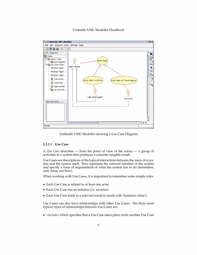
Use Case Diagrams describe the relationships and dependencies between agroup of Use Cases and the Actors participating in the process.
It is important to notice that Use Case Diagrams are not suited to represent thedesign, and cannot describe the internals of a system. Use Case Diagrams aremeant to facilitate the communication with the future users of the system, andwith the customer, and are specially helpful to determine the required featuresthe system is to have. Use Case Diagrams tell, what the system should do butdo not — and cannot — specify how this is to be achieved.
4
Umbrello UML Modeller Handbook
Umbrello UML Modeller showing a Use Case Diagram
2.2.1.1 Use Case
A Use Case describes — from the point of view of the actors — a group ofactivities in a system that produces a concrete, tangible result.
Use Cases are descriptions of the typical interactions between the users of a sys-tem and the system itself. They represent the external interface of the systemand specify a form of requirements of what the system has to do (remember,only what, not how).
When working with Use Cases, it is important to remember some simple rules:
• Each Use Case is related to at least one actor
• Each Use Case has an initiator (i.e. an actor)
• Each Use Case leads to a relevant result (a result with ‘business value’)
Use Cases can also have relationships with other Use Cases. The three mosttypical types of relationships between Use Cases are:
• «include» which specifies that a Use Case takes place inside another Use Case
5
Umbrello UML Modeller Handbook
• «extends» which specifies that in certain situations, or at some point (calledan extension point) a Use Case will be extended by another.
• Generalization specifies that a Use Case inherits the characteristics of the ‘Super’-Use Case, and can override some of them or add new ones in a similar wayas the inheritance between classes.
2.2.1.2 Actor
An actor is an external entity (outside of the system) that interacts with thesystem by participating (and often initiating) a Use Case. Actors can be inreal life people (for example users of the system), other computer systems orexternal events.Actors do not represent the physical people or systems, but their role. Thismeans that when a person interacts with the system in different ways (assum-ing different roles) he will be represented by several actors. For example aperson that gives customer support by the telephone and takes orders fromthe customer into the system would be represented by an actor ‘Support Staff’and an actor ‘Sales Representative’
2.2.1.3 Use Case Description
Use Case Descriptions are textual narratives of the Use Case. They usually takethe form of a note or a document that is somehow linked to the Use Case, andexplains the processes or activities that take place in the Use Case.
2.2.2 Class Diagram
Class Diagrams show the different classes that make up a system and how theyrelate to each other. Class Diagrams are said to be ‘static’ diagrams becausethey show the classes, along with their methods and attributes as well as thestatic relationships between them: which classes ‘know’ about which classesor which classes ‘are part’ of another class, but do not show the method callsbetween them.
6
Umbrello UML Modeller Handbook
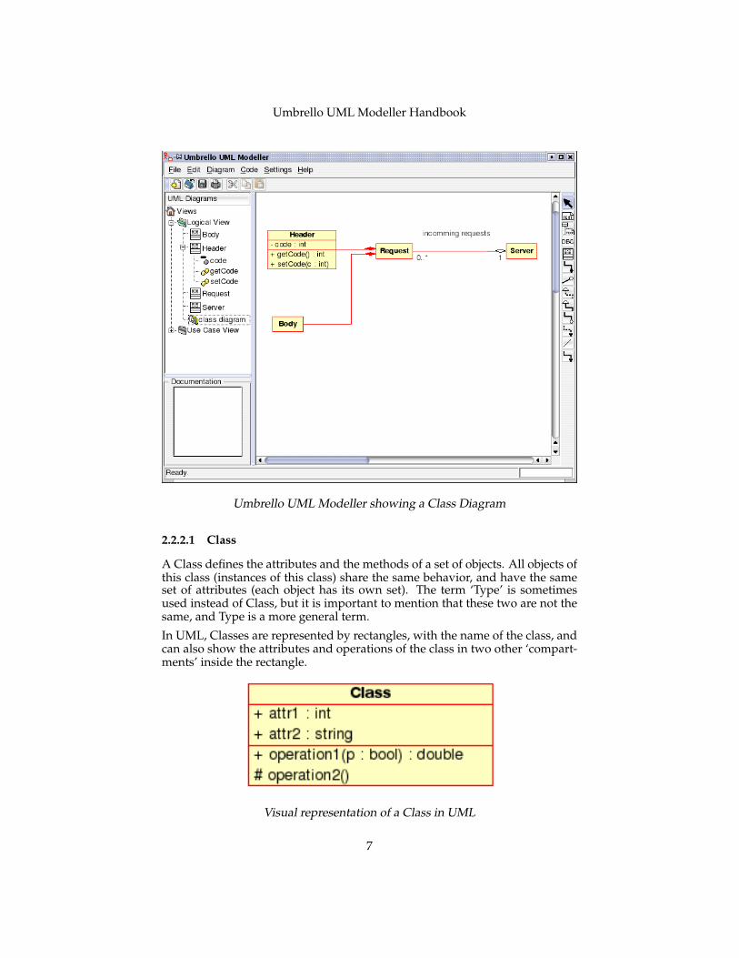
Umbrello UML Modeller showing a Class Diagram
2.2.2.1 Class
A Class defines the attributes and the methods of a set of objects. All objects ofthis class (instances of this class) share the same behavior, and have the sameset of attributes (each object has its own set). The term ‘Type’ is sometimesused instead of Class, but it is important to mention that these two are not thesame, and Type is a more general term.
In UML, Classes are represented by rectangles, with the name of the class, andcan also show the attributes and operations of the class in two other ‘compart-ments’ inside the rectangle.
Visual representation of a Class in UML
7
Umbrello UML Modeller Handbook
2.2.2.1.1 Attributes In UML, Attributes are shown with at least their name,and can also show their type, initial value and other properties. Attributes canalso be displayed with their visibility:
• + Stands for public attributes
• # Stands for protected attributes
• - Stands for private attributes
2.2.2.1.2 Operations Operations (methods) are also displayed with at leasttheir name, and can also show their parameters and return types. Operationscan, just as Attributes, display their visibility:
• + Stands for public operations
• # Stands for protected operations
• - Stands for private operations
2.2.2.1.3 Templates Classes can have templates, a value which is used foran unspecified class or type. The template type is specified when a class isinitiated (i.e. an object is created). Templates exist in modern C++ and will beintroduced in Java 1.5 where they will be called Generics.
2.2.2.2 Class Associations
Classes can relate (be associated with) to each other in different ways:
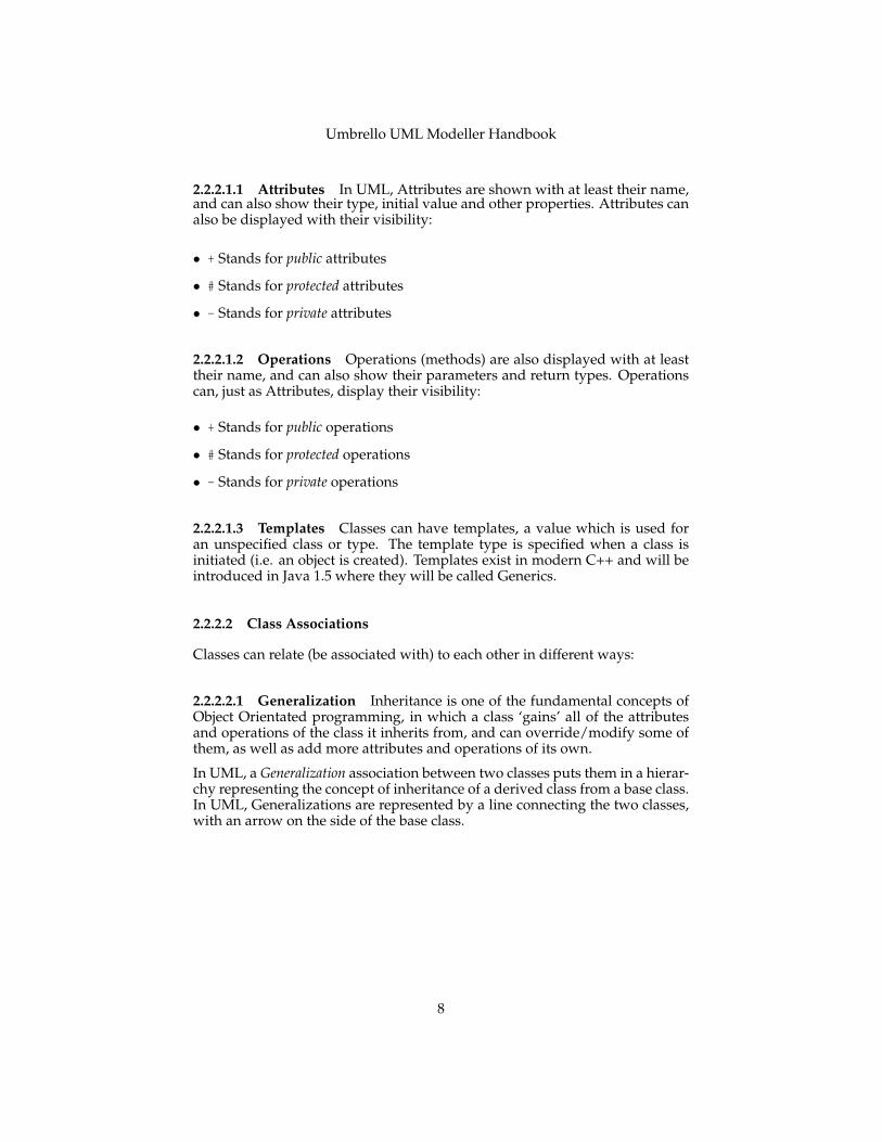
2.2.2.2.1 Generalization Inheritance is one of the fundamental concepts ofObject Orientated programming, in which a class ‘gains’ all of the attributesand operations of the class it inherits from, and can override/modify some ofthem, as well as add more attributes and operations of its own.
In UML, a Generalization association between two classes puts them in a hierar-chy representing the concept of inheritance of a derived class from a base class.In UML, Generalizations are represented by a line connecting the two classes,with an arrow on the side of the base class.
8
Umbrello UML Modeller Handbook
Visual representation of a generalization in UML
2.2.2.2.2 Associations An association represents a relationship between classes,and gives the common semantics and structure for many types of ‘connections’between objects.
Associations are the mechanism that allows objects to communicate to eachother. It describes the connection between different classes (the connection be-tween the actual objects is called object connection, or link.
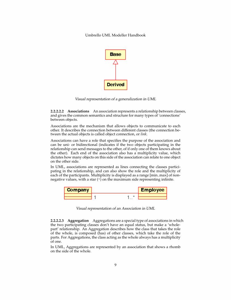
Associations can have a role that specifies the purpose of the association andcan be uni- or bidirectional (indicates if the two objects participating in therelationship can send messages to the other, of if only one of them knows aboutthe other). Each end of the association also has a multiplicity value, whichdictates how many objects on this side of the association can relate to one objecton the other side.In UML, associations are represented as lines connecting the classes partici-pating in the relationship, and can also show the role and the multiplicity ofeach of the participants. Multiplicity is displayed as a range [min..max] of non-negative values, with a star (*) on the maximum side representing infinite.
Visual representation of an Association in UML
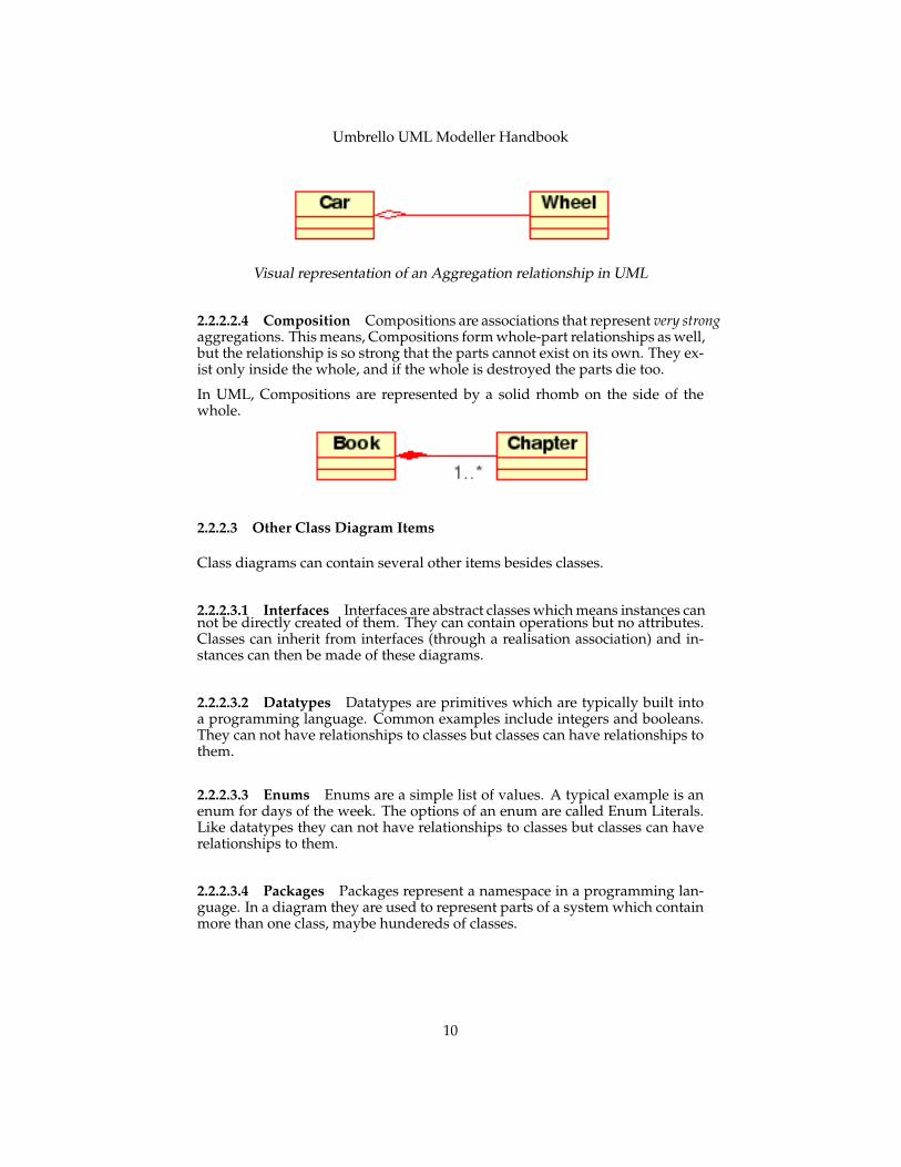
2.2.2.2.3 Aggregation Aggregations are a special type of associations in whichthe two participating classes don’t have an equal status, but make a ‘whole-part’ relationship. An Aggregation describes how the class that takes the roleof the whole, is composed (has) of other classes, which take the role of theparts. For Aggregations, the class acting as the whole always has a multiplicityof one.In UML, Aggregations are represented by an association that shows a rhombon the side of the whole.
9
Umbrello UML Modeller Handbook
Visual representation of an Aggregation relationship in UML
2.2.2.2.4 Composition Compositions are associations that represent very strongaggregations. This means, Compositions form whole-part relationships as well,but the relationship is so strong that the parts cannot exist on its own. They ex-ist only inside the whole, and if the whole is destroyed the parts die too.
In UML, Compositions are represented by a solid rhomb on the side of thewhole.
2.2.2.3 Other Class Diagram Items
Class diagrams can contain several other items besides classes.
2.2.2.3.1 Interfaces Interfaces are abstract classes which means instances cannot be directly created of them. They can contain operations but no attributes.Classes can inherit from interfaces (through a realisation association) and in-stances can then be made of these diagrams.
2.2.2.3.2 Datatypes Datatypes are primitives which are typically built intoa programming language. Common examples include integers and booleans.They can not have relationships to classes but classes can have relationships tothem.
2.2.2.3.3 Enums Enums are a simple list of values. A typical example is anenum for days of the week. The options of an enum are called Enum Literals.Like datatypes they can not have relationships to classes but classes can haverelationships to them.
2.2.2.3.4 Packages Packages represent a namespace in a programming lan-guage. In a diagram they are used to represent parts of a system which containmore than one class, maybe hundereds of classes.
10
Umbrello UML Modeller Handbook
2.2.3 Sequence Diagrams
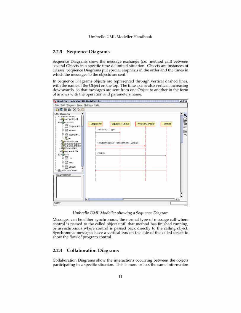
Sequence Diagrams show the message exchange (i.e. method call) betweenseveral Objects in a specific time-delimited situation. Objects are instances ofclasses. Sequence Diagrams put special emphasis in the order and the times inwhich the messages to the objects are sent.
In Sequence Diagrams objects are represented through vertical dashed lines,with the name of the Object on the top. The time axis is also vertical, increasingdownwards, so that messages are sent from one Object to another in the formof arrows with the operation and parameters name.
Umbrello UML Modeller showing a Sequence Diagram
Messages can be either synchronous, the normal type of message call wherecontrol is passed to the called object until that method has finished running,or asynchronous where control is passed back directly to the calling object.Synchronous messages have a vertical box on the side of the called object toshow the flow of program control.
2.2.4 Collaboration Diagrams
Collaboration Diagrams show the interactions occurring between the objectsparticipating in a specific situation. This is more or less the same information
11
Umbrello UML Modeller Handbook
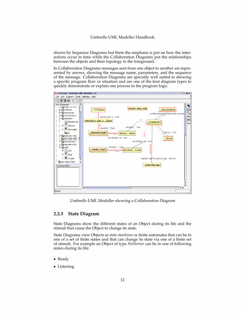
shown by Sequence Diagrams but there the emphasis is put on how the inter-actions occur in time while the Collaboration Diagrams put the relationshipsbetween the objects and their topology in the foreground.
In Collaboration Diagrams messages sent from one object to another are repre-sented by arrows, showing the message name, parameters, and the sequenceof the message. Collaboration Diagrams are specially well suited to showinga specific program flow or situation and are one of the best diagram types toquickly demonstrate or explain one process in the program logic.
Umbrello UML Modeller showing a Collaboration Diagram
2.2.5 State Diagram
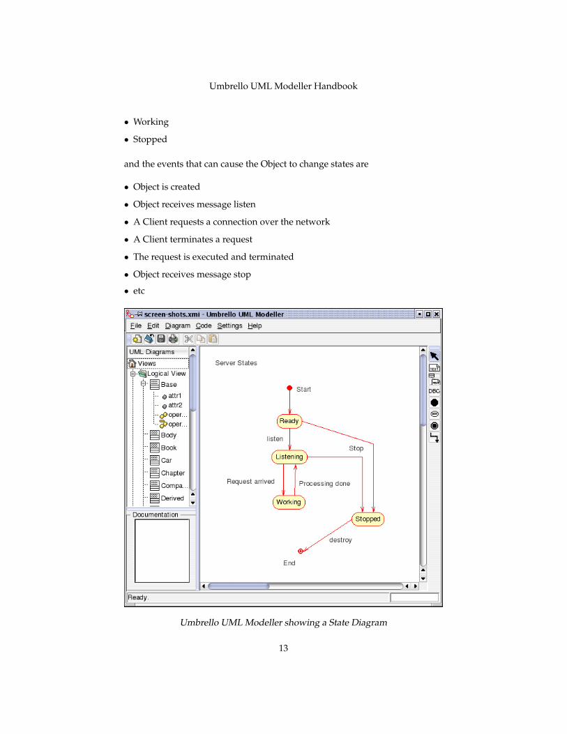
State Diagrams show the different states of an Object during its life and thestimuli that cause the Object to change its state.
State Diagrams view Objects as state machines or finite automates that can be inone of a set of finite states and that can change its state via one of a finite setof stimuli. For example an Object of type NetServer can be in one of followingstates during its life:
• Ready
• Listening
12
Umbrello UML Modeller Handbook
• Working
• Stopped
and the events that can cause the Object to change states are
• Object is created
• Object receives message listen
• A Client requests a connection over the network
• A Client terminates a request
• The request is executed and terminated
• Object receives message stop
• etc
Umbrello UML Modeller showing a State Diagram
13
Umbrello UML Modeller Handbook
2.2.5.1 State
States are the building block of State Diagrams. A State belongs to exactly oneclass and represents a summary of the values the attributes of a class can take.A UML State describes the internal state of an object of one particular class
Note that not every change in one of the attributes of an object should be repre-sented by a State but only those changes that can significantly affect the work-ings of the object
There are two special types of States: Start and End. They are special in thatthere is no event that can cause an Object to return to its Start state, in the sameway as there is no event that can possible take an Object out of its End stateonce it has reached it.
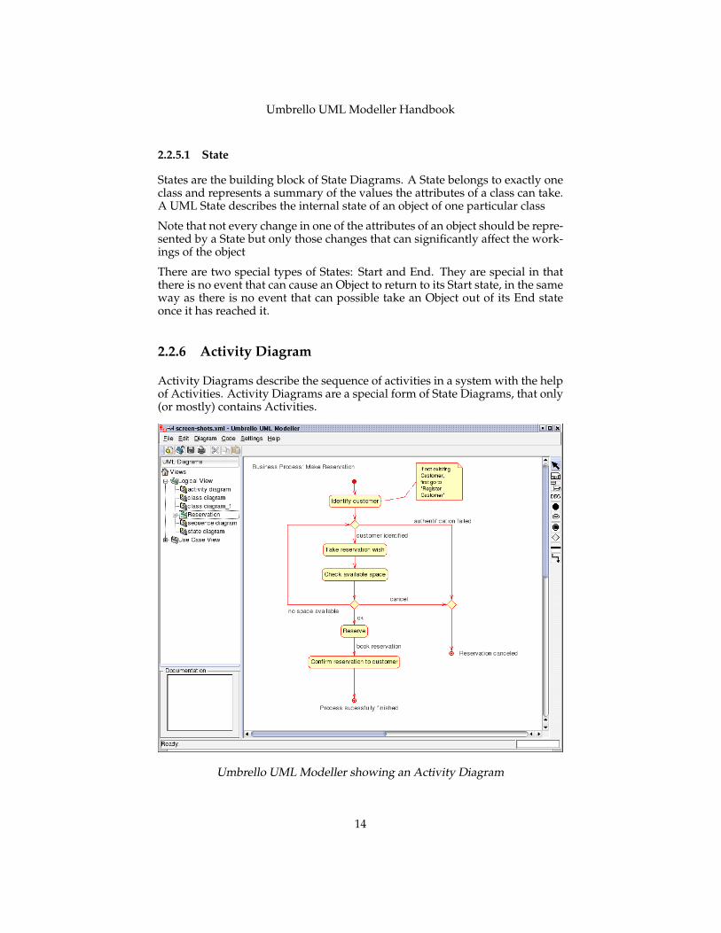
2.2.6 Activity Diagram
Activity Diagrams describe the sequence of activities in a system with the helpof Activities. Activity Diagrams are a special form of State Diagrams, that only(or mostly) contains Activities.
Umbrello UML Modeller showing an Activity Diagram
14
Umbrello UML Modeller Handbook
Activity Diagrams are similar to procedural Flux Diagrams, with the differencethat all Activities are clearly attached to Objects.
Activity Diagrams are always associated to a Class, an Operation or a Use Case.
Activity Diagrams support sequential as well as parallel Activities. Parallelexecution is represented via Fork/Wait icons, and for the Activities running inparallel, it is not important the order in which they are carried out (they can beexecuted at the same time or one after the other)
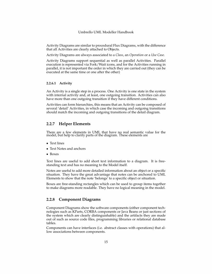
2.2.6.1 Activity
An Activity is a single step in a process. One Activity is one state in the systemwith internal activity and, at least, one outgoing transition. Activities can alsohave more than one outgoing transition if they have different conditions.
Activities can form hierarchies, this means that an Activity can be composed ofseveral ‘detail’ Activities, in which case the incoming and outgoing transitionsshould match the incoming and outgoing transitions of the detail diagram.
2.2.7 Helper Elements
There are a few elements in UML that have no real semantic value for themodel, but help to clarify parts of the diagram. These elements are
• Text lines
• Text Notes and anchors
• Boxes
Text lines are useful to add short text information to a diagram. It is free-standing text and has no meaning to the Model itself.
Notes are useful to add more detailed information about an object or a specificsituation. They have the great advantage that notes can be anchored to UMLElements to show that the note ‘belongs’ to a specific object or situation.
Boxes are free-standing rectangles which can be used to group items togetherto make diagrams more readable. They have no logical meaning in the model.
2.2.8 Component Diagrams
Component Diagrams show the software components (either component tech-nologies such as KParts, CORBA components or Java Beans or just sections ofthe system which are clearly distinguishable) and the artifacts they are madeout of such as source code files, programming libraries or relational databasetables.Components can have interfaces (i.e. abstract classes with operations) that al-low associations between components.
15
Umbrello UML Modeller Handbook
2.2.9 Deployment Diagrams
Deployment diagrams show the runtime component instances and their asso-ciations. They include Nodes which are physical resources, typically a singlecomputer. They also show interfaces and objects (class instances).
16
Umbrello UML Modeller Handbook
Chapter 3
Working with Umbrello UMLModeller
This chapter will introduce you to Umbrello UML Modeller’s user interfaceand will tell you all you need to know to start modelling. All actions in Um-brello UML Modeller are accessible via the menu and the toolbars, but Um-brello UML Modeller also makes extensive use of right mouse button contextmenus. You can right mouse button click on almost any element in UmbrelloUML Modeller’s work area or tree view to get a menu with the most usefulfunctions that can be applied to the particular element you are working on.Some users find this a little confusing at the beginning because they are moreused to working with the menu or tool bars, but once you get used to rightclicking it will greatly speed up your work.
3.1 User Interface
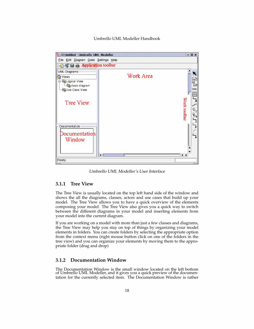
Umbrello UML Modeller’s main window is divided in three areas that willhelp you keep an overview of your entire system and access the different dia-grams quickly while working on your model.
These areas are called:
• Tree View
• Work Area
• Documentation Window
17
Umbrello UML Modeller Handbook
Umbrello UML Modeller’s User Interface
3.1.1 Tree View
The Tree View is usually located on the top left hand side of the window andshows the all the diagrams, classes, actors and use cases that build up yourmodel. The Tree View allows you to have a quick overview of the elementscomposing your model. The Tree View also gives you a quick way to switchbetween the different diagrams in your model and inserting elements fromyour model into the current diagram.
If you are working on a model with more than just a few classes and diagrams,the Tree View may help you stay on top of things by organizing your modelelements in folders. You can create folders by selecting the appropriate optionfrom the context menu (right mouse button click on one of the folders in thetree view) and you can organize your elements by moving them to the appro-priate folder (drag and drop)
3.1.2 Documentation Window
The Documentation Window is the small window located on the left bottomof Umbrello UML Modeller, and it gives you a quick preview of the documen-tation for the currently selected item. The Documentation Window is rather
18
Umbrello UML Modeller Handbook
small because it is intended to allow you just a quick pick into the element’sdocumentation while taking as little screen space as possible. If you need toview the documentation in more detail you can always open the item’s prop-erties.
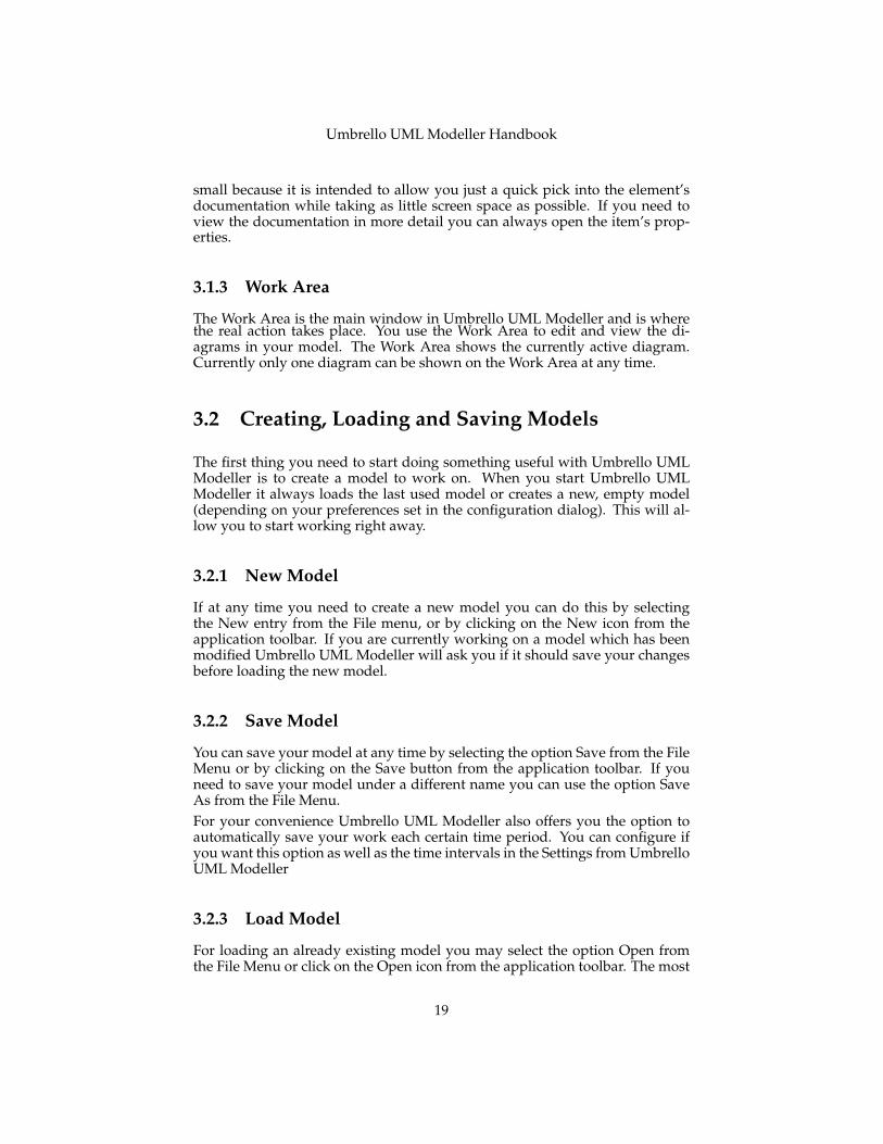
3.1.3 Work Area
The Work Area is the main window in Umbrello UML Modeller and is wherethe real action takes place. You use the Work Area to edit and view the di-agrams in your model. The Work Area shows the currently active diagram.Currently only one diagram can be shown on the Work Area at any time.
3.2 Creating, Loading and Saving Models
The first thing you need to start doing something useful with Umbrello UMLModeller is to create a model to work on. When you start Umbrello UMLModeller it always loads the last used model or creates a new, empty model(depending on your preferences set in the configuration dialog). This will al-low you to start working right away.
3.2.1 New Model
If at any time you need to create a new model you can do this by selectingthe New entry from the File menu, or by clicking on the New icon from theapplication toolbar. If you are currently working on a model which has beenmodified Umbrello UML Modeller will ask you if it should save your changesbefore loading the new model.
3.2.2 Save Model
You can save your model at any time by selecting the option Save from the FileMenu or by clicking on the Save button from the application toolbar. If youneed to save your model under a different name you can use the option SaveAs from the File Menu.For your convenience Umbrello UML Modeller also offers you the option toautomatically save your work each certain time period. You can configure ifyou want this option as well as the time intervals in the Settings from UmbrelloUML Modeller
3.2.3 Load Model
For loading an already existing model you may select the option Open fromthe File Menu or click on the Open icon from the application toolbar. The most
19

Umbrello UML Modeller Handbook
recently used models are also available under the submenu Open Recent in theFile Menu to speed up access to your most frequently used models.
Umbrello UML Modeller can only work on one model at a time, so if you askthe program to load a model for you and your current model has been modifiedsince the last time you save it, Umbrello UML Modeller will ask you whetheryour changes should be saved to prevent any loss of work. You can start twoor more instances of Umbrello UML Modeller at any one time, you can alsocopy and paste between instances.
3.3 Editing Models
In Umbrello UML Modeller, there are basically two ways for editing the ele-ments in your model.
• Edit model elements directly through the Tree View
• Edit model elements through a Diagram
Using the context menu of the different items in the Tree View you are able toadd, remove, and modify almost all the elements in your model. Right clickingon the folders in the Tree View will give you options for creating the differenttypes of diagrams as well as, depending on whether the folder is a Use CaseView or a Logical View, Actors, Use Cases, Classes, etc.
Once you have added elements to your model you can also edit an element byaccessing its properties dialog, which you find by selecting the option Propertiesfrom the context menu shown when right clicking on the items in the Tree View.
You can also edit your model by creating or modifying elements through dia-grams. More details on how to do this are given in the following sections.
3.4 Adding and Removing Diagrams
Your UML model consists of a set of UML elements and associations betweenthem. However you cannot see the model directly, you use Diagrams to look atit.
3.4.1 Creating Diagrams
To create a new diagram in your model simply select the diagram type youneed from the New submenu in the Diagram menu and give a name to it. Thediagram will be created and made active, and you will immediately see it inthe tree view.Remember that Umbrello UML Modeller makes extensive use of context menus:you can also right mouse button click on a folder in the Tree View and select the
20
Umbrello UML Modeller Handbook
appropriate diagram type from the New submenu in the context menu. Notethat you can create Use Case Diagrams only in Use Case View folders, and theother types of diagram can only be created in the Logical View folders.
3.4.2 Removing Diagrams
Should you need to remove a diagram from your model, you can do this bymaking it active and selecting Delete from the Diagram Menu. You can alsoachieve this by selecting Delete from the diagrams context menu in the TreeViewSince deleting a diagram is something serious that could cause loss of work ifdone by accident, Umbrello UML Modeller will ask you to confirm the deleteoperation before actually removing the Diagram. Once a diagram has beendeleted and the file has been saved there is no way to undo this action.
3.4.3 Renaming Diagrams
If you want to change the name of an existing diagram you can easily do thisby selecting the Rename option from its right mouse button menu in the TreeView.Another way to rename a diagram is to do this via its properties dialog, whichyou obtain by selecting Properties from its Context Menu or by double clickingon it in the Tree View.
3.5 Editing Diagrams
When working on a diagram, Umbrello UML Modeller will try to guide youby applying some simple rules as to which elements are valid in the differenttypes of diagrams, as well as the relationships that can exist between them. Ifyou are an UML expert you will probably not even notice it, but this will helpUML novices create standard-conformant diagrams.
Once you have created your diagrams it is time to start editing them. Hereyou should notice the (for beginners subtle) difference between editing yourdiagram, and editing the model. As you already know, Diagrams are views ofyour model. For example, if you create a class by editing a Class Diagram, youare really editing both, your Diagram and your model. If you change the coloror other display options of a Class in your Class Diagram, you are only editingthe Diagram, but nothing is changed in your model.
3.5.1 Insert Elements
One of the first things you will do when editing a new diagram is to insertelements into them (Classes, Actors, Use Cases, etc.) There is basically twoways of doing this:
21
Umbrello UML Modeller Handbook
• Dragging existing elements in your model from the Tree View
• Creating new elements in your model and adding them to your diagram atthe same time, by using one of the edit Tools in the Work Toolbar
To insert elements that already exist in your model, just drag them from theTree View and drop them where you want them to be in your diagram. Youcan always move elements around in your Diagram using the Select Tool
The second way of adding elements to your diagram is by using the WorkToolbar’s edit tools (note that this will also add the elements to your model).
The Work Toolbar was by default located on the far right of the applicationwindow, Umbrello UML Modeller 1.2 has moved this to the top of the window.You can dock it into other edge or have it floating around if you prefer. Thetools available on this toolbar (the buttons you see on it) change depending onthe type of diagram you are currently working on. The button for the currentlyselected tool is activated in the toolbar. You can switch to the select tool bypressing the Esc key.
When you have selected an edit tool from the Work Toolbar (for example, thetool to insert classes) the mouse pointer changes to a cross, and you can insertthe elements in your model by single clicking in your diagram. Note that el-ements in UML must have a Unique Name. So that if you have a class in onediagram whose name is ‘ClassA’ and then you use the insert Class tool to inserta class into another diagram you cannot name this new class ‘ClassA’ as well.If these two are supposed to be two different elements, you have to give them aunique name. If you are trying to add the same element to your diagram, thenthe Insert Class is not the right tool for that. You should drag and drop theclass from the Tree View instead.
3.5.2 Deleting Elements
You can delete any element by selecting the option Delete from its contextmenu.Again, there is a big difference between removing an object from a diagram,and deleting an object from your model: If you delete an object from within adiagram, you are only removing the object from that particular diagram: theelement will still be part of your model and if there are other diagrams usingthe same element they will not suffer any change. If, on the other hand, youdelete the element from the Tree View, you are actually deleting the elementfrom your model. Since the element no longer exist in your model, it will beautomatically removed from all the diagrams it appears in.
3.5.3 Editing Elements
You can edit most of the UML elements in your model and diagrams by open-ing its Properties dialog and selecting the appropriate options. To edit the
22
Umbrello UML Modeller Handbook
properties of an object, select Properties from its context menu (right mousebutton click). Each element has a dialog consisting of several pages where youcan configure the options corresponding to that element. For some elements,like actors you can only set a couple of options, like the object name and docu-mentation, while for other elements, like classes, you can edit its attributes andoperations, select what you want to be shown in the diagram (whole operationsignature or just operation names, etc) and even the colors you want to use forthe line and fill of the class’ representation on the diagram.
For most UML elements you can also open the properties dialog by doubleclicking on it if you are using the selection tool (arrow). The exception to this isAssociations, in which case a double click creates an anchor point. For associa-tions you need to use the right mouse button context menu to get the propertiesdialog.
Note that you can also select the properties option from the context menu ofthe elements in the Tree View. This allows you to also edit the properties forthe diagrams, like setting whether the grid should be shown or not.
3.5.4 Editing Classes
Even though editing the properties of all objects was already covered in theprevious section, classes deserve a special section because they are a bit morecomplicated and have more options than most of the other UML elements.
In the properties dialog for a class you can set everything, from the color it usesto the operations and attributes it has.
3.5.4.1 Class General Settings
The General Settings page of the properties dialog is self-explanatory. Hereyou can change the class’ name, visibility, documentation, etc. This page isalways available.
3.5.4.2 Class Attribute Settings
In the Attributes Settings page you can add, edit, or delete attributes (variables)of the class. You can move attributes up and down the list by pressing thearrow button on the side. This page is always available.
3.5.4.3 Class Operations Settings
Similar to the Attribute Settings Page, in the Operation Settings Page you canadd, edit, or remove operations for your class. When adding or editing anoperation, you enter the basic data in the Operation Properties dialog. If youwant to add parameters to your operation you need to click the New Parameterbutton, which will show the Parameter Properties dialog. This page is alwaysavailable
23
Umbrello UML Modeller Handbook
3.5.4.4 Class Template Settings
This page allows you to add class templates which are unspecified classes ordatatypes. In Java 1.5 these will be called Generics.
3.5.4.5 Class Associations Page
The Class Associations page shows all the associations of this class in the cur-rent diagram. Double clicking on an association shows its properties, and de-pending on the type of association you may modify some parameters here suchas setting multiplicity and Role name. If the association does not allow suchoptions be be modified, the Association Properties dialog is read-only and youcan only modify the documentation associated with this association.
This page is only available if you open the Class Properties from within a dia-gram. If you select the class properties from the context menu in the Tree Viewthis page is not available.
3.5.4.6 Class Display Page
In the Display Options page, you can set what is to be shown in the diagram.A class can be shown as only one rectangle with the class name in it (useful ifyou have many classes in your diagram, or are for the moment not interestedin the details of each class) or as complete as showing packages, stereotypes,and attributes and operations with full signature and visibility
Depending on the amount of information you want to see you can select thecorresponding options in this page. The changes you make here are only dis-play options for the diagram. This means that ‘hiding’ a class’ operations onlymakes them not to be shown in the diagram, but the operation are still there aspart of your model. This option is only available if you select the class proper-ties from within a Diagram. If you open the class properties from the Tree Viewthis page is missing since such Display Options do not make sense in that case
3.5.4.7 Class Color Page
In the Widget Color page you can configure the colors you want for the lineand the fill of the widget. This option obviously makes sense only for classesdisplayed in diagrams, and is missing if you open the class’ properties dialogfrom the Tree View.
3.5.5 Associations
Associations relate two UML objects to each other. Normally associations aredefined between two classes, but some types of associations can also existsbetween use cases and actors.
24
Umbrello UML Modeller Handbook
To create an association select the appropriate tool from the Work Toolbar (genericAssociation, Generalization, Aggregation, etc.) and single click on the first el-ement participating in the association and then single click on the second itemparticipating. Note that those are two clicks, one on each on the objects partic-ipating in the association, it is not a drag from one object to the other.
If you try to use an association in a way against the UML specification Um-brello UML Modeller will refuse to create the association and you will get anerror message. This would be the case if, for example, a Generalization existsfrom class A to class B and then you try to create another Generalization fromClass B to class ARight clicking on an association will show a context menu with the actions youcan apply on it. If you need to delete an association simply select the Deleteoption from this context menu. You can also select the Properties option and,depending on the association type edit attributes such as roles and multiplicity.
3.5.5.1 Anchor Points
Associations are drawn, by default, as a straight line connecting the two objectsin the diagram.
You can add anchor points to bend an association by double clicking somewhere along the association line. This will insert an anchor point (displayed asa blue point when the association line is selected) which you can move aroundto give shape to the association
If you need to remove an anchor point, double click on it again to remove it
Note that the only way to edit the properties of an association is through thecontext menu. If you try to double click on it as with other UML objects, thiswill only insert an anchor point.
3.5.6 Notes, Text and Boxes
Notes, Lines Of Text and Boxes are elements that can be present in any typeof diagram and have no real semantic value, but are very helpful to add extracomments or explanations that can make your diagram easier to understand.
To add a Note or a Line Of Text, select the corresponding tool from the WorkToolbar and single click on the diagram where you want to put your comment.You can edit the text by opening the element through its context menu or in thecase of notes by double clicking on them as well.
3.5.6.1 Anchors
Anchors are used to link a text note and another UML Element together. Forexample, you normally use a text note to explain or make some comment abouta class or a particular association, in which case you can use the anchor to makeit clear that the note ‘belongs’ to that particular element.
25

Umbrello UML Modeller Handbook
To add an anchor between a note and another UML element, use the anchortool from the work toolbar. You first need to click on the note and then click onthe UML element you want the note to be linked to.
26
Umbrello UML Modeller Handbook
Chapter 4
Code Import and CodeGeneration
Umbrello UML Modeller is a UML modelling tool, and as such its main pur-pose is to help you in the analysis and design of your systems. However, tomake the transition between your design and your implementation, UmbrelloUML Modeller allows you to generate source code in different programminglanguages to get you started. Also, if you want to start using UML in an alreadystarted C++ project, Umbrello UML Modeller can help you create a model ofyour system from the source code by analysing your source code and import-ing the classes found in it.
4.1 Code Generation
Umbrello UML Modeller can generate source code for various programminglanguages based on your UML Model to help you get started with the im-plementation of your project. The code generated consists of the class dec-larations, with their methods and attributes so you can ‘fill in the blanks’ byproviding the functionality of your classes’ operations.
Umbrello UML Modeller 1.2 comes with code generation support for Action-Script, Ada, C++, CORBA IDL, JavaTM, JavaScript, PHP, Perl, Python, SQL andXMLSchema.
4.1.1 Generating Code
In order to generate code with Umbrello UML Modeller, you first need to createor load a Model containing at least one class. When you are ready to start writ-ing some code, select the Code Generation Wizard entry from the Code menuto start a wizard which will guide you trough the code generation process.
27
Umbrello UML Modeller Handbook
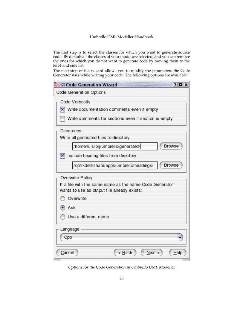
The first step is to select the classes for which you want to generate sourcecode. By default all the classes of your model are selected, and you can removethe ones for which you do not want to generate code by moving them to theleft-hand side list.The next step of the wizard allows you to modify the parameters the CodeGenerator uses while writing your code. The following options are available:
Options for the Code Generation in Umbrello UML Modeller
28
Umbrello UML Modeller Handbook
4.1.1.1 Generation Options
4.1.1.1.1 Code Verbosity The option Write documentation comments evenif empty instructs the Code Generator to write comments of the /** blah */style even if the comment blocks are empty. If you added documentation toyour classes, methods or attributes in your Model, the Code Generator willwrite these comments as Doxygen documentation regardless of what you sethere, but if you select this option Umbrello UML Modeller will write commentblocks for all classes, methods and attributes even if there is no documentationin the Model, in which case you should document your classes later directly inthe source code.Write comments for sections even if section is empty causes Umbrello UMLModeller to write comments in the source code to delimit the different sectionsof a class. For example ‘public methods’ or ‘Attributes’ before the correspond-ing sections. If you select this option Umbrello UML Modeller will write com-ments for all sections of the class even if the section is empty. For example, itwould write a comment saying ‘protected methods’ even if there are no pro-tected methods in your class.
4.1.1.1.2 Folders Write all generated files to folder. Here you should se-lect the folder where you want Umbrello UML Modeller to put the generatedsources.The Include heading files from folder option allows you to insert a headingat the beginning of each generated file. Heading files can contain copyrightor licensing information and contain variables that are evaluated at generationtime. You can take a look at the template heading files shipped with UmbrelloUML Modeller to see how to use this variables for replacing your name or thecurrent date at generation time.
4.1.1.1.3 Overwrite Policy This option tells Umbrello UML Modeller whatto do if the file it wants to create already exists in the destination folder. Um-brello UML Modeller cannot modify existing source files, so you have to choosebetween overwriting the existing file, skipping the generation of that particu-lar file or letting Umbrello UML Modeller choose a different file name. If youchoose the option to use a different name, Umbrello UML Modeller will add asuffix to the file name.
4.1.1.1.4 Language Umbrello UML Modeller will by default generate codein the language you have selected as Active Language, but with the Code Gen-eration Wizard you have the option to change this to another language.
4.1.1.2 Generation Wizard Generation
The third and last step of the wizard shows the status of the Code Generationprocess. You need only to click on the Generate button to get your classeswritten for you.
29
Umbrello UML Modeller Handbook
Note that the Options you select during the Code Generation Wizard are onlyvalid for the current generation. The next time you run the wizard you willneed to re-select all the options (your headings folder, overwrite policy, andso on). You can set the defaults used by Umbrello UML Modeller in the CodeGeneration section of the Umbrello UML Modeller settings, available at Set-tings→ Configure Umbrello UML Modeller...
If you have set your Code Generation options to the right settings and wantto generate some code right away without going through the wizard, you canselect the entire Generate All Code from the Code menu. This will generatecode for all the classes in your Model using the current settings (includingOutput Folder and Overwrite Policy, so use with care).
4.2 Code Import
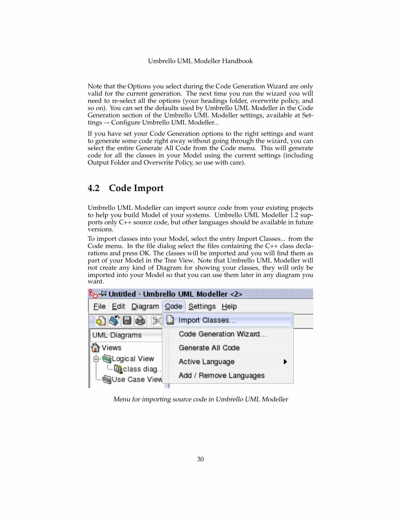
Umbrello UML Modeller can import source code from your existing projectsto help you build Model of your systems. Umbrello UML Modeller 1.2 sup-ports only C++ source code, but other languages should be available in futureversions.To import classes into your Model, select the entry Import Classes... from theCode menu. In the file dialog select the files containing the C++ class decla-rations and press OK. The classes will be imported and you will find them aspart of your Model in the Tree View. Note that Umbrello UML Modeller willnot create any kind of Diagram for showing your classes, they will only beimported into your Model so that you can use them later in any diagram youwant.
Menu for importing source code in Umbrello UML Modeller
30
Umbrello UML Modeller Handbook
Chapter 5
Other Features
5.1 Other Umbrello UML Modeller Features
This chapter will briefly explain some other features Umbrello UML Modelleroffers you.
5.1.1 Copying objects as PNG images
Apart from offering you the normal copy, cut and paste functionality that youwould expect to copy objects between different diagrams, Umbrello UML Mod-eller can copy the objects as PNG pictures so that you can insert them into anyother type of document. You do not need to do anything special to use this fea-ture, just select an object from a diagram (Class, Actor, etc.) and copy it (Ctrl-C,or using the menu), then open a KWord document (or any program into whichyou can paste images) and select Paste. This is a great feature to export partsof your diagram as simple pictures.
5.1.2 Exporting to an Image
You can also export a complete diagram as an image. The only thing you needto do is select the diagram you want to export, and then the option Export asPicture... from the Diagram menu.
5.1.3 Printing
Umbrello UML Modeller allows you to print individual diagrams. Press thePrint button on the application toolbar or selecting the Print option from theFile menu will give you a standard KDE Print dialog from where you can printyour diagrams.
31
Umbrello UML Modeller Handbook
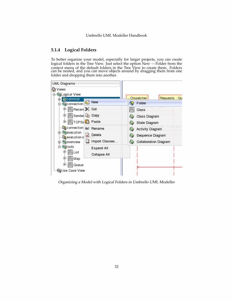
5.1.4 Logical Folders
To better organize your model, especially for larger projects, you can createlogical folders in the Tree View. Just select the option New→ Folder from thecontext menu of the default folders in the Tree View to create them. Folderscan be nested, and you can move objects around by dragging them from onefolder and dropping them into another.
Organizing a Model with Logical Folders in Umbrello UML Modeller
32
Umbrello UML Modeller Handbook
Chapter 6
Authors and History
This project was started by Paul Hensgen as one of his University projects. Theoriginal name of the application was UML Modeller. Paul did all the develop-ment until the end of 2001 when the program reached version 1.0.
Version 1.0 already offered a lot of functionality, but after the project had beenreviewed at Paul’s University, other developers could join and they startedmaking valuable contributions to UML Modeller, like switching from a binaryfile format to an XMLTM file, support for more types of UML Diagrams, CodeGeneration and Code Import just to name a few.
Paul had to retire from the development team in Summer 2002 but, as Free andOpen Source Software, the program continues to improve and evolve and isbeing maintained by a group of developers from different parts of the world. InSeptember 2002 the project changed its name from UML Modeller, to UmbrelloUML Modeller. There are several reasons for the change of names, the mostimportant ones being that just ‘uml’ — as it was commonly known — was amuch too generic name and caused problems with some distributions. Theother important reason is that the developers think Umbrello is a much coolername.The development of Umbrello UML Modeller as well as discussions as to wherethe program should head for future versions is open and takes place over theInternet. If you would like to contribute to the project, please do not hesitate tocontact the developers. There are many ways in which you can help UmbrelloUML Modeller:
• Reporting bugs or improvements suggestions
• Fixing bugs or adding features
• Writing good documentation or translating it to other languages
• And of course...coding with us!
33

Umbrello UML Modeller Handbook
As you see, there are many ways in which you can contribute. All of them arevery important and everyone is welcome to participate.
The Umbrello UML Modeller developers can be reached at [email protected].
34

Umbrello UML Modeller Handbook
Chapter 7
Copyright
Copyright 2001, Paul Hensgen
Copyright 2002, 2003 The Umbrello UML Modeller Authors. See http://uml.sf.net/-developers.php for more information
This documentation is licensed under the terms of the GNU Free Documenta-tion License.This program is licensed under the terms of the GNU General Public License.
35