UM1960 User manual - st.com€¦ · User manual Sample wM-Bus 2013 application layer implementation...
27
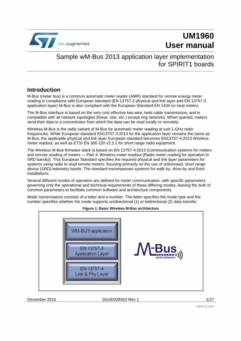
December 2015 DocID028453 Rev 1 1/27 www.st.com UM1960 User manual Sample wM-Bus 2013 application layer implementation for SPIRIT1 boards Introduction M-Bus (meter bus) is a common automatic meter reader (AMR) standard for remote energy meter reading in compliance with European standard (EN 13757-2 physical and link layer and EN 13757-3 application layer) M-Bus is also compliant with the European Standard EN 1434 on heat meters. The M-Bus interface is based on the very cost effective two-wire, twist cable transmission, and is compatible with all network topologies (linear, star, etc.) except ring networks. When queried, meters send their data to a concentrator from which the data can be read locally or remotely. Wireless M-Bus is the radio variant of M-Bus for automatic meter reading at sub-1-GHz radio frequencies. While European standard EN13757-3:2013 for the application layer remains the same as M-Bus, the applicable physical and link layer European standard becomes EN13757-4:2013 Wireless meter readout, as well as ETSI EN 300 220 v2.3.1 for short range radio equipment. The Wireless M-Bus firmware stack is based on EN 13757-4:2013 (Communication systems for meters and remote reading of meters — Part 4: Wireless meter readout (Radio meter reading for operation in SRD bands)). This European Standard specifies the required physical and link layer parameters for systems using radio to read remote meters, focusing primarily on the use of unlicensed, short range device (SRD) telemetry bands. The standard encompasses systems for walk-by, drive-by and fixed installations. Several different modes of operation are defined for meter communication, with specific parameters governing only the operational and technical requirements of these differing modes, leaving the bulk of common parameters to facilitate common software and architecture components. Mode nomenclature consists of a letter and a number. The letter specifies the mode type and the number specifies whether the mode supports unidirectional (1) or bidirectional (2) data transfer. Figure 1: Basic Wireless M-Bus architecture
Transcript of UM1960 User manual - st.com€¦ · User manual Sample wM-Bus 2013 application layer implementation...
December 2015 DocID028453 Rev 1 1/27
www.st.com
UM1960 User manual
Sample wM-Bus 2013 application layer implementation for SPIRIT1 boards
Introduction M-Bus (meter bus) is a common automatic meter reader (AMR) standard for remote energy meter reading in compliance with European standard (EN 13757-2 physical and link layer and EN 13757-3 application layer) M-Bus is also compliant with the European Standard EN 1434 on heat meters.
The M-Bus interface is based on the very cost effective two-wire, twist cable transmission, and is compatible with all network topologies (linear, star, etc.) except ring networks. When queried, meters send their data to a concentrator from which the data can be read locally or remotely.
Wireless M-Bus is the radio variant of M-Bus for automatic meter reading at sub-1-GHz radio frequencies. While European standard EN13757-3:2013 for the application layer remains the same as M-Bus, the applicable physical and link layer European standard becomes EN13757-4:2013 Wireless meter readout, as well as ETSI EN 300 220 v2.3.1 for short range radio equipment.
The Wireless M-Bus firmware stack is based on EN 13757-4:2013 (Communication systems for meters and remote reading of meters — Part 4: Wireless meter readout (Radio meter reading for operation in SRD bands)). This European Standard specifies the required physical and link layer parameters for systems using radio to read remote meters, focusing primarily on the use of unlicensed, short range device (SRD) telemetry bands. The standard encompasses systems for walk-by, drive-by and fixed installations.
Several different modes of operation are defined for meter communication, with specific parameters governing only the operational and technical requirements of these differing modes, leaving the bulk of common parameters to facilitate common software and architecture components.
Mode nomenclature consists of a letter and a number. The letter specifies the mode type and the number specifies whether the mode supports unidirectional (1) or bidirectional (2) data transfer.
Figure 1: Basic Wireless M-Bus architecture
Definitions, acronyms and abbreviations UM1960
2/27 DocID028453 Rev 1
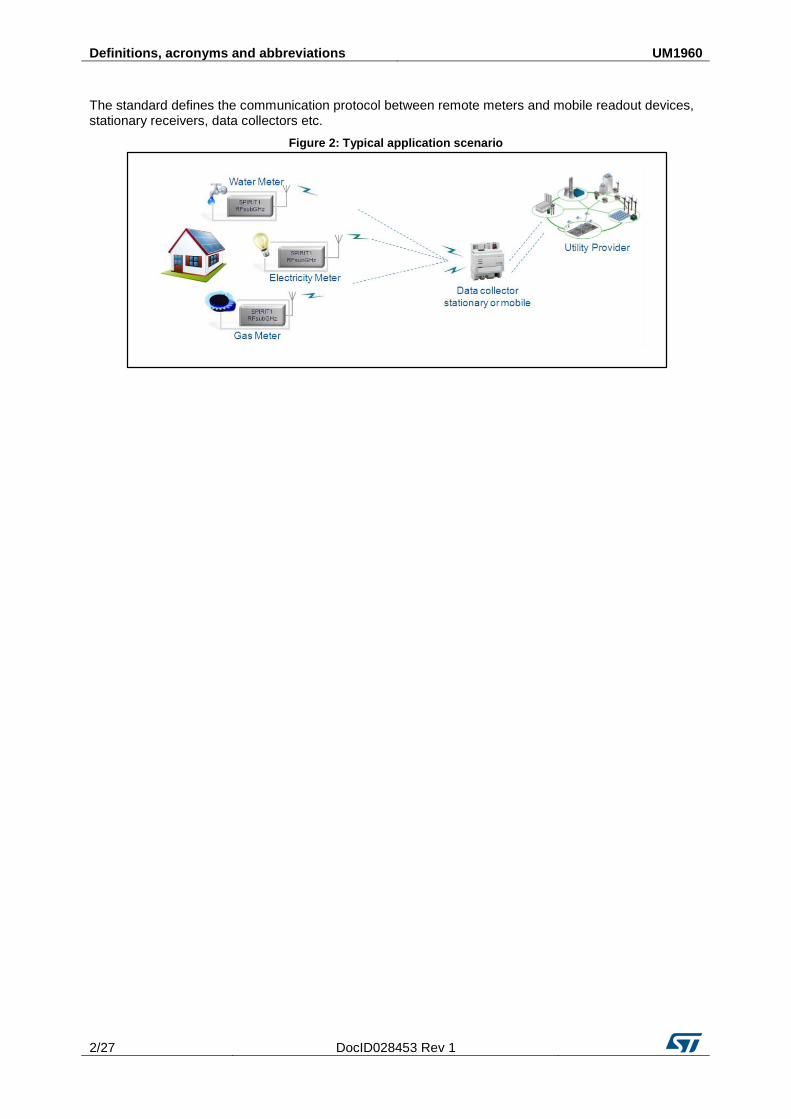
The standard defines the communication protocol between remote meters and mobile readout devices, stationary receivers, data collectors etc.
Figure 2: Typical application scenario
UM1960 Contents
DocID028453 Rev 1 3/27
Contents
1 Definitions, acronyms and abbreviations ...................................... 6
2 Hardware platform ........................................................................... 7
2.1 SPIRIT1 ............................................................................................ 7
2.1.1 SPIRIT1 function: ............................................................................... 7
2.2 ST’s ultra-low power EnergyLite™ MCU family ................................. 8
2.2.1 STM32L function: ............................................................................... 8
3 wM-Bus software package description .......................................... 9
3.1 Overview ........................................................................................... 9
3.2 Architecture ....................................................................................... 9
3.2.1 Hardware .......................................................................................... 10
3.2.2 Driver ................................................................................................ 10
3.2.3 BSP................................................................................................... 10
3.2.4 Middleware library ............................................................................ 10
3.2.5 Application layer ............................................................................... 10
3.3 Folder structure ............................................................................... 11
3.4 APIs ................................................................................................ 11
3.5 Software setup ................................................................................ 11
4 Application Example ..................................................................... 12
4.1 wM-Bus Workspace ........................................................................ 12
4.1.1 wM-Bus workspace folder structure ................................................. 12
4.1.2 wM-Bus application demonstration: ................................................. 12
4.2 PC application demonstration ......................................................... 14
5 Hardware description .................................................................... 16
5.1 STEVAL-IKR002Vx (main board) .................................................... 16
5.1.1 Push buttons and joystick ................................................................. 17
5.1.2 JTAG connector ................................................................................ 17
5.1.3 LEDs ................................................................................................. 17
5.2 STEVAL-IKR002Vx (RF module) .................................................... 17
5.2.1 Boost mode ...................................................................................... 18
5.3 Hardware setup ............................................................................... 19
5.3.1 Hardware equipment ........................................................................ 19
5.3.2 Setting up the board ......................................................................... 19
5.4 Running sample applications on the STEVAL-IKR002Vx board ..... 19

Contents UM1960
4/27 DocID028453 Rev 1
6 Using the demo board with PC application ................................. 21
6.1 wM-Bus Demo Suite system requirements ..................................... 21
6.2 wM-Bus Demo Suite installation ...................................................... 21
7 References ..................................................................................... 25
8 Revision history ............................................................................ 26

UM1960 List of figures
DocID028453 Rev 1 5/27
List of figures
Figure 1: Basic Wireless M-Bus architecture .............................................................................................. 1 Figure 2: Typical application scenario ........................................................................................................ 2 Figure 3: Application layers ........................................................................................................................ 7 Figure 4: wM-Bus Firmware Architecture ................................................................................................... 9 Figure 5: wM-Bus 2013 package folder structure ..................................................................................... 11 Figure 6: wM-Bus workspace folder structure .......................................................................................... 12 Figure 7: wM-Bus workspace overview .................................................................................................... 13 Figure 8: Packet flow ................................................................................................................................ 14 Figure 9: wM-Bus Demo Suite Interface ................................................................................................... 15 Figure 10: STEVAL- IKR002Vx main board ............................................................................................. 16 Figure 11: STEVAL-IKR002Vx board (RF module) .................................................................................. 18 Figure 12: STEVAL-IKR002Vx (RF module) boost mode configuration ................................................... 19 Figure 13: User firmware settings ............................................................................................................. 20 Figure 14: wM-Bus Demo Suite installation screen 1 ............................................................................... 21 Figure 15: wM-Bus Demo Suite installation screen 2 ............................................................................... 22 Figure 16: wM-Bus Demo Suite installation screen 3 ............................................................................... 23 Figure 17: wM-Bus Demo Suite installation screen 4 ............................................................................... 24

Definitions, acronyms and abbreviations UM1960
6/27 DocID028453 Rev 1
1 Definitions, acronyms and abbreviations Table 1: Acronyms and abbreviations
Acronym Description
AMR Automatic Meter Reading
EEPROM Electrically Erasable Programmable Read Only Memory
GHz Giga Hertz
GUI Graphical User Interface
LED Light Emitting Diode
MCU Microcontroller Unit
PC Personal Computer
RF Radio Frequency communication
SPI Serial Peripheral Interface
USB Universal Serial Bus
wM-Bus Wireless Metering Bus
WSN Wireless Sensors Network
UM1960 Hardware platform
DocID028453 Rev 1 7/27
2 Hardware platform
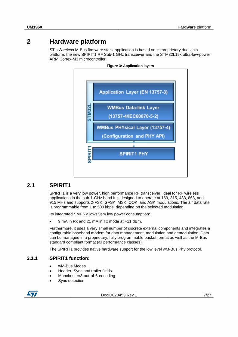
ST’s Wireless M-Bus firmware stack application is based on its proprietary dual chip platform: the new SPIRIT1 RF Sub-1 GHz transceiver and the STM32L15x ultra-low-power ARM Cortex-M3 microcontroller.
Figure 3: Application layers
2.1 SPIRIT1
SPIRIT1 is a very low power, high performance RF transceiver, ideal for RF wireless applications in the sub-1-GHz band It is designed to operate at 169, 315, 433, 868, and 915 MHz and supports 2-FSK, GFSK, MSK, OOK, and ASK modulations. The air data rate is programmable from 1 to 500 kbps, depending on the selected modulation.
Its integrated SMPS allows very low power consumption:
9 mA in Rx and 21 mA in Tx mode at +11 dBm.
Furthermore, it uses a very small number of discrete external components and integrates a configurable baseband modem for data management, modulation and demodulation. Data can be managed in a proprietary, fully programmable packet format as well as the M-Bus standard compliant format (all performance classes).
The SPIRIT1 provides native hardware support for the low level wM-Bus Phy protocol.
2.1.1 SPIRIT1 function:
wM-Bus Modes
Header, Sync and trailer fields
Manchester/3-out-of-6-encoding
Sync detection

Hardware platform UM1960
8/27 DocID028453 Rev 1
2.2 ST’s ultra-low power EnergyLite™ MCU family
Gas, water and heat meters with wM-Bus technologies are usually battery powered devices that nned to be highly efficient to preserve battery life.
The 8-bit (STM8L) and 32-bit (STM32L) EnergyLite™ family of MCUs combines high performance and ultra-low power, offering specific features for ultra-low power applications such as advanced ultra-low power modes and optimized dynamic run consumption, as well as special safety features.
The ultra-low-power EnergyLite platform, based on STMicroelectronics’ 130 nm ultra-low-leakage process technology, provides a common technology, design and peripheral framework across the product range.
The ARM® Cortex™-M3-based STM32L1 series extends the ultra-low power concept without compromising performance, offering a wide assortment of features, memory sizes and packages. The range covers 32 to 384 Kbytes Flash memory (with up to 48 Kbytes of RAM and 12 Kbytes of true embedded EEPROM) and 48 to 144 pins.
This innovative architecture, with voltage scaling and an ultra-low-power MSI oscillator, gives your design more performance for a very low power budget. The generous suite of embedded peripherals, including USB, LCD interface, OpAmp, comparator, ADC with fast on/off mode, DAC, capacitive touch and AES renders the STM32L1 series an expandable platform able to fit all your requirements.
2.2.1 STM32L function:
wM-Bus application layer
wireless M-Bus application layer partially implementing EN13757-3.
wM-Bus link layer
MAC packet and CRC handling
encryption/ decryption initiate/read.
wM-Bus Phy
init Phy for wM-Bus
interrupt services

UM1960 wM-Bus software package description
DocID028453 Rev 1 9/27
3 wM-Bus software package description
3.1 Overview
The Wireless M-Bus software package includes:
supporting documentation:
wireless M-Bus firmware and application user manual (this document)
wireless M-Bus stack application note
the GUI help file
firmware:
wireless 2013 library
SPIRIT1_Libraries
STM32L1xx_StdPeriph_Lib
STM32_USB-FS-Device_Driver
application files
PC-application:
the PC-GUI set-up
The software described herein can be used to develop the following applications:
automatic meter reading
gas meter reading
water meter reading
electricity meter reading
heat meter reading
3.2 Architecture
Figure 4: wM-Bus Firmware Architecture

wM-Bus software package description UM1960
10/27 DocID028453 Rev 1
There are five layers in the architecture. The wM-Bus link and the wM-Bus Phy layers are associated with specification EN 13757-4, while the wM-Bus application layer adheres to wM-Bus specification EN 13757-3.
3.2.1 Hardware
This layer reveals the supported microcontroller and the transceiver.
3.2.2 Driver
This layer provides the standard library function to operate the STM32 microcontroller as well as the driver library for the SPIRIT1 transceiver.
3.2.3 BSP
Software support for all of the peripherals (except for the MCU) on the STEVAL-IKR002Vx is included in the board support package (BSP).
It includes a limited set of APIs which provides a programming interface for certain board-specific peripherals such as the LED, the user button, etc.
It allows the SPIRIT1 driver to be linked to a specific board and provides a set of user-friendly APIs.
3.2.4 Middleware library
wM-Bus Library:
wM-Bus physical layer: contains the physical layer parameters required by the wireless M-Bus specification and offers services to the link layer This layer utilizes the RF abstraction layer It also adds/removes headers and trailers for the communication mode in use.
wM-Bus link layer contains the routines to request services from physical layer and make them available to the upper wM-Bus application layer This mainly involves packet header data such as length, address and generate/verify CRC.
AES Library:
This library provides APIs to use the standard AES encryption method and the algorithm for Cipher Block Chaining (CBC).
3.2.5 Application layer
In this layer, some routines are provided to demonstrate how to use the wM-Bus library.

UM1960 wM-Bus software package description
DocID028453 Rev 1 11/27
3.3 Folder structure
Figure 5: wM-Bus 2013 package folder structure
The files are organized into the categories described below.
3.4 APIs
Detailed technical information about the APIs available to the user are in a compiled HTML file inside the “Documentation” folder, with full function and parameter descriptions.
3.5 Software setup
The following software components are required for a suitable development environment for running applications on the STEVAL-IKR002Vx board equipped with the SPIRIT1 daughterboard:
the software package and relative documentation
Development tool-chain and Compiler: the software supports IAR Embedded Workbench v7.2 or higher toolchain environments for ARM® (EWARM) + ST-Link/V2
Application Example UM1960
12/27 DocID028453 Rev 1
4 Application Example
The following section explains how the application examples are implemented, the user settings and configurations available, and how to modify the firmware for other applications.
Four different workspaces are provided:
wM-Bus: EN 13757-4:2013, Annex E application scenarios
PCApplication: wM-Bus application to show the demo on PC
4.1 wM-Bus Workspace
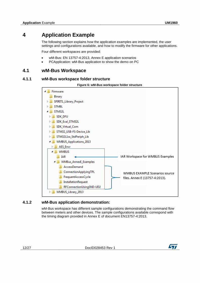
4.1.1 wM-Bus workspace folder structure
Figure 6: wM-Bus workspace folder structure
4.1.2 wM-Bus application demonstration:
wM-Bus workspace has different sample configurations demonstrating the command flow between meters and other devices. The sample configurations available correspond with the timing diagram provided in Annex E of document EN13757-4:2013.

UM1960 Application Example
DocID028453 Rev 1 13/27
Figure 7: wM-Bus workspace overview
The sample configurations include:
Installation: corresponds to Figure E.2 — Installation timing of Annex E, EN13757-4:2013
Installation-meter: to flash on board designated as meter
Installation-conc: to flash on board designated as other device
Access Demand: Corresponds to Figure E.6 — Access demand of Annex E, EN13757-4:2013
AccessDemand-meter: to flash on board designated as meter
AccessDemand-conc: to flash on board designated as other device
Frequent Access Cycle: Corresponds to Figure E.5 — Time out, Frequent Access Cycle of Annex E, EN13757-4:2013
Frequent AccessCycle-meter: to flash on board designated as meter
FrequentAccessCycle-conc: to flash on board designated as other device
Connection applying long/short transport layer: Corresponds to Figure E.4 — Connection applying short transport layer of Annex E, EN13757-4:2013

Application Example UM1960
14/27 DocID028453 Rev 1
ConnectionApplyingTPL-meter: to flash on board designated as meter
ConnectionApplyingTPL-conc: to flash on board designated as other device
RF-connection using SND-UD2: Figure E.7 — RF-connection using SND-UD2 of Annex E, EN13757-4:2013
RFConnectionUsingSND-UD2-meter: to flash on board designated as meter
RFConnectionUsingSND-UD2-conc: to flash on board designated as other device
4.2 PC application demonstration
The PC application uses the protocol format shown below to communicate with the
firmware. The GUI binary file can be found in the Firmware/Binary folder as
WMBUS_GUI.hex.
Figure 8: Packet flow
To use this workspace, you must install the “wM-Bus Demo Suite”. The installation procedure is provided further down in this document.

UM1960 Application Example
DocID028453 Rev 1 15/27
Figure 9: wM-Bus Demo Suite Interface

Hardware description UM1960
16/27 DocID028453 Rev 1
5 Hardware description
5.1 STEVAL-IKR002Vx (main board)
Figure 10: STEVAL- IKR002Vx main board
A: Mini USB connector CN1
B: Jumper JP1 (position 1-2 = USB power source; position 2-3 = battery power source)
C: Green LED DL6 (shows board is powered ON)
D: LIS3DH ultra-low power high performance three axes linear accelerometer
E: STLM75 high precision digital CMOS temperature sensor with I2C interface
F: Extension connector
G: User interaction buttons (RESET, PUSH_BUTTON, and JOY STICK)
H: JTAG connector
I: Five LEDs (DL1: green, DL2: orange, DL3: red, DL4: blue, DL5: yellow)
M: Daughterboard test points
L: RF module interface connector
The RF main board has an STM32L microcontroller used for driving the SPIRIT1 transceiver and to communicate to a PC via USB.
A connector on the main board (STEVAL- IKR002Vx main board) provides JTAG interface access for programming and debugging. The board can be powered via a mini-USB connector that can also be used for I/O interaction with a USB Host. The board has also a user button, a joystick and RESET button for user interaction. A temperature sensor and accelerometer are included in the board.
The RF module can be easily connected through a dedicated interface.
UM1960 Hardware description
DocID028453 Rev 1 17/27
Below is a list of some of the features available on the board:
STM32L151RBT6 64-pin microcontroller
Mini USB connector for power supply and I/O
JTAG connector
RF daughterboard interface
One RESET button and one USER button
One LIS3DH accelerometer
One STLM75 temperature sensor
One joystick
5 LEDs
One PWR LED
One battery holder for 2 AAA batteries
One row of test points on the interface with the RF daughterboard
5.1.1 Push buttons and joystick
For user interaction, the board has two buttons: one to reset the microcontroller and the other available for use by the application. There is also a digital joystick with 4 possible positions (left, right, up, down) (G in Figure 4: "wM-Bus Firmware Architecture").
5.1.2 JTAG connector
A JTAG connector on the board (H in Figure 4: "wM-Bus Firmware Architecture") allows programming and debugging of the STM32L microcontroller on board, using an in-circuit debugger and programmer like the ST-LINK/V2.
5.1.3 LEDs
Five LEDs are available (I in STEVAL- IKR002Vx main board)
DL1: Green
DL2: Orange
DL3: Red
DL4: Blue
DL5: Yellow
5.2 STEVAL-IKR002Vx (RF module)
The RF module includes five possible BOM lists on the same layout PCB Each one optimized for the following different RF bands:
169 MHz
315 MHz
433 MHz
868 MHz
915 MHz
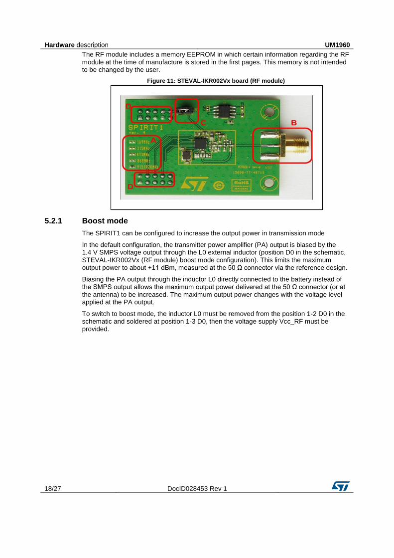
The band is indicated by a dummy resistor in region “A” of Figure 2: "Typical application scenario". An SMA connector on the RF module at “B” allows connection of RF instruments like spectrum analyzers and signal generators to the SPIRIT1 via RF cable or antenna (also included in the demo kit). The connector at “D” is used to connect with the main board to receive power and communicate via SPI and some GPIOs with the microcontroller.
The Vcc_RF pin on the RF daughterboard is connected to the Vbat pin of the SPIRIT1 through the jumper at “C”, which can be removed to measure current consumption.
Hardware description UM1960
18/27 DocID028453 Rev 1
The RF module includes a memory EEPROM in which certain information regarding the RF module at the time of manufacture is stored in the first pages. This memory is not intended to be changed by the user.
Figure 11: STEVAL-IKR002Vx board (RF module)
5.2.1 Boost mode
The SPIRIT1 can be configured to increase the output power in transmission mode
In the default configuration, the transmitter power amplifier (PA) output is biased by the 1.4 V SMPS voltage output through the L0 external inductor (position D0 in the schematic, STEVAL-IKR002Vx (RF module) boost mode configuration). This limits the maximum output power to about +11 dBm, measured at the 50 Ω connector via the reference design.
Biasing the PA output through the inductor L0 directly connected to the battery instead of the SMPS output allows the maximum output power delivered at the 50 Ω connector (or at the antenna) to be increased. The maximum output power changes with the voltage level applied at the PA output.
To switch to boost mode, the inductor L0 must be removed from the position 1-2 D0 in the schematic and soldered at position 1-3 D0, then the voltage supply Vcc_RF must be provided.

UM1960 Hardware description
DocID028453 Rev 1 19/27
Figure 12: STEVAL-IKR002Vx (RF module) boost mode configuration
For more information, see Application note AN4198 - SPIRIT1: increasing the output power, available on the SPIRIT1 web site or in the document folder of this release.
5.3 Hardware setup
This section describes the hardware and software setup procedures It also describes the system setup required for the above.
5.3.1 Hardware equipment
The following hardware components are required:
Two STEVAL-IKR002Vx main boards
Two SPIRIT1 daughterboards
One USB type-A to Mini-B USB cable to connect the boards to the PC
5.3.2 Setting up the board
The STEVAL-IKR002Vx main board is connected to the SPIRIT1 module as per the figure below.
Board setup
5.4 Running sample applications on the STEVAL-IKR002Vx board
Follow these steps to run the basic application demo:
1. use the appropriate tool chain IDE; i.e., IAR v7.2 2. power the STEVAL-IKR002Vx main board using the Mini-B USB cable 3. program the firmware in the STM32 on the STEVAL-IKR002Vx main board using the
firmware example provided 4. reset the MCU board using the RESET button on the STEVAL-IKR002Vx main board

Hardware description UM1960
20/27 DocID028453 Rev 1
5. ensure that meter and concentrator devices have the same RF frequency and mode settings
6. modify the parameters in “user_config.h” shown below to the desired settings
Figure 13: User firmware settings
UM1960 Using the demo board with PC application
DocID028453 Rev 1 21/27
6 Using the demo board with PC application
The PC application can be used to quickly familiarize yourself with ST’s wM-Bus package features. The board flashed with PC application firmware must be connected to the PC-GUI through a USB port.
6.1 wM-Bus Demo Suite system requirements
To install and run the application successfully, your pc must have the following minimum characteristics:
1 GHz processor
1 GB RAM
250 MB free disk space
Windows 7 (SP1) or later (x86 or x64)
.NET Framework 4.5
minimum HD (1280x720) / WXGA (1280x768) screen resolution – although a higher resolution is recommended
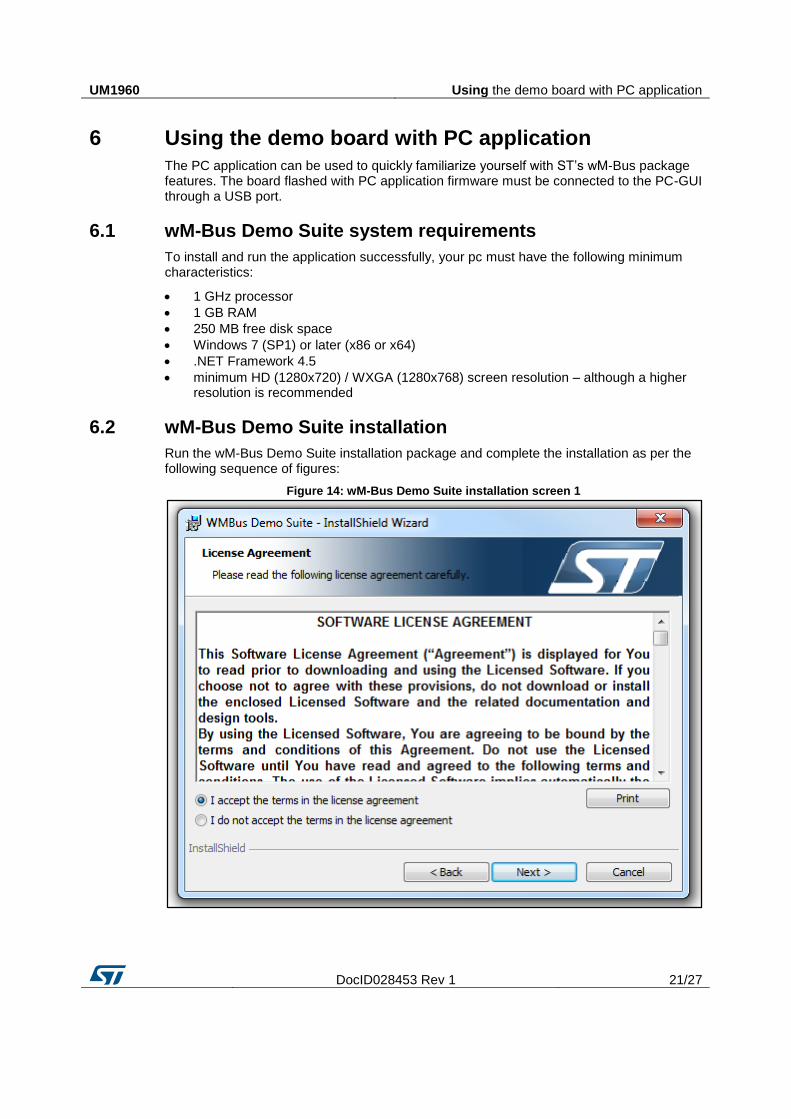
6.2 wM-Bus Demo Suite installation
Run the wM-Bus Demo Suite installation package and complete the installation as per the following sequence of figures:
Figure 14: wM-Bus Demo Suite installation screen 1

Using the demo board with PC application UM1960
22/27 DocID028453 Rev 1
Figure 15: wM-Bus Demo Suite installation screen 2

UM1960 Using the demo board with PC application
DocID028453 Rev 1 23/27
Figure 16: wM-Bus Demo Suite installation screen 3

Using the demo board with PC application UM1960
24/27 DocID028453 Rev 1
Figure 17: wM-Bus Demo Suite installation screen 4
Once installation is complete, also install the STMicroelectronics Virtual COM port driver present in the “Demo Suite” installation directory. Select the right installation file for your machine (32 or 64 bit).

UM1960 References
DocID028453 Rev 1 25/27
7 References
1. SPIRIT1 device datasheet 2. Respective STM32 controller datasheets

Revision history UM1960
26/27 DocID028453 Rev 1
8 Revision history Table 2: Document revision history
Date Version Changes
14-Dec-2015 1 Initial release.

UM1960
DocID028453 Rev 1 27/27
IMPORTANT NOTICE – PLEASE READ CAREFULLY
STMicroelectronics NV and its subsidiaries (“ST”) reserve the right to make changes, corrections, enhancements, modifications, and improvements to ST products and/or to this document at any time without notice. Purchasers should obtain the latest relevant information on ST products before placing orders. ST products are sold pursuant to ST’s terms and conditions of sale in place at the time of order acknowledgement.
Purchasers are solely responsible for the choice, selection, and use of ST products and ST assumes no liability for application assistance or the design of Purchasers’ products.
No license, express or implied, to any intellectual property right is granted by ST herein.
Resale of ST products with provisions different from the information set forth herein shall void any warranty granted by ST for such product.
ST and the ST logo are trademarks of ST. All other product or service names are the property of their respective owners.
Information in this document supersedes and replaces information previously supplied in any prior versions of this document.
© 2015 STMicroelectronics – All rights reserved


![SPIRIT1 Development Kit Software Package · 2016. 3. 28. · SPIRIT1 Development Kit content [1/3] • SPIRIT1 Library (STM32L, STM8L) • Spirit1 low level drivers: APIs to manage](https://static.fdocuments.us/doc/165x107/60f9e25cb746cc198847c12c/spirit1-development-kit-software-2016-3-28-spirit1-development-kit-content.jpg)