UM0220 User manual - systembussystembus.com/databook/Sensor/Camera VS6724Q0FB/Camera...UM0220 User...
35
February 2007 Rev 3 1/35 UM0220 User manual x24 Camera integration kit Description The x24 camera integration kit is designed to demonstrate the features of the VS6x24 single chip camera module. The camera integration kit consists of a baseboard and a plug-in board, containing a VS6x24 device in a socket package. Figure 1 shows the base board with the socket plug-in attached. Software is provided which allows easy demonstration of the available features. An external interface allows access to the camera data and control signals, allowing the user to pass video data directly to their application. The user will be able to control the camera through the USB 2.0 interface, or through their own application. Initially, the camera must be set up using the USB 2.0 interface, after which the camera can be used in conjunction with both the USB 2.0 interface and the user’s application, or with the user’s application as a stand alone module. Figure 1. IMG-x24-E01 image This user guide will assist you in setting up the hardware and software required to successfully evaluate the VS6x24 module. Part Number Description IMG-524-E01 Camera integration kit for VS6524 single chip VGA camera module IMG-624-E01 Camera integration kit for VS6624 single chip 1.3 MP camera module IMG-724-E01 Camera integration kit for VS6724 single chip 2 MP camera module www.st.com
Transcript of UM0220 User manual - systembussystembus.com/databook/Sensor/Camera VS6724Q0FB/Camera...UM0220 User...

February 2007 Rev 3 1/35
UM0220User manual
x24 Camera integration kit
DescriptionThe x24 camera integration kit is designed to demonstrate the features of the VS6x24 single chip camera module. The camera integration kit consists of a baseboard and a plug-in board, containing a VS6x24 device in a socket package. Figure 1 shows the base board with the socket plug-in attached. Software is provided which allows easy demonstration of the available features. An external interface allows access to the camera data and control signals, allowing the user to pass video data directly to their application. The user will be able to control the camera through the USB 2.0 interface, or through their own application. Initially, the camera must be set up using the USB 2.0 interface, after which the camera can be used in conjunction with both the USB 2.0 interface and the user’s application, or with the user’s application as a stand alone module.
Figure 1. IMG-x24-E01 image
This user guide will assist you in setting up the hardware and software required to successfully evaluate the VS6x24 module.
Part Number Description
IMG-524-E01 Camera integration kit for VS6524 single chip VGA camera module
IMG-624-E01 Camera integration kit for VS6624 single chip 1.3 MP camera module
IMG-724-E01 Camera integration kit for VS6724 single chip 2 MP camera module
www.st.com

Contents UM0220
2/35
Contents
1 Kit contents . . . . . . . . . . . . . . . . . . . . . . . . . . . . . . . . . . . . . . . . . . . . . . . . 4
2 PC requirements . . . . . . . . . . . . . . . . . . . . . . . . . . . . . . . . . . . . . . . . . . . . 5
2.1 PC specification . . . . . . . . . . . . . . . . . . . . . . . . . . . . . . . . . . . . . . . . . . . . . 5
2.2 USB 2.0 requirements . . . . . . . . . . . . . . . . . . . . . . . . . . . . . . . . . . . . . . . . 5
3 PC setup . . . . . . . . . . . . . . . . . . . . . . . . . . . . . . . . . . . . . . . . . . . . . . . . . . . 6
3.1 Windows update . . . . . . . . . . . . . . . . . . . . . . . . . . . . . . . . . . . . . . . . . . . . . 6
3.2 Monitor setup . . . . . . . . . . . . . . . . . . . . . . . . . . . . . . . . . . . . . . . . . . . . . . . 6
4 Laptop power management . . . . . . . . . . . . . . . . . . . . . . . . . . . . . . . . . . . 7
5 Software installation . . . . . . . . . . . . . . . . . . . . . . . . . . . . . . . . . . . . . . . . . 8
5.1 Troubleshooting the installation . . . . . . . . . . . . . . . . . . . . . . . . . . . . . . . . . 8
5.2 Installation known issues . . . . . . . . . . . . . . . . . . . . . . . . . . . . . . . . . . . . . . 9
6 Hardware setup . . . . . . . . . . . . . . . . . . . . . . . . . . . . . . . . . . . . . . . . . . . . 10
7 Software operation . . . . . . . . . . . . . . . . . . . . . . . . . . . . . . . . . . . . . . . . . 11
7.1 Streaming . . . . . . . . . . . . . . . . . . . . . . . . . . . . . . . . . . . . . . . . . . . . . . . . . 11
7.1.1 Logging . . . . . . . . . . . . . . . . . . . . . . . . . . . . . . . . . . . . . . . . . . . . . . . . . 12
7.2 Color . . . . . . . . . . . . . . . . . . . . . . . . . . . . . . . . . . . . . . . . . . . . . . . . . . . . . 14
7.3 Exposure . . . . . . . . . . . . . . . . . . . . . . . . . . . . . . . . . . . . . . . . . . . . . . . . . 15
7.4 Image . . . . . . . . . . . . . . . . . . . . . . . . . . . . . . . . . . . . . . . . . . . . . . . . . . . . 16
7.5 Miscellaneous . . . . . . . . . . . . . . . . . . . . . . . . . . . . . . . . . . . . . . . . . . . . . . 17
7.6 Image capture . . . . . . . . . . . . . . . . . . . . . . . . . . . . . . . . . . . . . . . . . . . . . 18
7.7 Capturing the image data from the camera . . . . . . . . . . . . . . . . . . . . . . . 19
7.8 Configuration scripts . . . . . . . . . . . . . . . . . . . . . . . . . . . . . . . . . . . . . . . . 21
7.9 V2Wreg . . . . . . . . . . . . . . . . . . . . . . . . . . . . . . . . . . . . . . . . . . . . . . . . . . 22
8 Hardware settings . . . . . . . . . . . . . . . . . . . . . . . . . . . . . . . . . . . . . . . . . . 24
8.1 Sensor plug-ins . . . . . . . . . . . . . . . . . . . . . . . . . . . . . . . . . . . . . . . . . . . . 24
8.2 Clock source . . . . . . . . . . . . . . . . . . . . . . . . . . . . . . . . . . . . . . . . . . . . . . . 24

UM0220 Contents
3/35
8.3 Power supplies . . . . . . . . . . . . . . . . . . . . . . . . . . . . . . . . . . . . . . . . . . . . . 24
8.4 USB 2.0 capture system . . . . . . . . . . . . . . . . . . . . . . . . . . . . . . . . . . . . . . 25
8.5 Chip Enable (CE) . . . . . . . . . . . . . . . . . . . . . . . . . . . . . . . . . . . . . . . . . . . 25
8.6 I2C . . . . . . . . . . . . . . . . . . . . . . . . . . . . . . . . . . . . . . . . . . . . . . . . . . . . . . 25
9 Design in methodology . . . . . . . . . . . . . . . . . . . . . . . . . . . . . . . . . . . . . . 26
9.1 Generate log file . . . . . . . . . . . . . . . . . . . . . . . . . . . . . . . . . . . . . . . . . . . . 26
9.2 Refine log file . . . . . . . . . . . . . . . . . . . . . . . . . . . . . . . . . . . . . . . . . . . . . . 29
9.3 Run directly on target application . . . . . . . . . . . . . . . . . . . . . . . . . . . . . . . 30
10 Tested USB 2.0 card list . . . . . . . . . . . . . . . . . . . . . . . . . . . . . . . . . . . . . 33
11 Revision history . . . . . . . . . . . . . . . . . . . . . . . . . . . . . . . . . . . . . . . . . . . 34

Kit contents UM0220
4/35
1 Kit contents
● Camera integration kit base board (PCB1248 RevB)
● Socket plug-in
● USB cable
● Tripod and mount
● Rubber feet
● Quick start guide

UM0220 PC requirements
5/35
2 PC requirements
The evaluation kit uses the USB 2.0 interface to connect to the host PC. In addition to the evaluation kit, you will require a PC with native USB 2.0 or an add-on card to provide this interface.
2.1 PC specificationTable 1 lists the recommended specification required to display the full frame rate (30 fps), users with a lower PC specification may be able to display at lower frame rates.
2.2 USB 2.0 requirementsAs the board requires high USB 2.0 bandwidth you must connect it directly to an available USB 2.0 port. Do not use any other USB devices (other than mouse / keyboard) while using the board.
Note: Not all USB 2.0 cards provide the same performance. We recommend that all USB 2.0 computers and add-on cards are USB 2.0 High Speed Certified and display the USB IF logo (shown on the right). A list of tested cards is available at the end of this document.
Table 1. PC specification
Parameter Recommended
Processor speed (MHz) 1 GHz
Memory (MB) 512
Graphics AGP 32-bit color
Display 1280 x 1024
USB 2.0 Intel North Bridge (Internal)
Operating system Windows XP SP2
PC setup UM0220
6/35
3 PC setup
Before installing the software you must ensure that your PC is running the latest service packs and is setup to give you the best image quality.
3.1 Windows updateConnect to the internet and using the Internet Explorer browser open http://windowsupdate.microsoft.com You must ensure that all updates are installed (critical updates, service packs, Windows updates and driver updates). This will ensure that you have the latest USB 2.0 drivers and DirectX components required by the evaluation kit software.
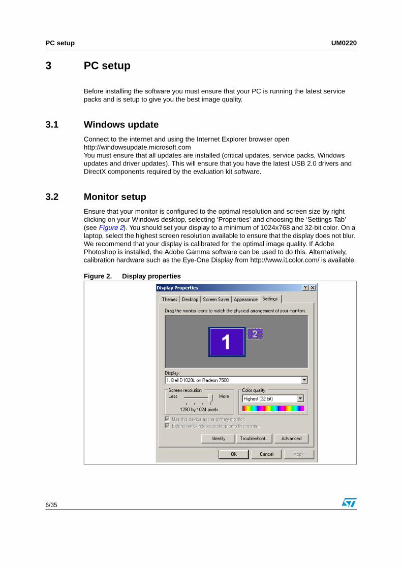
3.2 Monitor setupEnsure that your monitor is configured to the optimal resolution and screen size by right clicking on your Windows desktop, selecting ‘Properties’ and choosing the ‘Settings Tab’ (see Figure 2). You should set your display to a minimum of 1024x768 and 32-bit color. On a laptop, select the highest screen resolution available to ensure that the display does not blur. We recommend that your display is calibrated for the optimal image quality. If Adobe Photoshop is installed, the Adobe Gamma software can be used to do this. Alternatively, calibration hardware such as the Eye-One Display from http://www.i1color.com/ is available.
Figure 2. Display properties

UM0220 Laptop power management
7/35
4 Laptop power management
Laptop computers can show significantly lower performance than an equivalent desktop PC. This is the result of a more complex architecture where power management software tries to balance battery life with processor performance. We advise that the following steps are taken to ensure that equivalent performance can be obtained.
When using a laptop with the evaluation kit, the laptop should be connected to the main power supply through its power adaptor. This will improve processor speed and will often increase the power to the display allowing for greater brightness and clarity.
If a Cardbus USB 2.0 card is used, this must also be powered through a wall adaptor. Be careful when choosing a Cardbus card to ensure that an adaptor is supplied. This will allow the evaluation board to receive enough power to operate over the USB cable.
Power management should be turned off or minimized. Suspend and hibernate must also be disabled. To do this double click on ‘Power Options’ in the Control Panel and select the ‘Always On’ Scheme. Ensure that ‘System Standby’ and ‘System Hibernates’ are set to ‘Never’ (see Figure 3). Selecting ‘Always On’ will ensure that the processor runs at full speed.
There may be other power management settings in your laptop BIOS. Your laptop manual should be consulted for further details if these are set.
Figure 3. Power options properties

Software installation UM0220
8/35
5 Software installation
Before the evaluation board is connected to your PC, the software must be installed to support it.
Installation
● Ensure that NO ST USB2.0 camera integration kit or other ST evaluation kit (EVK) device is connected during installation.
● Ensure you have administrator privileges on your PC.
● Ensure that Direct X 9.0 or better is installed and ‘Windows Update’ has been run and all updates including service packs are current.
● Run the installer “x24Demo.msi” (please check for latest version).
● The installer will install a number of applications as well as the driver for the camera, please hit ‘Next’ when requested.
● When the installation is complete, plug in the hardware.
● You may be informed about an unsigned driver, click ‘Continue’ to finish the installation. You will have to do this twice.
Operation
● Plug in your camera integration kit base board.
● Shortly after connection the red LEDs, D1 and D2 (firmware ready), will come on (both located on the front of the board). Both will then go off and come back on again (and stay lit). This indicates that the EVK is now configured and ready for use.
● Once the power has been setup correctly the green LEDs, D4 (digital power) and D5 (analog power), will come on and stay on. If they are not, please ensure that all relevant jumpers are in place.
● Run the evaluation software by double clicking the ‘x24 Demo’ shortcut that has been placed on your desktop.
● Do not boot or shutdown your PC with this device attached.
5.1 Troubleshooting the installationIf you encounter a problem during the installation, please check the following:
● Check that PC hardware meets the minimum specifications detailed in Section 2.1.
● Ensure that the EVK board is connected to a USB 2.0 port.
● Check that all Windows Updates and service packs are installed from http://windowsupdate.microsoft.com.
● Check that DirectX 9.0 or later is installed:(Start Button -> Run -> type “dxdiag” -> hit OK).
● Check that the USB cable works with a different device.
● Check that other USB 2.0 devices work on the PC.
● Check the device appears in device manager.
● Ensure that power management is set to ‘Always On’.
● Try using a different PC if possible.

UM0220 Software installation
9/35
5.2 Installation known issues
It is possible that, owing to an issue with certain OEM versions of Windows XP SP1, you may experience problems installing USB device drivers - including the one supplied for the x24 camera integration kit. Such problems may include the 'Found New Hardware' wizard not appearing on connecting the device, or the device appearing as 'USB Device' in the Windows device manager.
There are two approaches to fixing this problem. The first is to disconnect the device, install Windows XP service pack 2, re-install the x24 camera integration kit, then reconnect the device.
If it is not possible to install SP2 then the device should be installed manually by following the instructions below.
Also, the following steps should be carried out in the event that the message 'Cannot open handle to USB 2.0 device' is displayed when the device is plugged in and the evaluation application is started.
1. Right-click 'My Computer' and select 'Properties'.
2. On the 'Hardware' tab, select 'Device Manager'.
3. Right-click the item labelled 'USB Device' and select 'Update Driver'.
4. In the 'Hardware Update Wizard', select 'Install from a list or specific location' and click 'Next'.
5. Select 'Don't search. I will choose the driver to install.'
6. Select 'STV0EVK Camera' and click next.
7. If the 'Hardware Installation' dialog appears, select 'Continue Anyway'.
8. Allow windows to complete the installation.
9. In device manager, right-click the item labelled 'STV0EVK Camera' (or 'Mobile EVK') and select 'Update Driver'.
10. In the 'Hardware Update Wizard', select 'Install from a list or specific location' and click 'Next'.
11. Select 'Don't search. I will choose the driver to install.'
12. From the 'Common Hardware Types' list, select 'Imaging devices' and click 'Next'.
13. Select 'STV0EVK Camera' and click next.
14. If the 'Hardware Installation' dialog appears, select 'Continue Anyway'.
15. Allow windows to complete the installation.
Problems
If you are still having problems, please quote the following when requesting support:
● Computer make and model
● Processor speed
● Amount of installed memory
● Operating system and service pack
● USB 2.0 card make and model

Hardware setup UM0220
10/35
6 Hardware setup
The EVK board has been configured to take power from its USB connection. However, as illustrated in Chapter 9, you can also supply power through the board’s external interface.
Turn on your PC before connecting the EVK Board.
After use, we recommend that the EVK board is unplugged before you shutdown your PC.

UM0220 Software operation
11/35
7 Software operation
7.1 StreamingAfter installation a shortcut will appear on your desktop to allow you to access the x24 camera integration kit application. Double click on this icon and the following window will appear.
Figure 4. Streaming tab
Note: When this application starts up, a V2Wreg window opens but is then minimized, this does not affect the operation of the demonstration and will be described later.

Software operation UM0220
12/35
If you click on “Start”, which is within the ‘Streaming’ area, a window (or windows) displays the image as configured by the streaming properties.
● The ‘Stream1’ area controls the main window.
● The ‘Size control’ allows the user to set the resolution of the streaming image
● The ‘Format control’ allows selection of YUV422, RGB565 or RGB444.
● The ‘Stream2’ area controls the second ‘Viewlive’ window.
● The functions in the ‘Global streaming controls’ area can be adjusted while the image is streaming. Other streaming properties such as size and format can only be adjusted when streaming has been stopped.
● The frame rate can be adjusted by inputting the required value and hitting set.
● If the ‘Low Light’ box is set then the frame rate drops to 4 fps.
● When the format control is set to RGB the dithering effect can be enabled or disabled.
7.1.1 Logging
All changes made to the x24 camera integration kit are sent to V2WReg, which then communicates the appropriate register change to the VS6x24. More information is available on V2WReg in Section 7.9. Any changes you make to the sensor via the GUI are replicated in the Data Logger application as I2C writes, shown in Figure 5. Using the Data Logger, you can save the I2C writes as a V2WReg log file. The purpose of the log file is to help you in finding the optimum settings for your target application. The log file can be re-run at any time to re-create the saved settings. This design methodology also allows you to save scenario specific settings. The process of creating a log file is detailed in Section 9.1.

UM0220 Software operation
13/35
Figure 5. Data Logger application

Software operation UM0220
14/35
7.2 Color
Figure 6. Color tab
Within the color tab, there is a stream 1 area control, a stream 2 area control and a white balance area control.
● In the stream 1 area control, contrast, color saturation and gamma balance can be adjusted for stream 1.
● In the stream 2 area control, the contrast, color saturation and gamma balance can be adjusted for stream 2.
● In the white balance area control, the white balance can be selected from either auto, manual, or a choice of presets.
– When Manual is selected the R,G and B can be adjusted independently.

UM0220 Software operation
15/35
7.3 Exposure
Figure 7. Exposure tab
Flicker frequency, exposure weighting and compensation can be adjusted in this window.
In the flicker correction area, the 50/60Hz frequency present in lighting (due to fluorescent lighting) can be cancelled by the system.
The weighting control area changes the area of the image used to gain statistics for the exposure algorithm. The different settings available are explained below:
● Flat - uniform gain associated with all pixels;
● Backlit - more gain associated with the center and the bottom pixels;
● Centered - more gain associated with center pixels.
The exposure compensation area controls the exposure algorithm, the exposure compensation is expressed in EV (Exposure Value).

Software operation UM0220
16/35
7.4 Image
Figure 8. Image tab
The gain, coring threshold and image orientation can be adjusted in this window.
Within the sharpness area controls, two parameters can be changed:
● Sharpness gain
● Coring threshold, which adjusts the point at which the gain is applied. The coring threshold is used to stop the sharpening gain being applied to very small changes in the image (that is noise).
The orientation area control can be used to alter the output image so that it appears to be horizontally mirrored or vertically flipped. The horizontal mirror and vertical flip can be applied to stream 1, note that only mirror is available when view live mode is selected.

UM0220 Software operation
17/35
7.5 Miscellaneous
Figure 9. Miscellaneous tab
The output format selection controls the method of data synchronization used in the capture system. The user has three options here:
● Embedded codes (embedded 1)
● Embedded codes (embedded 2)
● Hardware signals (external)
Changing the output format is transparent to the user.

Software operation UM0220
18/35
The image quality profile shows the flexibility of the VS6x24 image control pipe. In this area, the user has three options:
● Default - optimized settings for a normal scene
● Dynamic - higher color saturation, higher exposure setting with increased sharpness to give dynamic image.
● Smooth - lower color saturation, lower exposure to give a softer image.
7.6 Image captureAn image can be captured using the “Grab” button, when this button is pressed an image frame is captured from the stream and displayed in a separate ‘Still’ window. Repeated pressing of the “Grab” button will overwrite the image in the ‘Still’ window.
To save the image which appears in the ‘Still’ window, move the mouse pointer over the image and right click, select ‘File’, ‘Save’ and ‘Bmp’, you will then be able to select location and file name.
Figure 10. Image grab
It is possible to right click on the ‘RGB’ window at any time and capture an image to file.
The image captured using this method is the rendered RGB 24 image used for display, this image rendering is done by the standard converter found in windows.

UM0220 Software operation
19/35
7.7 Capturing the image data from the camera1. Shut down the application then run it again.
2. Before hitting “Start” click anywhere in the application then hit Alt+S.The USBview application window will then appear.
3. Hit start, you will now be able to see the ‘RGB’ and a new window called ‘Ping’ (you will need to select it from the task bar), this is the received data from the x24, either YUV422, RGB565 or RGB444.
4. Right click in this window to capture the data.
Capturing Bayer data
Follow the procedure above for capturing prior to rendering and press stop on the x24 demo app. Please note that any changes made in V2WReg directly, that is not through the GUI, are not captured by the Data Logger.
1. In the V2Wreg application, select PipeSetupBank0/bdataformat0 = BAYER.
2. Then, select Mode Control/bUserCommand = RUN.

Software operation UM0220
20/35
Figure 11. V2Wreg pop up
In USBview capture dimensions window:
1. Change width (in clks) to 1288, height to 484, then hit apply ‘new configuration’.
2. Press ‘Start Capture’ on the USBview application. You will then see the RGB window displaying an incorrect image but the PING window will now show the BAYER data from the sensor.

UM0220 Software operation
21/35
7.8 Configuration scriptsAll scripts used by the application during initialization and operation of the VS6x24 device can be found in the following location;
C:\Program Files\STMicroelectronics\x24 Demo x-yz
By changing the values in some of these scripts it is possible to customize the operation of the camera application. An example of some of the configurations used for the VS6524 are shown below.
Note: Removing or changing some of the parameters may stop the demo application operating. If this occurs re-install the application. Note however that this will return all settings to default.
x24 Setttings.ini
[Profile_Default]
Contrast=130
Saturation=115
Gamma=15
Sharpness_Gain=14
Coring_Threshold=40
Exposure_Compensation=21
The defaults used for the 3 image profile settings: default, dynamic and smooth, can be modified to create custom profiles.
[Defaults]
Low_Light_Framerate=4
Initial_Framerate=15
Changing the above items will customize the frame rate used when the device starts up and the frame rate which is used when the “low light” box is ticked.

Software operation UM0220
22/35
7.9 V2Wreg
Figure 12. V2Wreg pop up
The V2Wreg application can be used to look at and modify the VS6x24 register settings directly. Note that the changes applied here are bypassing the demonstration software and are therefore not reflected back up to the higher level application. These changes may cause instability or in some cases the demonstration application to crash.

UM0220 Software operation
23/35
Please refer to the VS6x24 datasheet for further explanations of register functions.
Any changes made to V2WReg directly are recorded by the data logger. However, no comments will be recorded in the data logger. Therefore, if you are going to change parameters using V2WReg it is recommended that you also manually insert associated comments.

Hardware settings UM0220
24/35
8 Hardware settings
8.1 Sensor plug-insThe camera integration kit is supplied with one socket plug-in. Connectors J5 and J6 on the plug-in board connect to connectors J5 and J6 respectively on the base board.
8.2 Clock sourceA 12 MHz oscillator on the baseboard is used to provide the input clock to the VS6x24. Alternatively, an external clock can be supplied, through pin 32 of the customer connector. Jumper JP4 can be used to select whether the clock signal supplied to the camera device is external (EXT_CLK) or comes from the baseboard (INT_CLK).
8.3 Power suppliesThe VS6x24 requires a 2.8 V analog supply and a 1.8 V or 2.8 V, digital supply. There are three distinct ways of powering the base board:
1. Through the USB connection
2. By providing an arbitrary supply of between 2.8 V and 4.6 V through J2
3. By supplying precise digital (1.8 V/2.8 V) and analog (2.8 V) supples through pins 34 and 36, respectively, of J1
When power is supplied using method 1 or 2 the input voltage is passed through two voltage regulators, one for analog power and one for digital. When power is supplied using method 3 the voltage regulators are not required.
The origin of the power supply can be selected by moving jumpers into the appropriate positions. If you would like to use the supply from the voltage regulators, whether it be power from the USB supply, or an arbitrary voltage supplied through the external power supply, J2, then jumpers JP2 and JP3 must be moved to the INT_VDIG and INT_VANA positions respectively. If the baseboard is powered through the USB supply, then jumper JP1 must be moved to position USB_POWER, if the external power supply, J2, is to be used then this jumper must be left in the EXT_POWER position. The configuration of jumpers JP1, JP2 and JP3 to allow power to be input through J2 is shown in Figure 13.
Figure 13. Configuration of jumpers JP1, JP2 and JP3 for supplying power through J2
VREG VREG
EXT_VDIG EXT_VANA
EXT_POWERUSB_POWER
VDIG VANA
INT_VDIG INT_VANA
JP1
JP2 JP3

UM0220 Hardware settings
25/35
If precise voltages are to be supplied for digital and analog voltages through pins 34 and 36 of J1 respectively the jumpers JP2 and JP3 must be moved to positions EXT_VDIG and EXT_VANA respectively. No jumper is required for JP1 as, in this case, it has no bearing on the origin of the power supply. The configuration of jumpers JP1, JP2 and JP3 to allow power to be input through J1 is shown in Figure 14.
Figure 14. Configuration of jumpers JP1, JP2 and JP3 for supplying power through J1
No matter which method is used to supply power, the Level Shifter must be supplied with the base board output voltage level through pin 38 of J1, either 1.8 V, 2.5 V or 3.3 V.
8.4 USB 2.0 capture systemThe EVK baseboard uses a high speed USB 2.0 microcontroller. This allows 8-bit data from the VS6x24 to be transmitted to a PC and displayed on screen.
LEDs D1 and D2 will indicate when the EVK has enumerated as a camera device. A serial EEPROM (U2) contains enumeration information such as the VID and PID.
8.5 Chip Enable (CE)The VS6x24 has an active high chip enable signal (CE). This signal is normally driven by the demo software. However, the CE signal can also come from an external source. Jumper JP5 determines whether the CE supplied to the camera device comes from the baseboard (INT_CE) or from an external source (EXT_CE). The external CE is supplied through pin 30 of the customer connector.
8.6 I2CThe I2C control signals, SDA and SCL can be supplied by the demo software. You can also supply these signals externally. If you wish to supply I2C signals then jumpers JP6 and JP7 must be moved to the EXT_SDA and EXT_SCL positions respectively. Leaving these jumpers in the INT_SDA and INT_SCL positions means the baseboard expects the I2C signals to be supplied by the demo software. I2C control signals can be externally supplied through pins 26 (SDA) and 28 (SCL) of the external interface.
VREG VREG
EXT_VDIG EXT_VANA
EXT_POWERUSB_POWER
VDIG VANA
INT_VDIG INT_VANA
JP1
JP2 JP3
Irrelevant, asvoltage regulators
are bypassed

Design in methodology UM0220
26/35
9 Design in methodology
This section describes how you can use the x24 camera integration kit to supply streaming video to your application. There are three stages to this design-in methodology:
1. Generate log file
2. Refine log file
3. Run directly on target application
For stages 1 and 2, the demo board must be connected to the PC. For stage 3, you can attach the base board and the plug-in directly to your application, without it being connected to the PC. However, you must supply power and control signals to the demo board.
It should be noted that during stages 1 and 2 the x24 camera integration kit can be connected to the target application, though it is being driven by signals generated by the PC software and power is being supplied through the USB interface. To enable the camera to output data through J1, VLEVEL (pin 38 of J1) must be supplied with the appropriate voltage, either 1.8 V, 2.5 V or 3.3 V.
In stage 1 you will be able to use the GUI to configure the camera to your personal specification. Once you are happy with the camera output you can use the supplied software to save this configuration. It will be saved as a V2WReg log file, this file contains all I2C writes to the camera. Stage 1 is described in more detail in Section 9.1.
Stage 2 will allow you to run a software application that refines the log file created in stage 1 by removing unwanted I2C writes to the FPGA. This is essential, as in stage 3 the FPGA will not be utilized, attempting to write to the FPGA when it is not used may cause the system to crash. After the log file has been refined, the application then loads the refined log file into V2WReg and starts streaming video from the camera, allowing you to ensure that the refined log file has the same final properties as the image you produced using stage 1 of the design in methodology. Stage 2 is described in more depth in Section 9.2.
Stage 3 describes how to connect x24 camera integration kit to the target application so that you can run it without supplying power and control signals from the PC. To do this you must have some method of taking the I2C writes contained in the V2WReg log file and porting them to your target application. The target application must then be able to supply these I2C writes to the x24 camera integration kit through the external interface. Stage 3 is described in more depth in Section 9.3.
9.1 Generate log fileEnsure jumper JP1 is in the USB_POWER position, jumper JP2 is in the INT_VDIG position and JP3 is in the INT_VANA position, so that the baseboard is powered from the USB supply. Similarly, ensure that jumper JP4 is in the INT_CLK position, JP5 is in the INT_CE position, JP6 is in the INT_SDA position and JP7 is in the INT_SCL position. This determines that CLK, CE and I2C control signals are supplied by the baseboard hardware and demo software. The power configuration is shown in Figure 15 and the control configuration is shown in Figure 16.

UM0220 Design in methodology
27/35
Figure 15. Configuration for supplying power through USB
Figure 16. Configuration for using software control signals
Open the x24 camera integration kit GUI, shown in Figure 17, press 'Start', located in the streaming section.
Design in methodology UM0220
28/35
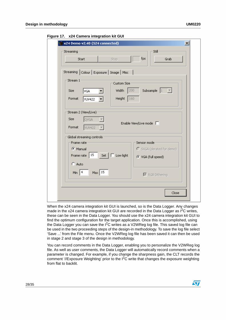
Figure 17. x24 Camera integration kit GUI
When the x24 camera integration kit GUI is launched, so is the Data Logger. Any changes made in the x24 camera integration kit GUI are recorded in the Data Logger as I2C writes, these can be seen in the Data Logger. You should use the x24 camera integration kit GUI to find the optimum configuration for the target application. Once this is accomplished, using the Data Logger you can save the I2C writes as a V2WReg log file. This saved log file can be used in the two proceeding steps of the design-in methodology. To save the log file select ‘Save ...’ from the File menu. Once the V2WReg log file has been saved it can then be used in stage 2 and stage 3 of the design in methodology.
You can record comments in the Data Logger, enabling you to personalize the V2WReg log file. As well as user comments, the Data Logger will automatically record comments when a parameter is changed. For example, if you change the sharpness gain, the CLT records the comment ‘//Exposure Weighting’ prior to the I2C write that changes the exposure weighting from flat to backlit.

UM0220 Design in methodology
29/35
9.2 Refine log fileEnsure that all jumpers remain in the same position as set out in Section 9.1.
The V2WReg log file saved in stage 1 contains I2C writes that configure the FPGA in the USB Interface part of the base board. These I2C writes set up the communication protocol used by the FPGA so that the USB 2.0 microprocessor can communicate with the sensor. When the log file created in Stage 1 is loaded into the Refiner and the user presses ‘Run’, these commands and other unnecessary I2C commands contained within the V2WReg log file are removed by the refiner application. The refiner application, shown in Figure 18, then launches V2WReg and loads the refined log file into V2WReg. USBView also launches to allow you to view the video being streamed from the sensor. The parameters of the video being streamed should match the parameters of the video that was streaming when the V2WReg log file was saved in stage 1.The refined log file is saved in the same directory as the log file created in Stage 1. The name of the refined log file is dependent upon the original input file. The naming convention for a refined log file is <original_file_name>_v2wreg_refined.txt. This file is the one that you should port to your application for stage 3, not the <original_ file_name>.txt.
Figure 18. Refiner application
The camera integration kit must be connected to the PC in both stages 1 and 2. Optionally, it may also be connected to the target application, as shown in Figure 19.
Figure 19. Connecting PC, demo board and target application for stages 1 and 2
Target
application
Level
shifter
Cameraplug-in
USB
2.0 I/FPC
VREGs
I2C
I2C
VideoVideo
Video
Video
Power
Power

Design in methodology UM0220
30/35
9.3 Run directly on target applicationThis stage integrates the x24 camera integration kit with the target application. Therefore, you should supply all clock, CE and I2C signals. On the baseboard, place jumper JP4 in position EXT_CLK, JP5 in position EXT_CE, JP6 in position EXT_SDA and JP7 in position EXT_SCL, the baseboard will now expect CLK, CE and I2C to be supplied externally, by you. This setup is shown in Figure 20. To do this you must have some method of taking the I2C writes contained in the V2WReg log file and porting them to the target application. The target application must then be able to supply these I2C writes to the x24 camera integration kit through the external interface.
Figure 20. Configuration of control signals
To configure the external power supply to the board, you have two choices. Firstly, you can supply power at exact voltages (2.8 V analog and 2.8 V, digital) through the external interface, J1, pin 34 for digital power and pin 36 for analog power. Or you can supply power at an arbitrary voltage, between 2.8 V and 4.6 V, through the external power supply, J2. If J2 is used to supply power then the arbitrary voltage supplied is passed through on board voltage regulators. The pinout for the external interface, J1, is shown in Figure 21.

UM0220 Design in methodology
31/35
Figure 21. External Interface pinout
To set up the board so that power can be supplied through J2, jumper JP1 must be placed in the EXT_POWER position, JP2 must be placed in the INT_VDIG position and JP3 must be placed in the INT_VANA position. This is shown in Figure 22.
Figure 22. Configuration for external power, through J2
To set up the board so that power can be supplied through J1, jumper JP2 must be placed in the EXT_VDIG position and JP3 must be placed in the EXT_VANA position. This is shown in Figure 23. Jumper JP1 is irrelevant in this case as it only determines whether USB power or external power is supplied to the voltage regulators. Exact voltages must be supplied through J1 for both analog and digital supplies. That is 2.8 V for analog and 2.8 V for digital.

Design in methodology UM0220
32/35
Figure 23. Configuration for external power, through J1
In this case, you load the created log file directly into the target application. The application can then write the commands captured in the log file to the camera through the I2C interface. The setup for stage 3, where the specified power levels required are supplied through the external interface, J1, is shown in Figure 24.
Figure 24. Connecting demo board and application for stand alone operation
As Figure 24 shows, all power and control signals are supplied by the user in stage 3 of the design-in methodology. Using the Viewer application, shown in Figure 25, you can view the video that is streaming from the VS6x24 to your target application. However, this is optional. If you would like to view the streaming video on your PC, follow these steps:
1. Open the Viewer.exe application.
2. Browse to, and select, the refined log file that you ported to your application.
3. Press ‘Run’ on the Viewer.
Figure 25. Viewer application GUI
Target
application
Level
shifter
Cameraplug-in
USB
2.0 I/FPC
VideoVideo
Power
I2C
I2CI2C
Power
Video
Video
J1
x24 Camera integration kit

UM0220 Tested USB 2.0 card list
33/35
10 Tested USB 2.0 card list
The following cards are both USB 2.0 compliant and have been tested to operate with the evaluation Kit.
On-board host controllers:
● Intel 855PM chipset
● Intel 845GE chipset
● SIS 645DX chipset
PCI cards:
● Belkin F5U220 (NEC chipset)
● Belkin F5U219 (NEC chipset)
● Orange Micro USB 2.0 PCI (NEC chipset)
Cardbus cards:
● Belkin FSU222 (NEC chipset)
● Sitecom USB 2.0 (NEC chipset)

Revision history UM0220
34/35
11 Revision history
Table 2. Document revision history
Date Revision Changes
6-Apr-2006 1 Initial release.
13-Apr-2006 2Reviewed the wording in the first two sentences of Chapter 9: Design in methodology.
20-Feb-2007 3Various text changes made in document to cover all x24 products (VS6524, VS6624, and VS6724).

UM0220
35/35
Please Read Carefully:
Information in this document is provided solely in connection with ST products. STMicroelectronics NV and its subsidiaries (“ST”) reserve theright to make changes, corrections, modifications or improvements, to this document, and the products and services described herein at anytime, without notice.
All ST products are sold pursuant to ST’s terms and conditions of sale.
Purchasers are solely responsible for the choice, selection and use of the ST products and services described herein, and ST assumes noliability whatsoever relating to the choice, selection or use of the ST products and services described herein.
No license, express or implied, by estoppel or otherwise, to any intellectual property rights is granted under this document. If any part of thisdocument refers to any third party products or services it shall not be deemed a license grant by ST for the use of such third party productsor services, or any intellectual property contained therein or considered as a warranty covering the use in any manner whatsoever of suchthird party products or services or any intellectual property contained therein.
UNLESS OTHERWISE SET FORTH IN ST’S TERMS AND CONDITIONS OF SALE ST DISCLAIMS ANY EXPRESS OR IMPLIEDWARRANTY WITH RESPECT TO THE USE AND/OR SALE OF ST PRODUCTS INCLUDING WITHOUT LIMITATION IMPLIEDWARRANTIES OF MERCHANTABILITY, FITNESS FOR A PARTICULAR PURPOSE (AND THEIR EQUIVALENTS UNDER THE LAWSOF ANY JURISDICTION), OR INFRINGEMENT OF ANY PATENT, COPYRIGHT OR OTHER INTELLECTUAL PROPERTY RIGHT.
UNLESS EXPRESSLY APPROVED IN WRITING BY AN AUTHORIZE REPRESENTATIVE OF ST, ST PRODUCTS ARE NOT DESIGNED,AUTHORIZED OR WARRANTED FOR USE IN MILITARY, AIR CRAFT, SPACE, LIFE SAVING, OR LIFE SUSTAINING APPLICATIONS,NOR IN PRODUCTS OR SYSTEMS, WHERE FAILURE OR MALFUNCTION MAY RESULT IN PERSONAL INJURY, DEATH, ORSEVERE PROPERTY OR ENVIRONMENTAL DAMAGE.
Resale of ST products with provisions different from the statements and/or technical features set forth in this document shall immediately voidany warranty granted by ST for the ST product or service described herein and shall not create or extend in any manner whatsoever, anyliability of ST.
ST and the ST logo are trademarks or registered trademarks of ST in various countries.
Information in this document supersedes and replaces all information previously supplied.
The ST logo is a registered trademark of STMicroelectronics. All other names are the property of their respective owners.
© 2007 STMicroelectronics - All rights reserved
STMicroelectronics group of companies
Australia - Belgium - Brazil - Canada - China - Czech Republic - Finland - France - Germany - Hong Kong - India - Israel - Italy - Japan - Malaysia - Malta - Morocco - Singapore - Spain - Sweden - Switzerland - United Kingdom - United States of America
www.st.com