Directive technique - Câblage universel de communication ...
Ultraviolet communication technique and its applicationLiang Guo, Yanan Guo, Junxi Wang, and Tongbo Wei
Citation: L Guo, Y N Guo, J X Wang, and T B Wei, Ultraviolet communication technique and its application[J]. J. Semicond., 2021,42(8), 081801.
View online: https://doi.org/10.1088/1674-4926/42/8/081801
Articles you may be interested in
Wireless communication and wireless power transfer system for implantable medical device
Journal of Semiconductors. 2020, 41(10), 102403 https://doi.org/10.1088/1674-4926/41/10/102403
High-speed photodetectors in optical communication system
Journal of Semiconductors. 2017, 38(12), 121001 https://doi.org/10.1088/1674-4926/38/12/121001
A high-speed power detector MMIC for E-band communication
Journal of Semiconductors. 2017, 38(8), 085002 https://doi.org/10.1088/1674-4926/38/8/085002
Flexible ultraviolet photodetectors based on ZnO–SnO2 heterojunction nanowire arrays
Journal of Semiconductors. 2018, 39(2), 024002 https://doi.org/10.1088/1674-4926/39/2/024002
Deep-ultraviolet integrated photonic and optoelectronic devices: A prospect of the hybridization of group III–nitrides, III–oxides, andtwo-dimensional materials
Journal of Semiconductors. 2019, 40(12), 121801 https://doi.org/10.1088/1674-4926/40/12/121801
Fabrication of room temperature continuous-wave operation GaN-based ultraviolet laser diodes
Journal of Semiconductors. 2017, 38(5), 051001 https://doi.org/10.1088/1674-4926/38/5/051001
Follow JOS WeChat public account for more information

Ultraviolet communication technique and its application
Liang Guo1, 2, 3, Yanan Guo1, 2, 3, Junxi Wang1, 2, 3, and Tongbo Wei1, 2, 3, †
1Research and Development Center for Semiconductor Lighting Technology, Institute of Semiconductors, Chinese Academy of Sciences,Beijing 100083, China2Center of Materials Science and Optoelectronics Engineering, University of Chinese Academy of Sciences, Beijing 100049, China3Beijing Engineering Research Center for the 3rd Generation Semiconductor Materials and Application, Beijing 100083, China
Abstract: With recent developments of deep ultraviolet (DUV) light-emitting diodes and solar-blind detectors, UV communica-tion (UVC) shows great potential in replacing traditional wireless communication in more and more scenarios. Based on the at-mospheric scattering of UV radiation, UVC has gained considerable attention due to its non-line-of-sight ability, omnidirection-al communication links and low background noise. These advantages make UVC an ideal option for covert secure communica-tion, especially for military communication. In this review, we present the history and working principle of UVC with a special fo-cus on its light sources and detectors. Comprehensive comparison and application of its light sources and detectors areprovided to the best of our knowledge. We further discuss the future application and outlook of UVC. Hopefully, this reviewwill offer valuable insights into the future development of UVC.
Key words: ultraviolet communication; non-line-of-sight; optical wireless communication
Citation: L Guo, Y N Guo, J X Wang, and T B Wei, Ultraviolet communication technique and its application[J]. J. Semicond., 2021,42(8), 081801. http://doi.org/10.1088/1674-4926/42/8/081801
1. Introduction
Optical wireless communication (OWC) has been a re-search hot spot for decades[1]. From ultraviolet (UV) light to in-frared (IR) light, OWC has been extensively studied. As themost popular optical communication technology, visible lightcommunication (VLC) has received worldwide attention dueto its over 10 Gb/s data rate and lower than 3.8 × 10–3 bit-error-rate (BER), which shows great potential in indoor high-speedcommunication[2]. The development of VLC has largely be-nefited from the development of light sources, especially vis-ible light-emitting diodes (LEDs) technology. With the recentdevelopment of deep ultraviolet (DUV) LEDs and solar-blinddetectors, ultraviolet communication (UVC) is drawing moreand more attention too.
As a novel communication technique, UVC utilizes UV radi-ation to transmit signals which can be scattered and reflec-ted by the particles and aerosols floating in the air. Its transmis-sion range can be extended up to several kilometers regard-less of the topographic features on the ground. Compared totraditional wireless communication, UVC has several uniquefeatures that render it a promising communication tech-nique for future applications. Traditional wireless communica-tion demands an obstacle-free communication channelbetween transceivers, while UVC can easily bypass theseobstacles through scattering and reflection. The UV radiationemployed in communication is also called solar-blind radi-ation which is located between 200–280 nm in the DUV spec-trum. Most solar-blind radiation is absorbed by ozone and oxy-gen when passing through the atmosphere, which leaves alow background-noise communication channel near the
ground[3]. Furthermore, the power of DUV radiation drops ex-ponentially with the transmission distance, which limits itspropagation and makes it an ideal option for short-range com-munication. In radio-silent scenarios, UVC can work as an al-ternative to conventional wireless communication. Fig. 1shows an example of UVC system and network[4]. Recently,Alkhazragi et al. demonstrated a UVC system with a record-breaking data rate of 2.4 Gb/s. The proposed system wasbased on 279 nm LED and Si-based avalanche photodiode(APD), signaling that UVC has great potential in replacing tradi-tional wireless communication in more and more scenarios.
In this article, we summarize and describe the historyand working principle of UVC. A comprehensive comparisonof its light sources and detectors is provided to the best ofour knowledge. Then we discuss the research progress ofUVC from a device perspective. For light sources, our reviewis based on three of the most used UV light sources includ-ing a gas discharge lamp, laser and LED. For detectors, otherthan the commonly-used detectors including photomultipli-er tubes (PMTs) and semiconductor photodetectors (PDs), wealso discuss some potential solar-blind detectors for UVC. Fi-nally, we present the application and outlook of UVC. Hope-fully, this review will offer valuable insights into the future de-velopment of UVC.
2. Development history of UVC
UVC was first put forward in the 1930s. Hulburt from theNaval Research Laboratory summarized their work from 1926to 1933 in a report called “Signaling and Detection with Ul-tra-Violet and Infra-Red Radiation”[5]. They employed a 3 kW,3 inch carbon arc searchlight equipped with a UV filter aslight sources and a telescope with a fluorescent screen as de-tectors. The searchlight and telescope were accurately poin-ted towards each other to maximize the detection efficiency.
Correspondence to: T B Wei, [email protected] 16 FEBRUARY 2021; Revised 29 MARCH 2021.
©2021 Chinese Institute of Electronics
REVIEWS
Journal of Semiconductors(2021) 42, 081801
doi: 10.1088/1674-4926/42/8/081801

They achieved a maximum transmission distance of 6 miles,but the communication system worked only at night. In 1945,White from University of California, Berkeley built a UVC proto-type that achieved a maximum transmission distance of 3miles, using a gallium arc lamp mounted on a 6-inch-diamet-er reflector as light sources, phosphor telescope and photo-multiplier tube as detectors[6]. Sunstein et al. also systematic-ally investigated the long-range UVC link in 1968[7]. A xenonflash tube and photomultiplier were used as the transmitterand receiver.
In 1994, Charles et al. first proposed solid-state lasers asthe light sources for UVC. A compact quadrupled Nd:YAGlaser was used to prove the feasibility[8]. The development ofDUV LED promoted its application in UVC[3]. A source arraycomposed of 240 research-graded 275 nm DUV LEDs with atotal output power of 4.5 mW was used in UVC by Shaw etal.[9]. They achieved a 200 b/s link for node separations of upto 100 m.
The US Defense Advanced Research Projects Agency(DARPA) launched two programs involving developing novellight sources and detectors for future military use in 2002and 2007: the Semiconductor UV Optical Source (SUVOS)program and the Deep Ultraviolet Avalanche Photodiode(DUVAP) program. These two programs sponsored numer-ous pieces of research on DUV light sources and solar-blind de-tectors, which further boosted the development of UVCbased on DUV light sources and solar-blind detectors. In2006, a 24-unit array LED with wavelength of 274 nm and out-put power of 40 mW was demonstrated by Shaw et al.[10].They achieved a 2.4 Kb/s mixed-excitation linear predictive(MELP) vocoder link in full sunlight at a range of 11 m. Xu etal. and his team from the University of California (Riverside)conducted a series of experiments on system performanceanalysis, scattering model, modulate scheme and networkcommunication since 2007. The research papers were also pub-lished continuously[4, 11−13].
UVC research in China was first started by the Beijing Insti-tute of Technology in the 1990s[14]. Ni and his group built ashort-distance voice communication UVC prototype using alow-pressure mercury lamp as the light source, and a PMT asthe receiver[15]. In 2007, Tang et al. put forward a single scat-ter model that can effectively budget and evaluate the trans-mission distance of the non-line-of-sight (NLOS) UVC systemin the solar-blind range. The model was successfully verified
by the experiment results[16]. They further extended the applic-ation of this model to the evaluation of signal-noise ratio(SNR) and BER[17].
In 2009, researchers from Ben Gurion University in Israeldeveloped an underwater UVC system based on 250 nmLED[18]. The system showed excellent communication perform-ance. When transmission distance was over 170 m, the BERwas lower than 10–4 and the data rate was 100 Mb/s. Research-ers from Greece University conducted a series of experi-ments on path losses in the UVC system under different dis-tances, elevation angles, and atmospheric conditions[19].
The National University of Defense Technology beganthe study on UVC in 2000. Jia et al. conducted several experi-ments on the scatter propagation model of the UV lightbased on the Monte Carlo method[20, 21]. They did extensive re-search on the influencing factors on the transmission range,data speed, and propagation characteristics of NLOS UVClinks since 2011[22−25].
UVC research in Beijing University of Posts and Telecom-munications started in 2010. Zuo et al. studied path loss ina novel single-scatter model based on Monte Carlo simula-tion[26]. They extended their research to propagation modelsunder atmospheric turbulence in 2013[27, 28]. Guo et al. stud-ied the spatial-division technology and the diversity recep-tion algorithms in a UVC system[29]. In the same year, Meng etal. also demonstrated applied diversity reception technologyto a real-time NLOS UVC system based on a 9.3 mW LED ar-ray[30]. The BER during the turbulence of the NLOS UVC sys-tem with On-Off Keying (OOK) modulation and Maximum Like-lihood (ML) detection was analyzed and compared with thatin free space without turbulence. In 2018, Sun et al. used a266 nm DUV LED array with 50 mW luminous power as thelight source achieving a high data rate of 921.6 Kb/s and BERof less than 10–7 in 150 m, which can beat the best record cre-ated by DUV LED communication system in terms of the datarate[31].
Studies at King Abdullah University of Science & Techno-logy mainly focused on underwater UVC. Research based onlaser and LED have been published successively[32, 33]. In2018, He et al. from the University of Strathclyde in the UKachieved a record-high data rate of 1 Gb/s with 262 nm mi-cro-LED[34]. The bandwidth of the light sources was 438 MHzat a current density of 71 A/cm2 when saturating. In the sameyear, Kojima et al. from Tohoku University in Japan reported a1.6 Gb/s error-free transmission over a 1.5 m line-of-sight(LOS) link in direct sunlight with a 280 nm LED[35].
3. Working principle of UVC
3.1. Configuration of UVC
A typical configuration of UVC is shown in Fig. 2. The trans-mitter side consists of the signal generator, current sources,modulation circuits and light sources such as DUV LEDs, DUVlasers, or mercury lamps. The electrical signals from the sig-nal generator are coded by a modulation circuit and conver-ted into high-frequency currents. Then high-frequency cur-rents are amplified by current sources and supplied to lightsources to generate light signals.
The receiver side consists of a solar-blind filter, UV detect-ors (usually PMT, p–i–n photodiode (PIN), or avalanche photo-diode (APD)), signal amplifier, demodulator and so on. The
Fig. 1. (Color online) An example of UVC system and network[4].
2 Journal of Semiconductors doi: 10.1088/1674-4926/42/8/081801
L Guo et al.: Ultraviolet communication technique and its application

light signal detected by the UV detector will be convertedback into the electrical signal. In order to increase the SNR, asignal amplifier is required to increase signal power. After de-modulation and reconstruction, the signal will be restored.
3.2. Atmosphere propagation
When passing through the atmosphere, solar radiation isstrongly scattered, absorbed, or reflected by the water vapor,carbon dioxide, fine particles, oxygen, ozone and other gas mo-lecules in the air, causing discontinuities in the solar spec-trum. Of all the molecules and particles, ozone which ac-counts for only 0.01%–0.1% of the atmosphere has a strong ab-sorption band in the UV spectrum[36]. The UV part of solar radi-ation near the ground consists of about 95% UV-A and 5%UV-B; UV-C and most of UV-B are removed by stratosphericozone. Fig. 3 shows that the distribution of the solar radi-ation spectrum near the ground.
Atmospheric scattering is the basis of NLOS UVC. Whenthe light propagates in the atmosphere, its electromagneticfield will oscillate with the charges of particles floating in theair, which will generate one or more dipoles that radiate sec-ondary spherical waves with the same frequency and phaseas the original ones[38]. Generally, the closer the size of theparticles is to the wavelength of UV light, the stronger the UVlight will be scattered. Two scattering models are used in thestudy of scattering characteristics of UV radiation accordingto the relationship between the particle size and the lightwavelength: Rayleigh scattering model and Mie scattering
model.Assuming that the intensity of monochromatic light radi-
ation is I, the absorption caused by atmospheric scatteringand absorption obeys the Lambert–Beer law[39]:
I = Ie−μ(λ)l
. (1)
I0 is the luminous flux before absorption, I is the luminousflux after absorption, l is the transmission distance and μ(λ)is the light’s atmospheric attenuation coefficient of thewavelength of λ per distance unit. Atmospheric attenuationcoefficient can be derived from the following expression:
μ(λ) = αa(λ) + αm(λ) + βa(λ) + βm(λ), (2)
αa(λ) αm(λ)βa(λ) βm(λ), represent the absorption coefficient of the atmo-
spheric aerosols and atmospheric molecule, and represent the scattering coefficient of the atmospheric aero-sols and atmospheric molecule.
3.3. Channel model
UVC has two channel models: LOS model and NLOS mod-el. The pointing angles of the transmitter and receiver in theLOS model require rigorous regulations to ensure that theyare on the same horizontal line. The LOS model is suitable forpoint-to-point communication at a relatively short distancewithout obstacles between the transmitter side and receiverside. Path loss in the LOS model mainly derives from atmo-sphere absorption and scattering.
Φ
Φ
Pte−Ke r
r
Pte−Ker
r× ( λ
πr)
The LOS model is shown in Fig. 4(a). TX represents thetransmitter side, RX represents the receiver side, is the trans-mitter’s beam divergence angle and is the receiver’s field-
of-view (FOV). Assuming the transmitted power is Pt, rep-
resents the transmitted power after a transmission distanceof r1. According to the Lambert–Beer law, after transmissiondistance of r2, transmitted power further drops to
.
The received power is:
Pr,LOS = Pt (e−Ker
r) ( λ
πr)e−Ker =
PtAr
πr r
e−Ke(r+r). (3)
e−Ker
λ
Here, is the atmospheric attenuation coefficient, Ke isthe extinction coefficient, is the wavelength of ultravioletlight, Ar is the receiver aperture area.
According to the geometric relationship in Fig. 4(a),
h =rsin(Φ/)
sin(Φ/ + Φ/) , (4)
h =rsin(Φ/)
sin(Φ/ + Φ/) , (5)
r = hcos(Φ/) = rsin(Φ/)cos(Φ/)sin(Φ/ + Φ/) , (6)
r = hcos(Φ/) = rsin(Φ/)cos(Φ/)sin(Φ/ + Φ/) . (7)
The received power can be further simplified into:
Signal generator Current source
Modulation circuit
Transmitter Light source
Oscilloscope
Receiver Filter + Detector
Ampli�er
DemodulatorPhoton counter
Fig. 2. The typical configuration of UVC.
Irrad
ianc
e (W
/m2 /n
m)
2.5
2.0
1.5
1.0
0.5
0250 500 750 1000 1250 1500
Wavelength (nm)1750 2000 2250 2500
Sunlight without atmospheric absorption
5778 K blackbody
Sunlight at sea levelH2O
H2O
H2OH2O
Atmosphericabsorption bands
H2OCO2
O2
O3
UV Visible Infrared
Fig. 3. (Color online) The spectrum of solar radiation on earth[37].
Journal of Semiconductors doi: 10.1088/1674-4926/42/8/081801 3
L Guo et al.: Ultraviolet communication technique and its application

Pr,LOS=PtAr
π( rsin(Φ/)cos(Φ/)sin(Φ/ + Φ/) )( rsin(Φ/)cos(Φ/)
sin(Φ/ + Φ/) ) e−Ke(r+r),(8)
Pr,LOS =PtAr(Φ/ + Φ/)
πrsin(Φ/)cos(Φ/)sin(Φ/)cos(Φ/)e−Ke(r+r),(9)
Pr,LOS =PtAr
πrsin(Φ/ + Φ/)
sinΦsinΦ
e−Ker. (10)
Φ Φ
e−Ker
πArλ
According to Eq. (10), the received power is affected bythe transmission distance r, the divergence angle of the lightsource and the reception angle of the detector , the atmo-spheric attenuation coefficient and the reception gain ofthe detector . It can be seen that transmitted power dropsexponentially with transmission distance in the LOS model,making UVC unfit for long-range communication.
Φ
Φ
θ θPtΩ
PtΩ
e−Ke r
r
rr r
PtΩ
e−Ke rr
× KsPsVπ
In the NLOS model, the beam divergence angle of thetransmitter and the FOV of the receiver are not directly point-ing at each other. There are obstacles between the transmit-ter and receiver. In this case, the light signal can be receivedby detectors after multiple atmospheric scattering. A dia-gram of the NLOS model is shown in Fig. 4(b). is the trans-mitter’s beam divergence angle, is the receiver’s field-of-view (FOV), and are the elevation angle of transmitterand receiver. Assuming that Pt is transmitted power, is the
transmitted power per unit of stereo angle, is the tran-
smitted power after a transmission distance of . Assumingthe overlap between and is a secondary source com-posed of a large number of particles, and the output power
of the secondary source is . The secondarysource and receiver can be seen as a LOS model. The re-ceived power is expressed as:
Pr,NLOS =PtΩ
e−Ker
r×
KsPsVπ
( λπr
)e−Ker πAr
λ. (11)
( λπr
) e−Ker
πArλ
is the free space path loss coefficient, is the at-
mospheric attenuation coefficient, is the receiver gain. Ac-cording to the geometric relationship in Fig. 4(b),
Ω = π [ − cos(ϕ/)] , (12)
r = rsinθ/sinθs, (13)
r = rsinθ/sinθs, (14)
θs = θ + θ, V ≫ rϕd. (15)
The final received power of the NLOS model can be simpli-fied as
Pr,NLOS =PtArKsPrϕϕ
sin(θ + θ)
πrsinθ× (−Ker(sinθ + sinθ)
sin(θ + θ) ) , (16)
KeKe = Ks + Ka Ks
λAr Ω
VPs θs
r is the distance between transmitter and receiver, is the ex-tinction coefficient, , is the scattering coeffi-cient, Ka is the absorption coefficient. is the wavelength of ul-traviolet light, is the receiver aperture area, is the trans-mitter’s stereo angle, is the effective scattering volume,and is the phase function of scattering angle of . A moredetailed deduction can be found in Ref. [40].
3.4. Modulation
In UVC, light signals can be easily interfered by the back-ground light noise during the propagation. Signals need tobe superimposed on light waves which act as carrier wavesto improve the stability and reliability of UVC. The intensity, fre-quency, phase, polarization of the carrier waves are modu-lated by the signals. The light signals that reach the photode-tector will be demodulated to restore the original signal afteropto-electrical (O-E) conversion.
Some of the most prevailing modulation schemes in-clude OOK, pulse position modulation (PPM), fixed-length digit-al pulse interval modulation (FDPIM) and digital pulse inter-val modulation (DPIM). Different modulation schemes vary interms of power utilization rate, frequency band utilizationrate, channel capacity and inter-symbol interference. As themost used intensity modulation / direct detection (IM/DD)modulation scheme, OOK has the highest frequency band util-ization rate and lowest inter-symbol interference, but itspower utilization rate is the lowest among these four modula-tion schemes. Besides, OOK is easy to implement with no com-plex modulator circuits required. PPM has the highest fre-quency band utilization rate, making it suitable for long-range and high background noise UVC systems.
4. Light sources of UVC
UV light source is one of the most critical components ofthe UVC system. Its optical power essentially determines trans-
TX
TX
V
RX
(a) (b)
RX
r1 r1 r2
rθ1 θ2
r2r
h1h2
Φ1
Φ1 Φ2
Φ2
(Φ1+Φ2)/2
Fig. 4. Typical channel models of UVC: (a) LOS model, (b) NLOS model.
4 Journal of Semiconductors doi: 10.1088/1674-4926/42/8/081801
L Guo et al.: Ultraviolet communication technique and its application

mission distance of UVC, while its bandwidth has a major im-pact on the data rate. As for the wavelength, shorter-wavelength signal will be less affected by the backgroundnoise, enabling a higher SNR for UVC. Gas discharge lamps,lasers and LEDs are the three most used light sources in theUVC system. Gas discharge lamps have great advantages incost and output power. However, lasers excel in their high co-herence, high monochromaticity and low divergence. Theyboth share the same deficiency of heavy volume, large powerconsumption and low modulation rate. AlGaN-based LED hasgained more and more attention in UVC due to its higher mod-ulation rate and smaller chip size. By packaging multiple LEDchips into one source array, its output power can reach up toWatt range. When reducing its size to the micrometer range,its bandwidth can reach up to GHz level[34]. A detailed com-parison of DUV light sources in the UVC system is shown inTable 1.
4.1. DUV gas discharge lamp
As the first-used light source, the gas discharge lamp hasa long history in UVC. Some of the most used UV gas dis-charge lamps include high and low-pressure mercury lamps,UV halide lamps and mercury xenon lamps. The conversion effi-ciency of the low-pressure mercury lamp can reach up to30%–40%. In 1976, hydrogen-xenon arc lamps with highpulse repetition rates were used in the investigation of ultra-violet voice communication by Fishburne et al.[46]. They did avariety of communication tests during daylight hours, earlyevening hours and thunderstorms. High-quality voice commu-nication is reported regardless of weather or time of day. My-er Geller and GB Johnson of Naval Ocean Systems Centreused two 25 W mercury discharge lamps filled with argon gasas light sources, achieving 2.4 Kb/s of data rate in both LOSand NLOS modes[47]. Under the average ozone concentration,the maximum transmission distance in LOS mode can reach3 km, and the transmission distance in NLOS can reach 1 km.In 1990, Puschell et al. used mercury arc lamps with a modula-tion rate of 40 kHz and a peak wavelength of 265 nm assources, achieved a high data rate (1.2 Mb/s) within therange of over 7 km[48].
4.2. DUV laser
Although gas discharge lamps have great advantages inoutput power, it still suffers from fragility and short lifetime.People begin to turn to other solar-blind sources like DUVlaser. In 2010, an experimental test-bed using a narrow-pulsed ultraviolet (UV) laser was set up to characterize pulsebroadening effects in short-range NLOS UVC channels byChen et al.[49]. Wang et al. built a real-time UVC system usinga 200 mW solid-state 266 nm laser as the light source in2017[50]. A data rate of 400 Kb/s was measured with a frame er-ror rate lower than 10−5. Liao et al. experimentally and theoret-ically investigated long-distance NLOS UVC channel using a
compact Q-switched fourth-harmonic neodymium-doped yttri-um aluminum garnet (ND:YAG) 266 nm laser[51]. Sun et al.demonstrated an NLOS Underwater wireless optical communi-cation (UWOC) link using a UV 375 nm laser diode[32, 33]. Theschematic of the experimental setup for UV laser-based NLOSUWOC is shown in Fig. 5.
4.3. DUV LED
4.3.1. Introduction to DUV LEDAs a pollution-free, low cost and high-efficiency optoelec-
tronic device, AlGaN-based LEDs are replacing conventionalmercury lamps as DUV light sources in many applications likesterilization, curing and medical diagnostics[52−55]. With re-cent advancements in DUV LEDs, the data rate and transmis-sion range of LED-based UVC have reached an unpreceden-ted level. More and more research groups have chosen DUVLEDs over DUV lasers or DUV gas lamps as the light sourcesfor UVC due to its higher modulation rate and smaller chipsize. However, AlGaN-based LEDs still suffer from relativelylow output power and low quantum efficiency due to thehigh aluminum content[56]. The higher aluminum content the-oretically enables a shorter emission wavelength, while also de-grading the crystal quality due to the large thermal and lat-tice mismatch between substrate and epilayer. The increaseof aluminum concentration will further enhance the activa-tion energy of Mg in p-type AlGaN, which makes it challen-ging to obtain high hole concentration[56−58].
As the most ideal light source for UVC, the emissionwavelength of AlGaN-based LEDs can be tuned from 210 to360 nm which covers the entire solar-blind spectrum. Be-sides, LEDs exceed other light sources in bandwidth and re-sponse speed as well, facilitating its application in optical com-munication[59]. Table 2 summarizes the recent progress inUVC using DUV LEDs as the light source.
Sun et al. demonstrated a UVB-LED-based communica-tion channel with a high data rate of 71 Mb/s. The proposedLED had an output power of 190 μW at 7 V bias voltage,wavelength of 294 nm and a –3 dB bandwidth of 29 MHz, asplotted in Figs. 6(a) and 6(b)[64]. In 2020, Omar et al. demon-strated a record-breaking data rate of 2.4 Gb/s at a distanceof 1 m using a 279 nm LED with bandwidth of 170 MHz[60].The experiment setup and the modulation bandwidth of thesystem are shown in Figs. 6(c) and 6(d). Yang et al. reported asolar-blind UV LED real-time video transmission system usinga 265 nm LED as the source. The experimental resultsshowed that the maximum data rate is 2.88 Mb/s and whenthe transmission distance was 4 m, the data rate can be upto 1.92 Mb/s. Sun et al. proposed and demonstrated a highdata rate UVC system based on a 266 nm UV LED array with50 mW luminous power[31]. The emitting source was drivenby a three outputs constant-current control circuit, whose driv-ing speed was up to 2 Mb/s.
Table 1. Comparison of DUV light sources in UVC system.
Sources Power Wavelength (nm) Lifetime (h) Efficiency Frequency Ref.
Low-pressure mercury lamps ~kW 253.7 ~16 000 ~30% ~ kHz [41]High-pressure mercury lamps ~kW 253.7–366.3 ~15 000 ~17% ~ kHz [42, 43]KrF excimer laser ~W 248 ~500 ~4% ~Hz [44]Nd:YAG laser ~W 266 ~1000 ~8% ~Hz [44]UV LED ~mW 210–360 ~15 000 ~3% ~MHz [45]
Journal of Semiconductors doi: 10.1088/1674-4926/42/8/081801 5
L Guo et al.: Ultraviolet communication technique and its application

4.3.2. Approaches to improve DUV LED bandwidthGenerally, the bandwidth of LEDs is affected by two
factors: RC time constant[71, 72] and carrier lifetime[73, 74]. TheRC time constant is determined by the device’s resistanceand capacitance, both of which can be tuned by the devicesize. Devices with larger sizes have lower bandwidth underthe same current density. This is due to the reason that the in-crease in capacitance has a more significant impact on band-width than the decrease in resistance. By increasing carrier con-centration, the radiative recombination rate will increase too,which leads to shorter carrier lifetime and more photons gener-ating in the unit time. The bandwidth of LEDs eventually de-
pends on the trade-off between these two factors. For conven-tional size LED under small current density, DUV LED band-width is dominated by carrier lifetime. As the current densityincreases, the carrier density in the multiple quantum wells(MQWs) increases too, leading to a shorter lifetime. As shownin Fig. 7(a), the modulation bandwidth at 40 mA is roughlythreefold that of 20 mA[75]. But when the current density in-creases to a certain level, the carrier lifetime of DUV LED willsaturate. Then RC time will have a major impact on the fur-ther decrease of carrier lifetime[76].
As a recent research hotspot, micro-LED shows greatpotential in high-speed optical communication[74, 77, 78]. Its
Table 2. Recent progress in UVC using LED as the light source.
Year Light source Detector Wavelength (nm) Bandwidth (MHz) Modulation scheme Max Range (m) Speed Ref.
2020 LED Si APD 279 170 PAM-16 1 2.4 Gb/s [60]2020 LED Si APD 279 170 PAM-16 5 1.09 Gb/s [61]2019 LED Si APD 280 153 1.5 1.18 Gb/s [62]2018 LED Si APD 280 153 PAM-4 1.6 1.6 Gb/s [35]2018 uLED Si APD 262 438 OFDM 0.3 1 Gb/s [34]2018 LED PMT 266 1.9 150 921.6 Kb/s [31]2018 LED PIN 265 OOK 1.92 Mb/s [63]2017 LED Si APD 294 29 71 Mb/s [64]2017 LED PMT 260 OOK/PPM 100 [65]2016 LED PMT 265 40 250 Kb/s [66]2016 LED PMT 260 100 64 Kb/s [67]2016 LED PMT 265 20 [19]2015 LED PMT 265 OOK 35 64 Kb/s [30]2015 LED PMT 265 20 64 Kb/s [29]2014 LED PMT 265 OOK 20 8 Kb/s [68]2010 LED PMT/APD 250 OOK/PPM 2 Mb/s [69]2008 LED PMT 255 OOK [70]2008 LED Si APD 250 170 100 Mb/s [18]2007 LED PMT 271 106 [12]
15 V
Power
supply
High
voltage
control
2 V
Receiver side Transmitter side
23°
45°
Beam dump
PMTND filter
Irisϕ 75 mm condenser lens
Separation
board
Collimation lens
UV laser
Power
supply
4.75 V 20 °C
Temperature
controller
TIA C6438-01
25 mV/μA BERT BERTClock
Clock
Keysight
86100C
DCA
ME 522Areceiver
ME 522Areceiver
Fig. 5. (Color online) The schematic of the experimental setup for UV laser-based NLOS UWOC[33].
6 Journal of Semiconductors doi: 10.1088/1674-4926/42/8/081801
L Guo et al.: Ultraviolet communication technique and its application

device size can be reduced to as small as 3.6 μm[79], and itsbandwidth can reach up to 1.5 GHz[80]. Moreover, smallerchip size leads to better heat distribution and uniform cur-rent injection which results in a greater than two-fold de-
crease in the thermal resistance of the device, as comparedwith the conventional size LED[81]. AlGaN-based DUV micro-LED was first reported by Zhang et al. in 2003[82]. Since then,a lot of effort has been devoted to improving its output
200 250 300Wavelength (nm)
EL in
tens
ity
Resp
onse
(dB)
350 400 0.01 0.1
f−3 dB = 29 MHz
Frequency (MHz) Frequency (MHz)1 10 100 100010010
(a)
(d)
(b) (c)
λpeak = 294 nm0
−1
−2
−3
−4
−5
0
−20
−40
170 MHz
−60
−80
FWHM = 9 nm
S 21 (
dB)
Signal
Mod
ulat
ion
AW
G
Am
pli�
er
Bias
tee
APD
Am
pli�
er
OSC
O�
ine
DC
UV-LED
Signal
1 m/5 m
Porb
Symbol1 2 43
Porb SE
fSymbol
CCDM
FEC Tx
FECencoding
Bitallocation
PS+Bitloading
PS-QAMmapping
DMTmodulation
Tx data
GMI test
Rx data1 2 43lnverse CCDM
SNR estimation
QAM Demapping
FEC decodingDMT
demodulation
50 mA100 mA150 mA200 mA250 mA300 mA350 mA
Fig. 6. (Color online) (a) Optical spectra of the LED under a bias voltage of 7 V[64]. (b) The small-signal frequency response of the system. Thedashed line indicates the –3 dB bandwidth, which is approximately 29 MHz at distance = 0[64]. (c) The modulation bandwidth of the system at a dis-tance of 5 m with different injection currents[60]. (d) The experimental setup and the flow diagram of the signal generation and offline pro-cessing[60].
1 10Frequency (MHz)
100
5 mA
10 mA
15 mA
20 mA
25 mA
30 mA
40 mA
35 mA
(a) (b) Ti/Au
Pd
p-GaN
AlGaN-based
QW active region
n-AlGaN
Sapphire
Insulation layer
EBL
0
−3
−6
−9
−12
−15
445(d)(c)
440
435
430
425
420
415
410
No
rma
lize
d r
esp
on
se (
dB
)
3-dB electrical bandwidth
18 A/cm2
71 A/cm2
Ba
nd
wid
th (
MH
z)
Sapphire 300 μm
p-electrodes
n-electrodes
100 μm
μLED
segment
10 100 1000Current density (A/cm2)
Fig. 7. (Color online) (a) A 4 × 4 matrix device structure with a single device size of 60 μm, with the corresponding changes in device response fre-quency and current[75]. (b) Simplified cross-sectional schematic of a single DUV μLED presented in this work. Dimensions are not to scale[34].(c) Plan view optical image of the fabricated DUV μLED array presented in this work[34]. (d) The 3 dB electrical modulation bandwidth of the DUVμLED as a function of current density[34].
Journal of Semiconductors doi: 10.1088/1674-4926/42/8/081801 7
L Guo et al.: Ultraviolet communication technique and its application
power and external quantum efficiency (EQE)[82−88]. In 2019, re-searchers from the UK first proposed 262 nm micro-LED asthe light source for UVC[34]. Simplified cross-sectional schemat-ic of a single DUV micro-LED and plan view optical image ofthe fabricated DUV μLED array were shown in Figs. 7(b) and7(c). The measured 3 dB modulation bandwidth of theseμLEDs initially increased linearly with the driving current dens-ity and then saturated as 438 MHz at a current density of71 A/cm2 as shown in Fig. 7(d), which was limited by thecutoff frequency of the commercial APD used for the measure-ment.
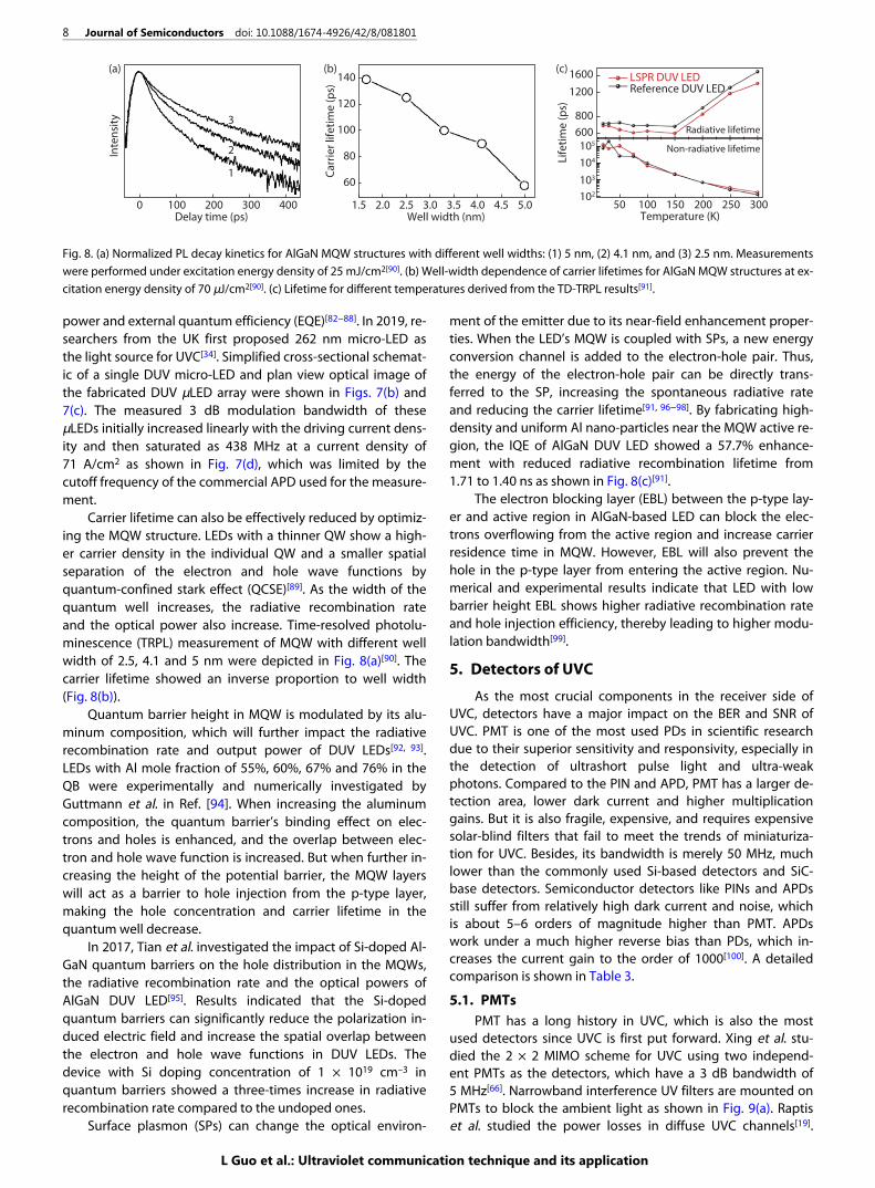
Carrier lifetime can also be effectively reduced by optimiz-ing the MQW structure. LEDs with a thinner QW show a high-er carrier density in the individual QW and a smaller spatialseparation of the electron and hole wave functions byquantum-confined stark effect (QCSE)[89]. As the width of thequantum well increases, the radiative recombination rateand the optical power also increase. Time-resolved photolu-minescence (TRPL) measurement of MQW with different wellwidth of 2.5, 4.1 and 5 nm were depicted in Fig. 8(a)[90]. Thecarrier lifetime showed an inverse proportion to well width(Fig. 8(b)).
Quantum barrier height in MQW is modulated by its alu-minum composition, which will further impact the radiativerecombination rate and output power of DUV LEDs[92, 93].LEDs with Al mole fraction of 55%, 60%, 67% and 76% in theQB were experimentally and numerically investigated byGuttmann et al. in Ref. [94]. When increasing the aluminumcomposition, the quantum barrier’s binding effect on elec-trons and holes is enhanced, and the overlap between elec-tron and hole wave function is increased. But when further in-creasing the height of the potential barrier, the MQW layerswill act as a barrier to hole injection from the p-type layer,making the hole concentration and carrier lifetime in thequantum well decrease.
In 2017, Tian et al. investigated the impact of Si-doped Al-GaN quantum barriers on the hole distribution in the MQWs,the radiative recombination rate and the optical powers ofAlGaN DUV LED[95]. Results indicated that the Si-dopedquantum barriers can significantly reduce the polarization in-duced electric field and increase the spatial overlap betweenthe electron and hole wave functions in DUV LEDs. Thedevice with Si doping concentration of 1 × 1019 cm–3 inquantum barriers showed a three-times increase in radiativerecombination rate compared to the undoped ones.
Surface plasmon (SPs) can change the optical environ-
ment of the emitter due to its near-field enhancement proper-ties. When the LED’s MQW is coupled with SPs, a new energyconversion channel is added to the electron-hole pair. Thus,the energy of the electron-hole pair can be directly trans-ferred to the SP, increasing the spontaneous radiative rateand reducing the carrier lifetime[91, 96−98]. By fabricating high-density and uniform Al nano-particles near the MQW active re-gion, the IQE of AlGaN DUV LED showed a 57.7% enhance-ment with reduced radiative recombination lifetime from1.71 to 1.40 ns as shown in Fig. 8(c)[91].
The electron blocking layer (EBL) between the p-type lay-er and active region in AlGaN-based LED can block the elec-trons overflowing from the active region and increase carrierresidence time in MQW. However, EBL will also prevent thehole in the p-type layer from entering the active region. Nu-merical and experimental results indicate that LED with lowbarrier height EBL shows higher radiative recombination rateand hole injection efficiency, thereby leading to higher modu-lation bandwidth[99].
5. Detectors of UVC
As the most crucial components in the receiver side ofUVC, detectors have a major impact on the BER and SNR ofUVC. PMT is one of the most used PDs in scientific researchdue to their superior sensitivity and responsivity, especially inthe detection of ultrashort pulse light and ultra-weakphotons. Compared to the PIN and APD, PMT has a larger de-tection area, lower dark current and higher multiplicationgains. But it is also fragile, expensive, and requires expensivesolar-blind filters that fail to meet the trends of miniaturiza-tion for UVC. Besides, its bandwidth is merely 50 MHz, muchlower than the commonly used Si-based detectors and SiC-base detectors. Semiconductor detectors like PINs and APDsstill suffer from relatively high dark current and noise, whichis about 5–6 orders of magnitude higher than PMT. APDswork under a much higher reverse bias than PDs, which in-creases the current gain to the order of 1000[100]. A detailedcomparison is shown in Table 3.
5.1. PMTs
PMT has a long history in UVC, which is also the mostused detectors since UVC is first put forward. Xing et al. stu-died the 2 × 2 MIMO scheme for UVC using two independ-ent PMTs as the detectors, which have a 3 dB bandwidth of5 MHz[66]. Narrowband interference UV filters are mounted onPMTs to block the ambient light as shown in Fig. 9(a). Raptiset al. studied the power losses in diffuse UVC channels[19].
Inte
nsity
Delay time (ps) Well width (nm)0 100 200 300
3
2
1
400
140
120
100
Carr
ier l
ifetim
e (p
s)
Life
time
(ps)
80
60
1.5 2.0 2.5 3.0 3.5 4.0 4.5 5.0 50 100 150 200Temperature (K)
Radiative lifetime
Non-radiative lifetime
250 300
(a) (b) (c)
600
102
103
104
105
800
16001200
LSPR DUV LEDReference DUV LED
Fig. 8. (a) Normalized PL decay kinetics for AlGaN MQW structures with different well widths: (1) 5 nm, (2) 4.1 nm, and (3) 2.5 nm. Measurementswere performed under excitation energy density of 25 mJ/cm2[90]. (b) Well-width dependence of carrier lifetimes for AlGaN MQW structures at ex-citation energy density of 70 μJ/cm2[90]. (c) Lifetime for different temperatures derived from the TD-TRPL results[91].
8 Journal of Semiconductors doi: 10.1088/1674-4926/42/8/081801
L Guo et al.: Ultraviolet communication technique and its application

The receiver consisted of a PMT (with a responsivity of0.06 A/W at 265 nm). A large set of measurements at dis-tances up to 20 m, for different elevation angles of the trans-mitter (UV-LEDs) and receiver (PMT) and for different atmo-spheric conditions have been taken for the characterizationof the UVC channel in terms of path loss. The experimentsetup is shown in Fig. 9(b). Meng et al. built up a four-receiv-er real-time platform and explored the characteristics and ef-fectiveness of diversity reception in single-input-multiple-out-put (SIMO) UVC system with a four-PMT-detector array[30].Each pair of PMTs was transversely separated by 150 mm asshown in Fig. 9(c). The experimental results for 1 × 4 SIMOUVC system showed that with a smaller Tx elevation or short-er distance, equal gain combining (EGC) may produce a di-versity gain in the UV channel and thus improve the BER per-formance at low transmitter power.
5.2. Semiconductor PDs
Recently, the commercially available Si and SiC-basedPINs and APDs have been replacing PMT in more and morescenarios. SiC-based PD shows excellent UV responsivity char-acteristics and a very low dark current between 200 and400 nm. The responsivity at 270 nm is between 150 and175 mA/W with a quantum efficiency of between 70% and
85%[103]. Several groups have reported UVC links using SiAPD for UV detection[34, 64]. The reported detector has awavelength range of 200–1000 nm, bandwidth of 400 MHz, re-sponsivity of 15 A/W and an active area diameter of 0.2 mm.Kojima et al. used a 1 GHz Si-based APD with 30 kV/W respons-ibility at 250 nm in UVC link[35, 62].
AlGaN-based APDs are intrinsically solar-blind with no ad-ditional filters required and are an ideal alternative to cur-rent bulky and fragile PMTs. In 2014, Shao et al. reported anAlGaN-based APD with a record-high gain of 1.2 × 10⁴ and apeak responsivity of 0.15 A/W around 280 nm[104]. The absorp-tion and multiplication zone were separated by a 60 nm n-type Al0.4Ga0.6N layer and thus yielded higher gain and lowernoise than the regular APD.
5.3. Potential detectors for UVC
Recently, solar-blind detectors with novel material anddevice structure have been proposed extensively, amongwhich Ga2O3, ZnO-Ga2O3 and MgZnO based detectors haveshown great potential in replacing the current solar-blind de-tectors for UVC. With its wide bandgap of 4.9 eV, Ga2O3-based PDs are perfectly fit for solar-blind detection inUVC[105−107]. Hu et al. fabricated Au-Ga2O3-Au based solar-
Table 3. Comparison of DUV detectors in UVC system.
Detector Spectral range (nm) Responsivity (A/W) Response time (ns) Dark current (nA) Ref
PMT 110–1100 ~105 1–15 2–30 [101]SiC PIN 200–400 0.085–0.13 ~10 3 × 10⁻⁸
Si PIN 200–1100 ~0.38 6–50 ~10AlGaN PIN 220–280 ~0.15 ~6.5 [102]Si APD 260–1100 0.24–0.5 ~3 × 10⁶ 1–100
Receiverosilloscope
(a) (c)
(b)
PMTsPN squence
Duty cyclingFPGA
LED driving circuit
A/D
EGC & Smooth �ltering
Recovery & Decision
BED output
FPGA
Lock-in detection
Sine generation
Currentdriver
Baseline distance r
TIA
OscilloscopePC
Electrical part ofthe transmitter
A/D A/D
Electrical part of the receiver
PMT + �lterRXθRXθTX
φTX φRX
TX
4 SETi LEDs
Fig. 9. (Color online) (a) The experimental setup of the receiver side[66]. (b) The experimental setup[19]. (c) Experimental setup for solar-blind NLOSUV communication with diversity reception[30].
Journal of Semiconductors doi: 10.1088/1674-4926/42/8/081801 9
L Guo et al.: Ultraviolet communication technique and its application

blind PDs which showed a maximum responsivity at around255 nm and a cutoff wavelength of 260 nm[108]. solar-blindPDs based on Ga2O3/SnO2 and Ga2O3/Si heterostructureswere also reported by Mahmoud and Guo in 2016[109, 110].
The lattice mismatch between ZnO and Ga2O3 is relat-ively small, making it easier to grow Ga2O3 on ZnO. And thelarge conduction band offsets between Ga2O3 and ZnOprompt large avalanche multiplication which leads to larger re-sponsivity. Zhao et al. proposed a single core-shell microwireAPDs based on ZnO–Ga2O3 heterostructure[111]. The pro-posed APDs with peak responsivity of 1.3 × 10³ A/W, detectiv-ity of 9.91 × 1014 cm·Hz1/2/W and response time of 20 μs un-der –6 V bias exhibited excellent photo-response perform-ances compared to commercial Si-based APDs.
MgZnO is another promising candidate for solar-blindPDs. Theoretically, the bandgap of MgZnO can be tuned from3.4 to 7.8 eV by changing the Mg content. But the fabrica-tion technique for MgZnO is still in its infancy due to thelarge mismatch between the MgZnO epilayer and its com-mon substrates. Du et al. first proposed MgZnO-based solar-blind PDs in 2009[112]. Since then, more and more groupshave participated in this area. In 2016, Alema et al. achieveda record high responsivity of ~1.8 × 10⁴ A/W at 276 nm un-der 10 V bias for MgZnO-based solar-blind PDs[113]. This is at-tributed to the asymmetric barrier height at the two sides ofthe MSM (metal–semiconductor–metal) electrodes whichgave rise to the carrier trapping states at the MgZnO/Ni/Au in-terface.
6. Future application of UVC
UVC has a lot of potential applications in underwater com-munication, vehicular communication and machine-to-ma-chine communication. The frequency band used in UVC ismuch higher than that of radio frequency (RF) communica-tion, so traditional electromagnetic interference (EMI) tech-nology and signal interception technology cannot be ap-plied to UVC, guarenteeing confidential and interference-freecommunication environment for UVC. We present some scen-arios where UVC can be a viable alternative to conventionalcommunication.
6.1. Battlefield applications
On the battlefield, radio sometimes needs to be turnedoff to conceal operation. Under this circumstance, gestures orcode words will usually be used for short-range communica-tion. By using UVC as the alternative, unicast, multicast andbroadcast communications will be possible. Short-range com-munication in conventional tactical operations usually re-quires cable, but the cable set-up requires extra time severelyrestraining the speed and maneuverability of operation.While UVC systems can be quickly set up with no cable re-quired.
6.2. Aircraft guidance system
UVC can also be used in take-off guidance systemsamong control towers, aircraft carriers and aircraft[114]. Trans-mitters can be mounted on the bridge of the aircraft carrierto radiate UV light signals horizontally to the deck, and eachaircraft is equipped with a small receiver to collect guidancesignals distributed in the air. The light signal from the transmit-ters can illuminate the entire flight deck so that the aircraft
can move freely and receive signals simultaneously.
6.3. Aircraft squad communication
UVC systems can be used for confidential communica-tions among aircraft squad as shown in Fig. 10. In this case,each aircraft is equipped with a transceiver system. The trans-mitter radiates light signals in a horizontal direction and thereceiver is mounted facing the sky to collect UV signalsscattered into its FOV to build electromagnetically silent andsecure internal communications.
7. Conclusion and outlook of UVC
In this article, we summarize and describe the historyand working principle of UVC. A comprehensive comparisonof its light sources and detectors is provided to the best ofour knowledge. Then we discuss the research progress ofUVC from a device perspective. For light sources, our reviewis based on three of the most used UV light sources includ-ing gas discharge lamp, laser and LED. For detectors, otherthan the commonly used detectors including PMTs and semi-conductor PDs, we also discuss some potential solar-blind de-tectors for UVC. Finally, we present the application and out-look of UVC. Hopefully, this review will offer valuable in-sights into the future development of UVC.
As a novel optical communication, UVC shows great pote-ntial in replacing conventional communication. Rich theoryon the networking, channel model, modulation scheme andsignal processing have been put forward and verified experi-mentally[4, 115, 116]. However, light sources and detectors stillare the two bottlenecks restricting UVC’s wide application.With high security, high stability, low power loss and shortresponse time, AlGaN-based LEDs have been considered asone of the most ideal light sources for UVC[117, 118]. However,the research on its bandwidth is still in its infancy. How to im-prove the bandwidth of DUV LEDs in terms of materialgrowth, device structure, manufacturing process and pack-aging is still an open question. PMT has gradually been re-placed by its cheap and efficient counterparts like PINs andAPDs in UVC. But solar-blind PINs and APDs still suffer from rel-atively high dark current and low responsivity. Improvementin fabrication techniques and device structures is expected toresolve these issues.
Acknowledgements
This work was financially supported by the National Key
Fig. 10. Application of UVC in aircraft squad.
10 Journal of Semiconductors doi: 10.1088/1674-4926/42/8/081801
L Guo et al.: Ultraviolet communication technique and its application

R&D Program of China (No. 2019YFA0708203), the NationalNatural Science Foundation of China (No. 61974139), and theBeijing Natural Science Foundation (No. 4182063).
References
Khalighi M A, Uysal M. Survey on free space optical communica-tion: A communication theory perspective. IEEE Commun SurvTutor, 2014, 16(4), 2231
[1]
Rajbhandari S, McKendry J J, Herrnsdorf J, et al. A review of gal-lium nitride LEDs for multi-gigabit-per-second visible light datacommunications. Semicond Sci Technol, 2017, 32(2), 023001
[2]
Shaw G A, Nischan M L, Iyengar M A, et al. NLOS UV communica-tion for distributed sensor systems. International Symposium onOptical Science and Technology, 2000, 83
[3]
Xu Z, Sadler B M. Ultraviolet communications: potential andstate-of-the-art. IEEE Commun Mag, 2008, 46(5), 67
[4]
Harvey G. A survey of ultraviolet communication systems. Wash-ington: Naval Research Laboratory, 1964
[5]
White H. Communication by non-visible ultraviolet radiation.Berkeley: University of California Press, 1945
[6]
Sunstein D E. A scatter communications link at ultraviolet fre-quencies. PhD Dissertation, Massachusetts Institute of Techno-logy, 1968
[7]
Charles B, Hughes B, Erickson A, et al. Ultraviolet laser-based com-munication system for short-range tactical applications.OE/LASE '94, 1994, 79
[8]
Shaw G A, Siegel A M, Model J, et al. Field testing and evalu-ation of a solar-blind UV communication link for unattendedground sensors. Defense and Security, 2004, 250
[9]
Shaw G A, Siegel A M, Model J. Extending the range and perform-ance of non-line-of-sight ultraviolet communication links. De-fense and Security Symposium, 2006, 62310C
[10]
Xu Z, Tsatsanis M K. Blind adaptive algorithms for minimum vari-ance CDMA receivers. IEEE Trans Commun, 2001, 49(1), 180
[11]
Xu Z, Chen G, Abou-Galala F, et al. Experimental performanceevaluation of non-line-of-sight ultraviolet communication sys-tems. Optical Engineering + Applications, 2007, 67090Y
[12]
Xu Z, Ding H, Sadler B M, et al. Analytical performance study ofsolar blind non-line-of-sight ultraviolet short-range communica-tion links. Opt Lett, 2008, 33(16), 1860
[13]
Liu L D, Ni G Q, Zhong S D, et al. Application and detection of ul-traviolet and their new development. Opt Technol, 1998, 2, 87(in Chinese)
[14]
Ni G Q. Study on ultraviolet communication through disen-gaged atmodphere. Opt Tech, 2000, 26, 297 (in Chinese)
[15]
Tang Y, Ni G, Zhang L, et al. Study of single scatter model inNLOS UV communication. Opt Tech, 2007, 33, 759 (in Chinese)
[16]
Tang Y, Wu Z L, Ni G Q, et al. NLOS single scattering model in di-gital UV communication. Asia-Pacific Opt Communi, 2008,713615
[17]
Kedar D, Arnon S. Subsea ultraviolet solar-blind broadband free-space optics communication. Opt Eng, 2009, 48(4), 046001
[18]
Raptis N, Pikasis E, Syvridis D. Power losses in diffuse ultravio-let optical communications channels. Opt Lett, 2016, 41(18),4421
[19]
Yin H, Chang S, Wang X, et al. Analytical model of non-line-of-sight single-scatter propagation. J Opt Soc Am A, 2010, 27(7),1505
[20]
Yin H, Chang S, Jia H, et al. Non-line-of-sight multiscatter propaga-tion model. J Opt Soc Am A, 2009, 26(11), 2466
[21]
Zhang H, Yin H, Jia H, et al. Study of effects of obstacle on non-line-of-sight ultraviolet communication links. Opt Express, 2011,19(22), 21216
[22]
Zhang H. Study on the characteristics of propagation of ultravi-[23]
olet communication system. PhD Dissertation, National Uni-versity of Defense Technology, 2012 (in Chinese)Yin H, Yang J, Chang S, et al. Analysis of several factors influen-cing range of non-line-of-sight UV transmission. Asia-Pacific Op-tical Communications, 2007, 67833E
[24]
Jia H, Huang H X, Zhang H. Influence factors on data speed ofwireless ultraviolet communication. Optics & OptoelectronicTechnology, 2010, 1, 20 (in Chinese)
[25]
Zuo Y, Xiao H, Wu J, et al. A single-scatter path loss model fornon-line-of-sight ultraviolet channels. Opt Express, 2012, 20(9),10359
[26]
Zuo Y, Wu Jian, Xiao H F, et al. Non-line-of-sight ultraviolet com-munication performance in atmospheric turbulence. ChinaCommun, 2013, 10(11), 52
[27]
Xiao H, Zuo Y, Wu J, et al. Non-line-of-sight ultraviolet single-scat-ter propagation model in random turbulent medium. Opt Lett,2013, 38(17), 3366
[28]
Guo L, Meng D, Liu K, et al. Experimental research on the MRC di-versity reception algorithm for UV communication. Appl Opt,2015, 54(16), 5050
[29]
Meng X, Zhang M, Han D, et al. Experimental study on 1× 4 real-time SIMO diversity reception scheme for a ultraviolet comm-unication system. European Conference on Networks and Optic-al Communications (NOC), 2015, 1
[30]
Sun Z, Zhang L, Qin Y, et al. 1 Mbps NLOS solar-blind ultravioletcommunication system based on UV-LED array. International Con-ference on Optical Instruments and Technology 2017, 2017,106170O
[31]
Sun X, Cai W, Alkhazragi O, et al. 375-nm ultraviolet-laser basednon-line-of-sight underwater optical communication. Opt Ex-press, 2018, 26(10), 12870
[32]
Sun X, Kong M, Alkhazragi O, et al. Non-line-of-sight methodo-logy for high-speed wireless optical communication in highly tur-bid water. Opt Commun, 2020, 461, 125264
[33]
He X, Xie E, Islim M S, et al. 1 Gbps free-space deep-ultravioletcommunications based on III-nitride micro-LEDs emitting at 262nm. Photonics Res, 2019, 7(7), B41
[34]
Kojima K, Yoshida Y, Shiraiwa M, et al. 1.6-Gbps LED-based ultravi-olet communication at 280 nm in direct sunlight. 2018European Conference on Optical Communication (ECOC), 2018,1
[35]
Laj P, Klausen J, Bilde M, et al. Measuring atmospheric composi-tion change. Atmos Environ, 2009, 43(33), 5351
[36]
Walter V, Saska M, Franchi A. Fast mutual relative localization ofuavs using ultraviolet led markers. 2018 International Confer-ence on Unmanned Aircraft Systems (ICUAS), 2018, 1217
[37]
Andrews D L. Rayleigh scattering and Raman effect, theory. In: En-cyclopedia of Spectroscopy and Spectrometry. Boston: Academ-ic Press, 2016
[38]
Swinehart D F. The beer-lambert law. J Chem Educ, 1962, 39(7),333
[39]
Luettgen M R, Shapiro J H, Reilly D M. Non-line-of-sight single-scatter propagation model. J Opt Soc Am A, 1991, 8(12), 1964
[40]
Sholtes K A, Lowe K, Walters G W, et al. Comparison of ultravi-olet light-emitting diodes and low-pressure mercury-arc lampsfor disinfection of water. Environ Technol, 2016, 37(17), 2183
[41]
Pousset T, Cussac P, Zissis G, et al. Electronic ballast for high-pres-sure mercury lamps. 1996 IEEE Industry Applications Society An-nual Meeting, 1996, 2109
[42]
Van Bommel W. Road lighting: Fundamentals, technology and ap-plication. Berlin: Springer, 2014
[43]
Ready J F. Industrial applications of lasers. Amsterdam: Elsevier,1997
[44]
Sun K X, Leindecker N, Higuchi S, et al. UV LED operation life-time and radiation hardness qualification for space flights. 7th In-ternational LISA Symposium, 2008, 012028
[45]
Journal of Semiconductors doi: 10.1088/1674-4926/42/8/081801 11
L Guo et al.: Ultraviolet communication technique and its application
Fishburne E, Neer M E, Sandri G. Voice communication viascattered ultraviolet radiation. New Jersey: Aeronautical Re-search Associates Of Princeton Inc, 1976
[46]
Geller M, Keenan T E, Altman D E, et al. Optical non-line-of-sightcovert, secure high data communication system. US Patents,US4493114, 1985
[47]
Puschell J J, Bayse R. High data rate ultraviolet communicationsystems for the tactical battlefield. Tactical CommunicationsConference, 1990, 253
[48]
Chen G, Xu Z, Sadler B M. Experimental demonstration of ultravi-olet pulse broadening in short-range non-line-of-sight commu-nication channels. Opt Express, 2010, 18(10), 10500
[49]
Wang K, Gong C, Zou D, et al. Demonstration of a 400 kbps real-time non-line-of-sight laser-based ultraviolet communication sys-tem over 500 m. Chin Opt Lett, 2017, 15(4), 040602
[50]
Liao L, Drost R J, Li Z, et al. Long-distance non-line-of-sight ultravi-olet communication channel analysis: experimentation and mod-elling. IET Optoelectron, 2015, 9(5), 223
[51]
Würtele M, Kolbe T, Lipsz M, et al. Application of GaN-based ultra-violet-C light emitting diodes – UV LEDs – for water disinfection.Water Res, 2011, 45(3), 1481
[52]
Siegel S B. Light emitting apparatus and method for curing inks,coatings and adhesives. US Patents, US7175712, 2007
[53]
Hirayama H. Research status and prospects of deep ultravioletdevices. J Semicond, 2019, 40(12), 120301
[54]
Barolet D. Light-emitting diodes (LEDs) in dermatology. SeminCutan Med Surg, 2008, 27(4), 227
[55]
Khan A, Balakrishnan K, Katona T. Ultraviolet light-emitting di-odes based on group three nitrides. Nat Photonics, 2008, 2(2),77
[56]
Kneissl M, Kolbe T, Chua C, et al. Advances in group III-nitride-based deep UV light-emitting diode technology. Semicond SciTechnol, 2010, 26(1), 014036
[57]
Li J, Ji G, Yang W, et al. Emission mechanism of high Al-contentAlGaN multiple quantum wells. Chin J Lumin, 2016, 37(5), 513(in Chinese)
[58]
Komine T, Nakagawa M. Fundamental analysis for visible-lightcommunication system using LED lights. IEEE Trans Consum Elec-tron, 2004, 50(1), 100
[59]
Alkhazragi O, Hu F, Zou P, et al. 2.4-Gbps ultraviolet-C solar-blind communication based on probabilistically shaped DMTmodulation. 2020 Optical Fiber Communication Conference,2020, M3I.5
[60]
Alkhazragi O, Hu F, Zou P, et al. Gbit/s ultraviolet-C diffuse-line-of-sight communication based on probabilistically shaped DMTand diversity reception. Opt Express, 2020, 28(7), 9111
[61]
Yoshida Y, Kojima K, Shiraiwa M, et al. An outdoor evaluation of1-Gbps optical wireless communication using AlGaN-based LEDin 280-nm band. 2019 Conference on Lasers and Electro-Optics(CLEO), 2019, 1
[62]
Yang Y, Chen X H, You B, et al. Design of solar blind ultravioletLED real-time video transmission system. Infrared Laser Eng,2018, 47, 1022001 (in Chinese)
[63]
Sun X, Zhang Z, Chaaban A, et al. 71-Mbit/s ultraviolet-B LED com-munication link based on 8-QAM-OFDM modulation. Opt Ex-press, 2017, 25(19), 23267
[64]
Qin H, Zuo Y, Li F, et al. Analytical link bandwidth model basedsquare array reception for non-line-of-sight ultraviolet communic-ation. Opt Express, 2017, 25(19), 22693
[65]
Xing Y, Zhang M, Han D, et al. Experimental study of a 2 × 2MIMO scheme for ultraviolet communications. 2016 15th Interna-tional Conference on Optical Communications and Networks(ICOCN), 2016, 1
[66]
Song P, Zhao T, Ke X, et al. Multi-user interference in a non-line-of-sight ultraviolet communication network. IET Commun, 2016,
[67]
10(13), 1640Zhang M, Luo P, Guo X, et al. Spread spectrum-based ultravioletcommunication with experiments. Chin Opt Lett, 2014, 12(10),100602
[68]
He Q, Xu Z, Sadler B M. Performance of short-range non-line-of-sight LED-based ultraviolet communication receivers. Opt Ex-press, 2010, 18(12), 12226
[69]
Chen G, Abou-Galala F, Xu Z, et al. Experimental evaluation ofLED-based solar blind NLOS communication links. Opt Express,2008, 16(19), 15059
[70]
Shi J W, Chen C C, Sheu J K, et al. Linear cascade GaN-basedgreen light-emitting diodes with invariant high-speed/powerperformance under high-temperature operation. IEEE PhotonTechnol Lett, 2008, 20(23), 1896
[71]
Shi J W, Sheu J K, Wang C K, et al. Linear cascade arrays of GaN-based green light-emitting diodes for high-speed and high-power performance. IEEE Photon Technol Lett, 2007, 19(18),1368
[72]
Shi J W, Sheu J K, Chen C H, et al. High-speed GaN-based greenlight-emitting diodes with partially n-doped active layers and cur-rent-confined apertures. IEEE Electron Device Lett, 2008, 29(2),158
[73]
McKendry J J, Green R P, Kelly A, et al. High-speed visible lightcommunications using individual pixels in a micro light-emit-ting diode array. IEEE Photon Technol Lett, 2010, 22(18), 1346
[74]
Huang Y, Guo Z, Huang H, et al. Influence of current density andcapacitance on the bandwidth of VLC LED. IEEE Photon TechnolLett, 2018, 30(9), 773
[75]
Zhu S C, Zhao L X, Yang C, et al. GaN-based flip-chip parallel mi-cro LED array for visible light communication. 2017 Internation-al Conference on Optoelectronics and Microelectronics Techno-logy and Application, 2016, 102441Y
[76]
McKendry J J, Massoubre D, Zhang S, et al. Visible-light commu-nications using a CMOS-controlled micro-light-emitting-diode ar-ray. J Light Technol, 2011, 30(1), 61
[77]
Ferreira R X, Xie E, McKendry J J, et al. High bandwidth GaN-based micro-LEDs for multi-Gb/s visible light communications.IEEE Photon Technol Lett, 2016, 28(19), 2023
[78]
Bai J, Cai Y, Feng P, et al. Ultra-small, ultra-compact and ultra-high efficient InGaN micro light emitting diodes (μLEDs) with nar-row spectral linewidth. ACS Nano, 2020, 14(6), 6909
[79]
Rashidi A, Monavarian M, Aragon A, et al. Nonpolar m-planeInGaN/GaN micro-scale light-emitting diode with 1.5 GHz modu-lation bandwidth. IEEE Electron Device Lett, 2018, 39(4), 520
[80]
Ploch N L, Rodriguez H, Stolmacker C, et al. Effective thermal man-agement in ultraviolet light-emitting diodes with micro-LED ar-rays. IEEE Trans Electron Devices, 2013, 60(2), 782
[81]
Zhang J, Wu S, Rai S, et al. AlGaN multiple-quantum-well-based,deep ultraviolet light-emitting diodes with significantly re-duced long-wave emission. Appl Phys Lett, 2003, 83(17), 3456
[82]
Hwang S, Islam M, Zhang B, et al. A hybrid micro-pixel baseddeep ultraviolet light-emitting diode lamp. Appl Phys Express,2010, 4(1), 012102
[83]
Wu S, Chhajed S, Yan L, et al. Matrix addressable micro-pixel 280nm deep UV light-emitting diodes. Jpn J Appl Phys, 2006,45(4L), L352
[84]
Adivarahan V, Wu S, Sun W, et al. High-power deep ultravioletlight-emitting diodes basedon a micro-pixel design. Appl PhysLett, 2004, 85(10), 1838
[85]
Adivarahan V, Heidari A, Zhang B, et al. 280 nm deep ultravioletlight emitting diode lamp with an AlGaN multiple quantum wellactive region. Appl Phys Express, 2009, 2(10), 102101
[86]
Sun W, Adivarahan V, Shatalov M, et al. Continuous wave milli-watt power AlGaN light emitting diodes at 280 nm. Jpn J ApplPhys, 2004, 43(11A), L1419
[87]
12 Journal of Semiconductors doi: 10.1088/1674-4926/42/8/081801
L Guo et al.: Ultraviolet communication technique and its application

Wu S, Adivarahan V, Shatalov M, et al. Micro-pixel design milli-watt power 254 nm emission light emitting diodes. Jpn J ApplPhys, 2004, 43(8A), L1035
[88]
Zhu S, Lin S, Li J, et al. Influence of quantum confined Stark ef-fect and carrier localization effect on modulation bandwidth forGaN-based LEDs. Appl Phys Lett, 2017, 111(17), 171105
[89]
Mickevičius J, Tamulaitis G, Kuokštis E, et al. Well-width-depend-ent carrier lifetime in AlGaN∕ AlGaN quantum wells. Appl PhysLett, 2007, 90(13), 131907
[90]
Lee J W, Ha G, Park J, et al. AlGaN deep-ultraviolet light-emit-ting diodes with localized surface plasmon resonance by a high-density array of 40 nm Al nanoparticles. ACS Appl Mater Inter-faces, 2020, 12(32), 36339
[91]
Wang C, Chiou Y, Hsiang C, et al. Enhancement of optical perform-ance of near-UV nitride-based light emitting diodes with differ-ent aluminum composition barrier structure. Phys Status SolidiA, 2014, 211(8), 1769
[92]
Kajitani R, Kawasaki K, Takeuchi M. Barrier-height and well-width dependence of photoluminescence from AlGaN-basedquantum well structures for deep-UV emitters. Mater Sci Eng B,2007, 139(2/3), 186
[93]
Guttmann M, Höpfner J, Reich C, et al. Effect of quantum barriercomposition on electro-optical properties of AlGaN-based UVClight emitting diodes. Semicond Sci Technol, 2019, 34(8),085007
[94]
Tian K, Chen Q, Chu C, et al. Investigations on AlGaN-baseddeep-ultraviolet light-emitting diodes with Si-doped quantumbarriers of different doping concentrations. Phys Status SolidiRRL, 2018, 12(1), 1700346
[95]
Guo W, Xu H, Yang Z, et al. Performance enhancement of ultravi-olet light emitting diode incorporating Al nanohole arrays. Nano-technology, 2018, 29(45), 45LT01
[96]
Huang K, Gao N, Wang C, et al. Top-and bottom-emission-en-hanced electroluminescence of deep-UV light-emitting diodesinduced by localised surface plasmons. Sci Rep, 2014, 4(1),4380
[97]
Gao N, Huang K, Li J, et al. Surface-plasmon-enhanced deep-UVlight emitting diodes based on AlGaN multi-quantum wells. SciRep, 2012, 2(1), 816
[98]
Zhu S, Wang J, Yan J, et al. Influence of AlGaN electron blockinglayer on modulation bandwidth of GaN-based light emitting di-odes. ECS Solid State Lett, 2014, 3(3), R11
[99]
Kharraz O, Forsyth D. Performance comparisons between PINand APD photodetectors for use in optical communication sys-tems. Optik, 2013, 124(13), 1493
[100]
Photonics H. Photomultiplier tubes. Hamamatsu: HamamatsuPhotonics, 2000
[101]
Chen Y, Zhang Z, Jiang H, et al. The optimized growth of AlNtemplates for back-illuminated AlGaN-based solar-blind ultravi-olet photodetectors by MOCVD. J Mater Chem C, 2018, 6(18),4936
[102]
Brown D M, Downey E T, Ghezzo M, et al. Silicon carbide UV pho-todiodes. IEEE Trans Electron Devices, 1993, 40(2), 325
[103]
Shao Z G, Chen D J, Lu H, et al. High-gain AlGaN solar-blindavalanche photodiodes. IEEE Electron Device Lett, 2014, 35(3),372
[104]
Higashiwaki M, Sasaki K, Murakami H, et al. Recent progress inGa2O3 power devices. Semicond Sci Technol, 2016, 31(3),034001
[105]
Li W, Zhang X, Meng R, et al. Epitaxy of III-nitrides on β-Ga2O3
and its vertical structure LEDs. Micromachines, 2019, 10(5), 322[106]
Pearton S, Yang J, Cary IV P H, et al. A review of Ga2O3 materials,processing, and devices. Appl Phys Rev, 2018, 5(1), 011301
[107]
Hu G, Shan C, Zhang N, et al. High gain Ga2O3 solar-blind photo-detectors realized via a carrier multiplication process. Opt Ex-press, 2015, 23(10), 13554
[108]
Mahmoud W E. Solar blind avalanche photodetector based onthe cation exchange growth of β-Ga2O3/SnO2 bilayer heterostruc-ture thin film. Sol Energy Mater Sol Cells, 2016, 152, 65
[109]
Guo X, Hao N, Guo D, et al. β-Ga2O3/p-Si heterojunction solar-blind ultraviolet photodetector with enhanced photoelectric re-sponsivity. J Alloys Compd, 2016, 660, 136
[110]
Zhao B, Wang F, Chen H, et al. Solar-blind avalanche photodetect-or based on single ZnO–Ga2O3 core–shell microwire. Nano Lett,2015, 15(6), 3988
[111]
Du X, Mei Z, Liu Z, et al. Controlled growth of high-quality ZnO-based films and fabrication of visible-blind and solar-blind ultra-violet detectors. Adv Mater, 2009, 21(45), 4625
[112]
Alema F, Hertog B, Ledyaev O, et al. High responsivity solarblind photodetector based on high Mg content MgZnO filmgrown via pulsed metal organic chemical vapor deposition.Sens Actuator A, 2016, 249, 263
[113]
Lavigne C, Durand G, Roblin A. Ultraviolet light propagation un-der low visibility atmospheric conditions and its application to air-craft landing aid. Appl Opt, 2006, 45(36), 9140
[114]
Yuan R, Ma J. Review of ultraviolet non-line-of-sight communica-tion. China Commun, 2016, 13(6), 63
[115]
Vavoulas A, Sandalidis H G, Chatzidiamantis N D, et al. A surveyon ultraviolet C-band (UV-C) communications. IEEE CommunSurv Tutor, 2019, 21(3), 2111
[116]
Razeghi M. Deep ultraviolet light-emitting diodes and photode-tectors for UV communications. Integrated OptoelectronicDevices, 2005, 2005, 30
[117]
Li J M, Liu Z, Liu Z Q, et al. Advances and prospects in nitridesbased light-emitting-diodes. J Semicond, 2016, 37(6), 061001
[118]
Liang Guo is currently pursuing his M.S. de-gree in the Institute of Semiconductors,Chinese Academy of Sciences. He received hisB.S. degree in Materials Physics from Hefei Uni-versity of Technology in 2018. His researchmainly focuses on the fabrication of deep-UVLEDs for communications.
Tongbo Wei is currently a professor in Insti-tute of Semiconductors, Chinese Academy ofSciences. He received his doctoral degree in en-gineering from Chinese Academy of Sciencesin July 2007. His research interests focus onwide bandgap semiconductor materials anddevices, new micro-nano photoelectronicdevices, deep ultraviolet light emittingdevices, and nitride growth on two-dimension-al materials.
Journal of Semiconductors doi: 10.1088/1674-4926/42/8/081801 13
L Guo et al.: Ultraviolet communication technique and its application