UltraSPARC (TM) -I Emulation - Clemson Universitymark/464/ultrasparc.emulation.pdf · the goals,...
6
UltraSPARC TM -I Emulation James Gateley, Miriam Blatt, Dennis Chen, Scott Cooke, Piyush Desai, Manjunath Doreswamy, Mark Elgood, Gary Feierbach, Tim Goldsbury, Dale Greenley, Raju Joshi, Mike Khosraviani, Robert Kwong, Manish Motwani, Chitresh Narasimhaiah, Sam J. Nicolino Jr., Tooru Ozeki, Gary Peterson, Chris Salzmann, Nasser Shayesteh, Jeffrey Whitman and Pak Wong SPARC Technology, Sun Microsystems, Inc. 2550 Garcia Avenue, Mountain View, CA 94043 Abstract - The next generation UltraSPARC-I CPU represents a significant step forward in processor performance at the cost of increased design complexity. Added complexity increases the risks in achieving functionally correct first silicon. Existing design verification techniques were supplemented by applying emulation to obtain an early look at functionality. Discussed are the goals, methods and results of the UltraSPARC-I emulation. I. INTRODUCTION Emulation is a method of functionally implementing a logic design with performance several orders of magnitude faster than simulation for the purpose of design verification. Emula- tion requires the use of dynamically configured hardware in which to implement the design. Emulation differs from tradi- tional simulation in that the emulation hardware implements the functionality of the design while simulation is a general- ized program that models the functionality while executing on a general purpose host computer. Where simulation processes events sequentially, emulation operates in parallel, as will the final silicon, resulting in fast emulation speeds of approxi- mately 500 KHz. The UltraSPARC-I CPU from SPARC Technology, a divi- sion of Sun Microsystems, Inc., is a high-performance 64-bit V9 SPARC implementation 100% compatible with existing binaries [1][2][3][4][5][6]. It is a 4 way superscalar design using 9 functional units. Support for either tightly-coupled or loosely-coupled multiprocessing is provided. New VISual instructions provide outstanding performance for multi-media applications[7][8]. II. EMULATION GOALS On-time delivery of new processor designs to market is critical for SPARC Technology to maintain its advantage. Emulating a processor design provides a competitive advan- tage over those that do not emulate designs. When a product arrives within its market window, it has greater potential for revenue generation. The primary goal for processor emulation is to shorten the time-to-market for the design [9][10]. Emulation provides verification capabilities not available through any other tech- nology. Emulation provides five advantages that affect time- to-market: • Improves confidence in the design prior to tapeout. • May reduce the number of silicon iterations to arrive at the final design. • Shortens the time to bring-up the silicon testbed by having software debugged in emulation. • Provides advanced debug facilities to rapidly isolate any functional problems in the silicon. • Provides design re-verification prior to additional silicon iterations. Tapeout is the event in time when the design is released for silicon fabrication. Emulation improves pre-tapeout confi- dence in the functionality of the design by providing an early look at tests too complex to simulate, including: • Power-On-Self-Test (POST) and other diagnostics • Single-user and Multi-user Solaris operating system boot • OpenWindows and applications • Benchmarks, stress tests and random exerciser tools When emulation finds functional bugs in the processor design before tapeout, the quality of the resulting silicon is improved as the bug is corrected before silicon commitment. This reduces the number of silicon iterations to arrive at the final design. Emulation finds bugs that slipped through simu- lation testing that would otherwise be found during silicon debug. In a typical CPU project without emulation, system soft- ware testing is scheduled to complete by first silicon return. Though completely simulated, subtle problems may escape detection until silicon bring-up. With emulation, the system software development is accelerated to meet an earlier sched- ule for emulation bring-up. Software bugs found and fixed during emulation bring-up will not cost time during the silicon bring-up, thus, emulation creates a pretested environment for silicon. The emulation system provides the capability to probe any net within the design and obtain deep history traces of those 32nd ACM/IEEE Design Automation Conference Permission to copy without fee all or part of this material is granted, provided that the copies are not made or distributed for direct commercial advantage, the ACM copyright notice and the title of the publication and its date appear, and notice is given that copying is by permission of the Association for Computing Machinery. To copy otherwise, or to republish, requires a fee and/or specific permission. 1995 ACM 0-89791-756-1/95/0006 $3.50
Transcript of UltraSPARC (TM) -I Emulation - Clemson Universitymark/464/ultrasparc.emulation.pdf · the goals,...

UltraSPARCTM-I Emulation
James Gateley, Miriam Blatt, Dennis Chen, Scott Cooke, Piyush Desai, Manjunath Doreswamy,Mark Elgood, Gary Feierbach, Tim Goldsbury, Dale Greenley, Raju Joshi, Mike Khosraviani,Robert Kwong, Manish Motwani, Chitresh Narasimhaiah, Sam J. Nicolino Jr., Tooru Ozeki,
Gary Peterson, Chris Salzmann, Nasser Shayesteh, Jeffrey Whitman and Pak WongSPARC Technology, Sun Microsystems, Inc.
2550 Garcia Avenue, Mountain View, CA 94043
Abstract - The next generation UltraSPARC-I CPU representsa significant step forward in processor performance at the cost ofincreased design complexity. Added complexity increases therisks in achieving functionally correct first silicon. Existingdesign verification techniques were supplemented by applyingemulation to obtain an early look at functionality. Discussed arethe goals, methods and results of the UltraSPARC-I emulation.
I. INTRODUCTION
Emulation is a method of functionally implementing a logicdesign with performance several orders of magnitude fasterthan simulation for the purpose of design verification. Emula-tion requires the use of dynamically configured hardware inwhich to implement the design. Emulation differs from tradi-tional simulation in that the emulation hardware implementsthe functionality of the design while simulation is a general-ized program that models the functionality while executing ona general purpose host computer. Where simulation processesevents sequentially, emulation operates in parallel, as will thefinal silicon, resulting in fast emulation speeds of approxi-mately 500 KHz.
The UltraSPARC-I CPU from SPARC Technology, a divi-sion of Sun Microsystems, Inc., is a high-performance 64-bitV9 SPARC implementation 100% compatible with existingbinaries [1][2][3][4][5][6]. It is a 4 way superscalar designusing 9 functional units. Support for either tightly-coupled orloosely-coupled multiprocessing is provided. New VISualinstructions provide outstanding performance for multi-mediaapplications[7][8].
II. EMULATION GOALS
On-time delivery of new processor designs to market iscritical for SPARC Technology to maintain its advantage.Emulating a processor design provides a competitive advan-tage over those that do not emulate designs. When a productarrives within its market window, it has greater potential forrevenue generation.
The primary goal for processor emulation is to shorten thetime-to-market for the design [9][10]. Emulation providesverification capabilities not available through any other tech-nology. Emulation provides five advantages that affect time-to-market:
• Improves confidence in the design prior to tapeout.
• May reduce the number of silicon iterations to arrive at thefinal design.
• Shortens the time to bring-up the silicon testbed by havingsoftware debugged in emulation.
• Provides advanced debug facilities to rapidly isolate anyfunctional problems in the silicon.
• Provides design re-verification prior to additional siliconiterations.
Tapeout is the event in time when the design is released forsilicon fabrication. Emulation improves pre-tapeout confi-dence in the functionality of the design by providing an earlylook at tests too complex to simulate, including:
• Power-On-Self-Test (POST) and other diagnostics
• Single-user and Multi-user Solaris operating system boot
• OpenWindows and applications
• Benchmarks, stress tests and random exerciser tools
When emulation finds functional bugs in the processordesign before tapeout, the quality of the resulting silicon isimproved as the bug is corrected before silicon commitment.This reduces the number of silicon iterations to arrive at thefinal design. Emulation finds bugs that slipped through simu-lation testing that would otherwise be found during silicondebug.
In a typical CPU project without emulation, system soft-ware testing is scheduled to complete by first silicon return.Though completely simulated, subtle problems may escapedetection until silicon bring-up. With emulation, the systemsoftware development is accelerated to meet an earlier sched-ule for emulation bring-up. Software bugs found and fixedduring emulation bring-up will not cost time during the siliconbring-up, thus, emulation creates a pretested environment forsilicon.
The emulation system provides the capability to probe anynet within the design and obtain deep history traces of those
32nd ACM/IEEE Design Automation Conference Permission to copy without fee all or part of this material is granted, providedthat the copies are not made or distributed for direct commercial advantage,the ACM copyright notice and the title of the publication and its date appear,and notice is given that copying is by permission of the Association forComputing Machinery. To copy otherwise, or to republish, requires a feeand/or specific permission. 1995 ACM 0-89791-756-1/95/0006 $3.50

nets. As many as 1000 nets per emulation system can beprobed at one time. These advanced debugging facilities aid inthe rapid isolation of any functional problem discovered in thesilicon.
Design changes can be easily incorporated into the emula-tion database. If additional silicon iterations to include func-tionality changes are required, emulation provides significantdesign re-verification prior to tapeout.
III. EMULATION METHODOLOGY
The Emulation Methodology consists of four major phases:Pre-configuration, Configuration, Testbed, and In-CircuitEmulation (ICE). Fig. 1 shows the relationship betweenphases.
Pre-Configuration Preparation must be completed prior toan attempt at an emulation database configuration. This phasebrings together all of the necessary database control files,netlists, libraries, and other inputs.
The Full Chip Configuration step uses the vendor suppliedconfiguration software to create the downloadable emulationdatabase. This step takes the results of the Pre-ConfigurationPreparation phase and generates the bitstream necessary toprogram the emulation hardware.
Testbed Preparation includes the design, planning andimplementation of the physical environment that contains theemulation. This testbed environment must provide all neces-sary real world hardware interfaces and resources.
The In-Circuit Emulation Phase integrates the testbed andthe design emulation to deliver a system in which verificationand debug can occur.
A. Pre-Configuration Preparation
During Pre-Configuration Preparation, all inputs needed tosuccessfully complete the full design configuration are assem-bled and prepared for inclusion in the configuration step.Some key components and procedures are discussed in thefollowing subsections.
Leaf-Cell Library Translation. The UltraSPARC-I projectmade liberal use of custom leaf-cell libraries to representdesign elements. To increase the flexibility of the libraries forthe design team, several individual cell libraries were created.The custom library cells represent elements in terms of theCPU design primitive elements. For emulation, each elementmust be expressed in terms of primitives defined by the emu-lation vendor. Fortunately, a rather large set of emulationprimitive elements was available; well in excess of 2000 ele-ments. Using an automated flow to perform this mappinggreatly simplified the task and facilitated rapid updating of theemulation library to reflect the latest design library changes.
The emulation libraries must be verified to ensure that eachelement fully and accurately reflects the original functional
intent of the library designers. This verification is accom-plished by comparing the results of a simulation of the origi-nal libraries to the emulation of the new libraries under thesame stimuli. A second verification step for the emulationlibrary elements is implicitly performed during the block leveltesting described below.
Depending on design style, there can be problem areas foremulation within a leaf-cell library. These must be identifiedand modified. Possible problems include “Wire” logic (Wired-or, Wired-and, etc.) that must be replaced by appropriate com-binational gates, transistor specified elements that must beredesigned into gates, element simplification, and multipleidentical elements with different power levels that can bereduced to a single element (power levels are a circuit require-ment not an emulation requirement).
Although UltraSPARC-I exclusively used custom leaf-celllibraries, other projects may benefit from emulation vendorsupplied pretested libraries for many standard ASIC technolo-gies.
The result of this translation and verification is a set oflibraries in terms of emulation primitives available to supportnetlist configurations.
Design Netlists. Full Chip Configuration requires all neces-sary gate level netlists to be collected and presented to theconfiguration software. This can be easy on a small project,but a design such as UltraSPARC-I involves a large number ofindividual netlists that can be in a variety of standard netlistformats. The netlists originate from different team members(standard cell designers, datapath designers, megacell design-ers, etc.) and often use specialized libraries. All netlists mustbe in a format acceptable to the emulation vendor’s configura-tion software. Translations could be required and tools weredeveloped as needed by the emulation team.
Once netlists are gathered and translated into an appropriatestandard syntax, the semantics of the netlists can be reviewed.
Fig. 1. The Emulation Methodology consists of four major phases. Theconfiguration tasks usually overlap in time with the Testbed Preparation. Tosuccessfully go In-Circuit, all tasks must be completed.
Pre-ConfigurationPreparation
TestbedPreparation
Full-ChipConfiguration
In-CircuitEmulation

There are several possible problem areas where the originaldesign may not be optimally compatible with emulation tech-nology. These incompatibilities are resolved by redesign oremulation-local modifications to the netlists. Areas of concerninclude gated clocks, feed-thrus, and pre-charge logic.
The emulation hardware implements a clock distributionscheme where highly tuned “low-skew nets” are designed intothe emulation system. These low-skew nets ensure that allphysical areas of the emulation hardware see the clocks withminimal skew with respect to all other locations within thesystem. When a design clock is gated it can no longer berouted over these special low-skew nets but must be routedthrough the system as any other data portion of the design.This has two very negative effects: potential for Hold TimeViolations in the design, and costs gates plus pins to route theclock. Gated clocks are redesigned to either remove the gat-ing, or pull the gating to the root of the clock tree to allow useof low-skew nets “down-stream” from the point of gating. Thevendor supplied clocktree analysis procedure greatly aids inidentification of this situation. Changes to the clock tree willbe verified during Block Configuration described below.
The design team may provide gate level netlists containingports and wires to implement feed-thru paths to reflect thephysical layout of the chip. In a multi-system emulation, thepartitioning of the design is based on minimizing the inter-system connections while maximizing the capacity of eachsystem. It is very possible that the floorplanning of the emula-tion design is radically different from that of the real chip;unrelated design blocks may co-exist within a single systemwhile tightly related blocks may be split between systems forcapacity reasons. Since the feed-thrus are designed to reflectthe silicon floorplanning rather than the emulation floorplan,surprising results can occur. For example, consider a bus thatpasses from one block through its neighboring block to a des-tination block. What if the neighboring block is resident in adifferent system than the source or destination block? The buscould be routed via external cables from the source system tothe system containing the neighboring block, then routed viadifferent external cables to the system that contains the desti-nation block. In this example, a feed-thru forces a bus to routevia cables to an external emulation system just to satisfy thedesigned feed-thru. The solution is to flatten design feed-thrusso the emulation configuration sees only direct connectionsfrom source block to actual destination block.
Repeaters can lead to the same problems as feed-thrus.Since emulation does not make use of or need repeaterdevices, they should be flattened from the design for emula-tion.
Emulation does not support pre-charge logic, pass-thrulatches, or domino logic. They must be redesigned into a staticrepresentation. Such redesign requires careful verification toensure that the emulation static model produces a cycle accu-rate functional representation of the original logic.
Other possible netlist problem areas need to be identifiedand resolved before full chip configuration begins.
Megacells and Large Memory Array Megacells. Mega-cells (custom circuits) come in two basic flavors: those con-taining large memories and those that do not contain largememories. The general discussion on megacells applies toboth types while there are additional complications to largememory array megacells.
Gate level descriptions of megacells may not be availableearly enough in the project to start the emulation effort. How-ever, there must be an RTL level description of each megacellused for simulation. It may be necessary to create an emula-tion local gate level description for each megacell. These localgate models may ultimately replaced by the actual gate leveldescription from the design team.
Megacells often have creative internal clocking structuresthat cause problems for emulation (see discussion on low-skew nets above). Frequently, such creative clocking is relatedto scan control and can be removed or redesigned. Other cre-ative clocking issues must be reviewed and reimplemented foremulation.
Memory arrays are implemented in emulation using exter-nal Memory Emulation Modules (MEM cards). Megacellscontaining MEM arrays require the additional step of parti-tioning the design into a control portion and a memory portionthat maps to one or more MEM cards. Some amount of emula-tion specific logic may be needed to glue together the controlportion of the megacell to the MEM card array.
All the above reimplementation of the megacells must becarefully verified for cycle accurate functionality with respectto the original megacell.
Block Configuration & Quickwave. In previous sections,there have been several statements about verification of cer-tain modifications to ensure cycle accurate functionality withrespect to the original design. The method used to performthis verification is to apply simulation generated test vectorsto an emulation of the equivalent block of logic.
Before beginning to configure the entire chip, the emulationteam configures, in isolation, each individual design block andselected parts of the design hierarchy. Once configured foremulation, these individual chunks of logic are test vector ver-ified to ensure that the top level outputs from the logic arecycle accurate with respect to the simulation model.
Mismatches indicate a problem with the emulation model.This could be a bad library element, an incorrect netlist modi-fication, or an incorrectly redesigned megacell.
Verification at the block level provides early detection ofmodel problems. This provides faster turn-around whiledebugging any such problems and much greater confidence inthe overall emulation model of the design. Once all blockspass test vector verification, the full chip configuration begins.
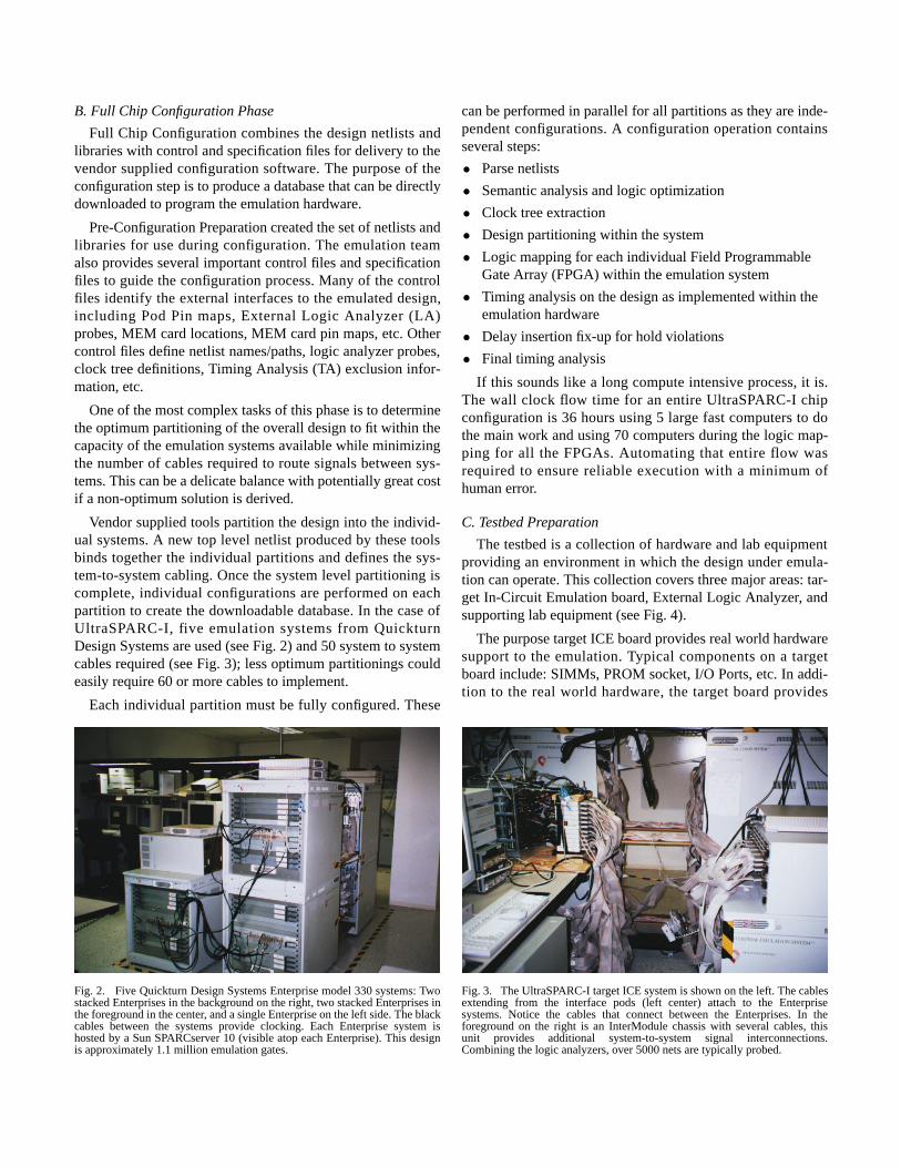
Fig. 3. The UltraSPARC-I target ICE system is shown on the left. The cablesextending from the interface pods (left center) attach to the Enterprisesystems. Notice the cables that connect between the Enterprises. In theforeground on the right is an InterModule chassis with several cables, thisunit provides additional system-to-system signal interconnections.Combining the logic analyzers, over 5000 nets are typically probed.
Fig. 2. Five Quickturn Design Systems Enterprise model 330 systems: Twostacked Enterprises in the background on the right, two stacked Enterprises inthe foreground in the center, and a single Enterprise on the left side. The blackcables between the systems provide clocking. Each Enterprise system ishosted by a Sun SPARCserver 10 (visible atop each Enterprise). This designis approximately 1.1 million emulation gates.
B. Full Chip Configuration Phase
Full Chip Configuration combines the design netlists andlibraries with control and specification files for delivery to thevendor supplied configuration software. The purpose of theconfiguration step is to produce a database that can be directlydownloaded to program the emulation hardware.
Pre-Configuration Preparation created the set of netlists andlibraries for use during configuration. The emulation teamalso provides several important control files and specificationfiles to guide the configuration process. Many of the controlfiles identify the external interfaces to the emulated design,including Pod Pin maps, External Logic Analyzer (LA)probes, MEM card locations, MEM card pin maps, etc. Othercontrol files define netlist names/paths, logic analyzer probes,clock tree definitions, Timing Analysis (TA) exclusion infor-mation, etc.
One of the most complex tasks of this phase is to determinethe optimum partitioning of the overall design to fit within thecapacity of the emulation systems available while minimizingthe number of cables required to route signals between sys-tems. This can be a delicate balance with potentially great costif a non-optimum solution is derived.
Vendor supplied tools partition the design into the individ-ual systems. A new top level netlist produced by these toolsbinds together the individual partitions and defines the sys-tem-to-system cabling. Once the system level partitioning iscomplete, individual configurations are performed on eachpartition to create the downloadable database. In the case ofUltraSPARC-I, five emulation systems from QuickturnDesign Systems are used (see Fig. 2) and 50 system to systemcables required (see Fig. 3); less optimum partitionings couldeasily require 60 or more cables to implement.
Each individual partition must be fully configured. These
can be performed in parallel for all partitions as they are inde-pendent configurations. A configuration operation containsseveral steps:
• Parse netlists
• Semantic analysis and logic optimization
• Clock tree extraction
• Design partitioning within the system
• Logic mapping for each individual Field ProgrammableGate Array (FPGA) within the emulation system
• Timing analysis on the design as implemented within theemulation hardware
• Delay insertion fix-up for hold violations
• Final timing analysis
If this sounds like a long compute intensive process, it is.The wall clock flow time for an entire UltraSPARC-I chipconfiguration is 36 hours using 5 large fast computers to dothe main work and using 70 computers during the logic map-ping for all the FPGAs. Automating that entire flow wasrequired to ensure reliable execution with a minimum ofhuman error.
C. Testbed Preparation
The testbed is a collection of hardware and lab equipmentproviding an environment in which the design under emula-tion can operate. This collection covers three major areas: tar-get In-Circuit Emulation board, External Logic Analyzer, andsupporting lab equipment (see Fig. 4).
The purpose target ICE board provides real world hardwaresupport to the emulation. Typical components on a targetboard include: SIMMs, PROM socket, I/O Ports, etc. In addi-tion to the real world hardware, the target board provides

Fig. 4. Closeup of the target ICE board and pods. The single PCB standingvertically in the chassis was custom designed for exclusive use by emulation.It provides access to memory SIMMs, I/O ports and supporting logic. On theright side are two columns of interface pods which pass signals between theemulation and the target board. External disk drives and pulse generators areon the extreme left.
sockets for emulation Pods that carry the top level I/O pinsfrom the emulated design. Care must be taken to plan thephysical and mechanical design requirements for the Podsincluding pod header spacing.
The target ICE board also provides headers to connect theexternal logic analyzer probes. These external probes supple-ment the visibility into the design provided by the internallogic analyzer inside of each emulation system. All totaled,over 5000 nets were routinely probed (128K depth) on theUltraSPARC-I project. A complete strategy for integrating theinternal emulation logic analyzer samples with external logicanalyzer samples was developed by the emulation team.
In addition to the target ICE board and emulation equip-ment, other basic lab equipment is necessary: pulse genera-tors, oscillascope, etc. Other important lab issues must beconsidered including physical setup, electrical requirementsand air conditioning.
D. In-Circuit Emulation Phase
The In-Circuit Emulation Phase combines the design emu-lation database with the testbed (target board and emulationhardware) to perform design verification. In addition, criticalsoftware must be available at ICE power-on. The emulationproject must coordinate with and ensure that PROMs andSoftware deliveries are adjusted to fit emulation scheduleswhich are earlier than silicon schedules.
The lab debug and bring-up effort requires a broad range ofknowledge and skills. A team of people must be identified toprovide this debug expertise during the bringup.
With the integration of the testbed hardware, emulationhardware, design emulation database and software, the designis downloaded into the emulation hardware, reset is releasedand it just boots Solaris--easy, right!? Unfortunately, like any
significant hardware bring-up, every part has to be systemati-cally debugged and fixed where needed. After a long (andoften painful) bring-up experience, the Solaris “login” promptappears on the monitor.
IV. EMULATION RESULTS
During the life of an emulation project there are three dis-tinct phases during which value is returned: pre-tapeout, post-tapeout to pre-silicon, and post-silicon. These phases alignwith the silicon events of first tapeout and first silicon returnsfrom the foundry. During each phase, emulation plays aslightly different role.
Based on past experience with the MicroSPARC II andSuperSPARC II processor emulation projects, a relative valuefor each of the phases was derived. Experience shows only25% of the total return on emulation investment is derivedduring the pre-tapeout phase with the remaining 75% valuereturned later in the project. All three phases have significantimpact on the ultimate delivery of the product to market.
A. Pre-Tapeout Phase
The pre-tapeout phase provides about 25% of the overallreturn on investment for an emulation project. The mainsource of value is in the additional functional design verifica-tion that can be completed by the emulation testbed prior totapeout.
The testbed for UltraSPARC-I successfully emulated thechip at execution speeds of several hundred kilohertz--manyorders of magnitude faster than simulation in terms of instruc-tion cycles per wall clock second. This makes it practical toboot single-user Solaris in about 1 hour and 30 minutes.
Prior to tapeout, UltraSPARC-I successfully booted single-user Solaris with all CPU features enabled.
During the bring-up of Solaris on the emulated UltraS-PARC-I, one serious design bug was encountered that pre-vented successful booting. Through the enhanced visibilityinto the design provided by emulation, this problem was iso-lated to a simple code sequence that under the right circum-stances caused a major problem. This problem was recreatedin simulation. A design fix was made and verified in both sim-ulation and emulation.
In addition to the UltraSPARC-I bug, a significant numberof bugs were found and fixed in the POST (Power-On Self-Test), boot PROM and kernel. These bug fixes were rolledforward into the silicon bring-up saving significant debugtime.
B. Post-Tapeout to Pre-Silicon Phase
The window of time between tapeout and silicon returnprovides an opportunity to continue the emulation effort andincrease the overall return on investment. This phase contrib-utes another 25% to the overall return.

During this short window of time the emulation teamfocuses on additional design verification via stress testing.Efforts during this phase on UltraSPARC-I focused on Multi-User Solaris and OpenWindows in addition to a large assort-ment of applications and stress tests.
If additional problems are found during this phase, smallfixes in the metal masks will improve the overall quality of thefirst silicon. No problems were discovered during this phasefor UltraSPARC-I.
C. Post-Silicon Phase
Following silicon return, emulation takes on a supportingrole. When a functional problem is encountered in silicon,emulation may prove to be a more friendly environment inwhich to debug with the available internal visibility into thedesign via the logic analyzer. Once a bug has been isolatedand a fix developed by the design team, emulation includesthe fix in the database and verifies that the problem has beenresolved. A suite of regression tests helps to insure that newproblems have not been introduced. Approximately 50% ofthe total return on investment is derived in this phase.
During this phase emulation can provide two additional ser-vices: what-if experiments and support for follow-on tapeoutverification.
Designers often want to try some design change orenhancements to see what effect it will have on the real sys-tem. Prototyping such what-if changes is relatively easy foremulation.
Just as with the first tapeout, the design team desires confi-dence in the design for any follow-on tapeout events (metal-mask changes, all layers changes, major design revision, etc.).The emulation provides additional confidence in each updateddesign by booting Solaris and running the suite of regressiontests.
V. BENEFITS
Emulation supplements existing design verification tech-niques providing additional capabilities not available throughany other technology. Confidence in the design prior to siliconcommitment is improved due to the additional verificationaccomplished by emulation. Applications can be executed in
emulation that are impractical to simulate due to executionduration. Problems discovered and fixed before tapeoutimprove the quality of the first silicon with a potential to savesilicon iterations.
Once silicon is available, bring-up benefits from the pre-tested software environment available as a result of emulationtesting. The advanced debugging capabilities in emulationreduce the time necessary to isolate functional design bugs.Design fixes and changes are rapidly prototyped in the emula-tion system before silicon commitment.
Emulation helps reduce the time-to-market of the completeproduct increasing life-time revenue and profit potential.
REFERENCES
[1] D. Greenley,et. al., "UltraSPARC: The Next GenerationSuperscalar 64 bit SPARC", 40th annual Compcon, 1995.
[2] Larry Yang, "System design methodology of UltraS-PARC", 32nd Design Automation Conference Proceed-ings (in press).
[3] Ariel Cao,et. al., "CAD Methodology for the Design ofUltraSPARC Microprocessor at Sun", 32nd Design Auto-mation Conference Proceedings (in press).
[4] Marc Tremblay, "A fast and flexible performance simula-tor for microarchitecture trade-off analysis on UltraS-PARC" , 32nd Des ign Au tomat ion Confe renceProceedings (in press).
[5] S. Mehta,et. al., "Verification of the UltraSPARC Micro-processor", 40th annual Compcon, 1995.
[6] Palnitkar, Saggurati “Finite State Machine Coverage pro-gram” Open Verilog International Conf. 1994.
[7] L. Kohn, et. al.,"The Visual Instruction Set (VIS) inUltraSPARC", 40th annual Compcon, 1995.
[8] C. Zhou,et. al., "MPEG Video Decoding with UltraS-PARC Visual instruction Set", 40th annual Compcon,1995.
[9] James Gateley, "Logic emulation aids design process",ASIC & EDA, July 1994.
[10] James Gateley, Miriam Blatt, "Reducing time-to-emula-tion through flow automation", Nikkei Electronics (inpress).