ULTRASONIC POLISHING - NASA · PDF fileULTRASONIC POLISHING Randy Gilmore Extrude Hone...
11
ULTRASONIC POLISHING Randy Gilmore Extrude Hone Corporation 8075 Pennsylvania Avenue Irwin, PA 15642 ABSTRACT me iu%trasonic polishing process uses high-frequency (ultrasonic) vibrations of an abradable tool wl~ic"natomaticallyconforms to the workpiece, and an abrasive sluny to finish surfaces and edges on comple:r, highly detailed, close tolerance cavities in materials from beryllium copper to carbide. Applscarions range from critical debuning of guidance system components to removing EDM recast layers 65m aircraft engine components to polishing molds for forming carbide cutting tool inserts or injection molding plastics. A variety of materials including tool steels, carbides and even ceramics can be successfully processed. Since the abradable tool automatically conforms to the workpiece geometry, the ui~azsoriic finishing method described offers a number of important benefits in finishing components with coxnp8ex geomelries. INTRODUCTION The automatic finishing of edges and surfaces of complex detailed geometries on critical cavities remarlas one of manufacturing's most important challenges. Finishing of molds and die cavities accounts for nnorc than one hundred million dollars annually, primarily in hand finishing by the most skilled mold makers. Finishing edges and surfaces of critical components for such devices as medical implants or inertial gagdance gyro systems is equally time consuming. When these component geometries provide through- flcw area.$, abrasive flow machining can often be used-but geometries with blind cavitics are not applicable or require difficult tooling. These components must be free from burrs or "smeared metal" nndcr 20 to 50 power magnification inspection. Uraiform removal of unwanted surface layers (such as thermal recast from EDM or laser machining, layers siaspccted of intergranular attack, "white layers," or oxidation) selectively without masking and without losing desired detail or tolerances is another problem for manufacturers, labored over with hand work and somelimes resulting in scrap or compromised designs. In the process of developing the ultrasonic machining process over the past several years for the purpose of machining brittle materials such as glass and graphite, it was discovered that by using a tool marerial that was easily abradable in ultrasonic machining-such as glass or graphite-the tool would rmcipfy shape itself to the workpiece providing a near perfect "mirror-image" conjugal form and thereby provading a uniform machining gap for ultrasonic machining. The result was that although the tool was being ' machined" much faster than the workpiece (in fact, because of this) the work performed on the workpncce was uniform. Whether the objective was to polish, remove a surface layer, or deburr and lightly radm the edges, the uniformity and gentleness of the work performed retained the detail and close tolerances https://ntrs.nasa.gov/search.jsp?R=19930016391 2018-05-22T12:08:21+00:00Z
Transcript of ULTRASONIC POLISHING - NASA · PDF fileULTRASONIC POLISHING Randy Gilmore Extrude Hone...

ULTRASONIC POLISHING
Randy Gilmore Extrude Hone Corporation 8075 Pennsylvania Avenue
Irwin, PA 15642
ABSTRACT
me iu%trasonic polishing process uses high-frequency (ultrasonic) vibrations of an abradable tool wl~ic"natomatically conforms to the workpiece, and an abrasive sluny to finish surfaces and edges on comple:r, highly detailed, close tolerance cavities in materials from beryllium copper to carbide. Applscarions range from critical debuning of guidance system components to removing EDM recast layers 65m aircraft engine components to polishing molds for forming carbide cutting tool inserts or injection molding plastics. A variety of materials including tool steels, carbides and even ceramics can be successfully processed. Since the abradable tool automatically conforms to the workpiece geometry, the ui~azsoriic finishing method described offers a number of important benefits in finishing components with coxnp8ex geomelries.
INTRODUCTION
The automatic finishing of edges and surfaces of complex detailed geometries on critical cavities remarlas one of manufacturing's most important challenges. Finishing of molds and die cavities accounts for nnorc than one hundred million dollars annually, primarily in hand finishing by the most skilled mold makers.
Finishing edges and surfaces of critical components for such devices as medical implants or inertial gagdance gyro systems is equally time consuming. When these component geometries provide through- flcw area.$, abrasive flow machining can often be used-but geometries with blind cavitics are not applicable or require difficult tooling. These components must be free from burrs or "smeared metal" nndcr 20 to 50 power magnification inspection.
Uraiform removal of unwanted surface layers (such as thermal recast from EDM or laser machining, layers siaspccted of intergranular attack, "white layers," or oxidation) selectively without masking and without losing desired detail or tolerances is another problem for manufacturers, labored over with hand work and somelimes resulting in scrap or compromised designs.
In the process of developing the ultrasonic machining process over the past several years for the purpose of machining brittle materials such as glass and graphite, it was discovered that by using a tool marerial that was easily abradable in ultrasonic machining-such as glass or graphite-the tool would rmcipfy shape itself to the workpiece providing a near perfect "mirror-image" conjugal form and thereby provading a uniform machining gap for ultrasonic machining. The result was that although the tool was being ' machined" much faster than the workpiece (in fact, because of this) the work performed on the workpncce was uniform. Whether the objective was to polish, remove a surface layer, or deburr and lightly radm the edges, the uniformity and gentleness of the work performed retained the detail and close tolerances
https://ntrs.nasa.gov/search.jsp?R=19930016391 2018-05-22T12:08:21+00:00Z
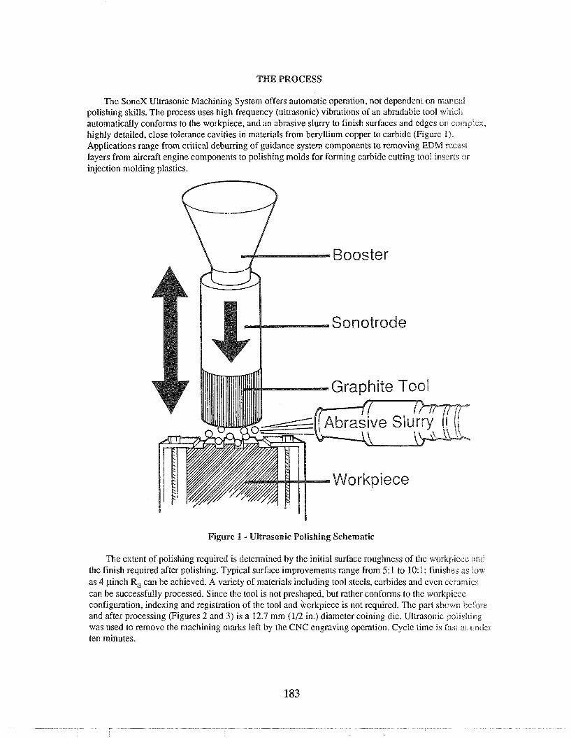
THE PROCESS
The SoneX Ultrasonic Machining System offers automatic operation, not dependent on manual polishing skills. The process uses high frequency (ultrasonic) vibrations of an abradable tool which automatically conforms to the workpiece, and an abrasive slurry to finish surfaces and edges on complex, highly detailed, close tolerance cavities in materials from beryllium copper to carbide (Figure 1). Applications range from critical deburring of guidance system components to removing EDM recast layers from aircraft engine components to polishing molds for forming carbide cutting tool inserts or injection molding plastics.
Figure 1 - Ultrasonic Polishing Schematic
The extent of polishing required is determined by the initial surface roughness of the workpiecs: aead the finish required after polishing. Typical surface improvements range from 5:l to 10:l; finishes as low as 4 pinch Ra can be achieved. A variety of materials including tool steels, carbides and even ceramics can be successfully processed. Since the tool is not preshaped, but rather conforms to the workpiece configuration, indexing and registration of the tool and workpiece is not required. The part shown before and after processing (Figures 2 and 3) is a 12.7 mm (112 in.) diameter coining die. Ultrasonic polishing was used to remove the machining marks left by the CNC engraving operation. Cycle time is fast at undcr ten minutes.

Figure 2 Figure 3 Coining die shown before and after processing.
The photomicrographs in Figures 4 and 5 compare the original ram EDM finish of 30 pinch R, on a cxkidc compacting with an area on the same die which has been ultrasonically polished to a final finish s ~ f 13 pirich Ril, removing only 0.005 mm (0.0002 in.) of material.
Figure 4 Figure 5 $hotcsmicsilgr;1phs at 3000X magnification show the surface improvement after ultrasonic polishing,
Sir~ce ihc abradable mehod described offers georneirics, including:
tool automatically conforms to the workpiece geometry, the ultrasonic finishing a number of important benefits in finishing components with complex
No specially preshaped tools are required; consequently, even low volume components are applicable;
* No precision alignment of the polishing tool to the workpiece is required;

e Work is uniform across the workpiece surface.
Surface improvement is 3:l or more on machined, EDM'd and cast surfaces;
e Edges can be deburred and lightly mdiused;
* No special operator skills are required; and
The system operates automatically without operator involvement.
To provide the background for the research performed under the PRDA project, EHC was funded under a "Seed Grant" sponsored by the Ben Franklin Program of the Commonwealth of Pennsylvania to, examine the feasibility of ultrasonic polishing. The effort yielded general ultrasonic polishing pxmeters which were examined more closely and optimized under this PRDA contract. The "Seed Grant" research was comprised of three tasks to optimize machining parameters, to examine various polishing md toon materials, and to evaluate the effects of ultrasonic polishing on various materials with different machined surfaces. From the data collected during this study i t was clear that ultrasonic polishing offers an effcciive means of improving surface finish in any material of sufficient hardness. Significant results included:
The degree of improvement is largely dependent upon the beginning surface finish; an EDM'd finish of 300 pinch (7.5 pm) R,, for example, can be ultrasonically polished to a 150 pinch (4 p m) R, in a relatively short cycle time-about 10 minutes. A 15-pinch (0.4-pm) R, ground finish, on the other hand, can probably only be improved to about a 10-pinch (0.3-pm) Ra finish with cycle times approaching 15 minutes or more.
* The best abrasives include silicon carbide for aluminum and tool steels that have not been thermally machined, boron carbide for thermally machined tool steels and soft ceramics, and diamond for tungsten carbide and hard cer'mics. Abrasive mesh sizes from 320 to 600 mesh yielded the best results with good machining speeds and acceptable surface finishes. Abrasive particle concentrations of 35 percent by volume are optimal for polishing. Vibration amplitudes range from 0.0004 in to 0.0015 in (0.01 to 0.038 mm) with the best frequencies achieved at the 20- to 20.5-kHz range.
* For most metals a static load of 4 to 8 pounds (1.8 to 3.6 kilograms) works best; while for ceramics and other brittle materials, static loads of 2 to 4 pounds (1 to 1.8 kilograms) achieve the best results. Good flushing is important to the success of the polishing process. The best carrier of abrasives is water.
Simple shapes as well as complex three-dimensional shapes can be ultrasonically polished; however, the ability to successfully polish vertical sidewalls was not clearly demonstratedl. The actual metal removal that occurs is typically less than 0.0005 in (0.013 mm).
The best horn material appears to be either nonhardened tool steel or aluminum based on cost, machinability, bonding and acoustic property considerations. A cylindrical shape offers consistent vibration amplitudes and is relatively easy to manufacture. The best bonding technique uses a two-part epoxy applied after the horn was heated.
e Graphite has proved to be the best tool material offering low cost, good availability and excellent ultrasonic abradability. A wide range of materials can be polished by ultrasonic techniques. The only limiting factor is that the material be sufficiently hard so that the abrasive particles do not impinge into the surface. The hardness of the material will affect machining speed and surfacc quality.

PROCESS CAPABILITIES
A complete report describing all of the activities associated with a PRDA program to establish and demonstrate prototype hardware and control software for automatic, close tolerance control of the finishing operation for complex components can be requested from WLJMTPM, Wright-Patterson Air Form Base, Ohio 45433-6533. The technical effort was conducted in one phase over a 24-month period. Objectives of the program were to optimize machining parameters and validate the ability of ultrasonic machining to provide reliable and reproducible finishing results. A prototype system was designed, Fabricated and assembled as part of this effort. In addition, all aspects of operation and control were tested, the process was further optimized and the entire system demonstrated. A partnership with Kennametal
Allied Signal Aerospace was established for this program. Highlights of the program are discussed.
For examining deburring and edge finishing parameters primary considerations included abrasive type (boron and silicon carbide), size (240 to 600 mesh) and concentration (20 to 40 percent). Samples were machined out of A2 tool steel with a 0.25-in (6.35-mm) slot milled across the face of the workpiece. Both srlicon and boron carbide abrasives from 320 mesh to 600 mesh were used in tests to remove the bun. Abrnsave concentration was 40 percent by volume. (In ultrasonic machining of graphite and ceramics, abrasive concentrations typically range from 12 to 25 percent.) Boron carbide performed about 50 percent faster than silicon carbide; the difference in particle size was negligible. After the full face of the vnbmtlrag tool (graphite) was in contact with the workpiece (about 10 minutes), boron carbide removed [he bum in a 5-minute cycle; silicon carbide in a 12-minute cycle. The photograph presented in Figure 6 shows two of the deburring samples, one before and one after processing.
Figure 6 - Deburring Test Samples Before and After Processing
n e r e are limitritions to the burr size which can be effectively removed with ultrasonic polishing. The minimum radius produced is dependent on the burr size as well as the abrasive grain size. With 320 mesh, a 1.002- to 0.003-in (0.05- to 0.076-mm) radius was produced. For deburring, the best results are achieved .with a flat piece of graphite rather than a preshaped tool.
Recast Removal
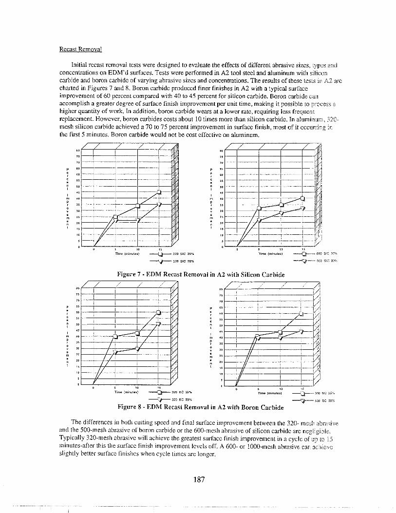
Initial recast removal tests were designed to evaluate the effects of different abrasive sizes, types and concentrations on EDM'd surfaces. Tests were performed in A2 tool steel and aluminum with silicon carbide and boron carbide of varying abrasive sizes and concentrations. The results of these tests in A2 are charted in Figures 7 and 8. Boron carbide produced finer finishes in A2 with a typical surface improvement of 60 percent compared with 40 to 45 percent for silicon carbide. Boron carbide can accomplish a greater degree of surface finish improvement per unit time, making it possible to pro, a higher quantity of work. In addition, boron carbide wears at a lower rate, requiring less frequent replacement. However, boron carbides costs about 10 times more than silicon carbide. In aluminum, 320- mesh silicon carbide achieved a 70 to 75 percent improvement in surface finish, most of it occus~ng in the first 5 minutes. Boron carbide would not be cost effective on aluminum.
0 5 10 15
Tltnc (mlnulcs) 320 SIC 35% 0 5 10 15
Tlme (rnlnules) SW SIC 35%
Figure 7 - EDM Recast Removal in A2 with Silicon Carbide
80 8 0
75 75
7 0 70
P 65 P 6* : gC 55 55
n 5 0 " 50
45 15 I
m r o m r o
P r 35 P r 35 0 Y 30
0 30
; 1 5 e m 25 ., lo .,
I 5 15
10 10
5 5
0 0
Time (mlnules) rbme (mlnules)
7 320 BC 20%
Figure 8 - EDM Recast Removal in A2 with Boron Carbide
The differences in both cutting speed and final surface improvement between the 320- mesh abrasive and the 500-mesh abrasive of boron carbide or the 600-mesh abrasive of silicon carbide are negligible. Typically 320-mesh abrasive will achieve the greatest surface finish improvement in a cycle of up to 15 minutes-after this the surface finish improvement levels off. A 600- or 1000-mesh abrasive caw 3chdelfe slightly better surface finishes when cycle times are longer.

Surface finish after EDM'ing ranged from 196 to 221pinch (5 to 5.6 pm) Ra in A2; 229 pinch (5.8 p rn) in aluminum. After polishing, finishes ranged from 88 pinch (2.2 pm) with boron carbide to 118 p inch 43 pm) with silicon carbide in A2 to 60 to 70 pinch (1.5 to 1.8 pm) in aluminum. Typical material removd iranged from 0.0001 to 0.0003 in (0.003 to 0.008 mm) for silicon carbide to 0.0003 to 0.0005 in (0.008 to 0.013 mm) for boron carbide.
A series of polishing tests was conducted on EDM'd A2 surfaces with an average incoming surface finish of approximately 100 pinch (2.5 pm). Tests were limited to polishing with boron carbide abrasives because earlier tests had shown boron carbide to be superior to silicon carbide for polishing EDM'd A2 surfaces.
With 320 mesh boron carbide, considerable work was accomplished in the initial 5 minutes of polishing. After a 5-minute cycle using a 40 percent concentration of 320 boron carbide, a 45 percent sendace finish improvement was achieved. As cycle times were increased, no noticeable surface finish improvement resulted. Further testing showed that 320 boron carbide at 55 percent concentrations did not perform as effectively; a 5-minute cycle yielded only a 28 percent improvement, 10 minutes resulted in a 40 percent improvement, and 15 minutes in a 45 percent improvement. These results are presented in Figure 9. Optimum abrasive concentration for EDM recast removal was established at 45 to 55 percent.
Recast Removal (A2) 88-108 R, Recast Removal (A2) 92-108 R,
so
75
70
P 65
: = 3 5
" 50
45
rn 40
, 3 0 Y 30
; 25 ; 20
I 3
10
3
0 0 5 I 0 15 0 5 10 13
limo (minutes) ---+ 320 BC 55% Tdme (minutes) -> 5W BC 65%
V 320 BC 40% 5W BC 45%
Figure 9 - EDM Recast Removal with Incoming Surface Finish of approximately 100 pinch (2.5 pm)
Cas these charts indicate, tests conducted with 500-mesh boron carbide showed an optimum surface improvement of 42 percent after a 15-minute polishing cycle with no appreciable difference in concenwations of 45 percent and 65 percent. With finer abrasive particles, longer cycle times do yield better surface finishes. Extended processing tests were conducted to establish whether longer cycle times would continue to show improvements in the surface finish. With beginning EDM'd finishes ranging from 104 to 112 pinch (2.6 to 2.8 pm) Ra, a 30-minute cycle yields surface finish improvements of approximately 25 percent over the initial 40 percent improvement achieved in 15 minutes. An additional 30 minutes of processing yielded only a marginal 5 percent improvement above that. While most of the surface improvement is achieved in the first 15 minutes (40 to 45 percent), additional processing of up to 15 minutes will yield a total surface improvement of 65 to 70 percent.

Residual Stress Analysis
Components that are machined with high localized energy, especially those machined by thermal processes, will commonly display stresses at the surface. These stresses are typically residual tensional stresses caused by the rapid heating and then cooling of the surface of the material being machined. In many applications, particularly for aerospace components, residual tensional stresses are not acceptable: these stresses can lead to lower cycle fatigue life because they are characterized by microcracks that when exposed to pressures or forces in use will propagate and cause cracking, which eventually could caiuse failure of the component.
A series of tests was conducted to examine the impact of ultrasonic polishing on residual stresses. Both heat treated and nonheat treated material were tested to determine what effect hardness had on residual stress. Both types of material were EDM'd prior to ultrasonic polishing. Several samples %were then ultrasonically polished and a fewer number were left unpolished to establish the degree of stress prior to ultrasonic polishing.
As a result of ultrasonic polishing, the tensional residual stresses were negated and, in fact, changed to residual compressive stresses. This type of residual stress is advantageous to the strength and fatigue cycle of the material. Normally such compressive stresses are created by shot peening, a highly uncontrollable process. With ultrasonic polishing, residual compressive stresses can be accurately and repeatedly imparted on the workpiece. Although the depth of residual compressive stress was not as great with ultrasonic polishing as with shot peening, it is believed that this can be improved with lower frequencies and/or higher power (amplitudes). A further advantage is that while the stress chxacteristics are being enhanced, the surface finish of the component is being accurately improved. Lambda Research Laboratories was contracted to analyze the results of the residual stress tests.
Examine Abilitv to Process Larger Workpieces
True ultrasonic machining occurs at a frequency of 20,000 Hz or higher when frequencies are not audible by the human ear. Ultrasonic machining and polishing at 20,000 Hz are limited to driving a tool that has a maximum surface area of 10 square inches (64.5 square cm). To operate large tools fhe frequency must be lowered out of the ultrasonic range. A 10,000-Hz generator, transducer, booster and! tool were incorporated into the prototype ultrasonic polishing system to permit processing of areas up to 25 square inches (129 square cm).
Primary concerns with 10-kHz polishing include soundproofing and tool tip attachment. A 10-kHz tool operating at 50 percent power can generate noise levels of 200 decibels-far above the OSHA guidelines. In addition to ear protection a soundproof room was constructed for the 10-kHz testing. Since wavelength at 10 kHz is twice that at 20 kHz, the cutting tool assembly is about twice as long as that of the assembly for 20 kHz (>>23.5 in compared to 13.5 in I597 mm compared to 343 mm)). This added length and larger tool make it more difficult to achieve a good bond between the tool and tip. Atbching tool tips for 20-kHz polishing is successful 80 to 90 percent of the time, while 10-kHz tool tips caw be attached properly only 30 to 40 percent of the time.
Sonic (10 kHz) polishing uses the same amplitude as ultrasonic (20 kHz) polishing, but since the surface area is considerably larger in sonic polishing, more work can be accomplished in unit lirnc. Results from the testing performed in this program show that areas up to 25 square inches (129 square cm) can be polished simultaneously. This area can be one large workpiece or a series of smaller workpieces. Testing also indicates that the resultant surface finish is comparable to that of 28-kHz polishing.
Although the feasibility of polishing larger areas at 10 kHz has been demonstrated, further testing is required to optimize polishing at this frequency. Future investigation should be aimed at the effccts of 10-

kHz sound on the human ear and how to minimize any possible hazards to the operator. Additionally, a more reliable bonding mechanism needs to be established to facilitate 10-kHz processing.
Ultrasonic Polishing Svstem
The prototype ultrasonic finishing equipment was designed in four subsystems including mechanical componealts, drive and controller systems, ultrasonic hardware and sluny system. The basic design of the supesskucteare of the machine is a four-post configuration for maintaining slide accuracies of 0.0001 in (0.003 mm). The XY worktable is capable of holding workpieces up to 18 x 24 x 12 in (457 x 610 x 305 mnl) and weighing up to 350 pounds (160 kilograms). All three axes (X, Y and Z) are driven by AC servo motors with positioning capabilities of & 0.00025 in (0.006 mm) through the full travel envelope. The Kurt Robocon I1 controller was chosen for integration due to its ability to accept analog voltage input commands from a series of force transducers built icto the tooling head; the ability to use a PC allowing customized screen generation and NC G-code programming; and the ability to control up to six axes in synchronization.
The uiltxasonic generator is capable of automatic resonance search and following allowing constant scanning of the transducer/tool assembly to continuously adjust and optimize frequency. In addition, the output power level can be adjusted from 0 to 1 kw to permit different amounts of stroke (or amplitude) to be used. Finally, the generator can be operated in both 20 and 10 kHz frequencies for processing larger workpicces.
The slurry system can deliver up to 10 gallons (38 liters) per minute to the machining area with a tubing pump incorporated for low wear and easy maintenance. The holding tank is tapered to prevent abrasive packing and a chiller is used to maintain slurry temperature.
Selected parameter data were incorporated into a menu-driven display with prepackaged programs for ahabomaiic selection of machining parameters based on the depth of the area to be polished, beginning saarfiice finish and previous machining method. Performance requirements for the workpiece, tool, machine and controller were specified.
Based on the design specifications and performance requirements, the control and machine tool were built and integrated. The control system is comprised of an IBM compatible industrial PC, monitor and keyboard; the Kurt Robocon I1 controller with a special analog input board; motion control amplifiers and scrvos; a 16-position auxiliary inputloutput board; Heidenhain linear encoders with times five multiplier boxes: a SLICE 10120 kHz, 1 kw ultrasonic generator with special interface board; operator controls and pendant workstation; and transformers for the various components. Special consideration was taken to ensure easy accessibility for trouble-shooting and maintenance.
The die set, frame assembly and weldments were subcontracted to outside vendors. The XU table was purcltslsed from Setco and incorporated special features allowing accurate mounting to the machine body. All cover and guard assemblies were fabricated at EHC and all assembly was also performed at EHC. As with thc control system, special consideration was given to accessibility and ease of maintenance. All cover asscrnblies were manufactured from Alucobond panels that can easily be removed and replaced by a siitagle individual. Assembly of the machine tool required approximately 14 weeks after receipt of all components and ran concurrently with the compIetion phase of the control system.
After completion of the control system and machine tool, integration of these subsystems as well as ihc slurqi system was begun. During integration, software control over input/output functions was verified, push button control over inputloutput functions was tested and sluny system functions were completed. Total time for the integration phase was approximately 10 to 12 weeks. The prototype system as plctured in Figure 10.

Figure 10 - Prototype Ultrasonic Polishing System
The parameters selected for testing of the completed prototype ultrasonic finishing machine isaclamded mechanical accuracy, operating software 'and operator interface, control hardware and polishiii~g performance. The XY slide was found to position within 4 0.0002 in per foot (0.005 mm per 305 mm), tracked straight within + 0.0002 in (0.005 mm) and was repeatable within k 0.0001 in (0.003 rnrn). The moveable platen positioned within + 0.0002 in (0.005 mm) of commanded position and repeated within the same tolerance. Parallelism to the worktable surface was not acceptable at the testing phase, so corrective action was implemented. The operating software was tested for the responsiveness of the servo loop interaction with load cell feedback. At the time of testing it was determined that the servo loop was not tight enough and corrective action was recommended and implemented. Control hardware wiring, particularly voltage levels and grounding, was verified. Safety issues were examined and accepted.
Testing of polishing parameters revealed that the servo loop problem impacted the stability of machining. It was decided that the corrective actions recommended for the servo loop would ~~llevintc the problem of stability. Polishing speed was examined 'and rates as high as 0.030 in (0.762 mm) of vertical travel per minute were realized. Polishing quality testing showed surface finish improvements as ~menclir as 7:1, exceeding the expected results. Parallelism of the moveable platen was determined to be us.pacceplnb&e due to poor timing between the two ballscrews. The timing was reset and parallelism was improvcd to 0.0002 in (0.005 mm) over the full platen surface. The servo loop/stability of machining problern was found to be caused by the algorithm that cor~trols this loop. A new algorithm was written to correct tt l is problem.
Process repeatability was examined based on improvement of surface finish and amount of stock removal. Stock removal ranged from 0.0001 to 0.0005 in (0.003 to 0.013 mm), dependent on i n c o m i ~ ~ g surface roughness. Stock can be removed accurately within 10 percent of the stock removed; stock can also be removed to a desired depth within 20 percent and is repeatable from workpicce to workpiece within 10 percent. Limitations observed are confined to vertical or near-vertical side walls where stock removal was as much as 50 percent less than that of frontal surfaces.
Surface finish improvements are the greatest when incoming surface roughness is high. In this case, surface finish improvements as high as 10: 1 were accomplished. On components with beginning surface finishes in the range of 100 pinch (2.5 pm) R,, improvement averaged 5 1 . Repeatability of surface finish improvement measured 2 10 percent.
Process parameters were optimized including slurry, feedJspeeds, polishing tip material, machining pressures and ultrasonic generator settings. Boron carbide is the best multi-purpose abrasive for ultrasonic polishing. With a 600-mesh abrasive, surface finishes as low as 8 to 12 pinch (0.2 to 0.3 pm) Ra are possible; finishes as low as 14 to 18 pinch (0.36 to 0.46 pm) R, can be produced using 320-mesh abrasives. Optimum abrasive concentration for most applications occurs between 18 and 22 percent by weight. Polishing tips of graphite show the most promise because they rapidly conform to the workpiece cont?guaalion and are of relatively low cost. Graphites with particles sizes of 0.00004 to 0.0001 in (0.001 to 0.003 mm) performed the best. The optimum static pressure ranges between 1 and 1.5 pounds per square inch (0.5 and 0.7 kilograms per 6.452 square centimeters).
The prototype system has been demonstrated at three international machine tool shows and has been discussed in numerous technical presentations and articles. The f i s t commercial installation has been effected for polishing ram tips used in the compacting of tungsten carbide cutting inserts. In addition a variety of contract ultrasonic finishing is being performed at EHC.
SUMMARY
Tlhe most labor intensive, uncontrollable area of production remaining in the manufacture of precision parts involves the final finish machining operations, which frequently absorb more labor time than machining. Proper finishing of edges and surfaces affects more than the appearance or feel of a product; controlled, consistent edge and surface finishing can dramatically improve product performance auld life while reducing direct labor costs. These finishing operations have been identified as the single greatest hurdle remaining in fully automating the production of precision components. By applying ultrasonic machining techniques, a process has been established for automatable, repeatable, uniform polishing with no chemical or electrical alterations in the surface. The process is applicable to a wide range of materials, including ceramics, composites, new alloys and plastics, with a level of accuracy not previously achievable. In addition, the process has the capability for integration with a tool changer for automatic loading of the workpiece and tool for uninterrupted cycling and incorporation into a flexible mmnzufacauring cell, providing consistent, uniform and repeatable results and yielding improved component performance in this final and critical phase of the complete manufacturing cycle.