
Ultrasonic machining (Usm)
12
R.K. RANA [LECTURE M.Tech (P), B.Tech, LMIEI 1 www.CrazyProf Ultraso Ultrasonic machining It is used to erode ma workpiece through th with the use of a suita The Ultrasonic Machin materials such as glas operations to provide The USM is a non-the the chemical, physica It is therefore being w materials which are n The cutting is actually in the slurry 1 (fluid). Ultrasonic machining action of the grit 3 -load workpiece. Small amplitudes and in the range of 10–20 are accelerated towar tool - through repeate section identical to its grains by shear deform Different mechanisms fracturing of the work chemical reaction due accuracy is directly de ultrasonic material re schematic of ultrason 1 Slurry: A suspension of insoluble p 2 Abrading: Rub hard or scrub 3 Grit: A hard coarse-grained siliceo ER] YouTube.com/Ram ULTRASONIC M f.in www.RamakantRana.blog onic Machining Process (USM) (USM) is a mechanical material removal proces aterial in the form of fine holes and cavities in ha he use of formed tools, vibrations of high freque able abrasive slurry-mix. ning (USM) process is suitable for machining bri ss, ceramics and semiconductors for increasingly e intricate shapes and workpiece profiles. ermal and non-chemical process which creates n al or metallurgical properties of the workpiece. widely used in the manufacturing of hard and br normally unfeasible to machine by the traditiona y performed by the abrasive particles which are accomplishes the material removal through the aded slurry which circulates between the tool an d high frequency of vibrations are given to the to 0 μm at 20–40 kHz. The hard abrasive particles in rds the workpiece surface by the oscillating acti ed abrasions, the tool further machines a cavity s own. The material removal takes place is the f mation. s could be attributed to this material process su k material, impact action of abrasives, cavitation e to the slurry. The workpiece shape and dimen ependent on the geometry of the tool. The sche emoval process is shown in following figure and nic machine in figure. particles ous sandstone makantRana MACHINING gspot.com ss. ard or brittle ency along ittle y complex no change in rittle al methods. suspended e abrading 2 nd the ool, typically n the slurry ion of the y of cross form of fine uch as brittle n and nsional ematic of the
-
Upload
ramakant-rana -
Category
Documents
-
view
254 -
download
3
description
Ultrasonic machining, also known as ultrasonic impact grinding, is a machining operation in which a vibrating tool oscillating at ultrasonic frequencies is used to remove material from the workpiece, aided by an abrasive slurry that flows freely between the workpiece and the tool.It differs from most other machining operations because very little heat is produced.The tool never contacts the workpiece and as a result the grinding pressure is rarely more than 2 pounds,which makes this operation perfect for machining extremely hard and brittle materials, such as glass, sapphire, ruby, diamond, and ceramics.
Transcript of Ultrasonic machining (Usm)

R.K. RANA [LECTURER
M.Tech (P), B.Tech, LMIEI
1 www.CrazyProf.in
Ultrasonic Machining Process (USM)
� Ultrasonic machining (USM) is a mechanical material removal process.
� It is used to erode material in the form of fine holes and cavities in hard or
workpiece through the use of formed tools, vibrations of high frequency along
with the use of a suitable abrasive slurry
� The Ultrasonic Machining (USM) process is suitable for machining brittle
materials such as glass, ceramics and semiconduct
operations to provide intricate shapes and workpiece profiles.
� The USM is a non-thermal and non
the chemical, physical or metallurgical properties of
� It is therefore being widely used in the manufacturing of hard and brittle
materials which are normally unfeasible to machine by the traditional methods.
� The cutting is actually performed by the abrasive particles which are suspended
in the slurry1 (fluid).
� Ultrasonic machining accomplishes the material removal through the
action of the grit3-loaded slurry which circulates between the tool and the
workpiece.
� Small amplitudes and high frequency of vibrations are given to the tool, typically
in the range of 10–20
are accelerated towards the workpiece surface by the oscillating action of the
tool - through repeated abrasions, the tool further machines a cavity of cross
section identical to its own. The mater
grains by shear deformation.
� Different mechanisms could be attributed to this material process such as brittle
fracturing of the work material, impact action of abrasives, cavitation and
chemical reaction due to
accuracy is directly dependent on the geometry of the tool. The schematic of
ultrasonic material removal process is shown in
schematic of ultrasonic machine in figure
1 Slurry: A suspension of insoluble particles
2 Abrading: Rub hard or scrub
3 Grit: A hard coarse-grained siliceous sandstone
LECTURER] YouTube.com/RamakantRana
ULTRASONIC MACHINING
www.CrazyProf.in www.RamakantRana.blogspot.com
Ultrasonic Machining Process (USM)
Ultrasonic machining (USM) is a mechanical material removal process.
It is used to erode material in the form of fine holes and cavities in hard or
workpiece through the use of formed tools, vibrations of high frequency along
with the use of a suitable abrasive slurry-mix.
The Ultrasonic Machining (USM) process is suitable for machining brittle
materials such as glass, ceramics and semiconductors for increasingly complex
operations to provide intricate shapes and workpiece profiles.
thermal and non-chemical process which creates no change in
the chemical, physical or metallurgical properties of the workpiece.
eing widely used in the manufacturing of hard and brittle
materials which are normally unfeasible to machine by the traditional methods.
The cutting is actually performed by the abrasive particles which are suspended
hining accomplishes the material removal through the
loaded slurry which circulates between the tool and the
Small amplitudes and high frequency of vibrations are given to the tool, typically
20 μm at 20–40 kHz. The hard abrasive particles in the slurry
are accelerated towards the workpiece surface by the oscillating action of the
through repeated abrasions, the tool further machines a cavity of cross
section identical to its own. The material removal takes place is the form of fine
grains by shear deformation.
Different mechanisms could be attributed to this material process such as brittle
fracturing of the work material, impact action of abrasives, cavitation and
chemical reaction due to the slurry. The workpiece shape and dimensional
accuracy is directly dependent on the geometry of the tool. The schematic of
ultrasonic material removal process is shown in following figure and the
ltrasonic machine in figure.
Slurry: A suspension of insoluble particles
grained siliceous sandstone
RamakantRana
MACHINING
www.RamakantRana.blogspot.com
Ultrasonic machining (USM) is a mechanical material removal process.
It is used to erode material in the form of fine holes and cavities in hard or brittle
workpiece through the use of formed tools, vibrations of high frequency along
The Ultrasonic Machining (USM) process is suitable for machining brittle
ors for increasingly complex
chemical process which creates no change in
eing widely used in the manufacturing of hard and brittle
materials which are normally unfeasible to machine by the traditional methods.
The cutting is actually performed by the abrasive particles which are suspended
hining accomplishes the material removal through the abrading2
loaded slurry which circulates between the tool and the
Small amplitudes and high frequency of vibrations are given to the tool, typically
40 kHz. The hard abrasive particles in the slurry
are accelerated towards the workpiece surface by the oscillating action of the
through repeated abrasions, the tool further machines a cavity of cross
ial removal takes place is the form of fine
Different mechanisms could be attributed to this material process such as brittle
fracturing of the work material, impact action of abrasives, cavitation and
the slurry. The workpiece shape and dimensional
accuracy is directly dependent on the geometry of the tool. The schematic of
figure and the

R.K. RANA [LECTURER
M.Tech (P), B.Tech, LMIEI
2 www.CrazyProf.in
Figure: Schematic of Ultrasonic Material Removal Process
Figure
Historical Development of US
� The historical development of Ultrasonic Machining (USM) started through the
research works in 1927.
� During investigating the
that the surface of a container which was holding the suspended abrasives
disintegrated as soon as the tip of an ultrasonically vibrating tra
placed close to it.
� Interestingly, the shape of t
tip of the transducer.
� In the early 1950’s industries started realizing its benefits and the production of
ultrasonic machines began thereafter. A wide range of brittle materials, including
glass, ceramics and diamond can be effectively machined through this process.
LECTURER] YouTube.com/RamakantRana
ULTRASONIC MACHINING
www.CrazyProf.in www.RamakantRana.blogspot.com
ematic of Ultrasonic Material Removal Process
Figure: Schematic of Ultrasonic Machine
Historical Development of USM:
The historical development of Ultrasonic Machining (USM) started through the
research works in 1927.
During investigating the ultrasonic grinding of abrasive powders, it was found
that the surface of a container which was holding the suspended abrasives
disintegrated as soon as the tip of an ultrasonically vibrating transducer was
Interestingly, the shape of the cavity, thus produced accurately reprod
In the early 1950’s industries started realizing its benefits and the production of
ultrasonic machines began thereafter. A wide range of brittle materials, including
and diamond can be effectively machined through this process.
RamakantRana
MACHINING
www.RamakantRana.blogspot.com
The historical development of Ultrasonic Machining (USM) started through the
ultrasonic grinding of abrasive powders, it was found
that the surface of a container which was holding the suspended abrasives
nsducer was
he cavity, thus produced accurately reproduced the
In the early 1950’s industries started realizing its benefits and the production of
ultrasonic machines began thereafter. A wide range of brittle materials, including
and diamond can be effectively machined through this process.

R.K. RANA [LECTURER
M.Tech (P), B.Tech, LMIEI
3 www.CrazyProf.in
Machine
The basic mechanical structure of an USM is very similar to a drill press.
However, it has additional features to carry ou
The workpiece is mounted on a
the tool using a 2 axis table.
The table can further be lowered or raised to accommodate work of different thickness.
The typical elements of an USM are (Following Figure
• Slurry delivery and return
• Feed mechanism to provide a downward feed for
machining
• The transducer, which generates the ultrasonic vibration
• The horn or concentrator, which mechanically amplifies the vibration to the
required amplitude of 15
Figure: Schematic view of an Ultrasonic Machine
The ultrasonic vibrations are produced by the transducer.
The transducer is driven by suitable signal generator followed by power amplifier.
The transducer for USM work
LECTURER] YouTube.com/RamakantRana
ULTRASONIC MACHINING
www.CrazyProf.in www.RamakantRana.blogspot.com
The basic mechanical structure of an USM is very similar to a drill press.
However, it has additional features to carry out USM of brittle work material.
The workpiece is mounted on a vice, which can be located at the desired position under
The table can further be lowered or raised to accommodate work of different thickness.
ements of an USM are (Following Figure)
urry delivery and return system
Feed mechanism to provide a downward feed force on the tool during
The transducer, which generates the ultrasonic vibration
The horn or concentrator, which mechanically amplifies the vibration to the
required amplitude of 15 – 50 μm and accommodates the tool at its tip.
Schematic view of an Ultrasonic Machine
The ultrasonic vibrations are produced by the transducer.
The transducer is driven by suitable signal generator followed by power amplifier.
The transducer for USM works on the following principle
RamakantRana
MACHINING
www.RamakantRana.blogspot.com
t USM of brittle work material.
vice, which can be located at the desired position under
The table can further be lowered or raised to accommodate work of different thickness.
ce on the tool during
The horn or concentrator, which mechanically amplifies the vibration to the
ccommodates the tool at its tip.
The transducer is driven by suitable signal generator followed by power amplifier.

R.K. RANA [LECTURER
M.Tech (P), B.Tech, LMIEI
4 www.CrazyProf.in
• Piezoelectric effect
• Magnetostrictive effect
• Electrostrictive effect
Magnetostrictive transducers are most popular an
Following figure shows a typical magnetostrictive
or concentrator is a wave-guide, which amplifies and concentrates the vibration to the
tool from the transducer.
Figure: Working of horn as mechanical amplifier of amplitude of vibration
The horn or concentrator can be of different shape like
• Tapered or conical
• Exponential
• Stepped
Machining of tapered or stepped horn is much easier as
one.
Following figure shows different horns used in USM
Fig
LECTURER] YouTube.com/RamakantRana
ULTRASONIC MACHINING
www.CrazyProf.in www.RamakantRana.blogspot.com
Piezoelectric effect
Magnetostrictive effect
Electrostrictive effect
Magnetostrictive transducers are most popular and robust amongst all.
shows a typical magnetostrictive transducer along with horn. The horn
guide, which amplifies and concentrates the vibration to the
Working of horn as mechanical amplifier of amplitude of vibration
The horn or concentrator can be of different shape like
Tapered or conical
Machining of tapered or stepped horn is much easier as compared to the exponential
shows different horns used in USM.
Figure: Different Horns used in USM
RamakantRana
MACHINING
www.RamakantRana.blogspot.com
transducer along with horn. The horn
guide, which amplifies and concentrates the vibration to the
Working of horn as mechanical amplifier of amplitude of vibration
compared to the exponential
R.K. RANA [LECTURER
M.Tech (P), B.Tech, LMIEI
5 www.CrazyProf.in
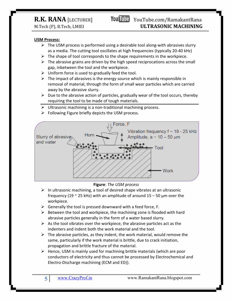
USM Process:
� The USM process is performed using a desirable tool a
as a media. The cutting tool oscillates at high frequencies (typically 20
� The shape of tool corresponds to the shape requirements
� The abrasive grains are driven by the high speed reciprocations across the small
gap, inbetween the tool and the workpiece.
� Uniform force is used to gradually feed the tool.
� The impact of abrasives is the energy source which is mainly res
removal of material, through the form of small wear particles which are carried
away by the abrasive slurry.
� Due to the abrasive action of
requiring the tool to be made of tough materials.
� Ultrasonic machining is a non
� Following Figure briefly depicts the USM process.
� In ultrasonic machining, a tool of desired shape vibrates at an ultrasonic
frequency (19 ~ 25 kHz) with an amplitude of
workpiece.
� Generally the tool is pressed
� Between the tool and workpiece, the machining zone is flooded with hard
abrasive particles generally in th
� As the tool vibrates over the workpiece, the abrasive particles act as the
indenters and indent both
� The abrasive particles, as they indent, the work material, would remove the
same, particularly if the work material is brittle, due to crack
propagation and brittle fracture of the
� Hence, USM is mainly used for machining brittle materials {which are poor
conductors of electricity and thus cannot be processed by Electrochemical and
Electro-Discharge machining (ECM and ED)}
LECTURER] YouTube.com/RamakantRana
ULTRASONIC MACHINING
www.CrazyProf.in www.RamakantRana.blogspot.com
The USM process is performed using a desirable tool along-with abrasives slurry
as a media. The cutting tool oscillates at high frequencies (typically 20
The shape of tool corresponds to the shape requirements in the workpiece.
The abrasive grains are driven by the high speed reciprocations across the small
gap, inbetween the tool and the workpiece.
Uniform force is used to gradually feed the tool.
The impact of abrasives is the energy source which is mainly responsible in
removal of material, through the form of small wear particles which are carried
away by the abrasive slurry.
Due to the abrasive action of particles, gradually wear of the tool occurs, thereby
requiring the tool to be made of tough materials.
ltrasonic machining is a non-traditional machining process.
briefly depicts the USM process.
Figure: The USM process
In ultrasonic machining, a tool of desired shape vibrates at an ultrasonic
frequency (19 ~ 25 kHz) with an amplitude of around 15 – 50 μm over the
Generally the tool is pressed downward with a feed force, F.
Between the tool and workpiece, the machining zone is flooded with hard
abrasive particles generally in the form of a water based slurry.
es over the workpiece, the abrasive particles act as the
indenters and indent both the work material and the tool.
The abrasive particles, as they indent, the work material, would remove the
same, particularly if the work material is brittle, due to crack initiation,
propagation and brittle fracture of the material.
Hence, USM is mainly used for machining brittle materials {which are poor
conductors of electricity and thus cannot be processed by Electrochemical and
ischarge machining (ECM and ED)}.
RamakantRana
MACHINING
www.RamakantRana.blogspot.com
with abrasives slurry
as a media. The cutting tool oscillates at high frequencies (typically 20-40 kHz)
in the workpiece.
The abrasive grains are driven by the high speed reciprocations across the small
ponsible in
removal of material, through the form of small wear particles which are carried
particles, gradually wear of the tool occurs, thereby
In ultrasonic machining, a tool of desired shape vibrates at an ultrasonic
50 μm over the
Between the tool and workpiece, the machining zone is flooded with hard
es over the workpiece, the abrasive particles act as the
The abrasive particles, as they indent, the work material, would remove the
initiation,
Hence, USM is mainly used for machining brittle materials {which are poor
conductors of electricity and thus cannot be processed by Electrochemical and

R.K. RANA [LECTURER
M.Tech (P), B.Tech, LMIEI
6 www.CrazyProf.in
Mechanism of Material Removal
Although the USM process is commercially used since many decades the exact details of
mechanism leading to the removal of fine materials is still
research works done till date in understanding the
light on some possible mechanisms. Through the investigations and the corresponding
literatures, the main mechanisms responsible for the material removal in USM are as
listed below:
� Mechanical abrasion:
on work piece through the tool.
� Impact: The freely moving particles impact with a certain velocity on the work
piece resulting in micro chipping.
� Erosion: Due to cavitation effect of the abrasive slurry, erosion of th
surface occurs.
� Chemical: Due to fluid employed, chemical effect can come into consideration.
It has been reported in the literature that among the above mentioned mechanisms, the
first two are primarily responsible for major stock removal. The li
erosion plays a lesser role in the removal of material for normal materials, however for
the porous materials; it is observed that erosion due to cavitations is a significant factor.
Advantages of USM
� In USM process, there are no phy
microstructures reveal that there are also no structural changes as the stresses
induced are too less. The cutting forces being low, workpiece is unstressed,
undistorted and free from heat effects.
� There is no direct contact of the tool and workpiece due to the slurry used, it
makes it a wet cutting process. The surfaces produced are free from stress and
damages.
� The process is free from burrs and distortions.
� The process is suitable for any material
� The process is very much suitable for machining brittle materials
� The process offers good surface finish and structural integrity.
Disadvantages / Limitations of USM
� Soft materials like lead and plastics are not
process, since they tend to absorb the abrasive particles rather than to chip
under their impact.
� The USM process consumes higher power and has lower material
compared to traditional fabrication processes.
� The tool wear rate in USM process is fast.
� The areas of machining and higher depths are the constraints in USM.
LECTURER] YouTube.com/RamakantRana
ULTRASONIC MACHINING
www.CrazyProf.in www.RamakantRana.blogspot.com
Mechanism of Material Removal:
Although the USM process is commercially used since many decades the exact details of
mechanism leading to the removal of fine materials is still to be understood. The
works done till date in understanding the process parameters have thrown
possible mechanisms. Through the investigations and the corresponding
mechanisms responsible for the material removal in USM are as
Mechanical abrasion: Occurs due to the hammering effect of abrasive particles
on work piece through the tool.
The freely moving particles impact with a certain velocity on the work
piece resulting in micro chipping.
Due to cavitation effect of the abrasive slurry, erosion of the work
Due to fluid employed, chemical effect can come into consideration.
It has been reported in the literature that among the above mentioned mechanisms, the
are primarily responsible for major stock removal. The literature reveals that
lesser role in the removal of material for normal materials, however for
is observed that erosion due to cavitations is a significant factor.
In USM process, there are no physical, chemical or thermal changes. The
microstructures reveal that there are also no structural changes as the stresses
induced are too less. The cutting forces being low, workpiece is unstressed,
undistorted and free from heat effects.
There is no direct contact of the tool and workpiece due to the slurry used, it
makes it a wet cutting process. The surfaces produced are free from stress and
The process is free from burrs and distortions.
The process is suitable for any materials, irrespective of electrical conductivity
The process is very much suitable for machining brittle materials
The process offers good surface finish and structural integrity.
Disadvantages / Limitations of USM
Soft materials like lead and plastics are not suitable for machining by the USM
process, since they tend to absorb the abrasive particles rather than to chip
The USM process consumes higher power and has lower material-removal rates
compared to traditional fabrication processes.
e tool wear rate in USM process is fast.
The areas of machining and higher depths are the constraints in USM.
RamakantRana
MACHINING
www.RamakantRana.blogspot.com
Although the USM process is commercially used since many decades the exact details of
to be understood. The
process parameters have thrown
possible mechanisms. Through the investigations and the corresponding
mechanisms responsible for the material removal in USM are as
hammering effect of abrasive particles
The freely moving particles impact with a certain velocity on the work
e work
Due to fluid employed, chemical effect can come into consideration.
It has been reported in the literature that among the above mentioned mechanisms, the
terature reveals that
lesser role in the removal of material for normal materials, however for
is observed that erosion due to cavitations is a significant factor.
sical, chemical or thermal changes. The
microstructures reveal that there are also no structural changes as the stresses
induced are too less. The cutting forces being low, workpiece is unstressed,
There is no direct contact of the tool and workpiece due to the slurry used, it
makes it a wet cutting process. The surfaces produced are free from stress and
s, irrespective of electrical conductivity
suitable for machining by the USM
process, since they tend to absorb the abrasive particles rather than to chip
removal rates
The areas of machining and higher depths are the constraints in USM.

R.K. RANA [LECTURER
M.Tech (P), B.Tech, LMIEI
7 www.CrazyProf.in
� As the USM process continuous, the lateral wear of the tool increases gradually
and it tends to make the holes tapered. The sharp corners of the t
rounded off thereby requiring tool replacement essential for producing accurate
blind holes.
� The accuracy of the machined surface gets lost due to setting up of strong lateral
vibrations. This occurs if the axis of the tool and horn, which are braz
are not properly aligned with the transducer axis. In such a case, the tool needs
to be redesigned.
� The holes produced in USM have a tendency to break out at the bottom owing
to the static load and high amplitudes.
� While producing deeper holes
circulation leading to presence of a fewer active grains under the tool face. Due
to this, the bottom surfaces of blind holes tend to become slightly concave.
Applications of USM
� USM process is used in mach
semiconductors, glass, ceramics, carbides etc.
� In machining of advanced ceramics for applications in auto
� In machining, wire drawing, punching or blanking of small dies
� Machining ceramic substrates
sensors used in electronic industries
� Drilling small holes in helicopter power transmission shafts and gears.
LECTURER] YouTube.com/RamakantRana
ULTRASONIC MACHINING
www.CrazyProf.in www.RamakantRana.blogspot.com
As the USM process continuous, the lateral wear of the tool increases gradually
and it tends to make the holes tapered. The sharp corners of the tool get
rounded off thereby requiring tool replacement essential for producing accurate
The accuracy of the machined surface gets lost due to setting up of strong lateral
vibrations. This occurs if the axis of the tool and horn, which are braz
are not properly aligned with the transducer axis. In such a case, the tool needs
The holes produced in USM have a tendency to break out at the bottom owing
to the static load and high amplitudes.
While producing deeper holes through USM method, there is ineffective slurry
circulation leading to presence of a fewer active grains under the tool face. Due
the bottom surfaces of blind holes tend to become slightly concave.
USM process is used in machining hard and brittle metallic alloys,
semiconductors, glass, ceramics, carbides etc.
In machining of advanced ceramics for applications in auto-engine components.
In machining, wire drawing, punching or blanking of small dies
Machining ceramic substrates for drilling holes in borosilicate glass for the
in electronic industries
Drilling small holes in helicopter power transmission shafts and gears.
RamakantRana
MACHINING
www.RamakantRana.blogspot.com
As the USM process continuous, the lateral wear of the tool increases gradually
ool get
rounded off thereby requiring tool replacement essential for producing accurate
The accuracy of the machined surface gets lost due to setting up of strong lateral
vibrations. This occurs if the axis of the tool and horn, which are brazed together,
are not properly aligned with the transducer axis. In such a case, the tool needs
The holes produced in USM have a tendency to break out at the bottom owing
through USM method, there is ineffective slurry
circulation leading to presence of a fewer active grains under the tool face. Due
the bottom surfaces of blind holes tend to become slightly concave.
engine components.
for drilling holes in borosilicate glass for the
Drilling small holes in helicopter power transmission shafts and gears.

R.K. RANA [LECTURER
M.Tech (P), B.Tech, LMIEI
8 www.CrazyProf.in
Ultrasonic Machine and its Process Parameters
The basic ultrasonic equipment consists of the
� A generator for high frequency oscillations (Ultrasonic generator)
� An acoustic head consisting of transducer and trunk (shank)
� Tool and abrasive slurry elements
The High Frequency Oscillating Current (OC) Generator
� The purpose of the OC generator is to produce high
currents.
� This generator transmits electrical power to the transducer which creates energy
impulses in the ultrasonic range i.e. 18
mechanical vibrations.
� The primary function of the transducer is to convert electrical impulses into
vertical and two dimensional
The Acoustic Head
This is the ‘heart’ of the whole equipment and consists of two parts,
A. The transducer, which converts the high
linear vibrations and
B. The trunk, which mechanically amplifies the linear vibrations.
Ultrasonic transducer
The ultrasonic vibrations are produced by a transduc
generator which gets further powered by an amplifier. The USM transducer works on
the following principle:
� Piezo-electric effect4
� Magneto-strictive effect
� Electro-strictive effect
The function of ultrasonic transducer is to converts high frequency electrical impulses
from the oscillator into mechanical vibrations. The
periodically shortens and lengthens.
For low power applications piezo
applications magneto-strictive
The trunk
It is a critical link in the ultrasonic machining system.
It is known by several names such
44 Piezo-Electric Effect: Electricity produced by mechanical pressure on certain crystals (notably quartz or
Rochelle salt); alternatively, electrostatic stress produces a change in the linear dimensions of the crystal
LECTURER] YouTube.com/RamakantRana
ULTRASONIC MACHINING
www.CrazyProf.in www.RamakantRana.blogspot.com
Ultrasonic Machine and its Process Parameters
The basic ultrasonic equipment consists of the following elements:
A generator for high frequency oscillations (Ultrasonic generator)
An acoustic head consisting of transducer and trunk (shank)
Tool and abrasive slurry elements
The High Frequency Oscillating Current (OC) Generator:
The purpose of the OC generator is to produce high frequency oscillating
generator transmits electrical power to the transducer which creates energy
the ultrasonic range i.e. 18-20 KHz and converts them into
vibrations.
primary function of the transducer is to convert electrical impulses into
dimensional strokes.
This is the ‘heart’ of the whole equipment and consists of two parts,
The transducer, which converts the high frequency output of the generator
The trunk, which mechanically amplifies the linear vibrations.
The ultrasonic vibrations are produced by a transducer that is driven by the signal
ther powered by an amplifier. The USM transducer works on
strictive effect
strictive effect
The function of ultrasonic transducer is to converts high frequency electrical impulses
from the oscillator into mechanical vibrations. The periodicity of these vibrations
periodically shortens and lengthens.
piezo-electric transducers are used, whereas for
strictive transducers are commonly used.
he ultrasonic machining system.
is known by several names such as shank, horn, concentrator and amplifier.
Electricity produced by mechanical pressure on certain crystals (notably quartz or
alternatively, electrostatic stress produces a change in the linear dimensions of the crystal
RamakantRana
MACHINING
www.RamakantRana.blogspot.com
Ultrasonic Machine and its Process Parameters
frequency oscillating
generator transmits electrical power to the transducer which creates energy
hem into
primary function of the transducer is to convert electrical impulses into
frequency output of the generator into
er that is driven by the signal
ther powered by an amplifier. The USM transducer works on
The function of ultrasonic transducer is to converts high frequency electrical impulses
periodicity of these vibrations
are used, whereas for high power
as shank, horn, concentrator and amplifier.
Electricity produced by mechanical pressure on certain crystals (notably quartz or
alternatively, electrostatic stress produces a change in the linear dimensions of the crystal.

R.K. RANA [LECTURER
M.Tech (P), B.Tech, LMIEI
9 www.CrazyProf.in
The trunk amplifies and focuses vibrations of
necessary enough for driving the
The increase in amplitude of vibrations at the tool end is
section of the trunk.
The Tool
The tool is designed to provide the maximum amplitude
selection of tool material is very important as the tool tip i
must not fail due to wear.
The commonly used tool materials are brass, high speed
stainless steel, tungsten carbide and monel
silver brazing or by hard soldering. At times it is fastened (screwed) with
The Abrasive Slurry
The recommended slurry to be used in this process is a mi
liquid (water or kerosene). The slurry is pumped across the tool
part of the machine-system. The properties requir
abrasives include low viscosity, good wetting and high t
recommended medium for abrasive transportation which generally m
process requirement.
Process Parameters in USM
The determination of accurate process parameters which a
ultrasonic machining is hard to determine as i
The geometry and material properties of the work piece and tool make the system
further complex to ascertain its performance characteristics.
However, the performance of ultrasonic
machining rate, machining accuracy, surface
parameters which can affect the performance of USM
four major groups. In order to identify the process
qualities of the machined surface, an Ishikawa cause
is constructed.
5 Monel: An alloy of nickel and copper and other metals (such as iron and/or manganese and/or
aluminium).
LECTURER] YouTube.com/RamakantRana
ULTRASONIC MACHINING
www.CrazyProf.in www.RamakantRana.blogspot.com
ifies and focuses vibrations of the transducer to the required intensity
necessary enough for driving the tool.
increase in amplitude of vibrations at the tool end is obtained by reducing the cross
The tool is designed to provide the maximum amplitude of vibration at the free end. The
selection of tool material is very important as the tool tip is subjected to vibration and it
materials are brass, high speed steel, mild-steel, silver,
tungsten carbide and monel5. The tool is attached to the trunk (horn) by
silver brazing or by hard soldering. At times it is fastened (screwed) with the trunk.
The recommended slurry to be used in this process is a mixture of abrasive particles and
liquid (water or kerosene). The slurry is pumped across the tool face. Slurry pump is a
system. The properties required from the transport medium of
abrasives include low viscosity, good wetting and high thermal conductivity. Water is a
recommended medium for abrasive transportation which generally meets most of the
The determination of accurate process parameters which affect performance of
ng is hard to determine as it works under multiple factors.
material properties of the work piece and tool make the system
ascertain its performance characteristics.
However, the performance of ultrasonic machining, to some extent is decided by the
machining rate, machining accuracy, surface finish and tool wear. The process
parameters which can affect the performance of USM are arranged into the following
four major groups. In order to identify the process parameters in USM affecting the
qualities of the machined surface, an Ishikawa cause – effect diagram as shown in Fig
: An alloy of nickel and copper and other metals (such as iron and/or manganese and/or
RamakantRana
MACHINING
www.RamakantRana.blogspot.com
the transducer to the required intensity
obtained by reducing the cross
of vibration at the free end. The
s subjected to vibration and it
steel, silver,
trunk (horn) by
the trunk.
particles and
face. Slurry pump is a
ed from the transport medium of
hermal conductivity. Water is a
eets most of the
ffect performance of
t works under multiple factors.
material properties of the work piece and tool make the system
some extent is decided by the
finish and tool wear. The process
are arranged into the following
USM affecting the
ffect diagram as shown in Fig.1
: An alloy of nickel and copper and other metals (such as iron and/or manganese and/or

R.K. RANA [LECTURER
M.Tech (P), B.Tech, LMIEI
10 www.CrazyProf.in
Figure 1: Ishikawa Cause and effect diagram showing Performance in USM
The process parameters which govern the ultrasonic
identified and the same are listed below
• Amplitude of vibration (a
• Frequency of vibration (f)
• Feed force (F) – related to tool dimensions
• Feed pressure (p)
• Abrasive size –
• Abrasive material
• Flow strength of work material
• Flow strength of the tool material
• Contact area of the tool
• Volume concentration of abrasive in water slurry
LECTURER] YouTube.com/RamakantRana
ULTRASONIC MACHINING
www.CrazyProf.in www.RamakantRana.blogspot.com
kawa Cause and effect diagram showing Performance in USM
The process parameters which govern the ultrasonic machining process have been
identified and the same are listed below along with material parameters:
• Amplitude of vibration (ao) – 15 – 50 μm
• Frequency of vibration (f) – 19 – 25 kHz
related to tool dimensions
15 μm – 150 μm
- Al2O3
- SiC
- B4C
- Boronsilicarbide
- Diamond
• Flow strength of work material
• Flow strength of the tool material
• Contact area of the tool – A
• Volume concentration of abrasive in water slurry – C
RamakantRana
MACHINING
www.RamakantRana.blogspot.com
machining process have been
R.K. RANA [LECTURER
M.Tech (P), B.Tech, LMIEI
11 www.CrazyProf.in
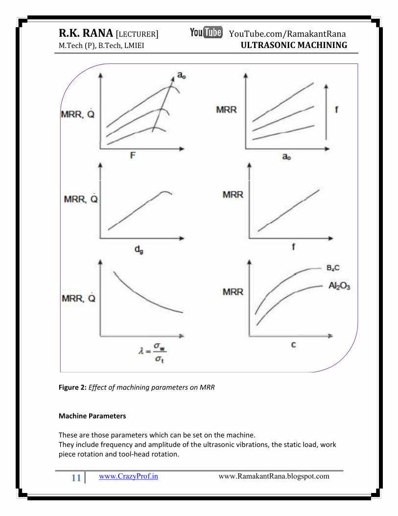
Figure 2: Effect of machining parameters on MRR
Machine Parameters
These are those parameters w
They include frequency and amplitude of the ultrasonic vibrations,
piece rotation and tool-head
LECTURER] YouTube.com/RamakantRana
ULTRASONIC MACHINING
www.CrazyProf.in www.RamakantRana.blogspot.com
Effect of machining parameters on MRR
These are those parameters which can be set on the machine.
amplitude of the ultrasonic vibrations, the static load, work
rotation.
RamakantRana
MACHINING
www.RamakantRana.blogspot.com
the static load, work

R.K. RANA [LECTURER
M.Tech (P), B.Tech, LMIEI
12 www.CrazyProf.in
Abrasive Slurry Characteristics
The type and size of the abrasives particles, its hardne
carrier to form the abrasive slurry and the concentration of abrasive pa
slurry.
Work piece properties
The hardness, fracture characteristics, strength, work
properties of the work material also affect the process performance.
Tool Material Properties and Tool Geometry
The shape of the tool (solid or hollow), mechanical properties of the ma
tool-making are some of the other parameters
performance.
Rotary Ultrasonic Machining (RUM)
If the ultrasonic machining equipment possesses
ultrasonic head or at the worktable for drilling, milling, an
is termed as Rotary Ultrasonic Machine (RUM). In
combination of rotational motion and axial vibrations (of
the tool and the work piece material, provides uniform tool wear, a high degree of hole
roundness and rapid removal of material from the cutting zone.
LECTURER] YouTube.com/RamakantRana
ULTRASONIC MACHINING
www.CrazyProf.in www.RamakantRana.blogspot.com
Abrasive Slurry Characteristics
The type and size of the abrasives particles, its hardness, type of the fluid used as a
carrier to form the abrasive slurry and the concentration of abrasive particles in the
The hardness, fracture characteristics, strength, work hardening tendency and fatigue
properties of the work material also affect the process performance.
Tool Material Properties and Tool Geometry
of the tool (solid or hollow), mechanical properties of the material used in
making are some of the other parameters that may affect the USM process
Rotary Ultrasonic Machining (RUM)
If the ultrasonic machining equipment possesses a rotary movement either at the
ultrasonic head or at the worktable for drilling, milling, and threading operations, then it
is termed as Rotary Ultrasonic Machine (RUM). In rotary ultrasonic machines the
combination of rotational motion and axial vibrations (of tool) reduce friction betwee
tool and the work piece material, provides uniform tool wear, a high degree of hole
and rapid removal of material from the cutting zone.
RamakantRana
MACHINING
www.RamakantRana.blogspot.com
ss, type of the fluid used as a
rticles in the
hardening tendency and fatigue
terial used in
that may affect the USM process
ry movement either at the
d threading operations, then it
rotary ultrasonic machines the
tool) reduce friction between
tool and the work piece material, provides uniform tool wear, a high degree of hole


![Expert System Approach for Optimization of Design and ...admt.iaumajlesi.ac.ir/article_538309_377e1fc... · ultrasonic machining (USM) [18]. Unlike USM, instead of using the loose](https://static.fdocuments.us/doc/165x107/607048d085b78d74276a6a05/expert-system-approach-for-optimization-of-design-and-admt-ultrasonic-machining.jpg)


