Ultra Wide Band Signal Simulations Using FDTD Method · Kai Siwiak: 15 September 2001 3 UWB...
26
Kai Siwiak: 15 September 2001 1 Ultra Wide Band Signal Simulations Using FDTD Method Kazimierz “Kai” Siwiak Time Domain Corporation Tadeusz M. Babij Florida International University 27-28 September 2001 The Boston Marriott Hotel Newton, Massachusetts
Transcript of Ultra Wide Band Signal Simulations Using FDTD Method · Kai Siwiak: 15 September 2001 3 UWB...
Kai Siwiak: 15 September 20011
Ultra Wide Band Signal Simulations Using FDTD Method
Kazimierz “Kai” SiwiakTime Domain Corporation
Tadeusz M. BabijFlorida International University
27-28 September 2001
The Boston Marriott Hotel Newton, Massachusetts
Kai Siwiak: 15 September 20012
Introduction
4 UWB signals generally more complex than sinusoids [1, 2]4 Sinusoids remains sinusoidal throughout link4 UWB waveforms and spectra change from transmitter,
to radiation, to the receiver
4 FDTD method used to study waveforms across link4 Compared with measurements4 Receiver efficiency predicted
4 UWB Wireless link characterized
Kai Siwiak: 15 September 20013
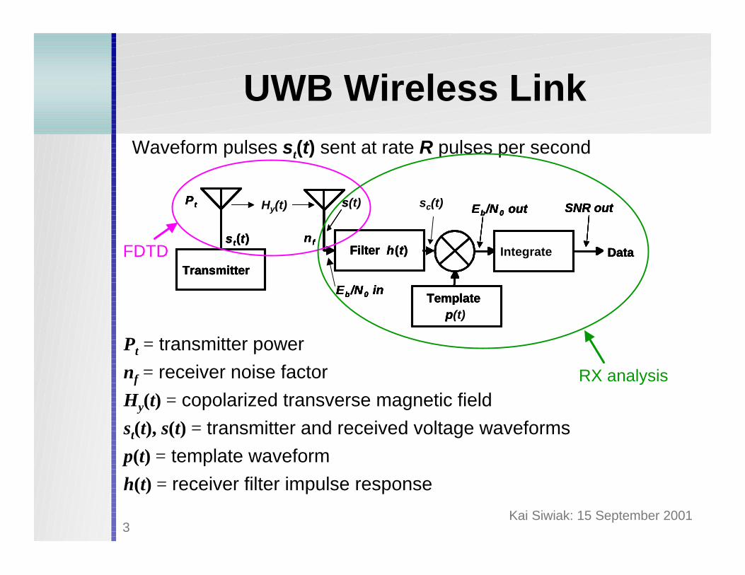
UWB Wireless LinkWaveform pulses st(t) sent at rate R pulses per second
Pt = transmitter powernf = receiver noise factorHy(t) = copolarized transverse magnetic fieldst(t), s(t) = transmitter and received voltage waveformsp(t) = template waveformh(t) = receiver filter impulse response
Template p
DataTransmitter
Eb /N0 in
Eb/N 0 out
n f
SNR out
Filter h(t)
P t
s t(t)
Template p
DataTransmitter
Eb /N0 in
Eb/N 0 out
n f
SNR out
Filter h(t)
P t
s t(t)
s
Integrate
Template p
DataTransmitter
Eb /N0 in
Eb/N 0 out
n f
SNR out
Filter h(t)
P t
s t(t)
Template p(t)
DataTransmitter
Eb /N0 in
Eb/N 0 out
n f
Hy(t) SNR out
Filter h(t)
P t
s t(t)
s(t) sc(t)
FDTD
RX analysis
Kai Siwiak: 15 September 20014
FDTD Simulations
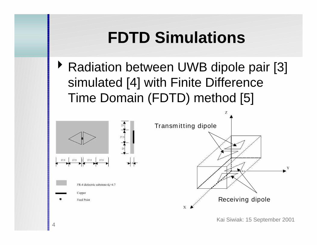
4Radiation between UWB dipole pair [3] simulated [4] with Finite Difference Time Domain (FDTD) method [5]
Transmitting dipole
Receiving dipole
Kai Siwiak: 15 September 20015
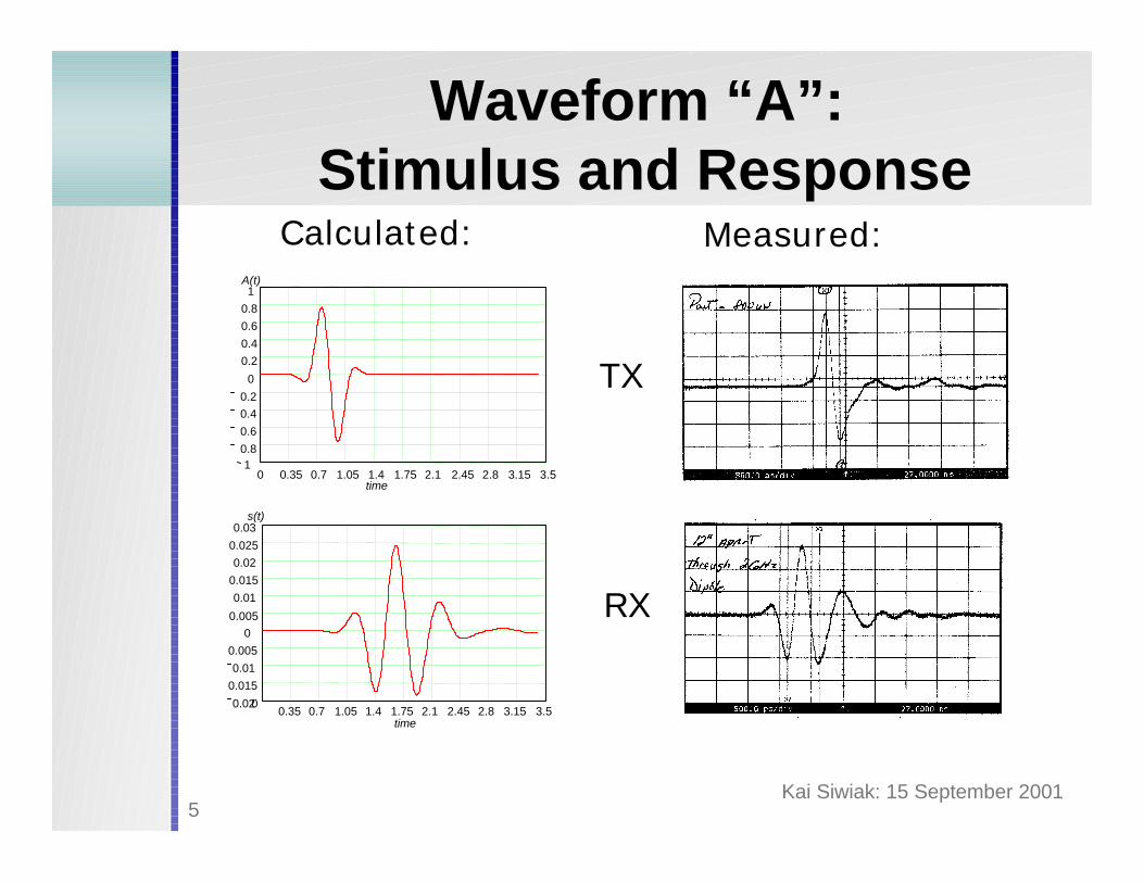
Waveform “A”:Stimulus and Response
0 0.35 0.7 1.05 1.4 1.75 2.1 2.45 2.8 3.15 3.51
0.80.60.40.2
0
0.20.40.60.81
time
A(t)
Calculated: Measured:
00.35 0.7 1.05 1.4 1.75 2.1 2.45 2.8 3.15 3.5
0.02
0.0150.01
0.0050
0.005
0.010.0150.02
0.025
0.03
time
s(t)
TX
RX

Kai Siwiak: 15 September 20016
XFDTD Simulations of UWB Waveforms and their Spectra
In time:
In frequency:
“A” at TX antenna: H-field: RX antenna load:
0 2 4 6 8 10 12 14-100
-75
-50
-25
0
Frequency(GHz)
dB
0 2 4 6 8 10 12 14Frequency(GHz)
-100
-75
-50
-25
0dB
Frequency(GHz)0 2 4 6 8 10 12 14
-100
-75
-50
-25
0dB
Kai Siwiak: 15 September 20017
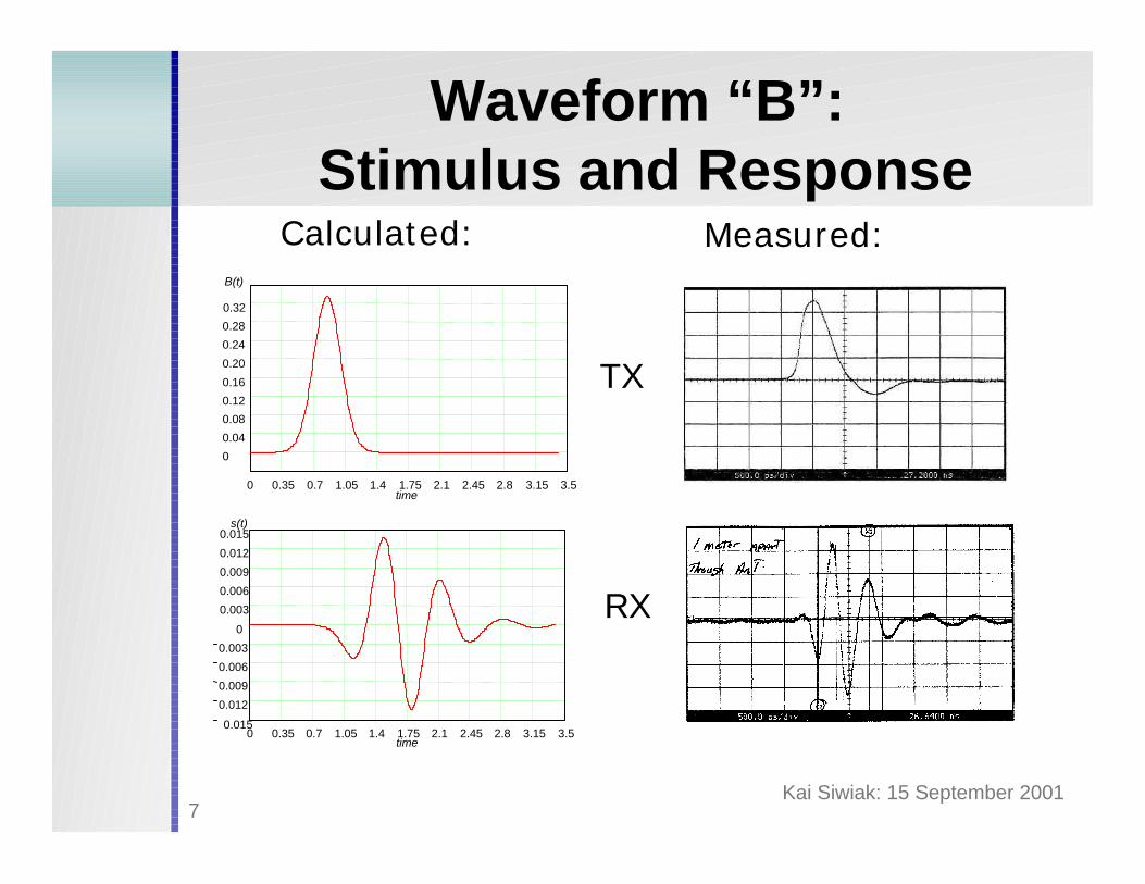
Waveform “B”:Stimulus and Response
Calculated: Measured:
0 0.35 0.7 1.05 1.4 1.75 2.1 2.45 2.8 3.15 3.5
0
0.04
0.08
0.12
0.20
0.24
0.28
0.32
0.16
B(t)
time
0 0.35 0.7 1.05 1.4 1.75 2.1 2.45 2.8 3.15 3.50.015
0.012
0.009
0.006
0.003
0
0.003
0.006
0.009
0.012
0.015s(t)
time
TX
RX
Kai Siwiak: 15 September 20018
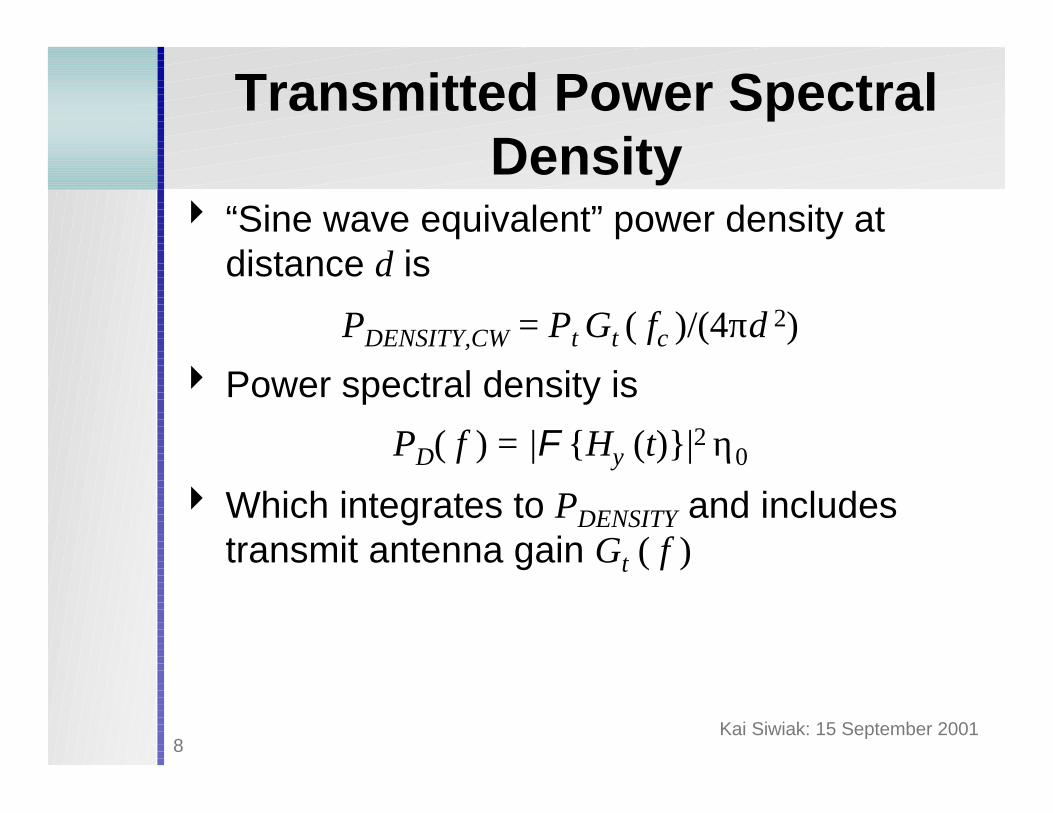
Transmitted Power Spectral Density
4 “Sine wave equivalent” power density at distance d is
PDENSITY,CW = Pt Gt ( fc )/(4πd 2)
4 Power spectral density is
PD( f ) = |F {Hy (t)}|2 η0
4 Which integrates to PDENSITY and includes transmit antenna gain Gt ( f )
Kai Siwiak: 15 September 20019
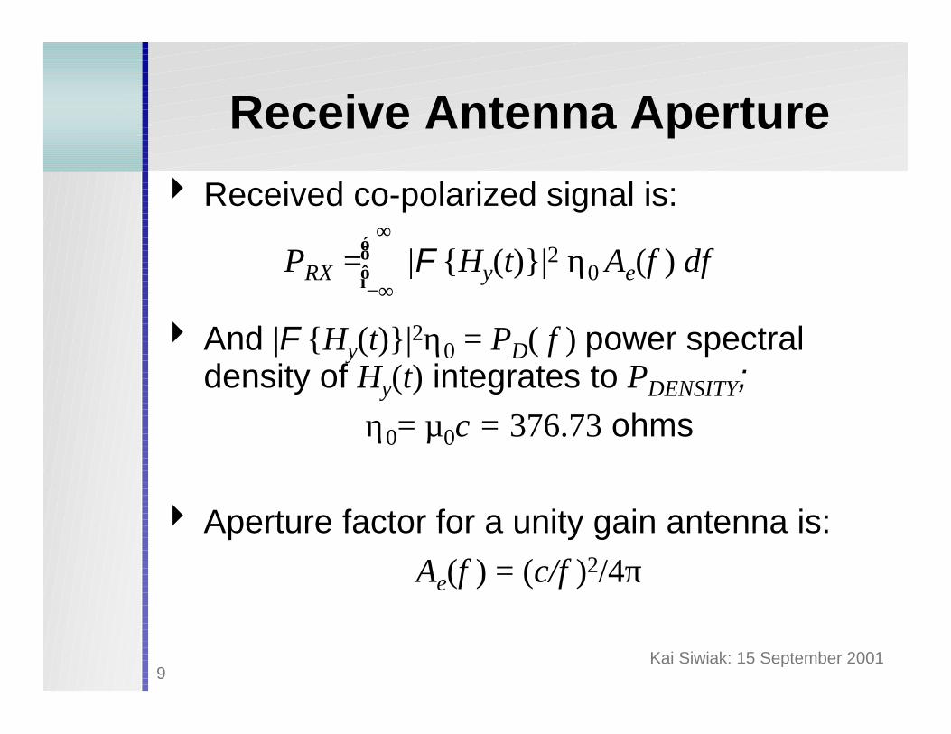
Receive Antenna Aperture
4 Received co-polarized signal is:
4 And |F {Hy(t)}|2η0 = PD( f ) power spectral density of Hy(t) integrates to PDENSITY;
η0= µ0c = 376.73 ohms
4 Aperture factor for a unity gain antenna is:Ae(f ) = (c/f )2/4π
PRX = |F {Hy(t)}|2 η0 Ae(f ) df⌠⌡
∞
−∞
Kai Siwiak: 15 September 200110
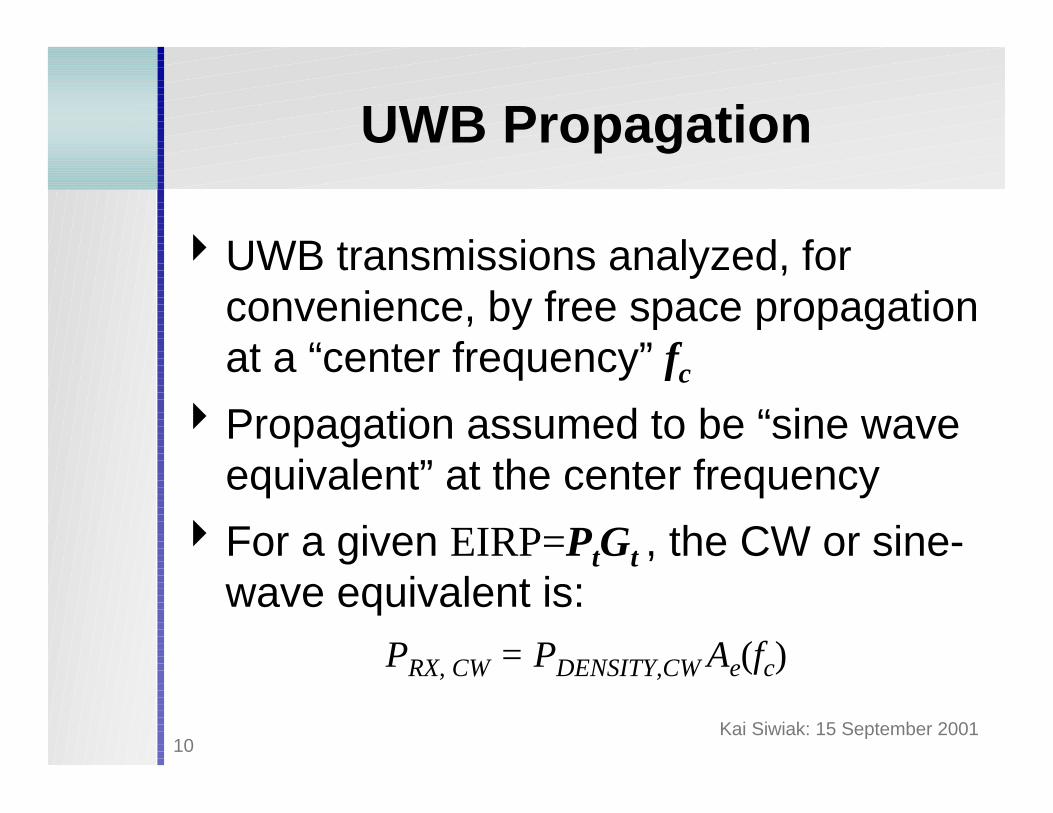
UWB Propagation
4UWB transmissions analyzed, for convenience, by free space propagation at a “center frequency” fc
4Propagation assumed to be “sine wave equivalent” at the center frequency
4For a given EIRP=PtGt , the CW or sine-wave equivalent is:
PRX, CW = PDENSITY,CW Ae(fc)
Kai Siwiak: 15 September 200111
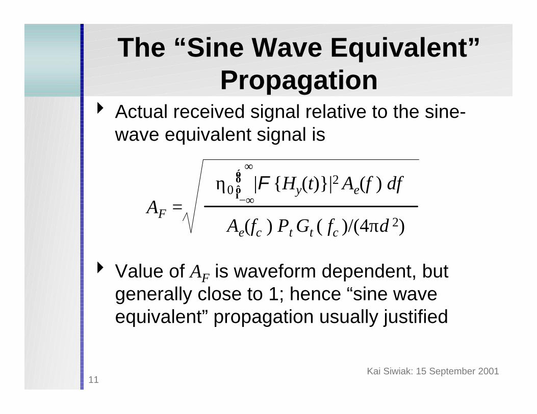
The “Sine Wave Equivalent” Propagation
4 Actual received signal relative to the sine-wave equivalent signal is
4 Value of AF is waveform dependent, but generally close to 1; hence “sine wave equivalent” propagation usually justified
η0 |F {Hy(t)}|2 Ae(f ) df⌠⌡
∞
−∞
Ae(fc ) Pt Gt ( fc )/(4πd 2)AF =
Kai Siwiak: 15 September 200112
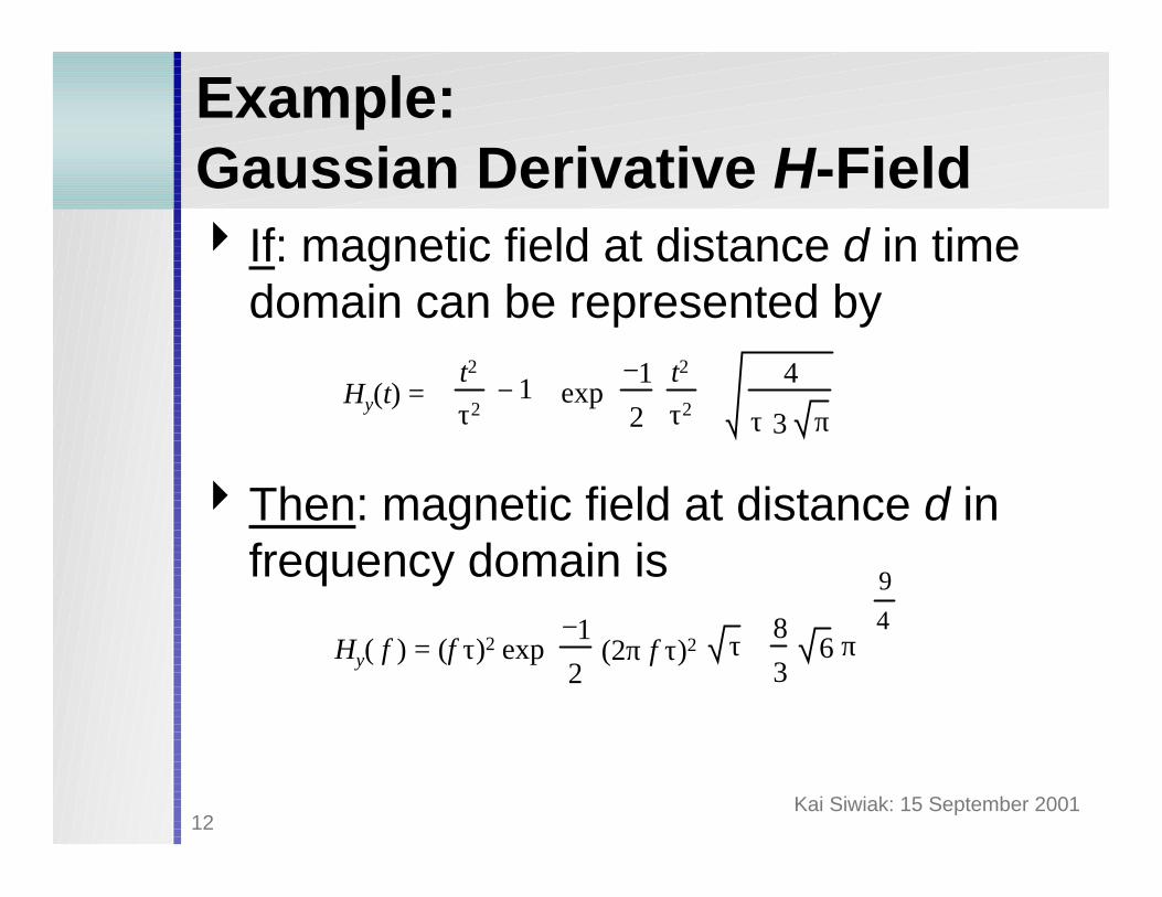
Example:Gaussian Derivative H-Field4 If: magnetic field at distance d in time
domain can be represented by
4Then: magnetic field at distance d in frequency domain is
Hy(t) = t2
τ21−
exp1−
2
t2
τ2
4
τ 3 π
exp1−
2(2π f τ)2
τ 83
6 π
94
Hy( f ) = (f τ)2
Kai Siwiak: 15 September 200113
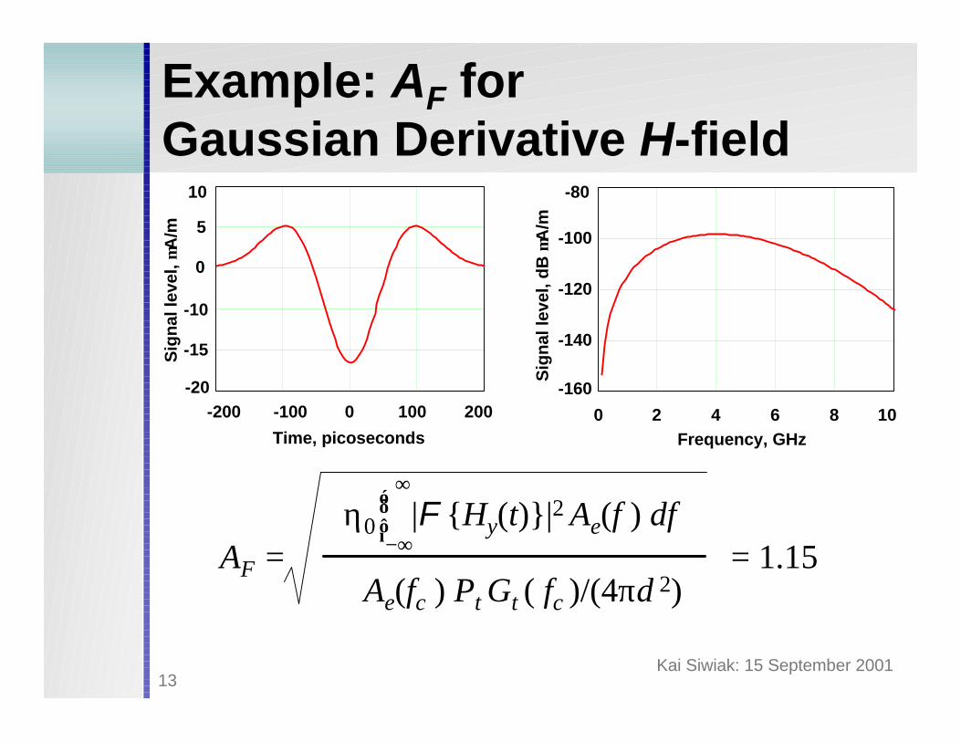
Example: AF for Gaussian Derivative H-field
-200 -100 0 100 200
-15
-10
0
5
10
-20
Time, picoseconds
Sig
nal
leve
l, µA
/m
0 2 4 6 8 10
-160
-140
-120
-100
-80
Frequency, GHz
Sig
nal
leve
l, d
B µ
A/m
= 1.15η0 |F {Hy(t)}|2 Ae(f ) df
⌠⌡
∞
−∞
Ae(fc ) Pt Gt ( fc )/(4πd 2)AF =
Kai Siwiak: 15 September 200114
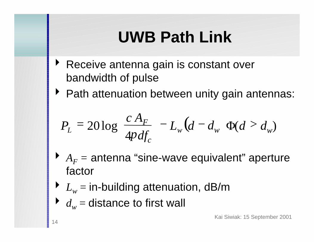
UWB Path Link
4 Receive antenna gain is constant over bandwidth of pulse
4 Path attenuation between unity gain antennas:
4 AF = antenna “sine-wave equivalent” aperture factor
4 Lw = in-building attenuation, dB/m4 dw = distance to first wall
( ) dw)(dw4log20 >−−
= ddL
dfc
c AFP wL Φπ
Kai Siwiak: 15 September 200115
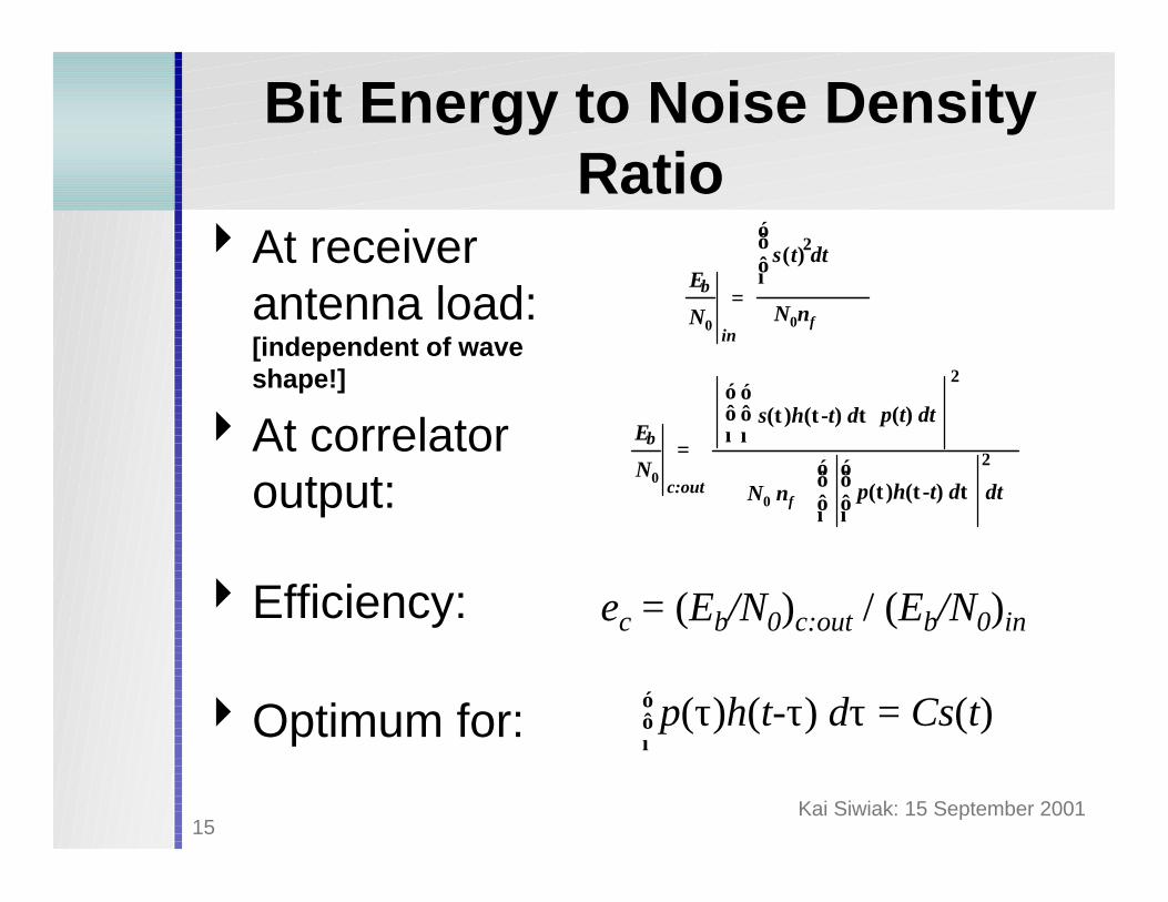
Bit Energy to Noise Density Ratio
4At receiver antenna load: [independent of wave shape!]
4At correlator output:
4Efficiency:
4Optimum for:
Eb
s t( )2⌠⌡
dt
=N0nf
inN0
p(t) dt
2
Eb =
c:out⌠⌡
N0N0 nf
s(τ)h(τ-t) dτ⌠⌡
⌠⌡
p(τ)h(τ-t) dτ⌠⌡
2
dt
ec = (Eb/N0)c:out / (Eb/N0)in
p(τ)h(t-τ) dτ = Cs(t)⌠⌡
Kai Siwiak: 15 September 200116
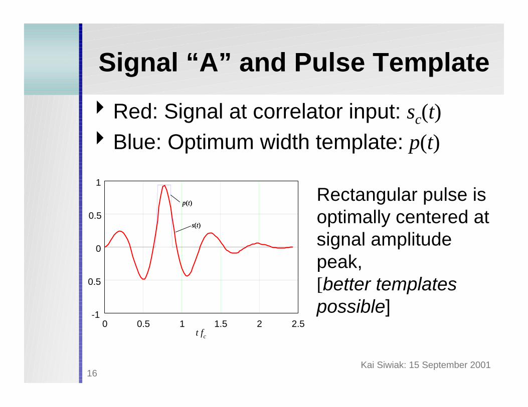
Signal “A” and Pulse Template
4Red: Signal at correlator input: sc(t)4Blue: Optimum width template: p(t)
Rectangular pulse is optimally centered at signal amplitude peak,[better templates possible]
t fc
0 0.5 1 1.5 2 2.5-1
0.5
0
0.5
1
p(t)p(t)
s(t)s(t)

Kai Siwiak: 15 September 200117
Sampler Cell Efficiency “A” Waveform
4Efficiency ec vs. template width tfc with rectangular template pulse p(t)
0 1 2 3 40
0.1
0.2
0.3
0.4
0.5
0.6
t fc
ec
Efficiency: -2.8 dB
Kai Siwiak: 15 September 200118
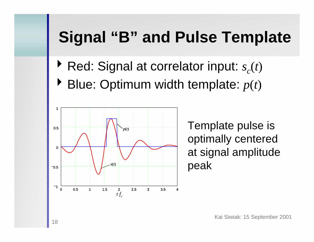
Signal “B” and Pulse Template
4Red: Signal at correlator input: sc(t)4Blue: Optimum width template: p(t)
Template pulse is optimally centered at signal amplitude peak
0 0.5 1 1.5 2 2.5 3 3.5 41
0.5
0
0.5
1
s(t)
p(t)
0 0.5 1 1.5 2 2.5 3 3.5 41
0.5
0
0.5
1
s(t)
p(t)
t fc
Kai Siwiak: 15 September 200119
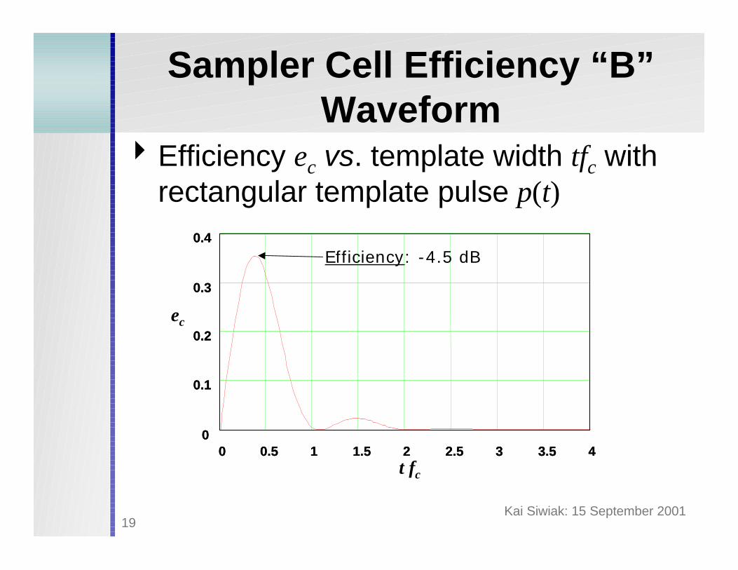
Sampler Cell Efficiency “B” Waveform
t fc
0 0.5 1 1.5 2 2.5 3 3.5 40
0.1
0.2
0.3
0.4
0 0.5 1 1.5 2 2.5 3 3.5 40
0.1
0.2
0.3
0.4
ec
Efficiency: -4.5 dB
4Efficiency ec vs. template width tfc with rectangular template pulse p(t)
Kai Siwiak: 15 September 200120
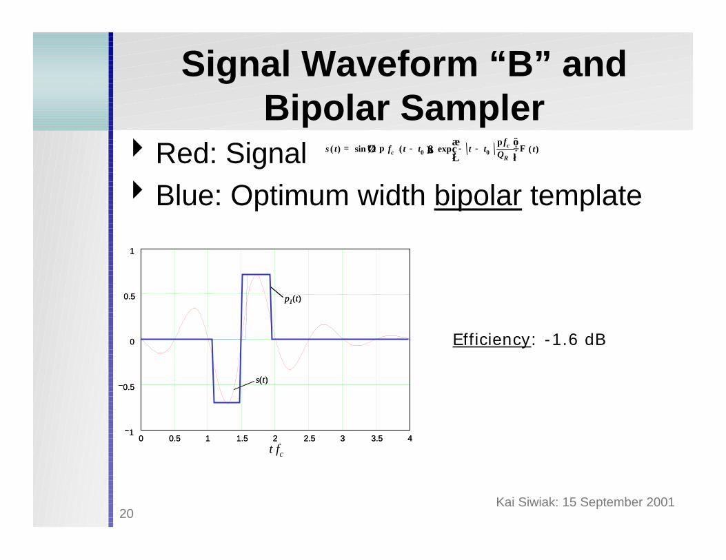
Signal Waveform “B” and Bipolar Sampler
4Red: Signal4Blue: Optimum width bipolar template
s t( ) sin 2 π fc t t0−( ) exp t t0−−π fc
QR
Φ t( )=
0 0.5 1 1.5 2 2.5 3 3.5 41
0.5
0
0.5
1
s(t)
p1(t)
0 0.5 1 1.5 2 2.5 3 3.5 41
0.5
0
0.5
1
s(t)
p1(t)
t fc
Efficiency: -1.6 dB

Kai Siwiak: 15 September 200121
Receiver System SNR
4Received power [6] is:
PRX= PEIRP (Af c/4πdfc)2 10-Lw(d-dw)Φ(d >dw)
4 Input signal to noise at impulse rate R:
SNRin= (Eb /N0)in R/BRF = PRX / nf kTBRF
4Receiver implementation losses:Lsys= -10 log(ec /nf)
Kai Siwiak: 15 September 200122
Receiver System SNR
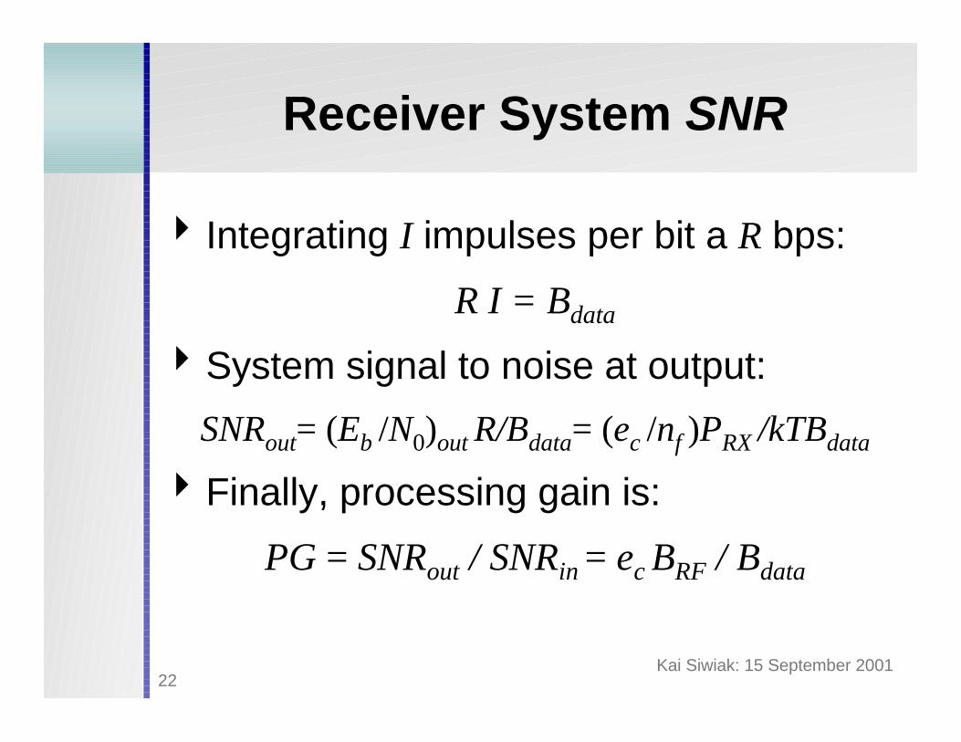
4 Integrating I impulses per bit a R bps:
R I = Bdata
4System signal to noise at output:
SNRout= (Eb /N0)out R/Bdata= (ec /nf )PRX /kTBdata
4Finally, processing gain is:
PG = SNRout / SNRin = ec BRF / Bdata
Kai Siwiak: 15 September 200123
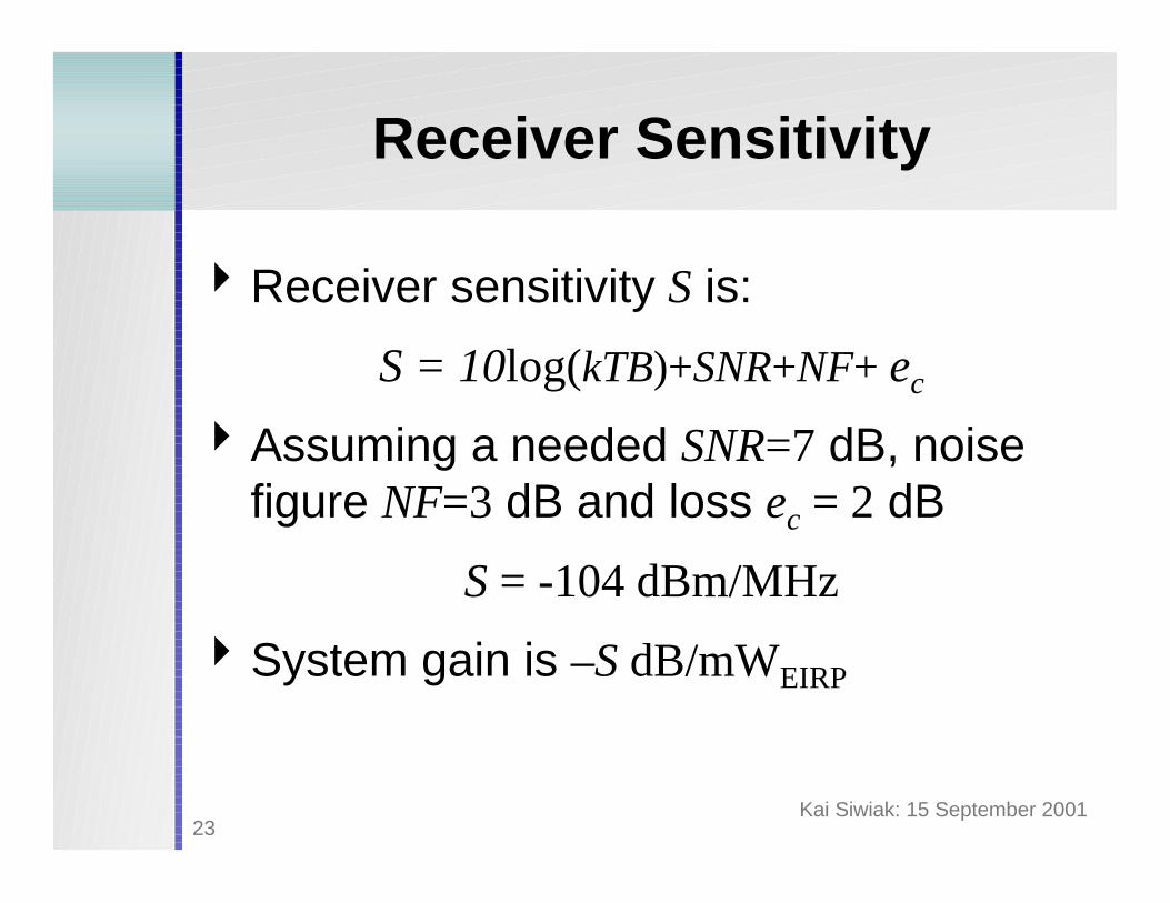
Receiver Sensitivity
4Receiver sensitivity S is:
S = 10log(kTB)+SNR+NF+ ec
4Assuming a needed SNR=7 dB, noise figure NF=3 dB and loss ec = 2 dB
S = -104 dBm/MHz
4System gain is –S dB/mWEIRP
Kai Siwiak: 15 September 200124
Summary
4 Impulse transmissions studied using FDTD method
4 Link performance impacted by UWB wave forms
4 UWB Receiver performance characterized4 Watch future IEEE VTS News for:
UWB Radio: an Emerging PAN and Positioning Technology
Kai Siwiak: 15 September 200125
References1. K. Siwiak, “Ultra-Wide Band Radio: Introducing a New Technology,”
Invited Plenary Paper, Conference Proceedings of the IEEE VTC-2001, Rhodes, Greece, May 6-9, May 2001.
2. Robert A. Scholtz, Moe Z. Win, “Impulse Radio”, Invited Paper, IEEE PIMRC'97, 1997, pp. 245-267.
3. Hans Gregory Schantz, Larry Fullerton, “The Diamond Dipole: A Gaussian Impulse Antenna”, IEEE APS Conf., Boston MA., July 2001.
4. Zhong Yang, “Finite Difference Time Domain Analysis of Antennas Used in Personal Communications,” Florida International University, M.S.E.E. Thesis Defense, 22 June 2001.
5. K. Kunz and R. J. Luebbers, The Finite Difference Time Domain Method for Electromagnetics, CRC Press Inc., 1993.
6. K. Siwiak, A. Petroff, “A Path Link Model for UWB Pulse Transmissions,” Conference Proceedings of the IEEE VTC-2001, Rhodes, Greece, May 6-9, May 2001.

Kai Siwiak: 15 September 200126
Kai Siwiak, Vice President – Strategic [email protected]+1(954)-755-6828 +1(256)-990-9062Time Domain Corporation7057 Old Madison PikeHuntsville, AL 35806
Tadeusz M. Babij, Professor Department of Electrical and Computer Engineering
[email protected]+1(305)-348-2683Florida International UniversityUniversity Park Campus, Miami, Florida 33199