ULTRA SERIES CIRCULATING AIR SOURSE HEAT … · Note. 7 Heat Pump Water Heater Technical Sales...
16
TER CONDITIONERS GREE MAKING BETTER CONDITIONERS GREE MAKING BETTER CONDITIONERS GREE MAKING BETTER CONDIT TTER CONDITIONERS GREE MAKING BETTER CONDITIONERS GREE MAKING BETTER CONDITIONERS GREE MAKING BETTER CONDI TECHNICAL SALES GUIDE-50Hz CAPACITY RANGE:28~53kW OPERATION RANGE :AMBIENT OPERATION -26 ~46 (GC201503- ) GREE ELECTRIC APPLIANCES INC.OF ZHUHAI ULTRA SERIES CIRCULATING AIR SOURSE HEAT PUMP WATER HEATER G G GR R R R R R R R R R R R G GR GR GR R R R R R G GR R G G E E EE EE EE E E E M M MA A A A AK AK A A A A A IN ING G BE B BE B BE B B BE E E E E E E E E BE BE E E E BE E E E E E E BE E E E E E E E E E E E E E E E E E E E E E E E E E E E E E E E E E E E ETT T T T TT T T T T T T T TT TT T T T T T T T T T TT T T T T T T T T TT T T T T T T T T T T T T T T TT T T T T TT T T T T T TT TT T T T T TT TT T T T T T T T T T T TT T T T T TT T T T T T T T T T T T T T T T TT T T T TT T T T T T T T T T T T T T T T TT T T TT T T T T TT T T T T T T T T TT T T T TT TT T T T T T TT T T TT T T T TT T T T T T T T TT T T TT T TT T T T T T T T TT T T T T T T T T TT T N N N NDI DI DI D D D D D D D D D D D D D D D D T TI TION ON O ER R R R R R ER RS S S S S S S S S S S S S S S S S S GR G EE E E E E E E E E E E E E E E E E E E E E M M M M M M M M M M M M M M M MAK A AK AK A AK AK K K K K K K AK AK K K AK K K K K K K AK K K K K K K K K K K K K K K K K AK K K K K KIN IN I IN IN IN IN I IN IN I IN IN IN N N N IN IN IN IN IN IN IN IN IN IN N N N N IN I IN I IN N N N N N N N N N I I I IN IN IN IN N N N N I IN N IN N IN IN N IN I IN N N IN IN IN IN N N N IN I IN N N IN IN N N N I I IN N N N I I I IN IN IN IN N N I I IN IN IN N N IN N N N IN N IN N N N N N N N N N N N N N N N IN IN N N N I IN N N N I IN I I IN IN N N I IN N IN IN N IN N N N N N N N N NG G G G G G G G G G G G G G G G G G G G G G G G G G G G G G G G G G G G G G G G G G G G G G G
Transcript of ULTRA SERIES CIRCULATING AIR SOURSE HEAT … · Note. 7 Heat Pump Water Heater Technical Sales...

TER CONDITIONERS GREE MAKING BETTER CONDITIONERS GREE MAKING BETTER CONDITIONERS GREE MAKING BETTER CONDIT
TTER CONDITIONERS GREE MAKING BETTER CONDITIONERS GREE MAKING BETTER CONDITIONERS GREE MAKING BETTER CONDI
TECHNICAL SALES GUIDE-50Hz
CAPACITY RANGE:28~53kW
OPERATION RANGE :AMBIENT OPERATION -26 ~46
(GC201503- )
GREE ELECTRIC APPLIANCES INC.OF ZHUHAI
ULTRA SERIES CIRCULATING AIR SOURSE HEAT PUMP WATER HEATER
GGGRRRRRRRRRRRRGGRGRGRRRRRRGGRRGG EEEEEEEEEEE MMMAAAAAKAKAAAAA INING G BEBBEBBEBBBEEEEEEEEEBEBEEEEBEEEEEEEBEEEEEEEEEEEEEEEEEEEEEEEEEEEEEEEEEEEEETTTTTTTTTTTTTTTTTTTTTTTTTTTTTTTTTTTTTTTTTTTTTTTTTTTTTTTTTTTTTTTTTTTTTTTTTTTTTTTTTTTTTTTTTTTTTTTTTTTTTTTTTTTTTTTTTTTTTTTTTTTTTTTTTTTTTTTTTTTTTTTTTTTTTTTTTTTTTTTTTTTTTTTTTTTTTTTTTTTTTTTTTTTTTTTTTTTTTTTTTTTTTTTTTTTTTT NNNNDIDIDIDDDDDDDDDDDDDDDD TTITIONONO ERRRRRRERRSSSS SSSSSSSSSSSSSS GRG EEEEEEEEEEEEEEEEEEEEEE MMMMMMMMMMMMMMMMAKAAKAKAAKAKKKKKKKAKAKKKAKKKKKKKAKKKKKKKKKKKKKKKKKAKKKKKKININIININININIININIINININNNNININININININININININNNNNINIINIINNNNNNNNNNIIIININININNNNNIINNINNININNINIINNNININININNNNINIINNNININNNNIIINNNNIIIININININNNIIINININNNINNNNINNINNNNNNNNNNNNNNNNININNNNIINNNNIINIIININNNIINNININNINNNNNNNNNNGGGGGGGGGGGGGGGGGGGGGGGGGGGGGGGGGGGGGGGGGGGGGGG

2
CONTENTS
1.Product LIST .............................................................................................................................. 3
2.Denomination Regulation .......................................................................................................... 3
3.Product Definition ..................................................................................................................... 4
4.Product Data ............................................................................................................................. 5
5.Specification Correction Table for the Unit ................................................................................. 7
6.Product operation range ............................................................................................................ 8
7.Product outline dimension ......................................................................................................... 8
8.Installation and maitenance space ............................................................................................. 9
9.Electric installation .................................................................................................................. 11
10.Selection of Air Switch and Power Cord .................................................................................. 11
Annex.Model Selection and Installation for the Commercial Water Heater in Project Design ......... 12

3
Heat Pump Water Heater Technical Sales Guide
1 Product LIST
Series Name Model Heating Capacity(kW) Outline Diagram of Product
Circulating Air SourceHeat Pump Water
Heater
GRS-Cm28/NaA-M 28
GRS-Cm36/NaA-M 36
GRS-Cm53/NaA-M 53
2 Denomination Regulation
GRS - / -
1 2 3 4 5 6 7 8 9 10
SN Description Options
1 Product code GRS—Export heat pump water heater
2 Heating methodD—Direct heating;C—Circulating heating;S—Static heating;Dm-Direct heating modular ;Cm- Circulating modular
3 Functions Q—Multifunctional;Null for single function
4 Heating capacity code Nominal heating capacity(Unit:kW)
5 Inverter system Pd—DC inverter;Null for fixed speed
6 Water tank mode E—100L;F—150L;G—200L;H—250L;Null in case of no water tank
7 Climate condition Null for T1;T2-Low temp;T3-High temp
8 Refrigerant Null for R22;R407c—N;R410A—Na;R134a—Nb;R417A—Ne
9 Design number A,B,C…or A1,A2…,B1,B2…
10 Power supply M:380-415V 3N~50Hz
Example: GRS-Cm28/NaA-M means circulating heating modular fixed-speed heat pump water heater,without water tank, heating capacity of 28kW, refrigerant of R410A, rated voltage of 380-415V 3N~50Hz and applicable for T1 climate.
Model example

4
3 Product Definition
This product is based on the principle of reverse Carnot cycle, driven by a small amount of electricity, with refrigerant as the carrier, continuously absorbs low grade heat in the air and transforms them into usable high grade heat, which is then released into water so as to generate domestic hot water, and finally transports the hot water to users through hot water pipes. With the same working principle as heat pump air conditioner that obtains heat from the environment to heat the indoor air, heat pump water heater uses the heat to generate hot water.
Heat pump water heater is a highly efficient, energy saving and environmental friendly product.The optimized design can ensure the heating efficiency under low ambient temperature, with
higher low-temperature heating capacity, COP and reliability. The unit adopts multiple modular network control and maximum 16 sets unit can be controlled at the same time. The heating capacity is 28~848kW, which can be widely used for factory, hotel, restaurant, hospital, beauty parlor, laundry, bath center, large scale floor heating project and so on.

5
Heat Pump Water Heater Technical Sales Guide
4 Product Data
Model GRS-Cm28/NaA-M GRS-Cm36/NaA-M GRS-Cm53/NaA-M
Hot water mode
Heating capacity kW 28 36 53
Heating Power Input kW 7.3 9.3 13
Heating Current Input A 13.9 16.9 26
Nominal Water Output L/h 602 775 1140
Rated Input kW 10.1 13.2 19
Rated current Input A 20 24 38
Set temperature defaulted at 50 . 30 ~60 adjustable (water tank temperature)
Power 380-415V 3N 50Hz
Refrigerant
Name R410A R410A R410A
Refrigerant charge volume
kg 4.2 4.2 5.9
CompressorType Totally-enclosed scroll compressor
Q’ty Set 1 1 1
Heat exchanger
Wind side Finned type heat exchanger
Water side Shell-and-tube heat exchanger
Fan
Type Low noise axial flow fan
Air discharge type Top air discharge
Airflow(ambient temperature 25 )
m3/h 11400 11400 12400
Water system
Circulating Water Flow m3/h 4.8 6.2 9.2
Water pressure kPa 70 130 70
Maximum bearing pressure
MPa 0.8 0.8 0.8
Diameter of air inlet pipe and air outlet pipe
in G 1-1/4 G 1-1/4 G 2
Outline dimension
W×D×H mm 930×800×1605 930×800×1605 1340×800×1605
Packing size W×D×H mm 1010×865×1775 1010×865×1775 1400×870×1780
Noise dB(A) ��� ��� ���
Unit net weight kg 243 260 358

6
1.Data in the above table are based on the following test conditions outdoor ambient temperature: 20 DB/15 WB; initial water temperature: 15 ; final water temperature:55Voltage: 380V 3N 50Hz.
2.Applicable range: ambient temperature range is -26°C~46°C.3.The above pressure values all belong to gauge pressure.4.Noise is tested in the semi-silencing room. The actual noise will be a little higher in the actual
operation environment. 5.Circulating water flow means the rated flow during the heating operation. When selecting the
water pump model, it shall refer to the flow after overcoming the water resistance, that is, the flow of corresponding delivery lift, rather than the maximum flow labeled in the nameplate of water pump.
6.The listed water resistance refers to the water resistance under rated working conditions. If the ambient temperature and water inlet temperature are different, unit’s hot water output will be changed accordingly, and the water resistance may be different from the listed value.
7.If the specification is changed due to the product improvement, please refer to the nameplate. 8.The system reliability and the different water temperature requirement under different water
temperature are considered for this product and limit the maximum water tank temperature for stop operation.
The curve is as below:Curve of maximum water tank temperature for stop operation with the change of ambient temperature
Ambient temperature/
Tank temperature/
Ambient temperature/
Tank temperature/
Ambient temperature/
Tank temperature/
-26 53 -1 58 24 60-25 53 0 58 25 60-24 53 1 58 26 59-23 53 2 58 27 59-22 53 3 59 28 58-21 54 4 59 29 58-20 54 5 59 30 58-19 54 6 59 31 57-18 54 7 60 32 57-17 54 8 60 33 57-16 55 9 60 34 56-15 55 10 60 35 56-14 55 11 60 36 56-13 55 12 60 37 55-12 55 13 60 38 55-11 56 14 60 39 55-10 56 15 60 40 54-9 56 16 60 41 54-8 56 17 60 42 54-7 57 18 60 43 53-6 57 19 60 44 53-5 57 20 60 45 53-4 57 21 60 46 52-3 57 22 60-2 58 23 60
Note

7
Heat Pump Water Heater Technical Sales Guide
5 Specification Correction Table for the Unit
modelWater inlet
temperature( )
Circulating water flow 4.8m3/h, Outdoor ambient temperature( wet/dry bulb )
-20 -15 -7/-8 7/6 20/15 30/22 35/24 46/28
GRS-Cm28/NaA-M
Heating Capacity(KW)
50 9.94 11.13 13.35 20.22 27.93 30.91 31.67 37.52
40 10.24 12.26 14.63 21.77 28.00 33.81 34.08 38.92
30 10.34 12.48 15.50 22.53 28.65 35.82 34.58 39.32
Heating Power Input(KW)
50 7.94 8.03 8.15 8.52 7.63 8.66 8.63 8.95
40 6.63 6.76 6.89 7.28 7.51 7.82 7.27 7.54
30 6.22 6.46 6.62 6.95 7.49 6.76 7.20 7.31
Coefficient of performance(W/
W)
50 1.25 1.39 1.64 2.37 3.66 3.57 3.67 4.19
40 1.54 1.82 2.12 2.99 3.73 4.32 4.69 5.16
30 1.66 1.93 2.34 3.24 3.83 5.30 4.80 5.38
modelWater inlet
temperature( )
Circulating water flow 6.2m3/h, Outdoor ambient temperature( wet/dry bulb )
-20 -15 -7/-8 7/6 20/15 30/22 35/24 46/28
GRS-Cm36/NaA-M
Heating Capacity(KW)
50 12.51 14.00 15.04 26.99 34.89 38.16 38.38 43.27
40 12.70 14.62 18.70 27.73 36.08 41.68 40.41 44.32
30 12.81 15.46 20.76 29.77 39.15 44.85 43.48 47.07
Heating Power Input(KW)
50 9.39 9.49 9.62 11.06 11.12 10.91 11.06 11.41
40 7.85 8.00 8.35 9.29 9.46 9.38 9.49 9.73
30 7.34 7.63 8.12 8.87 9.25 9.68 9.26 9.56
Coefficient of performance(W/
W)
50 1.33 1.48 1.56 2.44 3.14 3.50 3.47 3.79
40 1.62 1.83 2.24 2.98 3.81 4.44 4.26 4.55
30 1.74 2.03 2.56 3.35 4.23 4.63 4.70 4.92
modelWater inlet
temperature( )
Circulating water flow 9.2m3/h, Outdoor ambient temperature( wet/dry bulb )
-20 -15 -7/-8 7/6 20/15 30/22 35/24 46/28
GRS-Cm53/NaA-M
Heating Capacity(KW)
50 17.72 19.84 21.31 38.25 49.44 54.08 54.39 61.32
40 17.88 21.19 27.11 40.19 52.3 60.42 58.57 64.25
30 17.97 21.69 29.12 41.76 54.92 62.91 61 66.03
Heating Power Input(KW)
50 13.41 13.55 13.74 15.79 15.88 15.58 15.79 16.3
40 11.21 11.42 11.92 13.27 13.51 13.4 13.55 13.9
30 9.2 9.56 10.17 11.12 11.59 12.13 11.6 11.98
Coefficient of performance(W/
W)
50 1.32 1.46 1.55 2.42 3.11 3.47 3.44 3.76
40 1.60 1.86 2.27 3.03 3.87 4.51 4.32 4.62
30 1.95 2.27 2.86 3.76 4.74 5.19 5.26 5.51

8
6 Product operation range
Product operation range
Item Outdoor ambient temperature
Operation range for generating hot water -26 ~46
7 Product outline dimension
7.1 Outline size for GRS-Cm28/NaA-M, GRS-Cm36/NaA-M
9
Heat Pump Water Heater Technical Sales Guide
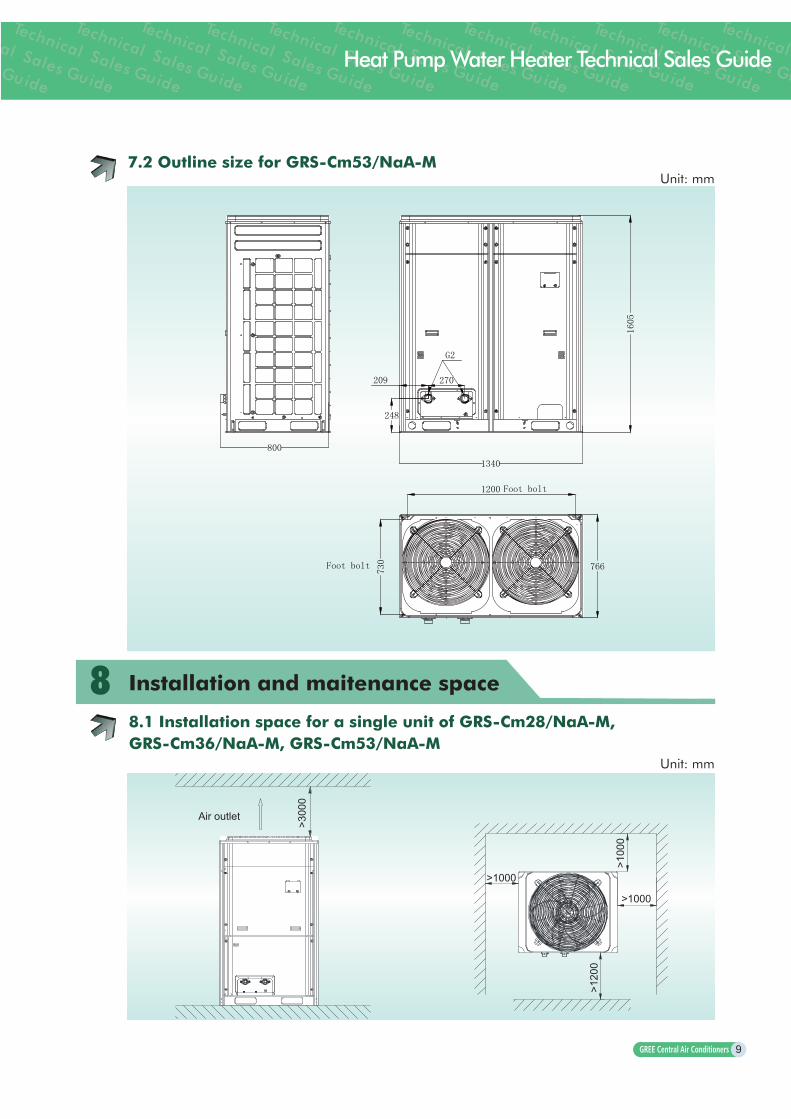
7.2 Outline size for GRS-Cm53/NaA-MUnit: mm
88.1 Installation space for a single unit of GRS-Cm28/NaA-M, GRS-Cm36/NaA-M, GRS-Cm53/NaA-M
Installation and maitenance space
Unit: mm
Air outlet
>300
0
>100
0
>120
0
>1000
>1000

10
8.2 Installation space for modular units of GRS-Cm28/NaA-M,GRS-
Cm36/NaA-M,GRS-Cm53/NaA-MUnit: mm

11
Heat Pump Water Heater Technical Sales Guide
9 Electric installation
1.All electric installation must be performed by professional person according to local law, regulation and instruction manual.
2.All installation must be check before putting through power. 3.Please adopt rated voltage and special power for the water heater. 4.Power cord should be fixed reliably. 5.When power cord and connection wire are damaged, please replace it with special electric
cable. 6.For the consideration of safety, customer should install the leakage protection device at the
power side. The detailed position is as below:
Selection of Air Switch and Power Cord
Unit model Power type
Minimum sectional area of power cord(mm2) Capcity of air switch(A)
Live wire Neutral wireEarthing
wire
GRS-Cm/28NaA-M 380-415V 3N ~ 50Hz 2.5 2.5 2.5 25
GRS-Cm/36NaA-M 380-415V 3N ~ 50Hz 4 4 4 32
GRS-Cm/53NaA-M 380-415V 3N ~ 50Hz 6 6 6 40
1.Fuse and power cord are selected according to the maximum power (maximum current) of the unit.
2.If the length of power cord is more than 15m, please increase the sectional area of power cord properly to prevent accident.
3.Heat pump water heater belongs to type I electric appliances. Please adopt reliable grounding measures.
4.The yellow-green wire of the unit is the earthing wire. Please do connect the earthing wire to below places:
a. tap water pipe b. gas pipe c. blow-off pipe d. other reliable places.
10
Project electric cabinet
Leakage protection device
Leakage protection device Leakage protection device Leakage protection device
Hot water 1 Hot water 2 Hot water n

12
Annex Model Selection and Installation for theCommercial Water Heater in Project Design
1 Model selection of water heater
2 Model selection of water pump
Hot water projectCalculate the hot water volume according to actual requirement. According to local lowest average temperature and the water inlet temperature of water heater
in the coldest season, view table or curve to get the actual water generation capacity of water heater. Meanwhile, other factors should be considered. Calculate the hot water generation volume under the condition that water heater works for 10-14 hours a day. The how water requirement for the building should be satisfied even in the bad working condition.Decide the unit mode and quantity according to the size of installation position, weight bearing factor, and so on.
Selection of flow volume of hot water circulating water pump and delivery liftFlow volume requirement should satisfy the rated flow volume of hot water. When the unit and
the water tank is are installed at the same floor, the rated delivery lift of water pump should be 15m above.Selection of the hot water supply pressure pump at user side
In general, the water supply pressure pump will adopt normal pressure pump, self-feeding automatic start-stop pump or electric contact pressure switch+circulating pump. For large scale project, the inverter water pump will be adopted for the comfort of water generation.
The detailed model selection can’t be regulated clearly, which should be decided by actual product. Delivery list H is 1.1~1.2 times of the sum of height difference between hot water outlet of water tank and terminal pipeline, resistance loss along the pipeline and part resistance loss. Resistance loss along the pipeline and part resistance loss should be calculated by the water power. When calculating the delivery lift, take 50.5kPa water column for the part resistance loss, and 5m every 100m pipe for the resistance loss along the pipeline. If the pipeline is L, the delivery lift should be calculated by below formula:
H=(5+Z+0.05L)×1.1 or 1.2The flow volume of water pump is the 1.3 times of the flow volume of system at the peak time of
water consumption.
Note
The lift calculated by above formula is lift of water pump used for overcoming the water resistance. If it needs to add pressure, the lift should add 15m~25m.

13
Heat Pump Water Heater Technical Sales Guide
GRS-Cm28/NaA-M
Quantity of unitMian water inlet
pipeMain water outlet
pipeCirculating water pump (rated value)
1 set DN40 DN40 Q>4.8m3/h H is calculated by the formula
2 sets DN50 DN50 Q>9.6m3/h H is calculated by the formula
3 sets DN65 DN65 Q>14.4m3/h H is calculated by the formula
4 sets DN65 DN65 Q>19.2m3/h H is calculated by the formula
GRS-Cm36/NaA-M
Quantity of unitMian water inlet
pipeMain water outlet
pipeCirculating water pump (rated value)
1 set DN50 DN50 Q>6.2m3/h H is calculated by the formula
2 sets DN65 DN65 Q>12.4m3/h H is calculated by the formula
3 sets DN80 DN80 Q>18.6m3/h H is calculated by the formula
4 sets DN100 DN100 Q>24.8m3/h H is calculated by the formula
GRS-Cm53/NaA-M
Quantity of unitMian water inlet
pipeMain water outlet pipe Circulating water pump (rated value)
1 set DN65 DN65 Q>9.2m3/h H is calculated by the formula
2 sets DN80 DN80 Q>18.4m3/h H is calculated by the formula
3 sets DN100 DN100 Q>27.6m3/h H is calculated by the formula
4 sets DN125 DN125 Q>36.8m3/h H is calculated by the formula
Note
The “circulating water pump” in above table indicated hot water circulating water pump.

14
3 Selection of water pipe
Hot water supply pipe, hot water circulating pipe, water makeup pipe and drainage pipe should adopt PPR pipe, compound pipe, galvanized steel pipe and copper pipe.
For consideration of the problem of extension and clean of pipeline, PPR pipe is suggested for the installation. PPR is with good heat resistant performance (applicable temperature range -20 120°C).
The suggested specification for the PPR pipe is in below table:
Formula: V=Q/SV——Water flow speed ; Q——Rated flow volume of unit;S——Sectional area for the water connection pipe;
Model selection of inlet/outlet/water pipe for GRS-Cm28/NaA-M
Quantity of unit Mian water inlet pipe Main water outlet pipe
1 set DN40 DN40
2 sets connection in parallel DN50 DN50
3 sets connection in parallel DN65 DN65
4 5 sets connection in parallel DN80 DN80
6 8 sets connection in parallel DN80 DN80
9 14 sets connection in parallel DN100 DN100
15 16 sets connection in parallel DN100 DN100
Model selection of inlet/outlet/water pipe for GRS-Cm36/NaA-M
Quantity of unit Mian water inlet pipe Main water outlet pipe
1 set DN50 DN50
2 sets connection in parallel DN65 DN65
3 sets connection in parallel DN80 DN80
4 5 sets connection in parallel DN100 DN100
6 8 sets connection in parallel DN100 DN100
9 14 sets connection in parallel DN125 DN125
15 16 sets connection in parallel DN125 DN125
Model selection of inlet/outlet/water pipe for GRS-Cm53/NaA-M
Quantity of unit Mian water inlet pipe Main water outlet pipe
1 set DN65 DN65
2 sets connection in parallel DN80 DN80
3 sets connection in parallel DN100 DN100
4 5 sets connection in parallel DN125 DN125
6 8 sets connection in parallel DN150 DN150
9 14 sets connection in parallel DN150 DN150
15 16 sets connection in parallel DN200 DN200

15
Heat Pump Water Heater Technical Sales Guide
Note
1.As for multiple units’ connection in parallel for operation, after selecting the main water pipe, the water power must be calculated. If the pipeline resistance at water side is more than the delivery list of selected water pump, it needs to select the bigger water pump again, or increase the water pipe.
2.If adopt steel pipe, copper pipe and other metal pipes for the pipeline, the unit must connect PPR connection pipe, and then connect metal pipes through connection pipe sub-assy.
3.The water pipe should be installed uprightly and the layout the pipelines should be reasonable for reducing elbows as much as possible.
4.Strainer should be installed at the water inlet of unit for preventing blockage of water side heat exchanger.
5.In general, service valve should be installed in front of the solenoid valve for future maintenance. For the clean of system, drainage valve should be installed at the lowest position of the system, and discharge valve should be installed at the highest position of the system.
6.When the pipeline is installed well, leakage test must be performed according to related regulation. The pipeline should be clean for preventing damage to heat exchanger and water pump.
7.After that, water inlet pipe, water outlet pipe and water makeup pipe should be thermal insulated to preventing heat loss and breakage of pipeline in winter. All valves should also be thermal insulated.

Add: West Jinji Rd,Qianshan Zhuhai,Guangdong,China519070Tel: (+86-756)8614883 Fax: (+86-756)8614998Http://www.gree.com Email: [email protected] continous improvement in the products, Gree reserves the right to modify the product specification and appearence in this manual without notice and without incurring and obligations.
Gree Electric Appliances, Inc. of Zhuhai, founded in 1991, is the world's largest air
conditioner enterprise integrating R&D, manufacturing, marketing and services.
Technology Innovation and quality are always our priority. With efforts of
thousands of Gree's engineers, we own more than 3500 patents for our products.
Nowadays, we have 7 production bases in Zhuhai, Chongqing, Hefei and
Zhengzhou(China), as well as Brazil, Pakistan and Vietnam, with annual
production capacity of 30 million sets of residential air conditioners and 4 million
sets of commercial air conditioners.
With the installation of Gree commercial air conditioners in important projects at
home and abroad like Media Village for 2008 Beijing Olympic Games, Stadiums
for 2010 World Cup in South Africa, as well as India Telecom base station, Gree
commercial air conditioners are ready to develop steadily to every corner in the
world, to present a more comfortable and harmonious working environment and
family atmosphere.
REE MAKING BETTER CONDITIONERS GREE MAKING BETTER CONDITIONERS GREE MAKING BETTER CONDITIONERS GREE MAKIN
SJ00434333