Ultra Low Profile and High Power ! Programmable DC Power Supply 2021. 7. 2. · re250-35 re300-2.5...
12
NEW NEW www.matsusada.com High power Variable DC power supply RE Series Analog control / High power DC power supplies Remote control is also available via various interfaces The best model is selectable with wide lineup Ultra Low Profile and High Power ! Programmable DC Power Supply RE series Max. output voltage 10 V to 1 kV Max. output current 1.2 A to 1.2 kA Max. output power 750 W to 15 kW
Transcript of Ultra Low Profile and High Power ! Programmable DC Power Supply 2021. 7. 2. · re250-35 re300-2.5...

NEWNEW
www.matsusada.com
High power Variable DC power supplyRE Series
Analog control / High power DC power supplies
Remote control is also available via various interfaces
The best model is selectable with wide lineup
Ultra Low Profile and High Power !Programmable DC Power Supply
RE series
USA/Canada : +1-888-652-8651other countries : +81-6-6150-5089FAX
Max. output voltage
10 V to 1 kV
Max. output current
1.2 A to 1.2 kA
Max. output power
750 W to 15 kW
REseries
USB
RS-232C
LAN
RS-485
GPIB
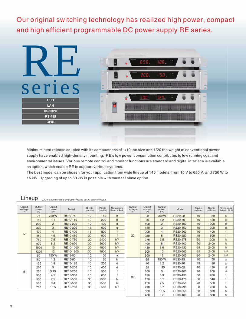
Our original switching technology has realized high power, compact
and high efficient programmable DC power supply RE series.
Minimum heat release coupled with its compactness of 1/10 the size and 1/20 the weight of conventional power
supply have enabled high-density mounting. RE's low power consumption contributes to low running cost and
environmental issues. Various remote control and monitor functions are standard and digital interface is available
as option, which enable RE to support various systems.
The best model can be chosen for your application from wide lineup of 140 models, from 10 V to 650 V, and 750 W to
15 kW. Upgrading of up to 60 kW is possible with master / slave option.
Lineup (UL marked model is available. Please ask to sales offices.)
10
15
750 W1.1234
4.57.58.21012
750 W1.21.83
3.754.57.58.4
10.5
150220400600800900
2400360048004800100160250400500600
250025003500
10101015153020303030101010101515303035
bbddff
h*2
h*2
h*2
h*2
abddffhh
h*2
RE10-75RE10-110RE10-200RE10-300RE10-400RE10-450RE10-750RE10-820RE10-1000RE10-1200RE15-50RE15-80RE15-120RE15-200RE15-250RE15-300RE15-500RE15-560RE15-700
75110200300400450750820
100012005080120200250300500560700
20
30
760 W1.22345
7.58
8.61012
750 W1.21.95
33.95.17.58.710.512
80120200300400500
12002400240024002400
5080
130200260340500700800800
101010151015302035353010152020303020303020
aaddffhhh
h*2
h*2
aaddfffhhh
RE20-38RE20-60RE20-100RE20-150RE20-200RE20-250RE20-375RE20-400RE20-430RE20-500RE20-600RE30-25RE30-40RE30-65RE30-100RE30-130RE30-170RE30-250RE30-290RE30-350RE30-400
3860100150200250375400430500600254065100130170250290350400
Outputcurrent
(A)
Outputpower(kW)
Model Ripple(mVrms)
Ripple(mArms)
Outputvoltage
(V)
Dimensions(Refer to P8,9)
Outputcurrent
(A)
Outputpower(kW)
Model Ripple(mVrms)
Ripple(mArms)
Outputvoltage
(V)
Dimensions(Refer to P8,9)
*1*1
02

*1*2*3*4
Rated output current when output voltage is 10 % to 100 % of rationg.Height and number of fixing holes of busbar are different depending on the model.See P7 for details.To be released soon.Please contact our sales office.
35
40
45
60
80
100
150
160
770 W1.22.134
4.97.58.410.511.9
48.8
765 W1.22345
7.59.911.7
750 W1.22.1345
7.58.410.212
13.2158.8
750 W1.22345
7.58.41015
750 W1.22.1345
7.58.410.5154.38.8
5070
120170230280
1800200020002400300350406090
130180220750
11001300
254070
100135170350350500500500500600
1525406080
100300350800
1000102030405570
100100200200
55200
101020202030353535353030181830303045454545202015202030303035353525802020203030406060100100303025303060707015010030160
aaddfffhhhfhaacdfffhhaaccfffhhhhhhaacceefhhhaacceeeghheg
aacceeeghhgaacceeegggegggggggaacceeegggegaacceeeggg*4*4*4*4
RE35-22RE35-34RE35-60RE35-85RE35-115RE35-140RE35-215RE35-240RE35-300RE35-340RE40-100RE40-220RE45-17RE45-27RE45-45RE45-66RE45-90RE45-110RE45-165RE45-220RE45-260RE60-12.5RE60-20RE60-35RE60-50RE60-67RE60-83RE60-125RE60-140RE60-170RE60-200RE60-220RE60-250RE80-110RE100-7.5RE100-12RE100-20RE100-30RE100-40RE100-50RE100-75RE100-84RE100-100RE100-150RE150-5RE150-8RE150-14RE150-20RE150-27RE150-33RE150-50RE150-56RE150-70RE150-100RE160-27RE160-55
760 W1.22345
7.48.410158.7
750 W1.223
3.94.87.58.410.515
7.358.49.814.77.5157.515
750 W1.22345
7.58.510157.515
780 W1.22
2.93.95
7.28.810.4157.5157.515
40404040
20020020015020020010050505050
300300100100300150150150150150200200200200150150150150500500200200500200100100200200200200200200200250250300300300300300
200
250
300
350
400
450
500
600
650
750
1000
3.861015202537425075352.54
6.51013162528355021242842
18.737.516.733.31.52.44681015172030
12.5251.21.83
4.56
7.711
13.5162310207.515
101520304050
280200380530150
510152030355050
10010010010010010010010050
10055
101520205050
1001002550
55
10101520505050
10030503050
RE200-3.8RE200-6RE200-10RE200-15RE200-20RE200-25RE200-37RE200-42RE200-50RE200-75RE250-35RE300-2.5RE300-4RE300-6.5RE300-10RE300-13RE300-16RE300-25RE300-28RE300-35RE300-50RE350-21RE350-24RE350-28RE350-42RE400-18.7RE400-37.5RE450-16.7RE450-33.3RE500-1.5RE500-2.4RE500-4RE500-6RE500-8RE500-10RE500-15RE500-17RE500-20RE500-30RE600-12.5RE600-25RE650-1.2RE650-1.8RE650-3RE650-4.5RE650-6RE650-7.7RE650-11RE650-13.5RE650-16RE650-23RE750-10*3
RE750-20*3
RE1000-7.5*3
RE1000-15*3
22346085
1151402152403003401002201727456690
11016522026012.52035506783
1251401702002202501107.5122030405075841001505814202733505670
1002755
Outputcurrent
(A)
Outputpower(kW)
Model Ripple(mVrms)
Ripple(mArms)
Outputvoltage
(V)
Dimensions(Refer to P8,9)
*1 Outputcurrent
(A)
Outputpower(kW)
Model Ripple(mVrms)
Ripple(mArms)
Outputvoltage
(V)
Dimensions(Refer to P8,9)
*1
03

Output control
Voltage regulation
Current regulation
Stability
Temperature coefficient
Output display
Monitor output
Protections
Other functions
Transient response time
Operation temperature
Storage temperature
Strage humidity
Dielectric voltage
Accessories
Specifications
Local : Constant voltage : 10-turn potentiometer on front panel Constant current : 10-turn potentiometer on front panelRemote : Constant voltage : external control voltage 0 to 10 Vdc or external variable resistor 0 to 10 k Constant current : external control voltage 0 to 10 Vdc or external variable resistor 0 to 10 k
Line : 0.1 % of maximum output (for AC±10 % input change)Load : 0.1 % of maximum output (for 10 % to 100 % load change) (for only RE10-1000and RE10-1200, load regulation is 0.15 %)
Input : 0.1 % of maximum output (for AC±10 % input change)Load : 0.1 % of maximum output (for 10 % to 100 % load change) (for only RE500-1.5, -2.4,650-1.2, -1.8, both line and load regulation are 0.2 %)
0.05 % / 8 Hr of maximum output voltage
0.02 % / °C of maximum output voltage0.03 % / °C of maximum output current
Output voltage : 3-digit digital meter (accuracy is 1 %FS ±1 dgt)Output current : 3-digit digital meter (accuracy is 1 %FS ±1 dgt)
Output voltage monitor : 10 V / maximum output voltageOutput current monitor : 10 V / maximum output current
Over voltage protection (OVP) Output is cut off at a set value. Setting range : 5 % to 110 % of output voltage Local setting : 1-turn volume on front panel Remote setting : External control voltage of 0 to 10 Vdc Reset : Manual recovery by OUTPUT switch or remote switch.
Over temperature protection (OTP) Output is cut off when internal part is heated abnormally. Reset (after the temperature has gone down to normal) : Automatic recovery or manual recovery by POWER switch (selectable).
Input brownout(ACF) · Blackout protection Output is cut off when input decreased by 20 % or more. Reset (when normal voltage value or recovery from blackout) : Manual recovery by OUTPUT switch for blackout protection (re-output protection function). : Automatic recovery when blackout protection is canceled.
Remote sensingRemote switch ON / OFF (TTL or external relay)Status signal output (CV, CC, FLT)
Recovery time 1 ms (for 70 % 100 % load change)
0 to +50 °C (750 W to 5.1 kW)0 to +40 °C (7.35 kW to 15 kW)
-20 °C to +70 °C
20 % to 80 % RH (no condensation)
Between input power supply and power supply, and between output terminals and chassis is AC1500 V : 1 minute
· 2.5 m input AC cable for single phase, 3-pin type (only models of 2.1 kW or less) (1) (AC input cable for three-phase is not attached. Please contact our sales office if any cable is needed.)
· Instruction manual (1)
· Remote connector cover (1)
· Metal fitting to change input voltage (1) (up to 1.2 kW models only)
Single phase AC input cable (3-pin type)
Three-phase AC input cable
25 A / 250 V single phase flying leadModel CABLE TYPE 5 : Standard 2.5 m length CABLE TYPE 5( ) : Extended length(2.5 m increment)
25 A / 250 V for 1.8 kW to 3 kW models, flying leadModel CABLE TYPE 675 A / 250 V for more than 3.75 kW models, flying leadModel CABLE TYPE 7
<e.g.> 5 m : CABLE TYPE 5(5)
separate
04
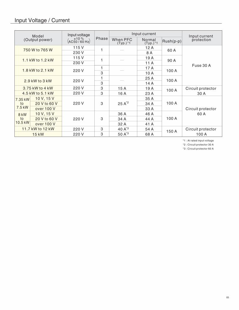
Input Voltage / Current
750 W to 765 W
1.1 kW to 1.2 kW
1.8 kW to 2.1 kW
2.9 kW to 3 kW
3.75 kW to 4 kW4.5 kW to 5.1 kW
10 V, 15 V20 V to 60 Vover 100 V10 V, 15 V20 V to 60 Vover 100 V
115 V230 V115 V230 V
220 V
220 V
220 V220 V
220 V
220 V
220 V220 V
1
1
131333
3
3
33
60 A
90 A
100 A
100 A
100 A
100 A
100 A
150 A
15 A16 A
25 A
36 A34 A32 A40 A50 A
8 kWto
10.5 kW
12 A8 A
19 A11 A17 A10 A25 A14 A19 A23 A35 A34 A33 A46 A44 A41 A54 A68 A
7.35 kWto
7.5 kW
PhaseModel
(Output power)Input voltage
±10 %AC50 / 60 Hz
Input current
Rush(p-p)When PFC(Typ.)
Normal (Typ.)
Input current protection
*1 : At rated input voltage
*2 : Circuit protector 30 A
*3 : Circuit protector 60 A
11.7 kW to 12 kW15 kW
Circuit protector 30 A
Fuse 30 A
Circuit protector 60 A
Circuit protector 100 A
*1 *1
*2
*3
*3
05
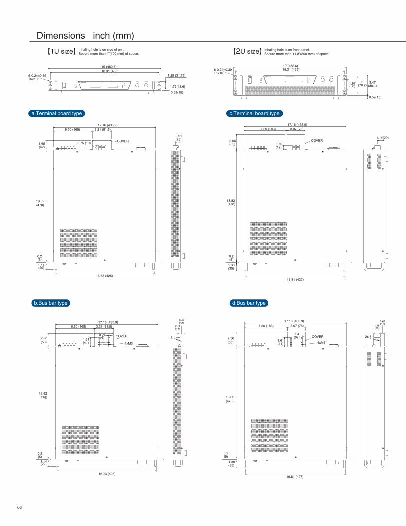
Dimensions inch (mm)
COVER
O
I
I
O
19 (482.6)
6-0.24×0.39(6×10)
6-0.24×0.39(6×10)18.31 (465)
0.59(15)
17.16 (435.9)6.50 (165) 3.21 (81.5)
16.73 (425)
17.16 (435.9)7.20 (183) 3.07 (78)
0.75(19)
0.75 (19)
1.14(29)
0.67(17)
1.18(30)
16.81 (427)
17.16 (435.9)6.50 (165)
1.61(41)
1.61(41)
0.24(6)
3.21 (81.5)
0.47(12)
0.71(18)
19 (482.6)18.31 (465)
0.59(15)
a.Terminal board type
b.Bus bar type d.Bus bar type
【1U size】Inhaling hole is on side of unit.Secure more than 4”(100 mm) of space.
c.Terminal board type
16.73 (425)
17.16 (435.9)7.20 (183)
0.24(6)
3.07 (78)
16.81 (427)
Inhaling hole is on front panel.Secure more than 11.8”(300 mm) of space.【2U size】
0.91(23)
1.72(43.6)
1.25 (31.75)
1.65(42)
18.82(478)
0.2(5)
0.2(5)
1.14(29)
0.2(5)
1.14(29)
2.56 (65)
18.82 (478)
1.38(35)
0.2(5)
1.38(35)
3.47(88.1)
3(76.2)1.97
(50)
COVER
4xM3
COVER
4xM3
COVER2.28(58)
18.82 (478)
8 2x 82.56 (65)
18.82 (478)
06

All models have exhaust hole for forced air cooling on rear panel.When mounting on a cabinet where a space of1.18”(300 mm) ormore cannot be secured, please arrange a measure such as forced draft vent.
Inhaling hole is on front panel.Secure more than 11.8”(300 mm) of space.【3U size】
e.Terminal board type
f.Bus bar type
CURRENTVOLTAGE
SET
OVP
REGULATED DC POWER SUPPLY
POWER
OUTPUT
0.59(15)
19 (482.6)
6-0.24×0.39(6×10)
18.31 (465)
5.22 (132.5)
3.94 (100)
2.25(57.15)
17.14 (435.4)
10.26 (260.5) 3.46 (88)
0.75(19)
1.13(28.6)
16.81 (427)
COVER
2.56(65)
18.82(478)
0.2(5)
1.38(35)
17.14 (435.4)
10.26 (260.5) 3.46 (88)
1.61(41)
0.24(6)
0.69(17.6)1.97
(50)
16.81(427)
2.56(65)
18.82(478)
0.2(5)
2xM3
COVER
1.38(35)
3x8
(*) Height of busbars is 3.86”(98mm),number of holes is 6 for RE10-750,RE 10-820,RE10-1000,RE10-1200,RE15-700,RE20-500 and RE20-600.
17.14 (435.4)
10.26 (260.5) 3.46 (88)
1.61(41)
0.24(6)
1.97(50)*
16.81 (427)
g.Terminal board type
h.Bus bar type
17.14 (435.4)
10.26 (260.5) 3.46 (88)
0.75(19)
1.13(28.6)
16.81 (427)
COVER2.56(65)
28.82(605)
0.2(5)
1.38(35)
2.56(65)
28.82(605)
0.2(5)
1.38(35)
COVER
2xM3
3x8*
0.69(17.6)
07

POWER ON/OFF switch: This has priority over all operations for safety reasons.
OUTPUT ON/OFF switch: This is used for urgent OFF or resume output in remote mode as well output ON/OFF in local mode. Also used for resetting protection function.
OUTPUT ON display LED
Remote programming display: This lights up during remote control of voltage or current.
External switch OFF display
Fault display (FLT): This lights up when OVP, OTP or ACF has occurred.
Remote enable display: This lights up when controlling by built-in interface board.
Operation mode (constant voltage or constant current)
Output preset switch: This is pressed down when output is being set by digital meter and output setting knob, then OUTPUT switch is turned ON to output.
OVP setting switch
OVP setting volume: This volume sets OVP setting value that is displayed on voltmeter when is pressed down.
Communication status display (only when interface board is built in)
Only when option·USB/RS-232C / RS-485 / GPIB interface board·Isolate remote program board
Exhaust hole
AC input connector (M4) M6 type for model over 3.75 kW
GND terminal (M4)
⑰
Output voltage setting dial (10-turn)
Output voltage meter (Also for OVP setting display) Output current meter
Output current setting dial (10-turn)① ② ③ ④ ⑤⑥ ⑦ ⑧⑨⑩⑪⑫
⑬
⑭
⑮ ⑯
Front
Function setting switch (SW1) Remote sensing Output terminal
Remote control connector (TB1)
The form differs depending on the MODEL.Please check which form in Dimension.
+
-
+S
-S
Io
Load
VLVoOUTPUT
R
Prevents voltage drop down (VO-VL) due resistance (R) or deterioration of stability by contact resistance (Max 0.5V)
*Please use TB1 in floating as TB1 and minus output is connected in the internal part.
Remote / Local change
5 V
or+
- Vout
0 to MAX
RVcon
0 to approx.10 kMAX 1 mA
0 Vdc to 10 VdcInput imp.500 k
TB1-S(common)
5 V
or+
-TB1
-S(common)
+
OVP TB1-S(common)
ImoniVVmoniVTB1-S(common)
Output relay
SHORT
OPEN
TTL
LOW
HIGH
MODE
Remote
Local
+
orCV TB1-S(common)
Iout
0 to MAX
RIcon
0 to approx.10 kMAX 1 mA
0 Vdc to 10 VdcInput imp.500 k
+
orCC TB1-S(common)
Each of voltage, current, OVP or all the modes can be switched by relay or TTL signal
Output control
Remote switch ON / OFF
Output relay
SHORT
OPEN
TTL
LOW
HIGH
Output can be turned ON/OFF by relay or TTL signal. Logic of signal can be selected by entering 5 V.
Output monitor
Status outputCommon is floating in open collector output of common that is common to each. Withstanding voltage 30 Vdc. Sink current 5 mA or less.
Vmax×5 to 110 %
0 Vdc to 10 VdcInput imp.20 k
0 Vdc to 10 VdcOutput imp.1 k
0 Vdc to 10 VdcOutput imp.1 k
Output0 to MAX
Turn on when OVP, OTP, ACF
Turn on wheneach status.
COM
FLTCV
CCTB1
Voltage control0 V to 10 V Local 0 to 10 kapprox.
Current control0 V to 10 V Local 0 to 10 kapprox.
Blackout protectionON OFF(ON / OFF by AC)
Over temperature protectionManual reset Auto reset
Terminal boardoutput type
Bus bar output type
Output terminal cover
Terminal boardoutput type
Bus bar output type
Output terminal cover
Rear
Functions
To an output terminal cover for terminal board models, two places of holes of 8mm in diameter are arranged as standard specifications.A diameter bigger than 8 mm is also available.Please contact our sales office for details.
08

*Please ask sales offices for Three-phase input AC cable.
*1. These options cannot be selected together. Only one of each can be selected. And, when you connect “Load”, “RE series” and “PC”, if you prevent the influence on the PC by the noise that occurred with load, please choose -LGob option. With that in mind, we recommends using it combining our adapter (separated item).*2. Ethernet is a registered trademark of Xerox Corporation. *3. This option cannot be chosen simultaneously with -LGob, -LUs1, -LEt, -LGb or –LIs / -LIs10. However, in being required, please contact our sales office. But, this option cannot be chosen simultaneously with –LOcp or –LMs.*4. This option cannot be chosen simultaneously with –LCp.*5. -LPfc and -L(400V) cannot be chosen simultaneously.
<e.g> RE15-250-LGob(Fc5)LpPfc(240V)<e.g> RE100-100-LCpIs10LpOcp(400V)
Output control
Monitor output
Other functions
[-LIs]CV : External control voltage 0 to 5 VdcCC : External control voltage 0 to 5 Vdc[-LIs10]CV : External control voltage 0 to 10 VdcCC : External control voltage 0 to 10 Vdc
[-LIs]Output voltage monitor : 5 V / Maximum output voltageOutput current monitor : 5 V / Maximum output current[-LIs10]Output voltage monitor : 10 V / Maximum output voltageOutput current monitor : 10 V / Maximum output current
[-LIs / -LIs10]Remote switch ON / OFF, status signal output (CC, OUTPUT and Stand-by)
CO-opt Cable
GPIB enablescontrol of up to14 CO-G32modules.
32 units can beconnected to 1 CO-G32.
CO-G32
CO-OPT2-25CO-OPT2-9CO-OPT4-25
32 units can be connected to 1 CO-U32.
CO-U32
32 units can be connected to 1 CO-E32.
CO-E32
A
A
A
A
Can beextended via hub
Can beextended via hub
RS-232CRS-485
LAN(Ethernet)
USB
GPIB
Isolated remote control *1
···Output control signal is isolated from common(=output ) so that floating of control signal is not required when negative output operation or series connection (isolation voltage from output is below 250 V)
-LLp
-LPfc
-L(220V)
-L(230V)
-L(400V)
-Lls /-LIs10
10-turn potentiometer with lock (both voltage and current) ···only for models less than 300 V
Power factor correction circuit (Three-phase input of 3.75 kW to15 kW type only)*5
Size of the case will be different. Contact nearby salesoffice for more details for this option.
Input voltage : 220 VAC±10 %For 750 W to 1.2 kW modelsInput current will be about 105 % of typical value( P.5).
Input voltage : 230 VAC±10 %For 1.8 kW to 15 kW modelsInput current will be about 95 % of typical value( P.5).
Input voltage : 240 VAC±10 %For all models[The models that original input voltage is 230 V] Input current will be about 95 % of typical value( P.5).[The models that original input voltage is 220 V] Input current will be about 90 % of typical value( P.5).
Input voltage : 400 VAC±10 %For 7.5 kW to 15 kW modelsSize of the case will be different. Contact nearby salesoffice for more details for this option.
Add above -L mark to the model number when ordering
alphabetical, number order.
Options
-LGob : Optical Interface Board + 2 meters long optical cable-LGob(Fc5) : Optical Interface Board + 5 meters long optical cable-LGob(Fc10) : Optical Interface Board + 10 meters long optical cable-LGob(Fc20) : Optical Interface Board + 20 meters long optical cable-LGob(Fc40) : Optical Interface Board + 40 meters long optical cable
It is isolated by optical communication. It makes it possible to prevent malfunction caused by transient phenomenon such as surge, lightning, induction, and external noise due to perfectly isolated by optical fiber.
In case power supply will be use following condition, make sure this options selected. ・Noisy environment such as factories. (ex. usage of motor and coil around load or power supply) ・Usage on high voltage floating (more than 250 V) ・In case the distance between power supply and controller (PC or PLC) is longer than 2-meter long.
-LGob : Optical Interface Board *1
Various adapters(Separately sold)
hub
hub
Terminal boardoutput type
Bus bar output type
Output terminal cover
GPIB interface board *1
Constant power control *3
(Voltage control is eliminated.Limited at maximum rated voltage)
USB interface board *1
Ethernet interface board *1
-LUs1
-LEt
-LGb
-LCp
-L(240V)
Over current protection (OCP)*4
Cut off the output at set current value.Local setting only.Setting range : 5 % to 110 % of maximum rated currentLocal setting : 1-turn volume on front panelReset : Manual recovery by OUTPUT switch or remote swich
-LOcp
09

Introduction of other DC Power Supplies
Output voltageOutput currentOutput power
0 to 800 V0 to 180 A400 W, 800 W, 1.2 kW
Output voltageOutput currentOutput power
0 to 650 V0 to 130 A800 W
Output voltageOutput currentOutput power
0 to 1000 V0 to 6000 A20 kW to 120 kW
Output voltageOutput currentOutput power
0 to 1500 V0 to 1200 A1.3 kW to 15 kW
Output voltageOutput currentOutput power
0 to 40 V0 to 4 A0.2 W to 36 W
0 to1.2 kV0 to 20 A1.1 kW to15 kW
Output voltageOutput currentOutput power
Customization is also available.Please contact our sales office.We accept the consultation about the delivery date.
R4K-36 series
RK series
REKJ series
REK series
REH series
REM series
Ultra slim palm-sizedDC power supply
Desk-top size high powerDC power supply
Ultra compact low profileDC power supply
Low profile high powerDC power supply
High power high voltage DC power supply
High-capacity DC power supply
The models which set and output the current with the 0.1 mAincrement are available.High resolution D/A, A/D converter integrated.USB interface is also available.
2U / 3U compact unit with high power output 5.5 kW / 15 kW.Various operations by connecting multiple power supplies, such as master/slave, is possible.Operability and safety are improved with new features.
(except some models)(available by option)
Low noise, multiple functions, and digital communication.PFC circuit and universal input wound not select the place of operation.The sequence function enables the user to control the supplywithout a laptop option.
The compact half rack and 1U low profile design.Ideal for research and development with low noise switching method.The sequence function enables the user to control the supplywithout a laptop option.
2U / 3U compact unit with high
Ultra low profile and space-saving design with 3.5", 5.2" height.Extensive safety design from high voltage experience and technology.Well suited for solar cell characteristic evaluation and powerconditioner evaluation.
The device that is also dividable for use is efficient for variousdifferent applications.Extendable up to 360 kW, the device is suitable for casesrequiring larger output.
Click [List]!Click [List]!
The compact half rack and 1U lo
10
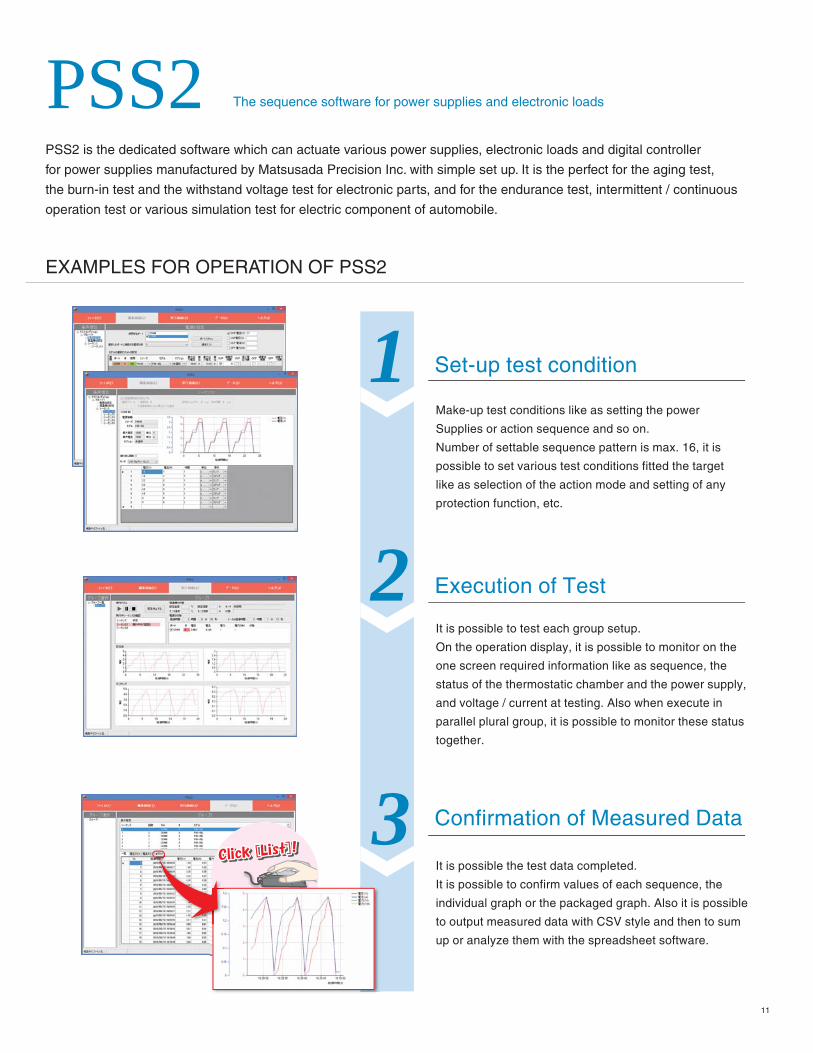
PSS2 is the dedicated software which can actuate various power supplies, electronic loads and digital controller
for power supplies manufactured by Matsusada Precision Inc. with simple set up. It is the perfect for the aging test,
the burn-in test and the withstand voltage test for electronic parts, and for the endurance test, intermittent / continuous
operation test or various simulation test for electric component of automobile.
PSS2 The sequence software for power supplies and electronic loads
Set-up test condition
Make-up test conditions like as setting the power
Supplies or action sequence and so on.
Number of settable sequence pattern is max. 16, it is
possible to set various test conditions fitted the target
like as selection of the action mode and setting of any
protection function, etc.
It is possible to test each group setup.
On the operation display, it is possible to monitor on the
one screen required information like as sequence, the
status of the thermostatic chamber and the power supply,
and voltage / current at testing. Also when execute in
parallel plural group, it is possible to monitor these status
together.
It is possible the test data completed.
It is possible to confirm values of each sequence, the
individual graph or the packaged graph. Also it is possible
to output measured data with CSV style and then to sum
up or analyze them with the spreadsheet software.
Execution of Test
Confirmation of Measured Data
EXAMPLES FOR OPERATION OF PSS2
1
2
3Click [List]!Click [List]!Click [List]!Click [List]!Click [List]!
11

01.158.05 74
NEWCustomer Inquiry Sheet ( RE series )Please copy this page and above fax number after filling out form below.
A quotation
Other ( )
An explanation of product A demonstration To purchase
Address:
Company:
Dept.: Title:
Fax:
Name:
Tel:
E-mail:
Give us your requirement / comment
I would like
Please fill in below.
USA/CanadaUSA/Canada : : + +1-888-652-86511-888-652-8651other countriesother countries : : +81-6-6150-5089+81-6-6150-5089FAXFAX
We warrant the specification, unless otherwise specified, at max. rated output after warm up, and scope of application is between 10 % and 100 % of max. rated output. We warrant that products contained in this catalog (hereinafter, the “Products”) are free from defects in material and workmanship under normal use for a period of one (1) year from the date of shipment thereof. However, the warranty period for X-ray detectors and X-ray source shall be either one (1) year from the date of shipment or 1,000 hours, whichever shorter. The above warranty shall not apply to any Product which, at our sole judgment, has been: i) Repaired or altered by persons unauthorized by us; or ii) Connected, installed, adjusted or used otherwise than in accordance with the instructions furnished by us (including being used in an inappropriate installation environment, such as in corrosive gas, high temperature and humidity). We are not liable for any loss, damage or failure of the Products after the shipment thereof caused by external factors such as disasters. We will not inspect, adjust or repair any of our power supply products in the field or at any customer site. If you suspect that there has been a power supply failure in the field, please inspect your whole unit by yourself in an effort to determine that the problem is, in fact, arising out of our power supply products. If it is found that the problem is arising out of such power supply product after inspection, please contact your local sales office for additional troubleshooting. A “Return Merchan-dise Authorization” is required in case the power supply must be sent back to the factory in Japan for inspection and repair. We, at our sole discretion repair or replace such defective products at no cost to the purchaser. We assume no liability to the purchaser or any third party for special, incidental, consequential, or other damages resulting from a breach of the foregoing warranty. This warranty excludes any and all other warranties not set forth herein, express or implied, including without limitation the implied warranties of merchantability or fitness for a particular purpose. The Products are not designed and produced for such applications as requiring extremely high reliability and safety, or involving human lives (such as nuclear power, aerospace, social infrastructure facility, medical equipment, etc.). The use under such environment is not covered by this warranty and may require additional design and manufacturing processes. No modification or supplement of this warranty shall be binding unless in writing and signed by a duly authorized officer of Matsusada. Matsusada reserves the right to make any changes in the contents of catalogs or specifica-tions at any time without advance notice. Due to compelling reason such as unavailability of components used, products might be un available or unable to repair. The products specified in catalogs or specifications are designed for use by the person who has enough expertise or under the control of such person, and not for general consumers. Schematics of products shall not be submitted to users. Test result or test data for the products shall be available upon request with charge.Make sure you read the specification in the latest catalog before you order. Contact nearby sales office for the latest catalog.PLEASE SEE THE LINK BELOW FOR THE COMPLETE WARRANTY TERMShttp://www.matsusada.com/site/warranty.html
Manufacturer warranty
Website
San Jose Office : 2570 N.First Street Suite 200 San Jose, CA 95131 Tel: +1-408-273-4573 Fax: +1-408-273-4673Boston Office : 859 Willard Street, Suite 400, Quincy, MA 02169 Tel: +1-781-353-6407 Fax: +1-781-353-6476
International Office : Osaka-City, Osaka Japan Tel: +81-6-6150-5088 Fax: +81-6-6150-5089Headquarters : 745 Aoji-cho Kusatsu Shiga 525-0041 Japan
5960 Fairview Rd. Suite 400, Charlotte, NC 28210Tel: +1-704-496-2644 Fax: +1-704-496-2643
North Carolina : Office
www.matsusada.com