ULTRA CORR ULTRA RIB - JM Eagle 08.pdfhow to install Jm Eagle ™™pVC Ultra Corr , Ultra Rib Sewer...
72
Building essentials for a better tomorrow INSTALLATION GUIDE ULTRA CORR ™ / ULTRA RIB ™ MEETS ASTM F794 AND ASTM F949
Transcript of ULTRA CORR ULTRA RIB - JM Eagle 08.pdfhow to install Jm Eagle ™™pVC Ultra Corr , Ultra Rib Sewer...

Building essentials for a better tomorrow INSTALLATION GUIDE
ULTRA CORR™/ ULTRA RIB™
mEETS ASTm f794 AND ASTm f949


RECEIVING AND hANDLING pIpE ShIpmENTS . . . . . . . . . . . . . . . . . . . . 8
INSpECTION . . . . . . . . . . . . . . . . . . . . . . . . . . . . . . . . . . . . . . . . . . . . 8
UNLOADING . . . . . . . . . . . . . . . . . . . . . . . . . . . . . . . . . . . . . . . . . . . 10
COLD-wEAThER hANDLING . . . . . . . . . . . . . . . . . . . . . . . . . . . . . . 12
STOCkpILES . . . . . . . . . . . . . . . . . . . . . . . . . . . . . . . . . . . . . . . . . . . 12
GASkET CARE . . . . . . . . . . . . . . . . . . . . . . . . . . . . . . . . . . . . . . . . . 13
LOADING TRANSfER TRUCkS . . . . . . . . . . . . . . . . . . . . . . . . . . . . . 13
DISTRIBUTING ALONG ThE TRENCh . . . . . . . . . . . . . . . . . . . . . . . . 13
TRENCh CONSTRUCTION . . . . . . . . . . . . . . . . . . . . . . . . . . . . . . . . . . . 14
wORkING AhEAD Of ThE pIpE LAyING CREw . . . . . . . . . . . . . . . . 14
CURVES IN ThE TRENCh . . . . . . . . . . . . . . . . . . . . . . . . . . . . . . . . . 15
TRENCh wIDThS . . . . . . . . . . . . . . . . . . . . . . . . . . . . . . . . . . . . . . . 15
TRENCh DEpThS . . . . . . . . . . . . . . . . . . . . . . . . . . . . . . . . . . . . . . . 16
pREpARATION Of TRENCh BOTTOm . . . . . . . . . . . . . . . . . . . . . . . . 17
INSTALLATION Of ULTRA RIB™ AND ULTRA CORR™ pIpE
ThROUGh CASINGS . . . . . . . . . . . . . . . . . . . . . . . . . . . . . . . . . . . . 18
pLACEmENT Of CASINGS . . . . . . . . . . . . . . . . . . . . . . . . . . 18
mINImUm CASING SIzES REQUIRED wITh ULTRA RIB™
AND ULTRA CORR™ pIpE . . . . . . . . . . . . . . . . . . . . . . . . . . . . 18
pLACING pIpE ThROUGh CASINGS CLOSURE Of CASING
AfTER pIpE INSTALLATION . . . . . . . . . . . . . . . . . . . . . . . . . . 20
SkIDS . . . . . . . . . . . . . . . . . . . . . . . . . . . . . . . . . . . . . . . . . . . 20
CASING SpACERS . . . . . . . . . . . . . . . . . . . . . . . . . . . . . . . . 21
TypICAL CASING SpACER INSTALLATION . . . . . . . . . . . . . . 22
CONTENTS
ULRA CORR™/ ULTRA RIB™
1.0
1.1 INSpECTION . . . . . . . . . . . . . . . . . . . . . . . . . . . . . . . . . . . . . . . . . . . . 8 1.1 INSpECTION . . . . . . . . . . . . . . . . . . . . . . . . . . . . . . . . . . . . . . . . . . . . 8
1.2 UNLOADING . . . . . . . . . . . . . . . . . . . . . . . . . . . . . . . . . . . . . . . . . . . 10 1.2 UNLOADING . . . . . . . . . . . . . . . . . . . . . . . . . . . . . . . . . . . . . . . . . . . 10
1.3 COLD-wEAThER hANDLING . . . . . . . . . . . . . . . . . . . . . . . . . . . . . . 12 1.3 COLD-wEAThER hANDLING . . . . . . . . . . . . . . . . . . . . . . . . . . . . . . 12
1.4 STOCkpILES . . . . . . . . . . . . . . . . . . . . . . . . . . . . . . . . . . . . . . . . . . . 12 1.4 STOCkpILES . . . . . . . . . . . . . . . . . . . . . . . . . . . . . . . . . . . . . . . . . . . 12
1.5 GASkET CARE . . . . . . . . . . . . . . . . . . . . . . . . . . . . . . . . . . . . . . . . . 13 1.5 GASkET CARE . . . . . . . . . . . . . . . . . . . . . . . . . . . . . . . . . . . . . . . . . 13
1.6 LOADING TRANSfER TRUCkS . . . . . . . . . . . . . . . . . . . . . . . . . . . . . 13 1.6 LOADING TRANSfER TRUCkS . . . . . . . . . . . . . . . . . . . . . . . . . . . . . 13
1.7 DISTRIBUTING ALONG ThE TRENCh . . . . . . . . . . . . . . . . . . . . . . . . 13 1.7 DISTRIBUTING ALONG ThE TRENCh . . . . . . . . . . . . . . . . . . . . . . . . 13
2.0
2.1 wORkING AhEAD Of ThE pIpE LAyING CREw . . . . . . . . . . . . . . . . 14 2.1 wORkING AhEAD Of ThE pIpE LAyING CREw . . . . . . . . . . . . . . . . 14
2.2 CURVES IN ThE TRENCh . . . . . . . . . . . . . . . . . . . . . . . . . . . . . . . . . 15 2.2 CURVES IN ThE TRENCh . . . . . . . . . . . . . . . . . . . . . . . . . . . . . . . . . 15
2.3 TRENCh wIDThS . . . . . . . . . . . . . . . . . . . . . . . . . . . . . . . . . . . . . . . 15 2.3 TRENCh wIDThS . . . . . . . . . . . . . . . . . . . . . . . . . . . . . . . . . . . . . . . 15
2.4 TRENCh DEpThS . . . . . . . . . . . . . . . . . . . . . . . . . . . . . . . . . . . . . . . 16 2.4 TRENCh DEpThS . . . . . . . . . . . . . . . . . . . . . . . . . . . . . . . . . . . . . . . 16
2.5 pREpARATION Of TRENCh BOTTOm . . . . . . . . . . . . . . . . . . . . . . . . 17 2.5 pREpARATION Of TRENCh BOTTOm . . . . . . . . . . . . . . . . . . . . . . . . 17
2.6 INSTALLATION Of ULTRA RIB 2.6 INSTALLATION Of ULTRA RIB
2.6.1 pLACEmENT Of CASINGS . . . . . . . . . . . . . . . . . . . . . . . . . . 18 2.6.1 pLACEmENT Of CASINGS . . . . . . . . . . . . . . . . . . . . . . . . . . 18
2.6.2 mINImUm CASING SIzES REQUIRED wITh ULTRA RIB 2.6.2 mINImUm CASING SIzES REQUIRED wITh ULTRA RIB
2.6.3 pLACING pIpE ThROUGh CASINGS CLOSURE Of CASING 2.6.3 pLACING pIpE ThROUGh CASINGS CLOSURE Of CASING
2.6.4 SkIDS . . . . . . . . . . . . . . . . . . . . . . . . . . . . . . . . . . . . . . . . . . . 20 2.6.4 SkIDS . . . . . . . . . . . . . . . . . . . . . . . . . . . . . . . . . . . . . . . . . . . 20
2.6.5 CASING SpACERS . . . . . . . . . . . . . . . . . . . . . . . . . . . . . . . . 21 2.6.5 CASING SpACERS . . . . . . . . . . . . . . . . . . . . . . . . . . . . . . . . 21
2.6.6 TypICAL CASING SpACER INSTALLATION . . . . . . . . . . . . . . 22 2.6.6 TypICAL CASING SpACER INSTALLATION . . . . . . . . . . . . . . 22

pIpELINE CONSTRUCTION . . . . . . . . . . . . . . . . . . . . . . . . . . . . . . . . . . 26
INSpECTION . . . . . . . . . . . . . . . . . . . . . . . . . . . . . . . . . . . . . . . . . . . 26
LOwERING pIpE AND ACCESSORIES INTO TRENCh . . . . . . . . . . . 26
ASSEmBLy Of Jm EAGLE™ pVC ULTRA CORR™ AND
ULTRA RIB™ pIpE . . . . . . . . . . . . . . . . . . . . . . . . . . . . . . . . . . . . . . . 27
ULTRA RIB™ pIpE . . . . . . . . . . . . . . . . . . . . . . . . . . . . . . . . . . 27
ULTRA CORR™ pIpE . . . . . . . . . . . . . . . . . . . . . . . . . . . . . . . . 27
LUBRICANT REQUIREmENTS . . . . . . . . . . . . . . . . . . . . . . . . . 30
fIELD CUTTING Of ULTRA RIB™ OR ULTRA CORR™ . . . . . . . . . . . . 31
UNDERwATER pIpE ASSEmBLy . . . . . . . . . . . . . . . . . . . . . . . . . . . 32
fIELD TAppING . . . . . . . . . . . . . . . . . . . . . . . . . . . . . . . . . . . . . . . . . 32
fIELD TAppING Of ULTRA RIB™ . . . . . . . . . . . . . . . . . . . . . . . 32
fIELD TAppING fOR ULTRA CORR™ . . . . . . . . . . . . . . . . . . . 34
mANhOLES AND RIGID STRUCTURES . . . . . . . . . . . . . . . . . . . . . . 34
CONNECTIONS TO mANhOLES AND OThER
RIGID STRUCTURES . . . . . . . . . . . . . . . . . . . . . . . . . . . . . . . . 35
pREpARATION Of mANhOLE fOR fUTURE CONNECTIONS . . 40
CONNECTIONS TO DROp mANhOLES . . . . . . . . . . . . . . . . . 40
SEwER ChImNEyS OR RISERS, RIGID STRUCTURES
REQUIRING SpECIAL TREATmENT . . . . . . . . . . . . . . . . . . . . . 41
pIpE EmBEDmENT . . . . . . . . . . . . . . . . . . . . . . . . . . . . . . . . . . . . . . . . . 41
fOUNDATION . . . . . . . . . . . . . . . . . . . . . . . . . . . . . . . . . . . . . . . . . . 42
BEDDING . . . . . . . . . . . . . . . . . . . . . . . . . . . . . . . . . . . . . . . . . . . . . 42
BACkfILLING AND TAmpING . . . . . . . . . . . . . . . . . . . . . . . . . . . . . 43
hAUNChING AND INITIAL BACkfILL . . . . . . . . . . . . . . . . . . . 43
COmpLETING ThE BACkfILL . . . . . . . . . . . . . . . . . . . . . . . . . . . . . 45
fINAL BACkfILL . . . . . . . . . . . . . . . . . . . . . . . . . . . . . . . . . . . 45
3.0 pIpELINE CONSTRUCTION . . . . . . . . . . . . . . . . . . . . . . . . . . . . . . . . . . 26 3.0 pIpELINE CONSTRUCTION . . . . . . . . . . . . . . . . . . . . . . . . . . . . . . . . . . 26
3.1 INSpECTION . . . . . . . . . . . . . . . . . . . . . . . . . . . . . . . . . . . . . . . . . . . 26 3.1 INSpECTION . . . . . . . . . . . . . . . . . . . . . . . . . . . . . . . . . . . . . . . . . . . 26
3.2 LOwERING pIpE AND ACCESSORIES INTO TRENCh . . . . . . . . . . . 26 3.2 LOwERING pIpE AND ACCESSORIES INTO TRENCh . . . . . . . . . . . 26
3.3 ASSEmBLy Of Jm EAGLE 3.3 ASSEmBLy Of Jm EAGLE
3.3.1 ULTRA RIB 3.3.1 ULTRA RIB
3.3.2 ULTRA CORR 3.3.2 ULTRA CORR
3.3.3 LUBRICANT REQUIREmENTS . . . . . . . . . . . . . . . . . . . . . . . . . 30 3.3.3 LUBRICANT REQUIREmENTS . . . . . . . . . . . . . . . . . . . . . . . . . 30
3.4 fIELD CUTTING Of ULTRA RIB 3.4 fIELD CUTTING Of ULTRA RIB
3.5 UNDERwATER pIpE ASSEmBLy . . . . . . . . . . . . . . . . . . . . . . . . . . . 32 3.5 UNDERwATER pIpE ASSEmBLy . . . . . . . . . . . . . . . . . . . . . . . . . . . 32
3.6 fIELD TAppING . . . . . . . . . . . . . . . . . . . . . . . . . . . . . . . . . . . . . . . . . 32 3.6 fIELD TAppING . . . . . . . . . . . . . . . . . . . . . . . . . . . . . . . . . . . . . . . . . 32
3.6.1 fIELD TAppING Of ULTRA RIB 3.6.1 fIELD TAppING Of ULTRA RIB
3.6.2 fIELD TAppING fOR ULTRA CORR 3.6.2 fIELD TAppING fOR ULTRA CORR
3.7 mANhOLES AND RIGID STRUCTURES . . . . . . . . . . . . . . . . . . . . . . 34 3.7 mANhOLES AND RIGID STRUCTURES . . . . . . . . . . . . . . . . . . . . . . 34
3.7.1 CONNECTIONS TO mANhOLES AND OThER 3.7.1 CONNECTIONS TO mANhOLES AND OThER
3.7.2 pREpARATION Of mANhOLE fOR fUTURE CONNECTIONS . . 40 3.7.2 pREpARATION Of mANhOLE fOR fUTURE CONNECTIONS . . 40
3.7.3 CONNECTIONS TO DROp mANhOLES . . . . . . . . . . . . . . . . . 40 3.7.3 CONNECTIONS TO DROp mANhOLES . . . . . . . . . . . . . . . . . 40
3.7.4 SEwER ChImNEyS OR RISERS, RIGID STRUCTURES 3.7.4 SEwER ChImNEyS OR RISERS, RIGID STRUCTURES
4.0 pIpE EmBEDmENT . . . . . . . . . . . . . . . . . . . . . . . . . . . . . . . . . . . . . . . . . 41 4.0 pIpE EmBEDmENT . . . . . . . . . . . . . . . . . . . . . . . . . . . . . . . . . . . . . . . . . 41
4.1 fOUNDATION . . . . . . . . . . . . . . . . . . . . . . . . . . . . . . . . . . . . . . . . . . 42 4.1 fOUNDATION . . . . . . . . . . . . . . . . . . . . . . . . . . . . . . . . . . . . . . . . . . 42
4.2 BEDDING . . . . . . . . . . . . . . . . . . . . . . . . . . . . . . . . . . . . . . . . . . . . . 42 4.2 BEDDING . . . . . . . . . . . . . . . . . . . . . . . . . . . . . . . . . . . . . . . . . . . . . 42
4.3 BACkfILLING AND TAmpING . . . . . . . . . . . . . . . . . . . . . . . . . . . . . 43 4.3 BACkfILLING AND TAmpING . . . . . . . . . . . . . . . . . . . . . . . . . . . . . 43
4.3.1 hAUNChING AND INITIAL BACkfILL . . . . . . . . . . . . . . . . . . . 43 4.3.1 hAUNChING AND INITIAL BACkfILL . . . . . . . . . . . . . . . . . . . 43
4.4 COmpLETING ThE BACkfILL . . . . . . . . . . . . . . . . . . . . . . . . . . . . . 45 4.4 COmpLETING ThE BACkfILL . . . . . . . . . . . . . . . . . . . . . . . . . . . . . 45
4.4.1 fINAL BACkfILL . . . . . . . . . . . . . . . . . . . . . . . . . . . . . . . . . . . 45 4.4.1 fINAL BACkfILL . . . . . . . . . . . . . . . . . . . . . . . . . . . . . . . . . . . 45

COmpACTION mEThODS . . . . . . . . . . . . . . . . . . . . . . . . . . . . . . . . 46
TAmpING BARS . . . . . . . . . . . . . . . . . . . . . . . . . . . . . . . . . . . 46
mEChANICAL TAmpERS . . . . . . . . . . . . . . . . . . . . . . . . . . . . 47
fLOOD OR wATER TAmpING . . . . . . . . . . . . . . . . . . . . . . . . . 47
wATER-JETTING . . . . . . . . . . . . . . . . . . . . . . . . . . . . . . . . . . . 48
ShEETING AND TRENCh BOXES . . . . . . . . . . . . . . . . . . . . . . 48
SpECIAL CONDITIONS AND CONSIDERATIONS . . . . . . . . . . . . . . . 48
fROzEN BACkfILL . . . . . . . . . . . . . . . . . . . . . . . . . . . . . . . . . 48
SURfACE LOADS . . . . . . . . . . . . . . . . . . . . . . . . . . . . . . . . . . 49
DEEp SEwER ChImNEy OR RISERS . . . . . . . . . . . . . . . . . . . 49
BACkfILLING AND TAmpING fOR pIpE ON SLOpES . . . . . . 49
SUppORT Of ABOVE GROUND pIpE . . . . . . . . . . . . . . . . . . . 50
pIpE TESTING AND REpAIR . . . . . . . . . . . . . . . . . . . . . . . . . . . . . . . . . . 50
DEfLECTION . . . . . . . . . . . . . . . . . . . . . . . . . . . . . . . . . . . . . . . . . . 50
pIpE DEfLECTION . . . . . . . . . . . . . . . . . . . . . . . . . . . . . . . . . . . . . . 51
DEfLECTION TESTING . . . . . . . . . . . . . . . . . . . . . . . . . . . . . . 51
mEASURING DEfLECTION . . . . . . . . . . . . . . . . . . . . . . . . . . . . . . . . 52
AIR TESTING . . . . . . . . . . . . . . . . . . . . . . . . . . . . . . . . . . . . . . 54
INfILTRATION TESTING (wATER) . . . . . . . . . . . . . . . . . . . . . . 54
EXfILTRATION TESTING (wATER) . . . . . . . . . . . . . . . . . . . . . . 55
mAkING REpAIRS AND TIE-INS . . . . . . . . . . . . . . . . . . . . . . . . . . . . 58
DImENSIONS AND wEIGhTS . . . . . . . . . . . . . . . . . . . . . . . . . . . . . . . . . 59
AppENDIX 1 . . . . . . . . . . . . . . . . . . . . . . . . . . . . . . . . . . . . . . . . . . . 62
4.5 COmpACTION mEThODS . . . . . . . . . . . . . . . . . . . . . . . . . . . . . . . . 46 4.5 COmpACTION mEThODS . . . . . . . . . . . . . . . . . . . . . . . . . . . . . . . . 46
4.5.1 TAmpING BARS . . . . . . . . . . . . . . . . . . . . . . . . . . . . . . . . . . . 46 4.5.1 TAmpING BARS . . . . . . . . . . . . . . . . . . . . . . . . . . . . . . . . . . . 46
4.5.2 mEChANICAL TAmpERS . . . . . . . . . . . . . . . . . . . . . . . . . . . . 47 4.5.2 mEChANICAL TAmpERS . . . . . . . . . . . . . . . . . . . . . . . . . . . . 47
4.5.3 fLOOD OR wATER TAmpING . . . . . . . . . . . . . . . . . . . . . . . . . 47 4.5.3 fLOOD OR wATER TAmpING . . . . . . . . . . . . . . . . . . . . . . . . . 47
4.5.4 wATER-JETTING . . . . . . . . . . . . . . . . . . . . . . . . . . . . . . . . . . . 48 4.5.4 wATER-JETTING . . . . . . . . . . . . . . . . . . . . . . . . . . . . . . . . . . . 48
4.5.5 ShEETING AND TRENCh BOXES . . . . . . . . . . . . . . . . . . . . . . 48 4.5.5 ShEETING AND TRENCh BOXES . . . . . . . . . . . . . . . . . . . . . . 48
4.6 SpECIAL CONDITIONS AND CONSIDERATIONS . . . . . . . . . . . . . . . 48 4.6 SpECIAL CONDITIONS AND CONSIDERATIONS . . . . . . . . . . . . . . . 48
4.6.1 fROzEN BACkfILL . . . . . . . . . . . . . . . . . . . . . . . . . . . . . . . . . 48 4.6.1 fROzEN BACkfILL . . . . . . . . . . . . . . . . . . . . . . . . . . . . . . . . . 48
4.6.2 SURfACE LOADS . . . . . . . . . . . . . . . . . . . . . . . . . . . . . . . . . . 49 4.6.2 SURfACE LOADS . . . . . . . . . . . . . . . . . . . . . . . . . . . . . . . . . . 49
4.6.3 DEEp SEwER ChImNEy OR RISERS . . . . . . . . . . . . . . . . . . . 49 4.6.3 DEEp SEwER ChImNEy OR RISERS . . . . . . . . . . . . . . . . . . . 49
4.6.4 BACkfILLING AND TAmpING fOR pIpE ON SLOpES . . . . . . 49 4.6.4 BACkfILLING AND TAmpING fOR pIpE ON SLOpES . . . . . . 49
4.6.5 SUppORT Of ABOVE GROUND pIpE . . . . . . . . . . . . . . . . . . . 50 4.6.5 SUppORT Of ABOVE GROUND pIpE . . . . . . . . . . . . . . . . . . . 50
5.0 pIpE TESTING AND REpAIR . . . . . . . . . . . . . . . . . . . . . . . . . . . . . . . . . . 50 5.0 pIpE TESTING AND REpAIR . . . . . . . . . . . . . . . . . . . . . . . . . . . . . . . . . . 50
5.1 DEfLECTION . . . . . . . . . . . . . . . . . . . . . . . . . . . . . . . . . . . . . . . . . . 50 5.1 DEfLECTION . . . . . . . . . . . . . . . . . . . . . . . . . . . . . . . . . . . . . . . . . . 50
5.2 pIpE DEfLECTION . . . . . . . . . . . . . . . . . . . . . . . . . . . . . . . . . . . . . . 51 5.2 pIpE DEfLECTION . . . . . . . . . . . . . . . . . . . . . . . . . . . . . . . . . . . . . . 51
5.2.1 DEfLECTION TESTING . . . . . . . . . . . . . . . . . . . . . . . . . . . . . . 51 5.2.1 DEfLECTION TESTING . . . . . . . . . . . . . . . . . . . . . . . . . . . . . . 51
5.3 mEASURING DEfLECTION . . . . . . . . . . . . . . . . . . . . . . . . . . . . . . . . 52 5.3 mEASURING DEfLECTION . . . . . . . . . . . . . . . . . . . . . . . . . . . . . . . . 52
5.3.1 AIR TESTING . . . . . . . . . . . . . . . . . . . . . . . . . . . . . . . . . . . . . . 54 5.3.1 AIR TESTING . . . . . . . . . . . . . . . . . . . . . . . . . . . . . . . . . . . . . . 54
5.3.2 INfILTRATION TESTING (wATER) . . . . . . . . . . . . . . . . . . . . . . 54 5.3.2 INfILTRATION TESTING (wATER) . . . . . . . . . . . . . . . . . . . . . . 54
5.3.3 EXfILTRATION TESTING (wATER) . . . . . . . . . . . . . . . . . . . . . . 55 5.3.3 EXfILTRATION TESTING (wATER) . . . . . . . . . . . . . . . . . . . . . . 55
5.4 mAkING REpAIRS AND TIE-INS . . . . . . . . . . . . . . . . . . . . . . . . . . . . 58 5.4 mAkING REpAIRS AND TIE-INS . . . . . . . . . . . . . . . . . . . . . . . . . . . . 58
6.0 DImENSIONS AND wEIGhTS . . . . . . . . . . . . . . . . . . . . . . . . . . . . . . . . . 59 6.0 DImENSIONS AND wEIGhTS . . . . . . . . . . . . . . . . . . . . . . . . . . . . . . . . . 59

4 ULTRA CORR™ / ULTRA RIB™ INSTALLATION GUIDE
ThE phySICAL (OR ChEmICAL) pROpERTIES Of Jm EAGLE™ pVC ULTRA CORR™,
ULTRA RIB™ SEwER AND STORm DRAIN pIpE pRESENTED IN ThIS BOOkLET,
REpRESENT TypICAL AVERAGE VALUES OBTAINED IN ACCORDANCE wITh
ACCEpTED TEST mEThODS AND ARE SUBJECT TO NORmAL mANUfACTURING
VARIATIONS. ThEy ARE SUppLIED AS A TEChNICAL SERVICE AND ARE SUBJECT
TO ChANGE wIThOUT NOTICE. ChECk wITh Jm EAGLE™ pRODUCT ASSURANCE
TO ENSURE CURRENT INfORmATION.
How THis Guide Can Help You
This booklet was written especially for the installer and those who direct the actual handling and installation of Jm Eagle™ pVC Ultra Corr™, Ultra Rib™ Sewer and Storm Drain pipe. This guide should be used in conjunction with the following industry accepted installation and testing practices which are applicable. This document should not be considered a full guide or manual in lieu of:
1. ASTm D2774-04 (or later) “Underground Installation of Thermoplastic pressure piping.”
2. ASTm f690-86 (2003) (or later) “Underground Installation of Thermo-plastic pressure piping Irrigation Systems.”
3. ASTm f1668-96 (2002) (or later) “Construction of Buried plastic pipe.”
4. ASTm f645-04 (or later) “Selection, Design, and Installation of Thermo-plastic water-pressure piping Systems.”
5. ASTm D2321-05 (or later) Underground Installation of Thermoplastic pipe for Sewers and Other Gravity-flow Applications.”
6. ASTm f1417-92 (2005) (or later) “Installation Acceptance of plastic Gravity Sewer Lines Using Low-pressure Air.”
7. AwwA m23 “pVC pipe – Design and Installation.”
8. Uni-Bell® pUB-09 “Installation Guide for pVC pressure pipe.”
5ULTRA CORR™ / ULTRA RIB™ INSTALLATION GUIDE
9. Uni-Bell® UNI-B-6 “Recommended practice for Low-pressure Air Testing of Installed Sewer pipe.”
10. Uni-Bell® UNI-pUB-06 “Installation Guide for pVC Solid-wall Sewer pipe (4-15 inch).”
11. Uni-Bell® UNI-TR-1 “Deflection: The pipe/Soil mechanism.”
12. Uni-Bell® UNI-TR-6 “pVC force main Design.”
13. Uni-Bell® UNI-TR-7 “Thermoplastic pressure pipe Design and Selection.”
This guide is meant as an explanatory supplement to the materials above on how to install Jm Eagle™ pVC Ultra Corr™, Ultra Rib™ Sewer and Storm Drain pipe under normal conditions so as to comply with Jm Eagle™ Installation Guide. Any discrepancies between the above standards and the written in-formation contained herein should be brought to the attention of Jm Eagle™ product Assurance immediately for resolution by Jm Eagle™ prior to any ac-tions by either contractor, engineer, or municipality. This guide is not intended to supply design information nor to assume the re-sponsibility of the engineer (or other customer representative) in establishing procedures best suited to individual job conditions so as to attain satisfac-tory performance. Engineers, superintendents, contractors, foremen, and laying crews will find much to guide them in the following specifications. This booklet will also be of help in determining pipe needs when ordering.

6 ULTRA CORR™ / ULTRA RIB™ INSTALLATION GUIDE
warranTY
Jm Eagle™ warrants that its standard polyvinyl chloride (pVC), polyethylene (pE), conduit/plumbing/solvent weld and Acrylonitrile-Butadiene-Styrene (ABS) pipe products (“products”) are manufactured in accordance with appli-cable industry specifications referenced on the product and are free from de-fects in workmanship and materials. Every claim under this warranty shall be void unless in writing and received by Jm Eagle™ within 30 days of the date the defect was discovered, and within one year of the date of shipment from the Jm Eagle™ plant. Claims for product appearance defects, such as sun-bleached pipe, etc., however, must be made within 30 days of the date of the shipment from the Jm Eagle™ plant. This warranty specifically excludes any products allowed to become sun-bleached after shipment from the Jm Eagle™ plant. proof of purchase with the date thereof must be presented to the satisfaction of Jm Eagle™, with any claim made pursuant to this war-ranty. Jm Eagle™ must first be given an opportunity to inspect the alleged defective products in order to determine if it meets applicable industry stan-dards, if the handling and installation have been satisfactorily performed in accordance with Jm Eagle™ recommended practices and if operating condi-tions are within standards. written permission and/or a Return Goods Au-thorization (RGA) must be obtained along with instructions for return ship-ment to Jm Eagle™ of any products claimed to be defective.
The limited and exclusive remedy for breach of this Limited warranty shall be, at Jm Eagle’s sole discretion, the replacement of the same type, size and like quantity of non-defective product, or credits, offsets or combination of thereof, for the wholesale purchase price of the defective unit.
This Limited warranty does not apply for any product failures caused by us-er’s flawed designs or specifications, unsatisfactory applications, improper installations, use in conjunction with incompatible materials, contact with aggressive chemical agents, freezing or overheating of liquids in the prod-uct, and any other misuse causes not listed here. This Limited warranty also excludes failure or damage caused by fire stopping materials, tread sealants, plasticized vinyl products or damage caused by the fault or negligence of anyone other than Jm Eagle™, or any other act or event beyond the control of Jm Eagle™.

7ULTRA CORR™ / ULTRA RIB™ INSTALLATION GUIDE
Jm Eagle’s liability shall not, at any time, exceed the actual wholesale pur-chase price of the product. The warranties in this document are the only war-ranties applicable to the product and there are no other warranties, expressed or implied. This Limited warranty specifically excludes any liability for general damages, consequential or incidental damages, including without limitation, costs incurred from removal, reinstallation, or other expenses resulting from any defect. ImpLIED wARRANTIES Of mERChANTABILITy OR fITNESS fOR A pARTICULAR pURpOSE ARE SpECIfICALLy DISCLAImED AND Jm EAGLE™ ShALL NOT BE LIABLE IN ThIS RESpECT NOTwIThSTANDING Jm EAGLE’S ACTUAL kNOwLEDGE ThE pRODUCT’S INTENDED USE. Jm Eagle’s products should be used in accordance with standards set forth by local plumbing and building laws, codes or regulations and the appli-cable standards. failure to adhere to these standards shall void this Limited warranty. products sold by Jm Eagle™ that are manufactured by others are warranted only to the extent and limits of the warranty of the manufacturer. No statement, conduct or description by Jm Eagle™ or its representative, in addition to or beyond this Limited warranty, shall constitute a warranty. This Limited warranty may only be modified in writing signed by an officer of Jm Eagle™.

8 ULTRA CORR™ / ULTRA RIB™ INSTALLATION GUIDE
1.0 reCeivinG and HandlinG pipe sHipmenTs
Figure 1
1.1 INSpECTION
Each pipe shipment shall be inspected with care upon arrival. Each pipe shipment is carefully loaded at the factory using methods acceptable to the carrier. The carrier is then responsible for delivering the pipe as received from Jm Eagle™. All shipments include an adequate amount of lubricant for the pipe and a short form installation guide. IT IS ThE RESpONSIBILTy Of ThE RECEIVER TO mAkE CERTAIN ThERE hAS BEEN NO LOSS OR DAmAGE (including smoke) UpON ARRIVAL. Check the materials, pipe, gaskets, and fittings received against the bill of lading (tally sheet that accompanies every shipment) in accordance with the general guidelines below, reporting any error or damage to the transporta-tion company representative and have proper notation made on the delivery receipt and signed by the driver. present the claim in accordance with the carrier’s instructions. Do not dispose of any damaged material. The carrier will advise you of the procedure to follow in order to procure samples and report the incident.

9ULTRA CORR™ / ULTRA RIB™ INSTALLATION GUIDE
1. mAkE OVERALL EXAmINATION Of ThE LOAD. If the load is intact, ordinary inspection while unloading should be enough to make sure pipe has arrived in good condition.
2. If LOAD hAS ShIfTED OR ShOwS ROUGh TREATmENT, ThEN EACh pIECE mUST BE CAREfULLy INSpECTED fOR DAmAGE.
3. ChECk ThE TOTAL QUANTITIES Of EACh ITEm AGAINST ThE TALLy ShEET (pipe, fittings, lubricant, etc.)
4. ANy DAmAGED OR mISSING ITEmS mUST BE NOTED ON ThE DELIVERy RECEIpT AND RETURNED TO ThE TRANSpORTA-TION COmpANy.
5. NOTIfy CARRIER ImmEDIATELy AND mAkE CLAIm IN ACCOR-DANCE wITh ThEIR INSTRUCTIONS.
6. DO NOT DISpOSE Of ANy DAmAGED mATERIAL. Carrier will notify you of the procedure to follow.
7. ShORTAGES AND DAmAGED mATERIALS ARE NOT AUTOmATI-CALLy REShIppED. If replacement material is needed, reorder through your distributor and make them aware of the claim.
NOTICE: Inspect the vertical ribs of the pipe during unloading and han-dling for damage that may occur due to over tightening of the tie-downs. A maximum of eight adjacent ribs can be missing without affecting per-formance. Ensure that the wall beneath the broken ribs is not cracked. Table 1 lists the maximum circumferential length of missing ribs by size that should not be exceeded.
PIPE SIZE (inches)
MAX LENGTH (inches)
PIPE SIZE (inches)
MAX LENGTH (inches)
18 15 27 10
21 14 30 10
24 12 36 10
Table 1

10 ULTRA CORR™ / ULTRA RIB™ INSTALLATION GUIDE
1.2 UNLOADING
Figure 2
Jm Eagle™ pVC Ultra Corr™, Ultra Rib™ Sewer and Storm Drain pipe is light-weight and may be unloaded by 1) hand, either by passing over the side or off the truck ends. Sliding one length on another is standard practice in unloading pVC pipe, but may damage ribs of the pipe. All lengths in the load should be lifted off of the rough surface of the pipe and truck body to avoid abrasion. 2) Compact shipping units (palletized bundles in a wood frame) are used to ship large orders of pipe. Conventional forklifts can unload these units quickly and easily. Care shall be exercised to avoid impact or contact between the forks and the pipe. The means by which Jm Eagle™ pVC Ultra Corr™, Ultra Rib™ Sewer and Storm Drain pipe are unloaded in the field is the decision and responsibility of the customer. preferred unloading is in units using mechanical equipment such as forklifts, cranes, cherry pickers or front-end loaders with adequate forks and trained, competent operators and equipment rated to safely handle the load. when unloading units, the following instructions should be carefully followed. Remove only one unit at a time.
1. Remove restraints from the top unit loads. These may be either tie down straps, ropes or chains with protection.
2. If there are boards across the top and down the sides of the load, which are not part of pipe packaging, remove them.

11ULTRA CORR™ / ULTRA RIB™ INSTALLATION GUIDE
3. Use a forklift (or front-end loader equipped with forks) to remove each top unit one at a time from the truck. Remove back units first. Do not run the forks too far under the unit as fork ends striking adjacent units may cause damage, or push other unit off opposite side of truck. Do not let forks rub the underside of pipe to avoid abrasion.
4. If a forklift is not available, a crane or front end loader may be used to unload the pipe. we recommend employing a spreader bar with synthetic straps rated for the load. The straps should be placed approximately eight feet apart and looped under the load. Cables may be used in place of synthetic straps if they are protected by a rubber hose sleeve to prevent damage to the pipe.
5. DO NOT: a) handle units with chains or single cables.b) Attach cables to unit frames for lifting.
6. During the removal and handling, be sure that the units do not strike anything. Severe impact could damage the pipe (particularly during cold weather).
7. Units should be stored and placed on level ground. Units should be protected by dunnage in the same way they were protected while loaded on the truck. The dunnage must support the weight of all units so that pipe lengths do not carry the weight of the unit loaded above them. Units should not be stacked more than two high.
8. To unload lower units, repeat the above unloading process (items 1 through 7).
WArNING: pVC pipe, though lighter than other material, is still heavy and may be dangerous if not handled properly. Not adhering to the above in-structions may result in serious injury to pipe, property, and/or persons. Do not stand or climb on units. Stand clear of pipe during unloading.
NOTICE: pVC pipe, though lighter than other material, is still heavy and may be dangerous if not handled properly. Not adhering to the above instructions may result in serious injury to pipe, property, and/or persons. Do not stand or climb on units. Stand clear of pipe during unloading.

12 ULTRA CORR™ / ULTRA RIB™ INSTALLATION GUIDE
1.3 COLD wEAThER hANDLING
As the temperature approaches and drops below freezing, the flexibility and impact resistance of pVC pipe is reduced. Extra care should be used in handling during cold weather to avoid any type of impact to the pipe to prevent damage.
1.4 STOCkpILES
Store pipe on a flat surface so as to support the barrel evenly, with bell ends overhanging. If mechanical equipment is being used for handling, the unit bearing pieces provide an excellent base. If unloading by hand, secure two timbers for a base. Set them on a flat area spaced the same as a fac-tory load. Nail chock blocks at each end. Build up the stockpile in the same manner, as it was stacked for shipment, transferring dunnage and chock blocks from load to stockpile. Store random lengths separately where they will be readily available. Individual lengths of pipe should be stacked in piles no higher than 5 feet. It should be noted that when pVC pipe is stored outside and exposed to prolonged periods of sunlight, an obvious discoloration or UV degradation of pipe could occur. Based on the 24-month weathering study, the perfor-mance of pVC pipe was equally impressive. No significant changes in tensile strength at yield was observed. Reductions in impact strength were appar-ent after two years of exposure to weathering and ultra violet radiation. how-ever, considering pVC pipe’s high initial impact strength, the reductions were not significant enough to warrant concern. This UV degradation does not continue after the pipe is removed from UV exposure.
A method of protecting pipe during long exposures (several months) to sun-light is to cover it with canvas or other opaque material. Clear plastic sheets are not satisfactory. Allow for adequate air circulation between the cover and the pipe. This will prevent heat build-up and possible dimensional distortion.

13ULTRA CORR™ / ULTRA RIB™ INSTALLATION GUIDE
1.5 GASkET CARE
All Jm Eagle™ pVC pipe is manufactured with factory installed gaskets. keep them clean, away from oil, grease, excessive heat and electric motors, which produce ozone. It is advisable to keep gaskets protected from direct sunlight and temperature changes to avoid cracking in prolonged exposure for op-timal performance. Jm Eagle™ provides a gasket that is approved for sewer service with its standard product. Special gasket types may be available for applications where oil resistance is required. Be sure the correct ring is ordered. See Section 3.4 for further information.
1.6 LOADING TRANSfER TRUCkS
Use trucks with long bodies so that pipe lengths do not over hang more than 2 feet. make certain truck bed is smooth, without cross-strips, bolt heads, or other protrusions that could damage the pipe. place the first layer carefully with the bell ends overhanging. Avoid sliding the pipe and damaging it. All bell ends should overhang the layer below. Short body trucks may be used if fitted with racks that properly support the pipe in the horizontal position. The rack shall support the pipe with supports spaced every 3 feet or less along the pipe lengths. pad the contact areas to avoid damage to the pipe.
1.7 DISTRIBUTING ALONG ThE TRENCh
In stringing out pipe, keep these points in mind:
1. Line pipe as near to the trench as possible to avoid excessive han-dling. (Bell direction doesn’t affect flow or hydraulic coefficients.)
2. If the trench is open, it is advisable to string pipe on the side away from excavated earth wherever possible, so that the pipe can be moved easily to the edge of the trench for lowering into position.

14 ULTRA CORR™ / ULTRA RIB™ INSTALLATION GUIDE
3. If the trench is not yet open, find out which side the excavated earth will be thrown, then string out on the opposite side (leave room for the excavator).
4. place the pipe so as to protect it from traffic and heavy equipment. Also, safeguard it from the effect of any blasting that may be done.
5. Direct sunlight may cause the exposed side of the pipe to heat up creating a bow in the pipe. Should this occur, the bow may be allevi-ated by rotating the cool side toward the sun or by placing the pipe in the shade. Leaving pipe in units minimizes bowing due to heat from the sun.
6. It is normal practice to string pipe with bell ends pointing upgrade.
2.0 TrenCH ConsTruCTion
2.1 wORkING AhEAD Of ThE pIpE LAyING CREw
where soil and ground water conditions permit, long stretches of trench can be opened ahead of pipe laying, so as to take full advantage of the easy handling and speed of assembly of Jm Eagle™ pVC Ultra Corr™, Ultra Rib™ Sewer and Storm Drain pipe with elastomeric joints. however, as a general rule for most jobs, do not open the trench too far ahead of pipe laying. Avoid-ing these long stretches of opened trench may help with the economy of the project because:
1. It may reduce or even eliminate pumping or sheeting.2. It minimizes the possibility of flooding the trench. 3. It reduces caving caused by ground water. 4. It helps avoid frozen trench bottom and backfill.5. It reduces hazards to traffic and workmen.
On most jobs it will be desirable to keep excavating, pipe laying and backfill-ing close together.

15ULTRA CORR™ / ULTRA RIB™ INSTALLATION GUIDE
2.2 CURVES IN ThE TRENCh
The trench may be curved to change direction or avoid obstructions within the limits of the curvature of the pipe as described below. Since the moment of inertia of Ultra Corr™, Ultra Rib™ pipe is high, attempting to curve the pipe is extremely difficult. If the pipe barrel cannot be curved, the joints may be deflected to a maximum of 1½ degrees (or approximately an 4-inch offset maximum). Offset is based on a 14-foot length of pipe. To accomplish this, the pipe should be assembled in straight alignment and then, with the joint braced, the free end moved laterally using a pry bar or other suitable means. Care should be taken not to exceed the maximum deflection allowed or dam-age the pipe with the machinery used. The line may be assembled above ground, in a straight line, and then curved when laid in the trench, if neces-sary. Abrupt changes in direction may be accomplished with fittings.
NOTICE: AVOID OVER-STRESSING ThE BELL (over-inserting the joints, or exceeding the maximum deflection allowed) IN ORDER TO pREVENT pOSSIBLE BREAkAGE AND/OR LEAkS.
2.3 TRENCh wIDThS
Figure 3

16 ULTRA CORR™ / ULTRA RIB™ INSTALLATION GUIDE
Since Jm Eagle™ pVC Ultra Corr™, Ultra Rib™ Sewer and Storm Drain pipe can be assembled above ground and lowered into position, trench widths can be kept to a minimum. The trench width at the ground surface may vary with and depend upon depth, type of soils and position of surface structures. The minimum clear width of the trench, sheeted or unsheeted, measured at the spring-line of the pipe should be 1 foot greater than the outside diameter of the pipe. The maximum clear width of the trench at the top of the pipe should not exceed a width equal to the pipe outside diameter plus 2 feet. This spac-ing will allow for proper compacting of the backfill to provide necessary side-wall support. It will also allow assembly work in the trench, if desired. If the above defined trench widths must be exceeded or if the pipe is installed in a compacted embankment, pipe embedment should be compacted to a point of at least 2.5 pipe diameters from the pipe on both sides of the pipe or to the trench walls, whichever is less.
NOTICE: Since pVC is a flexible pipe, trench width and shape have little to no effect on loading experienced by the pipe, since the maximum load that may be carried by the pipe is that due to the column of soil directly above the pipe outside diameter. The reason for the trench width recommendations above are to help installers realize the economies that may result from instal-lation of pVC pipe over other materials, while maintaining adequate control over backfilling, compaction, and placement to limit long-term deflection.
2.4 TRENCh DEpThS
Depth is governed by surface loads, earth loads, and frost penetration gov-ern depth. A minimum of 12 inches depth of cover is recommended where frost penetration need not be considered. where frost is a factor, pipe should be buried 6 inches below the greatest recorded frost penetration. If the line will be drained and not used in winter, frost need not be considered.
Should unusual soil conditions and/or surface loads be anticipated and the engineer wants to calculate deflection when working with pVC pipes, “pipe stiffness” (f/ y) for ASTm f 794/949 pipe is 46 psi, respectively. AAShTO m304 “pipe stiffness” numbers vary by size and the standard should be consulted for these values.
for more information on deflection, see Section 5.1.

17ULTRA CORR™ / ULTRA RIB™ INSTALLATION GUIDE
2.5 pREpARATION Of TRENCh BOTTOm
The trench bottom should be smooth and free from stones greater than 1.5 inches in diameter, large dirt clods and any frozen material. Excavation at bells (bell holes) should be provided so that the pipe is uniformly supported along its length.
Figure 4
Generally, loose material left by the excavator on the trench bottom will be adequate for bedding the pipe barrel so that it is fully supported. where the excavator cuts a very clean bottom, soft material can be shaved down from the sidewalls to provide needed bedding. If the trench bottom is rocky or hard, as in shale, place a 4-inch layer of selected backfill material to provide a cushion for the pipe. In rock excavation it is necessary that rock be removed and a bed of sand or selected backfill at least 4 inches deep be placed on the bottom of the trench to provide a cushion for the pipe. A pipeline of any material, which in the absence of a bedding cushion, resting directly on rock is subject to breakage under the weight of the backfill load, surface load, or earth movements.
when an unstable trench bottom is encountered and, in the opinion of the engineer, it cannot support the pipe, an additional depth should be exca-vated and refilled to the pipe grade with material approved by the engineer. Trenches can be dangerous and the contractor has the responsibility of ensuring that all safety regulations and design requirements have been observed for the protection of the workers and the public.
18 ULTRA CORR™ / ULTRA RIB™ INSTALLATION GUIDE
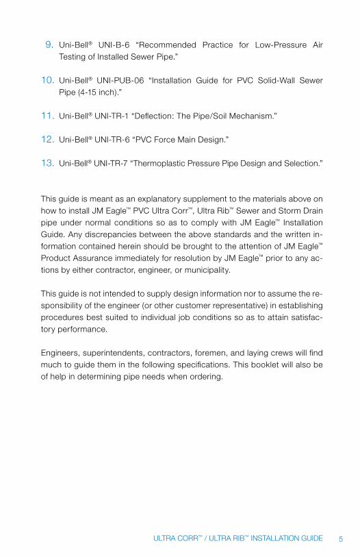
2.6 INSTALLATION Of ULTRA RIB™ & ULTRA CORR™ pIpE ThROUGh CASINGS
Casing Applications: most casing installations are made where pipe line must pass under airport runway, highways, railroad tracks and other loca-tions where conditions prevent the use of “open cut” excavation. where the situations are encountered, the engineer will specify boring or tunneling. with this type of excavation, it is generally preferable to insert a casing, usually of steel piping, through the obstruction by one of several methods.
2.6.1 pLACEmENT Of CASINGS
The placement of casings requires special equipment and skills. It is a spe-cialized field of construction, to which some construction firms devote their entire efforts. In the smaller diameters, the steel casing is usually placed progressively, fol-lowing the boring equipment as it tunnels through the obstruction. The rec-ommended practice is to use plain steel pipe (not corrugated) for the casing to facilitate movement of the pVC pipe through the casing with a minimum of resistance. for larger diameters, most casing construction is done by jack-ing the pipe from excavated pits. where long casings are involved, numerous pits for jacking operations are required along the route. Regardless of the diameter, accuracy in alignment and grade of the casing pipe is very important in maintaining the established inverts. proper grade of the inserted pipe is a must for satisfactory operation of a gravity flow line.
2.6.2 mINImUm CASING SIzES REQUIRED wITh ULTRA RIB™ AND ULTRA CORR™ pIpE
PVC Gravity Sewer Pipe: The following tables give the recommended size of casing required with various sizes of Ultra Rib™ and Ultra Corr™ sewer pipe.

19ULTRA CORR™ / ULTRA RIB™ INSTALLATION GUIDE
ULTrA rIb™ CASING SIZE
PIPE SIZE MINIMUM CASING SIZE
INCHES MM INCHES MM
8 200 12 400
10 250 16 450
12 300 18 500
15 375 20 600
18 450 24 650
21 525 30 750
24 600 30 850
Table 2
ULTrA COrr™ CASING SIZE
PIPE SIZE MINIMUM CASING SIZE
INCHES MM INCHES MM
24 600 30 889
27 675 36 975
30 750 42 1092
36 900 48 1270
Table 3
“B” Skid
Details 3”
1½”
3”
24” to 30”
“A” Skid
“E” dimention + 6”
1½” x 4”
Figure 5

20 ULTRA CORR™ / ULTRA RIB™ INSTALLATION GUIDE
2.6.3 pLACING pIpE ThROUGh CASINGS
The placing of pVC pipe through a steel casing entails several important considerations, often overlooked but necessary for a long-term, trouble-free installation. These are:
1. Ultra Rib™ and Ultra Corr™ pVC pipe inserted through a casing, should not rest on the bells. Therefore, the pipe lengths must be raised a sufficient distance to position the bells above the interior wall surface of the casing. Skids may be employed to properly raise, support and position the pipe lengths in the casing. Commercially available casing spacers may be employed as well.
2. The inserted pipeline should be circumferentially braced in the casing to prevent movement in any direction. for partially filled gravity lines, movement of the inserted pipe can be caused by flotation from flood-ing of the annular space between the casing and inserted pipe. Seal-ing the annular spaces at each end of the casing helps prevent flood-ing and the resulting flotation movement of the inserted pipeline.
2.6.4 SkIDS
Skids used on Ultra Rib™ or Ultra Corr™ pVC sewer pipe are inserted in a casing for three reasons:
1. To make the pull or push easier.2. To prevent the pipe and bells from snagging on the inside of the
casing during installation3. To keep the installed pipeline from resting on the bells.4. To keep pipe from over belling.
Skids should extend the full length of the pipe except the bells and spigot areas. They should also be high enough to allow for clearance between the bell and the casing bottom. minimum skid size is 2 inches by 4 inches. On the spigot end of Ultra Rib™ the skid size should end at the pipe assembly stop mark. This will help prevent overbelling during the pushing or pulling operation.

21ULTRA CORR™ / ULTRA RIB™ INSTALLATION GUIDE
Strapping
SkidsA Skid
Position brace
15”- 30”(375 mm - 750 mm)
6 skids and position braces
Wood cross piece
Skid
12” (350 mm)and under 4 skids and position braces
90˚
90˚
Figure 6
The leading or forward ends of the skids should be rounded as shown in “A” above. Notch the skids as shown for the strapping or wire to control the strapping operation and to prevent undue movement of the straps. fasten skids securely to the pipe with durable strapping. The spacing arrangement of the skids should be according to the diagram shown above.
Experience has shown that six skids and positioning braces are required on 15-inch to 36-inch Ultra Rib™ or Ultra Corr™, and four skids and positioning brac-es on 8-inch to 12-inch Ultra Rib™, to properly support the pipe and to prevent its lateral movement within the casing. The proper casing size is also important. See “Table of Casing Sizes” in Table 2 and 3 Skids and positioning braces should be identical in size since their service function is often interchange-able. however, adequate size is required to offset the difference between the bell O.D. and the spigot O.D. for 27-inch a true 2 inches and 4 inches will be required as a minimum. when pipe is pulled into a casing with a cable, the pipe may rotate, causing the skids and positioning braces to rotate from their entry position. Consequently, if the proper number, size and circumferential spacing of skids and braces are not employed, the bells cannot be kept from contacting the casing surfaces—and particularly the bottom of the casing.
2.6.5 CASING SpACERS
Commercially available casing spacers may be substituted for skids. Like skids, they should be positioned to support and restrain Ultra Rib™ or Ultra Corr™ in the casing to prevent the pipe from resting on the bells or floating.

22 ULTRA CORR™ / ULTRA RIB™ INSTALLATION GUIDE
45˚ 45˚
45˚ 45˚
Sizes 4” - 12”(51 mm - 300 mm)
Riser
Runners 45˚ 45˚
30˚ 30˚
15˚15˚
Sizes 15” - 36”(375 mm - 900 mm)
Figure 7
2.6.6 TypICAL CASING SpACER INSTALLATION
A minimum of two spacers per 14-foot length of Ultra Rib™ or Ultra Corr™ are required. There should be spaces on either side of the bell such that the maximum clear span between spacers does not exceed 7 feet. This recom-mendation is based on a maximum operating temperature of 73 degrees f (23 degrees C). If higher temperatures are anticipated, more spacers per joint may be required.
Lubrication reduces friction, makes pulling and pushing operation easier.
The application of a lubricant to the inside surface of the casing and/or the skids will make the sliding easier. The casing and/or skids can be lubricated with “Drilling mud” or “flaxsoap.” petroleum products, such as oil and grease, should not be used as lubricants since the prolonged ex-posure to these products is detrimental to the rubber rings used to seal the joints. To lubricate the casing, apply suitable lubricant at the end of the casing. Then attach rags to the cable and pull them through so that they act as swabs or spreaders. A rope attached to the cable will make it easy to retrieve the cable.

23ULTRA CORR™ / ULTRA RIB™ INSTALLATION GUIDE
Pulling Pipe through Casing
To pull the pipe, a cable is passed through the casing and the first pipe length. The cable end is fastened to a suitable crosspiece at the bell of the pipe as shown in figure 7 The cable is then pulled steadily (not jerked) by a truck winch, dozer or other method until about 2 feet of pipe is left projecting out of the casing. After the cable is passed through the next pipe, the two pipe sections are assembled and the pulling operation is repeated.
Angle Pull
CAUTION: If the cable is pulled at an angle, make sure that the leading pipe end is protected from damage.
Pushing Pipe through Casing
Ultra Rib™ or Ultra Corr™ pipe may also be pushed through the casing, using equipment which will exert a constant and uniform force against the pipe end. To accomplish this, the pushing equipment should be firmly anchored.
Closure at One End required
After the pipeline is through the casing, it will be necessary to make a clo-sure at one end to tie in to the pipeline already installed. where the pulling method is employed to insert the pipe, a space is left between the pipe already installed and the pipe bell end protruding out of the casing. A pipe section meeting the length requirement of the space between the bell of the pipe in the casing and the spigot end of the pipe in the trench (or vise-versa), plus one repair coupling, is used to make the closure. where the casing length is relatively short and the pushing method is used for placement of the pipe in the casing, the joing with the already-installed pipe can be easily accomplished by continuing the pushing operation, through the casing and into the prepared coupling of the installed pipe. when using this method of closure, the installed pipe should be laid to about 1 foot from the end of the casing. This way only a short section of the skids will have to be removed. In all cases, the skids and positioning braces around the pipe length should remain inside and near the end of the casing.

24 ULTRA CORR™ / ULTRA RIB™ INSTALLATION GUIDE
backfilling requirements
The need for backfilling the annular space in the casing under and around the pipe depends strictly on job specifications or local regulations applicable to the installation. wooden skids in backfill should have a long life. The life of the skids will be further extended if they are treated before backfilling. If there is no backfill, it is important that the skids are treated with a wood preserva-tive. functionally, it is not necessary to backfill around the pipe inside the casing with sand or other material when the proper skid arrangement has been employed. however, if groundwater is anticipated, the pipe must be kept from floating off grade.
Closed Casing Ends
If the ends of the casing are to be closed, the line should be tested for leak-age before closing the ends.
Method for backfilling Casing When required
where backfilling the annular space under and around the encased pipe is required, three-fourths of the distance to the top of the casing should be filled with sand or other approved backfill material. This will assist in prevent-ing movement of the encased pipe. Using a hose line, sand can be forced into the casing with water under pressure. Care must be taken to avoid forc-ing too much water into the casing because of the possibility of floating the pipe. flotation could result in uneven support for the encased pipeline if the skid system fails to prevent movement in all directions.
Pressure Grouting – Alternate Method for backfilling Casing
CAUTION: pressure grouting when not strictly controlled can collapse pVC pipe. pressure grouting is sometimes specified for filling in the annular space between the pipeline and the casing. If pressure grouting is to utilized, it will be necessary to arrange the skids/spacers and position braces on the pipe to accommodate a 2-inch grouting hose.
25ULTRA CORR™ / ULTRA RIB™ INSTALLATION GUIDE
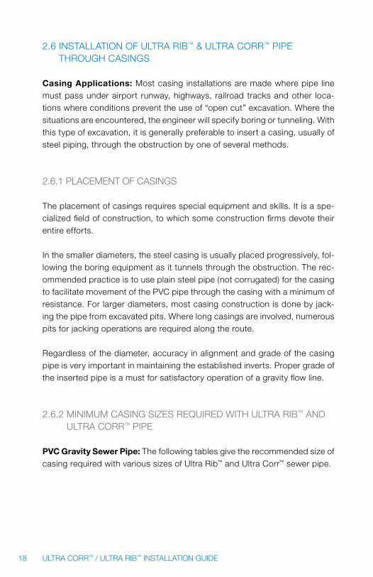
A suggested method for pressure grouting is:
1. Arrange the skids/spacers and position braces on the pipe as shown previously (figure 7) They will accommodate the grouting house.
2. Secure the grouting hose to the leading end of the first pipe section before insertion begins.
3. Either push or pull the pipe into the casing, channeling the hose in place on the leading end of each succeeding section of pipe.
4. Cap or plug each end of the bore, leaving an air hole at the top of the low end and a hole at the top of the high end for the grouting hose to pass through.
Using a grout mixture in a ratio of four parts cement to one part sand, with sufficient water to yield a consistency of thick soup.
Start pumping very slowly. A sensitive pressure gauge should be mounted on the discharge outlet of the grouting machine. A pressure will develop equal to the pressure needed to deliver the grout through the hose. After this pres-sure is established, any increase in pressure by 2 or 3 psi will indicate a need to pull the grouting hose slightly until the pressure returns to the established average delivery pressure. It is essential that the pressure generated does not exceed 2 or 3 psi over the initial required delivery pressure. Continue this procedure until the bore is completely grouted.
APPrOXIMATE bELL O.D OF ULTrA rIb™ PIPE
PIPE SIZE bELL O.D.
INCHES MM INCHES MM
8 200 9.76 247.90
10 250 12.22 310.39
12 300 14.60 370.84
15 375 17.50 444.50
18 450 21.40 543.56
21 525 25.50 647.70
24 600 28.50 723.90
27 675 32.50 825.50
Table 4

26 ULTRA CORR™ / ULTRA RIB™ INSTALLATION GUIDE
APPrOXIMATE bELL OF ULTrA COrr™ PIPE
PIPE SIZE APPrOXIMATE bELL O.D.
INCHES INCHES
24 30.00
27 34.00
30 37.80
36 45.80
Table 5
3.0 pipeline ConsTruCTion
3.1 INSpECTION
pipe and fittings should be inspected for defects or damage prior to lower-ing into the trench. Any defective, damaged or unsound pipe should be re-paired or replaced and all foreign matter or soil should be removed from the interior of the pipe and fittings, before lowering into the trench. If any ribs or corrugations are broken or missing from Ultra Rib™ or Ultra Corr™ pipe, See Section 1, “Receiving and handling pipe Shipments” for a determination of pipe serviceability.
3.2 LOwERING pIpE AND ACCESSORIES INTO TRENCh
All pipe, fittings, valves and accessories should be carefully lowered into the trench using suitable equipment in such a manner as to prevent damage to pipe and accessories. pIpE AND ACCESSORIES ShOULD NEVER BE DROppED OR DUmpED INTO ThE TRENCh.
DO NOT use chains or cables on Ultra Rib™ or Ultra Corr™ for lowering into the trench unless they are padded in some way to prevent damage to the pipe ribs. we recommend using nylon strap slings.
CAUTION: heavy impact may cause a slight longitudinal indentation in the outside of the pipe or break ribs and create a crack on the inside. This will result in a split as soon as the pipe is placed under loading. Any pipe that has been impacted should be examined closely for this type of damage.

27ULTRA CORR™ / ULTRA RIB™ INSTALLATION GUIDE
3.3 ASSEmBLy Of Jm EAGLE™ pVC ULTRA CORR™, ULTRA RIB™ pIpE
3.3.1 ULTRA RIB™ pIpE
make certain that both the bell and spigot are clean and have no foreign matter that could prevent an effective seal between the gasket and bell surfaces. Ultra Rib™ rings are shipped on the spigot to prevent loss of the ring. (See figure 9.)
Figure 8
IMPOrTANT: If for any reason the gasket must be placed on the pipe spigot in the field, the Ultra Rib™ ring should be placed between the second and third rib as shown in the figure 9. make sure the gasket is seated flatly in the groove so it is not twisted.
3.3.2 ULTRA CORR™ pIpE
make sure that both bell and spigot are clean and have no foreign matter that could prevent an effective seal between the gasket and bell surfaces. Ultra Corr™ rings are shipped on the spigot to prevent loss of the ring. IMPOrTANT: If for any reason the gasket must be placed on the pipe spigot in the field, the Ultra Corr™ ring should be placed between the first and second corrugation as shown in the figure 10. make sure the gasket is seated in the groove so it is not twisted.
Figure 9

28 ULTRA CORR™ / ULTRA RIB™ INSTALLATION GUIDE
CAUTION: If a joint is overassembled causing the spigot to jam into the neck of the bell, flexibility of the joint is lost. Uneven settlement of the trench may cause this type of assembly to leak. Do not assemble beyond the stop mark.
Overassembly must also be avoided because it will cause the spigot to squeeze down in the neck of the bell creating a reduced internal diameter of the spigot end. If deflection testing is conducted, the pipe may appear over deflected.
1. Do not lubricate the gasket because foreign material such as stones and dirt may adhere to the lubricated surface and become lodged between the gasket and the bell sealing surface. This could cause a leak in the joint.
2. Lubricate the inside of the bell. Be sure to cover the full circum-ference. Lubricant coating should be as thick as a fresh coat of enamel paint.
3. Lubricant can be applied with a brush, cloth pad, sponge or gloved hand.
4. Insert the spigot end into the bell so that the rubber ring is in con-tact with the bell end. The pipe can be allowed to sit in this position while the puller or come-along is attached for final assembly. It can also be assembled while the pipe is suspended from a backhoe or other equipment.
CAUTION: while attempting assembly, be sure the pipe lengths are in straight alignment and not deflected vertically or horizontally. Improper align-ment will cause a difficult or impossible assembly. If pipe must be deflected in line or grade, it can be done after assembly is completed. Such deflection should not exceed 1½ degrees at each joint. Also, note that deflection of an overassembled joint can cause leaks.
Small diameter Ultra Rib™ can be assembled by using the bar and block method. with the pipe properly supported, drive the steel bar into the trench bottom. Then place a wood stock at the end of the pipe and shove the pipe home. The wood block protects the pipe against damage by the bar. No mat-ter which method of assembly is used, be sure to push the spigot into the bell until the factory-applied stop mark on the pipe barrel is flush with the end of the bell. If assembling a field cut spigot, it will be necessary to first locate a reference “stop” mark as shown below.

29ULTRA CORR™ / ULTRA RIB™ INSTALLATION GUIDE
ULTRA RIB™ STOP MARK
Place Stop Mark
I D
Figure 10
ULTrA rIb™ STOP MArk
PIPE SIZESTOP MArk rIb LOCATION
INCHES MM
8 200 After 5th Rib from end of Spigot
10 250 After 6th Rib from end of Spigot
12 300 After 6th Rib from end of Spigot
15 375 After 5th Rib from end of Spigot
18 450 After 6th Rib from end of Spigot
21 525 After 5th Rib from end of Spigot
24 600 After 7th Rib from end of Spigot
27 675 After 6th Rib from end of Spigot
Table 6
ULTrA COrr™ STOP MArk
PIPE SIZESTOP MArk LOCATION
INCHES MM
24 600 middle of 5th Valley
27 675 Top of 4th Corrugation
30 750 Top of 4th Corrugation
36 900 Top of 4th Corrugation
Table 7

30 ULTRA CORR™ / ULTRA RIB™ INSTALLATION GUIDE
1. mark the field cut section with a pencil, crayon, tape or marking pen.2. Do not assemble pipe beyond the reference mark. By doing so, there
may not be enough clearance in the bell for possible expansion of the pipe due to temperature changes.
3. If pipe is accidentally assembled beyond the stop mark, it should be pried out flush with this mark before the next pipe is installed.
4. Bear in mind that in cold weather, assembly by bar and block is more difficult since the lower temperature causes the rubber ring to be-come stiff. you may want to use one of the other methods of assem-bly when the temperature is low.
5. To assemble Ultra Rib™ or Ultra Corr™ use only the Jm Eagle™ approved lubricant supplied, based on normal conditions. Extra lubricant need-ed for adverse conditions must be ordered separately. Lubricant is supplied for fittings based on the number of spigot ends involved.
Only lubricant approved by Jm Eagle™ should be used in assembling Ultra Rib™ or Ultra Corr™ pipe.
3.3.3 LUBRICANT REQUIREmENTS
The following table gives the number of pipe joints that can be assembled using a one quart container of lubricant for Ultra Rib™ or Ultra Corr™ pipe.
PIPE SIZENUMbEr OF JOINTS
INCHES MM
8 200 30
10 250 20
12 300 15
15 375 12
18 450 10
21 525 9
24 600 8
27 675 7
30 750 6
36 900 5
Table 8

31ULTRA CORR™ / ULTRA RIB™ INSTALLATION GUIDE
3.4 fIELD CUTTING Of ULTRA RIB™ OR ULTRA CORR™
It is easier and safer to cut pipe to the exact length before it is placed in the trench. A hand saw, with “cross cut” teeth is recommended for cutting Ultra Rib™ or Ultra Corr™. Because of the unique design of Ultra Rib™ and Ultra Corr™, it is possible to get exact cuts between the ribs or corruga-tions. Simply measure the required length from the pipe end and cut at the mid-point between the ribs as shown below.
NOTE: If an abrasive saw is used to cut Ultra Rib™ or Ultra Corr™ pipe, safety goggles should be worn by the saw operator to protect eyes from pipe chips.
Field cut here
ULTRA CORR™
Field cut here
ULTRA RIB™
Typical cutting location for Ultra Rib and Ultra Corr™ ™
Figure 11
NOTE: It is vital to remove mold flashing from the area where new rings are to be installed on Ultra Rib™ pipe in order to assure a tight seal.
Figure 12

32 ULTRA CORR™ / ULTRA RIB™ INSTALLATION GUIDE
3.5 UNDERwATER pIpE ASSEmBLy
1. Normally, the spigot end of the pipe is inserted into the bell during assembly. The spigot should be thoroughly double lubricated above the water surface before assembly. After the initial lubrication, wait for a period of four to five minutes before the second lubrication. The pipe should be assembled immediately after the second lubrication.
2. Cover on top of the pipe should be a minimum of three pipe diam-eters. Backfill material should be the same as described in Section 4.2, “Backfilling and Tamping.” Care should be taken to ensure no dirt gets into the joint before or during assembly.
3.6 fIELD TAppING
3.6.1 fIELD TAppING fOR ULTRA RIB™
The standard smooth I.D. saddle is approved for use with Ultra Rib™ and Ultra Corr™ pipe. Equivalent saddles produced by others are acceptable. Although photos below show Ultra Rib™ pipe, similar gaskets are available for Ultra Corr™.
1. Typical equipment required to make a saddle tap Ultra Rib™.
2. Use the saddle gasket as a template to mark the location of the hole to be cut.
3. hole can be cut using a hand saw or a sabre saw.
4. properly cut hole for saddle wye. (Note: hole for tee saddle will be round)

33ULTRA CORR™ / ULTRA RIB™ INSTALLATION GUIDE
5. Saddle gasket and silicone. 6. Apply silicone liberally around the grooved side of the gasket.
7. Apply silicone to the O.D. of Ultra Rib™
around the tap hole as shown.
8. properly applied silicone.
9. place saddle gasket over the tap hole as shown.
10. Apply silicone in a continuous bead as shown to the smooth side of the gasket.
11. properly align saddle with saddle gasket to prevent obstruction of incoming flow.
12. Attach two stainless steel bands as shown.
NOTE: when air testing, wait one hour between saddle assembly and testing to allow silicone to dry.

34 ULTRA CORR™ / ULTRA RIB™ INSTALLATION GUIDE
3.6.2 fIELD TAppING fOR ULTRA CORR™
1. Typical equipment required to make a saddle tap in Ultra Corr™ .
2. place saddle gasket over the tap hole as shown.
3. properly align saddle with saddle gasket to prevent obstruction of incoming flow.
NOTE: when air testing, wait one hour between saddle assembly and testing to allow silicone to dry.
3.7 mANhOLES AND RIGID STRUCTURES
Sewer systems require various sizes and types of manholes for two reasons:
1. To provide access to sewer lines for inspection and maintenance. 2. To provide for changes in sewer direction and elevation.
By design practice, sewer mains are usually constructed in straight lines be-tween manholes, which are located at points where directional changes are required. Drop manholes are used to provide for significant changes in grade or elevation due to the topography of the area. In addition, manholes are generally placed at intervals of 300 to 400 feet in sewer collecting lines. This distance varies with localities, engineers and sanitary engineering standards. The use of curved sewers, particularly in some west coast areas, has made it possible to reduce the number of manholes required on some projects.

35ULTRA CORR™ / ULTRA RIB™ INSTALLATION GUIDE
Type of manhole construction varies by locality with brick, concrete blocks, pre-cast concrete manhole sections, and fiberglas units being used. In more populated areas, pre-cast concrete manhole sections are now preferred be-cause of their superior strength, water tightness and economical installation features. Concrete does not bond to pVC pipe. This means that some form of seal or water stop is required if there is to be a watertight connection be-tween Ultra Rib™ or Ultra Corr™ and concrete structure.
3.7.1 CONNECTIONS TO mANhOLES AND OThER RIGID STRUCTURES
There are several accepted methods of connecting Ultra Rib™ to manholes and other rigid structures depending upon the style specified. Grouted Man-hole Connections: The gasket installed on the spigot end of Ultra Rib™ or Ultra Corr™ pipe will serve as a waterstop. The pipe may be grouted into the wall of the structure as shown in figure 14. The ribs or corrugations serve as a structural tie-in. Another method is to use a smooth manhole adaptor with a solid exterior covered by sand. By applying pVC solvent cement primer to the smooth end the pVC is softened such that the sand will adhere to it. The grout will then bond to the sand.
ULTRA CORR™
Manhole wall
ULTRA RIB™
Grout only Ultra Rib™ or Ultra Corr™ manhole entry
Grout
Manhole wall
Grout
Figure 13

36 ULTRA CORR™ / ULTRA RIB™ INSTALLATION GUIDE
booted Manhole Connections: The preferred method for making flexible boot connections with Ultra Rib™ is to utilize “flip Top” manhole adaptor gas-kets as shown below. A similar type flexible boot is available for Ultra Corr™— the “flat Top” manhole adaptor.
ULTrA rIb™ "FLIP TOP" MANHOLE ADAPTOr
1. Remove the Ultra Rib™ gasket from the pipe.
2. flip the manhole adaptor gasket inside out so that the flat side of the gasket is to the inside.
3. Slightly lubricate this flat side of the gasket and slide onto the pipe.
4. Continue sliding the gasket down the pipe barrel until the desired is reached.
5. At the desired location, flip the gasket so the flat surface is up.
6. make sure the "knobs" of the bottom side of the gasket are securely in place and between the ribs on the pipe.

37ULTRA CORR™ / ULTRA RIB™ INSTALLATION GUIDE
7. The pipe and gasket are ready for assembly into the manhole boot.
8. position the pipe and gasket inside the manhole boot so that gasket is under the strap location.
9. Tighten strap around the manhole boot with torque wrench or screwdriver. (torque to 60 inch/pounds).
10. Completed assembly.
ULTrA COrr™ "FLAT-TOP" MANHOLE ADAPTOr
1. follow same instructions for Ultra Corr™
as for Ultra Rib™

38 ULTRA CORR™ / ULTRA RIB™ INSTALLATION GUIDE
The approximate outside diameter of the “flip-Top” manhole gasket after installation on the pipe is shown in the table below.
The approximate outside diameter of the “flip-Top” manhole gasket after installation on the pipe is shown in the table on the next page.
PIPE SIZEULTrA rIb™
MANHOLE ADAPTOr GASkET O.D.
ULTrA COrr™ MANHOLE ADAPTOr
GASkET O.D.
INCHES MM INCHES MM INCHES MM
8 200 9.33 236.98 — —
10 250 11.55 292.10 — —
12 300 13.65 346.71 — —
15 375 16.67 423.42 — —
18 450 20.05 509.27 — —
21 525 23.51 597.15 — —
24 600 26.35 669.29 25.58 649.7
27 675 29.77 756.16 28.88 733.4
30 750 — — 32.15 816.6
36 900 — — 38.74 984.0
Table 9
Smooth Manhole Adaptors – Ultra Rib™: Another method of making booted manhole connections to Ultra Rib™ is to use the “Smooth” manhole adaptors as shown below.
Manhole wall Boot
Ultra Rib™ “Smooth” Manhole Adaptor Figure 14

39ULTRA CORR™ / ULTRA RIB™ INSTALLATION GUIDE
The “Smooth” manhole adaptor has the same spigot outside diameter di-mensions as pVC sewer pipe meeting ASTm D3034 or f679 with Ultra Rib™ bells. This is true for diameters 8 inches through 27 inches. for 30 inches, the spigot O.D. is that of cast iron 32 inches or pS46 (31.496 inches).
A-LOk Manhole Connections – Ultra rib™: where manholes are manu-factured with A-LOkS use the “Smooth” manhole adaptor shown below.
Figure 15
The A-LOk should be sized for D3034 or f679 for diameters 8 inches through 27 inches. for 30 inches it should be sized for 30 inches cast iron outside diameter 32 inches or for SDR35/pS46 31.50 inches. for 30-inch diameter, the actual dimension should be verified at the time of purchase.
Smooth Manhole Adaptors – Ultra Corr™: where manholes are manufac-tured with A-LOkS use the “Smooth” manhole adaptor as shown below.
Figure 16
where manholes are manufactured with A-LOks, use an Ultra Corr™ A-LOk entry piece.

40 ULTRA CORR™ / ULTRA RIB™ INSTALLATION GUIDE
The A-LOk should be sized as follows:
PIPE DIAMETEr ADAPTOr
INCHES INCHES
24 26.13
27 30.14
30 32.86
36 39.51
Table 10
3.7.2 pREpARATION Of mANhOLE fOR fUTURE CONNECTIONS
Sewer projects quite often include manholes from which sewer lines will be connected and installed at some future date. This situation frequently occurs in suburban developments where housing units are constructed in stages over a period of time. where such future sewer extensions are planned, pro-visions should be made in the manholes to facilitate these connections.
3.7.3 CONNECTIONS TO DROp mANhOLES
Drop manholes are used to provide for significant changes in grade or eleva-tion resulting from the topography of the area. These structures should be used as infrequently as possible since they are a source of high turbulence in sewage flow. The wpCf manual of practice, No. 9, Chapter 6, states that where hydrogen sulfide gas is present in sewage, agitation and turbulence developed by drop manholes can cause the release of this gas into the sewer atmosphere, resulting in severe odor problems or, under certain conditions, lethal, odorless concentration of the gas injurious to human health and in-strumental to corrosion of the manhole structures. Two types of drop manholes are currently being designed for use with pVC plastic pipe.
1. Inside-drop manholes2. Outside-drop manholes

41ULTRA CORR™ / ULTRA RIB™ INSTALLATION GUIDE
The inside-drop manhole has become the preferred method in many areas because of its economic and maintenance benefits.
The outside-drop manhole is the old standard that has been used for many years.
please refer to the “Uni-Bell® handbook of pVC pipe Design and Construc-tion” for further details.
3.7.4 SEwER ChImNEyS OR RISERS, RIGID STRUCTURES REQUIRING SpECIAL TREATmENT
Sewer design engineers and contractors should be aware of the design and construction requirements associated with vertical sewer chimneys and deep angular risers. Considerable loads are transferred by frictional forces of the backfill Additional loads are transferred by the backfill above and surface loads to and through the chimneys or risers to the sewer pipe and fittings below. All of these loads are in turn transmitted in the form of concentrated weight to the supporting trench bedding beneath the structures. This extra, concentrated loading requires special treatment to provide adequate support for both pipe and fittings in sewer chimneys or riser installations. for further details refer to the “Uni-Bell® handbook of pVC pipe Design and Construction.”
for angular risers and lateral house connections, care should be taken when installing lateral piping to avoid excessive settlement from poor com-paction which can cause broken or leaky fittings and pipe joints. Efforts should be made to place lateral pipes on well-compacted or undisturbed soil whenever possible.
4.0 pipe embedmenT
Understanding flexible conduit terminology is essential for the installer. The soil class and density realized in the bedding, hunching, and initial backfill, as well as the manner and care with which they are placed, are important factors in achieving a satisfactory installation of a flexible conduit. Over-de-flection, when it occurs, is invariably the result of improper compaction in

42 ULTRA CORR™ / ULTRA RIB™ INSTALLATION GUIDE
the hunching area. Below is an illustration of a typical trench with all major regions identified, as they will be addressed in the following sections.
Pipezone
6 in - 12 in
EmbedmentMaterial
Initialbackfill
Haunching
Bedding max. 6 in
Foundation(may not be required)
Springlineof pipe
Figure 17
4.1 fOUNDATION
A foundation is required when the trench bottom is unstable. Any foundation that will support a rigid pipe without causing loss of grade or flexural break-ing will be more than adequate for pVC pipes.
4.2 BEDDING
Bedding is required primarily to bring the trench bottom up to grade. Bed-ding materials should be placed to provide uniform longitudinal support un-der the pipe to prevent low spots. Blocking should not be used to bring the pipe to grade. Bell holes at every joint will allow for the joint to be assembled properly and maintain adequate support. Under normal circumstances, a bedding of 4 inches to 6 inches compacted is of sufficient thickness for the bedding. If the native trench soil is comprised of fine grain soils and migration of those soils into the bedding material is anticipated, either wide trench con-struction, a well-graded bedding material without voids, or a fabric barrier should be used to avoid compromising the trench backfill materials.

43ULTRA CORR™ / ULTRA RIB™ INSTALLATION GUIDE
4.3 BACkfILLING AND TAmpING
Backfilling should follow pipe assembly as closely as possible. This pro-tects the pipe from falling rocks, eliminates possibility of lifting the pipe from grade due to flooding of an open trench, avoids shifting pipe out of line by cave-ins, and in cold weather lessens the possibility of backfill mate-rial becoming frozen.
4.3.1 hAUNChING AND INITIAL BACkfILL The haunching area is the most important in terms of limiting the deflection of a flexible pipe. This is the area that should be compacted to the required or specified density.
Initial backfill begins above the springline of the pipe to a level 6 inches to 12 inches above the top of the pipe. Compacting soils to levels above the springline gives little additional side support.
There are two basic purposes of the haunching and initial backfilling of a flexible conduit such as Ultra Rib™ or Ultra Corr™ pipe:
1. To provide the soil side support, which is necessary to enable the pipe and the soil to work together to meet the designed load require-ments within the allowable deflection limits.
2. To provide protection for the pipe from impact damage due to large rocks, etc. contained in the final backfill.
The essentials of satisfactory haunching and initial backfilling can be summarized as follows:
1. provide approved materials, properly compacted continuously above the bedding and around the pipe to the spring-line, as well as between the pipe and undisturbed trench walls.
2. provide a cushion of approved materials from 6 inches to 12 inches over the pipe and between the trench walls in accordance with the engineer’s specifications.

44 ULTRA CORR™ / ULTRA RIB™ INSTALLATION GUIDE
After the bedding material has been placed according to Section 4.1, place the haunching and initial backfill by hand to a 1-foot minimum depth of cover above the pipe to give pipe support and cushion. In doing so, proper control should be exercised to avoid vertical and horizontal displacement of the pipe from proper alignment. This backfill should be a selected material, free from rocks greater than 1.5 inches in diameter, dirt clods or frozen material. This material is solely responsible for providing effective support of the pipe in the haunching area and limiting deflection. This is accomplished by tamping the embedment materials under the haunches and around the pipe to the spring-line of the pipe. Side support is accomplished by tamping the soil firmly under the haunches of the pipe out to the trench walls. Tamping should be done in 4-inch layers to the height specified by the engineer, but in no case less than to the sprin-gline of the pipe. when the specified height is reached, the tamping can be stopped. If automatic tampers are used, care should be exercised to avoid damaging the pipe. for more information on tamping, see Section 4.4.1.
A. Right—Backfill correctly placed by hand filling all voids.
B. Wrong—Backfill not placed evenly.
Figure 18
The immediate placement of initial backfill will provide adequate weight of soil on the pipe so that expansion and contraction will be evenly distributed over each pipe length. This portion of the backfill begins at the spring-line of the pipe and extends to some predetermined distance above the pipe. Since little to no side support is derived from the soils placed in this area, native soils maybe used without tremendous compaction efforts, unless in the influence zone of other structures. It should be noted that at shallow

45ULTRA CORR™ / ULTRA RIB™ INSTALLATION GUIDE
depths of cover (less than 3 feet) flexible conduits may deflect and rebound under dynamic loading if the trench width is not highly compacted, resulting in damage to road surfaces. for pipes buried under flexible road surfaces at depths less than 3 feet, it is recommended that a minimum of 90 percent proctor density be achieved from the bottom of the trench up to the road sur-face using Class I or Class II materials as described in Appendix 1. minimum cover is recommended to be 1 foot from the top of rigid road surfaces or the bottom of flexible road surfaces.
4.4 COmpLETING ThE BACkfILL
The trench should be carefully inspected before final backfilling to detect and remove any loose stones, which may have fallen into the trench.
The material that completes the backfilling operation need not be as carefully selected as the initial material, unless specified by the engineer. Care should be taken, however, to avoid including large stones in the backfill. They might damage the pipe when dropped or forced through the soil cushion of the initial backfill against the pipe.
The consolidation of the final backfill above the initial backfill material has no effect, except for weight, on flexible pipe performance. Therefore, its place-ment and compaction should be completed in consideration of other factors such as paving. however, nothing should be done above the pipe zone that will alter the previously compacted backfill in the pipe zone. 4.4.1 fINAL BACkfILL
The final backfill should be placed and spread in uniform layers in such a manner as to completely fill the trench with a uniformly dense backfill load on the pipe and avoid unfilled spaces in the backfill. Rolling equipment should not be used until a minimum of 18 inches of backfill material has been placed over the top of the pipe. If a hydro hammer is to be used to compact the backfill, a minimum of 3 feet of cover is required. Unless otherwise speci-fied, trenches under pavements, sidewalks, or roads should be backfilled and compacted to 90 percent density, as determined by the American As-sociation of highway and Transportation Officials method T99 for State

46 ULTRA CORR™ / ULTRA RIB™ INSTALLATION GUIDE
Compaction and Density of Soils. Unless specified, other trenches may be backfilled without controlled compaction in the final backfill. Additional back-fill material should be supplied, if needed, to completely backfill the trenches or to fill depressions caused by subsequent settlement.
for description of backfill materials and their recommended usage, please refer to Appendix 1.
4.5 COmpACTION mEThODS
The first step in providing effective support for the pipe in the haunching area is to tamp the embedment materials under the haunches and around the pipe to the spring-line of the pipe.
Tamping should be done with hand tamping bars, mechanical tampers, or by using water to consolidate the embedment materials. with hand tamping, satisfactory results can be accomplished in damp, loamy soils and sands. for more cohesive soils, the necessary compaction may require the use of mechanical tampers. water tamping should be limited to trenches excavated in soils in which water drains through quickly and, in so doing, compacts the embedment material.
4.5.1 TAmpING BARS
Two types of tamping bars should be available for a good tamping job. The first should be a bar with a narrow head. (See A or B of figure 20.) These are used to tamp under the pipe. The second tamping bar should have a flat head. It is used to compact the soil along the sides of the pipe to the trench walls. (See figure 20 C.)
Tamping bars of the type shown in “A” and “B” are used for tamping under pipe and joints. The flat tamper “C” is used at the sides, between pipe and trench walls.

47ULTRA CORR™ / ULTRA RIB™ INSTALLATION GUIDE
1” bar
weld to flat bar6” x 4” x 1
60”
¾” - 1“ or 1¼” pipe
30° bend
A B C
30°bend
tee and two4” nipples
Figure 19
Do not attempt to use the flat tamper (C) in place of A or B. It will not work properly.
4.5.2 mEChANICAL TAmpERS
Care should be taken to avoid contact between the pipe and compaction equipment. Compaction of the embedment material should generally be done in such a way that the compaction equipment is not used directly above the pipe until sufficient backfill has been placed to ensure that the use of compac-tion equipment will not damage the pipe or cause deflection of the pipe. when hydro-hammers are used to achieve compaction, they should not be used within 3 feet of the top of the pipe and then, only if the embedment material density has been previously compacted to a minimum 85 percent proctor density. 4.5.3 fLOOD OR wATER TAmpING
flooding or water tamping should be used only in trenches that are excavat-ed in soils from which water drains quickly and, at the same time, compacts the haunching material.

48 ULTRA CORR™ / ULTRA RIB™ INSTALLATION GUIDE
If flooding is used, the approved embedment material is first hand placed, making certain all voids under, around and along both sides of the pipe and couplings are filled. Initial embedment material should be placed to a height sufficient to prevent floating of the pipe.
CAUTION: Be careful not to float the pipe.
4.5.4 wATER-JETTING
The introduction of water under pressure to the embedment material is not to be used to compact the embedment material of pVC pipe, or any other flexible conduit.
4.5.5 ShEETING AND TRENCh BOXES
when sheeting is used, it should be left in place unless it is designed to prevent disturbing the soil adjacent to the pipe when pulled and removed. If heavy wood-en sheeting has to be pulled, well-graded granular material should be placed on each side of the pipe for a distance of at least two pipe diameters. The granular material should be compacted to at least 90 percent Standard proctor Density. whenever possible, sheeting and bracing should be installed so that the bot-tom of the sheeting extends no lower than the spring-line of the pipe. when installed in this manner, pulling the sheeting will not disturb the embedment material providing sidewall support for the pipe. If a trench box is used, it should be designed so that the backend of the sides do not extend below the pipe spring-line. This will allow filling and compaction of the annular space as the trench box is moved forward.
4.6 SpECIAL CONDITIONS AND CONSIDERATIONS
4.6.1 fROzEN BACkfILL
1. most soils have a tendency to adhere when frozen, becoming large lumps which can produce excessive impact on the pipe during the backfilling operation.
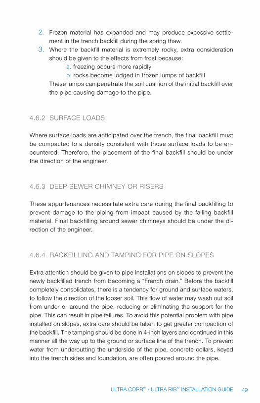
49ULTRA CORR™ / ULTRA RIB™ INSTALLATION GUIDE
2. frozen material has expanded and may produce excessive settle-ment in the trench backfill during the spring thaw.
3. where the backfill material is extremely rocky, extra consideration should be given to the effects from frost because:
a. freezing occurs more rapidlyb. rocks become lodged in frozen lumps of backfill
These lumps can penetrate the soil cushion of the initial backfill over the pipe causing damage to the pipe.
4.6.2 SURfACE LOADS
where surface loads are anticipated over the trench, the final backfill must be compacted to a density consistent with those surface loads to be en-countered. Therefore, the placement of the final backfill should be under the direction of the engineer.
4.6.3 DEEp SEwER ChImNEy OR RISERS
These appurtenances necessitate extra care during the final backfilling to prevent damage to the piping from impact caused by the falling backfill material. final backfilling around sewer chimneys should be under the di-rection of the engineer.
4.6.4 BACkfILLING AND TAmpING fOR pIpE ON SLOpES
Extra attention should be given to pipe installations on slopes to prevent the newly backfilled trench from becoming a “french drain.” Before the backfill completely consolidates, there is a tendency for ground and surface waters, to follow the direction of the looser soil. This flow of water may wash out soil from under or around the pipe, reducing or eliminating the support for the pipe. This can result in pipe failures. To avoid this potential problem with pipe installed on slopes, extra care should be taken to get greater compaction of the backfill. The tamping should be done in 4-inch layers and continued in this manner all the way up to the ground or surface line of the trench. To prevent water from undercutting the underside of the pipe, concrete collars, keyed into the trench sides and foundation, are often poured around the pipe.

50 ULTRA CORR™ / ULTRA RIB™ INSTALLATION GUIDE
4.6.5 SUppORT Of ABOVE GROUND pIpE
The installation of Ultra Rib™ pipe above ground requires continuous sup-port except at the joints where the support should be removed to allow clearance for the pipe bells. pipe above ground should be protected from sunlight and vandalism.
5.0 pipe TesTinG and repair
5.1 DEfLECTION
Deflection is the reduction of the vertical diameter of a flexible pipe due to an imposed load.
Figure 20
The amount of deflection that will occur after installation is a function of:
1. pipe stiffness (f y)2. Soil stiffness (density) in the pipe zone.3. Load imposed on the pipe.
Of the above three factors, the most important influence on limiting deflection is soil stiffness (density) in the pipe zone, especially in the haunching area. See Section 4.0, “pipe Embedment” for the trench cross-section terminology.
Test data plotted for deflection as a function of load and soil density clearly show that deflection is controlled primarily by soil density in the pipe zone and not by soil class. The following chart illustrates the maximum limits of deflection that can be expected in different soil classes when compacted to the densities shown. Remember, the density referred to is the “haunching” area of the pipe zone.

51ULTRA CORR™ / ULTRA RIB™ INSTALLATION GUIDE
5.2 pIpE DEfLECTION
Deflection testing is not required when using proper construction practices and inspection during pipe installation and when using embedment material which has been properly selected, placed, and compacted. however, it may be required that random deflection tests of pipe be performed before final acceptance at construction locations between successive manholes where the construction encountered unstable trench walls or bottoms, heavy rain-fall, frozen soil, high ground water levels, deep lines, or difficulty in attaining compaction. Locations with excessive deflection should be repaired by re-bedding or replacement of the pipe. Deflection testing is usually performed with properly sized "go, no-go" mandrel or sewer ball. for the purpose of deflection measurements the base inside pipe diameters without deflection are provided in Table 11. The maximum allowable deflection should be sub-tracted from these base inside diameters in determining the maximum diam-eter of the "go, no-go" test mandrel or ball. It must be emphasized that to insure accurate testing, the lines must be thoroughly cleaned.
5.2.1 DEfLECTION TESTING
It is the position of Jm Eagle™ manufacturing that deflection testing of pVC pipe is unnecessary when pipe is installed in accordance with the accept-able practices stated in this guide. most towns and municipalities limit initial deflection to 5 percent, when in actuality ASTm D3034 recommends pVC pipe deflection at 7.5 percent of base inside diameter. Thus, exceeding these limits does not necessarily indicate any structural damage, failure or reduc-tion in life and only add to the cost of the project. proof of this position is that more than 750 million feet of pVC sewer pipe are performing satisfactorily in the field today. On the other hand, where improper installation practices are known or suspected, questionable bedding materials are employed, and/or installation conditions are severe, deflection testing of these sections of the installation should be considered advisable by the engineer.

52 ULTRA CORR™ / ULTRA RIB™ INSTALLATION GUIDE
bASE INSIDE DIAMETErS 7.5 % DEFLECTION MANDrEL DIMENSIONS
NOMINAL PIPE SIZE (IN)
bASE INSIDE DIAMETEr
(IN)
O.D. OF 7.5% DEFLECTION MANDrEL
(IN)
4 3.86 3.57
6 5.72 5.29
8 7.63 7.06
10 9.52 8.81
12 11.31 10.46
15 13.82 12.79
18 16.92 15.65
21 19.95 18.46
24 22.60 20.90
27 25.44 23.54
30 28.35 26.22
33 31.24 28.91
36 34.10 31.55
39 37.00 34.23
42 39.88 36.89
45 42.76 39.56
48 45.63 42.22
Table 11
5.3 mAkING LEAkAGE TESTS
After the Ultra Rib™ or Ultra Corr™ sewer pipe has been laid and backfilled, each section of the pipeline between manholes should be tested by a low-pressure air test or a water infiltration test. There are some obvious advantages to the air test method such as:
1. A test method which provides accurate results 2. Time saving, especially in large diameters 3. A clean test4. An inexpensive test compared with water exfiltration testing. (water
can be costly, particularly on large diameter jobs.)

53ULTRA CORR™ / ULTRA RIB™ INSTALLATION GUIDE
PIP
E S
TIF
FN
ES
S —
F/y
- 4
6 P
SI
AS
TM
b
ED
DIN
G
CL
AS
SIF
ICA
TIO
N
DE
NS
ITY
(P
rO
CT
Or
) A
AS
HT
O
T-9
9
HE
IGH
T O
F C
OV
Er
(F
EE
T)
(ME
TE
rS
)
(ft.
)3
58
1012
1416
182
02
22
42
62
83
03
23
43
6
(m.)
.91
1.5
22
.44
3.0
53
.66
4.2
74
.88
5.4
96
.10
6.7
17.
32
7.9
38
.54
9.15
9.76
10.3
710
.98
Gra
vel
Cla
ss I
Cla
ss II
90
%
max
imum
7.5
% d
eflec
tion
T
his
zone
not
rec
om
men
ded
80
%
San
dC
lass
III
90
%
85% 75
%
65%
Cla
yC
lass
IV
85% 75
%
65%
pea
tC
lass
V
Thi
s so
il cl
ass
not
reco
mm
end
ed.
Tab
le 1
2
1. N
o le
ngth
of p
ipe
inst
alle
d u
nder
co
nditi
ons
sp
ecifi
ed w
ill d
eflec
t m
ore
tha
n is
ind
icat
ed;
th
e p
ipe
will
defl
ect
less
tha
n th
e am
oun
t
ind
icat
ed if
sp
ecifi
ed d
ensi
ty is
ob
tain
ed.
2. E
xter
nal l
oad
ing
bas
ed u
po
n so
il w
eig
ht a
t
120
lbs.
per
cub
ic fo
ot.
No
te:
Ultr
a R
ib™
has
bee
n b
urie
d u
p t
o 50
' d
eep.
fo
r b
uria
l cha
rt in
fo a
t th
ose
dep
ths
cons
ult
your
m
anuf
actu
rer'
s re
pre
sent
ativ
e.
3. D
eflec
tions
pro
dic
ted
are
bas
ed u
po
n p
ipe
whi
ch
was
initi
ally
circ
ular
prio
r to
inst
alla
tion.
Act
ual
defl
ectio
ns m
ay d
iffer
bec
ause
of i
nitia
l out
of
roun
dne
ss c
ause
d b
y st
ora
ge
and
/or
ha
ndlin
g. T
hese
var
iatio
ns s
houl
d b
e ta
ken
in
to a
cco
unt
whe
n m
easu
ring
defl
ectio
ns a
re
com
par
ed w
ith t
hose
in t
he t
able
.
4. B
edd
ing
clas
sific
atio
ns a
re a
s in
dic
ated
on
pag
e 15
an
d c
orr
esp
ond
to
AS
Tm
D23
21.
5. D
eflec
tions
list
ed in
tab
le a
re m
axim
um
long
-ter
m v
alue
s. T
he s
ugg
este
d m
axim
um lo
ng-
term
val
ue is
7.5
per
cent
whi
ch is
ap
pro
xim
etal
y eq
ual t
o a
5 p
erce
nt in
itial
defl
ectio
n.
6. In
itial
defl
ectio
n is
defl
ectio
n ta
ken
with
in t
he 1
st 2
4 ho
urs
afte
r tr
ench
is b
ackfi
lled
.
No
te:
Defl
ectio
n va
lues
sho
wn
do
not
incl
ude
effe
ct o
f liv
e lo
ad o
r lo
ngitu
dia
l ben
din
g.

54 ULTRA CORR™ / ULTRA RIB™ INSTALLATION GUIDE
when performing an air test, ASTm f1417-92 (1998) “Test method for Installation Acceptance of plastic Gravity Sewer Lines Using Low-pressure Air” must be adopted for safety and consistency. however, the engineer reserves the right to choose the type of test (air or water) to be conducted. A comparison of the two test methods is very complex. Results can vary greatly depending both on the type of leak involved and the type of backfill material surrounding the pipe. for example, light clay soil versus clean sand. Because of the complexity of equaling the test results, these tests cannot be claimed to be strict equivalents. Both test specifications are meaningful. All caps and end plugs should be blocked by a stake or other means prior to air testing. This will prevent dislodging of the end cap or plug and prevent failure of the air test.
5.3.1 AIR TESTING
when the air test is specified, the engineer should give explicit instructions for conducting the test in accordance with ASTm f1417 practices, including times for a 0.5 psig pressure drop. Should any test on any section of the pipeline disclose an air loss rate greater than permitted, the contractor shall, at his own expense, locate and repair the defective joints or pipe sections. After the repairs are completed, the line shall be retested until the air loss rate is within the specified allowance.
WArNING: when air is compressed in pVC pipe, it poses a severe explo-sion hazard and may result in pipe failure and/or injury to property and/or persons. Don’t use pVC for compressed air systems. Do not exceed 9 psig of air pressure.
5.3.2 INfILTRATION TESTING (wATER)
when high ground water tables exist and the infiltration test is required, the engineer shall give explicit instructions for conducting the test. The maxi-mum allowable amount of infiltration rate measured by the test shall be 28 gallons per inch of pipe diameter per mile per 24 hours.

55ULTRA CORR™ / ULTRA RIB™ INSTALLATION GUIDE
Should any test on any section of the pipeline disclose an infiltration rate greater than permitted, the contractor shall, at this own expense, locate and repair the defective joints or pipe sections. After the repairs are completed, the line shall be retested until the infiltration is within the specified allowance.
5.3.3 EXfILTRATION TESTING (wATER) when an exfiltration test is required, the engineer should give explicit instruc-tions to be followed in carrying out the test. The maximum allowable exfiltra-tion rate measured by the test shall be 28 gallons per inch of diameter per mile per 24 hours. The average internal pressure of the system under test shall not be greater than 5 psi (11.6-foot head), and the maximum internal pressure in any part of the system under test shall not be greater than 10.8 psi (25-foot head).
Should any test on any section of the pipeline disclose and exfiltration rate greater than permitted, the contractor shall, at his own expense, locate and repair the defective joints or pipe sections. After the repairs are completed, the line shall be retested until the exfiltration is within the specified allowance.
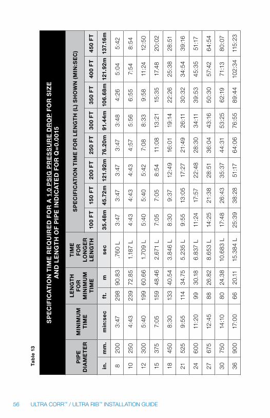
56 ULTRA CORR™ / ULTRA RIB™ INSTALLATION GUIDE
SP
EC
IFIC
AT
ION
TIM
E r
Eq
UIr
ED
FO
r A
1.0
PS
IG P
rE
SS
Ur
E D
rO
P F
Or
SIZ
E
AN
D L
EN
GT
H O
F P
IPE
IN
DIC
AT
ED
FO
r q
=0.
001
5
PIP
E
DIA
ME
TE
rM
INIM
UM
T
IME
LE
NG
TH
F
Or
M
INIM
UM
T
IME
TIM
E
FO
r
LO
NG
Er
L
EN
GT
H
SP
EC
IFIC
AT
ION
TIM
E F
Or
LE
NG
TH
(L
) S
HO
WN
(M
IN:S
EC
)
100
FT
150
FT
20
0 F
T2
50
FT
30
0 F
T3
50
FT
40
0 F
T4
50
FT
in.
mm
.m
in:s
ec
ft.
mse
c3
5.4
8m
45
.72
m12
1.9
2m
76.2
0m
91.4
4m
106
.68
m12
1.9
2m
137.
16m
820
03
:47
298
90.
83.7
60
L3
:47
3:4
73
:47
3:4
73
:48
4:26
5:0
45
:42
1025
04:
4323
972
.85
1.18
7 L
4:43
4:43
4:43
4:57
5:5
66
:55
7:54
8:5
4
1230
05
:40
199
60.
661.
709
L5
:40
5:4
05
:42
7:0
88
:33
9:5
811
:24
12:5
0
1537
57:
0515
948
.46
2.67
1 L
7:05
7:05
8:5
411
:08
13:2
115
:35
17.4
820
:02
1845
08
:30
133
40.5
43.
846
L8
:30
9:3
712
:49
16:0
119
:14
22:2
625
:38
28:5
1
2152
59
:55
114
34.7
55.
235
L9
:55
13:0
517
:27
21:4
926
:11
30:3
234
:54
39:1
6
246
00
11:2
099
30.1
86.
837
L11
:24
17:5
722
:48
28:3
034
:11
39:5
345
:35
51:1
7
2767
512
:45
8826
.82
8.65
3 L
14:2
521
:38
28:5
136
:04
43:1
650
:30
57:4
264
:54
3075
014
:10
80
24.3
810
.683
L17
:48
26:4
335
:37
44:3
153
:25
62:1
971
:13
80
:07
369
00
17:0
066
20.1
115
.384
L25
:39
38:2
851
:17
64:0
676
:55
89:4
410
2:34
115
:23
Tab
le 1
3

57ULTRA CORR™ / ULTRA RIB™ INSTALLATION GUIDE
SP
EC
IFIC
AT
ION
TIM
E r
Eq
UIr
ED
FO
r A
0.5
PS
IG P
rE
SS
Ur
E D
rO
P F
Or
SIZ
E
AN
D L
EN
GT
H O
F P
IPE
IN
DIC
AT
ED
FO
r q
=0.
001
5
PIP
E
DIA
ME
TE
rM
INIM
UM
T
IME
LE
NG
TH
F
Or
M
INIM
UM
T
IME
TIM
E
FO
r
LO
NG
Er
L
EN
GT
H
SP
EC
IFIC
AT
ION
TIM
E F
Or
LE
NG
TH
(L
) S
HO
WN
(M
IN:S
EC
)
100
FT
150
FT
20
0 F
T2
50
FT
30
0 F
T3
50
FT
40
0 F
T4
50
FT
in.
mm
.m
in:s
ec
ft.
mse
c3
5.4
8m
45
.72
m12
1.9
2m
76.2
0m
91.4
4m
106
.68
m12
1.9
2m
137.
16m
820
03
:47
298
90.
83.7
60
L3
:47
3:4
73
:47
3:4
73
:48
4:26
5:0
45
:42
1025
04:
4323
972
.85
1.18
7 L
4:43
4:43
4:43
4:57
5:5
66
:55
7:54
8:5
4
1230
05
:40
199
60.
661.
709
L5
:40
5:4
05
:42
7:0
88
:33
9:5
811
:24
12:5
0
1537
57:
0515
948
.46
2.67
1 L
7:05
7:05
8:5
411
:08
13:2
115
:35
17.4
820
:02
1845
08
:30
133
40.5
43.
846
L8
:30
9:3
712
:49
16:0
119
:14
22:2
625
:38
28:5
1
2152
59
:55
114
34.7
55.
235
L9
:55
13:0
517
:27
21:4
926
:11
30:3
234
:54
39:1
6
246
00
11:2
099
30.1
86.
837
L11
:24
17:5
722
:48
28:3
034
:11
39:5
345
:35
51:1
7
2767
512
:45
8826
.82
8.65
3 L
14:2
521
:38
28:5
136
:04
43:1
650
:30
57:4
264
:54
3075
014
:10
80
24.3
810
.683
L17
:48
26:4
335
:37
44:3
153
:25
62:1
971
:13
80
:07
369
00
17:0
066
20.1
115
.384
L25
:39
38:2
851
:17
64:0
676
:55
89:4
410
2:34
115
:23
Tab
le 1
4

58 ULTRA CORR™ / ULTRA RIB™ INSTALLATION GUIDE
5.4 mAkING REpAIRS AND TIE-INS
If Ultra Rib™ or Ultra Corr™ is damaged at the job site and it becomes nec-essary to replace a full length of Ultra Rib™ or Ultra Corr™, you will need the following materials:
1 – 3-foot-3-inch bell x spigot quarter length1 – 6-foot-6-inch spigot x spigot half length1 – 3-inch-3-inch spigot x spigot quarter length2 – Ultra Rib™ or Ultra Corr™ repair couplings6 – Gaskets
first, cut out and remove the damaged length of pipe, being careful not to disturb the adjacent pipe’s bell or spigot. Then install the repair pieces in the following manner:
1. Install the quarter lengths and position the half length for installation after loosely placing the repair couplings on the pipe. (figure 21)
Repair coupling
Figure 21
2. move the half length into line and grade and position the couplings for final tightening. (figure 22)
Repair coupling - see detail below
Typical for Ultra Rib™ and Ultra Corr™
Typical cutting location for Ultra Rib and Ultra Corr™ ™
Figure 22

59ULTRA CORR™ / ULTRA RIB™ INSTALLATION GUIDE
6.0 dimensions and weiGHTs
ULTrA rIb™ DIMENSIONS
NOMINAL PIPE SIZE
(IN)
MIN. I.D. (IN)
APPrOX. O.D. (IN)
APPrOX. bELL O.D.
(IN)
MIN. T. (IN)
APPrOX. PIPE WEIGHT (LBS/100 FT)
8 7.863 8.81 10.20 0.060 250
10 9.825 11.02 12.80 0.070 350
12 11.687 13.10 15.26 0.085 490
15 14.303 15.91 18.04 0.105 730
18 17.510 19.32 22.02 0.130 1050
21 20.656 21.73 26.17 0.160 1450
24 23.412 25.48 28.91 0.180 2120
27 26.371 28.50 32.85 0.205 2470
Table 15
I D
Waterway Minimum Wall (t)
O.D.BARREL
(t)
O.D.BELL
Figure 23

60 ULTRA CORR™ / ULTRA RIB™ INSTALLATION GUIDE
ULTrA COrr™ DIMENSIONS
NOMINAL PIPE SIZE (IN)
MIN. I.D. (IN)
APPrOX. O.D.
bArrEL (IN)
MIN. WALL THICkNESS
APPrOX. WEIGHT (LBS/FT)
APPrOX. bELL O.D. (IN)
Inner Wall
t1 (IN)
Outer Wall
t2 (IN)
At Valley
t3 (IN)
24 23.412 25.58 0.110 0.085 0.123 18.2 28.7
27 26.371 28.86 0.120 0.091 0.137 20.2 32.5
30 29.388 32.15 0.130 0.105 0.147 26.0 35.8
36 35.370 38.74 0.150 0.125 0.171 36.1 43.4
Table 16
O.D.BELL
O.D.BARREL
Waterway Minimum Wall (t)
(t)
O.D.BELL
O.D.BARREL
Waterway Minimum Wall (t)
(t)
Figure 24

61ULTRA CORR™ / ULTRA RIB™ INSTALLATION GUIDE
NOTICE TO ALL rEADErS OF THIS GUIDE: pVC pipe installation may be hazardous to pipe, property, and/or persons if this guide and/or the recommendations of Jm Eagle™ manufacturing are not adhered to fully. Jm Eagle™ has made every effort to expose all known dangers of misus-ing pVC pipe in this guide; however, Jm Eagle™ cannot possibly know or anticipate all situations or outcomes. Jm Eagle™ maintains the position that pVC pipe is the most reliable and safest piping material available. Thus, Jm Eagle™ encourages all users of our products to exercise good judg-ment when installing our products and to consult Jm Eagle™ for additional information when questions or concepts illustrated herein are not fully an-swered or understood. It is recommended that all users of our products (or persons handling) attend training on pipe construction, installation, and safety prior to working with our products to ensure safety, knowledge, and understanding. Should you need further assistance, please contact Jm Eagle™ product Assurance at 1-800-621-4404.

62 ULTRA CORR™ / ULTRA RIB™ INSTALLATION GUIDE
appendix 1
EmBEDmENT mATERIALS
materials suitable for foundation and embedment are classified in the fol-lowing Table A1.1. They include a number of processed materials plus soil types defined according to the Unified Soil Classification System (USCS) in ASTm D2487, “Standard method for Classification of Soils for Engineering purposes.” Table A1.2 provides recommendations on the installation and use based on class of soil or aggregates and location within the trench. It is im-portant to engineer all materials used in the pipe trench to work together and with the native material surrounding the trench.
Class IA Materials: Class IA materials provide the maximum stability and pipe support for a given density because of the angular interlocking of the material particles. with minimum efforts, these materials can be installed at relatively high densities over a wide range of moisture contents. These mate-rials also have excellent drainage characteristics that may aid in the control of water. These soils are often desirable as embedment in rock cuts where water is frequently encountered. On the other hand, when ground water flow is anticipated, consideration should be given to potential migration of fines from adjacent materials into the open graded Class IA materials.
Class Ib Materials: Class IB materials are produced by mixing Class IA and natural or processed sands to produce a particle-size distribution that minimizes migration from surrounding soils that may contain fines. They are more widely graded than Class IA and thus require more compaction effort to achieve the minimum density specified. when these materials are properly compacted these soils exhibit high stiffness and strength, and depending on the amount of fines, may be relatively free draining.
Class II Materials: when Class II materials are compacted, they provide a relatively high level of pipe support. In most respects, they all have the desirable characteristics of Class IB materials when widely graded. how-ever, open-graded groups may allow for migration and the sizes should be checked for compatibility with the native trench materials. Typically, Class II materials consist of rounded particles and are less stable than the angular materials of Class IA and IB unless they are confined and compacted.

63ULTRA CORR™ / ULTRA RIB™ INSTALLATION GUIDE
Class III Materials: These materials provide less support for a given den-sity than Class I or Class II materials. high levels of compaction effort are required if moisture content is not controlled. These materials will provide reasonable support once proper compaction is achieved.
Class IV-A Materials: Class IV-A materials must be carefully evaluated before use. The moisture content of the materials must be near optimum to minimize compaction effort and achieve the required density. properly placed and compacted, these soils can provide reasonable levels of pipe support. however, these materials may not be suitable under high fills, sur-face applied dynamic loads, or under heavy vibratory compactors and tam-pers. These materials should be avoided if water conditions in the trench may cause instability and result in uncontrolled water content.

64 ULTRA CORR™ / ULTRA RIB™ INSTALLATION GUIDE
T
ab
le A
1.1
De
scri
pti
on
of
Ma
teri
al C
lass
ific
ati
on
as
De
fin
ed
in A
ST
M D
232
1
Pe
rce
nta
ge
Pa
ssin
g
Sie
ve S
ize
sA
tte
rbe
rg
Lim
its
Co
effi
cie
nts
Cla
ssTy
pe
So
il S
ymb
ol
Gro
up
De
scri
pti
on
AS
TM
D24
871.
5 in
(4
0 m
m)
No
.4
(4.7
5 m
m)
No
.20
0
(.07
5 m
m)
LL
PL
Un
ifo
rmit
y C
uC
urv
atu
re
Cc
IA
man
ufac
ture
d A
ggre
gate
s:
open
gra
ded
, cl
ean
Non
e
Ang
ular
, cru
shed
sto
ne o
r
rock
, cru
shed
sla
g, c
ind
ers
or
she
ll: la
rge
void
con
tent
, co
ntai
n lit
tle o
r no
fine
s
100
%<
or
= 1
0%
< 5
%N
on
pla
stic
IB
man
ufac
ture
d,
pro
cess
ed
Agg
rega
tes:
d
ense
gra
ded
, cl
ean
Non
e
Ang
ular
, cru
shed
sto
ne
(or
othe
r C
lass
IA m
ater
ials
) an
d st
one/
sand
mix
ture
s w
ith
grad
atio
ns s
elec
ted
to m
inim
ize
mig
ratio
n of
ad
jace
nt s
oils
: co
ntai
n lit
tle to
no
fines
100
%<
or
= 5
0%
< 5
%N
on
pla
stic
IIC
oar
se-G
rain
ed
So
ils:
clea
nG
ww
ell-
gra
ded
gra
vels
and
g
rave
l-sa
nd m
ixtu
res:
litt
le t
o no
fine
s10
0%
< 5
0%
of
coar
se
frac
tion
< 5
%N
on
pla
stic
> 4
1 to
3
Gp
po
orly
-gra
ded
gra
vels
an
d g
rave
l-sa
nd m
ixtu
res:
lit
tle t
o no
fine
s<
4<
1 o
r >
3
Sw
wel
l-g
rad
ed s
and
s an
d g
rav-
elly
san
ds:
litt
le t
o no
fine
s
< 5
0%
of
coar
se
frac
tion
> 6
1 to
3
Sp
po
orly
-gra
ded
san
ds
and
g
rave
lly s
and
s: li
ttle
to
no fi
nes
< 6
< 1
or
> 3
Co
arse
-Gra
ined
S
oils
: b
ord
erlin
e cl
ean
to w
/fine
s
San
ds
and
gra
vels
whi
ch
are
bo
rdel
ine
bet
wee
n
clea
n an
d w
ith fi
nes
100
%va
ries
5% t
o 12
%N
on
pla
stic
Sam
e as
fo
r G
w, G
p,
Sw
, and
Sp
Bas
ed o
n ta
ble
s fo
und
in t
he U
ni-B
ell®
pV
C p
ipe
Ass
ocia
tion,
“h
and
boo
k of
pV
C p
ipe
Des
ign
and
Con
stru
ctio
n”.

65ULTRA CORR™ / ULTRA RIB™ INSTALLATION GUIDE
T
ab
le A
1.1
co
nti
nu
ed
Pe
rce
nta
ge
Pa
ssin
g
Sie
ve S
ize
sA
tte
rbe
rg L
imit
sC
oe
ffic
ien
ts
Cla
ssTy
pe
So
il S
ymb
ol
Gro
up
De
scri
pti
on
AS
TM
D24
871.
5 in
(4
0 m
m)
No
.4
(4.7
5 m
m)
No
.20
0
(.07
5 m
m)
LL
PL
Un
ifo
rmit
y C
uC
urv
atu
re
Cc
IIIC
oar
se-G
rain
ed
So
ils w
/ fi
nes
Gm
Silt
y g
rave
ls,
g
rave
l-sa
nd-s
ilt m
ixtu
res
100
%>
50
% o
f co
arse
fr
actio
n
> 1
2% t
o
< 5
0%
< 4
or
<
”A”
Lin
e
GC
Cla
yey
gra
vels
,
gra
vel-
sand
-cla
y m
ixtu
res
< 7
a n
d
> ”
A” L
ine
Sm
Silt
y sa
nds,
sa
nd-s
ilt m
ixtu
res
> 5
0%
of
coar
se
frac
tion
> 4
or
<
”A”
Lin
e
SC
Cla
yey
sand
s,
sand
-silt
mix
ture
s>
7 a
nd
> “
A” L
ine
IV-A
fine
-Gra
ined
S
oils
: In
org
anic
mL
Ino
rgan
ic s
ilts
and
ver
y fin
e sa
nds,
ro
ck fl
our
, si
lty o
r cl
ayey
fine
san
ds,
silt
s
with
slig
ht p
last
icity
100
%10
0%
> 5
0%
< 5
0<
4 o
r
< “
A” L
ine
CL
Ino
rgan
ic c
lays
of l
ow t
o
med
ium
pla
stic
ity,
gra
vely
cl
ays,
san
dy
clay
s, s
ilty
clay
s, le
an c
lays
> 7
and
>
“A”
Lin
e
Bas
ed o
n ta
ble
s fo
und
in t
he U
ni-B
ell®
pV
C p
ipe
Ass
ocia
tion,
“h
and
boo
k of
pV
C p
ipe
Des
ign
and
Con
stru
ctio
n”.

66 ULTRA CORR™ / ULTRA RIB™ INSTALLATION GUIDE
T
ab
le A
1.2 re
com
men
dat
ion
s fo
r in
sta
llati
on
an
d u
se o
f s
oils
an
d a
gg
reg
ates
fo
r F
ou
nd
atio
n, e
mb
ed
men
t, a
nd
bac
kfil
l
So
il C
lass
as
De
fin
ed
in T
ab
le A
1.1
Cla
ss I
AC
lass
Ib
Cla
ss I
IC
lass
III
Cla
ss I
V-A
Gen
eral
R
ecom
men
dat
ions
an
d R
estr
ictio
ns
Do
not
use
whe
re c
ond
-tio
ns m
ay c
ause
mig
ratio
n of
fine
s fr
om a
dja
cent
soi
l an
d lo
ss o
f pip
e su
pp
ort.
Sui
tab
le fo
r us
e as
a d
rain
-ag
e b
lank
et a
nd u
nder
dra
in
in r
ock
cuts
whe
re a
dja
cent
m
ater
ial i
s su
itab
ly g
rad
ed.
pro
cess
mat
eria
ls
as r
equi
red
to o
btai
n gr
adat
ion
whi
ch w
ill
min
imiz
e m
igra
tion
of
adja
cent
mat
eria
ls.
Sui
tab
le fo
r us
e as
d
rain
age
bla
nket
and
un
der
dra
in.
whe
re h
ydra
ulic
gr
adie
nt e
xist
s ch
eck
grad
atio
n to
min
imiz
e m
igra
tion.
“C
lean
” gr
oup
s su
itab
le fo
r us
e as
dra
inag
e b
lan-
ket
and
und
erd
rain
.
Do
not
use
whe
re w
ater
co
nditi
ons
in t
renc
h m
ay
caus
e in
stab
ility
Obt
ain
geot
echn
ical
eva
lu-
atio
n of
pro
cess
ed m
ater
ial.
may
not
be
suita
ble
und
er
high
ear
th fi
lls, s
urfa
ce a
p-
plie
d lo
ads
and
und
er h
eavy
vi
bra
tory
com
pac
tors
and
ta
mp
ers.
Do
not
use
whe
re
wat
er c
ond
ition
s in
tre
nch
may
cau
se in
stab
ility
.
foun
dat
ion
Sui
tab
le a
s fo
und
atio
n an
d fo
r re
pla
cing
ove
r-ex
ca-
vate
d an
d un
stab
le t
renc
h b
otto
m a
s re
stric
ted
abov
e.
Inst
all a
nd c
omp
act
in 6
in
ch m
axim
um la
yers
.
Sui
tab
le a
s fo
und
a-tio
n an
d fo
r re
pla
c-in
g ov
er-e
xcav
ated
an
d un
stab
le t
renc
h b
otto
m. I
nsta
ll an
d co
mp
act
in 6
inch
m
axim
um la
yers
.
Sui
tab
le a
s fo
und
atio
n an
d fo
r re
pla
cing
ov
er-e
xcav
ated
and
un
stab
le t
renc
h b
otto
m a
s re
stric
ted
abov
e. In
stal
l and
co
mp
act
in 6
inch
m
axim
um la
yers
.
Sui
tab
le a
s fo
und
atio
n an
d fo
r re
pla
cing
ove
r-ex
cava
ted
tren
ch b
otto
m
as r
estr
icte
d ab
ove.
Do
not
use
in t
hick
ness
es
grea
ter
than
12
inch
es
tota
l. In
stal
l and
com
pac
t in
6 in
ch m
axim
um la
yers
.
Sui
tab
le o
nly
in u
ndis
turb
ed
cond
ition
and
whe
re t
renc
h is
dry
. Rem
ove
all l
oose
m
ater
ial a
nd p
rovi
de
firm
, un
iform
tre
nch
bot
tom
bef
ore
bed
din
g is
pla
ced.
Bas
ed o
n ta
ble
s fo
und
in t
he U
ni-B
ell®
pV
C p
ipe
Ass
ocia
tion,
“h
and
boo
k of
pV
C p
ipe
Des
ign
and
Con
stru
ctio
n”.

67ULTRA CORR™ / ULTRA RIB™ INSTALLATION GUIDE
T
ab
le A
1.2
co
nti
nu
ed
So
il C
lass
as
De
fin
ed
in T
ab
le A
1.1
Cla
ss I
AC
lass
Ib
Cla
ss I
IC
lass
III
Cla
ss I
V-A
Bed
din
g
Sui
tab
le a
s re
stric
ted
abov
e. In
stal
l in
6 in
ch m
axim
um la
yers
. Le
vel fi
nal g
rad
e b
y ha
nd.
min
imum
dep
th
4 in
ches
(6
inch
es in
ro
ck c
uts)
.
Inst
all a
nd c
om
pac
t in
6 in
ch m
axim
um
laye
rs.
Leve
l fina
l g
rad
e b
y ha
nd.
min
imum
dep
th 4
in
ches
(6
inch
es in
ro
ck c
uts)
.
Sui
tab
le a
s re
stric
ted
abov
e. I
nsta
ll an
d c
om
pac
t in
6 in
ch m
axim
um la
yers
.
Leve
l fina
l gra
de
by
hand
.
min
imum
dep
th 4
inch
es
(6 in
ches
in r
ock
cut
s).
Sui
tab
le o
nly
in d
ry t
renc
h co
nditi
ons
. In
stal
l and
co
mp
act
in 6
inch
max
i-m
um la
yers
. Le
vel fi
nal
gra
de
by
hand
. m
inim
um
dep
th 4
inch
es (
6 in
ches
in
ro
ck c
uts)
.
Sui
tab
le o
nly
in d
ry t
renc
h
cond
itio
ns a
nd w
hen
op
timum
p
lace
men
t an
d c
om
pac
tion
cont
rol i
s m
aint
aine
d.
Inst
all a
nd
com
pac
t in
6 in
ch m
axim
um
laye
rs.
Leve
l fina
l gra
de
by
hand
. m
inim
um d
epth
4 in
ches
(6
inch
es in
ro
ck c
uts)
.
hau
nchi
ng
Sui
tab
le a
s re
stric
ted
abov
e. In
stal
l in
6 in
ch m
axim
um la
yers
. w
ork
in a
roun
d p
ipe
by
hand
to
pro
vid
e un
iform
sup
po
rt.
Inst
all a
nd c
om
pac
t in
6 in
ch m
axim
um
laye
rs.
wo
rk in
ar
oun
d p
ipe
by
hand
to
pro
vid
e un
iform
su
pp
ort
.
Sui
tab
le a
s re
stric
ted
abov
e. In
stal
l and
co
mp
act
in 6
inch
m
axim
um la
yers
. w
ork
in
aro
und
pip
e b
y ha
nd t
o p
rovi
de
unifo
rm s
upp
ort
.
Sui
tab
le a
s re
stric
ted
abov
e. In
stal
l and
co
mp
act
in 6
inch
m
axim
um la
yers
. w
ork
in
aro
und
pip
e b
y ha
nd t
o p
rovi
de
unifo
rm s
upp
ort
.
Sui
tab
le o
nly
in d
ry t
renc
h
cond
itio
ns a
nd w
hen
op
timum
p
lace
men
t an
d c
om
pac
tion
cont
rol i
s m
aint
aine
d.
Inst
all a
nd
com
pac
t in
6 in
ch m
axim
um la
y-er
s. w
ork
in a
roun
d p
ipe
by
hand
to
pro
vid
e un
iform
sup
po
rt.
Initi
al B
ackfi
ll
Sui
tab
le a
s re
stric
ted
abov
e.
Inst
all t
o a
min
imum
of 6
inch
es
abov
e p
ipe
crow
n.
Inst
all a
nd c
om
pac
t to
a m
inim
um o
f 6
inch
es a
bov
e p
ipe
crow
n.
Sui
tab
le a
s re
stric
ted
abov
e. In
stal
l and
co
mp
act
to a
min
umum
of 6
inch
es
abov
e p
ipe
crow
n.
Sui
tab
le a
s re
stric
ted
abov
e.
Inst
all a
nd c
om
-p
act
to a
min
umum
of 6
in
ches
ab
ove
pip
e cr
own.
Sui
tab
le a
s re
stric
ted
ab
ove.
In-
stal
l and
co
mp
act
to a
min
umum
of
6 in
ches
ab
ove
pip
e cr
own.
fina
l Bac
kfill
Co
mp
act
as r
equi
red
by
the
eng
inee
r.C
om
pac
t as
req
uire
d b
y th
e en
gin
eer.
Co
mp
act
as r
equi
red
by
th
e en
gin
eer.
Co
mp
act
as r
equi
red
by
the
eng
inee
r.
Sui
tab
le a
s re
stric
ted
ab
ove.
C
om
pac
t as
req
uire
d b
y th
e en
gin
eer.
Bas
ed o
n ta
ble
s fo
und
in t
he U
ni-B
ell®
pV
C p
ipe
Ass
ocia
tion,
“h
and
boo
k of
pV
C p
ipe
Des
ign
and
Con
stru
ctio
n”.

NOTES:


Building essentials for a better tomorrow
revised January 2009JmE-04B
© J-m manufacturing Co., Inc.
5200 west Century BlvdLos Angeles, CA 90045T: 800.621.4404 f: 800.451.4170
Nine peach Tree hill RoadLivingston, NJ 07039 T: 973.535.1633 f: 973.533.4185
www.Jmeagle.com
Global HeadQuarTers: reGional oFFiCe: