UL listed CSA recognized • DIN-Sized (48 x 48mm) Housing...
49
TIMERS TIMERS 4 Products and specifications subject to change without notice. Consult factory for application assistance. 204 Airline Drive, Suite 300, Coppell, Texas 75019 / Tel: (800) 677-5311 / FAX: (800) 677-3865 / www.crouzet-usa.com 4-5 812 SERIES DELAY ON MAKE TIMER UL listed CSA recognized • DIN-Sized (48 x 48mm) Housing • Dual LCD Display Shows Setpoint and Actual • Up or Down Timing • DPDT Output Relay • Popular Octal Socket Relay The 812 Timer is a Delay on Make digital timer with a DPDT output relay in the industry standard octal socket plug-in base. The series has a large, easy to read LCD display that shows actual and preset time values as well as relay output relay output status. Easy programming from front panel allows selection of eleven time ranges from.01 sec. to 9999 hours. MODES OF OPERATION: Delay on Make TIMER 812 POW IN RUN 1 2 3 4 5 6 7 8 9 10 11 12 VALID MODE T Input Power S1 Relay R1 R2 WIRING: SPECIFICATIONS: Input Power . . . . . . . . . . . . . . . . 110 VAC, 220 VAC, . . . . . . . . . . . . . . . . . . . . . . . . 24 VAC/DC, +10%, -15% . . . . . . . . . . . . . . . . . . . . . . . . 50/60 Hz Input Power Consumption . . . . . 0.5 W at 24 V . . . . . . . . . . . . . . . . . . . . . . . . 3.5 VA at 110 V . . . . . . . . . . . . . . . . . . . . . . . . 11 VA at 230 V Display . . . . . . . . . . . . . . . . . . . . Timing Display .3˝ (7.5mm) . . . . . . . . . . . . . . . . . . . . . . . . High 4 Digit LCD . . . . . . . . . . . . . . . . . . . . . . . . Preset Display .18˝ (4.5mm) . . . . . . . . . . . . . . . . . . . . . . . . High 4 Digit LCD Output Output . . . . . . . . . . . . . . . . . . DPDT Output Rating . . . . . . . . . . . . . 5 Amp/250 VAC resistive load Maximum Power Rating . . . . . 1200 VA/120 W Min. Switch Current . . . . . . . . 100 mA Mechanical Life of Relay . . . . 5 x 10 6 Electrical Life of Relay . . . . . . 10 5 at max. rated load . . . . . . . . . . . . . . . . . . . . . . . . and at 10 cycles per minute max. Time Ranges . . . . . . . . . . . . . . . 99.99 s 999.9 s . . . . . . . . . . . . . . . . . . . . . . . . 9999 s 99 min 59 s . . . . . . . . . . . . . . . . . . . . . . . . 99.99 min 999.9 min . . . . . . . . . . . . . . . . . . . . . . . . 9999 min 99 h 59 min . . . . . . . . . . . . . . . . . . . . . . . . 99.99 hrs 999.9 hrs . . . . . . . . . . . . . . . . . . . . . . . . 9999 hrs Front Panel Rating . . . . . . . . . . . NEMA 12 Repeat Accuracy . . . . . . . . . . . . ±0.03%, ±20 ms Reset Time . . . . . . . . . . . . . . . . . 50 ms Insulation Resistance . . . . . . . . 100 MΩ min @ 500 VAC to IEC 255.5 Dielectric Strength . . . . . . . . . . . 2000 VAC @ 50 Hz for 1 min to VDE 0435 Operating Temperature . . . . . . . +14°F to +140°F (-10°C to 60°C) Storage Temperature . . . . . . . . . -22°F to 150°F (-30°C to 70°C) Weight . . . . . . . . . . . . . . . . . . . . 140 grams Dimensions . . . . . . . . . . . . . . . . 48 x 48 x 85mm Panel Cutout . . . . . . . . . . . . . . . 45 x 45mm (+0.6 ) ORDERING INFORMATION: V olta g e P ar t Number 24 VAC/DC 88 857 409 110 VAC 88 857 406 220 VAC 88 857 400 When input power (S1) is applied, the timer delay begins. DPDT relay energizes after the timing period. Interruption of input power resets timer. Timer is supplied with relay status indicator on LCD display. 1 2 3 4 5 6 7 8 PROGRAMMING: 1: Power On Indicator 2: Timing Indicator 3: Timing Display 4: Timing Range Unit 5: Decimal Point 6: Up or Down Timing 7: Timing Range 8: Relay Output Status 9: Program Mode 10: Validation 11: Preset Keyboard 12: Preset Value Display DIMENSIONS See page 4-2
Transcript of UL listed CSA recognized • DIN-Sized (48 x 48mm) Housing...

TIMERS TIMERS
4
Products and specifications subject to change without notice.Consult factory for application assistance.
204 Airline Drive, Suite 300, Coppell, Texas 75019 / Tel: (800) 677-5311 / FAX: (800) 677-3865 / www.crouzet-usa.com4-5
812 SERIESDELAY ON MAKE TIMERUL listed CSA recognized
• DIN-Sized (48 x 48mm) Housing
• Dual LCD Display Shows Setpoint and Actual
• Up or Down Timing
• DPDT Output Relay
• Popular Octal Socket Relay
The 812 Timer is a Delay on Make digital timer with a DPDT output relayin the industry standard octal socket plug-in base. The series has a large,easy to read LCD display that shows actual and preset time values aswell as relay output relay output status. Easy programming from frontpanel allows selection of eleven time ranges from.01 sec. to 9999 hours.
MODES OF OPERATION:
Delay on Make
TIMER 812POW IN RUN
1 2
3 4
5
6
7
8
910 11
12VALID MODE
R
T
Input Power S1
RelayR1 R2
WIRING:
SPECIFICATIONS:Input Power . . . . . . . . . . . . . . . . 110 VAC, 220 VAC,
. . . . . . . . . . . . . . . . . . . . . . . . 24 VAC/DC, +10%, -15% . . . . . . . . . . . . . . . . . . . . . . . . 50/60 Hz
Input Power Consumption . . . . . 0.5 W at 24 V . . . . . . . . . . . . . . . . . . . . . . . . 3.5 VA at 110 V . . . . . . . . . . . . . . . . . . . . . . . . 11 VA at 230 V
Display . . . . . . . . . . . . . . . . . . . . Timing Display .3˝ (7.5mm) . . . . . . . . . . . . . . . . . . . . . . . . High 4 Digit LCD . . . . . . . . . . . . . . . . . . . . . . . . Preset Display .18˝ (4.5mm) . . . . . . . . . . . . . . . . . . . . . . . . High 4 Digit LCD
OutputOutput . . . . . . . . . . . . . . . . . . DPDTOutput Rating . . . . . . . . . . . . . 5 Amp/250 VAC resistive loadMaximum Power Rating . . . . . 1200 VA/120 WMin. Switch Current . . . . . . . . 100 mAMechanical Life of Relay . . . . 5 x 10⁶
Electrical Life of Relay . . . . . . 105 at max. rated load . . . . . . . . . . . . . . . . . . . . . . . . and at 10 cycles per minute max.
Time Ranges . . . . . . . . . . . . . . . 99.99 s 999.9 s . . . . . . . . . . . . . . . . . . . . . . . . 9999 s 99 min 59 s . . . . . . . . . . . . . . . . . . . . . . . . 99.99 min 999.9 min . . . . . . . . . . . . . . . . . . . . . . . . 9999 min 99 h 59 min . . . . . . . . . . . . . . . . . . . . . . . . 99.99 hrs 999.9 hrs . . . . . . . . . . . . . . . . . . . . . . . . 9999 hrs
Front Panel Rating . . . . . . . . . . . NEMA 12Repeat Accuracy . . . . . . . . . . . . ±0.03%, ±20 msReset Time . . . . . . . . . . . . . . . . . 50 msInsulation Resistance . . . . . . . . 100 MΩ min @ 500 VAC to IEC 255.5Dielectric Strength . . . . . . . . . . . 2000 VAC @ 50 Hz for 1 min to VDE 0435Operating Temperature . . . . . . . +14°F to +140°F (-10°C to 60°C)Storage Temperature . . . . . . . . . -22°F to 150°F (-30°C to 70°C)Weight . . . . . . . . . . . . . . . . . . . . 140 gramsDimensions . . . . . . . . . . . . . . . . 48 x 48 x 85mmPanel Cutout . . . . . . . . . . . . . . . 45 x 45mm (+0.6)
ORDERING INFORMATION:Voltage Part Number24 VAC/DC 88 857 409110 VAC 88 857 406220 VAC 88 857 400
When input power (S1) is applied, the timer delay begins.DPDT relay energizes after the timing period. Interruption ofinput power resets timer. Timer is supplied with relay status indicator on LCD display.
1
2
3
4 5
6
7
8
PROGRAMMING:
1: Power On Indicator2: Timing Indicator3: Timing Display4: Timing Range Unit5: Decimal Point6: Up or Down Timing7: Timing Range8: Relay Output Status9: Program Mode10: Validation 11: Preset Keyboard12: Preset Value Display
DIMENSIONS See page 4-2

814 SERIESMULTIFUNCTION TIMERUL listed CSA recognized
• DIN-Sized (48 x 48mm) Housing
• 6 Modes of Operation
• Large LCD Display
• Up or Down Timing
• SPDT 10 Amp Relay Output
• NEMA 12 Front Panel
The 814 Series Timer is a multifunction timer with multi-time ranges(0.01 sec to 9999 hours) housed in a 1/16 DIN (48 x 48mm) style enclo-sure. Easy programming from the front panel push buttons allows selec-tion of up or down timing, 6 different timing functions (Delay on Make,Delay on Break, Interval, Single Shot, Repeat Cycle ON Time First andRepeat OFF Time First) and 11 different timing ranges. A large 4-digitLCD display indicates current and preset values as well as relay output,power input, and initiate switch status. Load such, as light bulb or con-tactor can be connected to the start switch. Slide switch on side of unitprovides lockout of front panel access to operating mode programming.
SPECIFICATIONS:Input Power . . . . . . . . . . . . . . . . 220 VAC, 115 VAC, 48 VAC/DC, 24 VAC/DC
12 VDC, 50/60 Hz, ±15% Input Power Consumption . . . . 11 VA at 220 VAC 0.5 W at 24 VDC
. . . . . . . . . . . . . . . . . . . . . . . . 4 VA at 110 VAC 0.5 W at 12 VDC . . . . . . . . . . . . . . . . . . . . . . . . 1 VA at 24 VAC
Display . . . . . . . . . . . . . . . . . . . Timing Display .3˝ (7.5mm) High 4 Digit LCD . . . . . . . . . . . . . . . . . . . . . . . . Preset Display .18˝ (4.5mm) High 4 Digit LCD
Initiate Switch Input . . . . . . . . . Dry Contact (50 ms min.)Output
Output . . . . . . . . . . . . . . . . . . . SPDT Relay Max. Switching Current/Voltage . 8 pin Version: 10 Amp 250 VAC . . . . . . . . . . . . . . . . . . . . . . . . . . . . 11 pin Version: 8 Amp 250 VACMax. Power Rating . . . . . . . . . . . . 2000 VA/50 WMin. Switch Current . . . . . . . . . . . 100 mAElectrical Life of Relay . . . . . . . . . 2 x 10⁵ Operations
Time Ranges . . . . . . . . . . . . . . . . . . 99.99 s, 999.9 s . . . . . . . . . . . . . . . . . . . . . . . . . . . . 9999 s, 99 min, 59 s . . . . . . . . . . . . . . . . . . . . . . . . . . . . 99.99 min 999.9 min . . . . . . . . . . . . . . . . . . . . . . . . . . . . 9999 min 99h 59 min . . . . . . . . . . . . . . . . . . . . . . . . . . . . 99.99 hrs 999.9 hrs . . . . . . . . . . . . . . . . . . . . . . . . . . . . 9999 h . . . . . . . . . . . . . . . . . . . . . . . . . . . . Note: The 99.99 s time range is not available
in the Repeat Cycle ModeFront Panel Rating . . . . . . . . . . . . . NEMA 12Repeat Accuracy . . . . . . . . . . . . . . . +0.03%Reset Time . . . . . . . . . . . . . . . . . . . . 50 ms during timing
. . . . . . . . . . . . . . . . . . . . . . . . . . . . 50 ms after timingInsulation Resistance . . . . . . . . . . . 100 MΩ min @ 500 VAC to IEC 255.5Dielectric Strength . . . . . . . . . . . . . 2000 VAC @ 50 Hz for 1 min to VDE 0435Operating Temperature . . . . . . . . . . +14°F to +140°F (-10°C to +60°C)Weight . . . . . . . . . . . . . . . . . . . . . . . . 3.5 oz. (100g)Panel Cutout . . . . . . . . . . . . . . . . . . 45 x 45mm ( )
ORDERING INFORMATION:
MODE OF OPERATIONS:
+0.60
WIRING:
1: Power On Indicator2: Initiate Switch Indicator3: Timing Indicator4: Timing Display5: Timing Range Unit6: Decimal Point7: Mode of Operation8: Up or Down Timing9: Timing Range
10: Relay Output Status11: Program Mode12: Validation13: Preset Keyboard14: Preset Value Display
PROGRAMMING:
VOLTAGE220/110 VAC/24 VAC/DC48/24 VAC/DC/12 VDC
8 PIN VERSION88 857 00588 857 003
11 PIN VERSION88 857 10588 857 103
VOLTAGEVOLTAGE
PART NUMBER8 PIN
PART NUMBER11 PIN
PWR
INI
RST
RLYT ONT OFF T OFF T ON t
PWR
INI
RST
RLYT OFFT ON T ON T OFF t
TIMER 814IN
14
10
4
1 2 6 3
5
~+
*
S1
S2Start
4 56
781
2
3
~–
~+
*
S1
S2Start
6
8
910
112
3
4
~–
1
75
PWR
INI
RST
RLYT ON
PWR
INI
RST
RLYT ON8 8
PWR
INI
RST
RLY
8 T OFF
PWR
INI
RST
RLYT ON88 8 8 8
For 24 VAC/VDC service voltage for 8 pin versions jumper terminals 2 and 8. For 24 VAC/VDC service voltage for 11 pin versions jumper terminals 2 and 11.
*Load, such as light bulb or contractor, can be connect-ed in parallel with the start switch
R
TIMERS TIMERS
Products and specifications subject to change without notice.Consult factory for application assistance.
204 Airline Drive, Suite 300, Coppell, Texas 75019 / Tel: (800) 677-5311 / FAX: (800) 677-3865 / www.crouzet-usa.com4-4
DIMENSIONS Seepage 4-2
A: Delay on Make C: Delay on Break
B:Single Shot H: Interval
D: Repeat Cycle Equal DI: Repeat Cycle Equal

Function AMt-Delay On Make-Memory During and After Timing Period Timer retains cycle progress during power outage and resumes timing whenpower returns. If power interruption occurs after time out, the timer will return tothe timed out state when power returns.
Input Power S1
RelayR1 R2 0 T
815 SERIESDELAY ON MAKE TIMERWITH MEMORYUL listed CSA recognized
• Retains Cycle Progress DuringPower Interruptions
• DIN-Sized (48 x 48mm) Housing
• 2 Delayed SPDT or 1 DelayedSPDT and 1 instantaneous SPDT
• Up or Down Timing
MODES OF OPERATION:The 815 Timer is a Delay on Make digital timer with memory and canbe programmed to retain cycle progress during power interruption.Output relays can be programmed either as 2 SPDT delayed outputsor 1 SPDT instantaneous output and 1 SPDT delayed output. The815 Series has a large, easy to read LCD display that shows actualand preset time values as well as relay output status. Easy program-ming from front panel allows selection of eleven time ranges from .01sec. to 9999 hrs. Termination is for 11 pin round socket.
SPECIFICATIONS:Input Power. . . . . . . . . . . . . . . . . . . . 110 VAC, 220 VAC, 12 VAC/DC
24 VAC/DC; +10%, -15%. . . . . . . . . . . . . . . . . . . . . . . . . . . . . 50/60 Hz
Input Power Consumption . . . . . . . . 1 W at 24 V. . . . . . . . . . . . . . . . . . . . . . . . . . . . . 3.5 VA at 110 V. . . . . . . . . . . . . . . . . . . . . . . . . . . . . 11 VA at 230 V
Display . . . . . . . . . . . . . . . . . . . . . . . Timing Display .3˝ (7.5mm). . . . . . . . . . . . . . . . . . . . . . . . . . . . . High 4 Digit LCD. . . . . . . . . . . . . . . . . . . . . . . . . . . . . Preset Display .18˝ (4.5mm)
DIMESIONS: (mm) High 4 Digit LCDOutput
Output . . . . . . . . . . . . . . . . . . . . . 2-SPDTOutput Rating . . . . . . . . . . . . . . . 8 Amp/250 VAC resistive loadMax. Power Rating . . . . . . . . . . . 2000 VA / 190 WMin. Switch Current . . . . . . . . . . 100 mAMechanical Life of Relay . . . . . . . 5 x 10⁶
Electrical Life of Relay . . . . . . . . 105 at max. rated load and at 10 cycles per minute max.
Time Ranges. . . . . . . . . . . . . . . . . . . 99.99 s 999.9 s. . . . . . . . . . . . . . . . . . . . . . . . . . . . . 9999 s 99 min 59 s. . . . . . . . . . . . . . . . . . . . . . . . . . . . . 99.99 min 999.9 min. . . . . . . . . . . . . . . . . . . . . . . . . . . . . 9999 min 99h 59 min. . . . . . . . . . . . . . . . . . . . . . . . . . . . . 99.99 hrs 999.9 hrs. . . . . . . . . . . . . . . . . . . . . . . . . . . . . 9999 hrs
Front Panel Rating . . . . . . . . . . . . . . NEMA 12Repeat Accuracy . . . . . . . . . . . . . . . ±0.03%, ±20 msReset Time . . . . . . . . . . . . . . . . . . . . 50 msInsulation Resistance . . . . . . . . . . . . 100 MΩ min @ 500 VAC to
IEC 255.5Dielectric Strength . . . . . . . . . . . . . . 2000 VAC @ 50 Hz for 1 min to. . . . . . . . . . . . . . . . . . . . . . . . . . . . . VDE 0435
Operating Temperature. . . . . . . . . . . +14°F to 140°F (-10°C to +60°C)Storage Temperature . . . . . . . . . . . . -22°F to 150°F (-30°C to 70°C)Weight . . . . . . . . . . . . . . . . . . . . . . . . 140 gramsDimensions. . . . . . . . . . . . . . . . . . . . 48 x 48 x 85mmPanel Cutout . . . . . . . . . . . . . . . . . . . 45 x 45m (+0.6)
Function A2 Delay On Make 2 SPDT Output Relays Programmed for Delayed Output
ORDERING INFORMATION:
PROGRAMMING:
1: Power On Indicator2: Initiate Switch Indicator3: Timing Indicator4: Timing Display5: Timing Range Unit6: Decimal Point7: Mode of Operation
WIRING:
Voltage Part Number
12 VAC/DC & 48 VAC/DC 88 857 30224 VAC/DC & 110 VAC 88 857 30724 VAC/DC & 220 VAC 88 857 301
Reset
S1
(1)
5 6 789
1011
43
21
Function A1 - Delay On Make1 SPDT Instantaneous Output (R1), 1 SPDT Delayed Output (R2)
Input Power S1
Relay R1
Relay R20 T t
For 12 VAC/DC service voltage (Part Number 88-857-302) and for 24VAC/DC service voltage(Part Numbers 88-857-307& 88-857-301) jumper terminals 2 and 7.
1) Load, such as light bulbor contactor can be con-nected in parallel with thestart switch.
Function AM-Delay On Make-Memory During Timing Period Timer retains cycle progress during power outage and resumes timing when powerreturns. Timer resets when in timed out state when power outage occurs.
R
GORDOS
TIMER 815R
GORDOS
1 2 36
5
7
8
9111312
14
10
4
8: Up or Down Timing9: Timing Range
10: Relay Output Status11: Program Mode12: Validation13: Preset Keyboard14: Preset Value Display
0
R2R1
~+
-~
TIMERS TIMERS
Products and specifications subject to change without notice.Consult factory for application assistance.
204 Airline Drive, Suite 300, Coppell, Texas 75019 / Tel: (800) 677-5311 / FAX: (800) 677-3865 / www.crouzet-usa.com4-6
DIMENSIONS See page 4-2

TIMERS TIMERS
4
Products and specifications subject to change without notice.Consult factory for application assistance.
204 Airline Drive, Suite 300, Coppell, Texas 75019 / Tel: (800) 677-5311 / FAX: (800) 677-3865 / www.crouzet-usa.com4-3
816 SERIESMULTIFUNCTION TIMERUL listed CSA recognized
• Red LCD Backlit Actual Timing Display
• High Contrast LCD Setpoint Display
• 6 Modes of Operation
• 11 Selectable Time Ranges
The 816 Series Timer is a multifunction timer with a red backlit LCD displayshowing actual process time and a high contrast LCD display showing set-point time. The 816 Timer has eleven selectable time ranges (.01 sec to 9999hours) and is housed in a 1/16 DIN (48 x 48mm) style enclosure. Easy pro-gramming from the front panel push buttons allows selection of up or downtiming. 6 different timing functions (Delay on Make, Delay on Break, Interval,Single Shot, Repeat Cycle ON Time First and Repeat Cycle OFF Time First)and 11 different timing ranges. The LCD display also shows relay output,power input and initiate switch status. Slide switch on side of unit provide lock-out of front panel access to operating mode programming.
SPECIFICATIONS:Input Power . . . . . . . . . . . . . 220 VAC, 110 VAC, 24 VAC/DC, +10%, -15%Input Power Consumption . . 1 VA at 24 VAC, 4 VA at 110 VAC, 12 VA at
230 VAC, .5 W at 24 VDCDisplay . . . . . . . . . . . . . . . . . 7 mm High, 4 Digit Backlit LCDInitiate Switch Input . . . . . . . Dry Contact (50 ms min.)Output
Output . . . . . . . . . . . . . . . . SPDTMax Switching Current/Voltage8 Amp 250 VACMax Power Rating . . . . . . . . . 200 VA/190 WMin Switch Current . . . . . . . . 100 mAElectrical Life of Relay . . . . . 105 Operations at full load
Time Ranges . . . . . . . . . . . . . . 99.99 s 999.9 s9999 s 99 min 59 s99.99 min 999.9 min9999 min 99h 59 min99.99 hrs 999.9 hrs9999 hrsNote: The 99.99 s time range is not available in theRepeat Cycle Mode
Front Panel Rating . . . . . . . . . NEMA 12Repeat Accuracy . . . . . . . . . . . + 0.03%, +20 msReset Time . . . . . . . . . . . . . . . . 50 ms during timing
50 ms after timingInsulation Resistance . . . . . . . 100 mΩ min @ 500 VAC to IEC 255.5Dielectric Strength . . . . . . . . . 2000 VAC @ 50 Hz for 1 min to VDE 0435Noise Immunity/Interference . . IEC 1000.4.4
Level IV (Direct 4 KV)IEC 1000.4.3Level III (10 V/m)
Operating Temperature . . . . . . +14°F to +140°F (-10°C to +60°C)Weight . . . . . . . . . . . . . . . . . . . 3.5 oz. (100g)Panel Cutout . . . . . . . . . . . . . . 45 x 45mm ( )
ORDERING INFORMATION:
MODE OF OPERATIONS:
+0.60
WIRING:
1: Power On Indicator2: Initiate Switch Indicator3: Timing Indicator4: Timing Display5: Timing Range Unit6: Decimal Point7: Mode of Operation8: Up or Down Timing9: Timing Range
10: Relay Output Status11: Program Mode12: Validation13: Preset Keyboard14: Preset Value Display
PROGRAMMING:
VOLTAGE110 VAC/24 VAC/DC
220 VAC/24 VAC/VDC
8 PIN VERSION88 857 60788 857 601
11 PIN VERSION88 857 70788 857 701
VOLTAGEVOLTAGE
PART NUMBER8 PIN
PART NUMBER11 PIN
PWR
INI
RST
RLY
8 T OFF
A: Delay on Make
B: Single ShotPWR
INI
RST
RLYT ON
PWR
INI
RST
RLYT ON
D: Repeat Cycle - Equal
T OFF T OFF T ON t
PWR
INI
RST
RLYT ON
C: Delay on Break
H: IntervalPWR
INI
RST
RLYT ON
PWR
INI
RST
RLYT OFF
DI: Repeat Cycle - Equal
T ON T ON T OFF t
TIMER 816IN
14
10
4
1 2 6 3
5
~+
*
S1
S2Start
4 56
781
2
3
~–
~+
*
S1
S2Start
6
8
910
112
3
4
~–
1
75
888 8
8 8 8
For 24 VAC/VDC servicevoltage for 8 pin versionsjumper terminals 2 and8. For 24 VAC/VDC service voltage for 11 pin versions jumperterminals 2 and 11.
“Load, such as light bulb or contractor, canbe connected in parallelwith the start switch
R
DIMENSIONS Seepage 4-2

TIMERS TIMERS
4A: Delay on MakePWR
INI
RST
RLYT OFF∞ ∞ ∞
Ab: Delayed Single ShotPWR
INI
RST
RLYT OFF T ON∞ ∞
B: Single ShotPWR
INI
RST
RLYT ON ∞
∞
C: Delay on BreakPWR
INI
RST
RLYT ON∞ ∞∞
D: Repeat CyclePWR
INI
RST
RLYT ON T ON 1T OFF T OFF
PWR
INI
RST
RLYT ON T ON 1T OFF T OFF
DI: Repeat Cycle
H: IntervalPWR
INI
RST
RLYT ON
PWR
INI
RST
RLYt1 t1t2
t1 + t2 = T OFF
T: On Delay w/memory
∞
TOP 948LCD MULTI-FUNCTION TIMERUL listed CSA recognized
• 8 Timing Functions
• Multi-timing Range
• DIN-Sized (48 x 48mm) Housing
• Large LCD Display
• NEMA 4 Front Panel
• 10 year EEPROM Memory
GENERAL FEATURES:The TOP 948 Series is a programmable timer with multi-time ranges (0.01sto 999.9 hrs) housed in 1/16 DIN (48 x 48mm) style enclosure. The 8available functions — On Delay, Interval, Single Shot, Repeat Cycle… thelarge 4 Digit display and the NEMA 4 front panel will fit most industrialapplications. The large LCD permits easy programming and monitoring of status such as time remaining, preset value, output relay, time range,function, etc… All functions can operate with the 10 year EEPROMMemory option.
SPECIFICATIONS:Input Power . . . . . . . . . . . . . . . . 220 VAC, 110 VAC, 24/48 VAC, 50/60 Hz +15%
. . . . . . . . . . . . . . . . . . . . . . . . 24/12 VDC +10%Input Power Consumption . . . . . 8 VA at 115 VAC, 0.5 W at 12 VDCDisplay . . . . . . . . . . . . . . . . . . . . 4 Digit .3˝ (8mm) High LCDMemory . . . . . . . . . . . . . . . . . . . 10 years (EEPROM)Repeat Accuracy . . . . . . . . . . . . +0.05%Protection Rating . . . . . . . . . . . . NEMA 4 (IP 65)Dielectric Strength . . . . . . . . . . . 3000V (IEC 255-5)Initiate Switch Input
Initiate Switch Input . . . . . . . . Dry Contact, PNP Open Collector, VoltageMinimum Initiate Closure Time 50 ms
OutputOutput . . . . . . . . . . . . . . . . . . SPDT RelayMaximum Switching Current . 8 Amp AC Resistive, 8 Amp DC ResistiveMaximum Switching Voltage . 250 VAC, 250 VDCMaximum Power Rating . . . . . 1250 VA, 30 WMechanical Life of Relay . . . . 2 x 10⁷ OperationsElectrical Life of Relay . . . . . . 1 x 10⁵ Operations
Time Ranges . . . . . . . . . . . . . . . 99.99 sec, 999.9 sec, 99.99 min, . . . . . . . . . . . . . . . . . . . . . . . . 999.9 min, 999.9 hrs, . . . . . . . . . . . . . . . . . . . . . . . . 99 min, 59 sec, 99 hrs, 99 min
Weight . . . . . . . . . . . . . . . . . . . . 1.77 oz.Operating Temperature . . . . . . . 14°F to 122°FStorage Temperature . . . . . . . . . 13°F to 158°F
FUNCTIONS:
Start RST
OV
+ -
+ -
+ -
12
34
5 6 789
1011
INPUTPOWER
S
INI
RST
OV
+ –
+–
+ –
+ -
12
34 5
6
78
INPUTPOWER
WIRING DIAGRAM:
Part Number 88 857 506 Part Number 88 857 800
Voltage Part Number8-PIN VERSION
Part Number11-PIN VERSION
VOLTAGE12/24 VDC24/48 VAC110 VAC
110/220 VAC
8-PIN VERSION
88 857 800
11-PIN VERSION88 857 50288 857 50488 857 50688 857 508
ORDERING INFORMATION:
DIMENSIONS See page 4-2
Products and specifications subject to change without notice.Consult factory for application assistance.
204 Airline Drive, Suite 300, Coppell, Texas 75019 / Tel: (800) 677-5311 / FAX: (800) 677-3865 / www.crouzet-usa.com4-7
- - - - -
- - - - -
- - - - -
- - - - -

For more information www.crouzet-usa.com1
3
TMR 48
TMR 48 analog timers
Multi-function or mono-function Multi-range from 0.02 s to 300 h Multi-voltage 12 to 240 VDC / 24 to 240 V AC Time setting displayed on dial 2 changeover relays 5 A / 250 VAC Display of power and output states by 2 LEDs Housing 48 x 48 mm
Specifications
Type Functions Relay outputs Max. breaking current Supply voltage Connection Part NumberTMR 48 U A, B, C, W, G, Ac, Bw 2 timed changeover 5 A / 250 VAC 12 240 VDC
24 240 VACPlug-in 11 pin 88 886 016
TMR 48 A A 2 timed changeover 5 A / 250 VAC 12 240 VDC24 240 VAC
Plug-in 8 pin 88 886 106
TMR 48 X A1, A2, H1, H2, Q1, Q2, D-Di 2 changeover or 1 timed and 1 instantaneous
5 A / 250 VAC 12 240 VDC24 240 VAC
Plug-in 8 pin 88 886 116
TMR 48 L L, Li, G, Gi 2 timed changeover 5 A / 250 VAC 12 240 VDC24 240 VAC
Plug-in 11 pin 88 886 516
Accessories
Accessories Part Number Part Number Part Number11-pin connector base SA11NN S11 25 622 0808-pin connector base SA8NN S08 25 622 130Spring clips (packet of 2) [For use with socket part numbers 25 622 808 and 25 622 130 only] 79 237 740face plate or housing in black, gray, or other color consult us
General characteristics
Supply voltage Un 12 240 VDC24 240 V AC
Operating range ± 10 % DC supply- 15 % / + 10 % AC supply
Frequency 50 / 60 HzPower consumption 4.8 VA / 230 VAC
2.5 VA / 110 VAC1.1 VA / 24 VAC0.5 W / 24 VDC0.8 W / 12 VDC
Timing ranges (14 available options) 0,02 1,2 s 0,2 12 min. 0,2 12 h0,05 3 s 0,5 30 min. 0,5 30 h0,2 12 s 2 120 min. 2 120 h0,5 30 s 5 300 min. 5 300 h2 120 s5 300 s
Repetition accuracy ± 0.5 % of full scale at 25°C (typical with constant parameters)Temperature drift according to CEI/EN 61812 ± 0.05 % of full scaleDisplay accuracy ± 5 % of full scale at 25°CMinimum pulse duration START 25 msMinimum pulse duration GATE 60 msMinimum pulse duration RESET 60 ms
50 msOutput specificationNominal rating 2 x 5 ANominal insulation voltage 250 VACRated power (resistive load) 2000 VAMinimum current 10 mAElectrical life at I max. 250 V AC resistive (number of operations) 105
Mechanical life (operations) 30 x 106
Function and useDisplay of output state by 2 LEDs Green : power ON, flashing during timing
Yellow : ON output ON, OFF output OFFOperating temperature range (°C) -20 +55Storage temperature range (°C) -40 +70Breakdown voltage 2 KVProtection class (IEC 60529) - Panel-mounted IP 50Protection class (IEC 60529) - Casing IP 40Material housing self-extinguishingWeight (g) 140
To order, contact a Crouzet distributor

2For more information www.crouzet-usa.com
Dimensions
35 mm DIN rail base with clips 79 237 739 Panel cut-out
TMR 48 U / A / X / L
Connections
TMR 48 U TMR 48 A TMR 48 X
TMR 48 L
Time Function Curves
Function A (TMR 48 A) Delay on make (delay on energisation)
Function A1Delay on make (delay on energisation)
Function A2Delay on make (delay on energisation)
Function H1Timing on energisation - interval
Function H2Timing on energisation - interval
Function Q1Star-delta
24,2
38
52 357,8
5
1,5
3,5
6,4
68,2
7
B 31 4 3
8 1 2
34
6 5 4 3
32 12 14
1,1
153,5
18,5
30
1
45
45
44,4
39
15,596,8 4864,56,8
48
3
2 101 11
R1
Gate
Start
Reset
9
845 76
U
-~
+~
R2
4
3
2R1
U
7
6
5
1 8
-~
+~
R2
4
3
2R1
U
7
6
5
1 8
-~
+~
R2
Gate
3
101 11
R19
845 76
7262
2
-
U+~
R2
off starton start
LG
T T
2 ( )
1 ( )
5 6 8
1 3 4
2 7U ( )
T T
2 ( )
1 ( )
5 6 8
1 3 4
2 7U ( )
T T
R2 ( )
R1 ( )
5 6 8
1 3 4
2 7U ( )
T T
R2 ( )
R1 ( )
5 6 8
1 3 4
U ( )2 7
T T
R2 ( )
R1 ( )
5 6 8
1 3 4
U ( )2 7U ( )
R2 ( )
R1 ( )
T Ti T Ti
5 6 8
1 3
2 7
4
T
For more information www.crouzet-usa.com3
3
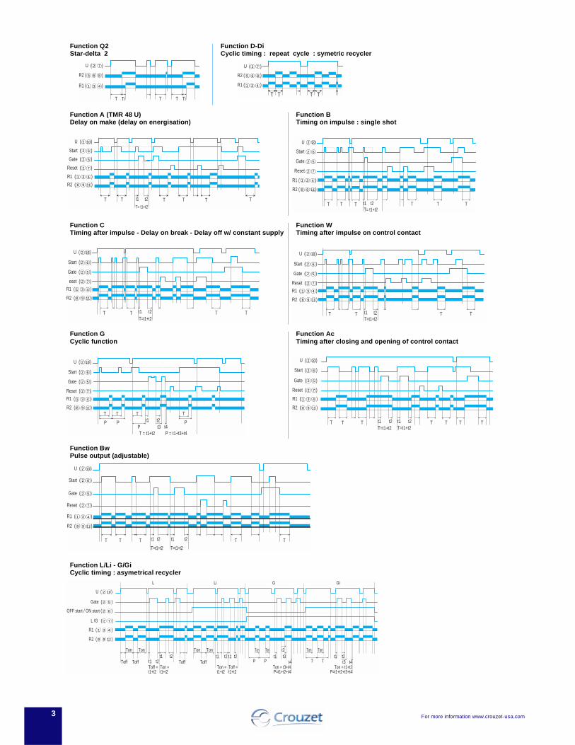
Function Q2Star-delta 2
Function D-DiCyclic timing : repeat cycle : symetric recycler
Function A (TMR 48 U) Delay on make (delay on energisation)
Function BTiming on impulse : single shot
Function CTiming after impulse - Delay on break - Delay off w/ constant supply
Function WTiming after impulse on control contact
Function GCyclic function
Function AcTiming after closing and opening of control contact
Function BwPulse output (adjustable)
Function L/Li - G/GiCyclic timing : asymetrical recycler
T Ti TT Ti
R2 ( )
R1 ( )
5 6 8
1 3 4
2 7U ( )
TT T T
R2 ( )
R1 ( )
5 6 8
1 3 4
U ( )2 7
t1 t2T TT= t1+t2
T T T T
U ( )2 10
Start ( )2 6
Gate ( )2 5
Reset ( )2 7
R1 ( )31 4
R2 ( )98 11
U
Start
Gate
Reset
t1 t2T= t1+t2
T T T T T
R2 ( )8 9 11
R1 ( )1 3 4
2 10
2 6
2 5
2 7
T
t1 t2T=t1+t2
TT T T
U ( )2 10
Start ( )2 6
Gate ( )2 5
eset ( )2 7
R1 ( )31 4
R2 ( )98 11
t1 t2T=t1+t2
TT T T
U ( )2 10
Start ( )2 6
Gate ( )2 5
Reset ( )2 7
R1 ( )31 4
R2 ( )98 11
t1 t2t3 t4
T = t1+t2
T
P
TT
P P
T
P
P = t1+t3+t4
U ( )2 10
Start ( )2 6
Gate ( )2 5
Reset ( )2 7
R1 ( )31 4
R2 ( )98 11
t1 t2T=t1+t2
t1 t2T=t1+t2
T T T T T T T
U ( )2 10
Start ( )2 6
Gate ( )2 5
Reset ( )2 7
R1 ( )31 4
R2 ( )98 11
t1 t2 t1 t2
T=t1+t2 T=t1+t2
TTT T T
U ( )2 10
Start ( )2 6
Gate ( )2 5
Reset ( )2 7
R1 ( )31 4
R2 ( )98 11
L Li G Gi
PP TT t4t3t4
Ton Ton
Toff Tofft1 t2 t1 t1 t1t2 t2 t1 t2t3
t1 t2 Toff Toff
Ton Ton
Toff =
Ton Ton Ton Tont2
Ton =t1+t2 t1+t2
Ton = t3+t4Ton =Toff =t1+t2 t1+t2 P=t1+t2+t4
Ton = t1+t2P=t1+t2+t3+t4
U ( )2 10
Gate ( )2 5
OFF start / ON start ( )2 6
L /G ( )2 7
R1 ( )31 4
R2 ( )98 11

TIMERS TIMERS
88220 SERIESMULTIFUNCTION MOTORTIMER WITH MEMORYUL listed CSA recognized
• Five Functions in One Unit
• Timing Range from 0.3 sec to 12 hours
• DIN-Rail, Plug-in, or Panel Mounting
SPECIFICATIONS:Input Power . . . . . . . . . . . . . . . . 24 VAC, 110 VAC, 220 VAC . . . . . . . . . . . . . . . . . . . . . . . . . . . ±10%, 60 HzMaximum power consumption . 3 VAOutput . . . . . . . . . . . . . . . . . . . . . 1 x SPST Relay & 1 x SPDT . . . . . . . . . . . . . . . . . . . . . . . . . . . RelayContact material . . . . . . . . . . . . . AgCdOMaximum loading . . . . . . . . . . . . 8 Amp 1/3 HPMaximum switching voltage . . . 220 VACMechanical life of relay . . . . . . . 2.5 million operationsRepeat accuracy . . . . . . . . . . . . . ±1.5% (except 4% on 6 sec . . . . . . . . . . . . . . . . . . . . . . . . . . . range)Setting Accuracy . . . . . . . . . . . . . +2% (except 5% on 6 sec . . . . . . . . . . . . . . . . . . . . . . . . . . . range)Reset time . . . . . . . . . . . . . . . . . 200 msStorage temp. rating . . . . . . . . . -20° to +70°C (-4° to 158°F)Operating temp. rating . . . . . . . . -20° to +55°C (-4° to 131°F)
FUNCTION AND WIRING DIAGRAMS:(Octal plug-in mounting shown)
DESCRIPTION:The 88220 Series is a synchronous motor driven reset timer. Thetimer is available in 2 standard time ranges from 0.3 sec to 12hours. Time ranges are knob adjustable and all have a progresspointer which displays the remaining time. Different functions (ONDelay, Interval, One Shot) selectable through external wiring.
12
34 5
6
78
Load
N.O.Start
AC Supply
Power(Start Switch)
OutputDelay
12
34 5
6
78
Load
N.O.Start
AC Supply
Power(Start Switch)
OutputDelay
12
34 5
6
78
N.O.StartAC Supply
MomentaryContact
OutputDelay
Load
12
34 5
6
78
Load
N.O.Start
AC Supply
MomentaryContact
OutputDelay
12
34 5
6
78
N.O.Start
AC Supply
MomentaryContact
OutputDelay
Reset
Load
1
2
3
4 5
6
7
8
A1 15 24 23
16 18 A2
12345678
=
=
=
=
=
=
=
=
24A123--1618A215
"ON DELAY" Maintained Start Switch
"INTERVAL" Maintained Start Switch
"ON DELAY" Momentary Push Button
"INTERVAL" Momentary Push Button
"ONE SHOT" CROSS REFERENCE TABLE FOR:
Octal Plug Pins = Screw Terminals
Type 88 225 0 (DIN - rail mounting)
.20
(5.2
)
with memory
without memory
1.97
(50
)
2.16
(55
)
2.36
(60
)
2.46
(62
.5)
1.48(37.5)
1.38(35)
.16(4.2)
1.77(45)
2.75
(70
)
3.19 (81)
3.58 (91)
Type 88 226 0 (paneling mounting)
Nut
M3
3.27 (83)
1.89
(48)
1.89(48)
Max. Thickness
of panel .39 (10)
3.94 (100).47(12)
1.71
(45)
Panel cut-out
1.81(46)
1.81
(46)
DIMENSIONS: inches (mm)
1
2
3
4 5
6
7
8
1.89
(48)
1.89(48)
FIXED
4.05 (103)
3.03 (77)
.51(13)
3.54 (90)
Max. Thickness
of panel .39 (10)
1.17
(45
)
Type 88 226 5 (octal plug-in)
Products and specifications subject to change without notice.Consult factory for application assistance.
204 Airline Drive, Suite 300, Coppell, Texas 75019 / Tel: (800) 677-5311 / FAX: (800) 677-3865 / www.crouzet-usa.com4-8
(panel mounting accessories included)

TIMERS TIMERS
4
Products and specifications subject to change without notice.Consult factory for application assistance.
204 Airline Drive, Suite 300, Coppell, Texas 75019 / Tel: (800) 677-5311 / FAX: (800) 677-3865 / www.crouzet-usa.com4-9
MULTI-FUNCTIONon-delay, intervaland single shot inon timer
ADAPTER PLATEavailable for fieldinterchangeability(not shown)
TIME RANGESModel 1 (12 min.): .3 to 6 s, .5 to 12 min.Model 2 (12 hrs.): .3 to 6 min., 3 to 60 min, .5 to 12 hrs.
MULTI-RANGE2 model/3 time rangeseach coverfrom 0.3 sec to 12 hours CYCLE PROGRESS
dial showstime remainingin cycle
MEMORYwhen “on,”holds timeduring powerinterruption
TRANSIENTIMMUNITYBuilt-in
±2% SETTINGACCURACY
±1.5% REPEATACCURACY
GENERAL FEATURES:
ORDERING INFORMATION:When ordering, select model, voltage/frequency andmounting to determine part number in chart below
EXAMPLEMODEL 1 (12 MIN.), 115V/60Hz, OCTAL PLUG-IN, 88 226 510
OFF ONMEMORY
MODELING
OCTAL PLUG-IN(PART NUMBER)
MODEL VOLTAGE/FREQ.* BASE MOUNTING(PART NUMBER)
PANEL MOUNTING(PART NUMBER)
MODEL 1 (12 MIN.)
MODEL 1 (12 MIN.)
MODEL 1 (12 MIN.)
MODEL 1 (12 MIN.)
MODEL 2 (12 HRS.)
MODEL 2 (12 HRS.)
MODEL 2 (12 HRS.)
MODEL 2 (12 HRS.)
24 V/60 Hz
115 V/60 Hz
220 V/60 Hz
220 V/50 Hz
24 V/60 Hz
115 V/60 Hz
220 V/60 Hz
220 V/50 Hz
88 226 509
88 226 510
88 226 511
88 226 504
88 226 512
88 226 513
88 226 514
88 226 508
88 226 029
88 226 030
88 226 031
88 226 011
88 226 032
88 226 033
88 226 034
88 226 014
88 225 029
88 225 030
88 225 031
88 225 011
88 225 032
88 225 033
88 225 034
88 225 014

TIMERS TIMERS
4
When input power (S1) is applied, the relay delays the preset time (T)period prior to energizing. Interrupt power to unlatch the relay.
SPECIFICATIONS:Input Power . . . . . . . . . . . . . . . 24 VAC/DC, 110 VAC
220 VAC ±15% 50/60 HzMax. Power Consumption . . . . 24 VDC: 0.6 W 110 VAC: 3.5 VA
24 VAC: 1 VA 220 VAC: 7 VAOutput. . . . . . . . . . . . . . . . . . . . DPDT RelayContact Material . . . . . . . . . . . . AgCdOMax. Loading . . . . . . . . . . . . . . 5 Amp AC resistive 5 Amp DC resistiveMin. Loading . . . . . . . . . . . . . . . 100 mA AC resistiveMax. Switching Voltage . . . . . . 240 VAC 250 VDCMax. Power Rating . . . . . . . . . . 1200 VA 150 WMechanical Life of Relay . . . . . 20 million operationsElectrical Life of Relay . . . . . . . 100.000 operations at 1200 VARepetition Accuracy. . . . . . . . . ±1% at constant temperatureSetting Error . . . . . . . . . . . . . . . ±10%Reset Time . . . . . . . . . . . . . . . . 50 ms after Timing
100 ms during TimingOperating Temperature . . . . . . +14°F to +140°F (-10°C to +60°C)Humidity . . . . . . . . . . . . . . . . . . 35 to 85%Dielectric Strength . . . . . . . . . . 2000 VAC 50 Hz for 1 min.Weight. . . . . . . . . . . . . . . . . . . . 1.9 oz. (60g)
TOP 36 SERIESDELAY ON MAKE TIMERUL listed CSA recognized
• DIN-Sized (36 x 36mm) Housing
• Low Cost
• Solid State Technology
• 5 Amp DPDT Relay
• LED Power On Indicator
T0
Delay on MakeDelay on Make 61 (2.40)36 (1.42)
UNUN
Sec
.05 51 4
2 3
73 (2.87)88 (3.46)
5(.2)
27 (
1.06
)
36 (
1.42
) 32,8 (1.29)
1 8
2 7
3R2R2 R1R1
6
4
S1
ZAR2
5
36 (1.42)40
,5 (
1.59
)
33 (1.29)
33 (1.29)
+0.5 -0
Function: A2
Input Power
RelayR1 R2
DIMENSIONS:
WIRING DIAGRAM:
CUT OUT: inches (mm) MOUNTING CLIP:
.05 to 5 sec
.6 to 60 sec3 to 300 sec.3 to 30 min
ORDERING INFORMATION: (10 pcs. minimum)
Part Number Time Range
24 VAC/VDC Version88 888 111 88 888 13188 888 15188 888 171
110 VAC Version88 888 115 88 888 13588 888 15588 888 175
220 VAC Version88 888 11788 888 13788 888 15788 888 177
Products and specifications subject to change without notice.Consult factory for application assistance.
204 Airline Drive, Suite 300, Coppell, Texas 75019 / Tel: (800) 677-5311 / FAX: (800) 677-3865 / www.crouzet-usa.com4-13

.05 to 1 sec
.5 to 10 sec3 to 60 sec.5 to 10 min
3 m to 60 min
ORDERING INFORMATION: (10 pcs. minimum)Part Number Time Range
24 VDC Version88 901 302 88 901 32288 901 34288 901 37288 901 392
110/220 VAC Version88 901 308 88 901 32888 901 34888 901 37888 901 398
01010202
03031 to 8
47.5
22.3mm+0.4-0
29
22
TIMERS TIMERS
DESCRIPTION:The 88 901 Series is a front panel mount analog timer with a NEMA4 front panel. The unit is available in a 2 wire AC (110/220 V) or 3Wire DC (24 V PNP Transistor) Configuration. The unit can drive acontactor or be connected, for the 3 wire DC version, between theinput and the output of a PLC for remote setting of a time variable.The delay on make timer is available in 10 different time ranges from1 sec. to 30 min. The device is protected against reverse polarity andshort-circuit.
SPECIFICATIONS: 3 Wire 2 Wire
Input Power . . . . . . . . . . . . . . . 24 VDC 90 to 260 VACOutput. . . . . . . . . . . . . . . . . . . . PNP Open Collector SCRMax. Current at 20°C . . . . . . . . 200 mA 400 mAOff State Voltage Drop . . . . . . . < 3 VDC < 4 VACDerating . . . . . . . . . . . . . . . . . . 1.5 mA/°C 2.5 mA/°COff State Leakage Current . . . . < 1 mA < 4 mAMax. Reset Time: during timing 20 ms 120 ms
after timing . 20 ms 15 msDisplay Accuracy . . . . . . . . . . . ±5% ±5%Repeat Accuracy . . . . . . . . . . . ±0.2% ±0.2%Dielectric Strength . . . . . . . . . . 1500 V/1 min. 1500 V/1 min.Power Consumption. . . . . . . . . 1 W 1.5 VAConnections . . . . . . . . . . Screw TerminalsTemperature Range . . . . -4°F to 140°FWeight . . . . . . . . . . . . . . 8 oz.
DIMENSIONS: (mm)
FUNCTION:Delay on Make
WIRING:3 Wire DC
with Relay/Contactor with PLC
01 - Output of programmable controller02 - Input of programmable controller03 - Load
2 Wire Ac
18
A2A1 03
+
18
A2A1
02
01
+
O-
|
A1
A2
LoadA
(-)(+)(+)
(-)(+)(+)
A1-A2
18T
88 901 SERIESDELAY ON MAKE TIMER
• 22mm Panel Mount Timer
• 2 Wire AC or 3 Wire DC
• PLC Compatible
• NEMA 4 Rating
(-)(+)
(-)(+)
Products and specifications subject to change without notice.Consult factory for application assistance.
204 Airline Drive, Suite 300, Coppell, Texas 75019 / Tel: (800) 677-5311 / FAX: (800) 677-3865 / www.crouzet-usa.com4-14

TIMER ACCESSORIES TIMER ACCESSORIES
4
Accessories For M/G Series(48 x 48mm Timers)
1032 - Retrofit Panel Plate
33.5 MM
2.8125" (71.43mm)2.8125" (71.43mm)
2.8125" (71.43mm
)
1.8" (46mm)1.8" (46mm)
1.8" (46mm
)1.8" (46m
m)
4.250" (108mm)4.250" (108mm)
3.8125" (96.83mm
)3.8125" (96.83m
m)
The 1032 panel plate has been designed for use with the M/G/FAXR2, MGF 813 & 11614 Series.It will retrofit:ATC 366, 353, 336, 335, 334, 333 & 310 SeriesEagle CX 300, CT 540, CT 51, CT 530, CD300
HP 5, HP 4, BR 4, CE 500 & H2170
831 - Hard Protective Cover (NEMA 4)SA8NN & SA11NN - Back connecting Socket
1.77
18 58
1.77
1.77
18 58
1.77
Products and specifications subject to change without notice.Consult factory for application assistance.
204 Airline Drive, Suite 300, Coppell, Texas 75019 / Tel: (800) 677-5311 / FAX: (800) 677-3865 / www.crouzet-usa.com4-15
SA11NN SA8NN

4
4/26
Multi-function or mono-function Multi-range (7 ranges, available options) Multi-voltage Relay output 1 or 2: 8 A - 250 V (10 A UL) Plug-in 1 LED status indicators Option of connecting an external power supply to the
control input 3-wire sensor control option
Chronos 2 electronic timers - Plug-in 8-pin (35 mm)
Relay output 1 or 2 DPDT relays
Types
Part numbers and voltage24V c / 24 • 240V a12 V a / c12 • 240 V a / cFunctions
Nominal currentAccessories8-pin connector base (for the whole range) S08
Timing ranges (7 ranges)0.1s - 1s - 10 s , 6s - 60s , 1 min - 10 min , 6min - 60min , 1 h - 10 h - 100 h
Timing
± 0.5 % (CEI 1812-1)
± 0.05 % / °C± 0.2 % / V±10 % / 25 °C
30 ms
100 ms
100 ms
>10 ms
depending on version,see page 1/2150/60 Hz85 to 110 % Un(85 to 120 % Un for12V AC/DC)100 %0.6 W 24V AC/DC1.5 W 230V AC32 VA 230V AC
2000 VA / 80 W2000 V A / 80W10 A AC 10 A DC10 mA / 5 VDC250V AC/VDC105 operations 10 A 250V resistive5 x 106 operations2.5 kV / 1min / 1 mA /50Hz5 kV, wave 1.2 / 50 µs
0.4 V
-20 °C + 60 °C-30 °C + 60 °CVoltage surgecategory
4 kV / 3
IP 20IP 40IP 50 f = 10 • 55 Hz A = 0.35 mm
93 %Level III (Air 8 K / Contact 6 KV)Level III 10V/m:80 MHz to 1 GHz)Level III (direct 2kV/Capacitive couplingclamp 1 KV)Level III (commonmode 2 KV / residualcurrent mode 1KV)Level III (10V rms:0.15 MHz to 80 MHz)
30 % / 10 ms60 % / 100 ms > 95 % / 5 s
Class B8-pin Self-extinguishing80 g
General specificationsConforming to standardsIEC 1812-1, EN 50081-1/2, EN 50082-1/2, LVdirectives (73/23/EEC + 93/68/EEC (CE marking) + EMC (89/336/EEC + IEC 669-2-3 (17.5 mm) Approvals UL - CSA - cUL listedTemperatures limits- use- storedInstallation category (acc. to IEC 664-1)
Creepage distance and clearance acc. to IEC 664-1Degree of protection acc. to IEC 529- terminal block- casing - front face (except Tk2R1)Vibration resistance acc. to IEC 68-2-6
Relative humidity acc. to IEC 68-2-3 without condensationElectromagnetic compatibility- Immunity to electrostatic discharges acc. toIEC 1000-42- Immunity to electrostatic fields acc. to ENV 50140/204 (IEC 1000-4-3)- Immunity to rapid transient bursts acc. to IEC1000-4-4
- Immunity to shock waves on power supply acc.to IEC 1000-4-5
- Immunity to radiofrequency in common modeacc. to ENV
- Immunity to voltage dips and breaks acc. toIEC 1000-4-11
- Mains-borne and radiated emissions acc. toEN 55022 (EN 55011 Group 1)Fixing: plug-in bases Casing material Weight: plug-in casing
Other information
TimingRepetition accuracy (with constant parameters) Drift- Temperature- Voltage Display precision according to IEC 1812-1Minimum pulse duration - Typically
- Typically under load Maximum reset time by de-energisation
- Typically
Immunity to breaks in supply voltage: typicallyPower supplyMulti-voltage power supply
Frequency Operating range
Load factor Maximum power consumption
Output elements relay output1 or 2 changeover relays, AgNi (cadmium-free)Rated power Maximum breaking currentMinimum breaking currentVoltage breaking capacityElectrical life
Mechanical lifeBreakdown voltage acc. to IEC 1812-1
Impulse voltage acc. to IEC 664-1 IEC 1812-1DisplayState displayed by 1 LED - Flashing green when onGreen LED operation indicator
Pulsing:- timer on, no timing in progress(except functions Di-D and Li-L)
Flashing:- timing in progress
Permanently lit:- Relay waiting, no timing in progress
Input type- Volt-free contact- 3-wire PNP output control option maximumresidual voltage: 0.4 V whatever the timer powersupply
Technical specifications
Non stocked items, minimum order quantity 100 units.
88 867 305
Mono-functionL
10 A
2 timers
0.1s • 100h
PU2R1
optional connector base 25 622 128
For special features, functions, etc. Please contact us.

4
4/27
88 867 155--
BifunctionLi - L
10 A
1 timer
88 867 135--
Mono-functionC
10 A
1 timer
88 867 215--
Mono-functionA
10 A
2 timers
88 867 105--
Multi-functionA - At - B - C - H - Ht -Di - D - Ac - Bw10 A
1 timer
0.1s • 100h
OUR1
0.1s • 100h
OA2R1
0.1s • 100h
OCR1
0.1s • 100h
OLR1
-88 867 100
-Multi-functionA - At - B - C - H - Ht -Di - D - Ac - Bw10 A
1 timer
0.1s • 100h
OUR4
--
88 867 103Multi-functionA - At - B - C - H - Ht -Di - D - Ac - Bw10 A
1 timer
0.1s • 100h
OUR3
2
3
1
Functions :A - At / H - Ht / B / C Li ADi - D / Ac / BW L :
Connections: 8-pin 1 relay 8-pin 2 relay
U4
R
Y1+
–
5
6
7
81
2
3
U4
R1 R2
+
–
5
6
7
81
2
3
U
4
R
+
–
5
6
7
81
2
3
Function diagrams
Function ADelay on energisation1 relay
Function CTiming after impulse1 timer
Function HTiming on energisation1 relay
2 timers
U
R1/R2T
U
RT
U
C
Rt1 t2
T = t1+t2
U
C
R∞ T
U
C
R∞ T
TR
U
Function HtDelay on energisation with memory1 relay
t1R
C
U
t2T = t1+t2
Function DFlip-flop 1 relayPause start
U
T TR
Function DiFlip-flop 1 relayPulse start
U
RT T
Function AcTiming after closing and openingof control contact 1 relay
U
C
RT T
Function BwPulse output (adjustable) 1 relay
U
C
RT T
Dimensions
45
3,5 12,574,5
35
Function LAsymmetrical recycler 1 relayPause start
T1R
T2
U
Function LiAsymmetrical recycler 1 relayPulse start
T1R
U
T2
Type Part number Part number
Example: Chronos 2 Timers OUR1 88 867 105 8-pin connector base 25 622 128
321Standard products
To order, specify:
H
2 6
Accessorie
8-pin connector baseS08
Function AtTiming on energisation with memory1 relay
Function BTiming on impulse one shot1 relay
Y1=C (function diagrams) For hold down clamps use p/n 25 532 770 and base p/n 25 622 128

4
4/28
Multi-function or mono-function Multi-range (7 ranges, available options) Multi-voltage Relays output 1: 8 A - 250 V (10 A UL) Plug-in 1 LED status indicators Option of connecting an external power supply to the
control input 3-wire sensor control option
Chronos 2 electronic timers - Plug-in 11-pin (35 mm)
Relay output 2 change over relays
Types
Part numbers and voltage24V c / 24 • 240V a12 V a / c12 • 240 V a / cFunctions
Nominal currentAccessorie11-pin connector base (for the whole range) S11 25 622 077
Timing ranges (7 ranges)0.1s - 1s - 10 s , 6s - 60s , 1 min - 10 min , 6min - 60min , 1 h - 10 h - 100 h
Timing
± 0.5 % (CEI 1812-1)
± 0.05 % / °C± 0.2 % / V±10 % / 25 °C
30 ms50 ms100 ms
100 ms350 ms>10 ms
depending on version,see page 1/1350/60 Hz85 to 110 % Un(85 to 120 % Un for12V AC/DC)100 %0.6 W 24V AC/DC1.5 W 230V AC32 VA 230V AC
2000 VA / 80 W2000 V A / 80W 10A AC 10 A DC10 mA / 5 VDC250V AC/VDC105 operations 10 A 250V resistive5 x 106 operations2.5 kV / 1min / 1 mA /50Hz5 kV, wave 1.2 / 50 µs
0.4 V
-20 °C + 60 °C-30 °C + 60 °CVoltage surgecategory
4 kV / 3
IP 20IP 40IP 50 f = 10 • 55 Hz A = 0.35 mm
93 %Level III (Air 8 K / Contact 6 KV)Level III 10V/m:80 MHz to 1 GHz)Level III (direct 2kV/Capacitive couplingclamp 1 KV)Level III (commonmode 2 KV / residualcurrent mode 1KV)Level III (10V rms:0.15 MHz to 80 MHz)
30 % / 10 ms60 % / 100 ms > 95 % / 5 s
Class B11-pin Self-extinguishing80 g
General specificationsConforming to standardsIEC 1812-1, EN 50081-1/2, EN 50082-1/2, LVdirectives (73/23/EEC + 93/68/EEC (CE marking) + EMC (89/336/EEC + IEC 669-2-3 (17.5 mm) Approvals UL - CSA - cUL listedTemperatures limits- use- storedInstallation category (acc. to IEC 664-1)
Creepage distance and clearance acc. to IEC 664-1Degree of protection acc. to IEC 529- terminal block- casing - front face (except Tk2R1)Vibration resistance acc. to IEC 68-2-6
Relative humidity acc. to IEC 68-2-3 without condensationElectromagnetic compatibility- Immunity to electrostatic discharges acc. toIEC 1000-42- Immunity to electrostatic fields acc. to ENV 50140/204 (IEC 1000-4-3)- Immunity to rapid transient bursts acc. to IEC1000-4-4
- Immunity to shock waves on power supply acc.to IEC 1000-4-5
- Immunity to radiofrequency in common modeacc. to ENV
- Immunity to voltage dips and breaks acc. toIEC 1000-4-11
- Mains-borne and radiated emissions acc. toEN 55022 (EN 55011 Group 1)Fixing: plug-in bases Casing material Weight: plug-in casing
Other information
TimingRepetition accuracy (with constant parameters) Drift- Temperature- Voltage Display precision according to IEC 1812-1Minimum pulse duration - Typically (relay version)- Typically (solid state version)- Typically under load (relay version)Maximum reset time by de-energisation
- Typically (relay version)- Typically (solid state version)Immunity to breaks in supply voltage: typicallyPower supplyMulti-voltage power supply
Frequency Operating range
Load factor Maximum power consumption
Output elements relay output1 or 2 changeover relays, AgNi (cadmium-free)Rated power Maximum breaking currentMinimum breaking currentVoltage breaking capacityElectrical life
Mechanical lifeBreakdown voltage acc. to IEC 1812-1
Impulse voltage acc. to IEC 664-1 IEC 1812-1DisplayState displayed by 1 LED - Flashing green when onGreen LED operation indicator
Pulsing:- timer on, no timing in progress(except functions Di-D and Li-L)
Flashing:- timing in progress
Permanently lit:- Relay waiting, no timing in progress
Input type- Volt-free contact- 3-wire PNP output control option maximumresidual voltage: 0.4 V whatever the timer powersupply
Technical specifications
Non stocked items, minimum order quantity 100 units.For special features, functions, etc. Please contact us.

4
4/29
Functions :A - At / H - Ht / B / C Li Di - D / Ac / BW L :
88 867 455--
BifunctionLi - L
10 A
2 timers
88 867 435--
Mono-functionC
10 A
2 timers
88 867 415--
BifunctionA - At
10 A
2 timers
88 867 305--
Multi-functionA - At - B - C - H - Ht -Di - D - Ac - Bw10 A
2 timers including 1instantaneous
0.1s • 100h
PU2R1
0.1s • 100h
PA2R1
0.1s • 100h
PC2R1
0.1s • 100h
PL2R1
-88 867 300
-Multi-functionA - At - B - C - H - Ht -Di - D - Ac - Bw10 A
2 timers including 1instantaneous
0.1s • 100h
PU2R4
--
88 867 303Multi-functionA - At - B - C - H - Ht -Di - D - Ac - Bw10 A
2 timers including 1instantaneous
0.1s • 100h
PU2R3
2
3
1
U
4R1
Y1
R2
+
–
56
7
8
9
10111
2
3
U
4R1 R2
+
–
56
7
8
9
10111
2
3
Connections Y1=C (function diagrams) Dimensions
45
3,5 12,574,5
35
Function diagrams
Function ADelay on energisation2 timers or2 relays, including 1 instantaneous
Function CTiming after impulse2 timers or 2 relays, including 1 instantaneous
Function HTiming on energisation2 timers or 2 relays, including 1 instantaneous
Function AtTiming on energisation with memory2 timers or2 relays, including 1 instantaneous
U
R1/R2
R2 INSTT
U
C
R1/R2t1 t2
T = t1+t2R2 Inst.
U
C
R1/R2∞ T
R2 Inst.
TR1/R2
U
R2 Inst.
Function HtDelay on energisation with memory2 timers or 2 relays, including 1 instantaneous
t1R1/R2
C
U
t2
T = t1+t2R2 Inst.
Fonction DFlip-flop Pause start2 timers or 2 relays, including 1 instantaneous
U
T TR1/R2
R2 Inst.
Fonction DiFlip-flop Pause start2 timers or 2 relays, including 1 instantaneous
U
R1/R2T T
R2 Inst.
Function AcTiming after closing and openingof control contact 2 timers or 2 relays, including 1 instantaneous
U
C
R1/R2T T
R2 Inst.
Function BwPulse output (adjustable) 2 timers or 2 relays, including 1 instantaneous
U
C
RT T
U
C
R1/R2
∞ TR2 inst.
Type Part number Accessorie
Example: Chronos 2 Timers PU2R1 88 867 305 11-pin connector base 25 622 077
321Standard products
To order, specify:
H
Function BTiming on impulse one shot2 timers or 2 relays, including 1 instantaneous
T1R1/R2
T2
U
Function LiAsymmetrical recycler 1 relayPulse start2 timers
T1R1/R2
U
T2
2 5
Accessorie
11-pin connector base S11
Function LAsymmetrical recycler 1 relayPause start2 timers
p/n 25 532 770 and base p/n 25 622 077For hold down clamps use

4
4/i
Function C: Timing after impulseDelay OFF (with constant supply
After energisation, once the control contact isclosed the output state changes.Timing will only begin on the re-opening ofthis control contact (one shot).Relay R returns to its initial position at theend of the timing period.
Function D or Di: Flip-flop
Repetitive cycle which switches the outputalternately between the rest and operatingposition for equal time bases.T1 + T2 = T total
Function D: the cycle begins with the outputin rest position. Pause start.
Function Di: the cycle begins with the outputin the operating position. Pulse start.
Function H: Timing on energisationInterval timer - one shot
On energisation, the output changes state,remains in that state for the duration of timingand resets at the end of the single cycle.
N.B. This is complementary to function A.
Function B: Timing on impulse one shotOn pulse (with constant supply)
After energisation; a pulse (≥ 50 ms) or amaintained control contact will cause theoutput to change state which reverts to therest position at the end of timing.
N.B. : this process enables shortening orlengthening of a signal.
Function Bw: Pulse output (adjustable)
AOutput relay R (or the load) changes state,and remains in the changed-over state for thetiming period, both when control contact C(Y1) closes and when it opens.
U : Supply C (Y1) : Control contactR : Output or load relayT : Timing : indefinite
Function A: Delay on energisation
Single timing cycle which begins onenergisation.
The output changes state after timing.
Function Ab: One-shot cycle
The output changes states at the end of theset time T1, for a period T2.Both T1 and T2 independently adjustable.
Function Ac: Timing after closing and opening of control contact
After energisation, closure of the controlcontact causes the timing period T tocommence and output relay R (or the load)changes state at the end of this interval.When contact C (Y1) opens, relay R resetsafter a second timing period T. .
Function Ad :Delay on energisation by switch (not resettable)
After power-up, pressing or holding downthe switch starts timing. At the end of timing,the output is energised. The outputwill be reset the next time the switch ispressed or held down.
Function Ah : Flashing single cycle by switch (not resettable)
After power-up, pressing or holding downthe switch starts timing. At the end of timing,the output is energised. At the end of thissecond timing, the output falls back to its initial value.
Function At: Timing on energisation with memory
Provides a cumulative time for contactopening.
The output changes states at the end of theset time.
U
R1/R2
R2 INSTT
U
RT
U
RT1 T2
U
C
RT T
U
C
Rt1 t2
T = t1+t2
U
C
R1/R2t1 t2
T = t1+t2R2 Inst.
U
C
RT
U
C
R1/R2T
R2 Inst.
U
C
RT T
U
C
RT T
U
C
RT
U
C
R1/R2
TR2 inst.
Functions
U
C
R1/R2T T
R2 Inst.
U
C
RT T
1 relay
2 relays timed or 1 relay timed and 1 instantaneous
1 relay
2 relays timed or 1 relay timed and 1 instantaneous
1 relay
1 relay
U
C
R1/R2
R2 Inst.T T T T
2 relays timed or 1 relay timed and 1 instantaneous
1 relay
2 relays timed or 1 relay timed and 1 instantaneous
1 relay
2 relays timed or 1 relay timed and 1 instantaneous
1 relay
2 relays timed or 1 relay timed and 1 instantaneous
U
T TR
U
T TR1/R2
R2 Inst.
U
RT T
U
R1/R2T T
2 Inst.
1 relay
1 relay
2 relays timed or 1 relay timed and 1 instantaneous
2 relays timed or 1 relay timed and 1 instantaneous
TR
U
TR1/R2
U
R2 Inst.
1 relay
2 relays timed or 1 relay timed and 1 instantaneous

4
4/ii
Function P : Delayed fixed-length pulse
Timing begins on energisation. At the end ofthe timing period output relay R (or the load)changes state for a period of approx. 500milliseconds.
Function Pt : Impulse counter (delay on)
Calculates the total opening time of a contact.At the end of timing, the output is energisedfor approximately 500 ms.
Function Q : Star-delta"
At the end of timing, the output is notenergised. It remains "open" (notconducting) and will only change stateafter the fixed time of Ti has elapsed.Dwell time selectable
Function T : Timing onenergisation with memory
a - energisation by control signalThe timer sums the times for which thecontrol contact is closed (C1).Reset is by the reset signal (C2) only.
b - energisation by supply voltageThe timer sums the times for which thesupply voltage (U) is on.Reset is by the reset signal (C2) only
Function T : Impulse relay
After power-up, pressing or holding down the switch closes the relay. Pressing the switch a second time opens the relay.
Function Tt : Timed impulse relay
After power-up, pressing or holding down the switch closes the relay and starts timing. Therelay opens at the end of timing or when theswitch is pressed a second time.
Function W : Timing after pulse on control contact
After energisation, if the control contactopens it causes output relay R (or the load)to change state and timing to start. At theend of the timing period, relay R resets to itsoriginal state.
Function L : Cyclic timing - Asymmetrical recycler
Repetitive cycle comprising 2 independentadjustable time bases. Each time basecorresponds alternately to a different outputstate.
N.B. : The cycle starts with the output in therest position.
Function Li : Cyclic timing - Asymmetrical recycler
Repetitive cycle comprising 2 independentadjustable time bases. Each time basecorresponds alternately to a different outputstate.
N.B. : The cycle starts with the output in theoperating position.
Function N : "Safe-guard"
At the first control pulse the output isenergised.To complete the timing the interval betweenthe two control pulses must be greater thanthe timing set.
Function O : "Delayed safe-guard".
On energisation, a first timing sequenceoccurs and the output changes state.With the closing of the control contact, theoutput resets and the timing starts, with theoutput being activated after timing.For the timing to be completed, the intervalbetween the closing of two control contactsmust be greater than the timing set.
T1R
T2
U
T1R
U
T2
T
R
C
U
T T
U
RT P
P = 500 ms
TR
U
Ti
U
C
Rt1 t2 PT= t1+t2
TR
C
U
U
C
RT t
8 8 8
U
C
R
TR
C
U
T1R1/R2
T2
U
T1R1/R2
U
T2
1 relay
2 relays timed or 1 relay timed and 1 instantaneous
1 relay
2 relays timed or 1 relay timed and 1 instantaneous
Function Ht : Delay on energisation with memory
Provides a cumulative time for contact opening.On energisation, the output changes state,remains in that state for the duration of timing and resets at the end of the single cycle.
Function K: Delay on de-energisation - True delay OFF
On energisation, the output changes state.On de-energisation timing commences andthe output only returns to the reset conditionafter timing.
TR
U
t1R
C
U
t2T = t1+t2
t1R1/R2
C
U
t2
T = t1+t2R2 Inst.
1 relay
2 relays timed or 1 relay timed and 1 instantaneous
1 relay
2 relays timed or 1 relay timed and 1 instantaneous
TR2
U
R1

4
4/18
± 0.5 % (CEI 1812-1)
± 0.05 % / °C± 0.2 % / V±10 % / 25 °C
30 ms50 ms100 ms
100 ms350 ms>10 ms
depending on version,see page 1/1350/60 Hz85 to 110 % Un(85 to 120 % Un for12V AC/DC)100 %0.6 W 24V AC/DC1.5 W 230V AC32 VA 230V AC
2000 VA / 80 W2000 V A / 80W10 AAC 10 A DC10 mA / 5 VDC250V AC/VDC105 operations 8 A 250V resistive5 x 106 operations2.5 kV / 1min / 1 mA /50Hz5 kV, wave 1.2 / 50 µs
0.4 V
TypesScrew terminals MUR1 MAR1Spring terminals - -Part numbers and voltage24V dc / 24 • 240V acc8 8826 105 88 826 115 12 V ac / dc - -12 • 240 V ac / dc - -Functions Multi-function Bifunction
A - At - B - C - H - Ht - A - AtDi - D - Ac - Bw
Nominal current 10 A 10 A
Timing ranges (7 ranges)0.1s - 1s - 10 s , 6s - 60s , 1 min - 10 min , 6min - 60min , 1 h - 10 h - 100 h
-20 °C + 60 °C-30 °C + 60 °CVoltage surgecategory
4 kV / 3
IP 20IP 40IP 50 f = 10 • 55 Hz A = 0.35 mm
93 %Level III (Air 8 K / Contact 6 KV)Level III 10V/m:80 MHz to 1 GHz)Level III (direct 2kV/Capacitive couplingclamp 1 KV)Level III (commonmode 2 KV / residualcurrent mode 1KV)Level III (10V rms:0.15 MHz to 80 MHz)
30 % / 10 ms60 % / 100 ms > 95 % / 5 s
Class B35 mm
2 x 2.5 mm2
2 x 1.5 mm2
1.5 mm2
2.5 mm2
Self-extinguishing60 g
General specificationsConforming to standardsIEC 1812-1, EN 50081-1/2, EN 50082-1/2, LVdirectives (73/23/EEC + 93/68/EEC (CE marking) + EMC (89/336/EEC + IEC 669-2-3 (17.5 mm) Approvals UL - CSA - cUL listedTemperatures limits- use- storedInstallation category (acc. to IEC 664-1)
Creepage distance and clearance acc. to IEC 664-1Degree of protection acc. to IEC 529- terminal block- casing - front face (except Tk2R1)Vibration resistance acc. to IEC 68-2-6
Relative humidity acc. to IEC 68-2-3 without condensationElectromagnetic compatibility- Immunity to electrostatic discharges acc. toIEC 1000-42- Immunity to electrostatic fields acc. to ENV 50140/204 (IEC 1000-4-3)- Immunity to rapid transient bursts acc. to IEC1000-4-4
- Immunity to shock waves on power supplyacc. to IEC 1000-4-5
- Immunity to radiofrequency in common modeacc. to ENV
- Immunity to voltage dips and breaks acc. toIEC 1000-4-11
- Mains-borne and radiated emissions acc. toEN 55022 (EN 55011 Group 1)Fixing: Symmetrical DIN rail (EN 50022) Connection capacity- without ferrule- with ferruleSpring terminals, 2 terminals perconnection point- flexible wire- rigid wireCasing material Weight : 17.5 mm casing
Multi-function or mono-function Multi-range (7 ranges, available options) Multi-voltage 1 changeover relay output: 8A - 250 V (10 A UL) Screw or spring terminals 1 LED status indicators Option of connecting an external power supply to the
control input 3-wire sensor control option
Other information
Chronos 2 electronic timers - 17.5 mm
TimingRepetition accuracy (with constant parameters) Drift- Temperature- Voltage Display precision according to IEC 1812-1Minimum pulse duration - Typically (relay version)- Typically (solid state version)- Typically under load (relay version)Maximum reset time by de-energisation
- Typically (relay version)- Typically (solid state version)Immunity to breaks in supply voltage: typicallyPower supplyMulti-voltage power supply
Frequency Operating range
Load factor Maximum power consumption
Output elements relay output1 or 2 changeover relays, AgNi (cadmium-free)Rated power Maximum breaking currentMinimum breaking currentVoltage breaking capacityElectrical life
Mechanical lifeBreakdown voltage acc. to IEC 1812-1
Impulse voltage acc. to IEC 664-1 IEC 1812-1DisplayState displayed by 1 LED - Flashing green when onGreen LED operation indicator
Pulsing:- timer on, no timing in progress(except functions Di-D and Li-L)
Flashing: - timing in progress
Permanently lit:- Relay waiting, no timing in progress
Input type- Volt-free contact- 3-wire PNP output control option maximumresidual voltage: 0.4 V whatever the timerpower supply
Technical specifications
1 DPDT relay output
Non stocked, minimum order quantity 100 units.
Timing 0.1s • 100h 0.1s • 100h

4
4/19
Function diagrams
Connections Y1=C (function diagrams)
U
A1R
15
A21816
Y1
+U
A1R
15
A21516
Y1
+
Dimensions
5,5
81
17,5
60
45
443,5
Function ADelay on energisation1 relay
Function HTiming on energisation1 relay
U
RT
U
C
Rt1 t2
T = t1+t2
U
C
RT
TR
U
Function HtDelay on energisation with memory1 relay
t1R
C
U
t2T = t1+t2
Fonction LDouble temporisation 1 relaisDémarrage par pause
T1R
T2
U
T1R
U
T2
Function DFlip-flop 1 relayPause start
U
T TR
Function DiFlip-flop 1 relayPulse start
U
RT T
Type Part number
Example: Chronos 2 Timers MUR1 88 826 105
21
To order, specify:
Function LiAsymmetrical recycler 1 relayPulse start
U
C
RT
Function BwPulse output (adjustable) 1 relay
U
C
RT T
Function AcTiming after closing and openingof control contact 1 relay U
C
RT T
Function CTiming after impulse1 timer
A1 Y1
Function AtTiming on energisation with memory1 relay
Function BTiming on impulse one shot1 relay
Standard products
88 826 155 --
Bifunction Li - L
10 A
-88 826 100
-Multi-functionA - At - B - C - H - Ht -Di - D - Ac - Bw10 A
- -- -
88 826 103 88 826 503Multi-functionA - At - B - C - H - Ht -Di - D - Ac - Bw10 A
88 826 145 --
Bifunction H - Ht
10 A
88 826 135 --
Mono-functionC
10 A
88 826 125 --
Mono-functionB
10 A
0.1s • 100h
MBR1-
0.1s • 100h
MCR1-
0.1s • 100h
MHR1-
0.1s • 100h
MLR1-
0.1s • 100h
MUR4-
88 826 185--
Multi-functionAd - Ah - N - O - P -Pt - TL - Tt - W10 A
0.1s • 100h
MXR1-
0.1s • 100h
MUR3 -- MURc3
2
1
MXR1 functions see page 4/i, 4/ii
Functions :A - At / H - Ht / B / CDi - D / Ac / BW /Ad - Ah - N - O - PPt - TL - Tt - W
LiL :

4
4/20
Multi-function or mono-function Multi-range (7 ranges, available options) Multi-voltage Solid state output: 0.7 A - 250 V (0.5 A UL) Screw or spring terminals 1 LED status indicators
Chronos 2 electronic timers - 17.5 mm
Types
Part numbers and voltage24 • 240 V a 50 • 60 Hz 24 • 240 V a c 50 • 60 Hz
Functions
Nominal current
Timing ranges (7 ranges)0.1s - 1s - 10 s , 6s - 60s , 1 min - 10 min , 6min - 60min , 1 h - 10 h - 100 h
Solid state output
Timing
± 0.5 % (CEI 1812-1)
± 0.05 % / °C± 0.2 % / V±10 % / 25 °C
30 ms50 ms100 ms
100 ms350 ms>10 ms
depending on version,see page 1/1550/60 Hz85 to 110 % Un(85 to 120 % Un for12V AC/DC)100 %0.6 W 24V AC/DC1.5 W 230V AC32 VA 230V AC
0.7 A AC/DC20 °C (0,5A UL)5 mA / °C20 A ≤ 10 ms10 mA < 5 mA250V AC/VDC 3 fils 4V - 2 fils 8V108 operations108 operations2.5 kV to 1 mA / 1 min.
0.4 V
-20 °C + 60 °C-30 °C + 60 °CVoltage surgecategory
4 kV / 3
IP 20IP 40IP 50 f = 10 • 55 Hz A = 0.35 mm
93 %Level III (Air 8 K / Contact 6 KV)Level III 10V/m:80 MHz to 1 GHz)Level III (direct 2kV/Capacitive couplingclamp 1 KV)Level III (commonmode 2 KV / residualcurrent mode 1KV)Level III (10V rms:0.15 MHz to 80 MHz)
30 % / 10 ms60 % / 100 ms > 95 % / 5 s
Class B35 mm
2 x 2.5 mm2
2 x 1.5 mm2
1.5 mm2
2.5 mm2
Self-extinguishing60 g
General specificationsConforming to standardsIEC 1812-1, EN 50081-1/2, EN 50082-1/2, LVdirectives (73/23/EEC + 93/68/EEC (CE marking) + EMC (89/336/EEC + IEC 669-2-3 (17.5 mm) Approvals UL - CSA - cUL listedTemperatures limits- use- storedInstallation category (acc. to IEC 664-1)
Creepage distance and clearance acc. to IEC 664-1Degree of protection acc. to IEC 529- terminal block- casing - front face (except Tk2R1)Vibration resistance acc. to IEC 68-2-6
Relative humidity acc. to IEC 68-2-3 without condensationElectromagnetic compatibility- Immunity to electrostatic discharges acc. toIEC 1000-42- Immunity to electrostatic fields acc. to ENV 50140/204 (IEC 1000-4-3)- Immunity to rapid transient bursts acc. to IEC1000-4-4
- Immunity to shock waves on power supply acc.to IEC 1000-4-5
- Immunity to radiofrequency in common modeacc. to ENV
- Immunity to voltage dips and breaks acc. toIEC 1000-4-11
- Mains-borne and radiated emissions acc. toEN 55022 (EN 55011 Group 1)Fixing: Symmetrical DIN rail (EN 50022) Connection capacity- without ferrule- with ferruleSpring terminals, 2 terminals perconnection point- flexible wire- rigid wireCasing material Weight : 17.5 mm casing
TimingRepetition accuracy (with constant parameters) Drift- Temperature- Voltage Display precision according to IEC 1812-1Minimum pulse duration - Typically (relay version)- Typically (solid state version)- Typically under load (relay version)Maximum reset time by de-energisation
- Typically (relay version)- Typically (solid state version)Immunity to breaks in supply voltage: typicallyPower supplyMulti-voltage power supply
Frequency Operating range
Load factor Maximum power consumption
Output elements: Solid state outputRated power
DeratingMaximum admissible currentMinimum breaking currentOff-state leakageVoltage breaking capacityMaximum voltage drop at terminalsElectrical life Mechanical lifeBreakdown voltage acc. to IEC 664, IEC 255-5DisplayState displayed by 1 LED - Flashing green when onGreen LED operation indicator
Pulsing:- timer on, no timing in progress(except functions Di-D and Li-L)
Flashing:- timing in progress
Permanently lit:- Relay waiting, no timing in progress
Input type- Volt-free contact- 3-wire PNP output control option maximumresidual voltage: 0.4 V whatever the timer powersupply
Technical specifications
Other information
Non stocked, minimum order quantity 100 units.

4
4/21
Functions :A / H U Li
L :
88 826 054 -
BifunctionLi - L
0.7 A
88 826 044 -
Mono-functionH
0.7 A
-88 826 014
Mono-functionA
0.7 A
88 826 004 -
Multi-functionA - At - B - C - H - Ht -Di - D - Ac - Bw
0.7 A
0.1s • 100hMUS2
0.1s • 100hMAS5
0.1s • 100hMHS2
0.1s • 100hMLS2 1
U
R
A1
A2
±
±
U
R
A1
18
MULTI
A2 Y1
Y1
U
R
A1
18
A2 Y1
2
Type Part number
Example: Chronos 2 Timers MUS2 88 826 004
21
To order, specify:
Function diagrams
Connections Y1=C (function diagrams) Dimensions
5,5
81
17,5
60
45
443,5
Function ADelay on energisation1 relay
Function HTiming on energisation1 relay
U
RT
U
C
Rt1 t2
T = t1+t2
U
C
R∞ T
TR
U
Function HtDelay on energisation with memory1 relay
t1R
C
U
t2T = t1+t2
Function LAsymmetrical recycler 1 relayPause start
T1R
T2
U
T1R
U
T2
Function DFlip-flop 1 relayPause start
U
T TR
Function DiFlip-flop 1 relayPulse start
U
RT T
Function LiAsymmetrical recycler 1 relayPulse start
U
C
R∞ T
Function BwPulse output (adjustable) 1 relay
U
C
RT T
Function AcTiming after closing and openingof control contact 1 relay U
C
RT T
Function CTiming after impulse1 timer
A2 Y1
Function AtTiming on energisation with memory1 relay
Function BTiming on impulse one shot1 relay
Standard products

4
4/i
Function C: Delay on Break - Timing after impulseDelay OFF (with constant supply
After energisation, once the control contact isclosed the output state changes.Timing will only begin on the re-opening ofthis control contact (one shot).Relay R returns to its initial position at theend of the timing period.
Function D or Di: Repeat cycle - Flip-flop
Repetitive cycle which switches the outputalternately between the rest and operatingposition for equal time bases.T1 + T2 = T total
Function D: the cycle begins with the outputin rest position. Pause start.
Function Di: the cycle begins with the outputin the operating position. Pulse start.
Function H: Interval - Timing on energisationInterval timer - one shot
On energisation, the output changes state,remains in that state for the duration of timingand resets at the end of the single cycle.
N.B. This is complementary to function A.
Function B: Single shot - Timing on impulse one shotOn pulse (with constant supply)
After energisation; a pulse (≥ 50 ms) or amaintained control contact will cause theoutput to change state which reverts to therest position at the end of timing.
N.B. : this process enables shortening orlengthening of a signal.
Function Bw: Pulse output (adjustable)
AOutput relay R (or the load) changes state,and remains in the changed-over state for thetiming period, both when control contact C(Y1) closes and when it opens.
U : Supply C (Y1) : Control contactR : Output or load relayT : Timing : indefinite
Function A: Delay on Make - Delay on energisation
Single timing cycle which begins onenergisation.
The output changes state after timing.
Function Ab: One-shot cycle
The output changes states at the end of theset time T1, for a period T2.Both T1 and T2 independently adjustable.
Function Ac: Timing after closing and opening of control contact
After energisation, closure of the controlcontact causes the timing period T tocommence and output relay R (or the load)changes state at the end of this interval.When contact C (Y1) opens, relay R resetsafter a second timing period T. .
Function Ad :Delay on energisation by switch (not resettable)
After power-up, pressing or holding downthe switch starts timing. At the end of timing,the output is energised. The outputwill be reset the next time the switch ispressed or held down.
Function Ah : Flashing single cycle by switch (not resettable)
After power-up, pressing or holding downthe switch starts timing. At the end of timing,the output is energised. At the end of thissecond timing, the output falls back to its initial value.
Function At: Timing on energisation with memory
Provides a cumulative time for contactopening.
The output changes states at the end of theset time.
U
R1/R2
R2 INSTT
U
RT
U
RT1 T2
U
C
RT T
U
C
Rt1 t2
T = t1+t2
U
C
R1/R2t1 t2
T = t1+t2R2 Inst.
U
C
RT
U
C
R1/R2T
R2 Inst.
U
C
RT T
U
C
RT T
U
C
RT
U
C
R1/R2
TR2 inst.
Functions
U
C
R1/R2T T
R2 Inst.
U
C
RT T
1 relay
2 relays timed or 1 relay timed and 1 instantaneous
1 relay
2 relays timed or 1 relay timed and 1 instantaneous
1 relay
1 relay
U
C
R1/R2
R2 Inst.T T T T
2 relays timed or 1 relay timed and 1 instantaneous
1 relay
2 relays timed or 1 relay timed and 1 instantaneous
1 relay
2 relays timed or 1 relay timed and 1 instantaneous
1 relay
2 relays timed or 1 relay timed and 1 instantaneous
U
T TR
U
T TR1/R2
R2 Inst.
U
RT T
U
R1/R2T T
2 Inst.
1 relay
1 relay
2 relays timed or 1 relay timed and 1 instantaneous
2 relays timed or 1 relay timed and 1 instantaneous
TR
U
TR1/R2
U
R2 Inst.
1 relay
2 relays timed or 1 relay timed and 1 instantaneous

4
4/ii
Function P : Delayed fixed-length pulse
Timing begins on energisation. At the end ofthe timing period output relay R (or the load)changes state for a period of approx. 500milliseconds.
Function Pt : Impulse counter (delay on)
Calculates the total opening time of a contact.At the end of timing, the output is energisedfor approximately 500 ms.
Function Q : Star-delta"
At the end of timing, the output is notenergised. It remains "open" (notconducting) and will only change stateafter the fixed time of Ti has elapsed.Dwell time selectable
Function T : Timing onenergisation with memory
a - energisation by control signalThe timer sums the times for which thecontrol contact is closed (C1).Reset is by the reset signal (C2) only.
b - energisation by supply voltageThe timer sums the times for which thesupply voltage (U) is on.Reset is by the reset signal (C2) only
Function T : Impulse relay
After power-up, pressing or holding down the switch closes the relay. Pressing the switch a second time opens the relay.
Function Tt : Timed impulse relay
After power-up, pressing or holding down the switch closes the relay and starts timing. Therelay opens at the end of timing or when theswitch is pressed a second time.
Function W : Timing after pulse on control contact
After energisation, if the control contactopens it causes output relay R (or the load)to change state and timing to start. At theend of the timing period, relay R resets to itsoriginal state.
Function L : Repeat cycle timing - Asymmetrical recycler
Repetitive cycle comprising 2 independentadjustable time bases. Each time basecorresponds alternately to a different outputstate.
N.B. : The cycle starts with the output in therest position.
Function Li : Repeat cycle timing - Asymmetrical recycler
Repetitive cycle comprising 2 independentadjustable time bases. Each time basecorresponds alternately to a different outputstate.
N.B. : The cycle starts with the output in theoperating position.
Function N : "Safe-guard"
At the first control pulse the output isenergised.To complete the timing the interval betweenthe two control pulses must be greater thanthe timing set.
Function O : "Delayed safe-guard".
On energisation, a first timing sequenceoccurs and the output changes state.With the closing of the control contact, theoutput resets and the timing starts, with theoutput being activated after timing.For the timing to be completed, the intervalbetween the closing of two control contactsmust be greater than the timing set.
T1R
T2
U
T1R
U
T2
T
R
C
U
T T
U
RT P
P = 500 ms
TR
U
Ti
U
C
Rt1 t2 PT= t1+t2
TR
C
U
U
C
RT t
8 8 8
U
C
R
TR
C
U
T1R1/R2
T2
U
T1R1/R2
U
T2
1 relay
2 relays timed or 1 relay timed and 1 instantaneous
1 relay
2 relays timed or 1 relay timed and 1 instantaneous
Function Ht : Delay on energisation with memory
Provides a cumulative time for contact opening.On energisation, the output changes state,remains in that state for the duration of timing and resets at the end of the single cycle.
Function K: Delay on de-energisation - True delay OFF
On energisation, the output changes state.On de-energisation timing commences andthe output only returns to the reset conditionafter timing.
TR
U
t1R
C
U
t2T = t1+t2
t1R1/R2
C
U
t2
T = t1+t2R2 Inst.
1 relay
2 relays timed or 1 relay timed and 1 instantaneous
1 relay
2 relays timed or 1 relay timed and 1 instantaneous
TR2
U
R1

4
4/22
Multi-function or mono-function Multi-range (7 ranges, available options) Multi-voltage Output 1 relay: 8 A - 250 V (10 A UL) Screw or spring terminals 1 LED status indicators Option of connecting an external power supply to the
control input 3-wire sensor control option
Chronos 2 electronic timers - 22.5 mm
Relay output 1 DTDP relay
TypesScrew terminal TUR1 TAR1 TBR1Spring terminal - - -Part numbers and voltage24V ac / 24 • 240V ac 88 865 105 88 865 115 88 865 125 12 V ac / dc - - -12 • 240 V ac /d c - - -Functions Multi-function Bifunction Mono-function
A-At - B - C - H-Ht A - At B
Di-D - Ac - Bw
Nominal current 10A 10A 10A
Timing ranges (7 ranges)0.1s - 1s - 10 s , 6s - 60s , 1 min - 10 min , 6min - 60min , 1 h - 10 h - 100 hTQR1: Selectable switching time
20 / 40 / 60 / 80 / 100 / 120 / 140 ms
Timing 0.1s • 100h 0.1s • 100h 0.1s • 100h
± 0.5 % (CEI 1812-1)
± 0.05 % / °C± 0.2 % / V±10 % / 25 °C
30 ms50 ms100 ms
100 ms350 ms>10 ms
depending on version,see page 1/1750/60 Hz85 to 110 % Un(85 to 120 % Un for12V AC/DC)100 %0.6 W 24V AC/DC1.5 W 230V AC32 VA 230V AC
2000 VA / 80 W2000 V A / 80W10 AAC 10 A DC10 mA / 5 VDC250V AC/VDC105 operations 8 A 250V resistive5 x 106 operations2.5 kV / 1min / 1 mA /50Hz5 kV, wave 1.2 / 50 µs
0.4 V
-20 °C + 60 °C-30 °C + 60 °CVoltage surgecategory
4 kV / 3
IP 20IP 40IP 50 f = 10 • 55 Hz A = 0.35 mm
93 %Level III (Air 8 K / Contact 6 KV)Level III 10V/m:80 MHz to 1 GHz)Level III (direct 2kV/Capacitive couplingclamp 1 KV)Level III (commonmode 2 KV / residualcurrent mode 1KV)Level III (10V rms:0.15 MHz to 80 MHz)
30 % / 10 ms60 % / 100 ms > 95 % / 5 s
Class B35 mm
2 x 2.5 mm2
2 x 1.5 mm2
1.5 mm2
2.5 mm2
Self-extinguishing90 g
General specificationsConforming to standardsIEC 1812-1, EN 50081-1/2, EN 50082-1/2, LVdirectives (73/23/EEC + 93/68/EEC (CE marking) + EMC (89/336/EEC + IEC 669-2-3 (17.5 mm) Approvals UL - CSA - cUL listedTemperatures limits- use- storedInstallation category (acc. to IEC 664-1)
Creepage distance and clearance acc. to IEC 664-1Degree of protection acc. to IEC 529- terminal block- casing - front face (except Tk2R1)Vibration resistance acc. to IEC 68-2-6
Relative humidity acc. to IEC 68-2-3 without condensationElectromagnetic compatibility- Immunity to electrostatic discharges acc. toIEC 1000-42- Immunity to electrostatic fields acc. to ENV 50140/204 (IEC 1000-4-3)- Immunity to rapid transient bursts acc. to IEC1000-4-4
- Immunity to shock waves on power supplyacc. to IEC 1000-4-5
- Immunity to radiofrequency in common modeacc. to ENV
- Immunity to voltage dips and breaks acc. toIEC 1000-4-11
- Mains-borne and radiated emissions acc. toEN 55022 (EN 55011 Group 1)Fixing: Symmetrical DIN rail (EN 50022) Connection capacity- without ferrule- with ferruleSpring terminals, 2 terminals perconnection point- flexible wire- rigid wireCasing material Weight: 22.5 mm casing
Other information
TimingRepetition accuracy (with constant parameters) Drift- Temperature- Voltage Display precision according to IEC 1812-1Minimum pulse duration - Typically (relay version)- Typically (solid state version)- Typically under load (relay version)Maximum reset time by de-energisation
- Typically (relay version)- Typically (solid state version)Immunity to breaks in supply voltage: typicallyPower supplyMulti-voltage power supply
Frequency Operating range
Load factor Maximum power consumption
Output elements relay output1 or 2 changeover relays, AgNi (cadmium-free)Rated power Maximum breaking currentMinimum breaking currentVoltage breaking capacityElectrical life
Mechanical lifeBreakdown voltage acc. to IEC 1812-1
Impulse voltage acc. to IEC 664-1 IEC 1812-1DisplayState displayed by 2 LEDs - Flashing green when on- Relay LED yellow during timingGreen LED operation indicator
Pulsing:- timer on, no timing in progress(except functions Di-D and Li-L)
Flashing: - timing in progress
Permanently lit:- Relay waiting, no timing in progress
Input type- Volt-free contact- 3-wire PNP output control option maximumresidual voltage: 0.4 V whatever the timerpower supply
Technical specifications
Non stocked items, minimum order quantity 100 units.

4
4/23
U
RT T
R
U
T1R
U
T2
U
C
RT
Type Part number
Example: Chronos 2 Timers TAR1 88 865 115
21Standard products
To order, specify:
Function QStar-delta
TR
U
Ti
U
A1R
15
A21816
Y1
+U
A1R
15
A21516
Y1
+U
A1R
15
A21828
+
Function diagrams
Connections Y1=C (function diagrams) Dimensions
32
3,5
95
5
57 78
6322,5
A1 15 Y1
18 16 A2
Function ADelay on energisation1 relay
Function HTiming on energisation1 relay
U
C
Rt1 t2
T = t1+t2
U
C
RT
Function HtDelay on energisation with memory1 relay
t1R
C
U
t2T = t1+t2
Function LAsymmetrical recycler 1 relayPause start
T1R
T2
U
Function DFlip-flop 1 relayPause start
U
T TR
Function DiFlip-flop 1 relayPulse start
U
RT T
Function BwPulse output (adjustable) 1 relay
U
C
RT T
Function AcTiming after closing and openingof control contact 1 relay U
C
RT T
A1 Y1
Function AtTiming on energisation with memory1 relay
Function BTiming on impulse one shot1 relay
Function LiAsymmetrical recycler 1 relayPulse start
Function CTiming after impulse1 timer
88 865 175--
Mono-functionQ
10A
-88 865 100
-Multi-function A - At - B - C - H - Ht -Di - D - Ac - Bw10 A
- -- -
88 865 103 88 865 503Multi-function A - At - B - C - H - Ht -Di - D - Ac - Bw10 A
88 865 155 --
Bifunction Li - L
10 A
88 865 145 --
Bifunction H - Ht
10 A
88 865 135 --
Mono-functionC
10 A
0.1s • 100h
TCR1-
0.1s • 100h
THR1-
0.1s • 100h
TLR1-
0.1s • 100h
TQR1-
0.1s • 100h
TUR4-
88 865 185--
Multi-function Ad - Ah - N - O - P -Pt - TL - Tt - W10 A
0.1s • 100h
TXR1-
0.1s • 100h
TUR3 -- TURc3
2
1
MXR1 functions see page 4/i, 4/ii
Functions :A - At / H - Ht / B / C Li QDi - D / Ac / BW L :Ad - Ah - N - O - PPt - TL - Tt - W

4
4/24
Multi-function or mono-function Multi-range (7 ranges, available options) Multi-voltage Relays output 2: 8 A - 250 V (10 A UL) including
1 instantaneous Screw terminals 1 LED status indicators Option of connecting an external power supply to the
control input 3-wire sensor control option
Chronos 2 electronic timers - 22.5 mm
Relay output 2 DPDT relays
Types
Part numbers and voltage24V c / 24 • 240V a12 V a / cFunctions
Nominal current
Timing ranges (7 ranges)0.1s - 1s - 10 s , 6s - 60s , 1 min - 10 min , 6min - 60min , 1 h - 10 h - 100 hTK2R1 (4 ranges)0.06 s - 0.6 s - 2.5 s - 20 s - 160 s
Timing
± 0.5 % (CEI 1812-1)
± 0.05 % / °C± 0.2 % / V±10 % / 25 °C
30 ms50 ms100 ms
100 ms350 ms>10 ms
depending on version,see page 1/1350/60 Hz85 to 110 % Un(85 to 120 % Un for12V AC/DC)100 %0.6 W 24V AC/DC1.5 W 230V AC32 VA 230V AC
2000 VA / 80 W2000 V A / 80W10 A AC 10 A DC10 mA / 5 VDC250V AC/VDC105 operations 8 A 250V resistive5 x 106 operations2.5 kV / 1min / 1 mA /50Hz5 kV, wave 1.2 / 50 µs
0.4 V
-20 °C + 60 °C-30 °C + 60 °CVoltage surgecategory
4 kV / 3
IP 20IP 40IP 50 f = 10 • 55 Hz A = 0.35 mm
93 %Level III (Air 8 K / Contact 6 KV)Level III 10V/m:80 MHz to 1 GHz)Level III (direct 2kV/Capacitive couplingclamp 1 KV)Level III (commonmode 2 KV / residualcurrent mode 1KV)Level III (10V rms:0.15 MHz to 80 MHz)
30 % / 10 ms60 % / 100 ms > 95 % / 5 s
Class B35 mm
2 x 2.5 mm2
2 x 1.5 mm2
Self-extinguishing90 g
General specificationsConforming to standardsIEC 1812-1, EN 50081-1/2, EN 50082-1/2, LVdirectives (73/23/EEC + 93/68/EEC (CE marking) + EMC (89/336/EEC + IEC 669-2-3 (17.5 mm) Approvals UL - CSA - cUL pendingTemperatures limits- use- storedInstallation category (acc. to IEC 664-1)
Creepage distance and clearance acc. to IEC 664-1Degree of protection acc. to IEC 529- terminal block- casing - front face (except Tk2R1)Vibration resistance acc. to IEC 68-2-6
Relative humidity acc. to IEC 68-2-3 without condensationElectromagnetic compatibility- Immunity to electrostatic discharges acc. toIEC 1000-42- Immunity to electrostatic fields acc. to ENV 50140/204 (IEC 1000-4-3)- Immunity to rapid transient bursts acc. to IEC1000-4-4
- Immunity to shock waves on power supply acc.to IEC 1000-4-5
- Immunity to radiofrequency in common modeacc. to ENV
- Immunity to voltage dips and breaks acc. toIEC 1000-4-11
- Mains-borne and radiated emissions acc. toEN 55022 (EN 55011 Group 1)Fixing: Symmetrical DIN rail (EN 50022) Connection capacity- without ferrule- with ferruleCasing material Weight: 22.5 mm casing
Other information
TimingRepetition accuracy (with constant parameters) Drift- Temperature- Voltage Display precision according to IEC 1812-1Minimum pulse duration - Typically (relay version)- Typically (solid state version)- Typically under load (relay version)Maximum reset time by de-energisation
- Typically (relay version)- Typically (solid state version)Immunity to breaks in supply voltag: typicallyPower supplyMulti-voltage power supply
Frequency Operating range
Load factor Maximum power consumption
Output elements relay output1 or 2 changeover relays, AgNi (cadmium-free)Rated power Maximum breaking currentMinimum breaking currentVoltage breaking capacityElectrical life
Mechanical lifeBreakdown voltage acc. to IEC 1812-1
Impulse voltage acc. to IEC 664-1 IEC 1812-1DisplayState displayed by 2 LEDs - Flashing green when on- Relay LED yellow during timingGreen LED operation indicator
Pulsing:- timer on, no timing in progress(except functions Di-D and Li-L)
Flashing:- timing in progress
Permanently lit:- Relay waiting, no timing in progress
Input type- Volt-free contact- 3-wire PNP output control option maximumresidual voltage: 0.4 V whatever the timer powersupply
Technical specifications
Non stocked items, minimum order quantity 100 units.

4
4/25
U
A1
A2
R1 R2
15
1816
25
2826
+U
A1R1 R215
A21816
25/21
28/2426/22
Y1
+
Connections Dimensions
32
3,5
95
5
57 78
6322,5
A1 15 Y1
18 16 A2
Function diagrams
Function ADelay on energisation2 timers or2 relays, including 1 instantaneous
Function CTiming after impulse2 timers or 2 relays, including 1 instantaneous
Function HTiming on energisation2 timers or 2 relays, including 1 instantaneous
Function AtTiming on energisation with memory2 timers or2 relays, including 1 instantaneous
U
R1/R2
R2 INSTT
U
C
R1/R2t1 t2
T = t1+t2R2 Inst.
U
C
R1/R2∞ T
R2 Inst.
TR1/R2
U
R2 Inst.
t1R1/R2
C
U
t2
T = t1+t2R2 Inst.
Function DFlip-flopPause start2 timers or 2 relays, including 1 instantaneous
U
T TR1/R2
R2 Inst.
Function DiFlip-flopPulse start2 timers or 2 relays, including 1 instantaneous
U
R1/R2T T
R2 Inst.
Function AcTiming after closing and openingof control contact 2 timers or 2 relays, including 1 instantaneous
U
C
R1/R2T T
R2 Inst.
Function BwPulse output (adjustable) 2 timers or 2 relays, including 1 instantaneous
U
C
RT T
TR1/R2
UU
C
R1/R2
∞ TR2 inst.
Type Part number
Example: Chronos 2 Timers TA2R1 88 865 215
21Standard products
To order, specify:
H
Function BTiming on impulse one shot2 timers or 2 relays, including 1 instantaneous
Function KDelay on de-energisationTrue delay OFF2 relays
Function HtDelay on energisation with memory1 relay2 timers or 2 relays, including 1 instantaneous
-88 865 300Multi-function A - At - B - C - H - Ht -Di - D - Ac - Bw8 A2 timers including 1instantaneous
88 865 265-
Mono-function K
8 A2 timers
88 865 215-
Bifunction A - At
8 A2 timers
88 865 305-
Multi-function A - At - B - C - H - Ht -Di - D - Ac - Bw8 A2 timers including 1instantaneous
0.1s • 100h
TU2R1
0.1s • 100h
TA2R1
0.1s • 100h
TK2R1
0.1s • 100h
TU2R4
88 865 385-
Multi-function Ad - Ah - N - O - P - Pt - TL - Tt - W8 A2 timers including 1instantaneous
0.1s • 100h
TX2R1
2
1
MXR1 functions see page 1/10, 1/11
Functions :A - At / H - Ht / B / C KDi - D / Ac / BWAd - Ah - N - O - PPt - TL - Tt - W

4
4/i
Function C: Delay on break - timing after impulseDelay OFF (with constant supply
After energisation, once the control contact isclosed the output state changes.Timing will only begin on the re-opening ofthis control contact (one shot).Relay R returns to its initial position at theend of the timing period.
Function D or Di: Repeat cycle - Flip-flop
Repetitive cycle which switches the outputalternately between the rest and operatingposition for equal time bases.T1 + T2 = T total
Function D: the cycle begins with the outputin rest position. Pause start.
Function Di: the cycle begins with the outputin the operating position. Pulse start.
Function H: Timing on energisationInterval timer - one shot
On energisation, the output changes state,remains in that state for the duration of timingand resets at the end of the single cycle.
N.B. This is complementary to function A.
Function B: Single shot - timing on impulse one shotOn pulse (with constant supply)
After energisation; a pulse (≥ 50 ms) or amaintained control contact will cause theoutput to change state which reverts to therest position at the end of timing.
N.B. : this process enables shortening orlengthening of a signal.
Function Bw: Pulse output (adjustable)
AOutput relay R (or the load) changes state,and remains in the changed-over state for thetiming period, both when control contact C(Y1) closes and when it opens.
U : Supply C (Y1) : Control contactR : Output or load relayT : Timing : indefinite
Function A: Delay on make - delay on energisation
Single timing cycle which begins onenergisation.
The output changes state after timing.
Function Ab: One-shot cycle
The output changes states at the end of theset time T1, for a period T2.Both T1 and T2 independently adjustable.
Function Ac: Timing after closing and opening of control contact
After energisation, closure of the controlcontact causes the timing period T tocommence and output relay R (or the load)changes state at the end of this interval.When contact C (Y1) opens, relay R resetsafter a second timing period T. .
Function Ad :Delay on energisation by switch (not resettable)
After power-up, pressing or holding downthe switch starts timing. At the end of timing,the output is energised. The outputwill be reset the next time the switch ispressed or held down.
Function Ah : Flashing single cycle by switch (not resettable)
After power-up, pressing or holding downthe switch starts timing. At the end of timing,the output is energised. At the end of thissecond timing, the output falls back to its initial value.
Function At: Timing on energisation with memory
Provides a cumulative time for contactopening.
The output changes states at the end of theset time.
U
R1/R2
R2 INSTT
U
RT
U
RT1 T2
U
C
RT T
U
C
Rt1 t2
T = t1+t2
U
C
R1/R2t1 t2
T = t1+t2R2 Inst.
U
C
RT
U
C
R1/R2T
R2 Inst.
U
C
RT T
U
C
RT T
U
C
RT
U
C
R1/R2
TR2 inst.
Functions
U
C
R1/R2T T
R2 Inst.
U
C
RT T
1 relay
2 relays timed or 1 relay timed and 1 instantaneous
1 relay
2 relays timed or 1 relay timed and 1 instantaneous
1 relay
1 relay
U
C
R1/R2
R2 Inst.T T T T
2 relays timed or 1 relay timed and 1 instantaneous
1 relay
2 relays timed or 1 relay timed and 1 instantaneous
1 relay
2 relays timed or 1 relay timed and 1 instantaneous
1 relay
2 relays timed or 1 relay timed and 1 instantaneous
U
T TR
U
T TR1/R2
R2 Inst.
U
RT T
U
R1/R2T T
2 Inst.
1 relay
1 relay
2 relays timed or 1 relay timed and 1 instantaneous
2 relays timed or 1 relay timed and 1 instantaneous
TR
U
TR1/R2
U
R2 Inst.
1 relay
2 relays timed or 1 relay timed and 1 instantaneous
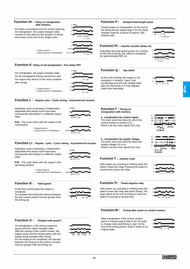
4
4/ii
Function P : Delayed fixed-length pulse
Timing begins on energisation. At the end ofthe timing period output relay R (or the load)changes state for a period of approx. 500milliseconds.
Function Pt : Impulse counter (delay on)
Calculates the total opening time of a contact.At the end of timing, the output is energisedfor approximately 500 ms.
Function Q : Star-delta"
At the end of timing, the output is notenergised. It remains "open" (notconducting) and will only change stateafter the fixed time of Ti has elapsed.Dwell time selectable
Function T : Timing onenergisation with memory
a - energisation by control signalThe timer sums the times for which thecontrol contact is closed (C1).Reset is by the reset signal (C2) only.
b - energisation by supply voltageThe timer sums the times for which thesupply voltage (U) is on.Reset is by the reset signal (C2) only
Function T : Impulse relay
After power-up, pressing or holding down the switch closes the relay. Pressing the switch a second time opens the relay.
Function Tt : Timed impulse relay
After power-up, pressing or holding down the switch closes the relay and starts timing. Therelay opens at the end of timing or when theswitch is pressed a second time.
Function W : Timing after pulse on control contact
After energisation, if the control contactopens it causes output relay R (or the load)to change state and timing to start. At theend of the timing period, relay R resets to itsoriginal state.
Function L : Repeat cylce - Cyclic timing - Asymmetrical recycler
Repetitive cycle comprising 2 independentadjustable time bases. Each time basecorresponds alternately to a different outputstate.
N.B. : The cycle starts with the output in therest position.
Function Li : Repeat cylce - Cyclic timing - Asymmetrical recycler
Repetitive cycle comprising 2 independentadjustable time bases. Each time basecorresponds alternately to a different outputstate.
N.B. : The cycle starts with the output in theoperating position.
Function N : "Safe-guard"
At the first control pulse the output isenergised.To complete the timing the interval betweenthe two control pulses must be greater thanthe timing set.
Function O : "Delayed safe-guard".
On energisation, a first timing sequenceoccurs and the output changes state.With the closing of the control contact, theoutput resets and the timing starts, with theoutput being activated after timing.For the timing to be completed, the intervalbetween the closing of two control contactsmust be greater than the timing set.
T1R
T2
U
T1R
U
T2
T
R
C
U
T T
U
RT P
P = 500 ms
TR
U
Ti
U
C
Rt1 t2 PT= t1+t2
TR
C
U
U
C
RT t
8 8 8
U
C
R
TR
C
U
T1R1/R2
T2
U
T1R1/R2
U
T2
1 relay
2 relays timed or 1 relay timed and 1 instantaneous
1 relay
2 relays timed or 1 relay timed and 1 instantaneous
Function Ht : Delay on energisation with memory
Provides a cumulative time for contact opening.On energisation, the output changes state,remains in that state for the duration of timing and resets at the end of the single cycle.
Function K: Delay on de-energisation - True delay OFF
On energisation, the output changes state.On de-energisation timing commences andthe output only returns to the reset conditionafter timing.
TR
U
t1R
C
U
t2T = t1+t2
t1R1/R2
C
U
t2
T = t1+t2R2 Inst.
1 relay
2 relays timed or 1 relay timed and 1 instantaneous
1 relay
2 relays timed or 1 relay timed and 1 instantaneous
TR2
U
R1

TIMERS TIMERS
Products and specifications subject to change without notice.Consult factory for application assistance.
204 Airline Drive, Suite 300, Coppell, Texas 75019 / Tel: (800) 677-5311 / FAX: (800) 677-3865 / www.crouzet-usa.com4-16
RTM SERIESDELAY ON MAKE TIMERUL listed CSA recognized
• Subminiature 21 x 27mm Enclosure
• Multi timing Range (0.55 to 100 hrs)
• Low Cost
• 4PDT Relay Output
• LED Power On Indicator
• LED Relay Indicator
SPECIFICATIONS:Input Power . . . . . . . . . . . . . . . . . . 230 VAC, 115 VAC, ±15%, 50/60HzPower consumption . . . . . . . . . . . 3 VA at 230 VAC
3 VA at 115 VACOutput Rating 4PDT VersionMaximum load 5 AmpMaximum switching voltage 100 m AmpMaximum power rating 240 VACElectrical life at 240 VAC 2 x 10⁵ operationsMechanical life 107 operationsSetting error . . . . . . . . . . . . . . . . . ±20%Repeat accuracy . . . . . . . . . . . . . . ±0.5%Reset time . . . . . . . . . . . . . . . . . . . 50 msec. after timing
100 msec. during timingDielectric strength . . . . . . . . . . . . . 2KV VAC between coil and contact
1000 VAC between contactsNoise Immunity . . . . . . . . . . . . . . . Consult FactoryOperating temperature . . . . . . . . . -20°C to +60°CWeight . . . . . . . . . . . . . . . . . . . . . . 50 gramsNote: When Time Base Selector is on “Inst.,” the ouput relays will turn oninstantaneously
WIRING DIAGRAM:
DIMENSIONS: (mm)
See “Accessories” section for PC Board and DIN-Rail sockets
0 T
Input Power S1
Relay
Delay on MakeFunction A:
R1 R213
9
5
1
˜(+)
10
6
2
11
7
3
14
12
8
4
(-)
RTM-4PDT
Input
21
R Un
3.5
27
59.5
65.5
0.55
21
27
Time Base Selector
5.5
2.8
31.2
ORDERING INFORMATION:Voltage Part NumberPart Number
Voltage12 VDC24 VDC24 VAC115 VAC230 VAC
4 PDT Version8889620188896202888962038889620688896207
4 PDT Version
RelayR1 R2
R3 R4

TIMERS TIMERS
4
Products and specifications subject to change without notice.Consult factory for application assistance.
204 Airline Drive, Suite 300, Coppell, Texas 75019 / Tel: (800) 677-5311 / FAX: (800) 677-3865 / www.crouzet-usa.com4-17
SPECIFICATIONS:Input . . . . . . . . . . . . . . . . . . . . . . . . 24 VAC/DC, 48 VAC/DC, 110 VAC
220 VAC, ±15%, 50/60 HzMaximum power consumption . . . 24 VAC: 1.5 VA 24 VDC: 0.8 W
48 VAC: 2 VA 24 VDC: 1.8 W110 VAC: 5 VA220 VAC: 11 VA
Output . . . . . . . . . . . . . . . . . . . . . . DPDTContact material . . . . . . . . . . . . . . AgCdOMaximum loading . . . . . . . . . . . . . 10 A AC resistive 1A DC inductiveMaximum switching voltage . . . . . 240 VAC 30 VDCMaximum power rating . . . . . . . . . 2400 VA 30 WMechanical life of relay . . . . . . . . . 30 x 104 operationsElectrical life of relay . . . . . . . . . . . 2 x 10⁵ at 2400 VAC resistive loadRepetition accuracy . . . . . . . . . . . ±0.5% at a constant ambientReset time . . . . . . . . . . . . . . . . . . . Function A: 50ms after timing
100 ms during timingOperating temperature . . . . . . . . . +14°F to +140°F -10°C to +60°CWeight . . . . . . . . . . . . . . . . . . . . . . 2.8 oz. (80g)
MOUNTINGN = Open P.C. Board
TIME RANGEB Range = 0.06 secs - 160 secs. H Range = 15 secs - 640 min.• 0.06 secs - 0.6 secs • 15 secs - 150 secs• 0.25 secs - 2.5 secs • 60 secs - 600 secs• 2 secs - 20 secs • 8 min - 80 min• 16 secs - 160 secs • 64 min - 640 min
SERIESAR2
NMOUNTING
AR2SERIES
BTIME RANGE
24 ADINPUT POWER
INPUT POWER24AD = 24 VAC/DC48AD = 48 VAC/DC
110A = 110 VAC220A = 220 VAC
WIRING DIAGRAM:
DIMENSIONS: inches (mm)
ORDERING INFORMATION:
Function A: When input power (S1) is applied, timing (T)begins. At the end of the preselected time (T1), the relayenergizes. The output relay is de-energized when power isremoved, this resetting the timer for another cycle.
T
Input Power S1
Relay0 t
Delay on MakeFunction A:
S1
SLIDESWITCH
˜(+)
1 2 3 4
˜(-)
POTENTIOMETER
(92) 3.62
(76.2) 3
(55) 2.15(38.1) 1.5
NAR2 SERIESDELAY ON MAKERELAY OUTPUTUL listed
The open PC board N Series timers are designedto the most demanding specifications according to VDE 0435 (tested to 2 KV isolation). Creep andstrike distances to VDE 0110 Group C 250 V.Designed to conveniently snap into 2-1/4˝ widesnaptrak.

TIMERS TIMERS
Products and specifications subject to change without notice.Consult factory for application assistance.
204 Airline Drive, Suite 300, Coppell, Texas 75019 / Tel: (800) 677-5311 / FAX: (800) 677-3865 / www.crouzet-usa.com4-34
GENERAL DETAILSOF TYPE Q TIMERSQ series timers are compact, low cost, precision devices designed to the most demandingspecifications. The small size, epoxy filled case is highly resistant against dust, vibrations,shock and humidity. Creep and strike distance according to VDE 0110 Group C 250V. Caseprotection IP66. Case material - Phenolic.
QAS SERIESDELAY ON MAKEELECTRONIC TIMERUL listed CSA recognized
SPECIFICATIONS:Input Power . . . . . . . . . . . . . . . . . 24 VAC/DC, 110 VAC/DC
220 VAC/DC ±15%, 50/60 HzOutput Rating . . . . . . . . . . . . . . . max.: 0.7 A at 20°C
min.: 10 mAVoltage drop after timing . . . . . . 3.5 VAC/DCRepetition accuracy . . . . . . . . . . ±0.5% at a constant ambientTemp rise derating . . . . . . . . . . . 5 mA / °CReset time SAS & SAS-D . . . . . . 25 ms after timing
50 ms during timingLeakage current during timing . . 5 mA maxPeak surge current . . . . . . . . . . . 20 A < 10 msPeak surge voltage . . . . . . . . . . . 1400 V, 10 µsTerminals . . . . . . . . . . . . . . . . . . . 1/4˝ (6.35mm) quick connectOperating temperature . . . . . . . . -22°F to +140°F (-30°C to +60°C)Weight . . . . . . . . . . . . . . . . . . . . . 1.9 oz. (55g)
MOUNTINGQ = Encapsulated
SERIESAS = fixed timeAS-D = remote potentiometerAS-P = internal potentiometer
TIME RANGEAS = Fixed .1 sec - 120 minAS-D = .1 sec - 60 min. 10:1 RatioAS-P = .1 sec - 10 sec
1-100 sec maintain 100:1 ratio
QMOUNTING
AS-DSERIES
100STIME RANGE
220 ADINPUT POWER
INPUT POWER24AD = 24 VAC/DC110AD = 110 VAC/DC220AD = 220 VAC/DC
WIRING DIAGRAM:
ORDERING INFORMATION: (25 pcs. minimum)P.S.: Specify maximum time for “D” and “P” version.
Function A: When input power is applied, timing (t) begins. At the end of the preselected time, the solid state SCR output turns on. The out-put turns off when the input power is removed, resetting the timer forthe next cycle.
Note: Available with internal potentiometer in AS-P Series
2.00(50.8mm)
2.00(50.8mm)
1.30(33.2 mm)
.75(19.05 mm)
250 DIA. MALE QUICK CONNECT TERMINALS(16.35 mm)
250(16.35 mm)
0 T
Input Power S1
Output
Delay on MakeFunction A:
˜+-
˜+-
1 3
LOAD
INPUT
˜+-
˜+-
1 3
LOAD
INPUT
470K
RT
QAS QAS-D
Peak Surge Current
Peak Surge Current vs Surge Current Duration
Surge Current Duration
100A
50A
20A15A10A
5A
2A
1A
10ms 20ms 50ms 100ms 200ms 500ms 1s 2s 5s

TIMERS TIMERS
4
Products and specifications subject to change without notice.Consult factory for application assistance.
204 Airline Drive, Suite 300, Coppell, Texas 75019 / Tel: (800) 677-5311 / FAX: (800) 677-3865 / www.crouzet-usa.com4-35
QBS SERIESSINGLE SHOT TIMER
QCS SERIESDELAY ON BREAK TIMERUL listed CSA recognized
• CMOS Technology
• Epoxy Encapsulated
• 2˝ x 2˝ Compact Size
• .250˝ Quick Connect Terminals
SPECIFICATIONS:Input . . . . . . . . . . . . . . . . . . . . . . . . 24 VAC, 48 VAC, 110 VAC
220 VAC, ±15%, 50/60 HzMaximum power consumption . . . 24 VAC: 0.2 VA
48 VAC: 0.3 VA110 VAC: 0.6 VA220 VAC: 1.2 VA
Output . . . . . . . . . . . . . . . . . . . . . . SCROutput Rating . . . . . . . . . . . . . . . . max.: 1A at 20°C
min.: 10 mAVoltage drop after timing . . . . . . . . 3.5 V max. ACRepetition accuracy . . . . . . . . . . . ±0.5% at a constant ambientTemp. rise derating . . . . . . . . . . . . 5 mA / °CReset time . . . . . . . . . . . . . . . . . . . 80 msMinimum contact closure . . . . . . . 100 ms during timingLeakage current during timing . . . 5 mA max.Peak surge current . . . . . . . . . . . . 20 A < 10 msPeak surge voltage . . . . . . . . . . . . 1400 V, 100 µsTerminals . . . . . . . . . . . . . . . . . . . . 1/4˝ (6.35) quick connectOperating temperature . . . . . . . . . -22°F to +140°F -30°C to +60°CWeight . . . . . . . . . . . . . . . . . . . . . . 1.9 oz. (55g)
The initiate switch should be isolated from the other circuits. Contact willoperate on the same supply as the timer and will have a max. load of 5 mA.
The remote potentiometer for the QCS-D and QBS-D should be 470 kΩ, 1/4 W.Use with shielded cable at a maximum length of 50 feet.
MOUNTINGQ = Encapsulated
TIME RANGECS/BS = Fixed timeCS-D = .06 sec. - 120 minBS-D = .06 sec. - 120 min. maintain 10:1 ratioB or CSP = .1 - 10 sec. or min
1 - 100 sec. or min. maintain 100:1 ratio
SERIESCS = Fixed timeBS = Fixed timeCS-D = Remote potentiometerBS-D = Remote potentiometerCS-P = Internal potentiometerBS-P = Internal potentiometer
QMOUNTING
CSSERIES
BTIME RANGE
110AINPUT POWER
INPUT POWER24A = 24 VAC48A = 48 VAC110A = 110 VAC220A = 220 VAC
WIRING DIAGRAM:
ORDERING INFORMATION:
NOTE: Available with internal potentiometer in B or CS-P Series.
T
InputPower S1
InitiateSwitch S2
RelayT
Single ShotFunction B:
Delay on BreakFunction C:
Function C: Input power (S1) is continuously supplied to the timer. Whenan external initiate switch (S2) is closed, the output relay is energized.Timing begins when the S2 switch opens. At the end of the delay time (T),the output is de-energized and the timer is ready for another cycle. Isolatethe initiate switch (S2) from other circuits.
Function B: Input power (S1) is continuously supplied to the timer. When an external initiate switch (S2) is closed, momentarily or maintained, the output relay is energized. At the end of the delay time (T), the output isde-energized. The timer is ready for another cycle. Isolate the initiateswitch (S2) from other circuits.
1 2 3
6 5 4
Load
Input
QCS-D QBS-D
R = 470KInitiateSwitch
S2
˜
˜1 2 3
6
Load
Input
QCS QBSInitiateSwitch
S2
˜
˜
DIMENSIONS See page 4-34

TIMERS TIMERS
Products and specifications subject to change without notice.Consult factory for application assistance.
204 Airline Drive, Suite 300, Coppell, Texas 75019 / Tel: (800) 677-5311 / FAX: (800) 677-3865 / www.crouzet-usa.com4-36
QDS SERIESREPEAT CYCLE
QHS SERIESINTERVAL ELECTRONIC TIMERUL listed CSA recognized
• Consistent Repeat Cycle
• Multiple Voltage
• 2˝ Square Cases
• Fixed and Variable Time Ranges
SPECIFICATIONS:Input . . . . . . . . . . . . . . . . . . . . . . . . 24 VAC, 48 VAC, 110 VAC
220 VAC, ±15%, 50/60 HzMaximum power consumption . . . 24 VAC: 0.2 VA
48 VAC: 0.3 VA110 VAC: 0.6 VA220 VAC: 1.2 VA
Output . . . . . . . . . . . . . . . . . . . . . . SCROutput Rating . . . . . . . . . . . . . . . . max.: 1 A at 20°C
min.: 10 mAVoltage drop after timing . . . . . . . . 3.5 VACRepetition accuracy . . . . . . . . . . . ±0.5% at a constant ambientTemp. rise derating . . . . . . . . . . . . 5 mA / °CReset time . . . . . . . . . . . . . . . . . . . 100 ms after timing
150 ms during timingMinimum contact closure . . . . . . . 100 ms during timingLeakage current during timing . . . 2 mA max.Peak surge current . . . . . . . . . . . . 20 A < 10 msPeak surge voltage . . . . . . . . . . . . 1400 V, 100 µsTerminals . . . . . . . . . . . . . . . . . . . . Faston 1/4˝ (6.35)Operating temperature . . . . . . . . . -22°F to +140°F -30°C to +60°CWeight . . . . . . . . . . . . . . . . . . . . . . 1.9 oz. (55g)
MOUNTINGQ = Encapsulated
TIME RANGEDS/HS = Fixed .1s - 120 min.
DS-D/HS-D = .1 sec - 120 min. maintaining 10:1 ratioDS-P/HS-P = .1-10 sec or min
1-100 sec. or min. maintain 100:1 ratio
SERIESDS = Fixed time
DS-D = Remote potentiometerHS = Fixed time
HS-D = Remote potentiometerDS-P = Internal potentiometerHS-P = Internal potentiometer
QMOUNTING
DSSERIES
10 minTIME RANGE
24AINPUT POWER
INPUT POWER24A = 24 VAC48A = 48 VAC110A = 110 VAC220A = 220 VAC
WIRING DIAGRAM:
ORDERING INFORMATION:
NOTE: Available with internal potentiometer in HS-P Series.
T
InputPower S1
Output0 t
T10 t
T2
RecyclingFunction D:
Interval TimerFunction H:
Function D: When input power (S1) is applied, the sold state outputturns on immediately for the time period specified. It then turns OFFfor that same time period and repeats continuously while power isapplied.
Function H: The solid state output turns on when the input power(S1) is applied. The output turns off at the end of time (T). The timeris reset when the input power is removed.
1 2 3
5 4
Load
Input
QHS-D QDS-D
RT
˜˜
470K
1 2 3
Load
Input
QHS QDS
˜˜
DIMENSIONS See page 4-34

TIMERS TIMERS
4
GENERAL DETAILSOF TYPE S TIMERSS series are compact, low cost, precision devices designed to the mostdemanding specifications. The small size, epoxy filled case is highly resistantagainst dust, vibrations, shock or humidity. Creep and strike distance accordingto VDE 0110 Group C 250V. Case protection IP66. Case material - Polymid.
SAS SERIESDELAY ON MAKETIMER WITH SOLIDSTATE OUTPUTUL listed CSA recognized
SPECIFICATIONS:Input Power . . . . . . . . . . . . . . . . . . 24 VAC/DC, 110 VAC/DC
220 VAC/DC, ±15%, 50/60 HzOutput Rating . . . . . . . . . . . . . . . . max.: 0.7 A at 20°C . . . . . . . . . . . . . . . . . . . . . . . . . . . . min.: 10 mA
Repetition accuracy . . . . . . . . . . . ±0.5% at a constant ambientTemp rise derating . . . . . . . . . . . . 5 mA / °CReset time SAS & SAS-D . . . . . . . 25 ms after timing
100 ms during timingSAS-P . . . . . . . . . . . . . 100 ms during timing
Leakage current during timing . . . 5 mA maxPeak surge current . . . . . . . . . . . . 20 A < 10 msPeak surge voltage . . . . . . . . . . . . 1400 V, 10 µsTerminals . . . . . . . . . . . . . . . . . . . . 1/4˝ (6.35mm) quick connectOpertating temperature . . . . . . . . . -22°F to +140°F (-30°C to +60°C)Weight . . . . . . . . . . . . . . . . . . . . . . 1.9 oz. (55g)NOTE: The part number for the remote potentiometer is CD1.
WIRING DIAGRAM:
ORDERING INFORMATION: (25 pcs. minimum)
Function A: When input power is applied, timing (t) begins. At the end of the preselected time, the solid state SCR output turns on. The out-put turns off when the input power is removed, resetting the timer forthe next cycle.
0 T
Input Power S1
Output
Delay on MakeFunction A:
Peak Surge Current
Peak Surge Current vs Surge Current Duration
Surge Current Duration
100A
50A
20A15A10A
5A
2A
1A
10ms 20ms 50ms 100ms 200ms 500ms 1s 2s 5s
1.96(50)
0.8 0.77(45)
0.47(12)
2.76(70)
2.46(62.5)
0.16(42)
0.69(17.5)6.35
2.36(60)
S1
A1 A2
SAS
LOAD
S1
A1 A2
S1
A1 A2
SAS-D SAS-P
Z1 Z2
LOAD LOAD
470K
POTENTIOMETER
˜+-
˜+-
MOUNTINGS =Encapsulated requiring
DIN-Rail, Panel Adapteror use Base MountingHoles
SMOUNTING
AS-DSERIES
100STIME RANGE
220 ADINPUT POWER
SERIESAS = standard relayAS-D = remote potentiometerAS-P = internal potentiometer
TIME RANGEAS = Fixed .1 sec - 1 minAS-D = .1 sec - 60 minEx: = 10-100 sec maintain 10:1 ratioAS-P = .1 sec - 10 sec
1-100 sec maintain 100:1 ratio
INPUT POWER24AD = 24 VAC/DC110AD = 110 VAC/DC220AD = 220 VAC/DC
Products and specifications subject to change without notice.Consult factory for application assistance.
204 Airline Drive, Suite 300, Coppell, Texas 75019 / Tel: (800) 677-5311 / FAX: (800) 677-3865 / www.crouzet-usa.com4-31

TIMERS TIMERS
SDS SERIESREPEAT CYCLE TIMERUL listed CSA recognized
• Shock Resistant
• SCR Solid State Output
• Optional Remote Potentiometer
• DIN-Rail or Base Mounting
SPECIFICATIONS:Input . . . . . . . . . . . . . . . . . . . . . . 24 VAC, 48 VAC, 110 VAC
220 VAC, ±15%, 50/60 HzMaximum power consumption . . 24 VAC: 0.2 VA
48 VAC: 0.3 VA110 VAC: 0.6 VA220 VAC: 1.2 VA
Output . . . . . . . . . . . . . . . . . . . . . SCROutput Rating . . . . . . . . . . . . . . . max.: 0.7 A at 20°C
min.: 10 mARepetition accuracy . . . . . . . . . . ±0.5% at a constant ambientTemp. rise derating . . . . . . . . . . . 5 mA / °CReset time . . . . . . . . . . . . . . . . . . 100 ms after timing
150 ms during timingLeakage current during timing . . 2 mA max.Peak surge current . . . . . . . . . . . 20 A < 10msPeak surge voltage . . . . . . . . . . . 1400 V, 100 µsTerminals . . . . . . . . . . . . . . . . . . . Faston 1/4˝ (6.35mm)Operating temperature . . . . . . . . -22°F to +140°F -30°C to +60°CWeight . . . . . . . . . . . . . . . . . . . . . 1.9 oz. (55g)
Note: Part # for the remote potentiometer is CD1.
WIRING DIAGRAM:
ORDERING INFORMATION: (25 pcs. minimum)P.S.: Specify maximum time for “D” and “P” versions.
When input power S1 is applied, the solid state output turns onimmediately for the timer period specified. It then turns OFF for thatsame time period and repeats continuously while power is applied.Input Power S1
OutputT T
0t
Recycling
SDS SDSD SDSP
S1 S1 S1
POTENTIOMETER
470 K
A2 18 A1A2 18 A1 A2 18 A1 Z1 Z2
LOAD LOAD LOAD
MOUNTINGS = Encapsulated, requiring
DIN-Rail, Panel Adapter oruse Base Mounting Holes
TIME RANGEDS = Fixed .1s. - 120 minDS-D = .1 sec. - 120 min.
Maintain 10:1 ratioDS-P = 1 -10 sec. or min., 10 - 100 sec. or min.
Maintain 100:1 ratio
SERIESDS = Fixed timeDS-D = remote potentiometerDS-P = internal potentiometer
SMOUNTING
DSSERIES
10 minTIME RANGE
24INPUT POWER
INPUT POWER24A = 24 VAC48A= 48 VAC110A = 110 VAC220A = 220 VAC
DIMENSIONS See page 4-31
Products and specifications subject to change without notice.Consult factory for application assistance.
204 Airline Drive, Suite 300, Coppell, Texas 75019 / Tel: (800) 677-5311 / FAX: (800) 677-3865 / www.crouzet-usa.com4-32

TIMERS TIMERS
4
SHS SERIESINTERVAL TIMER WITHSOLID STATE OUTPUTUL listed CSA recognized
• Epoxy Encapsulated
• DIN-Rail or Base Mounting
• Internal or External Time Set
• Fixed Time
SPECIFICATIONS:Input . . . . . . . . . . . . . . . . . . . . . . 24 VAC, 48 VAC, 110 VAC
220 VAC, ±15%, 50/60 HzMaximum power consumption . . 24 VAC: 0.2 VA
48 VAC: 0.3 VA110 VAC: 0.6 VA220 VAC: 1.2 VA
Output . . . . . . . . . . . . . . . . . . . . . SCROutput Rating . . . . . . . . . . . . . . . max.: 0.7 A at 20°C
min.: 10 mARepetition accuracy . . . . . . . . . . ±0.5% at a constant ambientTemp. rise derating . . . . . . . . . . . 5 mA / °CReset time . . . . . . . . . . . . . . . . . . 100 ms after timing
150 ms during timingLeakage current during timing . 2 mA max.Peak surge current . . . . . . . . . . . 20 A < 10 msPeak surge voltage . . . . . . . . . . . 1400 V, 100 µsTerminals . . . . . . . . . . . . . . . . . . Faston 1/4˝ (6.35mm)Operating temperature . . . . . . . . -22°F to +140°F -30°C to +60°CWeight . . . . . . . . . . . . . . . . . . . . . 1.9 oz. (55g)
Note: Part # for the remote potentiometer is CD1.
WIRING DIAGRAM:
ORDERING INFORMATION: (25 pcs. minimum)P.S.: Specify maximum time for “D” and “P” versions.
The solid state output turns on when the input power (S1) isapplied. The output turns off at the end of time (T). The timer isreset when the input power is removed.
Note: Available with internal potentiometer in HS-P Series.
Function H:Internal Timer
Input Power S1
OutputT t0
SHS SHS-D SHS-P
S1 S1 S1
POTENTIOMETER
470 K
A2 18 A1A2 18 A1 A2 18 A1 Z1 Z2
LOAD LOAD LOAD
MOUNTINGS = Encapsulated, requiring
DIN-Rail, Panel Adapter oruse Base Mounting Holes
TIME RANGEHS = Fixed .1s. - 120 minHS-D = .1 sec. - 120 min. Maintain 10:1 ratioHS-P = 1 -10 sec. or min., 10 - 100 sec. or min.
Maintain 100:1 ratio
SERIESHS = Fixed timeHS-D = remote potentiometerHS-P = internal potentiometer
SMOUNTING
HS-DSERIES
300STIME RANGE
220AINPUT POWER
INPUT POWER24A = 24 VAC48A = 48 VAC110A = 110 VAC220A = 220 VAC
DIMENSIONS See page 4-31
Products and specifications subject to change without notice.Consult factory for application assistance.
204 Airline Drive, Suite 300, Coppell, Texas 75019 / Tel: (800) 677-5311 / FAX: (800) 677-3865 / www.crouzet-usa.com4-33

TIMERS TIMERS
4
Products and specifications subject to change without notice.Consult factory for application assistance.
204 Airline Drive, Suite 300, Coppell, Texas 75019 / Tel: (800) 677-5311 / FAX: (800) 677-3865 / www.crouzet-usa.com4-37
88 256.4 and 88 256.5SERIESMANUALLY SETINTERVAL TIMERUL listed CSA recognized
• Standard Motor
• Standard Switches
• Easy to use and troubleshoot
SPECIFICATIONS:Standard Voltage . . . . . . . . . . 115 V - 60 HzInput Power . . . . . . . . . . . . . . 3.5 WattsOther voltages on request
Motor 82 344 (Crouzet)Output Circuit . . . . . . . . . . . . . Switch 83 160.0 (Crouzet)Contact material . . . . . . . . . . . AgCdORating . . . . . . . . . . . . . . . . . . . 8 Amp, 125/250 ACConnections . . . . . . . . . . . . . . 1/4˝ spade terminalsAmbient Limits . . . . . . . . . . . . 23°F to 158.0°F
(-5°C to +70°C)UL components recognized
NOTE: If motor connected to constant supply, timer becomes a recycle timer.
WIRING DIAGRAM:
DIMENSIONS: inches (mm)
DESCRIPTION:An adjustable knob with a graduated dial is mounted on the motor output shaft. A friction clutch allows it to be rotated manually.
In the case of the Single Pole version, the molded cam is set to operatethe switch when the zero position is reached.
In the case of the Double Pole version, the second switch (No. 2)changes over after the first switch (No. 1). The second switch (No. 2)controls the motor.
T = desired time.
Dephasing is equal to 3% of total max. time range on switch #2.
Actuation
Switch1
Switch2
W
R
W
R
W = work R = rest D = dephasing T = time
T D
End TimeSwitch 1(Device)
End TimeSwitch 2(Motor)
1 2
NO
NCC
minc
Single pole: 2.83 (72)Double pole: 3.29 (83.5)
.787 (20)
dia
.236
(6)
.197
(5)
.394 (10)
.561
(14
.25)
.561
(14
.25)
2.16 (55)
2 fixing holes*
.118 (M3)
1 (2
5.5)
31.5
(80
)
* (2) screws supplied
.629(16)
2.36
(61
)
.118(3)

TIMERS TIMERS
Products and specifications subject to change without notice.Consult factory for application assistance.
204 Airline Drive, Suite 300, Coppell, Texas 75019 / Tel: (800) 677-5311 / FAX: (800) 677-3865 / www.crouzet-usa.com4-38
SERIES 88 256.4 AND 88 256.5MANUALLY SET INTERVAL TIMERS
For other Time & Voltage requirements contact factory.
IMPORTANT NOTE:The maximum time setting is equal to 17/18 of the maximum dial range.
ORDERING INFORMATION:
Specify Part numberExample: 88 256 4.3 HR
PART NUMBER NUMBER MODEL MAXIMUM ACCURACY DEPHASING VOLTAGEOF CAMS TIME RANGE OF SETTING+ OF SWITCHES
88 256 455 1 60 sec. 56 sec. 2.5 sec – 115 VAC - 60 hz
88 256 456 1 30 min. 28 min. 1 min. – 115 VAC - 60 hz
88 256 457 1 1 hr. 56 min. 2.5 min. – 115 VAC - 60 hz
88 256 562 2 60 sec. 56 sec. 2.5 2 sec. 115 VAC - 60 hz
88 256 563 2 5 min. 4 min. 40 sec. 15 sec. 9 sec. 115 VAC - 60 hz
88 256 564 2 15 min. 14 min. 30 sec. 27 sec. 115 VAC - 60 hz
88 256 565 2 1 hr. 56 min. 2.5 min. 1 min. 48 sec. 115 VAC - 60 hz
88 256 4.30 HR 1 30 hr. 28 hr. 1 hr. – 115 VAC - 60 hz
88 256 4.30 SEC 1 30 sec. 28 sec. 1 sec. – 115 VAC - 60 hz
88 256 4.5 HR 1 5 hr. 4 hr. 43 min. 15 min. – 220 VAC - 60 hz
88 256 4.5 MIN 1 5 min. 4 min. 40 sec. 15 sec. – 115 VAC - 60 hz
88 256 5.15 SEC 2 15 sec. 14 sec. .5 sec. .45 sec. 115 VAC - 60 hz
88 256 5.30 SEC 2 30 sec. 28 sec. 1 sec. .9 sec. 115 VAC - 60 hz

TIMERS TIMERS
Products and specifications subject to change without notice.Consult factory for application assistance.
204 Airline Drive, Suite 300, Coppell, Texas 75019 / Tel: (800) 677-5311 / FAX: (800) 677-3865 / www.crouzet-usa.com4-40
STANDARD CAMS FOR SINGLE ON/OFF OPERATION PERCYCLE:Cams are adjusted by using red plastic key supplied. Each cam con-sists of two sections, one red half and one grey half. The grey section isnormally adjusted for “start” and the red sections for “stop.” Each camhas a notch which will match the tab on the red adjusting key. With thekey positioned so the “start” side is facing the knob, the grey cam sec-tion can be adjusted by inserting the tab of the key into the notch in thecam while turning the knob. Reversing the key so the “stop” side facesthe knob, the red cam can be adjusted.STEP 1. Insert Cam Adjusting Key into No. 1 cam (grey section) havingthe word “start” on tool facing adjusted knob and turn knob until thedegree reading matches the first transfer point on your time chart forthat cam.STEP 2. Insert Cam Adjusting Key into No. 1 (red section) having theword “stop” on tool now facing cam adjusted knob and turn knob untilthe degree reading matches the next transfer point on your time chartfor that same cam. This complete setting of No.1 cam.STEP 3. Repeat steps 1 and 2 for each additional circuit of your camtimer.note: All switches have single pole, double throw circuitry. On each circuit where the load should be energized for less than 180° of camshaft rotation, use the NC switch terminal. On each circuit where theload should be energized for more that 180° of cam shaft rotation, usethe NO switch terminal.
SPECIFICATIONS:
88 645 SERIESCAM TIMERSUL listed CSA recognized
88 645 Series is specifically adapted for applications requiring 1 to 22 circuits. The switches are mounted on both sides of frame to give minimum overall length.Precision SPDT switches rated at 6 Amps, 1/3 H.P., 125/250 V AC are standard.Switches are individually removable. Adjustable cams, simple and quick setting.Adjustable cam key comes as standard.
GENERALVoltage . . . . . . . . . . . . . . . . . . . . . . 220 VAC, 115 VAC, 24 VAC (+10-15%), 50-60 HzInput Power88 645 (Crouzet motor 82 334) . . . . 2.3 WOperating Temperature. . . . . . . . . . -5°C to +60°C (23°F to +140°F)Storage Temperature . . . . . . . . . . . -40°C to +80°C (-40°F to +178°F)Duty Cycle . . . . . . . . . . . . . . . . . . . 100%Circuitry . . . . . . . . . . . . . . . . . . . . . SPDTOutput Switches (Crouzet 83 160 080) 6 A, 1/3 H.P., 125/250Wiring Connections
Gear Motor . . . . . . . . . . . . . . . . 1/4˝ spade terminal blockSwitches . . . . . . . . . . . . . . . . . . 1/4˝ spade terminals
Direction . . . . . . . . . . . . . . . . . . . . . CW direction is standardCAMSMinimum Notch or Pulse
(Electrical) . . . . . . . . . . . . . . . . . 12° (1/20 of a cycle)Rise
(Electrical) . . . . . . . . . . . . . . . . . 12° (1/20 of a cycle)Maximum Cam Speed. . . . . . . . . . . 30 RPMSetting Accuracy . . . . . . . . . . . . . . 1°Repeat Accuracy
Adjustable and ProgrammableCam . . . . . . . . . . . . . . . . . . . . . . +1° (±.25% of cycle time)Cut Cams. . . . . . . . . . . . . . . . . . ±.5% (±.125% of cycle time)
Cam ConstructionAdjustable . . . . . . . . . . . . . . . . . split type - made of delrin
Type Cams Circuits A B WeightAvail. inch (mm) oz (g)
88 645 0 7 1 to 7 3.23 ( 82) 5.12 (130) 19.40 ( 550)88 645 2 12 8 to 12 4.57 (116) 6.46 (164) 26.45 ( 750)88 645 4 17 13 to 17 5.83 (148) 7.72 (196) 31.75 ( 900)88 645 6 22 18 to 22 7.09 (180) 8.98 (228) 35.27 (1000)
OPTIONAL:P: Programmable Cams: For multiple on/off operations per cycle see page 3-42 for details.C: Cut Cams: For multiple or non-tamperable operations per cycle, consult factory with time charts for cams.
1.97 (50)2.60 (66)4.13 (105)
1.97
(50
)3.
11 (
79)
.413
(10.
5)
.59A
B
.17(4.5) (15)
2.09
(53
)
CP
DIMENSIONS: inches (mm)88 645 SERIES
ORDERING INFORMATION: SPEED/CYCLE TIMESERIES NO. OF CAMS TYPE OF CAM S=sec - M=min. - H=Hr ELECTRICAL. . .
SERIES88 645
NO. OF CAMS007 = 7 cam212 = 12 cam417 = 17 cam622 = 22 cam
TYPE OF CAMS= Standard camP= Programmable camC= Cut cam
SPEED/CYCLE TIMESelect one of these
2S 6S 15S 60S 4M 30M 4H3S 10S 20S 2M 10M 1H 12H4S 12S 30S 3M 15M 2H 24H
ELECTRICALAS = 115 VAC - 60 Hz ES = 220 VAC - 50 HzAH = 220 VAC - 60 Hz EL = 24 VAC - 50 HzAL = 24 VAC - 60 Hz CS = 110 VAC - 50 Hz
EXAMPLE: 88645002.P.10S.AS ie: 88 645 cam timer with 2 programmable cams, 10 second speed/cycle time, and 115 VAC - 60hz.

TIMERS TIMERS
4
Products and specifications subject to change without notice.Consult factory for application assistance.
204 Airline Drive, Suite 300, Coppell, Texas 75019 / Tel: (800) 677-5311 / FAX: (800) 677-3865 / www.crouzet-usa.com4-41
A cam timer is a simple timing device comprised of a frame which holds a series of cams on a shaft.The shaft is driven by a motor with a gear train that is set to rotate 360˚ over a certain time period.During this time period the cams actuate snap-acting SPDT (Single Pole Double Throw) switches. Theswitches can be wired to be either NC (normally Closed) or NO (Normally Open) so that when the indi-vidual cam actuates the individual switch, its output changes from Open to Closed. This change willhappen once and go back to the rest position once in 360˚ with the standard cam. Maximum differentialper standard cam is 180˚.If multiple tripping of the switch is required, the cam must be changed to either a programmable cam or a custom cut-cam (in large quantities). With the programmable cam, Programmable Cam Pins mustalso be used and plugged-in at the required 6˚ intervals to create the desired effect.
Standardcam
Programmablecam with pins
Custom cut-cam
NOTE: Replacement redcam adjustment toolfor 88 645 and 88646 with standardcams: Part Number79 221 702
NOTE: Programmable cams can be combined with standard cams for the most economical results ofa required pattern by the user. See opposite page for more detail.
30˚30˚
30˚30˚
180˚180˚ 230˚230˚
180˚180˚170˚170˚54˚54˚42˚42˚ 250˚250˚240˚240˚ 280˚280˚
300˚300˚
360˚360˚0˚0˚
5050secsec
3030secsec
5secsec
T= 0T= 0 6060secsec
cycle=1 mincycle=1 min
TR
P1P1
P2P2
circ
uits
circ
uits
P3P3270˚270˚
EXAMPLE:
PROGRAMMING A CAM TIMER:It is best to create a time chart as shown. Use “T”as the trip-point and “R” as rest for each cam (P1,P2, P3, etc.) and draw throw/off pattern for eachmovement of the switch. This will make the finaladjustment very easy.
STANDARD CYCLE TIMES:TIME MOTOR SPEED TIME MOTOR SPEED2 sec . . . . . . . . . 30 RPM 1 min . . . . . . . 1 RPM3 sec . . . . . . . . . 20 RPM 2 min . . . . . . . . 1/2 RPM4 sec . . . . . . . . . 15 RPM 3 min . . . . . . . . 1/3 RPM6 sec . . . . . . . . . 10 RPM 4 min . . . . . . . . 1/4 RPM10 sec. . . . . . . . . 6 RPM 10 min . . . . . . .1/10 RPM12 sec . . . . . . . . 5 RPM 12 min . . . . . . .1/12 RPM15 sec . . . . . . . . 4 RPM 15 min . . . . . . .1/15 RPM20 sec . . . . . . . . 3 RPM 24 min . . . . . . .1/24 RPM30 sec . . . . . . . . 2 RPM 30 min . . . . . . .1/30 RPM60 sec . . . . . . . . 1 RPM

TIMERS TIMERS
Products and specifications subject to change without notice.Consult factory for application assistance.
204 Airline Drive, Suite 300, Coppell, Texas 75019 / Tel: (800) 677-5311 / FAX: (800) 677-3865 / www.crouzet-usa.com4-42
PROGRAMMABLE CAMS(for 88 645 & 88 646)INSTALLATION & INFORMATIONDisconnect timer from power sources (motor and switches) beforeinstalling programmable cams.
DESCRIPTION:CROUZET programmable cams should be used whenever multipleactuations are required from the same cam during one timing cycle. Anynumber of adjustable cams can be replaced with programmable cams.
INSTALLATION:It is suggested that the programmable cams be installed in timer beforethe programming pins are installed on the cam. To install cam(s), refer toinstructions for your particular model.
MODEL 88 645 SERIES:1. Remove snap ring and slide knob from cam shaft.2. Remove the two screws from gray end bracket and slide from cam
shaft. Note correct position before removing for reassembly.3. Loosen two screws on clutch assembly (opposite knob end) and
slide shaft assembly free.NOTE: On some models it may be necessary to run motor to allowaccess to screws. Position screws for easy access.
4. The adjustable cam(s) can now be removed by sliding them towardknob end of cam shaft.
5. Replace the adjustable cam(s) with programmable cam(s) makingsure the total number of adjustable and programmable cams isequal to original number of cams.
NOTE: When replacing adjustable cams, be sure red cam half is facingknob end of cam shaft.
6. There should not be any space between the cams and the firstcam should be against the shoulder on cam shaft.
7. Replace gray end bracket on cam shaft noting it is facing samedirection as when removed.
8. Replace knob and snap ring on shaft making sure snap ring issquare to and against knob. Shaft should rotate freely in bracket; ifnot, move snap ring away from knob slightly.
9. Replace entire assembly into cam timer with clutch assembly onmotor shaft and aligning holes in end bracket with mounting holes.Replace the two end bracket screws and tighten. Tighten clutchassembly screws.
79 222 640 Programmable Cam (1 piece)79 222 641 Programmable Cam Pins (1 bag)
1 bag = 30 pieces total10-Rise/Fall pins20 intermediate pins
MODEL 88 6451. Remove snap on protective cover.2. Loosen hex nut in center of knob and slide cover knob from
shaft.3. Remove the four screws securing the end bracket to timer
frame and remove end bracket.4. Loosen two screws on clutch assembly (end opposet knob)
and slide cam shaft assembly free.NOTE: On some timers it may be necessary to run motor to posi-
tion screws for easy access.5. Remove snap ring (knob end).6. The adjustable cams can now be removed by sliding them
toward the knob end of the cam shaft.7. Replace the adjustable cam (s) with programmable cam(s)
making sure total number of adjustable and programmablecams is equal to the original number of cams.
NOTE: When replacing adjustable cam, make sure red cam halfis facing knob end of cam shaft.8. There should not be any space between the cams and the
first cam should be against the shoulder on cam shaft.9. Replace snap ring on cam shaft making sure it is square and
against the last cam.10. Replace cam shaft assembly in timer so clutch assembly is
on motor shaft.11. Replace end bracket and secure with four screws.12. Tighten screws on clutch assembly.13. Replace knob and tighten hex nut.
PROGRAMMING CAMSEach slot on the programmable cam is 6° apart. Any operationrequires a minimum of one “rise” and one “fall” program pin; there-fore, the minimum pulse that can be obtained in 12° or 1/30 of thecycle time. (Cycle time being time for one complete revolution oftimer.) It is suggested a timing chart be made for each cam to makeprogramming easier. The chart should be from 0° to 360°. Indicate onthe chart each “on” and “off” point. Since the programmable cam hasslots ever 6°, the “on” and “off” degree points must be divisible by 6.
The following sample program illustrates a circuit with three pulsesper cycle.
When pins are insert on programmable cam, they are inserted from top of timer which will put the pins 180° from the actual switchingpoint. To compensate for this, you simply add 180° to each of youractuation points.
IMPORTANT: A “rise” and “fall” pin must always be used at thebeginning and end of actuation. Therefore, the minimum pulse will be12° or 1/30 of total time cycle. For ever intermediate pin used, thetime of the pulse will be increased by 6 or 1/60 of time cycle.
In example shown, first pulse will require 1 rise, 1 fall, 2 flat top pins.NOTE: Rise and fall pins are the same pins, the direction in whichthey are inserted determines whether it is a “rise” or “fall.”
When programmable cams are complete, the adjustable cams maybe adjusted in standard manner.
0°00° 54° 162° 180° 240° 282° 360°(210°) (234°) (342°)(360°) (60°) (102°)

TIMERS TIMERS
4
Products and specifications subject to change without notice.Consult factory for application assistance.
204 Airline Drive, Suite 300, Coppell, Texas 75019 / Tel: (800) 677-5311 / FAX: (800) 677-3865 / www.crouzet-usa.com4-39
SPECIFICATIONS:GENERALVoltage . . . . . . . . . . . . . . . . . . . . . . . . . 220 VAC, 115 VAC, 24 VAC, (+10 -15%) . . . . . . . . . . . . . . . . . . . . . . . . . . . . . . . 50-60 Hz
Input Power88 646 (Crouzet motor 82 344) . . . . . . . 2.6 WOperating Temperature . . . . . . . . . . . . -5°C +60°C (23°F +140°F)Storage Temperature . . . . . . . . . . . . . . -40°C +80°C (-40°F +178°F)Duty Cycle . . . . . . . . . . . . . . . . . . . . . . 100%Circuitry . . . . . . . . . . . . . . . . . . . . . . . . SPDTOutput Switches (Crouzet 83 160 080) 6 A, 1/3 H.P., 125/250Wiring Connections
Gear Motors . . . . . . . . . . . . . . . . . . . 1/4˝ spade terminal blockGear Motors . . . . . . . . . . . . . . . . . . . 1/4˝ spade terminal block
Direction . . . . . . . . . . . . . . . . . . . . . . . . CW direction is standard
88 646 SERIESCAM TIMERSUL listed CSA recognized
88 646 SERIES is specifically adapted for applications requiring 2 to 4 circuits. The switches are mounted on both sides of frame to give minimum overall length.Precision SPDT switches rated at 6 Amps, 1/3 H.P., 125/250V AC. are standard.Switches are individually removable. Adjustable cams are simple and quick setting.Adjustable cam key comes as standard.
STANDARD CAMS FOR SINGLE ON/OFF OPERATION PER CYCLE:Cams are adjusted by using red plastic key supplied. Each cam consists oftwo sections, one red half and one grey half. The grey section is normallyadjusted for “START” and the red section for “STOP.” Each cam has a notchwhich will match the tab on the adjusting key. With the key positioned so the“START” side is facing the knob, the grey cam section can be adjusted byinserting the tab of the key into the notch in the cam while turning the knob.Reversing the key so the “STOP” side faces the knob, the red cam can beadjusted.STEP 1. Insert Cam Adjusting Key into No. 1 cam (grey section) having theword “START” on tool facing adjusted knob and turn knob until the degreereading matches the first transfer point on your time chart for that cam.STEP 2. Insert Cam Adjusting Key into No. 1 (red section) having the word“STOP” on tool now facing cam adjusting knob and turn knob until thedegree reading matches the next transfer point on your time chart for thatsame cam. This completes setting of No. 1 cam.STEP 3. Repeat steps 1 and 2 for each additional circuit of your cam timer.NOTE: All switches have single pole, double throw circuitry. On each circuitwhere the load should be energized for less than 180° of cam shaft rotation,use the NO switch terminal.
SERIES88 646
SPEED/CYCLE TIMESelect one of these:
2S 6S 15S 60S 4M 30M 4H3S 10S 20S 2M 10M 1H 12H4S 12S 30S 3M 15M 2H 24H
NO. OF CAMS002 = 2 cam204 = 4 cam
SERIES TYPE OF CAM SPEED/CYCLE TIMES=s - M=min. - H=Hr
ELECTRICAL
ORDERING INFORMATION:
Type Cams Circuits A B Weightinch (mm) inch (mm) oz (g)
88 646 0 2 2 3.74 ( 95) 3.15 (80) 8.18 (250)88 646 2 4 4 4.25 (108) 3.66 (93) 10.58 (300)88 646 series mounted by clipping onto an INTERNATIONAL DIN-RAIL, or by two screws fastened by built in ears.
DIMENSIONS: inches (mm)88 646 SERIES
OPTIONAL:P: Programmable Cams: For multiple on/off operations per cycle see page 3-42 for details.C: Cut Cams: For multiple or non-tamperable operations per cycle, consult factory with time charts for cams.
NO. OF CAMS
TYPE OF CAMS=Standard camP=Programmable camC=Cut cam
ELECTRICALAS =115 VAC - 60hz ES =220 VAC - 50hzAH =220 VAC - 60hz EL =24 VAC - 50hzAL = 24 VAC - 60hz CS =110 VAC - 50hz
EXAMPLE: 88646002.S.6S.AS ie: 88 646 cam timer with 2 standard cams, 6 second cycle time, and 115 VAC - 60hz
P C
.69(17.5)
4.25 (108)
.55(14)
3.38
(86)
.69(17.5)
.30(7.5)
2.95 (75)
1.73 (44)
3.94 (100)
A
1.77
(45)
2.48
(63)
.59
(15)
B
...
CAMSMinimum Notch or Pulse
(Electrical) . . . . . . . . . . . . . . . . . . . . . . . 12° (1/20 of cycle)Rise
Electrical . . . . . . . . . . . . . . . . . . . . . . . . 12° (1/20 of cycle)Maximum Cam Speed . . . . . . . . . . . . . . . . 30 RPMSetting Accuracy . . . . . . . . . . . . . . . . . . . 1°Repeat Accuracy
Adjustable and ProgrammableCams . . . . . . . . . . . . . . . . . . . . . . . . . . . +1° (+.25% of cycle time)Cut Cams . . . . . . . . . . . . . . . . . . . . . . . . +0.5% (+ .125% of cycle . . . . . . . . . . . . . . . . . . . . . . . . . . . . . . . . time)
Cam ConstructionAdjustable . . . . . . . . . . . . . . . . . . . . . . . split type - made of delrin

TIMERS TIMERS
4
Products and specifications subject to change without notice.Consult factory for application assistance.
204 Airline Drive, Suite 300, Coppell, Texas 75019 / Tel: (800) 677-5311 / FAX: (800) 677-3865 / www.crouzet-usa.com4-41
A cam timer is a simple timing device comprised of a frame which holds a series of cams on a shaft.The shaft is driven by a motor with a gear train that is set to rotate 360˚ over a certain time period.During this time period the cams actuate snap-acting SPDT (Single Pole Double Throw) switches. Theswitches can be wired to be either NC (normally Closed) or NO (Normally Open) so that when the indi-vidual cam actuates the individual switch, its output changes from Open to Closed. This change willhappen once and go back to the rest position once in 360˚ with the standard cam. Maximum differentialper standard cam is 180˚.If multiple tripping of the switch is required, the cam must be changed to either a programmable cam or a custom cut-cam (in large quantities). With the programmable cam, Programmable Cam Pins mustalso be used and plugged-in at the required 6˚ intervals to create the desired effect.
Standardcam
Programmablecam with pins
Custom cut-cam
NOTE: Replacement redcam adjustment toolfor 88 645 and 88646 with standardcams: Part Number79 221 702
NOTE: Programmable cams can be combined with standard cams for the most economical results ofa required pattern by the user. See opposite page for more detail.
30˚30˚
30˚30˚
180˚180˚ 230˚230˚
180˚180˚170˚170˚54˚54˚42˚42˚ 250˚250˚240˚240˚ 280˚280˚
300˚300˚
360˚360˚0˚0˚
5050secsec
3030secsec
5secsec
T= 0T= 0 6060secsec
cycle=1 mincycle=1 min
TR
P1P1
P2P2
circ
uits
circ
uits
P3P3270˚270˚
EXAMPLE:
PROGRAMMING A CAM TIMER:It is best to create a time chart as shown. Use “T”as the trip-point and “R” as rest for each cam (P1,P2, P3, etc.) and draw throw/off pattern for eachmovement of the switch. This will make the finaladjustment very easy.
STANDARD CYCLE TIMES:TIME MOTOR SPEED TIME MOTOR SPEED2 sec . . . . . . . . . 30 RPM 1 min . . . . . . . 1 RPM3 sec . . . . . . . . . 20 RPM 2 min . . . . . . . . 1/2 RPM4 sec . . . . . . . . . 15 RPM 3 min . . . . . . . . 1/3 RPM6 sec . . . . . . . . . 10 RPM 4 min . . . . . . . . 1/4 RPM10 sec. . . . . . . . . 6 RPM 10 min . . . . . . .1/10 RPM12 sec . . . . . . . . 5 RPM 12 min . . . . . . .1/12 RPM15 sec . . . . . . . . 4 RPM 15 min . . . . . . .1/15 RPM20 sec . . . . . . . . 3 RPM 24 min . . . . . . .1/24 RPM30 sec . . . . . . . . 2 RPM 30 min . . . . . . .1/30 RPM60 sec . . . . . . . . 1 RPM

TIMERS TIMERS
Products and specifications subject to change without notice.Consult factory for application assistance.
204 Airline Drive, Suite 300, Coppell, Texas 75019 / Tel: (800) 677-5311 / FAX: (800) 677-3865 / www.crouzet-usa.com4-42
PROGRAMMABLE CAMS(for 88 645 & 88 646)INSTALLATION & INFORMATIONDisconnect timer from power sources (motor and switches) beforeinstalling programmable cams.
DESCRIPTION:CROUZET programmable cams should be used whenever multipleactuations are required from the same cam during one timing cycle. Anynumber of adjustable cams can be replaced with programmable cams.
INSTALLATION:It is suggested that the programmable cams be installed in timer beforethe programming pins are installed on the cam. To install cam(s), refer toinstructions for your particular model.
MODEL 88 645 SERIES:1. Remove snap ring and slide knob from cam shaft.2. Remove the two screws from gray end bracket and slide from cam
shaft. Note correct position before removing for reassembly.3. Loosen two screws on clutch assembly (opposite knob end) and
slide shaft assembly free.NOTE: On some models it may be necessary to run motor to allowaccess to screws. Position screws for easy access.
4. The adjustable cam(s) can now be removed by sliding them towardknob end of cam shaft.
5. Replace the adjustable cam(s) with programmable cam(s) makingsure the total number of adjustable and programmable cams isequal to original number of cams.
NOTE: When replacing adjustable cams, be sure red cam half is facingknob end of cam shaft.
6. There should not be any space between the cams and the firstcam should be against the shoulder on cam shaft.
7. Replace gray end bracket on cam shaft noting it is facing samedirection as when removed.
8. Replace knob and snap ring on shaft making sure snap ring issquare to and against knob. Shaft should rotate freely in bracket; ifnot, move snap ring away from knob slightly.
9. Replace entire assembly into cam timer with clutch assembly onmotor shaft and aligning holes in end bracket with mounting holes.Replace the two end bracket screws and tighten. Tighten clutchassembly screws.
79 222 640 Programmable Cam (1 piece)79 222 641 Programmable Cam Pins (1 bag)
1 bag = 30 pieces total10-Rise/Fall pins20 intermediate pins
MODEL 88 6451. Remove snap on protective cover.2. Loosen hex nut in center of knob and slide cover knob from
shaft.3. Remove the four screws securing the end bracket to timer
frame and remove end bracket.4. Loosen two screws on clutch assembly (end opposet knob)
and slide cam shaft assembly free.NOTE: On some timers it may be necessary to run motor to posi-
tion screws for easy access.5. Remove snap ring (knob end).6. The adjustable cams can now be removed by sliding them
toward the knob end of the cam shaft.7. Replace the adjustable cam (s) with programmable cam(s)
making sure total number of adjustable and programmablecams is equal to the original number of cams.
NOTE: When replacing adjustable cam, make sure red cam halfis facing knob end of cam shaft.8. There should not be any space between the cams and the
first cam should be against the shoulder on cam shaft.9. Replace snap ring on cam shaft making sure it is square and
against the last cam.10. Replace cam shaft assembly in timer so clutch assembly is
on motor shaft.11. Replace end bracket and secure with four screws.12. Tighten screws on clutch assembly.13. Replace knob and tighten hex nut.
PROGRAMMING CAMSEach slot on the programmable cam is 6° apart. Any operationrequires a minimum of one “rise” and one “fall” program pin; there-fore, the minimum pulse that can be obtained in 12° or 1/30 of thecycle time. (Cycle time being time for one complete revolution oftimer.) It is suggested a timing chart be made for each cam to makeprogramming easier. The chart should be from 0° to 360°. Indicate onthe chart each “on” and “off” point. Since the programmable cam hasslots ever 6°, the “on” and “off” degree points must be divisible by 6.
The following sample program illustrates a circuit with three pulsesper cycle.
When pins are insert on programmable cam, they are inserted from top of timer which will put the pins 180° from the actual switchingpoint. To compensate for this, you simply add 180° to each of youractuation points.
IMPORTANT: A “rise” and “fall” pin must always be used at thebeginning and end of actuation. Therefore, the minimum pulse will be12° or 1/30 of total time cycle. For ever intermediate pin used, thetime of the pulse will be increased by 6 or 1/60 of time cycle.
In example shown, first pulse will require 1 rise, 1 fall, 2 flat top pins.NOTE: Rise and fall pins are the same pins, the direction in whichthey are inserted determines whether it is a “rise” or “fall.”
When programmable cams are complete, the adjustable cams maybe adjusted in standard manner.
0°00° 54° 162° 180° 240° 282° 360°(210°) (234°) (342°)(360°) (60°) (102°)

TIMERS TIMERS
4
Products and specifications subject to change without notice.Consult factory for application assistance.
204 Airline Drive, Suite 300, Coppell, Texas 75019 / Tel: (800) 677-5311 / FAX: (800) 677-3865 / www.crouzet-usa.com4-43
P – PANEL MOUNTING ADAPTERThis panel adapter is a rugged, black, auto extinguishable polycarbonate material. It is mounted with two 6/32 screws. A timer is mountedby clipping to the adapter or panel. Order part number P ADAPT.
++
++
++
++.50"(12.5 mm)
.39"(10 mm)
2.83"(72 mm)
2.46"(62.5 mm)
2.36"(60 mm)
.16"(4.2 mm)
.86"(22.5 mm)
TIMERS
DR – DIN-RAILThe DR-DIN-Rail material is an extruded aluminummaterial of the standard configuration, 35mm. Timersand Controls conveniently snap onto the track. Orderpart number “DR” which is available in 1 meter (39˝)lengths. Shown with S08 and S11 sockets.
S08, S11 & SCREW TERMINAL SOCKETSThe S08, and S11 are 8 and 11 pin sockets fabricated from a rugged, durable polycarbonate.* The color is grey to match the majority of accessories available. Mounting is with two 6/32 screws .250 or on .30 DIN-Rail, DR. Order part “S08” or “S11.”
S08-600: 600V, 10A rated 8 pin socket-UL and CSA
2.30"
2.06"
2.01
" ø .165"
.58"
.82"
+ +
1.42"(36mm)
.315"(8mm)
.571"(14.5mm)
.984"(25mm)
1.14"(29mm)
BND DIN Rail
2.99
"(7
6 m
m)
1.46"(37mm)
1.69"(43mm)
.079"(2mm)
.165
"(4
.19m
m)
.2.2
"(5
6mm
)
.312"
.1650"
.980"
.200"
.320"
1.575"
1.295"
S12 & S15 SOLDER TERMINALSOCKETSThe S12 and S15 are 11 and 8 pin solder termi-nal sockets fabricated from a rugged, durable polycarbonate. They are black and connections are made by soldering to the tabs or by 3/16˝(4.8mm) push-on connectors. Order Part Number“S12” (11 pin) and “S15” (8 pin)
1.89"(48mm)
1.50"(38mm)
1.26
"(3
2mm
)
.20"(5.2mm)
.68"(17.3mm)
S11 S08

TIMERS TIMERS
Products and specifications subject to change without notice.Consult factory for application assistance.
204 Airline Drive, Suite 300, Coppell, Texas 75019 / Tel: (800) 677-5311 / FAX: (800) 677-3865 / www.crouzet-usa.com4-44
ACCESSORIES FOR RAR TIMER
11.55
25.5
13.5 = =
= =13.2
21.5
29.5
1.5
6.5
4.1
7.5
= =3x4.4
5.3
2x6.
3
RT
M
SOCKETSPC Board Sockets (mm)
4 PolesRef: SI 14
Mounting Clip for DIN-Rail Sockets
Ref: RR
4 PolesRef: SD 14
DIMENSIONS: inches (mm)79 238 250 (Part Number)PANEL MOUNT REMOTE POTENTIOMETER470K Ohm ±10% / 0.2 W / linearity ±10%
Panel
Screw
Sealing ring1 8mm
.57˝(14,5)
.87˝
(28)
Ø1.
14˝
(Ø29
)
.87˝
(Ø22
)