UL - files.elfsightcdn.com
11
Fusible disconnect switches fuser-ul_006_a fuser-ul_005_a ul_004_a FUSERBLOC UL Fusible disconnect switches UL and CSA from 30 to 800 A Function Advantages FUSERBLOC UL fusible disconnect switches are heavy duty switches that break and make power circuits on and off load. The switches employ double break contacts per pole that ensure complete isolation of the fuse when the switch is in the “OFF” position. These switches are extremely durable and are tested and approved for use in the most demanding applications. The TEST position function is enabled with handles with the TEST position. This function tests the control circuit auxiliaries without switching the main contacts. It is a simple alternative to a separately wired push button. Improved safety q On load make and break power circuit applications. q Double break by phase. q Touch safe covers. High breaking capacity. q Up to 200 kA Short circuit rating. A complet range of functions q Compact footprints. q Front or side operation. q Flange operation. q NFPA 79 compliant kits. q Voltage sensing terminals. > Motor on-load disconnect > Protection of industrial cabinet > Electrical distribution The solution for > Improved safety > High breaking capacity > A complet range of functions Strong points > UL489 guide WJAZ file E255272 (Frame size 1 and 2) > UL 98 guide WHTY file E201138 (Frame sizes 4 to 8) > CSA 22.2 #5 class 4652-06 file 112964 (Frame size 1 and 2) > CSA 22.2 #4 class 4651-02, file 112964 (Frame sizes 4 to 8) > IEC 60947-3 > NFPA79 (2002 Edition) > (1) Product reference on request. Conformity to standards (1) > Enclosed fusible disconnect switch available, please consult page Enclosures coff-ul-032.eps 178 94 General Catalog UL/CSA Ed. 2
Transcript of UL - files.elfsightcdn.com

Fu
sib
led
isc
on
ne
ct
sw
itc
he
s
fuse
r-ul_
00
6_a
fuse
r-ul_
00
5_a
ul_
00
4_a
FUSERBLOC UL Fusible disconnect switches UL and CSAfrom 30 to 800 A
Function
Advantages
FUSERBLOC UL fusible disconnect switches are heavy duty switches that break and make power circuits on and off load.
The switches employ double break contacts per pole that ensure complete isolation of the fuse when the switch is in the “OFF” position. These switches are extremely durable and are tested and approved for use in the most demanding applications.
The TEST position function is enabled with handles with the TEST position. This function tests the control circuit auxiliaries without switching the main contacts. It is a simple alternative to a separately wired push button.
Improved safety
On load make and break power circuit applications.
Double break by phase.
Touch safe covers.
High breaking capacity.
Up to 200 kA Short circuit rating.
A complet range of functions
Compact footprints.
Front or side operation.
Flange operation.
NFPA 79 compliant kits.
Voltage sensing terminals.
> Motor on-load disconnect
> Protection of industrial cabinet
> Electrical distribution
The solution for
> Improved safety
> High breaking capacity
> A complet range of functions
Strong points
> UL489guide WJAZfile E255272 (Frame size 1 and 2)
> UL 98guide WHTYfile E201138(Frame sizes 4 to 8)
> CSA 22.2 #5class 4652-06file 112964 (Frame size 1 and 2)
> CSA 22.2 #4class 4651-02, file 112964 (Frame sizes 4 to 8)
> IEC 60947-3
> NFPA79 (2002 Edition) > (1) Product reference on request.
Conformity to standards(1)
> Enclosed fusible disconnect switch available, please consult page
Enclosures
coff-
ul-0
32
.ep
s
178
94 General Catalog UL/CSA Ed. 2

3 Power switching, monitoring, conversion and energy storage solutions - SOCOMEC
Product OverviewPlease refer to our catalog to verify products’ certifications and file numbers.
Our Power Switching solutions are designed with safety in mind to ensure total reliability and protection of people and equipment even in harshest environments.
AC Fused switching solutions:
AC Non-fused switching solutions:
PV/DC Non-fused switching solutions:
Enclosed fused disconnect switches from 30 to 800 A
Enclosed non-fused disconnect switches from 16 to 1200 A
SIRCO MC PVPV/DC non-fused disconnect switches from 25 to 45 A, up
to 1000 VDC
FUSERBLOCFused disconnect switches
from 30 to 800 A
SIRCO MNon-fused disconnect
switches from 16 to 100 A
SIRCO PVPV/DC non-fused disconnect
switches from 100 A to 2000 A, up to 1500 VDC
RM, RMS and RM CC rangesFuse holders with and without
LED
SIRCO M & SIRCONon-fused disconnect
switches from 30 to 1200 A
SIRCO PV COMPACTPV/DC non-fused disconnect
switches from 320 A to 650 A, up to 1000 VDC
INOSYS LBSUL PV/DC non-fused
disconnect switches manual and trippable from 100 A to
600 A, up to 1500 VDC
4 Power switching, monitoring, conversion and energy storage solutions - SOCOMEC
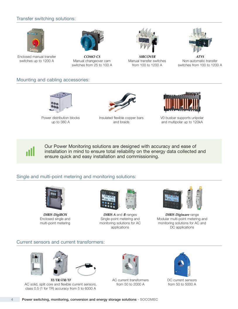
Mounting and cabling accessories:
Power distribution blocks up to 380 A
Insulated flexible copper bars and braids
V0 busbar supports unipolar and multipolar up to 120kA
Our Power Monitoring solutions are designed with accuracy and ease of installation in mind to ensure total reliability on the energy data collected and ensure quick and easy installation and commissioning.
Single and multi-point metering and monitoring solutions:
Current sensors and current transformers:
DIRIS DigiBOXEnclosed single and multi-point metering
TE/TR/iTR/TFAC solid, split core and flexible current sensors, class 0.5 (1 for TR) accuracy from 5 to 6000 A
DIRIS A and B rangesSingle-point metering and
monitoring solutions for AC applications
AC current transformers from 50 to 2000 A
DIRIS Digiware rangeModular multi-point metering and monitoring solutions for AC and
DC applications
DC current sensors from 50 to 5000 A
Transfer switching solutions:
Enclosed manual transfer switches up to 1200 A
COMO CSManual changeover cam
switches from 25 to 100 A
SIRCOVERManual transfer switches
from 100 to 1200 A
ATYSNon-automatic transfer
switches from 100 to 1200 A
5 Power switching, monitoring, conversion and energy storage solutions - SOCOMEC
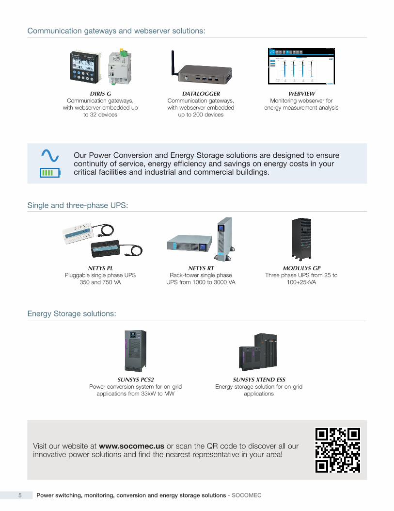
Our Power Conversion and Energy Storage solutions are designed to ensure continuity of service, energy efficiency and savings on energy costs in your critical facilities and industrial and commercial buildings.
Single and three-phase UPS:
Energy Storage solutions:
NETYS PLPluggable single phase UPS
350 and 750 VA
SUNSYS PCS2Power conversion system for on-grid
applications from 33kW to MW
NETYS RTRack-tower single phase
UPS from 1000 to 3000 VA
SUNSYS XTEND ESSEnergy storage solution for on-grid
applications
MODULYS GPThree phase UPS from 25 to
100+25kVA
Visit our website at www.socomec.us or scan the QR code to discover all our innovative power solutions and find the nearest representative in your area!
Communication gateways and webserver solutions:
DIRIS GCommunication gateways,
with webserver embedded up to 32 devices
DATALOGGER Communication gateways, with webserver embedded
up to 200 devices
WEBVIEWMonitoring webserver for
energy measurement analysis
FUSERBLOC UL Fusible disconnect switches UL and CSA
from 30 to 800 A
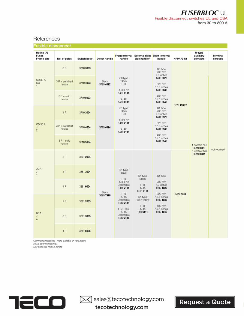
Fusible disconnect
Rating (A) FusesFrame size No. of poles Switch body Direct handle
Front external handle
External right side handle(1)
Shaft external handle NFPA79 kit
U-type auxiliary contacts
Terminal shrouds
CD 30 ACC1
3 P 3710 3003
Black3729 4012
S0 type Black I - 0
1, 3R, 121493 0111
4, 4X
149D 0111
S1 type Black I - 0
1, 3R, 12141F 2111
4, 4X
141D 2111
S0 type 200 mm
7.9 inches1405 0620
320 mm 12.6 inches1405 0632
400 mm 15.7 inches1405 0640
S1 type 200 mm
7.9 inches1401 0520
320 mm 12.6 inches1401 0532
400 mm15.7 inches1401 0540
3729 4532(2)
1 contact NO3999 0701
1 contact NC3999 0702
not required
3 P + switched neutral
3710 4003
3 P + solid neutral
3710 5003
CD 30 AJ2
3 P 3710 3004
3729 4014 3 P + switched
neutral3710 4004
3 P + solid neutral
3710 5004
30 AJ4
2 P 3861 2004
Black3629 7910
S1 type Black
I - 0 1, 3R, 12
Defeatable141F 2111
I - 0 4, 4X
Defeatable141D 2111
I - 0 - Test 4, 4X
Defeatable141D 2115
S1 type Black
I - 0 4, 4X
141H 6111
S1 type Red / yellow
I - 0 4, 4X
141I 6111
S1 type
200 mm 7.9 inches1400 1020
320 mm
12.6 inches1400 1032
400 mm15.7 inches1400 1040
3729 7540
3 P 3861 3004
4 P 3861 6004
60 AJ4
2 P 3861 2005
3 P 3861 3005
4 P 3861 6005
References
Common accessories - more available on next pages.
(1) No door interlocking.
(2) Please use with S1 handle
95General Catalog UL/CSA Ed. 2

FUSERBLOC UL Fusible disconnect switches UL and CSAfrom 30 to 800 A
Rating (A) fusesFrame size
No. of poles Switch body Direct handle
Front external handles
External right side handle(1)
Shaft for external handle NFPA79 kit
U-type auxiliary contacts
Terminal shrouds
60 AJ5
2 P 3861 2006
Black3629 7910
S2 type Black I - 0
1, 3R, 12 Defeatable142F 2111
4, 4X
Defeatable142D 2111
S2 type BlackI - 0
4, 4X142H 6111
Red / yellowI - 0
4, 4X142I 6111
S2 type
200 mm 7.9 inches1400 1020
320 mm
12.6 inches1400 1032
400 mm15.7 inches1400 1040
3729 7540
1 contact type NO
3999 0701 1 contact type
NC3999 0702
not required
3 P 3861 3006
4 P 3861 6006
100 AJ5
2 P 3861 2010
3 P 3861 3010
4 P 3861 6010
200 AJ6
2 P 3861 2020 3898 2020
3 P 3861 3020 3898 3020
4 P 3861 6020 3898 4020
400 AJ7
2 P 3851 2038
3729 7544
3898 2040
3 P 3851 3038 3898 3040
4 P 3851 6038 3898 6040
600 AJ8
2 P 3850 2060
Black3859 6011
S3 type Black I - 0
1, 3R, 12 Defeatable143F 3111
4, 4X Defeatable143D 3111
S3 type
200 mm 7.9 inches1400 1220
320 mm
12.6 inches1400 1232
400 mm15.7 inches1400 1240
3729 7552
2 P3898 2080
3 P3898 3080
4 P3898 4080
3 P 3850 3060
4 P 3850 6060
800 AL8
2 P 3850 2080
3 P 3850 3080
4 P 3850 6080
References (continued)
Common accessories - more available on next pages.
(1) No door interlocking.
Electronic fuse operation indication (FMD)
acce
s_3
19
_a
Use
For fuse cartridge BS88, DIN and UL.
Principle
The FMD detects fuse operation using a bistable relay and a signaling LED.
It can be mounted on a DIN rail, a back plate, next to the FUSERBLOC, or on the door.
For FUSERBLOC 100 to 800 A
Nb of leds Type Operating voltage Ph/Ph Reference
1 FMD10 120 - 260 VAC 3899 11201 FMD10 380 - 690 VAC 3899 13803 FMD30 120 - 260 VAC 3899 31203 FMD30 380 - 690 VAC 3899 3380
acce
s_3
10
_a
References
Accessories Reference
Kit for connection accessories Standard 3819 9120
Kit for connection accessories Door mounted 3829 9120
Relay characteristics
Type
Relay operating current Ic (A)
AC-15 DC-13
FMD10 and FMD30 2.5 A 0.2
FMD10
1-led version
FMD30
3-leds version
Accessories
96 General Catalog UL/CSA Ed. 2

FUSERBLOC UL Fusible disconnect switches UL and CSA
from 30 to 800 A
Rod operator
ul_
04
3_a
Use
Link between the flange handle and the switch. The rod flange is an economical solution, please order the flange handle and a rod kit.
For enclosure depth (inches) For enclosure depth (mm) Reference
8 … 24 203 … 613 3729 9904
sirc
o_2
46
_a_1
_us_
cat
Flange handle for flange operation
Use
Meets both UL 508A and NFPA 79 requirements.
The handle will operate the switch by cable or rod.
Rating (A) Type Nema type Reference
30 … 200 Standard handle 1, 3, 3R, 4, 12 3729 9002(1)
30 … 200 Chrome plated handle 1, 3, 3R, 4, 4X, 12 3729 9003(1)
NFPA79 accessories
NFPA 79 "Through the door" kit
ul_
12
1_b
Use
Meets both UL 508A and NFPA 79 requirements.
Allows retrofit of your installations for ratings from 30 to 800 A.
Please order an S-type external handle separately.
Number of auxiliary contact installed on the switch will be limited to 1 layer (instead of 2).
If more needed please use the S type auxiliary contacts.
Delivered with a 12.6 in / 320 mm shaft.
For longer shafts, please consult us.
Rating (A) Frame size Reference
CD 30 1/2 3729 4532(1)
30 … 200 3 … 6 3729 7540
400 7 3729 7544
600 … 800 8 3729 7552
ul_
04
2_b
_1si
rco
_24
7_a
_1_c
at
Cable operator
Use
Link between the flange handle and the switch, please order the flange handle, the mechanism and a cable length of your choice.
Cable length (inches) Cable length (mm) Reference
36 900 3729 9992
60 1500 3729 9993
120 3000 3729 9994
Rating (A) Description Reference
30 … 200 Cable flange mechanism 3729 9903
For 400 A rating, please consult us.
(1) Defeatable handle.
Rating 30 … 200 A
For 400 A rating, please consult us.
For 400 A rating, please consult us.
(1) Please use with S1 handle.
97General Catalog UL/CSA Ed. 2

FUSERBLOC UL Fusible disconnect switches UL and CSAfrom 30 to 800 A
acce
s_2
61
_a
Rating (A) Color Fuses Fig. Reference
CD 30 Black CC 1 3729 4012
CD 30 Black J 1 3729 4014
30 … 400 Black J 2 3629 7910
600 … 800 Black J / L 2 3859 6011
Fig. 2
acce
s_1
47
_a_2
_cat
Fig.1
Direct handle
Accessories
acce
s_1
49
_a_2
_cat
S- type handle
acce
s_1
64
_a_2
_cat
S2-type handle
External handle
Use
The locking function of the front external handle prevents the user from opening the door of the enclosure when the switch is in the "ON" position, and when the switch is padlocked in the “OFF” position (S1, S2, S3 and S4 type handles only).
Opening the door when the switch is in the "ON" position is possible by defeating the interlocking function with the use of a tool (authorized persons only).
The interlocking function is restored when the door is re-closed.
acce
s_1
51
_a_1
_cat
S3-type handle
acce
s_2
63
_a_2
_cat
S0-type handleRating (A) Frame size Handle type Nema type Test Handle color Reference
CD 30 1/2 S0(1) 1, 3R, 12 I - 0 Black 1493 0111
CD 30 1/2 S0(1) 1, 3R, 12 I - 0 Red/Yellow 1494 0111
CD 30 1/2 S0(1) 4, 4X I - 0 Black 149D 0111
CD 30 1/2 S0 4, 4X I - 0 Red/Yellow 149E 0111
CD 30 … 60 1/2/4 S1 1, 3R, 12 I - 0 Black 141F 2111
CD 30 … 60 1/2/4 S1 1, 3R, 12 I - 0 Red/Yellow 141G 2111
CD 30 … 60 1/2/4 S1 4, 4X I - 0 Black 141D 2111
CD 30 … 60 1/2/4 S1 4, 4X I - 0 Red/Yellow 141E 2111
CD 30 … 60 1/2/4 S1 4, 4X I - 0 - Test Black 141D 2115
CD 30 … 60 1/2/4 S1 4, 4X I - 0 - Test Red/Yellow 141E 2115
60 … 200 5 … 7 S2 4, 4X I - 0 - Test Black 142D 2115
60 … 200 5 … 7 S2 4, 4X I - 0 - Test Red/Yellow 142E 2115
60 … 400 5 … 7 S2 1, 3R, 12 I - 0 Black 142F 2111
60 … 400 5 … 7 S2 1, 3R, 12 I - 0 Red/Yellow 142G 2111
60 … 400 5 … 7 S2 4, 4X I - 0 Black 142D 2111
60 … 400 5 … 7 S2 4, 4X I - 0 Red/Yellow 142E 2111
600 … 800 8 S3 1, 3R, 12 I - 0 Black 143F 3111
600 … 800 8 S3 1, 3R, 12 I - 0 Red/Yellow 143G 3111
600 … 800 8 S3 4, 4X I - 0 Black 143D 3111
600 … 800 8 S3 4, 4X I - 0 Red/Yellow 143E 3111
(1) S0: No interlock in the OFF position.
Front operation
Rating (A) Frame size Handle type Nema type Test Handle color Reference
30 … 60 4 S1 4, 4X I - 0 Black 141H 6111
30 … 60 4 S1 4, 4X I - 0 Red/Yellow 141I 6111
100 … 400 5 … 7 S2 4, 4X I - 0 Black 142H 6111
100 … 400 5 … 7 S2 4, 4X I - 0 Red/Yellow 142I 6111
600 … 800 8 S3 4, 4X I - 0 Black consult us
600 … 800 8 S3 4, 4X I - 0 Red/Yellow consult us
Right side operation
Rating (A) Frame size Handle type Nema type Test Handle color Reference
CD 30 … 60 1/2/4 S1 4, 4X I - 0 Black 141D 2911
CD 30 … 60 1/2/4 S1 4, 4X I - 0 Red/Yellow 141E 2911
60 … 400 5 … 7 S2 4, 4X I - 0 Black 142D 2911
60 … 400 5 … 7 S2 4, 4X I - 0 Red/Yellow 142E 2911
600 … 800 8 S3 4, 4X I - 0 Black 143D 3911
600 … 800 8 S3 4, 4X I - 0 Red/Yellow 143E 3911
Front handle heavy duty I - 0 with metallic lever
98 General Catalog UL/CSA Ed. 2
FUSERBLOC UL Fusible disconnect switches UL and CSA
from 30 to 800 A
acce
s_1
87
_a_1
_cat
Handle color Pack qty External degree of protection (IP) Reference
Black 10 IP65 1493 0000
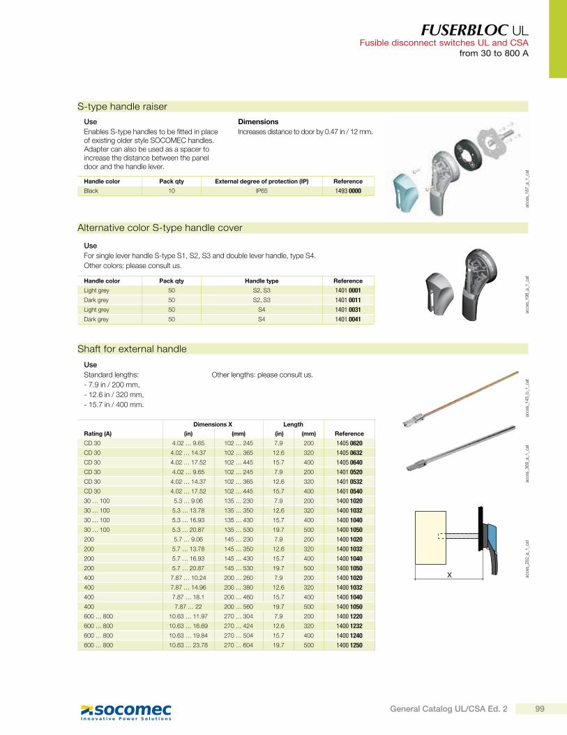
S-type handle raiser
Use
Enables S-type handles to be fitted in place of existing older style SOCOMEC handles. Adapter can also be used as a spacer to increase the distance between the panel door and the handle lever.
Dimensions
Increases distance to door by 0.47 in / 12 mm.
Alternative color S-type handle cover
acce
s_1
98
_a_1
_cat
Use
For single lever handle S-type S1, S2, S3 and double lever handle, type S4.
Other colors: please consult us.
Handle color Pack qty Handle type Reference
Light grey 50 S2, S3 1401 0001
Dark grey 50 S2, S3 1401 0011
Light grey 50 S4 1401 0031
Dark grey 50 S4 1401 0041
X acce
s_2
02
_a_1
_cat
acce
s_3
69
_a_1
_cat
acce
s_1
45
_b_1
_cat
Shaft for external handle
Dimensions X Length
Rating (A) (in) (mm) (in) (mm) Reference
CD 30 4.02 … 9.65 102 … 245 7.9 200 1405 0620
CD 30 4.02 … 14.37 102 … 365 12.6 320 1405 0632
CD 30 4.02 … 17.52 102 … 445 15.7 400 1405 0640
CD 30 4.02 … 9.65 102 … 245 7.9 200 1401 0520
CD 30 4.02 … 14.37 102 … 365 12.6 320 1401 0532
CD 30 4.02 … 17.52 102 … 445 15.7 400 1401 0540
30 … 100 5.3 … 9.06 135 … 230 7.9 200 1400 1020
30 … 100 5.3 … 13.78 135 … 350 12.6 320 1400 1032
30 … 100 5.3 … 16.93 135 … 430 15.7 400 1400 1040
30 … 100 5.3 … 20.87 135 … 530 19.7 500 1400 1050
200 5.7 … 9.06 145 … 230 7.9 200 1400 1020
200 5.7 … 13.78 145 … 350 12.6 320 1400 1032
200 5.7 … 16.93 145 … 430 15.7 400 1400 1040
200 5.7 … 20.87 145 … 530 19.7 500 1400 1050
400 7.87 … 10.24 200 … 260 7.9 200 1400 1020
400 7.87 … 14.96 200 … 380 12.6 320 1400 1032
400 7.87 … 18.1 200 … 460 15.7 400 1400 1040
400 7.87 … 22 200 … 560 19.7 500 1400 1050
600 … 800 10.63 … 11.97 270 … 304 7.9 200 1400 1220
600 … 800 10.63 … 16.69 270 … 424 12.6 320 1400 1232
600 … 800 10.63 … 19.84 270 … 504 15.7 400 1400 1240
600 … 800 10.63 … 23.78 270 … 604 19.7 500 1400 1250
Use
Standard lengths:
- 7.9 in / 200 mm,
- 12.6 in / 320 mm,
- 15.7 in / 400 mm.
Other lengths: please consult us.
99General Catalog UL/CSA Ed. 2

FUSERBLOC UL Fusible disconnect switches UL and CSAfrom 30 to 800 A
acce
s_0
83
_a_1
_catNO+NC auxiliary contacts
Rating (A) Number of contacts Reference
30 … 800 1 3999 U041
30 … 800 2 3999 U042
acce
s_0
51
_a_1
_cat
S-type auxiliary contacts
Use
Side operated auxiliary contacts for FUSERBLOC 30 to 400 A, position OFF and ON signalled by 1 to 4 NO + NC auxiliary contacts.
Electrical characteristics
A600/D600.
S-type auxiliary contacts are signaling position I and 0.
U-type auxiliary contacts
A
Bac
ces_
05
6_a
_1_c
atac
ces_
04
3_a
_1_x
_cat
Use
U-type AC can be configured to be operated on both, standard and TEST position switches from CD 30 to 800 A. Each slot can accommodate up to 2 interlocked ACs.
- For CD 30A/CC, a maximum of 4 ACs (8 with an additional holder):
- For CD 30A/J, maximum 2 ACs (6 with an additional holder),
- For 30 to 200A/J, maximum 4 ACs,
- For 400 to 800A/L, maximum 8 ACs.
Electrical characteristics
A600.
When FUSERBLOC is front operated, ACs are prebreak and signaling position I and 0. When FUSERBLOC is side operated, Acs are signaling positions I and 0.
NO auxiliary contacts
Rating (A) Number of contacts Reference
CD 30 … 800 1 3999 0701
NC auxiliary contacts
Rating (A) Number of contacts Reference
CD 30 … 800 1 3999 0702
Contact holder for additional auxiliary contacts
Rating (A) Fuses Reference
CD 30 CC 3999 0710
CD 30 J 3999 0710
Accessories (continued)
Shaft guide for external handle
acce
s_2
60
_a_2
_cat
Use
This accessory enables handle to engage shaft with a misalignment of up to 0.59 in / 15 mm.
Required for a shaft length over 400 mm for S1 to S3 handles and for a shaft from 12.6 in / 320 mm for S0 handle.
Description Reference
Shaft guide for S1 to S3 handles 1429 0000
Shaft guide for S0 handle 1419 0000
CD 30 : U-type auxiliary contacts cannot be mounted on switches with direct operation handle
External front operation shaft support accessory
Use
This support maintains shaft position for extension shafts greater than 12.6 in / 320 mm in length.
Rating (A) Frame size Reference
50 … 400 11 … 16 3899 0400
fuse
r_6
98
_a_2
_cat
100 General Catalog UL/CSA Ed. 2

FUSERBLOC UL Fusible disconnect switches UL and CSA
from 30 to 800 A
Terminal shrouds
fuse
r_3
14
_a_1
_cat
Use
Top or bottom protection against direct contact with terminals or connection parts.
2 sets required to fully shroud both line and load terminals.
Front and side operation
Rating (A) No. of poles Reference(1)
30 … 100 2/3/4 P as standard
200 2 P 3898 2020200 3 P 3898 3020200 4 P 3898 4020400 2 P 3898 2040(2)
400 3 P 3898 3040 (2)
400 4 P 3898 6040 (2)
600 … 800 2 P 3898 2080(3)
600 … 800 3 P 3898 3080(3)
600 … 800 4 P 3898 4080(3)
(1) Top or bottom. (2) Not compatible with 2 wire lugs (3954x041). (3) Line side delivered as standard.
ul_
03
2_a
Terminals lugsUse
Connection of cables to the terminals.
Rating (A) Wires range No wires per lug Lugs per kit Wires Reference
CD 30 #14 - #10 1 Cu as standard
30 #14 - #10 1 Cu as standard
30 … 60 #10 - #6 1 Cu as standard
60 … 100 #12 - #1 1 Cu as standard
200 #6 - 300MCM 1 2 Cu / Al 3954 2020200 #6 - 300MCM 1 3 Cu / Al 3954 3020200 #6 - 300MCM 1 4 Cu / Al 3954 4020400 #2 - 600MCM 1 2 Cu / Al 3954 2040400 #2 - 600MCM 1 3 Cu / Al 3954 3040
400 #2 - 600MCM 1 4 Cu / Al 3954 4040
400 2 x (#6 - 350 MCM) 2 2 Cu / Al 3954 2041400 2 x (#6 - 350 MCM) 2 3 Cu / Al 3954 3041400 2 x (#6 - 350 MCM) 2 4 Cu / Al 3954 4041600 … 800 2 x (#2 - 600MCM) 1 2 Cu / Al 3954 2060600 … 800 2 x (#2 - 600MCM) 2 3 Cu / Al 3954 3060600 … 800 2 x (#2 - 600MCM) 2 4 Cu / Al 3954 4060
Class T fuse adapter
Use
The adapter makes it possible to fit class T fuses in the FUSERBLOC fuse switches.
Size Class T fuse
Rating (A) (in) (mm) No. of poles Reference
100 2.34 59.5 3 P 3729 8010200 2.48 63 3 P 3729 8020400 2.71 69 3 P 3729 8040600 2.95 75 3 P 3729 8060800 3.17 80.5 3 P 3729 8080
fuse
r-ul_
01
4_b
_1_c
at
Solid links
Rating (A) Fuses No of links per kit Reference
100 J 3 3799 9010200 J 3 3799 9020400 J 3 3799 9040600 … 800 J / L 3 3799 9080
fuse
r-ul_
01
9_a
_1_c
at
101General Catalog UL/CSA Ed. 2