UL COPYRIGHTED MATERIAL NOT AUTHORIZED FOR...
56
Document Was Downloaded By Lujun Lujun For Use By JE WOO CORP LTD 43718 : 8/20/2009 - 10:08 PM UL COPYRIGHTED MATERIAL – NOT AUTHORIZED FOR FURTHER REPRODUCTION OR DISTRIBUTION WITHOUT PERMISSION FROM UL Subject 8750 May 29, 2009 SUMMARY OF TOPICS The following requirements for the Standard for Light Emitting Diode (LED) Equipment for Use in Lighting Products, UL 8750, are being proposed: 1. This proposed First Edition of the Standard for Light Emitting Diode (LED) Equipment for Use in Lighting Products, UL 8750, includes the following major changes from the Outline of Investigation, Subject 8750: a) Revised title to reflect intended range of products covered by the standard; b) Revised Scope, Section 1, to reflect intended range of products covered by the standard; c) Added, removed, and revised glossary definitions; d) Removed General section and replaced with Power Supplies, LED Drivers, and Transformers; e) Added provision to Environmental Considerations for potted or conformal coated constructions; f) Revised Mechanical Construction to consolidate mechanical construction requirements into one section; g) Revised Electrical Construction to consolidate electrical construction requirements into one section; h) Revised Internal Wiring to expand considerations for wiring smaller than 18 AWG; i) Added requirements for both Permanently-Connected Units and Cord-Connected and Direct Plug-In Units; j) Added requirements for Coil Insulation for LED drivers employing coil forms; k) Relocated Performance Tests and Abnormal Conditions Tests into one section for Performance Tests; l) Relocated Markings section; m) Added supply wiring temperature marking STP BALLOTS AND COMMENTS DUE: July 28, 2009 1. This proposed First Edition of the Standard for Light Emitting Diode (LED) Equipment for Use in Lighting Products, UL 8750, includes the following major changes from the Outline of Investigation, Subject 8750: a) Revised title to reflect intended range of products covered by the standard; b) Revised Scope, Section 1, to reflect intended range of products covered by the standard; c) Added, removed, and revised glossary definitions; d) Removed General section and replaced with Power Supplies, LED Drivers, and Transformers; e) Added provision to Environmental Considerations for potted or conformal coated constructions; f) Revised Mechanical Construction to consolidate mechanical construction requirements into one section; g) Revised Electrical Construction to consolidate electrical construction requirements into one section; h) Revised Internal Wiring to expand considerations for wiring smaller than 18 AWG; i) Added requirements for both Permanently-Connected Units and Cord-Connected and Direct Plug-In Units; j) Added requirements for Coil Insulation for LED drivers employing coil forms; k) Relocated Performance Tests and Abnormal Conditions Tests into one section for Performance Tests; l) Relocated Markings section; m) Added supply wiring temperature marking RATIONALE Proposal submitted by: Ed Joseph, UL
Transcript of UL COPYRIGHTED MATERIAL NOT AUTHORIZED FOR...

Do
cum
ent W
as Do
wn
load
ed B
y Lu
jun
Lu
jun
Fo
r Use B
y JE W
OO
CO
RP
LT
D 43718 : 8/20/2009 - 10:08 P
M
UL COPYRIGHTED MATERIAL –NOT AUTHORIZED FOR FURTHER REPRODUCTION OR
DISTRIBUTION WITHOUT PERMISSION FROM UL
Subject 8750May 29, 2009
SUMMARY OF TOPICS
The following requirements for the Standard for Light Emitting Diode (LED) Equipment for Use inLighting Products, UL 8750, are being proposed:
1. This proposed First Edition of the Standard for Light Emitting Diode (LED) Equipmentfor Use in Lighting Products, UL 8750, includes the following major changes from theOutline of Investigation, Subject 8750: a) Revised title to reflect intended range ofproducts covered by the standard; b) Revised Scope, Section 1, to reflect intended rangeof products covered by the standard; c) Added, removed, and revised glossarydefinitions; d) Removed General section and replaced with Power Supplies, LED Drivers,and Transformers; e) Added provision to Environmental Considerations for potted orconformal coated constructions; f) Revised Mechanical Construction to consolidatemechanical construction requirements into one section; g) Revised ElectricalConstruction to consolidate electrical construction requirements into one section; h)Revised Internal Wiring to expand considerations for wiring smaller than 18 AWG; i)Added requirements for both Permanently-Connected Units and Cord-Connected andDirect Plug-In Units; j) Added requirements for Coil Insulation for LED drivers employingcoil forms; k) Relocated Performance Tests and Abnormal Conditions Tests into onesection for Performance Tests; l) Relocated Markings section; m) Added supply wiringtemperature marking
STP BALLOTS AND COMMENTS DUE: July 28, 2009
1. This proposed First Edition of the Standard for Light Emitting Diode (LED) Equipment for Usein Lighting Products, UL 8750, includes the following major changes from the Outline ofInvestigation, Subject 8750: a) Revised title to reflect intended range of products covered by thestandard; b) Revised Scope, Section 1, to reflect intended range of products covered by thestandard; c) Added, removed, and revised glossary definitions; d) Removed General section andreplaced with Power Supplies, LED Drivers, and Transformers; e) Added provision toEnvironmental Considerations for potted or conformal coated constructions; f) RevisedMechanical Construction to consolidate mechanical construction requirements into one section;g) Revised Electrical Construction to consolidate electrical construction requirements into onesection; h) Revised Internal Wiring to expand considerations for wiring smaller than 18 AWG; i)Added requirements for both Permanently-Connected Units and Cord-Connected and DirectPlug-In Units; j) Added requirements for Coil Insulation for LED drivers employing coil forms; k)Relocated Performance Tests and Abnormal Conditions Tests into one section for Performance
Tests; l) Relocated Markings section; m) Added supply wiring temperature marking
RATIONALE
Proposal submitted by: Ed Joseph, UL

Do
cum
ent W
as Do
wn
load
ed B
y Lu
jun
Lu
jun
Fo
r Use B
y JE W
OO
CO
RP
LT
D 43718 : 8/20/2009 - 10:08 P
M
UL COPYRIGHTED MATERIAL –NOT AUTHORIZED FOR FURTHER REPRODUCTION OR
DISTRIBUTION WITHOUT PERMISSION FROM UL
UL has determined that there is sufficient need and interest for developing a First Edition of theStandard for Light Emitting Diode (LED) Equipment for Use in Lighting Products, UL 8750. Theproposed standard is based on UL’s currently published Third Issue of the Outline of Investigation forLight Emitting Diode (LED) Light Sources for Use in Lighting Products, Subject 8750.
The Proposed First Edition of the Standard for Light Emitting Diode (LED) Equipment for Use in LightingProducts, UL 8750, includes the following changes from the previous published Third Issue of theOutline of Investigation for Light Emitting Diode (LED) Light Sources for Use in Lighting Products,Subject 8750. Aside from these noted changes, minor editorial changes and rearrangement ofthe requirements within the standard were made for ease of use.
a) Revision to the title to reflect the intended range of products covered by the standard. In thetitle of the standard, the term “Equipment” replaces “Light Sources.”
b) Revisions to the Scope, Section 1, to reflect the intended range of products covered by thestandard. The Scope was revised to specify component parts including LED drivers, controllers,arrays, modules, and packages.
c) Changes to Definitions, Section 3, as follows:
Removed: The following definitions were removed as these terms were not referencedin the standard:
• circuit, extra-low voltage
• circuit, limited current
• circuit, safety extra low voltage
• enclosure, mechanical
• lamp
• LED lamp, integrated
• LED lamp, non-integrated
• LED luminaire
• LED module
• Pollution Degrees (1, 2, and 3)
• power source, Class 2 or Limited Power Source (LPS)
• rated maximum temperature, Tc
Added: The following definitions were added as these terms are referenced in thestandard:
• barrier
• LED control module
MAY 29, 2009SUBJECT 8750 -2-

Do
cum
ent W
as Do
wn
load
ed B
y Lu
jun
Lu
jun
Fo
r Use B
y JE W
OO
CO
RP
LT
D 43718 : 8/20/2009 - 10:08 P
M
UL COPYRIGHTED MATERIAL –NOT AUTHORIZED FOR FURTHER REPRODUCTION OR
DISTRIBUTION WITHOUT PERMISSION FROM UL
• insulation-piercing terminal
• environmental locations (dry, damp, wet)
• PLC value
• power source, Low Voltage Limited Energy (LVLE)
Revised:
• The definition of LED array was revised to combine the definitions for LEDarray and LED module for the purpose of clarification of terms.
• Risk of fire was also revised in order to align with the definition of Class 2 andLVLE circuits.
d) Removed General from previous Section 4 and replaced with new Power Supplies, LEDDrivers, and Transformers, Section 4, including the following changes:
1) Requirement of previous paragraph 4.2 for “double insulated” products was removedas it was not anticipated that products covered by the standard would be designed inthis fashion.
2) Generalized statement of previous paragraph 4.1 addressing the relationship ofrequirements in this standard to applicable end-use lighting standard was relocated intoparagraphs 6.1.1, 7.1.1, and 8.1.1.
3) Added paragraphs 4.1 and 4.2 for power supplies, LED drivers, and transformers torelocate previous Sections 8.3 and 8.4 of the Third Issue of the Outline of Investigation.
e) Added provision to Environmental Considerations, Section 5, for constructions that are pottedor conformal coated. Section 5 was revised to introduce an exception to the environmentalcondition tests for damp and wet location units that are potted or provided with a conformalcoating. These added provisions are consistent with the requirements in the Standard forFluorescent-Lamp Ballasts, UL 935.
f) Revised Mechanical Construction, Section 6, to consolidate mechanical constructionrequirements of previous Sections, 6, 8, and 9 into one section of the standard, including thefollowing changes:
1) Section 6 was revised to consolidate metal enclosure and polymeric enclosure andmaterial requirements for LED power sources, LED arrays, controllers, and packagesinto one location within the standard.
2) Added an exception in Section 6.2 for reduced metal enclosure thickness based on amechanical strength test introduced in Section 8.13. This requirement is consistentwith the requirement for reduced metal thickness in the Standard for Luminaires, UL1598.
3) Material flammability requirements and electrical properties requirements for LEDlens materials were added in Table 6.2 and paragraph 6.3.4 taking into considerationthe small size of this component part.
MAY 29, 2009SUBJECT 8750 -3-

Do
cum
ent W
as Do
wn
load
ed B
y Lu
jun
Lu
jun
Fo
r Use B
y JE W
OO
CO
RP
LT
D 43718 : 8/20/2009 - 10:08 P
M
UL COPYRIGHTED MATERIAL –NOT AUTHORIZED FOR FURTHER REPRODUCTION OR
DISTRIBUTION WITHOUT PERMISSION FROM UL
g) Revised Electrical Construction, Section 7, to consolidate electrical construction requirementsof previous Section 7, 8, and 9 into one section of the standard. This section now coverselectrical construction requirements for LED power sources, LED arrays, controllers andpackages.
h) Revised Internal Wiring, Section 7.3, to expand considerations for wiring smaller than 18AWG. These requirements are consistent with the internal wiring requirements in the Standardfor Luminaires, UL 1598.
i) Added Permanently-Connected Units, Section 7.4.2, and Cord-Connected and Direct Plug-InUnits, Section 7.4.3. Requirements were added for supply and load connection of permanentlyconnected, cord-connected, or direct plug in LED drivers. These requirements are consistentwith the supply connection requirements in the Standard for Electric Sign Components, UL 879.
j) Added requirements for Coil Insulation, Section 7.11, for LED drivers employing coil forms.These requirements are consistent with the coil insulation requirements in the Standard forClass 2 Power Units, UL 1310.
k) Relocated Performance Tests from previous Section 10, and Abnormal Conditions Tests,from previous Section 11, into Performance Tests, Section 8. Tests have been added to thissection to replace test methods referencing other standards. Requirements were also added fortests applicable to LED drivers. The following tests were added to Section 8:
1) Temperature test, Section 8.3,
2) Output loading test, Section 8.5.3,
3) Leakage current measurement test, Section 8.7,
4) Cord strain and pushback relief test, Section 8.8,
5) Security of output terminals, Section 8.9,
6) Insulation piercing connection thermal cycling test, Section 8.10,
7) Adhesive support test, Section 8.11,
8) Environmental tests, Section 8.12,
9) Mechanical strength test for metal enclosures, Section 8.13.
l) Relocated Markings from previous Section 12 to new Section 9. Changes to the text areeditorial in nature.
m) Added supply wiring temperature marking to Section 9.3. This marking requirement wasadded to accommodate supply wiring temperatures in excess of 60°C based on the temperaturetest and of Section 8.3 and this marking provision.
MAY 29, 2009SUBJECT 8750 -4-

Do
cum
ent W
as Do
wn
load
ed B
y Lu
jun
Lu
jun
Fo
r Use B
y JE W
OO
CO
RP
LT
D 43718 : 8/20/2009 - 10:08 P
M
UL COPYRIGHTED MATERIAL –NOT AUTHORIZED FOR FURTHER REPRODUCTION OR
DISTRIBUTION WITHOUT PERMISSION FROM UL
CONTENTS
INTRODUCTION
1 Scope . . . . . . . . . . . . . . . . . . . . . . . . . . . . . . . . . . . . . . . . . . . . . . . . . . . . . . . . . . . . . . . . . . . . . . . . . . . . . . .82 General . . . . . . . . . . . . . . . . . . . . . . . . . . . . . . . . . . . . . . . . . . . . . . . . . . . . . . . . . . . . . . . . . . . . . . . . . . . . . .8
2.1 Components . . . . . . . . . . . . . . . . . . . . . . . . . . . . . . . . . . . . . . . . . . . . . . . . . . . . . . . . . . . . . . . . . . .82.2 Units of measurement . . . . . . . . . . . . . . . . . . . . . . . . . . . . . . . . . . . . . . . . . . . . . . . . . . . . . . . . . . .92.3 Reference publications . . . . . . . . . . . . . . . . . . . . . . . . . . . . . . . . . . . . . . . . . . . . . . . . . . . . . . . . . .9
3 Definitions . . . . . . . . . . . . . . . . . . . . . . . . . . . . . . . . . . . . . . . . . . . . . . . . . . . . . . . . . . . . . . . . . . . . . . . . . . . .94 Power supplies, LED Drivers, and Transformers . . . . . . . . . . . . . . . . . . . . . . . . . . . . . . . . . . . . . . . . .11
CONSTRUCTION
5 Environmental Considerations . . . . . . . . . . . . . . . . . . . . . . . . . . . . . . . . . . . . . . . . . . . . . . . . . . . . . . . . .126 Mechanical Construction . . . . . . . . . . . . . . . . . . . . . . . . . . . . . . . . . . . . . . . . . . . . . . . . . . . . . . . . . . . . . .12
6.1 General . . . . . . . . . . . . . . . . . . . . . . . . . . . . . . . . . . . . . . . . . . . . . . . . . . . . . . . . . . . . . . . . . . . . . .126.2 Metal thickness . . . . . . . . . . . . . . . . . . . . . . . . . . . . . . . . . . . . . . . . . . . . . . . . . . . . . . . . . . . . . . .136.3 Polymeric materials for enclosures and electrical insulation . . . . . . . . . . . . . . . . . . . . . . . . .146.4 Enclosure openings . . . . . . . . . . . . . . . . . . . . . . . . . . . . . . . . . . . . . . . . . . . . . . . . . . . . . . . . . . . .156.5 Conductor protection . . . . . . . . . . . . . . . . . . . . . . . . . . . . . . . . . . . . . . . . . . . . . . . . . . . . . . . . . . .156.6 Strain relief . . . . . . . . . . . . . . . . . . . . . . . . . . . . . . . . . . . . . . . . . . . . . . . . . . . . . . . . . . . . . . . . . . .156.7 Potting compound . . . . . . . . . . . . . . . . . . . . . . . . . . . . . . . . . . . . . . . . . . . . . . . . . . . . . . . . . . . . .16
7 Electrical Construction . . . . . . . . . . . . . . . . . . . . . . . . . . . . . . . . . . . . . . . . . . . . . . . . . . . . . . . . . . . . . . . .167.1 General . . . . . . . . . . . . . . . . . . . . . . . . . . . . . . . . . . . . . . . . . . . . . . . . . . . . . . . . . . . . . . . . . . . . . .167.2 Accessibility . . . . . . . . . . . . . . . . . . . . . . . . . . . . . . . . . . . . . . . . . . . . . . . . . . . . . . . . . . . . . . . . . .167.3 Internal wiring . . . . . . . . . . . . . . . . . . . . . . . . . . . . . . . . . . . . . . . . . . . . . . . . . . . . . . . . . . . . . . . . .187.4 Supply and load connections . . . . . . . . . . . . . . . . . . . . . . . . . . . . . . . . . . . . . . . . . . . . . . . . . . .20
7.4.1 General . . . . . . . . . . . . . . . . . . . . . . . . . . . . . . . . . . . . . . . . . . . . . . . . . . . . . . . . . . . . . . . .207.4.2 Permanently-connected units . . . . . . . . . . . . . . . . . . . . . . . . . . . . . . . . . . . . . . . . . . . . .207.4.3 Cord-connected and direct plug-in units . . . . . . . . . . . . . . . . . . . . . . . . . . . . . . . . . . .237.4.4 Leads, terminals, and connectors for other than branch circuit connections . . . .26
7.5 Separation of circuits . . . . . . . . . . . . . . . . . . . . . . . . . . . . . . . . . . . . . . . . . . . . . . . . . . . . . . . . . .267.6 Insulating materials . . . . . . . . . . . . . . . . . . . . . . . . . . . . . . . . . . . . . . . . . . . . . . . . . . . . . . . . . . . .277.7 Printed wiring boards . . . . . . . . . . . . . . . . . . . . . . . . . . . . . . . . . . . . . . . . . . . . . . . . . . . . . . . . . .277.8 Electrical spacings . . . . . . . . . . . . . . . . . . . . . . . . . . . . . . . . . . . . . . . . . . . . . . . . . . . . . . . . . . . . .287.9 Circuit components . . . . . . . . . . . . . . . . . . . . . . . . . . . . . . . . . . . . . . . . . . . . . . . . . . . . . . . . . . . .297.10 Protective devices . . . . . . . . . . . . . . . . . . . . . . . . . . . . . . . . . . . . . . . . . . . . . . . . . . . . . . . . . . . .307.11 Coil insulation . . . . . . . . . . . . . . . . . . . . . . . . . . . . . . . . . . . . . . . . . . . . . . . . . . . . . . . . . . . . . . . .30
7.11.1 General . . . . . . . . . . . . . . . . . . . . . . . . . . . . . . . . . . . . . . . . . . . . . . . . . . . . . . . . . . . . . . .307.11.2 Insulation for transformers . . . . . . . . . . . . . . . . . . . . . . . . . . . . . . . . . . . . . . . . . . . . . .31
7.12 Class 2 output circuits . . . . . . . . . . . . . . . . . . . . . . . . . . . . . . . . . . . . . . . . . . . . . . . . . . . . . . . .34
PERFORMANCE
8 Performance Tests . . . . . . . . . . . . . . . . . . . . . . . . . . . . . . . . . . . . . . . . . . . . . . . . . . . . . . . . . . . . . . . . . . .348.1 General . . . . . . . . . . . . . . . . . . . . . . . . . . . . . . . . . . . . . . . . . . . . . . . . . . . . . . . . . . . . . . . . . . . . . .348.2 Input test . . . . . . . . . . . . . . . . . . . . . . . . . . . . . . . . . . . . . . . . . . . . . . . . . . . . . . . . . . . . . . . . . . . . .348.3 Temperature test . . . . . . . . . . . . . . . . . . . . . . . . . . . . . . . . . . . . . . . . . . . . . . . . . . . . . . . . . . . . . .358.4 Dielectric voltage withstand test . . . . . . . . . . . . . . . . . . . . . . . . . . . . . . . . . . . . . . . . . . . . . . . . .388.5 Abnormal tests . . . . . . . . . . . . . . . . . . . . . . . . . . . . . . . . . . . . . . . . . . . . . . . . . . . . . . . . . . . . . . . .39
8.5.1 General . . . . . . . . . . . . . . . . . . . . . . . . . . . . . . . . . . . . . . . . . . . . . . . . . . . . . . . . . . . . . . . .39
MAY 29, 2009SUBJECT 8750 -5-

Do
cum
ent W
as Do
wn
load
ed B
y Lu
jun
Lu
jun
Fo
r Use B
y JE W
OO
CO
RP
LT
D 43718 : 8/20/2009 - 10:08 P
M
UL COPYRIGHTED MATERIAL –NOT AUTHORIZED FOR FURTHER REPRODUCTION OR
DISTRIBUTION WITHOUT PERMISSION FROM UL
8.5.2 Component failure test . . . . . . . . . . . . . . . . . . . . . . . . . . . . . . . . . . . . . . . . . . . . . . . . . .398.5.3 Output loading test . . . . . . . . . . . . . . . . . . . . . . . . . . . . . . . . . . . . . . . . . . . . . . . . . . . . . .408.5.4 Output loading – alternate method . . . . . . . . . . . . . . . . . . . . . . . . . . . . . . . . . . . . . . . .41
8.6 50-Watt point power measurement test . . . . . . . . . . . . . . . . . . . . . . . . . . . . . . . . . . . . . . . . . .418.7 Leakage current measurement test . . . . . . . . . . . . . . . . . . . . . . . . . . . . . . . . . . . . . . . . . . . . . .438.8 Cord strain and pushback relief test . . . . . . . . . . . . . . . . . . . . . . . . . . . . . . . . . . . . . . . . . . . . .458.9 Security of output terminals . . . . . . . . . . . . . . . . . . . . . . . . . . . . . . . . . . . . . . . . . . . . . . . . . . . . .468.10 Insulation-piercing connection thermal cycling test . . . . . . . . . . . . . . . . . . . . . . . . . . . . . . . .468.11 Adhesive support test . . . . . . . . . . . . . . . . . . . . . . . . . . . . . . . . . . . . . . . . . . . . . . . . . . . . . . . . .478.12 Environmental tests . . . . . . . . . . . . . . . . . . . . . . . . . . . . . . . . . . . . . . . . . . . . . . . . . . . . . . . . . .47
8.12.1 Humidity exposure . . . . . . . . . . . . . . . . . . . . . . . . . . . . . . . . . . . . . . . . . . . . . . . . . . . . .478.12.2 Water exposure . . . . . . . . . . . . . . . . . . . . . . . . . . . . . . . . . . . . . . . . . . . . . . . . . . . . . . .48
8.13 Mechanical strength tests for metal enclosures . . . . . . . . . . . . . . . . . . . . . . . . . . . . . . . . . .519 Markings . . . . . . . . . . . . . . . . . . . . . . . . . . . . . . . . . . . . . . . . . . . . . . . . . . . . . . . . . . . . . . . . . . . . . . . . . . . .51
9.1 General . . . . . . . . . . . . . . . . . . . . . . . . . . . . . . . . . . . . . . . . . . . . . . . . . . . . . . . . . . . . . . . . . . . . . .519.2 Identification and ratings . . . . . . . . . . . . . . . . . . . . . . . . . . . . . . . . . . . . . . . . . . . . . . . . . . . . . . .529.3 Construction-related markings . . . . . . . . . . . . . . . . . . . . . . . . . . . . . . . . . . . . . . . . . . . . . . . . . . .53
APPENDIX A
Standards for Components. . . . . . . . . . . . . . . . . . . . . . . . . . . . . . . . . . . . . . . . . . . . . . . . . . . . . . . . . . . . . A54
MAY 29, 2009SUBJECT 8750 -6-

Do
cum
ent W
as Do
wn
load
ed B
y Lu
jun
Lu
jun
Fo
r Use B
y JE W
OO
CO
RP
LT
D 43718 : 8/20/2009 - 10:08 P
M
UL COPYRIGHTED MATERIAL –NOT AUTHORIZED FOR FURTHER REPRODUCTION OR
DISTRIBUTION WITHOUT PERMISSION FROM UL
PROPOSAL
MAY 29, 2009SUBJECT 8750 -7-

Do
cum
ent W
as Do
wn
load
ed B
y Lu
jun
Lu
jun
Fo
r Use B
y JE W
OO
CO
RP
LT
D 43718 : 8/20/2009 - 10:08 P
M
UL COPYRIGHTED MATERIAL –NOT AUTHORIZED FOR FURTHER REPRODUCTION OR
DISTRIBUTION WITHOUT PERMISSION FROM UL
INTRODUCTION
1 Scope
1.1 These requirements cover LED equipment that is an integral part of a luminaire or other equipmentand which operates in the visible light spectrum between 400 – 700 nm. These requirements also coverthe component parts of light emitting diode (LED) equipment, including LED drivers, controllers, arrays,modules, and packages as defined within this standard.
1.2 These lighting products are intended for installation on branch circuits of 600 V nominal or less inaccordance with the National Electrical Code (NEC), ANSI/NFPA 70, and for connection to isolated(non-utility connected) power sources such as generators, batteries, fuel cells, solar cells, and the like.
1.3 LED equipment is utilized in lighting products that comply with the end-product standards listed below.The requirements in this standard are intended to supplement those in other end-product standards.Included are:
a) Electric Signs, UL 48,
b) Portable Electric Luminaires, UL 153,
c) Underwater Luminaires and Submersible Junction Boxes, UL 676,
d) Emergency Lighting and Power Equipment, UL 924,
e) Stage and Studio Luminaires and Connector Strips, UL 1573,
f) Track Lighting Systems, UL 1574,
g) Luminaires, UL 1598,
h) Direct Plug-In Nightlights, UL 1786,
i) Low Voltage Landscape Lighting Systems, UL 1838,
j) Self-Ballasted Lamps and Lamp Adapters, UL 1993,
k) Luminous Egress Path Marking Systems, UL 1994, and
l) Low Voltage Lighting Systems, UL 2108.
2 General
2.1 Components
2.1.1 Except as indicated in this clause, a component of a product covered by this standard shall complywith the requirements for that component. See the Standards for Components appendix for a list ofstandards covering components generally used in the products covered by this standard.
MAY 29, 2009SUBJECT 8750 -8-

Do
cum
ent W
as Do
wn
load
ed B
y Lu
jun
Lu
jun
Fo
r Use B
y JE W
OO
CO
RP
LT
D 43718 : 8/20/2009 - 10:08 P
M
UL COPYRIGHTED MATERIAL –NOT AUTHORIZED FOR FURTHER REPRODUCTION OR
DISTRIBUTION WITHOUT PERMISSION FROM UL
2.1.2 A component is not required to comply with a specific requirement that:
a) Involves a feature or characteristic not required in the application of the component in theproduct covered by this standard, or
b) Is superseded by a requirement in this standard.
2.1.3 A component shall be used in accordance with its rating established for the intended conditions ofuse.
2.1.4 Specific components are incomplete in construction features or restricted in performancecapabilities. Such components are intended for use only under limited conditions, such as certaintemperatures not exceeding specified limits, and shall be used only under those specific conditions.
2.2 Units of measurement
2.2.1 Except for conductor size, values stated without parentheses are the requirement. Values inparentheses are explanatory or approximate information.
2.2.2 All values of voltage and current are true root mean square (rms) values unless otherwise indicated.
2.2.3 For customary purposes wire sizes are in American Wire Gauge (AWG).
2.3 Reference publications
2.3.1 Any undated reference to a code or standard appearing in the requirements of this standard shallbe interpreted as referring to the latest edition of that code or standard.
3 Definitions
3.1 For the purpose of these requirements, the following definitions apply.
3.2 BARRIER – A part of the unit intended to physically limit access to parts that pose a risk of electricshock.
3.3 CIRCUIT, CLASS 2 – A circuit supplied by an isolating source that complies with the requirementsof the Standard for Class 2 Power Units, UL 1310, or the Class 2 requirements of the Standard for LowVoltage Transformers – Part 3: Class 2 and Class 3 Transformers, UL 5085-3.
3.4 CIRCUIT, LOW VOLTAGE LIMITED ENERGY (LVLE) – A circuit supplied by a transformer-isolated source with a maximum output voltage of 42.4 V peak ac (30 V rms) or 60 V dc; and amaximum output current limited to:
a) 8 A for 0 – 42 V peak ac, or 0 – 30 V dc, or
b) 150 divided by the maximum voltage for 30 – 60 V dc.
3.5 ENCLOSURE, ELECTRICAL – A part of the equipment intended to limit access to parts that areoperating at voltage levels in excess of Class 2 or LVLE.
3.6 ENCLOSURE, FIRE – A part of the equipment that is intended to minimize the spread of fire orflames from within a product.
MAY 29, 2009SUBJECT 8750 -9-

Do
cum
ent W
as Do
wn
load
ed B
y Lu
jun
Lu
jun
Fo
r Use B
y JE W
OO
CO
RP
LT
D 43718 : 8/20/2009 - 10:08 P
M
UL COPYRIGHTED MATERIAL –NOT AUTHORIZED FOR FURTHER REPRODUCTION OR
DISTRIBUTION WITHOUT PERMISSION FROM UL
3.7 ENVIRONMENTAL LOCATIONS
a) DRY LOCATION – A location not normally subject to dampness, but may include a locationsubject to temporary dampness, as in the case of a building under construction, providedventilation is adequate to prevent an accumulation of moisture.
b) DAMP LOCATION – An exterior or interior location that is normally or periodically subject tocondensation of moisture in, on, or adjacent to, electrical equipment, and includes partiallyprotected locations.
c) WET LOCATION – A location in which water can drip, splash, or flow on or against electricalequipment.
3.8 INSULATION-PIERCING TERMINAL – A terminal having a contact pin that punctures theconductor insulation and penetrates between the conductor strands.
3.9 ISOLATED OUTPUT – A circuit with only magnetic, capacitive, or optical connection to anyground-referenced supply source. A low voltage circuit derived by a dropping resistor is not isolated.
3.10 LED (LIGHT EMITTING DIODE) – A solid-state component embodying a p-n junction, emittingoptical radiation when excited by an electric current.
3.11 LED ARRAY – An assembly of LED packages on a printed circuit board, typically with optics andadditional thermal, mechanical, and electrical interfaces. Also referred to as an LED module.
3.12 LED CONTROL MODULE (LED CONTROLLER) – Electronic circuitry interposed between thepower source and an LED array to dim, switch, or otherwise control the electrical energy to the LEDarray. The device does not contain a power source and is not connected directly to the branch circuit.
3.13 LED DRIVER – A power source that adjusts the voltage or current to LEDs, ranging in complexityfrom a resistor to a constant voltage or constant current power supply. Also referred to as Lamp ControlGear. (See also Power Source.)
3.14 LED PACKAGE – An assembly of one or more LED die that contains wire bond connections andmay include an optical element and thermal, mechanical, and electrical interfaces. The package doesnot include a power source and is not connected directly to the branch circuit.
3.15 MEASUREMENT INDICATION UNIT (MIU) – The rms equivalent value of a 60 Hz sinusoidalleakage current in milliamps (mA), adjusted to compensate as necessary for leakage currentscomposed of complex waveforms or frequencies other than 50 or 60 Hz. It is determined by dividing theoutput voltage (V3) in millivolts (mV) rms by 500 (the value in ohms of the resistance in parallel with V2)in the measurement instrument circuit in Figure 8.3.
3.16 PART, DEAD CONDUCTIVE – A conductive part with or without basic insulation that, undernormal operating conditions, carries no electrical current. A grounded dead conductive part may carryonly leakage current.
3.17 PART, HAZARDOUS LIVE – A part located in a circuit that is operating in excess of the risk ofelectric shock or risk of fire limits.
3.18 PART, LIVE – A conductive part that has an electrical difference of potential with respect to earthground or any other conductive part. A part connected to a grounded supply (neutral) conductor isconsidered to be a live part.
MAY 29, 2009SUBJECT 8750 -10-

Do
cum
ent W
as Do
wn
load
ed B
y Lu
jun
Lu
jun
Fo
r Use B
y JE W
OO
CO
RP
LT
D 43718 : 8/20/2009 - 10:08 P
M
UL COPYRIGHTED MATERIAL –NOT AUTHORIZED FOR FURTHER REPRODUCTION OR
DISTRIBUTION WITHOUT PERMISSION FROM UL
3.19 PLC (PERFORMANCE LEVEL CHARACTERISTIC) VALUE – An integer that defines a range oftest values for a given electrical/mechanical property test for polymeric (plastic) materials as defined inthe Standard for Polymeric Materials – Use in Electrical Equipment Evaluations, UL 746C.
3.20 POWER SOURCE, CLASS 2 – An electrical source, such as a transformer or power supply thatcomplies with the requirements of the Standard for Class 2 Power Units, UL 1310, or the Standard forLow Voltage Transformers – Part 3: Class 2 and Class 3 Transformers, UL 5085-3.
3.21 POWER SOURCE, LOW VOLTAGE LIMITED ENERGY (LVLE) – A transformer-isolated sourcewith a maximum output voltage of 42.4 V peak ac (30 V rms) or 60 volts dc; and a maximum outputcurrent limited to:
a) 8 A for 0 – 42.4 V peak ac, or 0 – 30 V dc, or
b) 150 divided by the maximum voltage for 30 – 60 V dc.
3.22 POWER SUPPLY – An electronic device capable of controlling current, voltage, or power withinits design limits.
3.23 RISK OF ELECTRIC SHOCK – A risk of electric shock exists between any two conductive partsor between a conductive part and earth ground if the open circuit potential is higher than 42.4 V peakac (30 V rms) or 60 V dc, and the available current that flows between them exceeds 0.5 mA asdetermined by the Leakage Current Measurement Test, Section 8.7.
3.24 RISK OF FIRE – A risk of fire exists in all electrical circuits except:
a) A Class 2 circuit, or
b) An isolated LVLE circuit.
3.25 UNIT – A generic term meaning any discrete device, subassembly, or assembly.
3.26 UNIT, FIXED – A unit intended to be permanently connected electrically to the wiring system.
3.27 UNIT, PORTABLE – A unit that is easily carried or conveyed by hand, and is provided with apower-supply cord for connection to the supply circuit.
3.28 UNIT, STATIONARY – A unit that is intended to be fastened in place or located in a dedicatedspace, and is provided with a power-supply cord for connection to the supply circuit.
4 Power supplies, LED Drivers, and Transformers
4.1 A power supply or LED driver that complies with any one of the following standards is considered tomeet the intent of the requirements of this standard:
a) The Standard for Class 2 Power Units, UL 1310,
b) The Standard for Information Technology Equipment – Safety – Part 1: GeneralRequirements, UL 60950-1, or
c) The Standard for Power Units Other Than Class 2, UL 1012.
MAY 29, 2009SUBJECT 8750 -11-

Do
cum
ent W
as Do
wn
load
ed B
y Lu
jun
Lu
jun
Fo
r Use B
y JE W
OO
CO
RP
LT
D 43718 : 8/20/2009 - 10:08 P
M
UL COPYRIGHTED MATERIAL –NOT AUTHORIZED FOR FURTHER REPRODUCTION OR
DISTRIBUTION WITHOUT PERMISSION FROM UL
4.2 A transformer for use with LED units that complies with any one of the following is considered to meetthe intent of the requirements of this standard:
a) The Standard for Low Voltage Transformers – Part 1: General Requirements, UL 5085-1,and the Standard for Low Voltage Transformers – Part 3: Class 2 and Class 3 Transformers,UL 5085-3,
b) The Standard for Transformers and Motor Transformers for Use in Audio-, Radio- andTelevision-Type Appliances, UL 1411,
c) The Standard for Low Voltage Transformers – Part 2: General Purpose Transformers, UL5085-2, or
d) The Standard for Dry-Type General Purpose and Power Transformers, UL 1561.
4.3 A power supply, LED driver, or transformer shall be used within its rated input, output, andenvironmental ratings.
CONSTRUCTION
5 Environmental Considerations
5.1 A unit intended for dry locations only shall be so identified and shall not be provided with anyinformation such as markings, instructions, or illustrations that implies or depicts damp or wet use.
5.2 A unit intended for damp locations shall be:
a) Subjected to the environmental tests of 8.12 unless potted or conformal coated, and
b) Eligible to be marked as suitable for damp locations, and not be provided with anyinformation such as markings, instructions, or illustrations that implies or depicts wet use.
5.3 A unit intended for use in wet locations shall:
a) Be subjected to the environmental tests of 8.12 unless potted or conformal coated,
b) If provided with a polymeric enclosure, comply with the UV Light Exposure and Cold ImpactTest of the Standard for Polymeric Materials – Use in Electrical Equipment Evaluations, UL746C, and
c) Be eligible to be marked as suitable for wet locations.
6 Mechanical Construction
6.1 General
6.1.1 A unit intended to be used in an application identified by one of the standards specified in 1.3 shallcomply with the mechanical construction requirements of that standard. If an end-use application is notspecified or identified, or if a particular construction feature is not covered by the identified standard, theunit shall comply with the mechanical construction requirements of this section.
MAY 29, 2009SUBJECT 8750 -12-

Do
cum
ent W
as Do
wn
load
ed B
y Lu
jun
Lu
jun
Fo
r Use B
y JE W
OO
CO
RP
LT
D 43718 : 8/20/2009 - 10:08 P
M
UL COPYRIGHTED MATERIAL –NOT AUTHORIZED FOR FURTHER REPRODUCTION OR
DISTRIBUTION WITHOUT PERMISSION FROM UL
6.1.2 An enclosure of a unit shall prevent contact with uninsulated parts that represent a risk of electricshock, contain any fire initiated within the unit, and prevent mechanical damage to internal parts.
6.1.3 Circuits that represent a risk of electric shock or risk of fire shall be provided with an enclosure thatcomplies with 6.2 or 6.3.
6.1.4 Circuits that do not involve a risk of electric shock or risk of fire shall not be required to be providedwithin an enclosure. Circuits operating within Class 2 or LVLE levels need not be enclosed.
6.1.5 An adhesive used to secure the enclosure of a product that poses a risk of electric shock or risk offire shall comply with the adhesive support test of 8.11. Fusion techniques, such as solvent cementing,ultrasonic welding, electromagnetic induction, and thermal welding are permitted without test.
6.2 Metal thickness
6.2.1 The thickness of a metal enclosure shall be in accordance with Table 6.1.
Exception: A part of an enclosure that complies with the mechanical strength tests for metal enclosuresof 8.13 need not comply with the thickness specified in Table 6.1.
Table 6.1Minimum thickness of metal enclosures
Metal At small, flat, unreinforcedsurfaces and at surfaces of a
shape or size to provideadequate mechanical strength
At surfaces to which a wiringsystem is to be connected in the
field
At relatively large unreinforcedflat surfaces
mm (in) mm (in) mm (in)
Die-cast 1.2 (3/64) – – 2.0 (5/64)
Cast malleableiron
1.6 (1/16) – – 2.4 (3/32)
Other cast metal 2.4 (3/32) – – 3.2 (1/8)
Uncoated sheetsteel
0.66 (0.026) 0.81 (0.032) 0.66 (0.026)
Galvanizedsheet steel
0.74 (0.029) 0.86 (0.034) 0.74 (0.029)
Nonferroussheet metalother thancopper
0.91 (0.036) 1.14 (0.045) 0.91 (0.036)
6.2.2 All ferrous metal parts, including hinges, bolts, and fasteners, exposed after assembly shall beprotected against corrosion by painting, coating, or plating, except for edges, punched holes, and spotwelds in prefinished steel, enclosed steel pipe, and hanger locations for painting or plating. Copper,aluminum, alloys of copper and aluminum, stainless steel, and similar materials having inherent resistanceto atmospheric corrosion are not required to have additional corrosion protection.
6.2.3 A protective coating need not be applied to steel enclosure parts when:
a) The interior of an enclosure is completely filled with potting compound,
b) Flat metal surfaces are tightly clamped together, or
MAY 29, 2009SUBJECT 8750 -13-
Do
cum
ent W
as Do
wn
load
ed B
y Lu
jun
Lu
jun
Fo
r Use B
y JE W
OO
CO
RP
LT
D 43718 : 8/20/2009 - 10:08 P
M
UL COPYRIGHTED MATERIAL –NOT AUTHORIZED FOR FURTHER REPRODUCTION OR
DISTRIBUTION WITHOUT PERMISSION FROM UL
c) Where not practical due to bearings, sliding surfaces of a hinge or shaft, hinge pins, andsimilar parts.
6.3 Polymeric materials for enclosures and electrical insulation
6.3.1 A polymeric material shall have an electrical, mechanical with impact and mechanical with strengthrelative thermal index (RTI), or a generic thermal index as specified in the Standard for PolymericMaterials – Use in Electrical Equipment Evaluations, UL 746C, that is equal to or greater than thetemperature measured during the temperature test of 8.3.
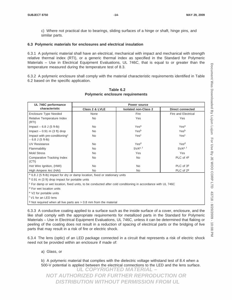
6.3.2 A polymeric enclosure shall comply with the material characteristic requirements identified in Table6.2 based on the specific application.
Table 6.2Polymeric enclosure requirements
UL 746C performancecharacteristic
Power source
Class 2 & LVLE Isolated non-Class 2 Direct connected
Enclosure Type Needed None Fire Fire and Electrical
Relative Temperature Index(RTI)
No Yes Yes
Impact – 6.8 J (5 ft-lb) No Yesa Yesa
Impact – 0.91 m (3 ft) drop No Yesb Yesb
Impact with pre-conditioningc
– 6.8 J (5 ft-lb)No Yesc Yesc
UV Resistance No Yesd Yesd
Flammability No 5VAe, f 5VAe, f
Mold Stress No Yes Yes
Comparative Tracking Index(CTI)
No No PLC of 4g
Hot Wire Ignition, (HWI) No No PLC of 3g
High Ampere Arc (HAI) No No PLC of 2g
a 6.8 J (5 ft-lb) impact for dry or damp location, fixed or stationary unitsb 0.91 m (3 ft) drop impact for portable unitsc For damp or wet location, fixed units, to be conducted after cold conditioning in accordance with UL 746Cd For wet location unitse V2 for portable unitsf V1 for an LED lensg Not required when all live parts are > 0.8 mm from the material
6.3.3 A conductive coating applied to a surface such as the inside surface of a cover, enclosure, and thelike shall comply with the appropriate requirements for metallized parts in the Standard for PolymericMaterials – Use in Electrical Equipment Evaluations, UL 746C, unless it can be determined that flaking orpeeling of the coating does not result in a reduction of spacing of electrical parts or the bridging of liveparts that may result in a risk of fire or electric shock.
6.3.4 The lens (optic) of an LED package connected in a circuit that represents a risk of electric shockneed not be provided within an enclosure if made of:
a) Glass, or
b) A polymeric material that complies with the dielectric voltage withstand test of 8.4 when a500-V potential is applied between the electrical connections to the LED and the lens surface.
MAY 29, 2009SUBJECT 8750 -14-

Do
cum
ent W
as Do
wn
load
ed B
y Lu
jun
Lu
jun
Fo
r Use B
y JE W
OO
CO
RP
LT
D 43718 : 8/20/2009 - 10:08 P
M
UL COPYRIGHTED MATERIAL –NOT AUTHORIZED FOR FURTHER REPRODUCTION OR
DISTRIBUTION WITHOUT PERMISSION FROM UL
6.3.5 The lens (optic) of an LED package connected in a circuit that represents a risk of fire need not beprovided within an enclosure if made of a material having a flammability rating as noted in footnote f ofTable 6.2.
6.4 Enclosure openings
6.4.1 Other than for supply connections, open holes shall not be permitted in any surface of a fire orelectrical enclosure.
Exception: An open hole is permitted in an enclosure intended for installation on or over an outlet boxwhen the outlet box will serve to complete the enclosure.
6.4.2 Open holes shall be permitted for units not intended for installation in a concealed space. Line ofsight to open core and coil components shall be louvered or baffled.
6.5 Conductor protection
6.5.1 Conductors that pass over edges or through openings in metal shall be secured from contacting theedges or be protected from cutting and abrasion. For sheet metal less than 1.1 mm (0.042 in) thick,protection shall be provided by one of the following methods:
a) Rolling the edge of the metal not less than 120 degrees,
b) A bushing or grommet of a material other than rubber at least 1.2 mm (0.047 in) thick, or
c) Glass sleeving at least 0.25 mm (0.010 in) thick.
6.6 Strain relief
6.6.1 For any accessible conductor operating above Class 2 or LVLE limits, a strain relief and cord pushback means shall be provided that complies with the cord strain pushback relief test requirements of 8.8,where cord or lead wire displacement could result in:
a) Subjecting the supply cord or lead to mechanical damage,
b) Exposing the supply cord or lead to a temperature higher than that for which it is rated,
c) Reducing spacing (such as to a metal strain-relief clamp) below the minimum requiredvalues, or
d) Damage to internal connections or components.
Exception: A conductor embedded in an epoxy potting compound inside the enclosure at the cordentrance is considered to be provided with the necessary strain relief.
MAY 29, 2009SUBJECT 8750 -15-

Do
cum
ent W
as Do
wn
load
ed B
y Lu
jun
Lu
jun
Fo
r Use B
y JE W
OO
CO
RP
LT
D 43718 : 8/20/2009 - 10:08 P
M
UL COPYRIGHTED MATERIAL –NOT AUTHORIZED FOR FURTHER REPRODUCTION OR
DISTRIBUTION WITHOUT PERMISSION FROM UL
6.7 Potting compound
6.7.1 Potting compound shall not leak, drip, or be released from a unit while under condition of testing,and shall not exceed its Relative Thermal Index (RTI) during the temperature test of 8.3.
6.7.2 Asphalt potting compound shall remain at least 15°C (27°F) below its softening point as determinedby the Standard Test Methods for Softening Point of Resins Derived from Naval Stores by Ring-and-BallApparatus, ASTM E28.
7 Electrical Construction
7.1 General
7.1.1 A unit intended to be used in an application identified by one of the standards specified in 1.3 shallcomply with the electrical construction requirements of that standard. If an end-use application is notspecified or identified, or if a particular construction feature is not covered by the identified standard, theunit shall comply with the electrical construction requirements of this section.
7.1.2 A current-carrying part shall be silver, copper, a copper alloy, plated iron or steel, stainless steel, orother corrosion-resistant alloys acceptable for the application.
7.1.3 An uninsulated live part shall be secured so that it does not turn or shift in position if such motionresults in a reduction of spacings below the minimum acceptable values.
7.1.4 Friction between surfaces is not acceptable as a means to prevent shifting or turning of a live partbut a lock washer is acceptable.
7.2 Accessibility
7.2.1 A live part that is a risk of electric shock shall be located so it is inaccessible to contact using thearticulate probe shown in Figure 7.1, applying a force not exceeding 4.45 N (1 lbf).
This is generated text for figtxt.
MAY 29, 2009SUBJECT 8750 -16-

Do
cum
ent W
as Do
wn
load
ed B
y Lu
jun
Lu
jun
Fo
r Use B
y JE W
OO
CO
RP
LT
D 43718 : 8/20/2009 - 10:08 P
M
UL COPYRIGHTED MATERIAL –NOT AUTHORIZED FOR FURTHER REPRODUCTION OR
DISTRIBUTION WITHOUT PERMISSION FROM UL
Figure 7.1Articulate probe with web stop
MAY 29, 2009SUBJECT 8750 -17-

Do
cum
ent W
as Do
wn
load
ed B
y Lu
jun
Lu
jun
Fo
r Use B
y JE W
OO
CO
RP
LT
D 43718 : 8/20/2009 - 10:08 P
M
UL COPYRIGHTED MATERIAL –NOT AUTHORIZED FOR FURTHER REPRODUCTION OR
DISTRIBUTION WITHOUT PERMISSION FROM UL
7.2.2 A part that can be removed without using a tool is to be removed when determining accessibility tothe probe.
7.2.3 An insulating barrier used to prevent access to live parts shall not be less than 0.71 mm (0.028 in)thick.
7.2.4 An insulating barrier used in conjunction with not less than half the required spacing through air ispermitted to be less than 0.71 mm (0.028 in) thick, but not less than 0.33 mm (0.013 in) thick if the barrieror liner is of insulating material that is:
a) Resistant to moisture,
b) Of acceptable mechanical strength if exposed or otherwise likely to be subjected tomechanical damage,
c) Reliably held in place, and
d) Located so that it is not adversely affected by operation of the device – particularly arcing.
7.2.5 An insulating barrier in the secondary circuit where the potential is not more than 50 V is permittedto be less than 0.71 mm (0.028 in) thick but not less than 0.25 mm (0.010 in) thick if it is:
a) Resistant to moisture,
b) Of acceptable mechanical strength if exposed or otherwise likely to be subjected tomechanical damage, and
c) Reliably held in place.
7.2.6 An insulating barrier is permitted to have a thickness less than 0.71 mm (0.028 in) thick if separatelyevaluated as an internal barrier in accordance with the Standard for Polymeric Materials – Use inElectrical Equipment Evaluations, UL 746C, and found to have insulating characteristics equivalent to 0.71mm (0.028 in) thick vulcanized fiber.
7.3 Internal wiring
7.3.1 Internal wiring shall consist of insulated conductors having the mechanical strength, dielectricvoltage withstand properties and ampacity for the application.
7.3.2 Each splice and connection shall be mechanically secured, shall provide reliable electrical contact,and shall be provided with insulation at least equivalent to that of the voltage involved unless acceptablepermanent spacing is maintained between the splice and all other uninsulated current-carrying parts atdifferent potentials and non-current-carrying metal parts.
7.3.3 The electrical and mechanical connection between a conductor and any circuitry operating aboveClass 2 or LVLE limits shall be contained within an enclosure and be inaccessible in accordance with 7.2.
MAY 29, 2009SUBJECT 8750 -18-

Do
cum
ent W
as Do
wn
load
ed B
y Lu
jun
Lu
jun
Fo
r Use B
y JE W
OO
CO
RP
LT
D 43718 : 8/20/2009 - 10:08 P
M
UL COPYRIGHTED MATERIAL –NOT AUTHORIZED FOR FURTHER REPRODUCTION OR
DISTRIBUTION WITHOUT PERMISSION FROM UL
7.3.4 Soldered connections shall be mechanically secured before soldering.
Exception No. 1: A wave-solder connection to a metal-clad printed-circuit board is considered acceptablewithout any further mechanical security.
Exception No. 2: A solder connection that is covered after soldering with two-part epoxy is considered tobe mechanically secure.
Exception No. 3: A conductor passed through a hole on the board and soldered on the opposite side isconsidered mechanically secure.
Exception No. 4: Surface Mount Device (SMD) components and small components without integral leadsdo not need to be mechanically secured to the printed wiring board before soldering.
Exception No. 5: The connection of a wire held rigidly in place without the use of solder so as to precludeany movement at the point of electrical connection is considered mechanically secure.
Exception No. 6: A soldered connection supplied by a Class 2 or LVLE source does not require additionalmechanical securement if detachment will not reduce spacings of electrical parts below the applicablerequired spacings of 7.8.
7.3.5 Conductors shall be minimum 18 AWG (0.82 mm2), except as specified in 7.3.6 and 7.3.7, and shallbe rated for the voltage, current, temperature, and conditions of service for normal operation.
7.3.6 Conductors of a size smaller than 18 AWG (0.82 mm2) are permitted under the following conditions:
a) Where completely enclosed,
b) Where not subject to movement under normal use, and
c) In the secondary of a transformer or in a circuit containing only solid-state devices.
7.3.7 Conductors of a size smaller than 24 AWG (0.21 mm2) are permitted when, in addition to theconditions of 7.3.6, the conductors are in Class 2 or LVLE circuits only and are separated from all othernon-Class 2 or LVLE wiring by a barrier.
MAY 29, 2009SUBJECT 8750 -19-

Do
cum
ent W
as Do
wn
load
ed B
y Lu
jun
Lu
jun
Fo
r Use B
y JE W
OO
CO
RP
LT
D 43718 : 8/20/2009 - 10:08 P
M
UL COPYRIGHTED MATERIAL –NOT AUTHORIZED FOR FURTHER REPRODUCTION OR
DISTRIBUTION WITHOUT PERMISSION FROM UL
7.4 Supply and load connections
7.4.1 General
7.4.1.1 Input and output wiring shall comply with the requirements for internal wiring as specified in 7.3in addition to the applicable requirements in this section.
7.4.1.2 Power limited circuit wiring that is intended to be external to a unit and intended to be routedwithin a building structure shall be rated CL2 or CL3 in accordance with the Standard for Power-LimitedCircuit Cables, UL 13.
7.4.2 Permanently-connected units
7.4.2.1 Conduit connection
7.4.2.1.1 A unit intended to be connected to a branch circuit in accordance with the National ElectricalCode (NEC), ANSI/NFPA 70, shall be provided with either field-wiring leads complying with 7.4.2.2 orfield-wiring terminals complying with 7.4.2.3.
7.4.2.1.2 Connection to a permanent wiring system shall be by providing a means for conduit connection.
7.4.2.1.3 Unthreaded openings for conduit and the area surrounding the opening shall comply with therequirements in Table 7.1.
Table 7.1Dimensions of unthreaded opening for conduit and diameter of the area surrounding the
opening
Nominal trade size ofconduit
Unthreaded opening diameter a On interior of component, minimumunobstructed diameter of flat surface
surrounding conduit opening
in mm (in) mm (in)
1/2 22.2 (0.875) 28.09 (1.11)
3/4 28.2 (1.109) 34.04 (1.34)
1 34.9 (1.375) 42.85 (1.69)
1-1/4 44.0 (1.734) 55.07 (7.10)a A plus tolerance of 0.81 mm (0.032 in) and a minus tolerance of 0.38 mm (0.015 in) applies to the knockout diameter.Knockout diameters are to be measured other than at points where a tab attaches the knockout.
7.4.2.1.4 A threaded opening for conduit shall comply with Table 7.2. When tapped all the way through,the opening shall have at least 3.5 but no more than 5 threads and comply with the minimum unobstructeddiameter of flat surface in Table 7.1 to accommodate the conduit bushing. When not tapped all the waythrough, the opening shall have at least 5 threads.
MAY 29, 2009SUBJECT 8750 -20-

Do
cum
ent W
as Do
wn
load
ed B
y Lu
jun
Lu
jun
Fo
r Use B
y JE W
OO
CO
RP
LT
D 43718 : 8/20/2009 - 10:08 P
M
UL COPYRIGHTED MATERIAL –NOT AUTHORIZED FOR FURTHER REPRODUCTION OR
DISTRIBUTION WITHOUT PERMISSION FROM UL
Table 7.2Throat diameters for conduit openings
Nominal trade size ofconduit
Minimum throat diameter Maximum throat diameter
in mm (in) mm (in)
1/2 13.4 (0.528) 15.8 (0.622)
3/4 17.7 (0.697) 20.8 (0.819)
1 22.4 (0.882) 26.7 (1.051)
1-1/4 29.7 (1.169) 35.1 (1.382)
7.4.2.1.5 A unit provided with a means of conduit connection shall be shipped with provision to close allbut one of the conduit openings.
7.4.2.1.6 Unless provided with a reliably separated wiring compartment, an opening provided for thepurpose of making field connections to a branch circuit supply, shall be located greater than 152 mm (6in) from the following:
a) Uninsulated live parts,
b) Low voltage circuitry,
c) Heat producing components,
d) Moving parts, and
e) Any electrical or mechanical component not specifically identified above that could result inan increased risk of fire or risk of shock.
7.4.2.1.7 The area adjacent to an opening where branch circuit supply connections are to be made in thefield and which has components located within 152 mm (6 in) of the opening shall be enclosed within awiring compartment having a volume of at least 98 cm3 (6 in3).
7.4.2.1.8 A field-wiring compartment intended for connection of a wiring system shall be attached to theunit in a manner that will prevent it from turning.
7.4.2.1.9 An outlet box, terminal box, wiring compartment, or the like in which connections to the unit willbe made in the field shall be free from any sharp edge, including screw threads, a burr, a fin, a movingpart, or the like, that may abrade the insulation on conductors or otherwise damage the wiring.
7.4.2.1.10 The minimum volume of an integral field-wiring compartment for branch circuit connectionsshall be determined using Table 7.3. All conductors entering or leaving the compartment shall be includedin the calculation; uninsulated grounding or bonding conductors integral to the unit are not to be included.Field wiring shall assume size 12 AWG (1.64 mm2) conductors unless the ampacity of the unit requireslarger conductors.
MAY 29, 2009SUBJECT 8750 -21-

Do
cum
ent W
as Do
wn
load
ed B
y Lu
jun
Lu
jun
Fo
r Use B
y JE W
OO
CO
RP
LT
D 43718 : 8/20/2009 - 10:08 P
M
UL COPYRIGHTED MATERIAL –NOT AUTHORIZED FOR FURTHER REPRODUCTION OR
DISTRIBUTION WITHOUT PERMISSION FROM UL
Table 7.3Determination of minimum wiring compartment volume
Wire size Conductor volume
AWG cm 3 (in3)
18 8.2 (0.5)
16 9.8 (0.6)
14 12.3 (0.75)
12 16.4 (1.0)
10 27.9 (1.7)
7.4.2.3 Field-wiring leads
7.4.2.2.1 A field-wiring lead shall be no smaller than 18 AWG (0.82 mm2).
7.4.2.2.2 The free length of a field-wiring lead shall be 15.2 cm (6 in) or more. Where a wiringcompartment is provided, the free length is measured from the point of entry of the lead into the wiringcompartment to the free end.
7.4.2.2.3 The insulation of a lead intended for the connection of a grounded conductor (common orneutral) shall be white or gray throughout its length.
7.4.2.2.4 The insulation of a lead intended for the connection of an ungrounded (hot) conductor shall beany color other than white, gray, green, or green with yellow stripe.
7.4.2.2.5 A lead intended for the connection of a grounding conductor shall be bare (no insulation) orgreen, or green with yellow stripe.
7.4.2.2 Field-wiring terminals
7.4.2.3.1 A pressure wire type terminal or a wire binding screw shall be of the type suitable for field wiring.
7.4.2.3.2 A terminal intended for connection of a grounded conductor of an ac supply shall be of metalsubstantially white or silver in color or be marked with the words “NEUTRAL”, “N”, “W” or “White”. No otherterminal shall be substantially white or silver in color.
7.4.2.3.3 A terminal intended for connection of a grounding conductor shall have a green colored head,or the area directly adjacent to the terminal shall be marked with a grounding symbol or abbreviation, asfollows: G or GR or GRD or GND or GRND or GROUND or the symbol (IEC Publication 417, Symbol5019).
7.4.2.3.4 A terminal intended for connection of a dc supply where polarity of the supply connection isrequired shall be marked with the symbols “−“ and “+” on or immediately adjacent to the supply terminals.
7.4.2.3.5 Where dislocation of a secured lead wire can result in a risk of electric shock or a reduction ofrequired spacings, a terminal plate tapped for a wire-binding screw or stud shall be of brass or othernonferrous metal, or plated steel, not less than 0.76 mm (0.030 in) thick, and shall provide not less thantwo full threads in the metal for the binding screw.
Exception No. 1: Two full threads are not required if a lesser number of threads results in a secureconnection in which the threads do not strip when subjected to the tests and requirements of the securityof output terminals test of 8.9.
MAY 29, 2009SUBJECT 8750 -22-

Do
cum
ent W
as Do
wn
load
ed B
y Lu
jun
Lu
jun
Fo
r Use B
y JE W
OO
CO
RP
LT
D 43718 : 8/20/2009 - 10:08 P
M
UL COPYRIGHTED MATERIAL –NOT AUTHORIZED FOR FURTHER REPRODUCTION OR
DISTRIBUTION WITHOUT PERMISSION FROM UL
Exception No. 2: A plate may be less than 0.76 mm (0.030 in) thick if the tapped threads have acceptablemechanical strength as determined by the security of output terminals test of 8.9.
7.4.2.3.6 A wire-binding screw or terminal stud shall not be smaller than 3.5 mm diameter (No. 6) andshall not have more than 32 threads per 25.4 mm (1 in). The screw or stud shall be of brass, brass alloy,or plated iron or steel.
7.4.2.3.7 Terminal studs shall be prevented from turning by means other than friction between mountingsurfaces. The acceptability of a lock washer or similar means to prevent turning shall be determined bythe security of output terminals test of 8.9.
7.4.2.4 Push-in terminals
7.4.2.4.1 A push-in wiring terminal for connection of supply leads shall only allow for the termination ofthe branch circuit conductor supplying the power source, and not provide for additional connections,unless the push-in wiring terminal has been evaluated to handle full branch circuit current.
7.4.2.4.2 The temperature rise of a push-in wire terminal shall not exceed 30°C during the temperaturetest of 8.3.
7.4.2.4.3 A unit that employs push-in terminals shall be marked in accordance with 9.3.1.
7.4.3 Cord-connected and direct plug-in units
7.4.3.1 A unit not intended to be permanently connected to a branch circuit source of supply shall beprovided with either:
a) A cord-connected or direct plug-in power supply, with an output cord for mating with the unit,or
b) A power supply cord and integral polarized or grounding-type attachment plug as shown inFigure 7.2.
This is generated text for figtxt.
MAY 29, 2009SUBJECT 8750 -23-

Do
cum
ent W
as Do
wn
load
ed B
y Lu
jun
Lu
jun
Fo
r Use B
y JE W
OO
CO
RP
LT
D 43718 : 8/20/2009 - 10:08 P
M
UL COPYRIGHTED MATERIAL –NOT AUTHORIZED FOR FURTHER REPRODUCTION OR
DISTRIBUTION WITHOUT PERMISSION FROM UL
Figure 7.2Connection to attachment plug
In the figure:
a) The blade to which the green conductor is connected may have a U-shaped or a circular cross section.
b) The identified conductor is the conductor that intended to be grounded.
MAY 29, 2009SUBJECT 8750 -24-

Do
cum
ent W
as Do
wn
load
ed B
y Lu
jun
Lu
jun
Fo
r Use B
y JE W
OO
CO
RP
LT
D 43718 : 8/20/2009 - 10:08 P
M
UL COPYRIGHTED MATERIAL –NOT AUTHORIZED FOR FURTHER REPRODUCTION OR
DISTRIBUTION WITHOUT PERMISSION FROM UL
7.4.3.2 A three-conductor flexible cord with ground shall be provided with conductor identification toidentify grounded and grounding conductors. A jacketed cord such as a SJT type shall have the groundingconductor within the jacket colored green or green with a yellow stripe and the grounded conductor shallbe colored white or gray.
7.4.3.3 A component with no accessible dead-metal parts is not required to be provided with a supplycord of the grounding type, when identified for use in an end-product with no dead metal needing to begrounded or only for use in an end-product such as portable luminaires where under certain usesgrounding is not required.
7.4.3.4 When a two-conductor flexible cord is provided for connection to the source of supply and polarityis required, the conductors shall be connected to a polarized parallel-blade attachment plug with theidentified grounded conductor (neutral) connected to the wider blade. A parallel cord such as Type SPT-2shall have a stripe, ridge, or groove on the exterior of the cord surface of the grounded (neutral) conductorfor identification.
7.4.3.5 A power supply cord shall be minimum 18 AWG (0.82 mm2).
7.4.3.6 The power supply cord provided on a unit designated for dry location only shall be Type SP-2,Type SPE-2, Type SPT-2, or heavier. The power supply cord on a product intended for use in wetlocations shall be additionally rated for outdoor use by a surface marking “W” or “Water Resistant.”
7.4.3.7 A power supply cord shall be minimum 1.5 m (5 ft) in length. The length shall be measured fromthe point where the cord emerges from the unit, after any strain-relief means provided, to the point wherethe cord enters an attachment plug.
7.4.3.8 Where a knot in a flexible power supply cord serves as strain relief, the surface upon which theknot contacts or bears shall not have burrs, fins, sharp edges, and projections that could damage theinsulation on a cord.
7.4.3.9 A power supply cord shall be provided with a bushing at the point where the cord passes throughan opening in a metal enclosure or through a non-rounded opening of a polymeric enclosure. The bushingshall be secured in place and have a smooth, rounded surface against which the cord bears. The bushingshall be nonmetallic if the cord is Type SVT or lighter.
7.4.3.10 The attachment plug of a cord-connected unit shall be configured for a 15- or 20-A branch circuitreceptacle and shall comply with either the requirements in the Standard for Attachment Plugs andReceptacles, UL 498, or the Standard for Cord Sets and Power-Supply Cords, UL 817, or both.
MAY 29, 2009SUBJECT 8750 -25-

Do
cum
ent W
as Do
wn
load
ed B
y Lu
jun
Lu
jun
Fo
r Use B
y JE W
OO
CO
RP
LT
D 43718 : 8/20/2009 - 10:08 P
M
UL COPYRIGHTED MATERIAL –NOT AUTHORIZED FOR FURTHER REPRODUCTION OR
DISTRIBUTION WITHOUT PERMISSION FROM UL
7.4.4 Leads, terminals, and connectors for other than branch circuit connections
7.4.4.1 General
7.4.4.1.1 Input and output leads, terminals and connectors shall be rated for the voltage, current andtemperature involved.
7.4.4.2 Leads
7.4.4.2.1 Input and output leads shall comply with the requirements for internal wiring of 7.3 and extendat least 152 mm (6 in) outside the unit.
7.4.4.3 Output connectors
7.4.4.3.1 A unit with multiple supply or load connections where interconnection could cumulatively exceedClass 2 or LVLE limits shall be provided with polarized connectors that inhibit such interconnection.
7.4.4.3.2 Output connectors mounted on the enclosure and intended for direct connection of accessoriesshall provide a secure connection between mating parts. The connections shall be polarized if the outputis direct current or if multiple outputs are provided.
7.4.4.3.3 Coaxial cable connectors shall not be used for output connections.
7.4.4.4 Insulation-piercing connections
7.4.4.4.1 Units employing insulation-piercing terminals intended for use with flexible cord or strandedconductor wire operating above Class 2 or LVLE limits shall be for factory assembly only.
7.4.4.4.2 Flexible cord and wire for insulation-piercing connections shall be rated minimum 105°C(221°F).
7.4.4.4.3 Units intended for insulation-piercing connections shall be subjected to the insulation-piercingconnection thermal cycling conditioning test of 8.10 and comply with the temperature test of 8.3.
7.5 Separation of circuits
7.5.1 Insulated conductors of different circuits that may contact each other, including wires in a terminalbox or compartment, shall have insulation rated for the highest of the circuit voltages or shall be reliablyseparated a minimum of 6.44 mm (0.25 in).
7.5.2 Where units have field-installed connections for Class 2 or LVLE circuits inside the enclosure wiringcompartment, the minimum 6.44 mm (0.25 in) separation from non-Class 2 or LVLE circuits shall beprovided by means of separate entries for Class 2 or LVLE and non-Class 2 wiring, or the reliable routingof the conductors within the unit, or the effective use of barriers.
7.5.3 Segregation of insulated conductors may be accomplished by clamping, routing, a barrier, orequivalent means that provides reliable separation from insulated or uninsulated live parts of a differentcircuit.
MAY 29, 2009SUBJECT 8750 -26-

Do
cum
ent W
as Do
wn
load
ed B
y Lu
jun
Lu
jun
Fo
r Use B
y JE W
OO
CO
RP
LT
D 43718 : 8/20/2009 - 10:08 P
M
UL COPYRIGHTED MATERIAL –NOT AUTHORIZED FOR FURTHER REPRODUCTION OR
DISTRIBUTION WITHOUT PERMISSION FROM UL
7.6 Insulating materials
7.6.1 Integral parts such as insulating washers and bushings, and bases or supports for mounting of liveparts, shall be of moisture-resistant materials that are not damaged by the temperatures and stresses towhich they are subjected under conditions of actual use.
7.6.2 An insulating material is to be evaluated for the application in accordance with the Standard forPolymeric Materials – Use in Electrical Equipment Evaluations, UL 746C, with respect to:
a) Mechanical strength,
b) Resistance to ignition sources,
c) Dielectric strength,
d) Insulation resistance,
e) Heat-resistant properties in both the aged and unaged conditions,
f) The degree to which it is enclosed,
g) Resistance to moisture if the unit is other than rated for dry locations, and
h) Any other features affecting the risk of fire and electric shock.
Exception: Materials, such as mica, ceramic, or some molded compounds are usually acceptable for useas the sole support of live parts.
7.7 Printed wiring boards
7.7.1 Printed wiring boards shall meet the following criteria:
a) Conductive traces shall be bonded to the substrate for the minimum conductor width andmaximum unpierced area as required by the Standard for Printed-Wiring Boards, UL 796,
Exception: Printed-wiring boards that are completely encased in potting compound are permittedto exceed their specified minimum conductor width or maximum unpierced area.
b) Temperatures measured in the temperature test of 8.3 shall not exceed the temperaturerating (RTI) of the substrate as determined by the Standard for Polymeric Materials – LongTerm Property Evaluations, UL 746B, and
c) Printed wiring board substrate flammability shall be no less than V-1 in accordance with theStandard for Tests for Flammability of Plastic Materials for Parts in Devices and Appliances, UL94.
Exception: A circuit supplied by a Class 2 or LVLE source need not comply.
MAY 29, 2009SUBJECT 8750 -27-

Do
cum
ent W
as Do
wn
load
ed B
y Lu
jun
Lu
jun
Fo
r Use B
y JE W
OO
CO
RP
LT
D 43718 : 8/20/2009 - 10:08 P
M
UL COPYRIGHTED MATERIAL –NOT AUTHORIZED FOR FURTHER REPRODUCTION OR
DISTRIBUTION WITHOUT PERMISSION FROM UL
7.7.2 Where a conformal coating is used to qualify for spacing reductions per 7.8.2, the conformal coatingshall comply with the requirements in the Standard for Polymeric Materials – Use in Electrical EquipmentEvaluations, UL 746C, and be suitable for use in combination with the printed wiring board.
7.7.3 For components mounted along the edge of a printed wiring board, clearances between uninsulatedparts of opposite polarity and uninsulated live parts and a dead conductive part that is able to be groundedor a metal part exposed to contact by persons are to take into consideration the possible movement ofthe component and the printed wiring board itself. When applying the limits in Tables 7.4 and 7.5, theprinted wiring board is to be positioned, when movement is possible, in the direction that yields thesmallest clearance between the parts in question.
7.8 Electrical spacings
7.8.1 Minimum spacings for field-wired branch circuit supply terminals, between uninsulated live parts ofopposite polarity, between an uninsulated live part and a grounded dead-metal part, and between anuninsulated live part and an accessible dead-metal part shall be in accordance with Table 7.4.
Table 7.4Spacings at field-wiring branch circuit supply terminals
Voltage range Minimum through-air and over-surface spacings between live
and dead-metal parts
Minimum spacings between live parts of opposite polarity
Through air Over surface
V mm (in) mm (in) mm (in)
0 – 125 6.4 (1/4) 3.2 (1/8) 6.4 (1/4)
126 – 300 6.4 (1/4) 6.4 (1/4) 9.5 (3/8)
301 – 600 9.5 (3/8) 9.5 (3/8) 9.5 (3/8)
7.8.2 Minimum spacings for other than field-wired branch circuit supply terminals, between uninsulatedlive parts of opposite polarity, between an uninsulated live part and a grounded dead-metal part, andbetween an uninsulated live part and an accessible dead-metal part shall be in accordance with Table 7.5.
Exception No. 1: Other than for wiring terminals or spacings to a dead-metal conductive enclosure,spacings are permitted to be in accordance with the Standard for Insulation Coordination IncludingClearances and Creepage Distances for Electrical Equipment, UL 840. Overvoltage Category II applies tocircuits directly connected to the supply source. Printed wiring boards are presumed to have a minimumCTI of 100 unless known to be greater.
Exception No. 2: Spacings between uninsulated live parts of different voltage on non-conformal coatedprinted wiring boards, their connectors, and board-mounted electrical components wired on the load sideof line filters or similar voltage peak reduction networks and components, are permitted to be 0.58 mm(0.0230 in) plus 0.005 mm (0.0002 in) per V peak.
Exception No. 3: Encapsulated parts, inherent spacings of discrete components, and circuits supplied bya Class 2 or LVLE source are exempt.
MAY 29, 2009SUBJECT 8750 -28-

Do
cum
ent W
as Do
wn
load
ed B
y Lu
jun
Lu
jun
Fo
r Use B
y JE W
OO
CO
RP
LT
D 43718 : 8/20/2009 - 10:08 P
M
UL COPYRIGHTED MATERIAL –NOT AUTHORIZED FOR FURTHER REPRODUCTION OR
DISTRIBUTION WITHOUT PERMISSION FROM UL
Table 7.5Spacings other than field-wiring branch circuit supply terminals
Potentialinvolved, V rms
Minimum spacings
Between any uninsulated live part and an uninsulated live part ofopposite polarity, uninsulated grounded dead-metal part, or
accessible dead-metal part
Between any uninsulated livepart and the walls of a metal
enclosure
Through air Over surface Shortest distance
mm (in) mm (in) mm (in)
0 – 50 1.6 (1/16)a 1.6 (1/16)a 1.6 (1/16)a
51 – 150 3.2 (1/8)a 6.4 (1/4) 6.4 (1/4)
151 – 300 6.4 (1/4) 9.5 (3/8) 12.7 (1/2)
301 – 600 9.5 (3/8) 12.7 (1/2) 12.7 (1/2)a The spacing between field-wiring terminals of opposite polarity and the spacing between a field-wiring terminal and agrounded dead-metal part shall not be less than 1/4 in.
7.8.3 Enameled and similar film-coated wire is identified as an uninsulated live part.
7.8.4 The spacings between output circuitry and dead metal for a ground-referenced circuit shall bebased on the maximum open-circuit voltage to ground.
7.8.5 Parts subject to movement relative to other parts shall be positioned in their most severe orientationprior to measurement of spacings, unless reliably held in place.
7.9 Circuit components
7.9.1 A fixed resistor, semiconductor, thermistor, Positive Temperature Coefficient (PTC) or NegativeTemperature Coefficient (NTC) resistor, or the like relied upon to limit the output of a unit or otherwiseachieve acceptable performance shall have permanence and stability which does not decrease its limitingcapabilities over time and use. Among the factors considered when evaluating a limiting component arethe cumulative effects of temperature, electrical transients, moisture, and other environmental conditions.
7.9.2 A component that bridges two circuits otherwise required to be isolated from one another shall beone of the following:
a) A capacitor complying with the antenna coupling requirements specified in the Standard forCapacitors and Suppressors for Radio- and Television-Type Appliances, UL 1414, or
b) Two capacitors connected in series, each capacitor individually complying with the dielectricvoltage withstand test of 8.4, or
c) An optical isolator complying with the requirements of the Standard for Optical Isolators, UL1577, with a suitable isolation voltage rating.
MAY 29, 2009SUBJECT 8750 -29-

Do
cum
ent W
as Do
wn
load
ed B
y Lu
jun
Lu
jun
Fo
r Use B
y JE W
OO
CO
RP
LT
D 43718 : 8/20/2009 - 10:08 P
M
UL COPYRIGHTED MATERIAL –NOT AUTHORIZED FOR FURTHER REPRODUCTION OR
DISTRIBUTION WITHOUT PERMISSION FROM UL
7.10 Protective devices
7.10.1 A protective device relied upon for compliance with this standard shall comply with therequirements applicable to that component. Protective devices include eutectic material, fuses, overtemperature and over current protectors, thermal protectors, and similar devices intended to interrupt orlimit the flow of current as a result of overload.
7.10.2 A protective device in a primary circuit shall not be connected in the neutral (grounded) conductorunless the device simultaneously interrupts the grounded and ungrounded supply conductors.
7.10.3 An overcurrent protective device relied upon for construction or performance requirements shall beinaccessible to tampering or shall not be interchangeable with a device having a higher current rating.
7.10.4 The fuse type identification and ampere rating shall be marked in accordance with 9.3.2 on oradjacent to a user serviceable fuse or fuse holder.
7.10.5 A eutectic material link or printed wiring board trace relied upon as an overcurrent protectivedevice shall be conformal coated or potted, and shall comply with the limited short circuit and foil tracecalibration tests specified in the Standard for Fluorescent-Lamp Ballasts, UL 935.
7.11 Coil insulation
7.11.1 General
7.11.1.1 A coil shall be provided with insulation between the coil and any dead-metal part, and betweeneach adjacent pair of windings. Physical insulation material is not required if the spacings requirements ofelectrical spacings of 7.8 are met without any insulation material in place.
Exception: Two or more secondary windings may be considered as a single winding and interposinginsulation is not required if, when interconnected, the windings comply with the performance requirementsfor a single winding.
7.11.1.2 Coil insulation shall either be inherently moisture resistant or treated to render it moistureresistant. Film-coated magnet wire is considered to be moisture resistant.
MAY 29, 2009SUBJECT 8750 -30-

Do
cum
ent W
as Do
wn
load
ed B
y Lu
jun
Lu
jun
Fo
r Use B
y JE W
OO
CO
RP
LT
D 43718 : 8/20/2009 - 10:08 P
M
UL COPYRIGHTED MATERIAL –NOT AUTHORIZED FOR FURTHER REPRODUCTION OR
DISTRIBUTION WITHOUT PERMISSION FROM UL
7.11.2 Insulation for transformers
7.11.2.1 Insulation between uninsulated, primary wires of opposite polarity shall be one of the following:
a) Electrical grade paper, waxed or otherwise treated to resist the absorption of moisture,having a total thickness of not less than 0.305 mm (0.012 in), or
b) Other insulating material having a dielectric breakdown strength of not less than 2500 V inthe thickness used as determined by the tests on insulating materials specified in the Standardfor Class 2 Power Units, UL 1310.
7.11.2.2 Insulation between primary and secondary windings shall be one of the following:
a) Electrical grade paper, waxed or otherwise treated to resist the absorption of moisture,having a total minimum thickness of 0.305 mm (0.012 in),
b) A molded polymeric material such as a coil form or bobbin having a minimum thickness of0.644 mm (0.025 in), or
c) Other than a molded polymeric material and having a dielectric breakdown strength of notless than 2500 V in the thickness used as determined by the tests on insulating materialsspecified in the Standard for Class 2 Power Units, UL 1310.
7.11.2.3 Tape used as insulation in lieu of spacings for a flanged bobbin wound transformer shall providea continuous 0.8-mm (1/32-in) minimum wide bent up edge against the bobbin flanges.
7.11.2.4 A two-flanged, concentrically-wound transformer shall be subjected to the output loading testrequirements of 8.5.3. The test shall be continued for 15 days if the transformer has:
a) The primary winding wound over the secondary winding or the secondary winding woundover the primary winding, and
b) The primary winding insulated from the secondary winding by a layer of insulating materialother than that specified in 7.11.2.1(b).
Exception: The test is not required to be applied for 15 days if the following requirements are met:
a) Multiple layered winding wire is used, which has been evaluated to the requirements formiscellaneous insulating devices and materials of the Standard for Polymeric Materials – ShortTerm Property Evaluations, UL 746A, the Standard for Polymeric Materials – Long TermProperty Evaluations, UL 746B, and the Standard for Polymeric Materials – Use in ElectricalEquipment Evaluations, UL 746C,
b) The primary-to-secondary winding spacings are reliably maintained and comply with Table7.5,
c) The requirements in the Standard for Insulation Coordination Including Clearances andCreepage Distances for Electrical Equipment, UL 840, are reliably maintained for the primary-to-secondary creepage distance, and a Comparative Tracking Index (CTI) rating of 100 for allinsulating material is determined, or
d) Insulated wiring is used which complies with the Standard for Single- and Multi-LayerInsulated Winding Wire, UL 2353.
MAY 29, 2009SUBJECT 8750 -31-

Do
cum
ent W
as Do
wn
load
ed B
y Lu
jun
Lu
jun
Fo
r Use B
y JE W
OO
CO
RP
LT
D 43718 : 8/20/2009 - 10:08 P
M
UL COPYRIGHTED MATERIAL –NOT AUTHORIZED FOR FURTHER REPRODUCTION OR
DISTRIBUTION WITHOUT PERMISSION FROM UL
7.11.2.5 Insulation between the primary winding and the core shall be one of the following:
a) Electrical grade paper, waxed or otherwise treated to resist moisture, having a minimum totalthickness of 0.305 mm (0.012 in),
b) A molded polymeric material such as a coil form or bobbin having a minimum thickness of0.644 mm (0.025 in), or
c) Other than a molded polymeric material and having a dielectric breakdown strength of notless than 2500 V in the thickness used as determined by the tests on insulating materialsspecified in the Standard for Class 2 Power Units, UL 1310.
Exception: Insulation may be reduced or waived between the primary and core when all of the followingconditions are met:
a) The core is of a low electrical conductance material, for example ferrite used in switch-modeproduct,
b) The core is treated as a live and electrically conductive part when judging insulation andspacings between the core and:
i) Accessible metal parts,
ii) The secondary windings, and
iii) Any other output circuitry.
c) In applying (b), the core shall be considered to be at the maximum potential of the primarywinding, and
d) Insulation between secondary windings and core are in accordance with the aboverequirement.
7.11.2.6 Insulation between the primary winding lead connections and a metallic enclosure shall be oneof the following:
a) Electrical grade paper, waxed or otherwise treated to resist the absorption of moisture, notless than 0.305 mm (0.012 in) thick if used in conjunction with an air spacing of no less thanone-half that specified in 7.8,
b) Electrical grade paper, waxed or otherwise treated to resist the absorption of moisturehaving a total thickness of not less than 0.71 mm (0.028 in) when the insulation is in contactwith the enclosure, or
c) Insulation having a dielectric breakdown strength of not less than 2500 V in the thicknessused for (a) and 5000 V in the thickness used for (b) as determined by tests on insulatingmaterials specified in the Standard for Class 2 Power Units, UL 1310.
MAY 29, 2009SUBJECT 8750 -32-
Do
cum
ent W
as Do
wn
load
ed B
y Lu
jun
Lu
jun
Fo
r Use B
y JE W
OO
CO
RP
LT
D 43718 : 8/20/2009 - 10:08 P
M
UL COPYRIGHTED MATERIAL –NOT AUTHORIZED FOR FURTHER REPRODUCTION OR
DISTRIBUTION WITHOUT PERMISSION FROM UL
7.11.2.7 Insulation in accordance with 7.11.2.8 shall be provided between a crossover lead and:
a) The turns of the winding to which it is connected,
b) The adjacent winding,
c) The metallic enclosure, and
d) The core.
7.11.2.8 To comply with 7.11.2.7, insulation shall be one of the following:
a) Electrical grade paper, waxed or otherwise treated to resist the absorption of moisture,having a total thickness of not less than 0.305 mm (0.012 in), or
b) Other insulating material having a dielectric breakdown strength of not less than 2500 V inthe thickness used as determined by the tests on insulating materials specified in the Standardfor Class 2 Power Units, UL 1310.
Exception No. 1: Any type or thickness of insulation, or a through air spacing less than specified in 7.8,between a crossover lead and the winding to which it is connected may be used if the coil withstands thedielectric voltage withstand test of 8.4 with the potential applied between the coil leads and with the coillead cut at the point where it enters the inner layer.
Exception No. 2: This requirement does not apply to insulation between a Class 2 secondary crossoverlead and:
a) The secondary winding to which the crossover lead is connected,
b) The metallic enclosure, and
c) The core.
7.11.2.9 With reference to Exception No. 1 to 7.11.2.8, the magnet coil of a molded bobbin transformerhaving a slot for the crossover or start lead – unspliced at the windings – is acceptable as crossover leadinsulation if:
a) The slots provide a graduated through air spacing to the winding, increasing to the endturns, and
b) The magnet-coil winding withstands the dielectric voltage withstand test of 8.4.
7.11.2.10 Insulation between the primary-lead connections and the adjacent winding, and betweensecondary-lead connections and the primary winding shall be one of the following:
a) Electrical grade paper, waxed or otherwise treated to resist the absorption of moisture,having a total thickness of not less than 0.71 mm (0.028 in), or
b) Other insulating material having a dielectric breakdown strength of not less than 5000 V inthe thickness used as determined by tests on insulating materials specified in the Standard forClass 2 Power Units, UL 1310.
MAY 29, 2009SUBJECT 8750 -33-

Do
cum
ent W
as Do
wn
load
ed B
y Lu
jun
Lu
jun
Fo
r Use B
y JE W
OO
CO
RP
LT
D 43718 : 8/20/2009 - 10:08 P
M
UL COPYRIGHTED MATERIAL –NOT AUTHORIZED FOR FURTHER REPRODUCTION OR
DISTRIBUTION WITHOUT PERMISSION FROM UL
7.12 Class 2 output circuits
7.12.1 When an output is marked or otherwise identified as being Class 2, that output shall comply withthe construction, performance, and marking requirements described in the Standard for Class 2 PowerUnits, UL 1310.
PERFORMANCE
8 Performance Tests
8.1 General
8.1.1 A unit intended to be used in an application identified by one of the standards specified in 1.3 shallcomply with the performance test requirements of that standard. If an end-use application is not specifiedor identified, or if a safety-related aspect of the unit’s performance is not covered by the identifiedstandard, the unit shall comply with the performance requirements of this section.
8.1.2 All electrical measurements, unless otherwise specified, are to be conducted:
a) In a draft-free room,
b) At an ambient temperature of 25 ±5°C (77 ±9°F) unless a higher ambient temperature isspecified by the manufacturer, and
c) With the unit connected to a supply source of nominal frequency that is adjusted to within 5percent of the marked rated voltage.
8.2 Input test
8.2.1 The input current (or wattage, if so rated) of a LED array, module, or package shall not exceed 110percent of the rating of the unit when operated at rated input voltage.
8.2.2 The input current (or wattage, if so rated) of a LED controller or driver shall not exceed 110 percentof the rating when operated at rated input voltage and supplying rated load.
MAY 29, 2009SUBJECT 8750 -34-

Do
cum
ent W
as Do
wn
load
ed B
y Lu
jun
Lu
jun
Fo
r Use B
y JE W
OO
CO
RP
LT
D 43718 : 8/20/2009 - 10:08 P
M
UL COPYRIGHTED MATERIAL –NOT AUTHORIZED FOR FURTHER REPRODUCTION OR
DISTRIBUTION WITHOUT PERMISSION FROM UL
8.3 Temperature test
8.3.1 A unit shall be subjected to a temperature test to determine that the temperatures do not exceedthe limits on the specified components in Table 8.1 during normal operation of the unit. The unit shall bepositioned in an alcove or test oven appropriate for the product and maintained in an ambient temperatureas specified in Table 8.2.
Table 8.1Maximum acceptable temperatures
Materials and components °C °F
A. COMPONENTS
1. Capacitor (other than oil filled) a a
2. Fuses a a
3. Internal wiring a a
4. Potting compound b b
5. Printed-wiring boards a a
B. ELECTRICAL INSULATION
6. Class 105 (A) Insulation systems:
Over surface – thermocouple method 90 194
Average – resistance method (fully potted) 105 221
Average – resistance method (open core and coil) 95 203
Class 130 (B) Insulation systems:
Outer surface – thermocouple method 110 230
Average – resistance method 120 248
Class 155 (F) Insulation systems:
Outer surface – thermocouple method 135 275
Average – resistance method 140 284
Class 180 (H) Insulation systems:
Outer surface – thermocouple method 150 302
Average – resistance method 165 329
7. Vulcanized fiber employed as electrical insulation for other thancoil systems
90 194
C. SURFACES
8. A surface upon which the unit is placed or mounted in service 90 194
9. A non-metallic surface of a direct plug-in or through-cord unit 75 167
10. Interior surface of field-wiring compartment See 8.3.4
a There are no temperatures specified; the manufacturer’s rated temperature of the material or component is to beused.b Unless the material is thermal-setting, the maximum potting-compound temperature, when corrected to a 40°C(104°F) ambient temperature, is 15°C (27°F) less than the softening point of the compound as determined by theStandard Test Methods for Softening Point of Resins Derived from Naval Stores by Ring-and-Ball Apparatus, ASTME28.
MAY 29, 2009SUBJECT 8750 -35-

Do
cum
ent W
as Do
wn
load
ed B
y Lu
jun
Lu
jun
Fo
r Use B
y JE W
OO
CO
RP
LT
D 43718 : 8/20/2009 - 10:08 P
M
UL COPYRIGHTED MATERIAL –NOT AUTHORIZED FOR FURTHER REPRODUCTION OR
DISTRIBUTION WITHOUT PERMISSION FROM UL
Table 8.2Ambient temperature test condition
Device Test chamber Ambient temperature
Remote, through-cord, or direct plug-in Alcove 25°C (77°F)
Used within a luminaire Test oven 40°C (104°F)
8.3.2 A unit integral to a luminaire product shall be tested in accordance with the applicable luminaireproduct standard.
8.3.3 The temperature on any surface inside a terminal or splice compartment when corrected to 25°C(77°F) shall not be more than 60°C (140°F) unless the device is marked maximum 75°C (167°F) ormaximum 90°C (194°F) in accordance with 9.3.3.
8.3.4 A unit for remote applications is to be tested in an ambient air temperature of 25°C (77°F). Atemperature test may be performed at any ambient-air temperature within 20 – 30°C (68 – 86°F) and thevariation from 25°C (77°F) may be added to or subtracted from the observed temperature readings.
8.3.5 The average of two or more thermocouple readings is to be taken for the air temperature within thetest enclosure. Thermocouples as described in 8.3.17 are to be located so that the temperature-sensingportions are 76.2 mm (3 in) from the floor of the test enclosure, and not less than 76.2 mm (3 in) from thenearest wall.
8.3.6 The test is to continue until constant temperatures are obtained. A temperature is consideredconstant if:
a) The test has been running for at least 3 hours, and
b) Three successive readings, taken at 15-minute intervals, are within 1°C (1.8°F) of oneanother and are still not rising.
8.3.7 For all tests in which a direct plug-in unit is to be energized from a source of supply, the unit is tobe operated from an outlet representing the following constructions:
a) Duplex receptacle outlet with nonmetallic faceplate,
b) Receptacle mounted on a nonmetallic outlet box, not more than 196 cm3 (12 in3) in volume,and
c) Outlet box mounted in a vertical wall section approximately 100 mm (3-1/2 in) thick withplywood or gypsum wallboard surfaces and loosely filled with fiberglass or equivalent thermalinsulation.
8.3.8 A unit intended to be used inside of a luminaire shall be supported in a test oven with its mountingsurface down and 76 mm (3 in) above the base of the enclosure in a central position on two 76 mm (3 in)wooden or ceramic cleats. To determine the temperature produced on the device surface, thermocouplesshall be attached to the case in the areas of major heat sources. Temperatures on the device case shallbe determined by means of thermocouples, and in the coils by the rise-of-resistance method.
MAY 29, 2009SUBJECT 8750 -36-

Do
cum
ent W
as Do
wn
load
ed B
y Lu
jun
Lu
jun
Fo
r Use B
y JE W
OO
CO
RP
LT
D 43718 : 8/20/2009 - 10:08 P
M
UL COPYRIGHTED MATERIAL –NOT AUTHORIZED FOR FURTHER REPRODUCTION OR
DISTRIBUTION WITHOUT PERMISSION FROM UL
8.3.9 For a unit with potting it would be necessary to apply thermocouples to interior components prior topotting.
8.3.10 A thermocouple junction and the adjacent thermocouple lead wire are to be securely held inthermal contact with the surface of the material of which the temperature is being measured. In mostcases, adequate thermal contact will result from securely taping or cementing the thermocouple in place;but, if a metal surface is involved, brazing or soldering the thermocouple to the metal may be necessary.
8.3.11 It may be necessary to test a modified sample, with additional lead wires that are extended, so thatthe temperature of each coil of a device may be measured by the resistance method.
8.3.12 The following explanation pertains to coil insulation temperatures. The insulation systemtemperature (class) is also the internal hot spot temperature limit. The average coil temperature, obtainedby the change of resistance method, is the average of the entire coil from internal hot spots to the cooler,outer surface; hence, the average limit is lower than the internal hot spot, or system limit. Thethermocouple measurement method gives the temperature of the cooler, outer surface; hence, the outersurface limit is lower than the average limit. In end-product applications, the thermocouple measurementmethod is primarily for convenience. At the point on the surface of a device where the temperature isaffected by another source of heat, the temperature may exceed the value given in Table 8.1 provided theaverage temperature is not exceeded.
8.3.13 The temperature on a coil may be measured by the thermocouple method or determined by thechange-of-resistance method (comparing the resistance of the winding at the temperature to be measuredwith its resistance at a known temperature) using the formula specified below.
8.3.14 The temperature of a winding is to be calculated by the following formula:
in which:
TH is the temperature of the coil in degrees C at the end of the test,
RH is the resistance of the coil, in ohms, at the end of the test,
RC is the resistance of the coil, in ohms, at the beginning of the test,
TC is the temperature of the coil in degrees C at the beginning of the test when RC ismeasured,
k is 234.5 for copper or 225.0 for electrical conductor grade (EC) aluminum. Values of theconstant for other grades must be determined,
TAT is the ambient target temperature, normally 25 degrees C, unless the device is being testedfor a higher ambient rating, then TAT would be 40, 55, 65, etc. degrees C, and
MAY 29, 2009SUBJECT 8750 -37-

Do
cum
ent W
as Do
wn
load
ed B
y Lu
jun
Lu
jun
Fo
r Use B
y JE W
OO
CO
RP
LT
D 43718 : 8/20/2009 - 10:08 P
M
UL COPYRIGHTED MATERIAL –NOT AUTHORIZED FOR FURTHER REPRODUCTION OR
DISTRIBUTION WITHOUT PERMISSION FROM UL
TA is the measured ambient temperature in degrees C at the end of the test when RH ismeasured.
8.3.15 As it is generally necessary to de-energize the winding before measuring RH, the value of RH atshutdown is determined by taking several resistance measurements at short intervals, beginning asquickly as possible after the instant of shutdown. A curve plotted showing the resistance values as afunction of time may then be extrapolated to give a value of RH at shutdown.
8.3.16 If a manual method is used to collect the data, generally the values of resistance are to be takenover a 30 second period, 5 seconds apart. The extrapolated value (to the time of power shutdown) can bedetermined by a graphical computer spreadsheet application. If a computer spreadsheet application isused, the trend-line equation can be from the best fit of a linear, polynomial, or exponent regression. If acomputer automated (and quicker) method is used to collect the data, the values of resistance can betaken as permitted by the equipment. The extrapolated value (to the time of power shutdown) can bedetermined by a linear regression.
8.3.17 The junction of the thermocouple is to be firmly secured with the point on the surface on which thetemperature is to be measured. The thermocouple is to consist of wires not larger than 24 AWG (0.21mm2) and not smaller than 30 AWG (0.05 mm2). Thermocouples consisting of 30 AWG (0.05 mm2) ironand constantan (Type J) wires, are to be used whenever a referee temperature measurement bythermocouples is necessary. Thermocouples consisting of chromel-alumel (Type K) or copper-constantan(Type T) wires may be used if it is determined that high frequency ballast operation results in eddy currentheating of iron and constantan thermocouples.
8.4 Dielectric voltage withstand test
8.4.1 The unit shall withstand for one minute, without breakdown, the test potential specified in Table 8.3,using the test equipment specified in 8.4.2 where V is the maximum AC (rms) voltage between the partsunder test. If there is excess capacitive leakage current, the capacitors are permitted to be removed orthe test may be conducted using a DC potential at 1.414 times the AC potential.
Table 8.3Dielectric voltage withstand potential
Applied potential Circuit location
2V + 1000
Between primary circuits or secondary circuits operating at greater than 70 V peakand accessible dead conductive parts
Between the primary and secondary of a transformer
Between PWB traces or other parts operating at different potentials
500 VBetween a secondary circuit operating at no more than 70 V peak and accessibledead conductive parts
8.4.2 The dielectric withstand test equipment shall employ a transformer of 500-VA or larger capacity andhave a variable output voltage that is essentially sinusoidal or continuous direct current. The appliedpotential is to be increased from zero at a substantially uniform rate until the required test level is reached,and is to be held at that level for 1 minute.
Exception: A 500-VA or larger capacity transformer is not required if the transformer is provided with avoltmeter to measure directly the applied output potential.
MAY 29, 2009SUBJECT 8750 -38-

Do
cum
ent W
as Do
wn
load
ed B
y Lu
jun
Lu
jun
Fo
r Use B
y JE W
OO
CO
RP
LT
D 43718 : 8/20/2009 - 10:08 P
M
UL COPYRIGHTED MATERIAL –NOT AUTHORIZED FOR FURTHER REPRODUCTION OR
DISTRIBUTION WITHOUT PERMISSION FROM UL
8.5 Abnormal tests
8.5.1 General
8.5.1.1 Each test in this section is to be conducted on a separate sample unless all parties agree thatmore than one test be conducted on the same sample.
8.5.1.2 During each test, the grounding means, if provided, is to be connected to ground through a 3-Anon-time delay fuse, and the unit is to be draped with a double layer of cheesecloth conforming to theoutline of the unit. The unit is to be energized at rated input voltage and frequency. The supply circuit isto be connected in series with a 20 A fuse (time delay type), of which the characteristics are such that thefuse does not open in less than 12 s when carrying 40 A.
8.5.1.3 After ultimate results have been obtained for each test, the sample shall be permitted to cool toroom temperature and the dielectric voltage withstand test of 8.4 shall be repeated.
8.5.1.4 A risk of fire or electric shock is considered to exist with any of the following results:
a) Opening of the ground fuse,
b) Charring of the cheesecloth,
c) Emission of flame or molten material from the unit,
d) Ignition or dripping of a compound from the unit,
e) Exposure of live parts that pose a risk of electric shock under the requirements foraccessibility of 7.2, or
f) Breakdown during the subsequent dielectric voltage withstand test.
8.5.2 Component failure test
8.5.2.1 A unit shall not exhibit a risk of fire or electric shock when a simulated short circuit is imposed onelectrolytic capacitors or semiconductor devices.
Exception No. 1: Circuits in which maximum power levels have been determined to not exceed 50 W neednot be evaluated for component failure.
Exception No. 2: Devices supplied by a Class 2 or LVLE source need not be subject to this test.
8.5.2.2 Each electrolytic capacitor and semiconductor device is to be short circuited, one at a time (onefault per test). Each test shall continue until either the unit is no longer operable, or until conditions areobviously stable (as determined by no visual changes or detectable thermal increase) for at least 30minutes.
MAY 29, 2009SUBJECT 8750 -39-

Do
cum
ent W
as Do
wn
load
ed B
y Lu
jun
Lu
jun
Fo
r Use B
y JE W
OO
CO
RP
LT
D 43718 : 8/20/2009 - 10:08 P
M
UL COPYRIGHTED MATERIAL –NOT AUTHORIZED FOR FURTHER REPRODUCTION OR
DISTRIBUTION WITHOUT PERMISSION FROM UL
8.5.3 Output loading test
8.5.3.1 An LED driver or controller module shall not exhibit a risk of fire or electric shock when subjectedto the following tests.
8.5.3.2 During the tests of 8.5.3.4 and 8.5.3.5, a circuit protector provided as part of the unit is to remainin the circuit, and a user replaceable fuse is to be replaced by the largest fuse the fuseholder will accept.A manually reset protector is to be operated for 10 cycles and the protector contacts shall be operativeupon completion of the test. If an automatic reset protector is provided, or the input current is a value otherthan zero, the test is to be continued for:
a) 7 hours, or
b) 15 days if required in accordance with 7.11.2.4.
8.5.3.3 For units with more than one output, the remaining outputs are to be open circuited or loaded torated conditions, whichever results in a more severe operating condition.
8.5.3.4 Each output is to be short-circuited in turn. The temperature on the enclosure shall not exceed90°C (194°F).
Exception: A temperature of 150°C (302°F) is acceptable if the unit permanently opens within 1 hourafter initiation of the test.
8.5.3.5 Each output is to be overloaded in turn. Each overload condition is to be conducted with theoutput loaded to a current (IL) equal to the rated current (IR) plus X percent of the difference between themaximum obtainable output current (Imax) and the rated output current (IR). In the tests, the values of Xare to be 100, 75, 50, 25, 20, 15, 10, and 5, in that order. If a load current results in continuous operation,further tests need not be conducted. For each test, a variable resistance load is to be adjusted to therequired value and readjusted, if necessary, one minute after application of the source of supply.
Exception: The alternate test method of 8.5.4 may be used for units that employ a:
a) Thermal link complying with the Standard for Thermal-Links – Requirements and ApplicationGuide, UL 60691, or
b) Fuse complying with the Standard for Low-Voltage Fuses – Part 14: Supplemental Fuses,UL 248-14.
MAY 29, 2009SUBJECT 8750 -40-

Do
cum
ent W
as Do
wn
load
ed B
y Lu
jun
Lu
jun
Fo
r Use B
y JE W
OO
CO
RP
LT
D 43718 : 8/20/2009 - 10:08 P
M
UL COPYRIGHTED MATERIAL –NOT AUTHORIZED FOR FURTHER REPRODUCTION OR
DISTRIBUTION WITHOUT PERMISSION FROM UL
8.5.4 Output loading – alternate method
8.5.4.1 With reference to the Exception to 8.5.3.5, if the output short circuit test of 8.5.3.4 results inopening of a thermal link or fuse, the alternate method of 8.5.4.2 or 8.5.4.3 may be performed in lieu of8.5.3.5.
8.5.4.2 If short circuiting causes opening of a thermal link, the device is to be shunted and athermocouple attached to its body. The load current is to be raised slowly until a temperature equal to therated trip temperature of the device plus 5°C (9°F) is reached. Without further readjustment of the load,the unit is to be operated for the remainder of the specified time length (7 hours or 15 days, as applicable).
8.5.4.3 If short circuiting causes opening of a fuse, the unit is to be tested with a load current that causesthe maximum current to flow in the fused circuit without opening the fuse. The maximum current to bedelivered through the fuse is to be determined by the following formula:
IFC = 1.1 (IFR ) [1 + n(0.02)]
in which:
IFC is the fuse overload current,
IFR is the fuse current rating, and
n is an integer that causes the unit to run such that IFC is able to be maintained at itscontinuous maximum current (7 hours or 15 days, as applicable).
8.5.4.4 When conducting this test, at least two load conditions are to be used; one load condition whereIFC (n = c) results in continuous operation, and one load condition where IFC (n = c + 1) results in openingof the fuse prior to the specified time length (7 hours or 15 days, as applicable). Prior to each test, thesample is to be at room temperature.
8.6 50-Watt point power measurement test
8.6.1 To determine the point beyond which any circuit is unable to deliver more than 50 W of availablepower, a wattmeter and an adjustable external load resistor are to be arranged as illustrated in Figure 8.1.Power limitation is permitted to be accomplished either by the inherent design of the circuit (per 8.6.2), bythe opening of a circuit component (per 8.6.3), or by the opening of a protective device (per 8.6.4).
This is generated text for figtxt.
MAY 29, 2009SUBJECT 8750 -41-

Do
cum
ent W
as Do
wn
load
ed B
y Lu
jun
Lu
jun
Fo
r Use B
y JE W
OO
CO
RP
LT
D 43718 : 8/20/2009 - 10:08 P
M
UL COPYRIGHTED MATERIAL –NOT AUTHORIZED FOR FURTHER REPRODUCTION OR
DISTRIBUTION WITHOUT PERMISSION FROM UL
8.6.2 The external adjustable load resistor is to be initially set for its maximum resistance. The adjustableresistance is then to be reduced gradually to the point of maximum delivery wattage as indicated by apeak reading on the wattmeter.
8.6.3 For a circuit without a designated current limiting device, a circuit component that opens in less than1 minute at any power delivery level less than 50 W and that precludes delivery of 50 W for more thanone minute is considered to effectively limit the circuit output to less than 50 W, if the test can be repeatedtwo additional times on new samples with comparable results.
8.6.4 For a circuit with a designated current limiting device, a closed shorting switch is to be connectedacross the current limiting device and the adjustable resistance is then to be reduced to result in a powerdissipation of exactly 50 W as indicated by the meter. The switch across the current limiting device is thento be opened and the time required for the device to open is to be recorded. A current limiting device thatopens the circuit in less than 1 minute is considered to effectively limit the circuit output to less than 50W.
Figure 8.1Connection of wattmeter
MAY 29, 2009SUBJECT 8750 -42-

Do
cum
ent W
as Do
wn
load
ed B
y Lu
jun
Lu
jun
Fo
r Use B
y JE W
OO
CO
RP
LT
D 43718 : 8/20/2009 - 10:08 P
M
UL COPYRIGHTED MATERIAL –NOT AUTHORIZED FOR FURTHER REPRODUCTION OR
DISTRIBUTION WITHOUT PERMISSION FROM UL
8.7 Leakage current measurement test
8.7.1 A cord-connected unit rated for a nominal 250-V or less supply shall be tested in accordance withthis section. Leakage current shall not be more than:
a) 0.5 MIU for a two-wire cord- and plug-connected unit,
b) 0.5 MIU for a three-wire (including grounding conductor) cord-and plug-connected portableunit, and
c) 0.75 MIU for a three-wire (including grounding conductor) cord- and plug-connectedstationary or fixed unit.
8.7.2 All accessible conductive parts are to be tested for leakage currents. Leakage currents from theseparts are to be measured to the grounded supply conductor individually as well as collectively ifsimultaneously accessible, and from one part to another if they can be readily contacted by one or bothhands of a person at the same time. These measurements do not apply to terminals operating at voltagesthat are not considered to involve a risk of electric shock. If all accessible conductive parts are bondedtogether and connected to the grounding conductor of the power-supply cord, the leakage current can bemeasured between the grounding conductor of the product and the grounded supply conductor.
8.7.3 If a conductive part other than metal is used for an enclosure or part of an enclosure, leakagecurrent is to be measured using a metal foil with an area of 10 by 20 cm (4 by 8 in) in contact with thesurface. If the conductive surface has an area less than 10 by 20 cm (4 by 8 in), the metal foil is to be thesame size as the surface. The metal foil is to conform to the shape of the surface but is not to remain inplace long enough to affect the temperature of the product.
8.7.4 Typical measurement circuits for leakage current with the ground connection open are illustrated inFigure 8.2. The measurement instrument is defined in Figure 8.3. The meter that is actually used for ameasurement need only indicate the same numerical value for a particular measurement as would thedefined instrument; it need not have all the attributes of the defined instrument. Over the frequency range20 Hz to 1 MHz with sinusoidal currents, the performance of the instrument is to be as follows:
a) The measured ratio V1/I1 with sinusoidal voltages is to be as close as feasible to the ratioV1/I1 calculated with the resistance and capacitance values of the measurement instrumentshown in Figure 8.3.
b) The measured ratio V3/I1 with sinusoidal voltages is to be as close as feasible to the ratioV3/I1 calculated with the resistance and capacitance values of the measurement instrumentshown in Figure 8.3. V3 is to be measured by the meter M in the measuring instrument. Thereading of meter M in RMS volts can be converted to MIU by dividing the reading by 500 ohmand then multiplying the quotient by 1,000. The mathematic equivalent is to simply multiply theRMS voltage reading by 2.
This is generated text for figtxt.
MAY 29, 2009SUBJECT 8750 -43-

Do
cum
ent W
as Do
wn
load
ed B
y Lu
jun
Lu
jun
Fo
r Use B
y JE W
OO
CO
RP
LT
D 43718 : 8/20/2009 - 10:08 P
M
UL COPYRIGHTED MATERIAL –NOT AUTHORIZED FOR FURTHER REPRODUCTION OR
DISTRIBUTION WITHOUT PERMISSION FROM UL
Figure 8.2Typical leakage-current measurement circuits
Figure 8.3Measurement instrument for reaction (leakage) current
MAY 29, 2009SUBJECT 8750 -44-

Do
cum
ent W
as Do
wn
load
ed B
y Lu
jun
Lu
jun
Fo
r Use B
y JE W
OO
CO
RP
LT
D 43718 : 8/20/2009 - 10:08 P
M
UL COPYRIGHTED MATERIAL –NOT AUTHORIZED FOR FURTHER REPRODUCTION OR
DISTRIBUTION WITHOUT PERMISSION FROM UL
8.7.5 Unless the measurement instrument is being used to measure leakage current from one part of aunit to another, it is to be connected between accessible parts and the grounded supply conductor.
8.7.6 The sample unit is to be tested for leakage current without prior energization, except as may occuras part of the production-line testing. The supply voltage is to be adjusted to rated voltage. The testsequence is to be as follows, with reference to the Figure 8.2 measurement circuit:
a) With switch S1 open, the unit is to be connected to the measurement circuit. Leakagecurrent is to be measured using both positions of switch S2, and with the unit switching devicesin all their normal operating positions.
b) Switch S1 is then to be closed, energizing the unit. Within 5 seconds, the leakage current isto be measured using both positions of switch S2 and with the unit switching devices in all theirnormal operating positions.
c) Leakage current is to be monitored until thermal stabilization. Both positions of switch S2 areto be used in determining this measurement. Thermal stabilization is to be obtained byoperation as in the normal temperature test.
8.8 Cord strain and pushback relief test
8.8.1 A flexible cord that relies on a strain relief mechanism to limit the stress applied to internalconnections shall be subject to a pulling force of 156 N (35 lbf) applied for 1 min in a directionperpendicular to the plane of entrance into the unit.
8.8.2 Following the test of 8.8.1, the supply cord is to be gripped 25.4 mm (1 in) from the point where itemerges from the product. When a removable bushing that extends further than 25.4 mm (1 in) is present,it is to be removed prior to the test. When the bushing is an integral part of the cord, the test is to becarried out by holding the bushing. The cord is to be pushed back into the product in 25.4-mm (1-in)increments until the cord buckles, or the force applied exceeds 26.7 N (6 lbf).
8.8.3 A lead wire that leaves the enclosure and that relies on a strain relief mechanism to limit the stressapplied to internal connections shall be subject to an applied force of 89 N (20 lbf) or four times the weightof the unit, whichever is less but not less than 22 N (5 lbf), for a period of 1 minute.
8.8.4 The results of 8.8.1 – 8.8.3 shall exhibit no:
a) Movement of the flexible cord more than 1.6 mm (0.063 in),
b) Movement of a lead wire that indicates stress was applied to internal connections,
c) Damage to conductors, connectors, or other components, or loosening of connections insidethe enclosure of the unit, or
d) Exposure of the supply cord or lead wire to temperatures higher than for what they arerated.
MAY 29, 2009SUBJECT 8750 -45-

Do
cum
ent W
as Do
wn
load
ed B
y Lu
jun
Lu
jun
Fo
r Use B
y JE W
OO
CO
RP
LT
D 43718 : 8/20/2009 - 10:08 P
M
UL COPYRIGHTED MATERIAL –NOT AUTHORIZED FOR FURTHER REPRODUCTION OR
DISTRIBUTION WITHOUT PERMISSION FROM UL
8.9 Security of output terminals
8.9.1 A wire-binding terminal having fewer threads or lesser thickness than required by 7.4.2.3.4, or thatrelies upon a lockwasher to prevent turning per 7.4.2.3.6, shall be subject to 100 cycles of conductorconnection and disconnection as described in 8.9.2.
8.9.2 The appropriate wires are to be inserted, and the tightening torque specified in Table 8.4 is to beapplied for 10 seconds to the terminals. The terminals are then to be loosened fully. Following 100 cycles,the terminals shall not turn or exhibit any signs of damage.
Table 8.4Tightening torque for wire-binding screws
Size of terminal screw Wire sizes to be tested Tightening torque
mm No. AWG (mm 2) N•m (lbf•in)
3.5 6 16 – 22 (1.3 – 0.32)a 1.4 (12)
4.0 814 (2.1)b
1.8 (16)16 – 22 (1.3 – 0.32)a
5.0 1010 – 14 (5.3 – 2.1)b
2.3 (20)16 – 22 (1.3 – 0.32)a
a Strandedb Solid wire
8.10 Insulation-piercing connection thermal cycling test
8.10.1 Six units shall be assembled to conductors of the size and type for which they are intended. Thetemperature of the insulation-piercing terminal connections shall be monitored continuously for sevenhours while carrying the maximum rated load. The units shall then be subject to 180 cycles at a rate of3-1/2 hours on and 1/2 hour off (the off-cycle time may be extended for the convenience of measurement),while continuing to monitor the temperatures of the insulation-piercing terminal connections. After the lastcycle, the units shall be energized for a period of seven hours, while still monitoring temperatures.
8.10.2 Temperatures of the insulation-piercing terminal connections on each LED unit at the end of thetest shall not be more than 30°C (54°F) higher than the temperatures measured on the same unit afterthe initial seven hours of operation. At no point during the testing shall the temperature of anyinsulation-piercing terminal connection exceed 90°C (194°F).
MAY 29, 2009SUBJECT 8750 -46-

Do
cum
ent W
as Do
wn
load
ed B
y Lu
jun
Lu
jun
Fo
r Use B
y JE W
OO
CO
RP
LT
D 43718 : 8/20/2009 - 10:08 P
M
UL COPYRIGHTED MATERIAL –NOT AUTHORIZED FOR FURTHER REPRODUCTION OR
DISTRIBUTION WITHOUT PERMISSION FROM UL
8.11 Adhesive support test
8.11.1 An adhesive relied upon to secure a part to another part shall have sufficient strength to withstanda pulling force equal to five times the weight of the supported part after the conditioning described in8.11.2.
8.11.2 The adhesive secured parts shall be conditioned at 23°C (73.4°F) for 48 hours. They shall then beplaced in an air-circulating oven at the temperature and for the time specified by Table 8.5. The adhesiverating temperature shall be based on results from the temperature test of 8.3; the associated conditioningtime shall be by mutual agreement of the parties.
8.11.3 After conditioning, the sample is to be removed from the oven and allowed to cool to roomtemperature. A separating force shall then be evenly applied for one minute, perpendicular to the primaryaxis of the adhesive joint. The parts shall remain secured together.
Table 8.5Adhesive support oven temperature and time
Adhesive rating, °C Oven temperature, °C
300 h (12.5 d) 720 h (30 d) 1000 h (42 d) 1440 h (60 d)
60 125 115 110 100
75 145 135 125 110
90 160 150 140 130
105 180 170 160 145
130 200 190 180 170
155 220 215 205 195
180 245 235 230 220
200 280 265 255 245
220 295 285 275 265
240 N/A 300 290 280
8.12 Environmental tests
8.12.1 Humidity exposure
8.12.1.1 A unit intended for use in damp or wet locations shall be exposed for 168 hours to moist airhaving a relative humidity of 88 ±2 percent at a temperature of 32.0 ±2.0°C (89.6 ±3.6°F).
8.12.1.2 Following the conditioning period, a unit intended for wet locations is to be tested for waterexposure in accordance with 8.12.2. A unit intended only for damp locations is to be subject to thedielectric voltage withstand test of 8.4.
MAY 29, 2009SUBJECT 8750 -47-

Do
cum
ent W
as Do
wn
load
ed B
y Lu
jun
Lu
jun
Fo
r Use B
y JE W
OO
CO
RP
LT
D 43718 : 8/20/2009 - 10:08 P
M
UL COPYRIGHTED MATERIAL –NOT AUTHORIZED FOR FURTHER REPRODUCTION OR
DISTRIBUTION WITHOUT PERMISSION FROM UL
8.12.2 Water exposure
8.12.2.1 A unit intended for use in wet locations shall be subjected to a simulated rain produced inaccordance with 8.12.2.4 – 8.12.2.6.
8.12.2.2 After the exposure, outer surfaces shall be dried and the dielectric voltage withstand test of 8.4shall be repeated. There shall be no breakdown as a result of the dielectric voltage withstand test.
8.12.2.3 After the dielectric voltage withstand test of 8.4, the unit shall be carefully opened to determineif water entered. There shall be no water in contact with electrical parts, except for components suitablefor the condition.
8.12.2.4 During the test the unit is to be oriented in the position that is most likely to result in the wettingof live parts, or in accordance with orientation markings specifically provided for the purpose.
8.12.2.5 The rain test apparatus shall consist of three spray heads mounted in a water supply pipe rackas shown in Figure 8.4. Spray heads are to be constructed in accordance with the details shown in Figure8.5. The assembly is to be positioned in the focal area of the spray heads so that the greatest quantity ofwater is likely to enter the component. The water pressure is to be maintained at 34.5 kPa (5 psi) at eachspray head.
This is generated text for figtxt.
MAY 29, 2009SUBJECT 8750 -48-

Do
cum
ent W
as Do
wn
load
ed B
y Lu
jun
Lu
jun
Fo
r Use B
y JE W
OO
CO
RP
LT
D 43718 : 8/20/2009 - 10:08 P
M
UL COPYRIGHTED MATERIAL –NOT AUTHORIZED FOR FURTHER REPRODUCTION OR
DISTRIBUTION WITHOUT PERMISSION FROM UL
Figure 8.4Spray head piping
Item mm (in)
A 710 (28)
B 1400 (55)
C 55 (2.25)
D 230 (9)
E 75 (3)
MAY 29, 2009SUBJECT 8750 -49-

Do
cum
ent W
as Do
wn
load
ed B
y Lu
jun
Lu
jun
Fo
r Use B
y JE W
OO
CO
RP
LT
D 43718 : 8/20/2009 - 10:08 P
M
UL COPYRIGHTED MATERIAL –NOT AUTHORIZED FOR FURTHER REPRODUCTION OR
DISTRIBUTION WITHOUT PERMISSION FROM UL
Figure 8.5Spray head assembly
Item mm (in) Item mm (in)
A 31.00 (1.219) M 2.38 (0.094)
B 11.00 (0.438) N 0.80 (0.031)
C 14.00 (0.563) P 14.61 – 14.63 (0.575 –0.576)
D 14.68 –14.73
(0.578 – 0.580) Q 11.51 – 11.53 (0.453 –0.454)
E 0.40 (0.016) R 6.35 (0.250)
F Optional Optional S 0.80 (0.031)
G 1.52 (0.060) T 2.80 (0.110)
H 5.00 (0.196) U 2.50 (0.980)
J 18.30 (0.719) V 16.00 (0.625)
K 3.97 (0.156) W 1.52 (0.060)
L 6.35 (0.250)
MAY 29, 2009SUBJECT 8750 -50-

Do
cum
ent W
as Do
wn
load
ed B
y Lu
jun
Lu
jun
Fo
r Use B
y JE W
OO
CO
RP
LT
D 43718 : 8/20/2009 - 10:08 P
M
UL COPYRIGHTED MATERIAL –NOT AUTHORIZED FOR FURTHER REPRODUCTION OR
DISTRIBUTION WITHOUT PERMISSION FROM UL
8.12.2.6 The assembly shall be subjected to the water spray for a total of 4 hours. During the 4 hours theassembly is to be energized and de-energized in the following sequence:
Test duration, h Test period, h Operational Water
0 – 1.0 1.0 On Off
1.0 – 1.5 0.5 Off On
1.5 – 3.5 2.0 On On
3.5 – 4.0 0.5 Off On
8.13 Mechanical strength tests for metal enclosures
8.13.1 An enclosure part of thickness less than required by Table 6.1 shall withstand the two tests, insequence, described in 8.13.2 and 8.13.3:
a) Without permanent distortion to the extent that spacings are reduced below the valuesspecified in 7.8,
b) Without transient distortion that results in contact with live parts other than those connectedin a Class 2 or LVLE circuit, and
c) Without development of openings that expose parts that involve a risk of electric shock orinjury. Any openings resulting from the test are to be judged under the requirements foraccessibility of 7.2.
8.13.2 The enclosure part is to be subjected to a 111 N (25 lbf) for 1 minute. The force is to be appliedby means of a steel hemisphere 12.7 mm (1/2 in) in diameter.
8.13.3 The enclosure part is to be subjected to an impact of 6.8 J (5 ft-lb). The impact is to be applied bymeans of a smooth, solid, steel sphere 50.8 mm (2 in) in diameter and having 535 g (1.18 lb) mass. Thesphere is to fall freely from rest through a vertical distance of 1.29 m (51 in).
9 Markings
9.1 General
9.1.1 A unit intended to be used in an application identified by one of the standards specified in 1.3 shallcomply with the marking requirements of that standard. If an end-use application is not specified oridentified, or if a construction or performance related marking of the unit is not covered by the identifiedstandard, the unit shall comply with the marking requirements of this section.
9.1.2 A marking shall be legible, with minimum 1.6 mm (0.062 in) lettering and use one or more of thefollowing methods:
a) Lettering on a pressure-sensitive label,
b) Paint stenciled lettering,
c) Ink-stamped machine lettering,
d) Ink-hand-stamped lettering,
e) Indelibly printed lettering,
MAY 29, 2009SUBJECT 8750 -51-

Do
cum
ent W
as Do
wn
load
ed B
y Lu
jun
Lu
jun
Fo
r Use B
y JE W
OO
CO
RP
LT
D 43718 : 8/20/2009 - 10:08 P
M
UL COPYRIGHTED MATERIAL –NOT AUTHORIZED FOR FURTHER REPRODUCTION OR
DISTRIBUTION WITHOUT PERMISSION FROM UL
f) Die-stamped lettering, or
g) Embossed, molded, or cast lettering, raised or recessed a minimum of 0.010 in (0.25 mm) indepth.
9.1.3 Pressure-sensitive labels and nameplates of the permanent type that are secured by adhesive shallcomply with the Standard for Marking and Labeling Systems, UL 969, and be suitable for the mountingsurface material and temperature involved, and the environment to which it will be subjected.
9.2 Identification and ratings
9.2.1 All units shall bear the following markings:
a) Company name,
b) Model designation,
c) Factory identification or code, for any component produced or assembled at more than onefactory, and
d) Date of manufacture.
9.2.2 A power source integrated with a controller or LED array or both shall be provided with markings(a) through (c) below. A power source packaged separately from the controller or LED array or both shallbe provided with markings (a) through (d):
a) Environmental suitability (dry, damp, or wet location),
b) Input voltage,
c) Input current and power factor, or input wattage, and
d) Rated output voltage and current (or wattage).
9.2.3 Each output of a power source or controller intended to supply a Class 2 circuit shall comply with7.12 and be marked “Class 2.”
9.2.4 An LED controller shall be marked with the following:
a) Environmental suitability (dry, damp, or wet location),
b) Input limitations (i.e., Class 2 input only), if applicable,
c) Input voltage,
d) Input current or wattage, and
e) Rated output voltage and current (or wattage).
Additional information, such as maximum number and connection details of controlled LEDs shall also beprovided with a controller. This may be on a separate instruction sheet.
MAY 29, 2009SUBJECT 8750 -52-

Do
cum
ent W
as Do
wn
load
ed B
y Lu
jun
Lu
jun
Fo
r Use B
y JE W
OO
CO
RP
LT
D 43718 : 8/20/2009 - 10:08 P
M
UL COPYRIGHTED MATERIAL –NOT AUTHORIZED FOR FURTHER REPRODUCTION OR
DISTRIBUTION WITHOUT PERMISSION FROM UL
9.2.5 An LED array, module, or package shall be marked with the following:
a) Environmental suitability (dry, damp, or wet location),
b) Input limitations (i.e., Class 2 input only), if applicable,
c) Input voltage, and
d) Rated current or wattage.
9.3 Construction-related markings
9.3.1 A unit that employs push-in terminals shall be provided with installation instructions containing thefollowing information:
a) For releasing the wire from the terminal connection,
b) The intended wire size(s),
c) Whether the terminal is intended for both solid and stranded or just solid wire,
d) The length to strip the insulation from conductors, and
e) The terminal relationship to the internal circuitry.
9.3.2 Where required, a fuse replacement marking shall be provided on or adjacent to the fuseholder, andshall identify the appropriate fuse type and ampere rating.
9.3.3 When the temperature on any surface within a terminal compartment or splice compartmentexceeds 60°C (140°F) during the temperature test of 8.3, a unit shall be marked with the followingstatement or the equivalent, located so that it is readily visible when connections are made: “ForConnections Use Wire Rated for at Least _____,” in which the temperature is to be either 75°C (167°F)or 90°C (194°F) as determined by the temperature test.
MAY 29, 2009SUBJECT 8750 -53-

Do
cum
ent W
as Do
wn
load
ed B
y Lu
jun
Lu
jun
Fo
r Use B
y JE W
OO
CO
RP
LT
D 43718 : 8/20/2009 - 10:08 P
M
UL COPYRIGHTED MATERIAL –NOT AUTHORIZED FOR FURTHER REPRODUCTION OR
DISTRIBUTION WITHOUT PERMISSION FROM UL
APPENDIX A
Standards for Components
Standards under which components of the products covered by this standard are evaluated include thefollowing:
Title of Standard − UL Standard Designation
Attachment Plugs and Receptacles – UL 498Capacitors – UL 810Capacitors and Suppressors for Radio- and Television-Type Appliances – UL 1414Circuit Cables, Power-Limited – UL 13Component Connectors for Use in Data, Signal, Control and Power Applications – UL 1977Cords and Cables, Flexible – UL 62Cord Sets and Power-Supply Cords – UL 817Electrical Quick-Connect Terminals – UL 310Extruded Insulating Tubing – UL 224Fluorescent-Lamp Ballasts – UL 935Fuseholders – UL 512Information Technology Equipment – Safety – Part 1: General Requirements – UL 60950-1Insulation Coordination Including Clearances and Creepage Distances for Electrical Equipment – UL 840Lampholders – UL 496Low Voltage Fuses – Part 14: Supplemental Fuses – UL 248-14Low Voltage Transformers – Part 1: General Requirements – UL 5085-1Low Voltage Transformers – Part 2: General Purpose Transformers – UL 5085-2Low Voltage Transformers – Part 3: Class 2 and Class 3 Transformers – UL 5085-3Marking and Labeling Systems – UL 969Optical Isolators – UL 1577Polymeric Materials – Fabricated Parts – UL 746DPolymeric Materials – Industrial Laminates, Filament Wound Tubing, Vulcanized Fibre, and MaterialsUsed In Printed-Wiring Boards – UL 746EPolymeric Materials – Long Term Property Evaluations – UL 746BPolymeric Materials – Short Term Property Evaluations – UL 746APolymeric Materials – Use in Electrical Equipment Evaluations – UL 746CPower Units Other Than Class 2 – UL 1012Power Units, Class 2 – UL 1310Printed-Wiring Boards – UL 796Protectors for Use in Electrical Equipment, Supplementary – UL 1077Single- and Multi-Layer Insulated Winding Wire – UL 2353Switches for Lighting Control, Nonindustrial Photoelectric – UL 773ASwitches, Special-Use – UL 1054Systems of Insulating Materials – General – UL 1446Temperature-Indicating and -Regulating Equipment – UL 873Terminal Blocks – UL 1059Tests for Flammability of Plastic Materials for Parts in Devices and Appliances – UL 94Thermal-Links – Requirements and Application Guide – UL 60691Thermistor-Type Devices – UL 1434Transformers, Dry-Type General Purpose and Power – UL 1561Transformers and Motor Transformers for Use in Audio-, Radio- and Television-Type Appliances – UL1411
MAY 29, 2009SUBJECT 8750 -54-

Do
cum
ent W
as Do
wn
load
ed B
y Lu
jun
Lu
jun
Fo
r Use B
y JE W
OO
CO
RP
LT
D 43718 : 8/20/2009 - 10:08 P
M
UL COPYRIGHTED MATERIAL –NOT AUTHORIZED FOR FURTHER REPRODUCTION OR
DISTRIBUTION WITHOUT PERMISSION FROM UL
Wire Connectors – UL 486A-486BWires and Cables, Thermoplastic-Insulated – UL 83Wiring Materials, Appliance – UL 758
Copyright © 2009 Underwriters Laboratories Inc.
MAY 29, 2009SUBJECT 8750 -55-

Do
cum
ent W
as Do
wn
load
ed B
y Lu
jun
Lu
jun
Fo
r Use B
y JE W
OO
CO
RP
LT
D 43718 : 8/20/2009 - 10:08 P
M
UL COPYRIGHTED MATERIAL –NOT AUTHORIZED FOR FURTHER REPRODUCTION OR
DISTRIBUTION WITHOUT PERMISSION FROM UL
MAY 29, 2009SUBJECT 8750 -56-
No Text on This Page