UK Protective Marking: UK HPR1000 … · UK Protective Marking: Not Protectively Marked facilities,...
43
Transcript of UK Protective Marking: UK HPR1000 … · UK Protective Marking: Not Protectively Marked facilities,...

UK HPR1000 GDA
Preliminary Safety Report Chapter 14 Probabilistic Safety Assessment
UK Protective Marking: Not Protectively Marked
Rev: 000 Page: 2 / 43
UK Protective Marking: Not Protectively Marked
DISTRIBUTION LIST Recipients Cross Box
GNS Executive
GNS all staff
GNS and BRB all staff
CGN
EDF
Regulators
Public
☒
☒
☒
☒
☐
☐
☒

UK HPR1000 GDA
Preliminary Safety Report Chapter 14 Probabilistic Safety Assessment
UK Protective Marking: Not Protectively Marked
Rev: 000 Page: 3 / 43
UK Protective Marking: Not Protectively Marked
SENSITIVE INFORMATION RECORD
Section Number
Section Title Page Content Category

UK HPR1000 GDA
Preliminary Safety Report Chapter 14 Probabilistic Safety Assessment
UK Protective Marking: Not Protectively Marked
Rev: 000 Page: 4 / 43
UK Protective Marking: Not Protectively Marked
Table of Contents
14.1 List of Abbreviations and Acronyms ................................................ 6
14.2 Introduction ....................................................................................... 8
14.3 HPR1000 (FCG3) PSA Methodology ............................................. 10
14.3.1 Level 1 PSA .................................................................................... 12
14.3.1.1 Plant Faults (Internal Events) Level 1 PSA .................................... 12
14.3.1.2 Internal and External Hazards Level 1 PSA ................................... 17
14.3.1.3 Fuel Route ....................................................................................... 24
14.3.2 Level 2 PSA .................................................................................... 25
14.3.2.1 Plant Faults (Internal Events) Level 2 PSA .................................... 25
14.3.2.2 Internal and External Hazards Level 2 PSA ................................... 28
14.3.2.3 Sub-Chapter Conclusions ............................................................... 28
14.3.3 Level 3 PSA .................................................................................... 28
14.4 HPR1000 (FCG3) PSA Key Findings ............................................. 28
14.4.1 HPR1000 (FCG3) PSA Influence on the HPR1000 (FCG3) Design .
......................................................................................................... 29
14.4.2 HPR1000 (FCG3) PSA Results ...................................................... 29
14.4.2.1 Level 1 PSA Results ....................................................................... 29
14.4.2.2 Level 2 PSA Results ....................................................................... 31
14.5 Development of UK HPR1000 PSA ............................................... 34
14.5.1 Development of the PSA to Enable Direct Comparison with the
Numerical Targets Defined in the ONR SAPs .............................................. 35
14.5.2 Fault Schedule ................................................................................. 36
14.5.3 Fuel Route Operations .................................................................... 36
14.5.4 Seismic PSA .................................................................................... 37
14.5.5 Development of the Level 2 PSA ................................................... 37
14.5.6 Level 3 PSA .................................................................................... 37
14.5.6.1 Requirement .................................................................................... 37
UK HPR1000 GDA
Preliminary Safety Report Chapter 14 Probabilistic Safety Assessment
UK Protective Marking: Not Protectively Marked
Rev: 000 Page: 5 / 43
UK Protective Marking: Not Protectively Marked
14.5.6.2 Overview of Level 3 PSA Method ................................................. 37
14.5.6.3 Information Required to Support Level 3 PSA .............................. 38
14.5.6.4 Potential Software Options for Delivery of a Level 3 PSA ........... 39
14.6 Conclusions arising from the HPR1000 (FCG3) PSA .................... 39
14.6.1 Assessment Criteria ......................................................................... 39
14.6.2 Conclusions ..................................................................................... 40
14.6.2.1 Qualitative Aspect ........................................................................... 40
14.6.2.2 Quantitative Aspect ......................................................................... 40
14.7 PSA Conclusions ............................................................................. 41
14.8 References ....................................................................................... 42

UK HPR1000 GDA
Preliminary Safety Report Chapter 14 Probabilistic Safety Assessment
UK Protective Marking: Not Protectively Marked
Rev: 000 Page: 6 / 43
UK Protective Marking: Not Protectively Marked
14.1 List of Abbreviations and Acronyms
AAD Startup and Shutdown Feedwater System [SSFS]
ALARP As Low As Reasonably Practicable
ASEP Accident Sequence Evaluation Program
ATWS Anticipated Transient Without Scram
BOP Balance of Plant
BSL Basic Safety Level
BSO Basic Safety Objective
CDF Core Damage Frequency
CET Containment Event Tree
DCH Direct Containment Heating
EHR Containment Heat Removal System [CHRS]
FCG Fangchenggang Nuclear Power Plant
FDF Fuel Damage Frequency
GCT Turbine Bypass System [TBS]
GDA Generic Design Assessment
GIS Graphical Information System
HPR1000 Hua-long Pressurized Reactor
HPR1000 (FCG3) Hua-long Pressurized Reactor under construction at Fangchenggang Nuclear Power Plant Unit 3
HRA Human Reliability Analysis
IAEA International Atomic Energy Agency
IE Initiating Event
LPSD Low Power and Shutdown
LRF Large Release Frequency
MCCI Molten Core Concrete Interaction
MSQA Management System and Quality Assurance
ONR Office for Nuclear Regulation
UK HPR1000 GDA
Preliminary Safety Report Chapter 14 Probabilistic Safety Assessment
UK Protective Marking: Not Protectively Marked
Rev: 000 Page: 7 / 43
UK Protective Marking: Not Protectively Marked
PDS Plant Damage State
PHE Public Health England
POS Plant Operating State
PSA Probabilistic Safety Assessment
PWR Pressurized Water Reactor
RHR Residual Heat Removal System
RRI Component Cooling Water System [CCWS]
/ry per reactor year
SAPs Safety Assessment Principles
SEC Essential Service Water System [ESWS]
SF Safety Function
SG Steam Generator
SFIS Spent Fuel Interim Storage
SFP Spent Fuel Pool
SPAR-H Standardized Plant Risk Analysis-Hum an Reliability Analysis
Procedure
SPSA Seismic PSA
SSCs Structures, Systems and Components
UK HPR1000 The UK Version of the Hua-long Pressurized Reactor
System codes (XXX) and system abbreviations (YYY) are provide d for completeness
in the format (XXX [YYY]), e.g. Component Cooling Water System (RRI [CCWS]).

UK HPR1000 GDA
Preliminary Safety Report Chapter 14 Probabilistic Safety Assessment
UK Protective Marking: Not Protectively Marked
Rev: 000 Page: 8 / 43
UK Protective Marking: Not Protectively Marked
14.2 Introduction
This chapter presents information to support understanding that the UK Version of the Hua-long Pressurized Reactor (U K HPR1000) design will be developed in an evolutionary manner, using robust design processes, buildin g on relevant good international practice, to achieve a strong safety and environmental performance. This chapter will dem onstrate that the P robabilistic Safety Assessment (PSA) is used to understand the nuclear safety risk profile, a nd to inform decisions on improvements to the design. Through the course of the licens ing process the PSA will be developed to support the safety analysis that underpins the safety performance of the UK HPR1000.
The PSA that will be developed for the UK HPR1000 supports the following high level objective:
“The design and intended construction and operation of the UK HPR1000 will protect the workers and the public by providing multiple levels of defense to f ulfill the fundamental safety functions”.
This chapter will demonstrate the following:
The PSA is used to understand the nuclear safe ty risk profile, and to infor m decisions on improvements to the design.
The design version of the UK HPR1000 for the Generic Design Assessment (GDA) has not been declared yet. The design wi ll be based on t he version of HPR1000 (FCG3).
During the course of GDA, the PSA for UK HPR1000 will be developed from the Level 1 and Level 2 PS A used in support of the HPR1000 (FCG3) safety analysis into a full scope PSA (Levels 1, 2 and 3), in line with the de sign evolution of the UK HPR1000, to consider all operating modes, and the full range of fault conditions. Since the PSA for the HPR1000 (FCG3) will be th e basis for the eventual PSA for the UK HPR1000, that this basis is sound will need to be demonstrated.
The strategy adopted for this chapter is to take full cognizance of the wor k undertaken for HPR1000 (FCG3), the approach adopted therein and the insights arising therefrom and to use this to demonstrate the intent for UK HPR1000.
In support of the above, the remainder of this chapter is structured to consider:
a) Sub-chapter 14.3 discusses the methodologie s used in the developm ent of the HPR1000 (FCG3) PSA ;
b) Sub-chapter 14.4 presents the key findings arising from the HPR1000 (FCG3) PSA;
c) Sub-chapter 14.5 outlines the req uirements to support developm ent of the UK HPR1000;

UK HPR1000 GDA
Preliminary Safety Report Chapter 14 Probabilistic Safety Assessment
UK Protective Marking: Not Protectively Marked
Rev: 000 Page: 9 / 43
UK Protective Marking: Not Protectively Marked
d) Sub-chapter 14.6 discus ses the ev idence presented to supp ort the claim s outlined above.
The PSA is a key chapter in the presentation of the analysis of nuclear safety. The PSA models reflect, and provide support to, th e design of plant and system s for which associated chapters are presented in the P SR. Additionally, the PSA utilizes information from the activities and p rocesses covered by the chapters summarized in T-14.2-1.
T-14.2-1 Key interfaces between the PSA and other areas of the PSR
Chapter Title Interfaces with the PSA
1 Introduction Presentation of the overall objectives for the PSR.
3 Generic Site Characteristics Presentation of generic site da ta for hazards (e.g. flood, seismic).
4 General Safety and Design Principles
PSA support to validation of Sa fety Measure reliability (with Core Dam age Frequency (CDF) and Lar ge Release Frequency (LRF) targets).
12 Design Basis Conditions Analysis
Presents the Fault Schedule, which can support Level 1 and Level 2 PSA.
13 Design Extension Conditions & Severe Accident Analysis
Presents the beyond design basis analysis, which is an input to Level 2 PSA, covering contributions to containm ent breach frequency.
15 Human Factors Provision of/support to Human Error Probability assessments.
18 External Hazards Definition and characterization of the hazards, to support the hazards elem ents of the PSA.
19 Internal Hazards Definition and characterization of the hazards, to support the hazards elem ents of the PSA.
20 Management System and Quality Assurance (MSQA) & Safety Case Management
Outlines the saf ety case pro cess, and includes the role of the PSA in supporting the analysis of risk le vels in support of the As Low As Reasonably Practicable (ALARP) process.
21 Reactor Chemistry Source term infor mation from chapter 21 will support Level 2 PSA.
22 Radiological Protection The result of Level 3 PSA will be performed to compare with the Targets 7, 8 and 9 of the

UK HPR1000 GDA
Preliminary Safety Report Chapter 14 Probabilistic Safety Assessment
UK Protective Marking: Not Protectively Marked
Rev: 000 Page: 10 / 43
UK Protective Marking: Not Protectively Marked
Chapter Title Interfaces with the PSA
Safety Assessment Principles (SAPs) which are related to the radiation protection.
26 Environment
General site inf ormation including population and m etrological data that supports the environm ental impact assessment could be used to support the PSA Level 3 analysis.
14.3 HPR1000 (FCG3) PSA Methodology
This sub-chapter outlines the scope and m ethods adopted for the various elem ents of the HPR1000 (FCG3) PSA models.
The HPR1000 (FCG3) PSA has been devel oped in acco rdance with internationally accepted practices, a co mprehensive set of refe rences were used to shap e the analysis (T-14.3-1 refers). The principal references used were:
Chinese standards:
a) NB/T 20037.1-2011 - Probabilistic Safety Assessment for Nuclear P ower Plant Applications Part 1: Internal Events Level 1 PSA for Power Operation;
b) NB/T 20037.2-2012 - Probabilistic Safety Assessment for Nuclear Power Plant Applications Part 2: Internal Events Level 1 PSA for Low Power and Shutdown states;
c) NB/T 20037.3-2012 - Probabilistic Safety Assessment for Nuclear Power Plant Applications Part 3: Internal Flooding;
d) NB/T 20037.4-2013 - Probabilistic Safety Assessment for Nuclear Power Plant Applications Part 4: Internal Fire;
e) NB/T 20037.5-2013 - Probabilistic Safety Assessment for Nuclear Power Plant Applications Part 5: Seismic.
The above standards are all derived from the US and international standards referenced below.
International technical standards and guidelines:
a) International Atomic Energy Agency (IA EA), Development and Application of Level 1 Probabilistic Safety Assessment for Nuclear Power Plants Specific Safety Guide. IAEA Safety Standards SSG-3. 2010;
b) IAEA, Development and Application of Level 2 PSA for Nuclear P ower Plant. IAEA Safety Standards SSG-4. 2010;
c) NUREG/CR-6850, EPRI/NRC-RES Fire PR A methodology for nuclear power
UK HPR1000 GDA
Preliminary Safety Report Chapter 14 Probabilistic Safety Assessment
UK Protective Marking: Not Protectively Marked
Rev: 000 Page: 11 / 43
UK Protective Marking: Not Protectively Marked
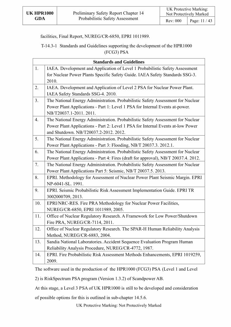
facilities, Final Report, NUREG/CR-6850, EPRI 1011989.
T-14.3-1 Standards and Guidelines supporting the development of the HPR1000 (FCG3) PSA
Standards and Guidelines
1. IAEA. Development and Application of Level 1 Probabilistic Safety Assessment for Nuclear Power Plants Specific Safety Guide. IAEA Safety Standards SSG-3. 2010.
2. IAEA. Development and Application of Level 2 PSA for Nuclear Power Plant. IAEA Safety Standards SSG-4. 2010.
3. The National Energy Administration. Probabilistic Safety Assessment for Nuclear Power Plant Applications - Part 1: Level 1 PSA for Internal Events at-power. NB/T20037.1-2011. 2011.
4. The National Energy Administration. Probabilistic Safety Assessment for Nuclear Power Plant Applications - Part 2: Level 1 PSA for Internal Events at-low Power and Shutdown. NB/T20037.2-2012. 2012.
5. The National Energy Administration. Probabilistic Safety Assessment for Nuclear Power Plant Applications - Part 3: Flooding, NB/T 20037.3. 2012.1.
6. The National Energy Administration. Probabilistic Safety Assessment for Nuclear Power Plant Applications - Part 4: Fires (draft for approval), NB/T 20037.4. 2012.
7. The National Energy Administration. Probabilistic Safety Assessment for Nuclear Power Plant Applications Part 5: Seismic, NB/T 20037.5. 2013.
8. EPRI. Methodology for Assessment of Nuclear Power Plant Seismic Margin. EPRI NP-6041-SL. 1991.
9. EPRI. Seismic Probabilistic Risk Assessment Implementation Guide. EPRI TR 3002000709, 2013.
10. EPRI/NRC-RES. Fire PRA Methodology for Nuclear Power Facilities, NUREG/CR-6850, EPRI 1011989, 2005.
11. Office of Nuclear Regulatory Research. A Framework for Low Power/Shutdown Fire PRA, NUREG/CR-7114, 2011.
12. Office of Nuclear Regulatory Research. The SPAR-H Human Reliability Analysis Method, NUREG/CR-6883, 2004.
13. Sandia National Laboratories. Accident Sequence Evaluation Program Human Reliability Analysis Procedure, NUREG/CR-4772, 1987.
14. EPRI. Fire Probabilistic Risk Assessment Methods Enhancements, EPRI 1019259, 2009.
The software used in the production of the HPR1000 (FCG3) PSA (Level 1 and Level
2) is RiskSpectrum PSA program (Version 1.3.2) of Scandpower AB.
At this stage, a Level 3 PSA of UK HPR1000 is still to be developed and consideration
of possible options for this is outlined in sub-chapter 14.5.6.

UK HPR1000 GDA
Preliminary Safety Report Chapter 14 Probabilistic Safety Assessment
UK Protective Marking: Not Protectively Marked
Rev: 000 Page: 12 / 43
UK Protective Marking: Not Protectively Marked
14.3.1 Level 1 PSA
The HPR1000 (FCG3) Level 1 PSA evaluates core damage risk of the reacto r and the plant operation states include Power operation and Low Power and Shutdown (LPSD) states. The scope of the HPR1000 (FCG3) Level 1 PSA encompasses:
a) Plant Faults (internal events);
b) Hazards (external events):
1) Internal Hazards (internal fire and internal flooding);
2) External Hazards (man-made and natural).
c) The following Fuel Route (Spent Fuel Pool) operations:
1) Short term storage of assemblies in the SFP;
2) Transfer of irradiated fuel between the SFP and the reactor, and vice-versa.
The approach adopted for the HPR1000 (FCG3) PSA is outlined in the remainder of this sub-chapter.
14.3.1.1 Plant Faults (Internal Events) Level 1 PSA
The scope of Plant Fa ults contains Po wer Operation and LP SD. A key dif ference between the approach adopted for the produc tion of LPSD PSA and that adopted for Power Operation is the need to reco gnize a number of different plant operating states (POS). The definition of the different POSs reflect different power plant configurations whose operational parameters are relatively stable and the nature of the risk impact is different from those of other configurations. A total of seven POSs (the defined POSs are only used for PSA analysis) have b een used in the H PR1000 (FCG3) PSA and these are presented in T-14.3-2.
T-14.3-2 Definition of Plant Operating States
POS Name
POSA Power operation
POSB Shutdown condition of Steam Generator (SG) cooling mode
POSC Shutdown condition of Residual Heat Removal System (RHR) cooling mode
POSD Maintenance cold shutdown when manholes are closed
POSE Maintenance cold shutdown when manholes are open
POSF Refueling cold shutdown mode and Reactor completely discharged mode
POSG MID-LOOP1 condition
1 Mid-LOOP is a normal operational state for purification and degasifier service during maintenance cold shutdown.
UK HPR1000 GDA
Preliminary Safety Report Chapter 14 Probabilistic Safety Assessment
UK Protective Marking: Not Protectively Marked
Rev: 000 Page: 13 / 43
UK Protective Marking: Not Protectively Marked
14.3.1.1.1 Power Operation
The internal events PSA undertaken for HPR1000 (FCG3) has been developed in accordance with the methods outlined in the relevant stand ards and for which the key steps can be summarized as follows:
a) Collection of plant information;
b) Identification of Initiating Events (IEs) and estimation of their frequencies;
c) Analysis of accident sequences;
d) Establishment of success criteria;
e) System reliability analysis;
f) Human reliability analysis;
g) Data analysis;
h) Quantification of accident sequences;
i) Uncertainty and sensitivity analysis;
j) Documentation.
The following provides a brief outline of the main process adopted in the production of the HPR1000 (FCG3) PSA and provides concluding remarks on the methods adopted.
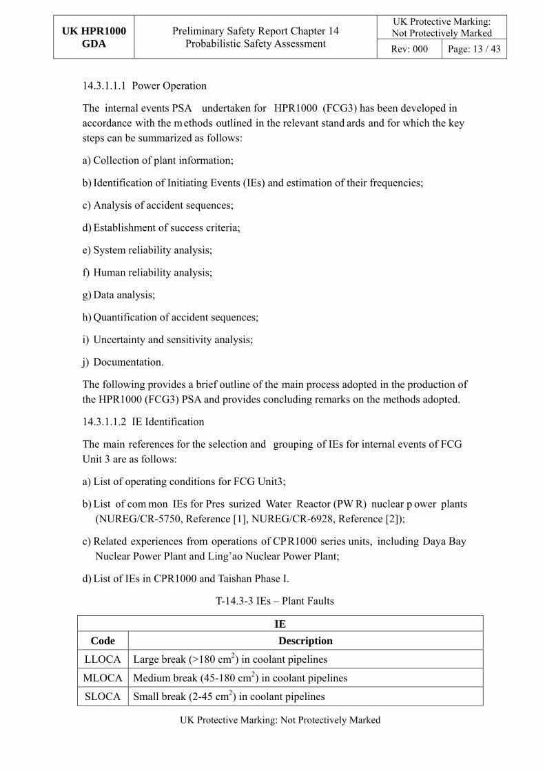
14.3.1.1.2 IE Identification
The main references for the selection and grouping of IEs for internal events of FCG Unit 3 are as follows:
a) List of operating conditions for FCG Unit3;
b) List of com mon IEs for Pres surized Water Reactor (PW R) nuclear p ower plants (NUREG/CR-5750, Reference [1], NUREG/CR-6928, Reference [2]);
c) Related experiences from operations of CPR1000 series units, including Daya Bay Nuclear Power Plant and Ling’ao Nuclear Power Plant;
d) List of IEs in CPR1000 and Taishan Phase I.
T-14.3-3 IEs – Plant Faults
IE
Code Description
LLOCA Large break (>180 cm2) in coolant pipelines
MLOCA Medium break (45-180 cm2) in coolant pipelines
SLOCA Small break (2-45 cm2) in coolant pipelines

UK HPR1000 GDA
Preliminary Safety Report Chapter 14 Probabilistic Safety Assessment
UK Protective Marking: Not Protectively Marked
Rev: 000 Page: 14 / 43
UK Protective Marking: Not Protectively Marked
IE
Code Description
VR Pressure vessel rupture
VLOC Interface LOCA
LOCC Loss of any train of Component Cooling Water System (RRI) [CCWS]
LOMFW Loss of main feedwater
LOOP Loss of offsite power
FLB Break in main feedwater pipe
SLB Break in main steam pipe
SGTR Steam generator tube broken
LODC Loss of direct current
ST Secondary transient
PT Other transients (primary)
DIL Boron dilution
LORHR Loss of RHR
LOAAD Loss of AAD
CP Cold overpressure
14.3.1.1.3 IE Quantification
Each IE frequency was derived from one of the following methods:
a) Reference to the common IE frequency data for PW R nuclear power plant s (NUREG/CR-5750, Reference [1], NUREG/CR-6928, Reference [2], NUREG-1829, Reference [3]);
b) By developing system fault trees. Mainly for those IEs that are closely related to the system design (loss of Residual Heat Re moval (RHR), the loss of the Com ponent Cooling Water System (RRI [ CCWS]) and the loss of Essential Service Water System (SEC [ESWS]), etc.);
c) Data from other plants (Daya Bay Nuclear Power Plant and Taishan Phase 1).
Table T-14.3-3 presents a list of IEs (plant faults) consid ered in the HPR1000 (FCG3) PSA.
14.3.1.1.4 Accident Sequence Analysis
The HPR1000 (FCG3) PSA adopts the small event tree/large fault tree approach. With this approach the inter-dependencies between front-line systems and support systems is addressed within the detail of the supporti ng fault trees and the num ber of Functional Events (nodes) on the event tre es is m uch reduced. That is, only specific SFs are

UK HPR1000 GDA
Preliminary Safety Report Chapter 14 Probabilistic Safety Assessment
UK Protective Marking: Not Protectively Marked
Rev: 000 Page: 15 / 43
UK Protective Marking: Not Protectively Marked
included in the functional event, such as front-line systems or human operations.
Event sequence, event structures and end states are defined for each IE category based on the expected response of mitigation systems. Success criteria have been established to determine the minimum set of trains o r components that will successfully perform an intended function. F or several success cr iterion and time availability for hum an error events, specific thermal and hydraulic calculations have been conducted.
14.3.1.1.5 Success Criterion
The ability of funda mental SFs to prevent core dam age relies on the definition of minimum levels of performance of the supporting safety systems.
The success criterion for each safety system has been defined as the m inimum level of performance required to achieve the SF , taking into account the sp ecific features of each sequence.
Success criteria for Level 1 PSA have been defined for systems that fulfil the following functions:
a) Reactivity control;
b) Core cooling and;
c) Long-term heat removal.
14.3.1.1.6 System Reliability Analysis
Fault Tree Analysis has been used to model all system functions used to mitigate IEs.
The main failure modes considered include:
a) Equipment fault due to hardware fault;
b) System driving f ault due to I &C fault (loss of, or spurious signal) or spurious operation by operator;
c) Power supply fault;
d) Pre-accident human error;
e) Test and maintenance errors that result in the unavailability of the system.
Supporting systems are modeled through the use of a transfer/ transmission gate.
14.3.1.1.7 Human Reliability Analysis
The Human Reliability Analysis (HRA) considered for HPR1000 (FCG3) PSA includes both pre-accident and post-accident HRA.
Pre-accident HRA deals with the latent errors performed during maintenance or testing of components. These errors, if left undiscovered, result in the unavailability of som e
UK HPR1000 GDA
Preliminary Safety Report Chapter 14 Probabilistic Safety Assessment
UK Protective Marking: Not Protectively Marked
Rev: 000 Page: 16 / 43
UK Protective Marking: Not Protectively Marked
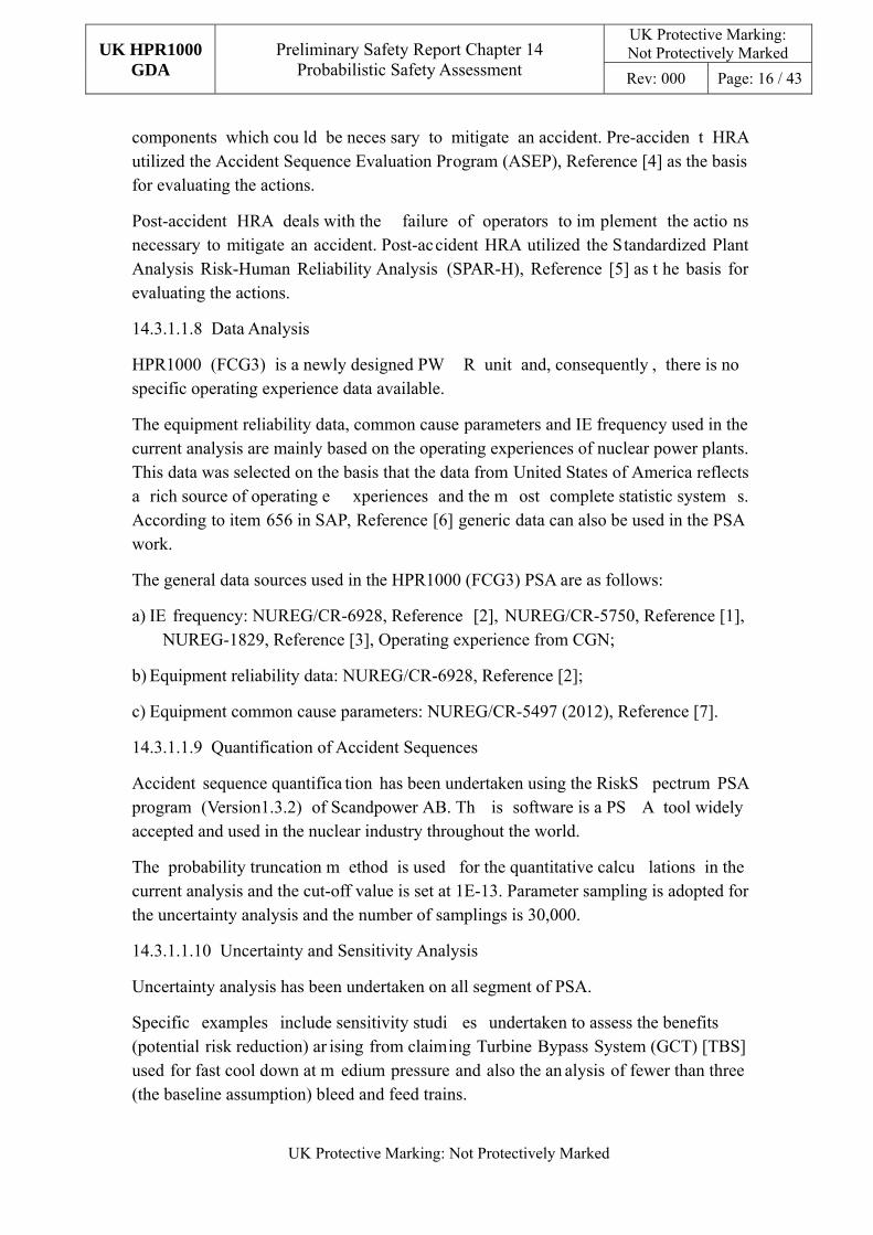
components which cou ld be neces sary to mitigate an accident. Pre-acciden t HRA utilized the Accident Sequence Evaluation Program (ASEP), Reference [4] as the basis for evaluating the actions.
Post-accident HRA deals with the failure of operators to im plement the actio ns necessary to mitigate an accident. Post-accident HRA utilized the Standardized Plant Analysis Risk-Human Reliability Analysis (SPAR-H), Reference [5] as t he basis for evaluating the actions.
14.3.1.1.8 Data Analysis
HPR1000 (FCG3) is a newly designed PW R unit and, consequently , there is no specific operating experience data available.
The equipment reliability data, common cause parameters and IE frequency used in the current analysis are mainly based on the operating experiences of nuclear power plants. This data was selected on the basis that the data from United States of America reflects a rich source of operating e xperiences and the m ost complete statistic system s. According to item 656 in SAP, Reference [6] generic data can also be used in the PSA work.
The general data sources used in the HPR1000 (FCG3) PSA are as follows:
a) IE frequency: NUREG/CR-6928, Reference [2], NUREG/CR-5750, Reference [1], NUREG-1829, Reference [3], Operating experience from CGN;
b) Equipment reliability data: NUREG/CR-6928, Reference [2];
c) Equipment common cause parameters: NUREG/CR-5497 (2012), Reference [7].
14.3.1.1.9 Quantification of Accident Sequences
Accident sequence quantifica tion has been undertaken using the RiskS pectrum PSA program (Version1.3.2) of Scandpower AB. Th is software is a PS A tool widely accepted and used in the nuclear industry throughout the world.
The probability truncation m ethod is used for the quantitative calcu lations in the current analysis and the cut-off value is set at 1E-13. Parameter sampling is adopted for the uncertainty analysis and the number of samplings is 30,000.
14.3.1.1.10 Uncertainty and Sensitivity Analysis
Uncertainty analysis has been undertaken on all segment of PSA.
Specific examples include sensitivity studi es undertaken to assess the benefits (potential risk reduction) ar ising from claiming Turbine Bypass System (GCT) [TBS] used for fast cool down at m edium pressure and also the an alysis of fewer than three (the baseline assumption) bleed and feed trains.

UK HPR1000 GDA
Preliminary Safety Report Chapter 14 Probabilistic Safety Assessment
UK Protective Marking: Not Protectively Marked
Rev: 000 Page: 17 / 43
UK Protective Marking: Not Protectively Marked
14.3.1.1.11 Documentation
The HPR1000 (FCG3) PSA is fully docum ented and much of the inform ation presented in this chapter is a summary of that information.
14.3.1.1.12 Low Power and Shutdown Operation
The development of the Level 1 LP SD PSA for internal events a dopts internationally accepted methods and complies with the requirements on PSA work for nuclear power plants at the design phase as specified in NB/T 20037.2-2012, Reference [8].
The methods used for event sequence analys is, system analysis, hum an reliability analysis, data analysis and techn ical elements such as software platform in the development of Level 1 PSA for internal ev ents in LPSD conditions are the s ame as those used in power condition.
The methods used for selection and groupi ng of IEs in shutdown condition for FCG Unit 3 are the same as those used in power condition. The selection of the IEs modeled in each POS is dependent on the relevance of the at-power IEs to the p lant conditions associated with the POS.
14.3.1.1.13 Sub-Chapter Conclusions
The Level 1 PSA for plant faults has b een developed taking due cognizance of recognized standards and provides a st rong foundation on which the UK HPR1000 PSA can be developed. The key findings arising from the developm ent of the HPR1000 (FCG3) and areas for consideration for enhancem ent to support the development of the UK HPR1000 are iden tified in sub-chapters 14.4 and 14.5 respectively.
14.3.1.2 Internal and External Hazards Level 1 PSA
The method adopted for the hazards PSA is based on the guidelines presented in IAEA SSG-3, Reference [9].
Analysis of internal an d external hazards can be considered to com prise three main steps:
a) Hazard identification to obtain a comprehensive list of external events;
b) Hazard screening to en sure that th e subsequent assessm ent of these hazards is focused on those hazards that are consider ed relevant. This process screens out those hazards that are not applicable or not important;
c) Detailed analysis to characterize the hazards and to reflect the potential threat from these in the PSA models for important/significant hazards or evaluate their risks using other methods.
In addition to consideration of individual hazards, consideration has also been given to
UK HPR1000 GDA
Preliminary Safety Report Chapter 14 Probabilistic Safety Assessment
UK Protective Marking: Not Protectively Marked
Rev: 000 Page: 18 / 43
UK Protective Marking: Not Protectively Marked
co-incident occurrence of hazards.
For considering hazards com bination, the possible combination of hazards should be identified on the basis of the list of individual internal and external hazards.
The general approach used for the identif ication of a realis tic set of combinations of hazards should be bas ed on a system atic check of the depe ndencies between all internal and external hazards.
14.3.1.2.1 Hazard Identification
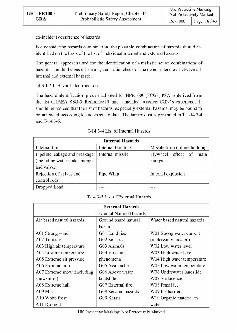
The hazard identification process adopted for HPR1000 (FCG3) PSA is derived fro m the list of IAEA SSG-3, Reference [9] and amended to reflect CGN’ s experience. It should be noticed that the list of hazards, es pecially external hazards, may be bound to be amended according to site specif ic data. The hazards list is presented in T -14.3-4 and T-14.3-5.
T-14.3-4 List of Internal Hazards
Internal Hazards
Internal fire Internal flooding Missile from turbine buildingPipeline leakage and breakage (including water tanks, pumps and valves)
Internal missile Flywheel effect of main pumps
Rejection of valves and control rods
Pipe Whip Internal explosion
Dropped Load --- ---
T-14.3-5 List of External Hazards
External Hazards
External Natural Hazards Air based natural hazards Ground based natural
hazards Water based natural hazards
A01 Strong wind A02 Tornado A03 High air temperature A04 Low air temperature A05 Extreme air pressure A06 Extreme rain A07 Extreme snow (including snowstorm) A08 Extreme hail A09 Mist A10 White frost A11 Drought
G01 Land rise G02 Soil frost G03 Animals G04 Volcanic phenomena G05 Avalanche G06 Above water landslide G07 External fire G08 Seismic hazards G09 Karsts
W01 Strong water current (underwater erosion) W02 Low water level W03 High water level W04 High water temperatureW05 Low water temperature W06 Underwater landslide W07 Surface ice W08 Frazil ice W09 Ice barriers W10 Organic material in water

UK HPR1000 GDA
Preliminary Safety Report Chapter 14 Probabilistic Safety Assessment
UK Protective Marking: Not Protectively Marked
Rev: 000 Page: 19 / 43
UK Protective Marking: Not Protectively Marked
External Hazards
External Natural Hazards A12 Saltstorm A13 Sandstorm A14 Lightning A15 Meteorite
W11 Corrosion (from salt water) W12 Solid or fluid (non-gaseous) impurities from ship release W13 Chemical release to water W14 Tsunami
Man-made External Events (Off-site accidents) M01 Direct impact from ship collision M02 Explosion after transportation accident M03 Chemical release after transportation accident
M04 Explosion outside plant M05 Explosion after pipeline accident M06 Chemical release outside site
M07 Chemical release after pipeline accident M08 Missiles from military activity M09 Excavation work
Man-made External Events (On-site accidents) M10 Direct impact of heavy transportation within site M11 Explosion within the site M12 Explosion after pipeline accident within the site
M13 Chemical release within the site M14 Chemical release after pipeline accident within the site M15 Internal fire spreading from other units on the site
M16 Missiles from other units on the site M17 Internal flood and harsh environment spreading from other units on the site M18 Excavation work within the site area
Other External hazards M19 Satellite crash M20 Aircraft crash
M21 Magnetic disturbance
M22 Failure of a dam upstream of the plant
14.3.1.2.2 Hazard Screening
In accordance with IAEA SSG-3, Reference [9 ], consideration of internal fire and internal flooding is mandatory and a detailed PSA has been produced for these hazards. Currently, for HPR1000 (FCG3) a PSA to cons ider the seismic hazard has not been undertaken and consequently this is not discus sed in this sub-chapter. This omission is recognized in sub-chapter 14.5.
The process adopted for screening of hazards is based on:
a) Characterization of the hazard;
b) Assessment of the impact on the plant;

UK HPR1000 GDA
Preliminary Safety Report Chapter 14 Probabilistic Safety Assessment
UK Protective Marking: Not Protectively Marked
Rev: 000 Page: 20 / 43
UK Protective Marking: Not Protectively Marked
c) Application of the screening criteria (see below) (a different set of criteria were used for co-incident hazards):
1) Criterion 1: The event is of equal or lesser damage potential than the events for which the plant has been designed. This requires an evaluation of plant design bases in o rder to es timate the res istance of plant structures and system s to a particular external hazard;
2) Criterion 2: The event h as a significantly lower mean frequency of occurrence than another event, taking into account the uncertainties in the estimates of both frequencies, and the event could not result in worse consequences than the consequences from the other event;
3) Criterion 3: The event cannot occur close e nough to the plant to af fect it. This criterion must be applied taking into account the range of m agnitudes of the event for the recurrence frequencies of interest;
4) Criterion 4: The event is included in the definition of another event;
5) Criterion 5: The event is slow in deve loping, and it can be dem onstrated that there is suf ficient time to e liminate the source of the th reat or provide an adequate response.
If a hazard meets a single screening criterion it is screened out.
The hazards retained for the HPR1000 (FCG 3) PSA following the application of the screening criteria were:
a) A01 Strong wind;
b) A02 Tornado;
c) W10 Organic material in water;
d) W12 solid or fluid (non-gaseous) impurities from ship release;
e) G08 Seismic hazards (undertak en by specifi c analysis and not consid ered in th e analysis of other external hazards).
The approach used to assess the risk contribution arising from these hazard s is summarized in the next sub-chapter.
14.3.1.2.3 Hazards Modeling
As indicated in the preceding sub -chapter, detailed m odeling was u ndertaken for internal fire and internal flooding and an alternative simple form of modeling was undertaken for the remaining screened in hazards. This sub-chapter outlines the approach undertaken in each case and provides concluding remarks.
a) Fire PSA Modeling

UK HPR1000 GDA
Preliminary Safety Report Chapter 14 Probabilistic Safety Assessment
UK Protective Marking: Not Protectively Marked
Rev: 000 Page: 21 / 43
UK Protective Marking: Not Protectively Marked
The Fire P SA undertaken for HPR1000 (FCG 3) follows the guidance presented in NUREG/CR-6850, Reference [10]. The gene ral ignition source frequency of NUREG/CR-7114, Reference [11] is used for analyzing of LPSD states of Fire PSA. The scope of HPR1000 (FCG3) internal fire PSA includes power state and LPSD states. The key steps adopted for the Fire PSA are as follow:
1) Plant boundary definition and partitioning;
2) Fire PSA components selection;
3) Fire PSA cable selection;
4) Qualitative screening;
5) Fire-induced risk model;
6) Fire ignition frequencies;
7) Quantitative screening;
8) Scoping fire modeling;
9) Detailed circuit failure analysis;
10) Circuit failure mode likelihood analysis;
11) Detailed fire modeling;
12) Post-fire human reliability analysis;
13) Fire risk quantification;
14) Uncertainty and sensitivity analysis;
15) Fire PSA documentation.
Some of the key issues associated with the above are detailed in the following text.
Division of Fire Compartments
This was an iterative process. For areas w ith higher risks and already having specif ic fire zoning schem es, the division of fi re compartments was perform ed by m aking reference to such fire zoning schem es; for areas with low risk s, such as the conventional island and balance of plant (BOP), the division is made with buildings as the basic units. Further sub-division of the initial building zones was undertaken based on the results of initial quantitative assessments.
Identification of Equipment and Cables important for Fire PSA
This was largely based on the criteria outlined in NUREG/CR-6850, Reference [10]. Equipment is identified as important to the PSA its failure would lead to an IE, if it provides a mitigating function or it informs the operator.

UK HPR1000 GDA
Preliminary Safety Report Chapter 14 Probabilistic Safety Assessment
UK Protective Marking: Not Protectively Marked
Rev: 000 Page: 22 / 43
UK Protective Marking: Not Protectively Marked
Cables that support operation of equipment important for fire PSA are also included.
Estimation of Ignition Frequency Calculations and Sources of Data
The derivation of the ignition frequencies fo r fire compartments considers both fixed ignition sources in the com partment and temporary ignition sources. Data for power operation is sourced from NUREG/CR-6850, Reference [ 10] and the data for Shutdown is sourced from NUREG/CR-7114, Reference [11].
Consideration of fire consequences
The modeling of fire impacts is estab lished by considering th e various dif ferent consequences of the fire. These include the IEs caused by the fire, the availability of equipment affected by the fires, the hab itability for operations personnel and the feasibility of measures to mitigate the fire impacts. The approach adopted reflects that outlined in NUREG/CR-6850, Reference [10].
Plant response analysis and its model
The Fire PSA model developed uses the plant faults (internal events) PSA model as the basis and uses the features available in the RiskSpectrum PSA program to reflect the loss/availability of equipment in the zones affected by the f ire (and f ire spread), the feasibility of assumed operator responses and the ef fectiveness of fire m itigation (suppression) measures.
Similarly, this information is app lied to each POS models associated with the LP SD PSA.
b) Internal Flooding PSA Modeling
The Internal Flooding PSA undertaken for HPR1000 (FCG3) follows the Chinese PSA technical standard NB/T 20037.3, Reference [12] for flooding in nuclear power plants the standard (referred to in sub-chapter 14.3). The scope of HPR1000 (FCG3) internal flooding PSA includes power st ate and LPSD states. The key steps adopted for the Internal Flooding PSA are as follows:
1) Flooding areas definition;
2) Identification of flooding sources, floodi ng mechanisms & Structures, Systems and Components (SSC) impacted by flooding;
3) Plant walkdown;
4) Qualitative screening of flooding areas;
5) Characterization of flooding scenarios;
6) Flooding IE frequency quantification;
7) Flooding consequence analysis;

UK HPR1000 GDA
Preliminary Safety Report Chapter 14 Probabilistic Safety Assessment
UK Protective Marking: Not Protectively Marked
Rev: 000 Page: 23 / 43
UK Protective Marking: Not Protectively Marked
8) Flooding mitigation & human reliability analysis;
9) PSA modeling of flooding scenarios;
10) Quantification of flood-induced accident sequences;
11) Documentation of internal flooding PSA.
The approach adopted for the development of Level 1 PSA model for internal flooding can be divided into tw o phases, qualitative analysis and quantitative analysis. In the qualitative phase the plant boundary for the anal ysis is defined and the plant is divided into a number of analysis cells (i.e. floode d areas), information on the equipm ent and flooding sources is ob tained and qualitative screening for the flooded areas is undertaken. In the quantitative phase, de tailed flooding scenario analysis, hum an factors analysis and flooding im pact analysis, etc. is undertaken for the screened in flooded areas, flooding event frequency in each flooded area is established and Level 1 PSA model for internal flooding is developed to derive the quantitative results of CDF caused by internal flooding.
Similarly, this information is applied to each of the POS models associated with the LPSD PSA.
As can be seen from the above text, the underlying principles applied to the development of the Internal Flooding PSA are similar to those applied in the Fire PSA. Consequently, specific details supporting the methods and assumptions are not detailed here.
Similarly to the Fire PSA modeling, the Internal Flooding model us es the plant faults (internal events) PSA model as the basis and uses the features availab le in th e RiskSpectrum PSA program to ref lect the loss/availability of equipment in the zone s affected by the flooding (and floodin g spread) and the feasibility of assumed operator responses.
14.3.1.2.4 Analysis of Other External Hazards
The approach adopted f or the Level 1 PSA of the other screened in hazards can be considered to comprise three major technical elements:
a) Hazard analysis of external hazards;
b) External hazard fragility analysis;
c) External hazard plant response model.
Envelopment analysis is used to analyz e external hazards (s ingle hazards and coincident hazards) with an occurrence frequency below 1.0E-07/ry in a conservativ e manner. The Core Da mage Frequency (CDF) obtained from envelopment analysis is added to the total CDF for external hazards.

UK HPR1000 GDA
Preliminary Safety Report Chapter 14 Probabilistic Safety Assessment
UK Protective Marking: Not Protectively Marked
Rev: 000 Page: 24 / 43
UK Protective Marking: Not Protectively Marked
For those hazards as sessed to occur more fr equently than 1.0E-07/ry, a more detailed analysis was performed.
The following hazard was assessed using the envelopment (bounding) approach:
a) A02 – Tornado.
These requiring more detailed analysis were:
a) A01 - Strong wind;
b) W10 Organic material in water;
c) W12 Solid or fluid (non-gaseous) impurities from ship release.
14.3.1.2.5 Sub-Chapter Conclusions
The Level 1 PSA for hazards (external events) has b een developed taking d ue cognizance of recognized standards and provides a strong foundation on which the UK HPR1000 PSA can be developed. It is recognized that the HPR1000 (FCG3) PSA does not currently consider the seismic haza rd. The key findings arising from the development of the HPR1000 (FCG3) and area s for consideration for enhancem ent to support the development of the UK HPR1000 are identified in sub-chapters 14.4 and 14.5 respectively.
14.3.1.3 Fuel Route
In HPR1000 (FCG3) the risk arising from fuel route operations is represented in the SFP PSA. The SFP PSA calculates the Fuel Damage Frequency (FDF) and covers all types of potential IEs and all associated operational modes. The analysis method of the internal event SFP PSA is similar to internal event Level 1 PSA (i.e. use of event tree and fault trees). The key differences associated with the SFP PSA can be summarized as:
a) The consequences to be assessed are:
1) Fuel Damage;
2) Fuel exposure (loss of cooling, or water).
b) Operating states are defined as:
1) Normal operation;
2) Refuelling operation.
c) Hazards are considered to in duce the IEs re presented in the plan t faults (internal events) SFP PSA;

UK HPR1000 GDA
Preliminary Safety Report Chapter 14 Probabilistic Safety Assessment
UK Protective Marking: Not Protectively Marked
Rev: 000 Page: 25 / 43
UK Protective Marking: Not Protectively Marked
d) In the case of loss of co olant in the SFP, it takes a long time to reach the dangerous water level and such an accident can be prom ptly identified and handled in routine operational inspections.
The guidance presented in NB/T 20037.1-2011 (referred to in sub-chapter 14.3), allows truncation of event sequences and related system models with the selected low enough cut-off value, so as to avoid neglecting th e relevance related to the important minimal cut sets or accident sequences (such as the relevance of personnel errors). Based on the quantitative calculations and com parisons of the PSA model for the SFP, the cut- off value is determined as 1E-13.
14.3.2 Level 2 PSA
The scope of the HPR1000 (FCG3) Level 2 PSA encompasses:
a) Plant states: Power operation and LPSD states;
b) IEs: Plant faults (internal events) and Hazards (external events).
The approach adopted for the HPR1000 (FCG3) PSA is outlined in the remainder of this sub-chapter.
14.3.2.1 Plant Faults (Internal Events) Level 2 PSA
The Level 2 PSA undertaken for HPR1000 (FCG 3) follows the guidance presented in IAEA-SSG-4, Reference [13]. The scope of the HPR1000 (FCG3) Level 2 PSA includes power state and LPSD states. The key steps adopted for the Level 2 PSA are as follow:
a) Investigation of plant information and important designs for severe accident;
b) Classification of plant damage states and estimation of their frequencies;
c) Accident progression and containment capacity analysis;
d) Quantification of the Large Release Frequency:
1) Classification of release categories and estimation of their frequencies;
2) Source term analysis for each release category.
e) Uncertainty and sensitivity analysis;
f) Documentation.
Some of the key issues/elem ents associated with the above are detailed in the following text.
Analysis of Plant Damage States (PDS)
The PDSs are used to link the L evel 1 core damage sequences to the Level 2 Containment Event Trees (CET). Core dam age sequences with similar characteristics

UK HPR1000 GDA
Preliminary Safety Report Chapter 14 Probabilistic Safety Assessment
UK Protective Marking: Not Protectively Marked
Rev: 000 Page: 26 / 43
UK Protective Marking: Not Protectively Marked
are grouped and linked to the appropriate CET by a linking event tree.
The definition of the plant damage states (PDS) used on HPR1000 (FCG3) is based on the PDS presented in IAEA-SSG-4 , Reference [13]. The PDS used are presented in T-14.3-6.
T-14.3-6 HPR1000 (FCG3) Level 2 PSA Plant Damage States
PDS Description
--- Power Operation
LL Large/medium LOCA in POSA
SL Small LOCA in POSA, primary high pressure
IS Interface LOCA in POSA
TR POSA transient accident, primary high pressure
VS POSA main steam/feedwater pipe break accident, primary high pressure
SLD Small LOCA in POSA, primary low pressure
SG Core damage caused by SG tube rupture in POSA, primary high pressure
SS Core damage caused by SLB+SGTR in POSA
VR Large break in pressure vessel (IE)
AT Primary high-pressure core m elt transient caused by Anticipa ted Transient Without Scram (ATWS) accident
TP Primary high-pressure core melt transient caused by station black out accident
--- Shutdown Operation
LL_S Large/medium LOCA in POSB and C
SL_S Small LOCA in POSB, C and D, primary high pressure
IS_S Interface LOCA in shutdown condition
TR_S POSB, C and D transient accident, primary high pressure
VS_S POSB main steam/feedwater pipe break accident, primary high pressure
SLD_S Small LOCA in POSB, C, D and G, primary low pressure
SG_S Core damage caused by SG tube rupture in POSB, primary high pressure
SS_S Core damage caused by SLB+SGTR in POSB
TP_S Primary high-pressure core melt transient caused by station black out in POSB, C, D and G
VO_S Core melt accident in POSE, primary loop already open
VO_S Core melt accident in POSE, primary loop already open
Analysis of severe accident phenomenon
The analyzed severe accident phenomena include:

UK HPR1000 GDA
Preliminary Safety Report Chapter 14 Probabilistic Safety Assessment
UK Protective Marking: Not Protectively Marked
Rev: 000 Page: 27 / 43
UK Protective Marking: Not Protectively Marked
a) Induced break in the primary loop;
b) Early-stage overpressure of containment;
c) Primary water injection (core reflooding);
d) Hydrogen phenomena;
e) Steam explosion;
f) Phenomena after pressure vessel failure (pressure vessel up lift, Direct Containment Heating (DCH), etc.);
g) Late-stage overpressure of containment;
h) Molten Core-Concrete Interaction (MCCI).
Analysis of structural performance of containment
The probability of containment failure with respect to pressure function used in th e HPR1000 (FCG3) PSA is conservatively based on the analysis for CPR1000 units.
Containment event tree
The Containment Event Trees (CETs) have been developed to reflect, chronologically, the following stages of the accident progression:
a) Before pressure vessel failure (TF1);
b) Pressure vessel failure (TF2) and;
c) Long-term stage after pressure vessel failure (TF3).
The mitigation functions presented in the CETs include:
a) Containment isolation. Auto/m anual closure of valves on through-containm ent pipework to ensure that the fission products will not leak out through such paths;
b) Reactor cavity water injection. Manual ac tivation of th e reactor cavity water injection function of the Containment Heat Removal System (EHR [CHRS]);
c) Primary depressurization. Manual activation of the severe accident dedicated valve to avoid high-pressure core melt;
d) Containment heat removal. Realize removal of heat from the containment through the HER [CHRS] system;
e) Passive hydrogen recom biner. To control the hydrogen concentration in the containment in the course of severe accident an d reduce th e threats of hydrogen combustion and explosion on the integrity of containment.
Quantification of functional titles in event tree

UK HPR1000 GDA
Preliminary Safety Report Chapter 14 Probabilistic Safety Assessment
UK Protective Marking: Not Protectively Marked
Rev: 000 Page: 28 / 43
UK Protective Marking: Not Protectively Marked
The methods used f or the asses sment of the f ailure probabilities of the mitigating systems is based on the use of fault trees (the approach adopted is the same as that used for the Level 1 PSA described under the System Reliability Analysis heading in sub-chapter 14.3.1.1). In som e cases (e.g. the probability of cond itional failure of containment) data from NUREG/CR-6595R1, Reference [14] has been used.
Quantification of the Large Release Frequency (LRF)
The quantification of the Level 2 PSA has been undertaken using the RiskSpectrum PSA program (Version 1.3.2) of Scandpower AB.
14.3.2.2 Internal and External Hazards Level 2 PSA
The Level 2 PSA for hazards is d eveloped based on the Level 1 PSA for external events and the scope of analys is is the same as that of Level 1 PSA. The m ain risks in power and shutdown conditions come from:
a) Internal fires;
b) Internal flooding;
c) Other external events.
The PDS attribu tes and characteristic quantities are essentially the sam e as those for internal events. Other aspect s, such as the establishm ent of CET and the m ethods to analyze the accident progresses and phenomena, are the same as those for plant faults (internal events) and are not restated here.
14.3.2.3 Sub-Chapter Conclusions
The Level 2 PSA has been developed taking due cognizance of recognized standards and provides a strong foundation on which th e UK HPR1000 PSA can be developed. However, it is acknowledged that the HPR1000 (FCG3) PSA does not currently include consideration of source terms.
The key findings arising from the development of the HPR1000 (FCG3) and areas for consideration for enhancem ent to suppor t the developm ent of the UK HPR1000 are identified in sub-chapters 14.4 and 14.5 respectively.
14.3.3 Level 3 PSA
Level 3 PSA has not been undertaken for HPR1000 (FCG3). The requirem ent for this in support of the UK HPR1000 is recognized in sub-chapter 14.5.
14.4 HPR1000 (FCG3) PSA Key Findings
This sub-chapter provides a summ ary of the information available from the HPR1000 (FCG3) PSA and considers the following:

UK HPR1000 GDA
Preliminary Safety Report Chapter 14 Probabilistic Safety Assessment
UK Protective Marking: Not Protectively Marked
Rev: 000 Page: 29 / 43
UK Protective Marking: Not Protectively Marked
a) The influence that the HPR1000 ( FCG3) PSA had on the evolution of the HPR1000 (FCG3) design;
b) The results available from the HPR1000 (FCG3) PSA together with a brief discussion of the key contri butors and a summ ary of th e measures identified that have the potential to reduce the assessed risks.
14.4.1 HPR1000 (FCG3) PSA Influence on the HPR1000 (FCG3) Design
The PSA developed through the course of the design of HPR1000 (FCG3), has supported the design evolution through evaluation of:
a) Three series configurations of the safety system;
b) Containment heat removal system;
c) Definition of DEC-A (Design Extension Condition A).
Potential risk reduction m easures were also identified for consideration, for exa mple, provision for manual operation of the reactor cavity water injection valves.
14.4.2 HPR1000 (FCG3) PSA Results
This sub-chapter presents a brief summary of the results availab le from the HPR1000 (FCG3) PSA. Results are presented for:
a) Core Damage Frequency – Level 1 PSA;
b) Large Release Frequency – Level 2 PSA.
14.4.2.1 Level 1 PSA Results
The Level 1 PSA considers Power operations and LPSD operations of the reactor and encompasses both plant faults and a number of internal and external hazards.
The CDF predicted in the HPR 1000 (FCG3) PSA is 6.49E-07/ry 2. The contributions associated with plant faults and internal/external hazards3 are shown in the following table and diagrammatically in F-14.4-1.
T-14.4-1 Core Damage Frequency of Plant Faults and Hazards
Case
Core Damage Frequency (/ry)
Plant Faults Internal/External Hazards
Total
Reactor (all modes) 4.70E-07 1.79E-07 6.49E-07
2 Excluding the contribution of Seismic PSA (SPSA), which is still ongoing as the progress of detailed design in HPR1000 (FCG3). According to a conservative assessment on the SPSA, the total CDF meets, with sufficient margins, the design target of HPR1000 (FCG3) as specified in reference to that required in EUR, Reference [15]. 3 Excluding the SPSA as explained in Note 1.

UK HPR1000 GDA
Preliminary Safety Report Chapter 14 Probabilistic Safety Assessment
UK Protective Marking: Not Protectively Marked
Rev: 000 Page: 30 / 43
UK Protective Marking: Not Protectively Marked
F-14.4-1 CDF % Contribution from Plant Faults and Hazards
The dominant contributors to the C DF are identified in T-14.4-2 and F-14.4-2 shows their % contribution alongside all other contributors.
T-14.4-2 Dominant Contributors (Plant Faults and Hazards) to CDF
No ID Description CDF(/ry)
1. IE_SGTR_A IE SGTR in PO 1.18E-07
2. IE_ATWS IE ATWS in PO 9.89E-08
3. IE_SLOCA_A IE small LOCA in PO 6.78E-08
4. FR(MCR)_A Fire in MCR room in PO 3.63E-08
5. EH_LOCC_A LOCC induced by external hazard in PO 2.91E-08
6. IE_LOCC_A IE LOCC in PO 2.34E-08
7. FR(BSA 24XX SFI)_A
Fire in Saf eguard Building A cable room at +4.9m in PO
2.17E-08
8. IE_RHR IE RHR in PO 2.10E-08

UK HPR1000 GDA
Preliminary Safety Report Chapter 14 Probabilistic Safety Assessment
UK Protective Marking: Not Protectively Marked
Rev: 000 Page: 31 / 43
UK Protective Marking: Not Protectively Marked
F-14.4-2 Dominant contributors to CDF (Plant Faults and Hazards)
As can be s een from the above, the m ost dominant contributions arise from SG tube rupture accident, ATWS accident and loss of coolant accident caused by primary small break (internal events during power opera tion), accounting for 18%, 15% and 10% of the total CDF respectively. In the case of the SG tube ru pture and th e small break LOCA events, their con tribution reflects a known conservatism in the Human Error Probability modeling associated with feed and bleed. The ATWS event is a dom inant contributor essentially as a result of the fact that there are many events that lead to an ATWS event.
Additionally, it can be seen that the distribution of the contributions from all IEs can be considered to be well balanced.
The risk arising from fuel route operations is represented in the Spent Fuel Pool (SFP) PSA. It calculates the fuel dam age frequency (FDF) and covers all types of potential IEs and all associated o perational modes. The result (FDF) of FCG Unit3 is ab out 3.82E-09/ry.
14.4.2.2 Level 2 PSA Results
The Level 2 PSA considers the output fr om the Le vel 1 PSA together with contributions arising from the fuel route operations.
UK HPR1000 GDA
Preliminary Safety Report Chapter 14 Probabilistic Safety Assessment
UK Protective Marking: Not Protectively Marked
Rev: 000 Page: 32 / 43
UK Protective Marking: Not Protectively Marked
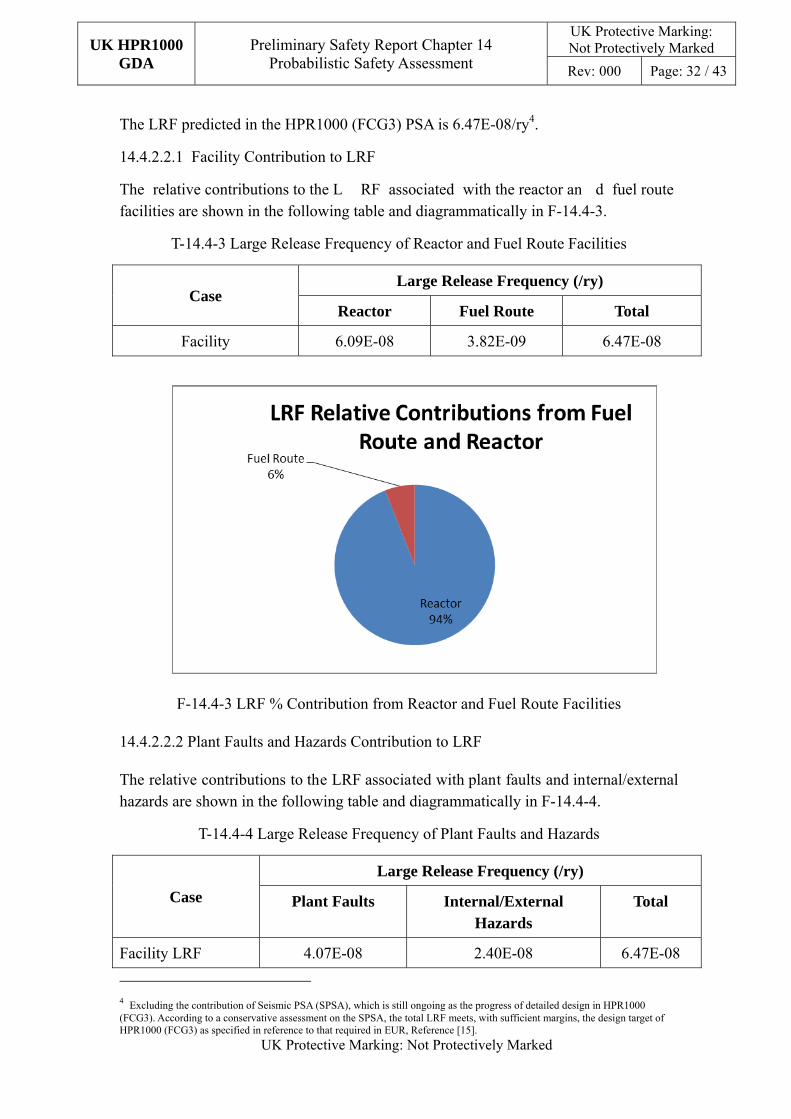
The LRF predicted in the HPR1000 (FCG3) PSA is 6.47E-08/ry4.
14.4.2.2.1 Facility Contribution to LRF
The relative contributions to the L RF associated with the reactor an d fuel route facilities are shown in the following table and diagrammatically in F-14.4-3.
T-14.4-3 Large Release Frequency of Reactor and Fuel Route Facilities
Case Large Release Frequency (/ry)
Reactor Fuel Route Total
Facility 6.09E-08 3.82E-09 6.47E-08
F-14.4-3 LRF % Contribution from Reactor and Fuel Route Facilities
14.4.2.2.2 Plant Faults and Hazards Contribution to LRF
The relative contributions to the LRF associated with plant faults and internal/external hazards are shown in the following table and diagrammatically in F-14.4-4.
T-14.4-4 Large Release Frequency of Plant Faults and Hazards
Case
Large Release Frequency (/ry)
Plant Faults Internal/External Hazards
Total
Facility LRF 4.07E-08 2.40E-08 6.47E-08
4 Excluding the contribution of Seismic PSA (SPSA), which is still ongoing as the progress of detailed design in HPR1000 (FCG3). According to a conservative assessment on the SPSA, the total LRF meets, with sufficient margins, the design target of HPR1000 (FCG3) as specified in reference to that required in EUR, Reference [15].

UK HPR1000 GDA
Preliminary Safety Report Chapter 14 Probabilistic Safety Assessment
UK Protective Marking: Not Protectively Marked
Rev: 000 Page: 33 / 43
UK Protective Marking: Not Protectively Marked
F-14.4-4 LRF % Contribution from Plant Faults and Hazards
14.4.2.2.3 Reactor Contribution to LRF
The reactor’s contribution to the LRF split be tween plant faults and interna l/external hazards are shown in the following table and diagrammatically in F-14.4-5.
T-14.4-5 Large Release Frequency of Plant Faults and Hazards
Case
Large Release Frequency (/ry)
Plant Faults Internal/External Hazards
Total
Reactor (all modes) 3.69E-08 2.40E-08 6.09E-08
F-14.4-5 Reactor contribution to LRF from Plant Faults and Hazards

UK HPR1000 GDA
Preliminary Safety Report Chapter 14 Probabilistic Safety Assessment
UK Protective Marking: Not Protectively Marked
Rev: 000 Page: 34 / 43
UK Protective Marking: Not Protectively Marked
14.4.2.2.4 Fuel Route Contribution to LRF
The fuel route’s contribution to the LRF split between plant faults and internal/external hazards are shown in the following table and diagrammatically in F-14.4-6.
T-14.4-6 Large Release Frequency of Plant Faults and Hazards
Case
Large Release Frequency (/ry)
Plant Faults Internal/External Hazards
Total
Fuel Route 2.95E-09 8.70E-10 3.82E-09
F-14.4-6 Fuel route contribution to LRF showing ratio between Plant Faults and Hazards
While the HPR1000 (FCG3) PSA has been approved by the Chinese regulator , there are a number of areas where further development work has been agreed. This includes consideration of the release catego ries associated with the Level 2 PSA. Consequently it is not possible, at this time, to present a breakdown of the LRF across the release categories.
14.5 Development of UK HPR1000 PSA
This sub-chapter outlines the areas of developm ent required to p roduce a UK HPR1000 PSA that aligns with the regu latory requirements of t he UK. This sub-chapter reflects the delta between the m ethods and infor mation used in the production of the HPR1000 (FCG3) PSA and that required for the UK.
In overall terms, the goal for the UK HPR1000 PSA is, during the course of GDA, to be developed into a full scope PS A (Levels 1, 2 and 3), in line with the design evolution of the UK HPR1000, that considers all operating modes and the full range of
UK HPR1000 GDA
Preliminary Safety Report Chapter 14 Probabilistic Safety Assessment
UK Protective Marking: Not Protectively Marked
Rev: 000 Page: 35 / 43
UK Protective Marking: Not Protectively Marked
fault conditions such that the nuclear safety risks are understood and are ALARP . In supporting of this goal, the assessed risk will be compared with the relevant numerical targets (7, 8 and 9) presented in the Office for Nuclear Regulation (ONR) SAPs.
During the GDA stage, the UK HPR1000 PSA will make some assumptions due to lack of specific informati on. Assumptions m ade regarding the behavior of the UK HPR1000 or its operators will be justified and captured. The sensitivity to some important assumptions will be analyzed.
The UK HPR1000 PSA will be developed based on HPR1000 (FCG3) PSA model. The design differences between UK HPR1000 and HPR1000 (FCG3) will be identified and modified in PSA model to ensure it’s realistic.
14.5.1 Development of the PSA to Enable Direct Comparison with the Numerical Targets Defined in the ONR SAPs
The HPR1000 (FCG3) PSA derives Core Da mage Frequency (Level 1) and Lar ge Release Frequency (Level 2) output.
The UK HPR1000 PSA will be developed thro ugh the course of the GDA process to enable direct comparison with the following numerical targets:
Target 7
Individual risk to people off the site from accidents Target 7
The targets for the individual risk of death to a person off the site, from accidents at the site resulting in exposure to ionising radiation, are:
BSL: 1 x 10⁻⁴ pa BSO: 1 x 10⁻⁶ pa
UK HPR1000 GDA
Preliminary Safety Report Chapter 14 Probabilistic Safety Assessment
UK Protective Marking: Not Protectively Marked
Rev: 000 Page: 36 / 43
UK Protective Marking: Not Protectively Marked
Target 8
Frequency dose targets for accidents on an individual facility – any person off the site
Target 8
The targets for the total predicted frequencies of accidents on an individual facility, which could give doses to a person off the site are:
Effective dose, mSv Total predicted frequency per annum
BSL BSO
0.1 – 1 1 1 x 10⁻²
1 – 10 1 x 10⁻¹ 1 x 10⁻³
10 – 100 1 x 10⁻² 1 x 10⁻⁴
100 – 1000 1 x 10⁻³ 1 x 10⁻⁵
> 1000 1 x 10⁻⁴ 1 x 10⁻⁶
Target 9
Total risk of 100 or more fatalities Target 9
The targets for the total risk of 100 o r more fatalities, either immediate or eventual, fro m accidents at the site resulting in exposure to ionising radiation, are:
BSL: 1 x 10⁻⁵ pa BSO: 1 x 10⁻⁷ pa
14.5.2 Fault Schedule
The process adopted for the identification of IEs for the HPR1000 PSA is based on the use of a standardized list of IEs supplem ented by inform ation from other operating plant (see sub-chapter 14.3.1.1).
The need for a suitable dem onstration that the process used to identify all relevant IEs and that these are presented in the form of a Fault Schedule is recognized in chapter 12. The fault schedule produced in line with the guidance presented in ch apter 12 will support development of the UK HPR1000 PSA.
The need for a fault schedule and the intent with respect to its production is presented in chapter 12 of the PSR.
14.5.3 Fuel Route Operations
The scope of operations considered for the HPR1000 (FCG3) Spent Fuel Pool P SA currently considers storage of spent fuel in the spent fuel pool and transfer of spent fuel to/from the reactor.

UK HPR1000 GDA
Preliminary Safety Report Chapter 14 Probabilistic Safety Assessment
UK Protective Marking: Not Protectively Marked
Rev: 000 Page: 37 / 43
UK Protective Marking: Not Protectively Marked
Expansion of the scope of operations to in clude consideration of Spent Fuel Interim Storage (SFIS) operations will be considered at an app ropriate stage in the licen sing process.
14.5.4 Seismic PSA
While it is noted that the HPR1000 (FCG3) PS A has yet to incorporate the risk arising from a seism ic hazard, this ac tivity is site-sp ecific and will be ass essed at th e appropriate stage in the licensing process.
However, as part of de-risking the overall licensing process, c onsideration will be given to undertaking this work for UK HPR1 000 in an ea rlier stage of the licens ing process. In this event generic site characteristics will be used to allo w the PSA to establish the risk contribution arising from seismic hazards and to allow insights into the hazard withstand capabilities of the UK HPR1000 design.
14.5.5 Development of the Level 2 PSA
The HPR1000 (FCG3) PSA that for ms the basis of the reporting in this chapter generates estimates of the LRF with consideration of release categories or source terms. Associated work is underway to reflect th is information in the HPR1000 (FCG3) PSA and hence will be incorporated into the UK HPR1000 PSA at the appropriate time.
14.5.6 Level 3 PSA
14.5.6.1 Requirement
Level 3 PSA will be developed thro ugh the GDA process to provide evidence that the UK HPR1000 design will be as sessed against the ONR SAPs targets 7 to 9, as well as other ONR expectations related to Level 3 PSA (i.e. Table A1-4 of NS-TAST-GD-030, Reference [16]). Level 3 PSA presents th e consequences of a severe acciden t, or non-core damage radionuclide release at a nuclear facility. These consequences may be probabilistic or deterministic in nature. Probabilistic consequences are the likelihood of long term health consequences to thos e affected by the ra dionuclide release. Deterministic consequences are the estimated immediate h ealth effects and economic effects as a result of the radionuclide release.
14.5.6.2 Overview of Level 3 PSA Method
Level 3 PS A starts wh ere Level 2 PSA ends. Level 2 PS A models the containment response to a severe core accident. The conclusion of a Level 2 PSA is the characterization of the radionuclide releas e including frequencie s of the release, quantities of the nuclides and the ener gy, timing and location of the release. The characterization of these releases is usually grouped by their similarity of effect on the environment. This full characterization of a release is referred to as a source term.
Level 3 PS A uses sour ce term information from the Lev el 2 PSA to calcu late the source term release con sequences on the environment. Level 3 PSA computer codes

UK HPR1000 GDA
Preliminary Safety Report Chapter 14 Probabilistic Safety Assessment
UK Protective Marking: Not Protectively Marked
Rev: 000 Page: 38 / 43
UK Protective Marking: Not Protectively Marked
apply an atmospheric transportation and disp ersion model to the ra dionuclide releases to calculate the distribution of the ra dionuclides geographically. The atm ospheric transportation and dispersion m odel will typ ically include options to m odify the quantity of radionuclides in the dispersion plume for events such as: wet deposition (due to rain), dry depositi on, resuspension, etc. These opt ions will remove or add quantities of radionuclides from or into the pl ume as it is calculated to spread across the region.
Countermeasures and protective actions are generally used in Level 3 P SA computer codes to make the consequences m ore realistic or less conservative in nature. T ypical countermeasures include tim ing of m andatory evacuation, or sheltering; control of ingestion of contaminated food stuffs, timing for consumption of potassium iodide, etc. These countermeasures will reduce the quantity of radionuclide that comes into contact with humans in the affected zones.
After the atmospheric transportation and dispersion model has predicted where the released radionuclides have settled, Level 3 PSA computer codes use dose calculations to determine the immediate and long-term health effects on humans from the radiation and long term exposure to the contam inated environment. For exam ple, high initial levels of exposure m ay result in severe shor t term health effects, while low levels of exposure over a long period of tim e may result in a long-term health effect. Level 3 PSA computer codes use these results to predict the probability of an individual, at a certain location, risk of death or other serious health effects within a certain time range. The Level 3 PSA codes also use the dispersion m odel to calculate the economic consequences due to the release.
14.5.6.3 Information Required to Support Level 3 PSA
Level 3 PSA requires several inputs in orde r for the analysis to be f ull scope a nd comprehensive in scale: recen t geographical distribution of humans and biota in the target area; source terms, and; meteorological data.
The first input requirement is a recent geographical projection of the inhabitants, both human, farm animals and human food growi ng in the projected area af fected by the accident. This inform ation can be very detailed as hum ans eat a variety of produce, dairy and meat, and these may all be contaminated in the fallout from the accident. The geographical information should also be ab le to have enough information that the Level 3 software can estimate the financial cost from the fallout due to loss of business in the affected area, costs of clean-up and moving people to areas outside the zone, etc. Until such time as the specif ic site and associa ted site and m eteorological, characteristics are defined, generic site characteristics will be used.
The second input requirem ent is the output from the Level 2 PSA, the source terms . These characterizations of the released radi onuclides contain information that is used in Level 3 com puter codes to m odel the atmospheric transportation and dispersion of

UK HPR1000 GDA
Preliminary Safety Report Chapter 14 Probabilistic Safety Assessment
UK Protective Marking: Not Protectively Marked
Rev: 000 Page: 39 / 43
UK Protective Marking: Not Protectively Marked
the released plume of radionuclides.
The third input requirement is a sufficient quantity of meteorological data. The Level 3 PSA software samples this data to build the atmospheric transportation and dispersion models. This process is repeated many times so that a prediction of the consequences is calculated with a high confidence of accuracy.
The Level 3 sof tware will use these three inputs to determine the consequences of the release and hence allow a comparison with the ONR SAPs targets 7, 8 and 9.
14.5.6.4 Potential Software Options for Delivery of a Level 3 PSA
It is recogn ized that, in the UK today , there are two com puter packages us ed to undertake Level 3 PSA calculations.
The first is an older s uite of software, PC-COSYMA. P C-COSYMA is generally accepted for use in Level 3 PSA calculations in the UK. However PC-COSYMA was created some decades ago and is somewhat difficult to run on modern computers. It has most of the functionality that a m odern Level 3 code should have, except that the geographical population information is somewhat dated and will no t likely be updated to modern information. This is a potential limitation of this software.
PACE is a new suite of software, developed by Public Health England (PHE) that is built on the chassis of the off-the-shelf Graphical Information System (GIS) software, ArcGIS. PACE has the ability to use th e state of the art atm ospheric transportation and dispersion m odel NAME3 (a Lagrangian 3D dispersion m odel), as well as the traditional older atmospheric transportation and dispersion model ADEPT (a Gaussian plume model). NAME3 is considered m ore realistic than the older m ethods of modeling dispersion of nuclides as a result of its enhanced functionality , and hence tends to give more realistic results. PACE uses very up-to-date geographical population data that was obtained recently during the last UK census.
CGN is currently considering the software options for delivery of the Level 3 PSA.
14.6 Conclusions arising from the HPR1000 (FCG3) PSA
14.6.1 Assessment Criteria
The PSA for UK HPR1000 will be d eveloped from the Level 1 and Level 2 PSA used in support of the HPR1000 (FCG3) safety an alysis and hence this chapter seeks to demonstrate that the PSA for the HPR1000 (FCG3):
a) Was produced based on methods that were consistent with international standards;
b) Has a scope that considers the key operati ng modes, under th e prescribed fault conditions;
c) Produces risk estimates for comparison with numerical targets.

UK HPR1000 GDA
Preliminary Safety Report Chapter 14 Probabilistic Safety Assessment
UK Protective Marking: Not Protectively Marked
Rev: 000 Page: 40 / 43
UK Protective Marking: Not Protectively Marked
PSA has supported and will continue to support the design/evolution of the HPR1000 (FCG3) to optimize the safety and environm ental performance and hence this chapter seeks to demonstrate that the PSA:
a) Has been in use to support the development of the HPR1000 (FCG3) design;
b) Through the process of GDA, will be used as a tool to support current/future design development of the UK HPR1000.
The HPR1000 (FCG3) PSA is intended to demonstrate that the HP R1000 (FCG3) design meets the following overall safety objectives (from EUR (revision D ), Reference [15]) as follows:
a) For HPR1000 (FCG3) Level 1 PSA the CDF due to all in ternal and external events shall be lower than 1E-5/ry;
b) For HPR1000 (FCG3) Level 2 PSA the LRF shall be lower than 1E-6/ry.
It is recognized that an alte rnative set of targets are defined as applicable to the UK HPR1000 PSA. These, and the need to provid e a comparison with these, are noted in the preceding sub-chapter.
14.6.2 Conclusions
Notwithstanding the areas identified for developm ent in sub-chapter 14.5, the following conclusions are drawn.
14.6.2.1 Qualitative Aspect
a) The HPR1000 (FCG3) PSA has been develo ped using methods that are consistent with international standards (see text in sub-chapter 14.3);
b) The HPR1000 (FCG3) PSA addresses the k ey facilities and operations (som e additional scope is identified in sub-chapter 14.5);
c) There is strong evidence that the PSA has be en used to positiv ely support the evolution and optimization of the HP R1000 (FCG3) PSA (see sub-chapter 14.4.1) and that this good practice will conti nue to support the evolution of the UK HPR1000.
14.6.2.2 Quantitative Aspect
The results presented in sub-chapter 14.4.2 allow the following comparisons:
HPR1000 PSA Target
Level 1 CDF < 1E-05/ry
Level 2 LRF < 1E-06/ry
For both the Level 1 and the Level 2 result s there remain a good m argin between the
UK HPR1000 GDA
Preliminary Safety Report Chapter 14 Probabilistic Safety Assessment
UK Protective Marking: Not Protectively Marked
Rev: 000 Page: 41 / 43
UK Protective Marking: Not Protectively Marked
assessed risk and the associated CDF/LRF targets.
This margin allows scope for the risk target to continue to be met with the addition of the risk contributions from the enhanced scope identified in sub-chapter 14.5.
14.7 PSA Conclusions
The foundation on which the UK HPR1000 PSA will be developed meets the specific objectives defined to support the high level objectives defined in chapter 1.
The risk estimates generated by the HPR1000 (FCG3) PSA meet the targets defined for CDF and LRF . This provides conf idence that the PSA to be developed for UK HPR1000 will be able to demonstrate compliance with the numerical targets defined in the ONR SAPs and that risks are ALARP.
The areas that require enhancem ent to produce the UK HPR1000 PSA have been identified and these will be incorporated into the UK HPR1000 PSA at appropriate stages in, and beyond, GDA.

UK HPR1000 GDA
Preliminary Safety Report Chapter 14 Probabilistic Safety Assessment
UK Protective Marking: Not Protectively Marked
Rev: 000 Page: 42 / 43
UK Protective Marking: Not Protectively Marked
14.8 References
[1] NUREG/CR-5750, Rates of initiating events at U.S. nuclear power plants: 1987 – 1995.
[2] NUREG/CR-6928, Industry-average performance for components and initiating events at U.S. commercial nuclear power plants.
[3] Office of Nuclear Regu latory Research Es timating Loss-of-Coolant Accident (LOCA) Frequencies Through the Elicitation Process, NUREG-1829, 2008.
[4] NUREG/CR-4772, Accident Sequence Eval uation Program Human Reliability Analysis Procedure, February 1987.
[5] NUREG/CR-6883, Office of Nuclear Regulatory Research. The SPAR-H Human Reliability Analysis Method, 2004.
[6] ONR Guide, Probabilis tic Safety Analysis, Safety Assessment Principles f or Nuclear Facilities, Revision 0, 2014.
[7] NUREG/CR-5497 Common-cause failure parameter estimations, 2012.
[8] NB/T 20037.2-2012, P robabilistic Safety A ssessment for Nuclear Power Plant Applications - Part 2: Level 1 PS A for Internal Events at-low Power and Shutdown.
[9] IAEA, Development and Application of Level 1 Probabilistic Safety Assessment for Nuclear Power Plants, Specific Safety G uide No. S SG-3. IAEA, V ienna 2010.
[10] NUREG/CR-6850 EPRI/NRC-RES Fire PR A methodology for nuclear power facilities, Final Report, NUREG/CR-6850, EPRI 1011989.
[11] NUREG/CR-7114, A framework for low power/shutdown fire PRA – Final report. United States Nuclear Regulatory Commission, September 2013.
[12] NB/T 20037.3-2012 - Probabilistic S afety Assessment for Nuclear Power Plant Applications Part 3: Internal Flooding.
[13] IAEA, Development and Application of Level 2 Probabilistic Safety Assessment for Nuclear Power Plants, Specific Safety guide No. SSG-4. IAEA, Vienna 2010.
[14] NUREG/CR-6595R1, An approach for estim ating the frequencies of various containment failure modes and bypass events. NUREG/CR-6595, BNL NUREG-52539, Revision 1. United S tates Nuclear Regulatory Comm ission, October 2004.
[15] EUROPEAN UTILITY REQUIREMENTS FOR LWR NUCLEAR POWER PLANTS, Revision D, October 2012.

UK HPR1000 GDA
Preliminary Safety Report Chapter 14 Probabilistic Safety Assessment
UK Protective Marking: Not Protectively Marked
Rev: 000 Page: 43 / 43
UK Protective Marking: Not Protectively Marked
[16] ONR, NS-TAST-GD-030, Nuclear Safety Technical Assessment Guide, Revision 5, 2019.

![MSEL Package · Web viewContents viii [Jurisdiction] [Protective Marking] Exercise Objectives 2 [Jurisdiction] [Protective Marking] [Protective Marking] Homeland Security Exercise](https://static.fdocuments.us/doc/165x107/613ca9d74c23507cb6358755/msel-package-web-view-contents-viii-jurisdiction-protective-marking-exercise.jpg)