UK ConnectionPlans v12 74-100 066-001
19
In PC|SCHEMATIC Automation, you can auto- matically create graphical connection plans for the active project. This supplementary manual for the PC|SCHE- MATIC Automation manual describes how this is possible. Additional information about Graphical T erminal Plans and Graphical Cable Plans can be found at the end of this manual. Graphical Connection Plans
-
Upload
sai-bhaskar -
Category
Documents
-
view
218 -
download
0
Transcript of UK ConnectionPlans v12 74-100 066-001

7/28/2019 UK ConnectionPlans v12 74-100 066-001
http://slidepdf.com/reader/full/uk-connectionplans-v12-74-100-066-001 1/18
In PC|SCHEMATIC Automation, you can auto-matically create graphical connection plans for
the active project.
This supplementary manual for the PC|SCHE-
MATIC Automation manual describes how this is
possible.
Additional information about Graphical Terminal
Plans and Graphical Cable Plans can be found at
the end of this manual.
Graphical Connection Plans

7/28/2019 UK ConnectionPlans v12 74-100 066-001
http://slidepdf.com/reader/full/uk-connectionplans-v12-74-100-066-001 2/18
7/28/2019 UK ConnectionPlans v12 74-100 066-001
http://slidepdf.com/reader/full/uk-connectionplans-v12-74-100-066-001 3/18
Graphical connection plans
Graphical connection plans
Page 3
GRAPHICAL CONNECTION PLANS
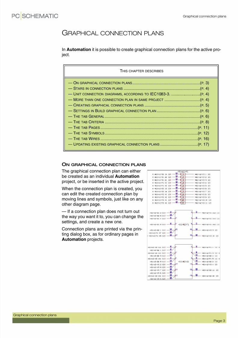
In Automation it is possible to create graphical connection plans for the active pro- ject.
ON GRAPHICAL CONNECTION PLANS
The graphical connection plan can either
be created as an individual Automation project, or be inserted in the active project.
When the connection plan is created, youcan edit the created connection plan bymoving lines and symbols, just like on anyother diagram page.
— If a connection plan does not turn outthe way you want it to, you can change thesettings, and create a new one.
Connection plans are printed via the prin-ting dialog box, as for ordinary pages inAutomation projects.
THIS CHAPTER DESCRIBES
— ON GRAPHICAL CONNECTION PLANS ............................................................. (P. 3)
— STARS IN CONNECTION PLANS ..................................................................... (P. 4)
— UNIT CONNECTION DIAGRAMS, ACCORDING TO IEC1083-3. ..........................(P. 4)
— MORE THAN ONE CONNECTION PLAN IN SAME PROJECT ................................(P. 4)
— CREATING GRAPHICAL CONNECTION PLANS ..................................................(P. 5)
— SETTINGS IN BUILD GRAPHICAL CONNECTION PLAN .......................................(P. 6)
— THE
TAB
GENERAL
...................................................................................... (P. 6)— THE TAB CRITERIA ...................................................................................... (P. 8)
— THE TAB PAGES ........................................................................................ (P. 11)
— THE TAB SYMBOLS .................................................................................... (P. 12)
— THE TAB WIRES ........................................................................................ (P. 16)
— UPDATING EXISTING GRAPHICAL CONNECTION PLANS ..................................(P. 17)

7/28/2019 UK ConnectionPlans v12 74-100 066-001
http://slidepdf.com/reader/full/uk-connectionplans-v12-74-100-066-001 4/18
Graphical connection plans
Page 4
Graphical connection plans
STARS IN CONNECTION PLANS
When you mount based onthe connection plan, and thereis a star (*) next to a wire, thismeans that this wire should
already be mounted, whenyou get to this point.
This is only the case if youmount the components follo-wing the exact order, in whichthey appear in the connectionplan — starting with the firstpage of the connection plan.
UNIT CONNECTION DIAGRAMS, ACCORDING TO IEC1083-3
The graphical connection plans which you can create here, are called unit connec- tion diagrams using interrupted lines in the IEC1083-3 standard.
MORE THAN ONE CONNECTION PLAN IN THE SAME PROJECT
It is possible to create more than one graphical connection plans in the same pro- ject. When you wish to update a graphical connection plan, you must select one ofthe pages containing the connection plan in the project, and choose Tools => Gra-phical connection plan.
Must be mounted, when you get to this point

7/28/2019 UK ConnectionPlans v12 74-100 066-001
http://slidepdf.com/reader/full/uk-connectionplans-v12-74-100-066-001 5/18
Graphical connection plans
Graphical connection plans
Page 5
CREATING GRAPHICAL CONNECTION PLANS
To create a graphical connection plan, choose Tools => Graphical connectionplan in Automation. You then enter the dialog box Create new graphical con-nection plan, which is described in the following.
Updating a graphical connection plan
If you have selected a page in a project, which contains an existing graphical con-nection plan, you enter the dialog box Update graphical connection plan, whichis described in “Rebuilding existing connection plans” on page 17.
Inserting the connection plan in the project
If you have not chosen a connection plan page in the project, a new graphical con-nection plan is created. When the connection plan is created, you are askedwhether to insert it in the project:
Answer Yes - to insert the connection plan in the project
If you answer Yes to insert the connection plan in the project, together with a tab
page named Connectionplan.
Answer No - to insert the connection plan in the project
If you answer No in the dialog box, the connection plan is created as an indepen-dent Automation project with the name Connectionplan.
Page type for connection plans
The pages in the connection plan are assigned the page type CNP . In Automation they therefore have no influence on the electrical and mechanical lists in the pro- ject.
NOT UPDATED AUTOMATICALLY
IF YOU MAKE CHANGES IN THE DIAGRAM PAGES IN THE ORIGINAL Automa-tion PROJECT, THE CONNECTION PLAN IS NOT UPDATED AUTOMATICALLY.TO UPDATE THE CONNECTION PLAN, YOU MUST THEREFORE CHOOSE TOOLS => GRAPHICAL CONNECTION PLAN AGAIN — AS DESCRIBED IN “REBUIL-DING EXISTING CONNECTION PLANS” ON PAGE 17.

7/28/2019 UK ConnectionPlans v12 74-100 066-001
http://slidepdf.com/reader/full/uk-connectionplans-v12-74-100-066-001 6/18
Graphical connection plans
Page 6
Graphical connection plans
SETTINGS IN BUILD GRAPHICAL CONNECTION PLAN
The dialog box Build graphical connection plan contains the following tabs:
The functions on the tabs are described in the following.
Create the graphical connection plan
When you have made the desired choices on the tabs, click on OK in the right-hand side of the dialog box. Then the graphical connec-tion plan for the chosen components is created/updated.
If you click Cancel, you exit the dialog box, and no connection planis created.
If you click Reset, the settings in the dialog box are reset to the
default settings for the program.
GENERAL
On the tab General you specify the orientation of the graphical connection plan:
TAB FUNCTION PAGE
G ENERAL HERE YOU SPECIFY THE ORIENTATION OF THE GRAPHICAL CON-NECTION PLAN.
(P. 6)
C RITERIA HERE YOU SPECIFY CRITERIA FOR WHICH COMPONENTS YOU WISH TO INCLUDE IN THE CONNECTION PLAN.
(P. 8)
P AGES HERE YOU CHOOSE A DRAWING HEADER FOR THE CONNECTION PLAN.
(P. 11)
S YMBOLS HERE YOU CHOOSE WHICH TERMINAL SYMBOL TO APPLY, AND WHETHER TO USE BLACKBOX SYMBOLS.
(P. 12)
W IRES HERE YOU CHOOSE WHICH TEXTS TO PLACE NEXT TO THE WIRES IN THE DOCUMENTATION.
(P. 16)

7/28/2019 UK ConnectionPlans v12 74-100 066-001
http://slidepdf.com/reader/full/uk-connectionplans-v12-74-100-066-001 7/18
Graphical connection plans
Graphical connection plans
Page 7
You have the following three options:
Columns vertically
Click here to create a connection plan, where the components are
placed in as many vertical columns as possible on each page.
One column vertically
Click here to create a connection plan with one vertical column ofcomponents on each page.
Rows horizontally
Click here to create a connection plan, where the components areplaced in as many horizontal rows as possible on each page.
7/28/2019 UK ConnectionPlans v12 74-100 066-001
http://slidepdf.com/reader/full/uk-connectionplans-v12-74-100-066-001 8/18
Graphical connection plans
Page 8
Graphical connection plans
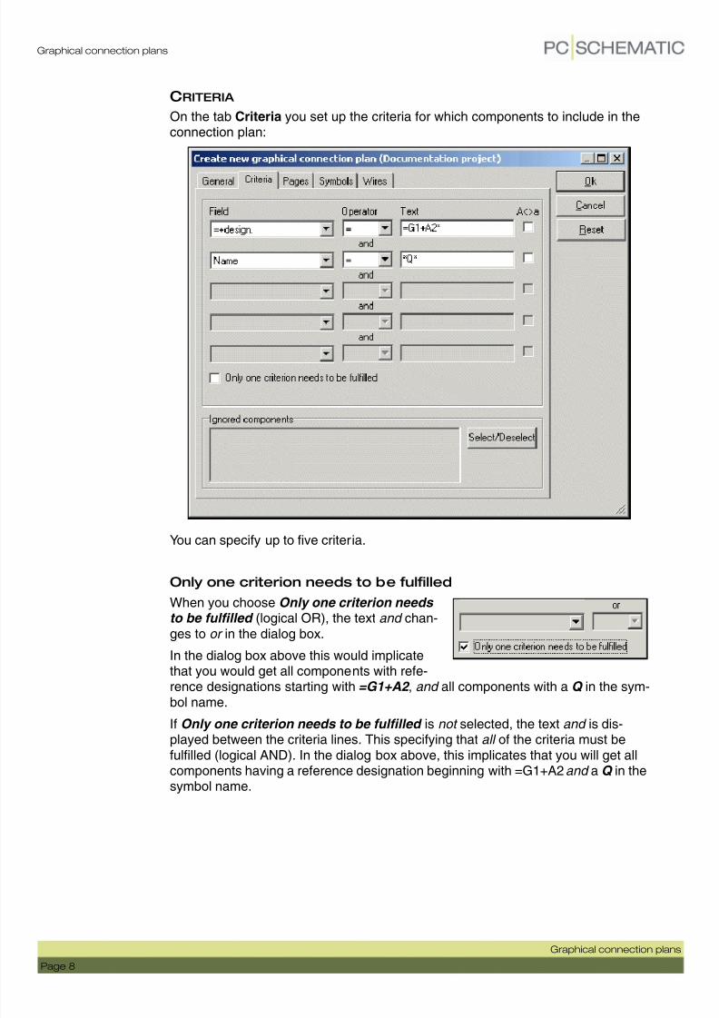
CRITERIA
On the tab Criteria you set up the criteria for which components to include in theconnection plan:
You can specify up to five criteria.
Only one criterion needs to be fulfilled
When you choose Only one criterion needs to be fulfilled (logical OR), the text and chan-ges to or in the dialog box.
In the dialog box above this would implicatethat you would get all components with refe-rence designations starting with =G1+A2 , and all components with a Q in the sym-bol name.
If Only one criterion needs to be fulfilled is not selected, the text and is dis-played between the criteria lines. This specifying that all of the criteria must befulfilled (logical AND). In the dialog box above, this implicates that you will get allcomponents having a reference designation beginning with =G1+A2 and a Q in thesymbol name.

7/28/2019 UK ConnectionPlans v12 74-100 066-001
http://slidepdf.com/reader/full/uk-connectionplans-v12-74-100-066-001 9/18
Graphical connection plans
Graphical connection plans
Page 9
Specifying a criterion
When clicking under Field , you specify which datafield the criterion is set for. Thisbeing one of the symbol texts Name , Type , Article No. or Function , or a referencedesignation (=+design.).
If you set Operator to =, you can type in which text, that the contents of the data-
field must be identical to, under Text .
If the contents of the datafield must be different from what you type in under Text ,set the Operator to <>.
To specify whether the contents of the datafield must be larger than or smaller thanthe specified text, set the operator to > or < respectively. Please note that youhereby specify whether the text comes before or after the criterion alphabetically.
When you select A<>a, you specify that there shall be made a distinction betweenupper case and lower case letters.
W ILDCARDS
When for instance you wish to document all components having the letter Q in the name, you need a way of specifying this to the program.
For this purpose, you can use the so-called wildcards, which are also used inWindows. These characters are ? and *.
When you place a ? somewhere in the text, this means that there must beone (and only one) character on this position.
When you place a *, this indicates that there can be an arbitrary number of
characters on this position.
If for instance you wish to extract all components with exactly three letters,with the letter Q as the second character, you write ?Q?. This specifies thatthere shall be one — and only one — character before Q, and one — andonly one — character after.
If you wish to extract all components with an A anywhere in the text, write*A*.
— Please note that when you write ? there must be a character on this posi-
tion, but when you write * this also covers the case where there are no cha-racters.
7/28/2019 UK ConnectionPlans v12 74-100 066-001
http://slidepdf.com/reader/full/uk-connectionplans-v12-74-100-066-001 10/18
Graphical connection plans
Page 10
Graphical connection plans
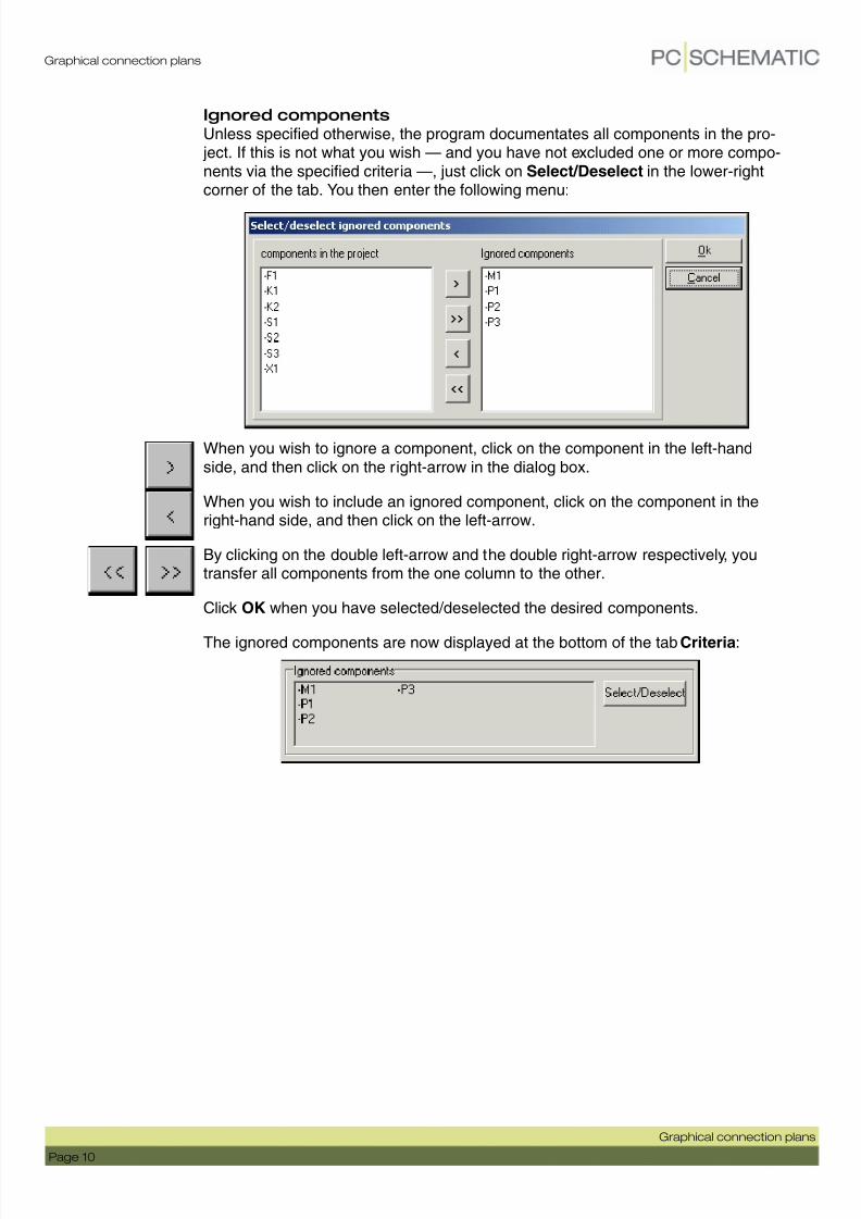
Ignored components
Unless specified otherwise, the program documentates all components in the pro- ject. If this is not what you wish — and you have not excluded one or more compo-nents via the specified criteria —, just click on Select/Deselect in the lower-rightcorner of the tab. You then enter the following menu:
When you wish to ignore a component, click on the component in the left-handside, and then click on the right-arrow in the dialog box.
When you wish to include an ignored component, click on the component in theright-hand side, and then click on the left-arrow.
By clicking on the double left-arrow and the double right-arrow respectively, youtransfer all components from the one column to the other.
Click OK when you have selected/deselected the desired components.
The ignored components are now displayed at the bottom of the tab Criteria:

7/28/2019 UK ConnectionPlans v12 74-100 066-001
http://slidepdf.com/reader/full/uk-connectionplans-v12-74-100-066-001 11/18
Graphical connection plans
Graphical connection plans
Page 11
P AGES
On the tab Pages you select which drawing header to use in the graphical connec-tion plan.
Drawing header
In the field Drawing header you specify which drawing header to use in thecreated connection plan.
When you click the down-arrow in the Drawing header field, you get the list of dra-wing headers in Automation, and can choose which drawing header to use. Youcan only use drawing headers, which are in this list.
User-defined drawing headers
If you have designed your own drawing header for connection plans, you must firstadd it to the list of drawing headers in Automation.
When you have done this, you will be able to choose the drawing header on the tabPages.
— Read more about this, and about designing drawing headers, in the Automa-tion manual.

7/28/2019 UK ConnectionPlans v12 74-100 066-001
http://slidepdf.com/reader/full/uk-connectionplans-v12-74-100-066-001 12/18
Graphical connection plans
Page 12
Graphical connection plans
S YMBOLS
Here you specify which terminal symbol to use in the graphical connection plan,and how to represent the individual components:
Terminal symbol
In the upper part of the dialog box you choose which terminal symbol to use on the
connection plan. When you click the down-arrow, you can choose between the pre-viously used symbols.
The terminal symbols, which you can choose from by default, looks like this:
These symbols are only examples on what you can use for representing terminalsin the connection plan.
If you wish to use another terminal symbol, you can just type in the name of thesymbol in the Terminal symbol text field.
Used for jumpering links

7/28/2019 UK ConnectionPlans v12 74-100 066-001
http://slidepdf.com/reader/full/uk-connectionplans-v12-74-100-066-001 13/18
Graphical connection plans
Graphical connection plans
Page 13
Terminal symbol for displaying Jumpering links in the connection plan
To display jumpering links inthe connection plan, theapplied symbol must haveextra connection points.
These must have IO status Main type and Extension set to none — as displayedin the figure to the right.
Read more about designingsymbols in the Automation manual.
The symbol P_TERM.SYM can be applied for displaying jumpering links in theconnection plan.
Jumpering links are displayed in connection plans as straight lines between the
connection points in the terminal symbols.
Path to the terminal symbol
The file name for the terminal symbol can be typed in with or without a path speci-
fying which folder the symbol is placed in.
When you type in the full path along with the symbol name, the program will alwaysbe able to locate the symbol.
As you can see above, only the symbol name is written in the Terminal symbol field. This is because the symbols are placed in a folder, which has an alias in theAlias for libraries dialog box.
You can enter this dialog box by choosing Settings => Directories, and then clickon Show directory alias.
— Read more about alias in the Automation manual.

7/28/2019 UK ConnectionPlans v12 74-100 066-001
http://slidepdf.com/reader/full/uk-connectionplans-v12-74-100-066-001 14/18
Graphical connection plans
Page 14
Graphical connection plans
Blackbox symbols
When you create a graphical connection plan, the program automatically genera-tes blackbox symbols, which represents the components in the connection plans.
These symbols are boxes with connection points on the sides.
Which connection points, that are placed where on the symbols, can be determi-ned in two ways:
Let the program place the connection points
If you do not select Blackbox symbols from database , the connection points onthe symbols in the connection plan, are placed the following way:
The principle is that connection points with odd numbered connection names areplaced on the left-hand side of the blackbox symbol, and connection points witheven numbered connection names on the right-hand side of the blackbox symbol.
Fetch connection point positions from mechanical symbols
If you choose to use the blackbox symbols, which the program creates (this mea-ning you have not selected Blackbox symbols from database ), and select Con- nection point position from mechanical symbol , the program fetches thepositions of the connection points from the mechanical symbols from the compo-nents database. Then the connection points are placed on the blackbox symbols,as they are placed on the mechanical symbols.
Blackbox symbols from database
If you select Blackbox symbol from database , you can specify from which field in
the database, that the program shall fetch the symbols for the connection plan.
7/28/2019 UK ConnectionPlans v12 74-100 066-001
http://slidepdf.com/reader/full/uk-connectionplans-v12-74-100-066-001 15/18
Graphical connection plans
Graphical connection plans
Page 15
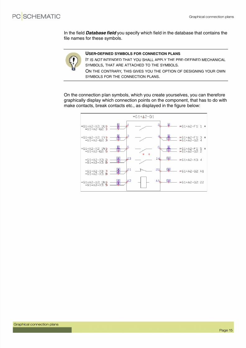
In the field Database field you specify which field in the database that contains thefile names for these symbols.
On the connection plan symbols, which you create yourselves, you can thereforegraphically display which connection points on the component, that has to do withmake contacts, break contacts etc., as displayed in the figure below:
USER-DEFINED SYMBOLS FOR CONNECTION PLANS
IT IS NOT INTENDED THAT YOU SHALL APPLY THE PRE-DEFINED MECHANICAL SYMBOLS, THAT ARE ATTACHED TO THE SYMBOLS.
ON THE CONTRARY, THIS GIVES YOU THE OPTION OF DESIGNING YOUR OWN SYMBOLS FOR THE CONNECTION PLANS.
7/28/2019 UK ConnectionPlans v12 74-100 066-001
http://slidepdf.com/reader/full/uk-connectionplans-v12-74-100-066-001 16/18
Graphical connection plans
Page 16
Graphical connection plans
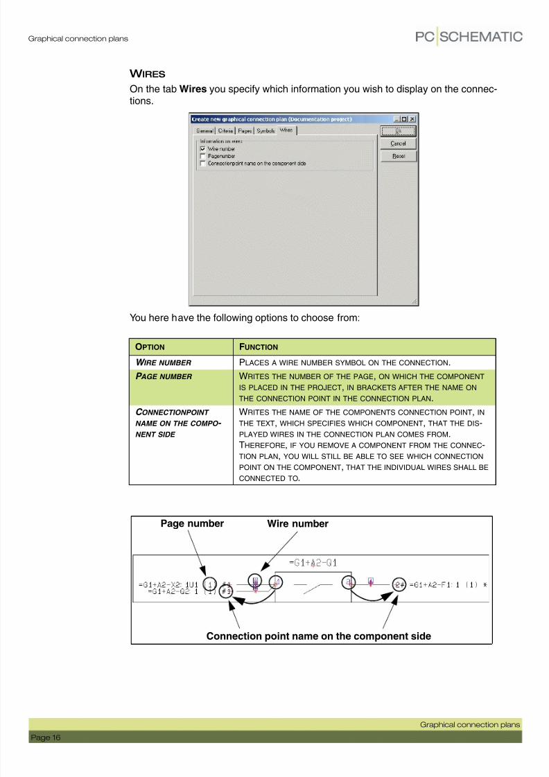
W IRES
On the tab Wires you specify which information you wish to display on the connec-tions.
You here have the following options to choose from:
OPTION FUNCTION
W IRE NUMBER PLACES A WIRE NUMBER SYMBOL ON THE CONNECTION.
P AGE NUMBER WRITES THE NUMBER OF THE PAGE, ON WHICH THE COMPONENT IS PLACED IN THE PROJECT, IN BRACKETS AFTER THE NAME ON THE CONNECTION POINT IN THE CONNECTION PLAN.
C ONNECTIONPOINT NAME ON THE COMPO - NENT SIDE
WRITES THE NAME OF THE COMPONENTS CONNECTION POINT, IN THE TEXT, WHICH SPECIFIES WHICH COMPONENT, THAT THE DIS-PLAYED WIRES IN THE CONNECTION PLAN COMES FROM.THEREFORE, IF YOU REMOVE A COMPONENT FROM THE CONNEC-TION PLAN, YOU WILL STILL BE ABLE TO SEE WHICH CONNECTION POINT ON THE COMPONENT, THAT THE INDIVIDUAL WIRES SHALL BE
CONNECTED TO.
Page number Wire number
Connection point name on the component side
7/28/2019 UK ConnectionPlans v12 74-100 066-001
http://slidepdf.com/reader/full/uk-connectionplans-v12-74-100-066-001 17/18
Graphical connection plans
Graphical connection plans
Page 17
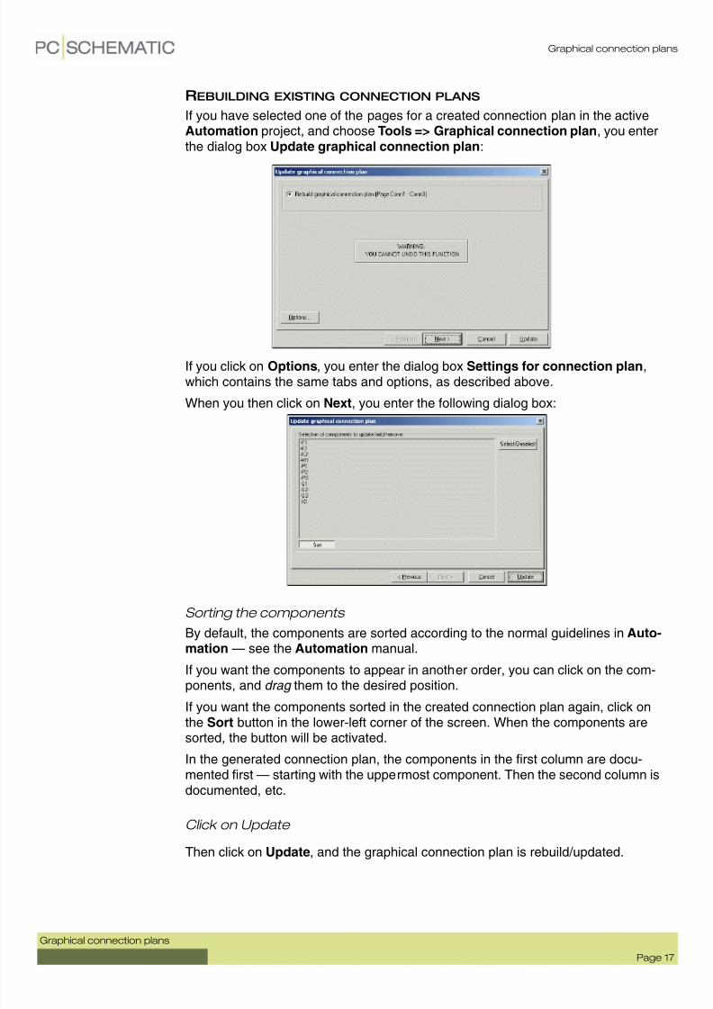
REBUILDING EXISTING CONNECTION PLANS
If you have selected one of the pages for a created connection plan in the activeAutomation project, and choose Tools => Graphical connection plan, you enterthe dialog box Update graphical connection plan:
If you click on Options, you enter the dialog box Settings for connection plan,which contains the same tabs and options, as described above.
When you then click on Next, you enter the following dialog box:
Sorting the components
By default, the components are sorted according to the normal guidelines in Auto-mation — see the Automation manual.
If you want the components to appear in another order, you can click on the com-ponents, and drag them to the desired position.
If you want the components sorted in the created connection plan again, click onthe Sort button in the lower-left corner of the screen. When the components aresorted, the button will be activated.
In the generated connection plan, the components in the first column are docu-mented first — starting with the uppermost component. Then the second column isdocumented, etc.
Click on Update
Then click on Update, and the graphical connection plan is rebuild/updated.

7/28/2019 UK ConnectionPlans v12 74-100 066-001
http://slidepdf.com/reader/full/uk-connectionplans-v12-74-100-066-001 18/18
Graphical connection plans
Graphical Terminal- and Cable plans
GRAPHICAL TERMINAL- AND C ABLE PLANS
This chapter describes changes in the graphical terminal plans and cable plans inAutomation.
MORE THAN ONE GRAPHICAL PLAN IN THE SAME PROJECT
It is now both possible to have more than one graphical terminal plan, and morethan one graphical cable plan in the same project.
To update one of these cable-/terminal plans, you must select one of the pages inthe relevant cable-/terminal plan, when you choose Tools => Graphical cable-/ terminal plan.
By setting up criteria — see “Settings for Criteria for all types of graphical plans” onpage 18 — you can hereby create graphical cable-/terminal plans, which repre-sents different parts of the project.
Creating a new graphical cable-/terminal plan
When you wish to create a new graphical cable-/terminal plan, you must firstchoose a page in the active project, which is not a graphical cable-/terminal plan,when you choose Tools => Graphical cable-/terminal plan.
SETTINGS FOR CRITERIA FOR ALL TYPES OF GRAPHICAL PLANS
You can also set up criteria for which terminal rows to include in graphical terminalplans, and to set up criteria for which cables to include in graphical cable plans.
This is done via the tab Criteria, as described in “Criteria” on page 8.
Furthermore, Select/Deselect is moved to the tab Criteria.
SCREENS ON CABLES DISPLAYED
Screens on cables are displayed in graphical terminal-/cable plans.
THIS CHAPTER DESCRIBES
— MORE THAN ONE GRAPHICAL PLAN IN THE SAME PROJECT...........................(P. 18)
— SETTINGS FOR CRITERIA FOR ALL TYPES OF GRAPHICAL PLANS...................(P. 18)
— SCREEN ON CABLES DISPLAYED .................................................................(P. 18)