UHBR OPEN-TEST-CASE FAN ECL5/CATANA PART 1: GEOMETRY …
15
HAL Id: hal-03257374 https://hal.archives-ouvertes.fr/hal-03257374v2 Submitted on 2 Feb 2022 HAL is a multi-disciplinary open access archive for the deposit and dissemination of sci- entific research documents, whether they are pub- lished or not. The documents may come from teaching and research institutions in France or abroad, or from public or private research centers. L’archive ouverte pluridisciplinaire HAL, est destinée au dépôt et à la diffusion de documents scientifiques de niveau recherche, publiés ou non, émanant des établissements d’enseignement et de recherche français ou étrangers, des laboratoires publics ou privés. Copyright UHBR OPEN-TEST-CASE FAN ECL5/CATANA PART 1: GEOMETRY AND AERODYNAMIC PERFORMANCE Christoph Brandstetter, Valdo Pagès, Pierre Duquesne, Xavier Ottavy, Pascal Ferrand, Stéphane Aubert, Laurent Blanc To cite this version: Christoph Brandstetter, Valdo Pagès, Pierre Duquesne, Xavier Ottavy, Pascal Ferrand, et al.. UHBR OPEN-TEST-CASE FAN ECL5/CATANA PART 1: GEOMETRY AND AERODYNAMIC PER- FORMANCE. 14th European Conference on Turbomachinery Fluid dynamics & Thermodynamics, Apr 2021, Gdansk, Poland. hal-03257374v2
Transcript of UHBR OPEN-TEST-CASE FAN ECL5/CATANA PART 1: GEOMETRY …
HAL Id: hal-03257374https://hal.archives-ouvertes.fr/hal-03257374v2
Submitted on 2 Feb 2022
HAL is a multi-disciplinary open accessarchive for the deposit and dissemination of sci-entific research documents, whether they are pub-lished or not. The documents may come fromteaching and research institutions in France orabroad, or from public or private research centers.
L’archive ouverte pluridisciplinaire HAL, estdestinée au dépôt et à la diffusion de documentsscientifiques de niveau recherche, publiés ou non,émanant des établissements d’enseignement et derecherche français ou étrangers, des laboratoirespublics ou privés.
Copyright
UHBR OPEN-TEST-CASE FAN ECL5/CATANAPART 1: GEOMETRY AND AERODYNAMIC
PERFORMANCEChristoph Brandstetter, Valdo Pagès, Pierre Duquesne, Xavier Ottavy, Pascal
Ferrand, Stéphane Aubert, Laurent Blanc
To cite this version:Christoph Brandstetter, Valdo Pagès, Pierre Duquesne, Xavier Ottavy, Pascal Ferrand, et al.. UHBROPEN-TEST-CASE FAN ECL5/CATANA PART 1: GEOMETRY AND AERODYNAMIC PER-FORMANCE. 14th European Conference on Turbomachinery Fluid dynamics & Thermodynamics,Apr 2021, Gdansk, Poland. �hal-03257374v2�
Paper ID: ETC2021-626 Proceedings of 14th European Conference on Turbomachinery Fluid dynamics & Thermodynamics ETC14, April 12-16 2021; Gdansk, Poland
OPEN ACCESS Downloaded from www.euroturbo.eu
1 Copyright © by the Authors
UHBR OPEN-TEST-CASE FAN ECL5/CATANA PART 1: GEOMETRY AND AERODYNAMIC PERFORMANCE
Christoph Brandstetter1*, Valdo Pagès1, Pierre Duquesne1, Xavier Ottavy1, Pascal Ferrand1, Stéphane Aubert1, Laurent Blanc2
1Université de Lyon, École Centrale de Lyon, CNRS, LMFA, UMR 5509, F-69134, ECULLY, France
2Université de Lyon, École Centrale de Lyon, CNRS, LMFA, UMR 5513, F-69134, ECULLY, France
ABSTRACT Application of composite rotors enables disruptive design possibilities but demands for a
fundamental understanding of the dynamic behaviour to ensure robust design and safe operation. Sensitivity to multi-physical resonance between aerodynamic, structure-dynamic and acoustic phenomena is amplified in modern low speed fan designs for UHBR application. Very thin blades, which are required to maintain high efficiency at transonic flow conditions, are flexible and prone to vibrations. As a result, aeroelastic and aeroacoustic problems increasingly set the stability limit.
Test cases of representative geometries without industrial restrictions are a key element of an open scientific culture but currently non-existent in the turbomachinery community. The most commonly used test cases in computational fluid dynamics (e.g. NASA Rotor37/67; TUD Rotor 1 etc.) were designed over two decades ago, and their aeroelastic characteristics are not representative of modern turbomachinery. Also, available experiments have not been conducted with a focus on coupling-phenomena and hence did not comprise multi-physical instrumentation.
In order to provide a multi-physical validation benchmark representative of near-future UHBR fan concepts, the open-test-case fan stage ECL5 has been developed at Ecole Centrale de Lyon. Design intention was to develop a geometry with high efficiency and a wide stability range that can be realized using layered carbon fibre composites. The final design iteration of the fan stage is currently fabricated and will be experimentally tested within the European CleanSky-2 project CATANA (Composite Aeroelastics and Aeroacoustics, catana.ec-lyon.fr).
In Part-1 of this publication, the test case is introduced with details on geometry, methodology and aerodynamic design of the whole stage, whereas Part-2 focuses on structure dynamics and aeromechanical stability. An analysis of the calculated aerodynamic performance with a focus on critical flow structures like tip-leakage flow, radial flow migration and flow separations is presented. Furthermore, details on the experimental campaign comprising multi-physical instrumentation anticipated for 2021 are given to highlight the research focus.
KEYWORDS
FAN, COMPOSITE, AEROELASTIC, AEROACOUSTIC, FLUTTER NOMENCLATURE
M Relative Mach Number NSV Non Synchronous Vibration UHBR Ultra High Bypass Ratio Vx Axial Velocity Pt/Tt Total Pressure / Total Temperature OGV Outlet Guide Vanes (Stator)
2
INTRODUCTION
With application of modern lightweight blade geometries aeroelastic coupling phenomena tend to reduce the operating range of compressors and fans in aircraft propulsion engines. As synchronous excitation mechanisms are well understood today, the most challenging aeroelastic phenomena for future turbomachinery applications are of non-synchronous1 nature. A list of these phenomena is presented hereafter: Flutter is defined as self-excited blade vibration and usually involves blade-to-blade coupling. It is considered as initially small amplitude blade oscillation in a specific eigenmode that exponentially amplifies through a positive feedback loop with the aerodynamic field (negative aerodynamic damping). Linear modelling approaches are capable to predict the onset of this mechanism and to determine critical modes and to develop countermeasures. The disturbance is only dependent on the blade vibration and disappears as soon as the vibration stops. For large vibration amplitudes limit-cycle-oscillation may occur due to aerodynamic or structure dynamic non-linearity. For turbo-engine fans critical modes are typically dependent on swirling acoustic modes that establish between the inlet and the fan stage (Vahdati and Cumpsty, 2016). Buffeting describes the interaction between an aerodynamic instability (typically vortex shedding) that comprises a characteristic frequency and blade vibration in a specific eigenmode. Typically, no circumferential blade-to-blade coupling is necessary but often planar acoustic duct modes (Lee, 2001) establish and synchronize the phase of the aerodynamic instabilities leading to a zero-nodal-diameter vibration. Rotating Stall is a purely aerodynamic phenomenon occurring due to overloading of a blade row and subsequent flow separation leading to the establishment of circumferentially propagating stall-cells. It typically excites structural eigenmodes due to unsteady loading but for small amplitudes the propagation is not coupled with the blade vibration (Dodds and Vahdati, 2015). Non-synchronous forced response: In multistage compressors, a non-synchronous coupling mechanism between a trapped acoustic mode, coincident with a structural vibration pattern has been observed. The phenomenon is less relevant for fan applications, details are given in (Fiquet et al., 2019). Convective Non-Synchronous-Vibration (NSV): Typically occurring close to the stability limit but before the onset of rotating stall, a complex lock-in mechanism between propagating aerodynamic vorticity disturbances and blade vibration is described under the term NSV (Kielb et al., 2003; Stapelfeldt and Brandstetter, 2020). Blade vibration leads to the change of free vorticity or even the formation of radial vortices in the passage flow which are convected from blade to blade if sufficient blockage is present in the passage. Interaction with trailing blades leads to modal forcing and the shedding of subsequent vorticity. Propagating aerodynamic disturbances can lock-in with structural vibration patterns and lead to a coherent fluid-structural interaction. The phenomenon needs to be differentiated from flutter as the aerodynamic disturbance appears without blade vibration and has a characteristic convective propagation speed (typically described under the term rotating-instability). For all of the described phenomena, the flow structure in the tip region and particularly the influence of the tip leakage flow and the passage shock is of great importance. Significant blockage enables the circumferential transport of disturbances or provokes separation of the boundary layer which may be susceptible to acoustic or structure-dynamic feedback. For high-speed fans rotating stall, buffeting and flutter are the most common instability mechanisms and well understood today. The establishment of UHBR-configurations with low-speed fans however leads to a substantial change of relevant characteristics. 1 not a multiple of the shaft rotation speed / non-engine-order
3
Low-speed fans will predominantly operate on the flat part of the compression characteristic, making them more susceptible for stall-driven instability (Lee et al., 2017).
The flutter frequencies (in the stationary frame) will be lower compared to high-speed designs. Acoustic liners in the intake, which are designed to attenuate higher frequency community noise will not affect the modes relevant for aero-elastic instability.
The intake length will be shorter for low-speed fans, leading to stronger inflow asymmetry and altered acoustic interaction (Peters et al., 2014). This gives rise to stronger broadband excitation and shifted resonance frequencies.
The relative Mach number and shock strength are lower, the relative tip-clearance and solidity2 smaller than for conventional direct-drive fans and more sensitive to geometric asymmetry (Wilson et al., 2006).
A strongly nonlinear fluid-structure-interaction at low-frequencies has been observed for fans with low solidity related to the pressure untwist of the blades. At transonic conditions, slight deviations of the local stagger angle at the blade tip can cause a fundamentally different shock structure between adjacent blades that affects the stability of distinct rotor sections (Lu et al., 2019). This circumstance affects the applicability of promising methods like intentional blade mistuning (Zhai et al., 2011) to suppress the development of circumferentially propagating modes.
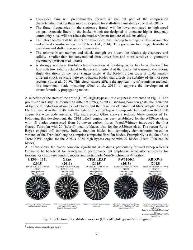
A selection of the state-of the art of (Ultra)-High-Bypass-Ratio engines is presented in Fig. 1. The propulsion industry has focused on different strategies but all showing common goals: the reduction of tip speed, reduction of number of blades and the reduction of individual blade weight. General Electric started in the 1990s with the establishment of layered composite fan blades in the GE90 engine for wide body aircrafts. The more recent GEnx shows a reduced blade number of 18. Following this development, the CFM LEAP engine has been established for the A320neo class, with 18 blades constructed from 3d-woven carbon fibres. Pratt&Whitney introduced the first Geared Turbofan with 20 (hybrid)-metallic blades, also for the A320neo class. The recent Rolls-Royce engines still comprise hollow titanium blades but technology demonstrators based on variants of the Trent1000 engine comprise composite fibre fan blades. Exemplarily is the fan of the Trent XWB engine for the Airbus A350 high bypass engine with 22 blades (Trent 7000 has 20 blades). All of the shown fan blades comprise significant 3D-features, particularly forward sweep which is known to be beneficial for aerodynamic performance but emphasize aeroelastic sensitivity for torsional or chordwise bending modes and particularly Non-Synchronous-Vibration.
GE90 – 115b (2003)
GEnx (2011)
CFM LEAP (2015)
PW1100G (2015)
RR XWB (2013)
22 Carbon blades / Ø 330cm 18 Carbon blades/ Ø 282cm 18 Carbon blades/ Ø 198 cm 20 metallic blades / Ø 206cm 22 Hollow titanium / Ø 300cm BPR 9 BPR 9.1 ~ 9.6 BPR 11 BPR 12 BPR 9.6
2355 rpm (nom) 2560 rpm (nom) 3894 rpm (max) 3500 rpm (max) 2700 rpm (nom) Mtip 1.2 (nom) Mtip 1.11 (nom) Mtip 1.19 (max) Mtip 1.11 (max) Mtip 1.25 (nom)
https://www.geaviation.com/commercial/engines/ge90-engine
https://www.geaviation.com/commercial/engines/genx-engine
https://c-fan.com/products/
https://www.cfmaeroengines.com/engines/leap/
https://www.airbus.com/search.image.html?q=pw1100g&lang=en#searc
hresult-image-all-16
https://www.airlineratings.com/news/a350s-trent-xwb-engine-hits-twin-
milestones/ https://www.flightradar24.com/blog/
wp-content/uploads/2015/07/A350XWB
Tour-23.jpg
Fig. 1: Selection of established modern (Ultra)-High-Bypass-Ratio Engines 2 solidity = blade chord length / pitch
4
In order to enable further technological advancements into this direction, extensive research is necessary to identify and characterize the relevant instability mechanisms for the novel type of low-speed fans. Particularly the complex flow structure at part load and part speed is challenging for state-of-the-art numerical approaches and requires experimental benchmark data on representative geometries. Furthermore, the influence of structural mistuning, which is known to be influential on instability mechanisms as well as the interaction with different types of intake geometries must be investigated. To address these research objectives, an extensive research program in collaboration between Ecole Centrale de Lyon and the Von Karman Institute for Fluid Dynamics has been initiated. A fan module fabricated from composite material has been developed as an open-test-case and will be investigated with a focus on non-synchronous coupling mechanisms between aerodynamics, acoustics and structure dynamics. The fan stage has been designed at Ecole Centrale de Lyon with the intention to be representative of near-future composite low-speed fans in the following terms:
1. General aerodynamic design parameters (Mach number, blade loading, solidity, aspect ratio, hub-to-tip ratio, mass flow density, etc.)
2. Aerodynamic flow structure due to the influence on instability mechanisms (shock patterns, radial flow migration, secondary flow, separations, etc.)
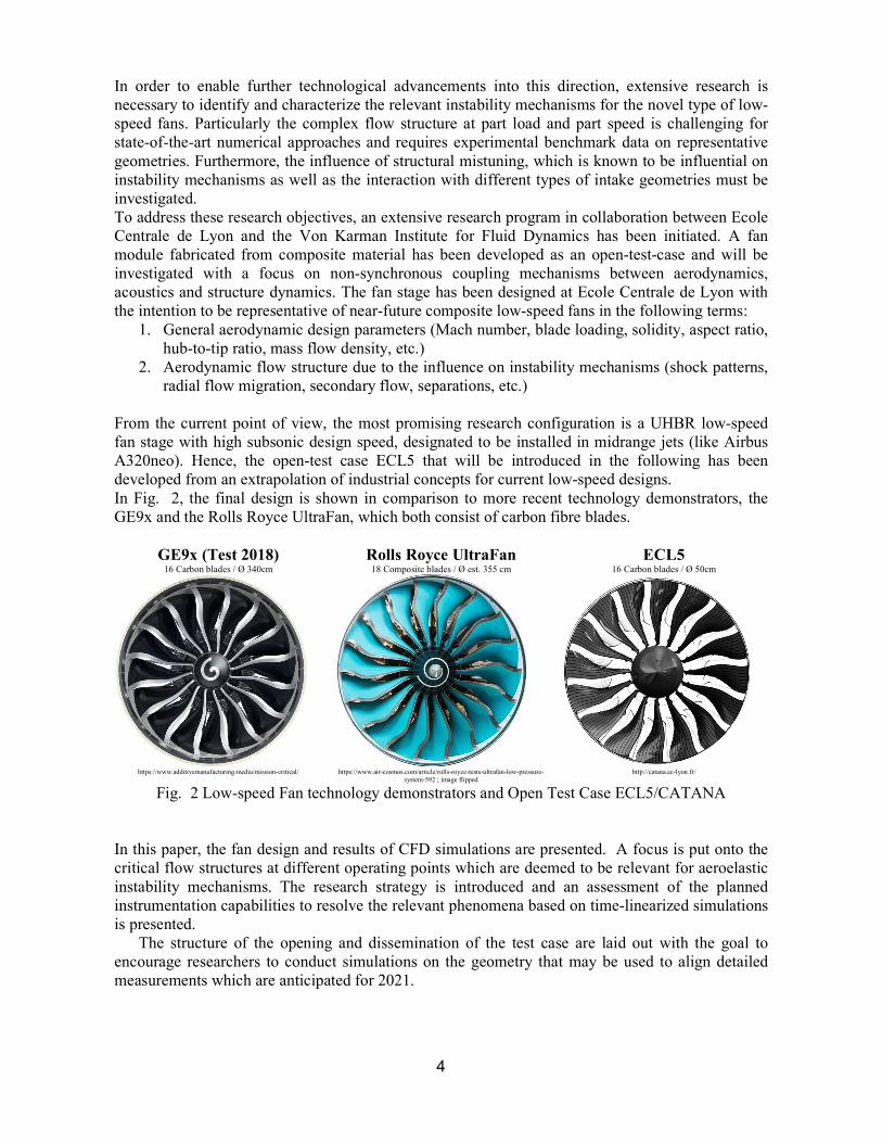
From the current point of view, the most promising research configuration is a UHBR low-speed fan stage with high subsonic design speed, designated to be installed in midrange jets (like Airbus A320neo). Hence, the open-test case ECL5 that will be introduced in the following has been developed from an extrapolation of industrial concepts for current low-speed designs. In Fig. 2, the final design is shown in comparison to more recent technology demonstrators, the GE9x and the Rolls Royce UltraFan, which both consist of carbon fibre blades.
GE9x (Test 2018) Rolls Royce UltraFan ECL5 16 Carbon blades / Ø 340cm 18 Composite blades / Ø est. 355 cm 16 Carbon blades / Ø 50cm
https://www.additivemanufacturing.media/mission-critical/ https://www.air-cosmos.com/article/rolls-royce-tests-ultrafan-low-pressure-
system-592 ; image flipped http://catana.ec-lyon.fr/
Fig. 2 Low-speed Fan technology demonstrators and Open Test Case ECL5/CATANA In this paper, the fan design and results of CFD simulations are presented. A focus is put onto the critical flow structures at different operating points which are deemed to be relevant for aeroelastic instability mechanisms. The research strategy is introduced and an assessment of the planned instrumentation capabilities to resolve the relevant phenomena based on time-linearized simulations is presented.
The structure of the opening and dissemination of the test case are laid out with the goal to encourage researchers to conduct simulations on the geometry that may be used to align detailed measurements which are anticipated for 2021.
5
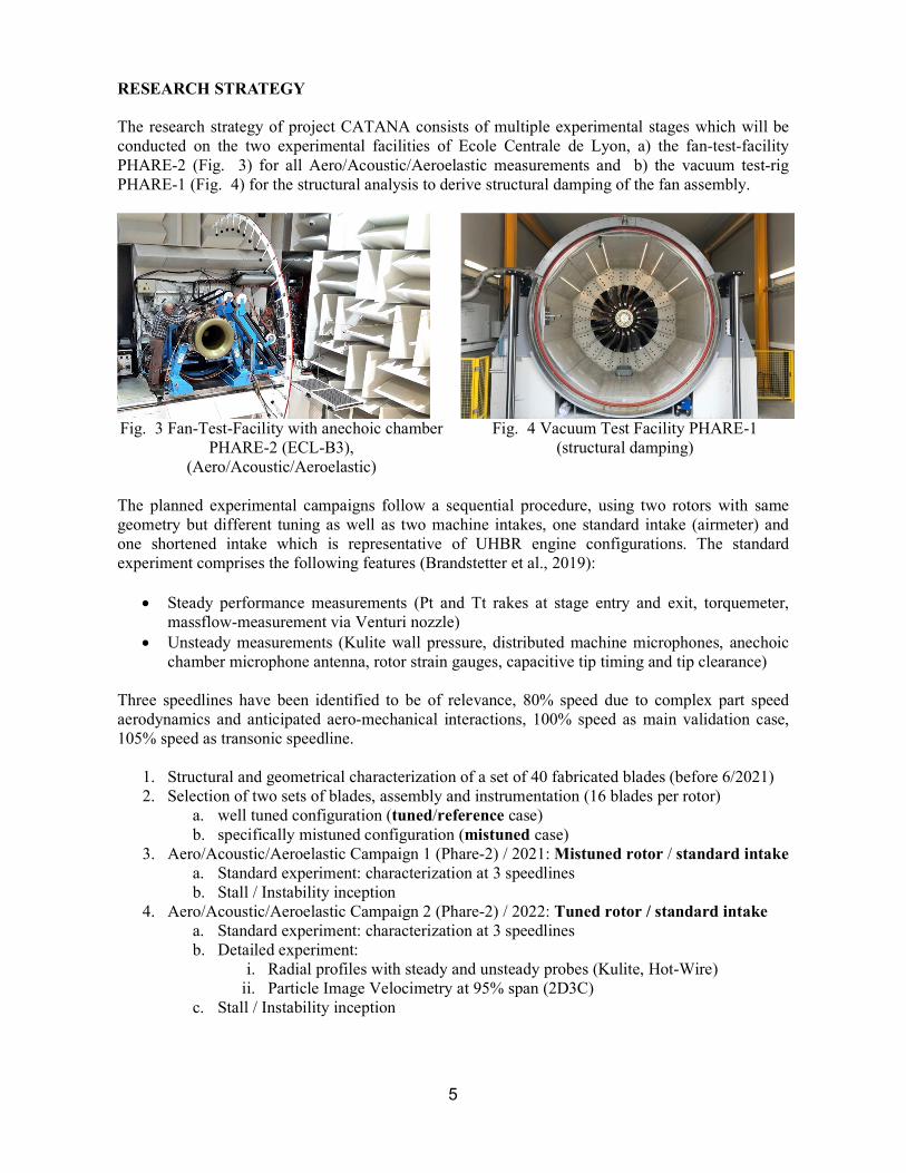
RESEARCH STRATEGY The research strategy of project CATANA consists of multiple experimental stages which will be conducted on the two experimental facilities of Ecole Centrale de Lyon, a) the fan-test-facility PHARE-2 (Fig. 3) for all Aero/Acoustic/Aeroelastic measurements and b) the vacuum test-rig PHARE-1 (Fig. 4) for the structural analysis to derive structural damping of the fan assembly.
Fig. 3 Fan-Test-Facility with anechoic chamber
PHARE-2 (ECL-B3), (Aero/Acoustic/Aeroelastic)
Fig. 4 Vacuum Test Facility PHARE-1
(structural damping)
The planned experimental campaigns follow a sequential procedure, using two rotors with same geometry but different tuning as well as two machine intakes, one standard intake (airmeter) and one shortened intake which is representative of UHBR engine configurations. The standard experiment comprises the following features (Brandstetter et al., 2019):
Steady performance measurements (Pt and Tt rakes at stage entry and exit, torquemeter, massflow-measurement via Venturi nozzle)
Unsteady measurements (Kulite wall pressure, distributed machine microphones, anechoic chamber microphone antenna, rotor strain gauges, capacitive tip timing and tip clearance)
Three speedlines have been identified to be of relevance, 80% speed due to complex part speed aerodynamics and anticipated aero-mechanical interactions, 100% speed as main validation case, 105% speed as transonic speedline.
1. Structural and geometrical characterization of a set of 40 fabricated blades (before 6/2021) 2. Selection of two sets of blades, assembly and instrumentation (16 blades per rotor)
a. well tuned configuration (tuned/reference case) b. specifically mistuned configuration (mistuned case)
3. Aero/Acoustic/Aeroelastic Campaign 1 (Phare-2) / 2021: Mistuned rotor / standard intake a. Standard experiment: characterization at 3 speedlines b. Stall / Instability inception
4. Aero/Acoustic/Aeroelastic Campaign 2 (Phare-2) / 2022: Tuned rotor / standard intake a. Standard experiment: characterization at 3 speedlines b. Detailed experiment:
i. Radial profiles with steady and unsteady probes (Kulite, Hot-Wire) ii. Particle Image Velocimetry at 95% span (2D3C)
c. Stall / Instability inception
6
5. Aero/Acoustic/Aeroelastic Campaign 3 (Phare-2) / 2022: Tuned rotor / short intake a. Standard experiment: characterization at 3 speedlines b. Detailed experiment: Particle Image Velocimetry at 95% span (2D3C) c. Stall / Instability inception
6. Structural Campaign (Phare-1) / 2023 Tuned rotor a. Excitation of the rotor blades with piezo-actuators under rotation in a vacuum-
chamber (Mabilia et al., 2019), measurement of structural damping via strain gauges
THE OPEN TEST CASE ECL5 Test Case Establishment The open test case ECL5 will be established according to the following procedure:
In the first step, that has been finished in summer 2020, the fan design has been finalized and is ready for distribution, starting with the present publication upon registration under catana.ec-lyon.fr
In 2021, the measurement campaigns will start with continuous publications of the gained results
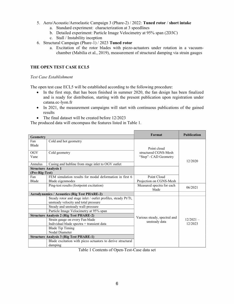
The final dataset will be created before 12/2023 The produced data will encompass the features listed in Table 1.
Format Publication Geometry Fan Blade
Cold and hot geometry
Point cloud structured CGNS-Mesh “Step”- CAD Geometry
12/2020
OGV Vane
Cold geometry
Annulus Casing and hubline from stage inlet to OGV outlet Structure Analysis 1 (Pre-Rig-Test)
Fan Blade
FEM simulation results for modal deformation in first 6 Blade eigenmodes
Point Cloud Projection on CGNS-Mesh
Ping-test results (footpoint excitation) Measured spectra for each blade
06/2021
Aerodynamics / Acoustics (Rig Test PHARE-2) Steady rotor and stage inlet / outlet profiles, steady Pt/Tt,
unsteady velocity and total pressure
Various steady, spectral and unsteady data
12/2021 – 12/2023
Steady and unsteady wall-pressure Particle Image Velocimetry at 95% span Structure Analysis 2 (Rig Test PHARE-2) Strain gauge on every Fan blade
Individual blade spectra + transient data Blade Tip Timing
Nodal Diameter Structure Analysis 3 (Rig Test PHARE-1) Blade excitation with piezo actuators to derive structural
damping
Table 1 Contents of Open-Test-Case data set
7
Design Approach Based on an initial approach described in (Rendu, 2016; Rendu et al., 2020), a modularly coupled design chain, including a parametric blade geometry generator, automatic meshing (Autogrid3), a steady RANS Solver (FineTurbo3), and structural FEM Simulations (Ansys4) has been set up to achieve a fan geometry that fulfils the following design objectives:
Blade Number of 16 (lowest established blade count in technology demonstrators as shown above)
Fan Diameter 508mm to enable integration into test facility PHARE-2, blade root compatible to existing disk from Project ENOVAL (Rodrigues et al., 2020)
(Rotor-only) Aerodynamic Design Point at peak efficiency with a pressure ratio of 1.36, mass flow density maximum of 200 kg/s/m2 and a rotation speed of 11000 rpm
Near sonic relative tip Mach-number at Design Point Rotor-only isentropic efficiency exceeding 94% at design point At peak pressure of design speed no flow separation at the trailing edge Peak efficiency at 105% speed not lower than 92% (transonic speedline) Nominal tip clearance ~1mm (1.1 % chord) to ensure stall inception and surge experiments
without casing contact, future experiments are planned with further reduced tip clearance The rotor will be realized without integration of a metallic leading edge
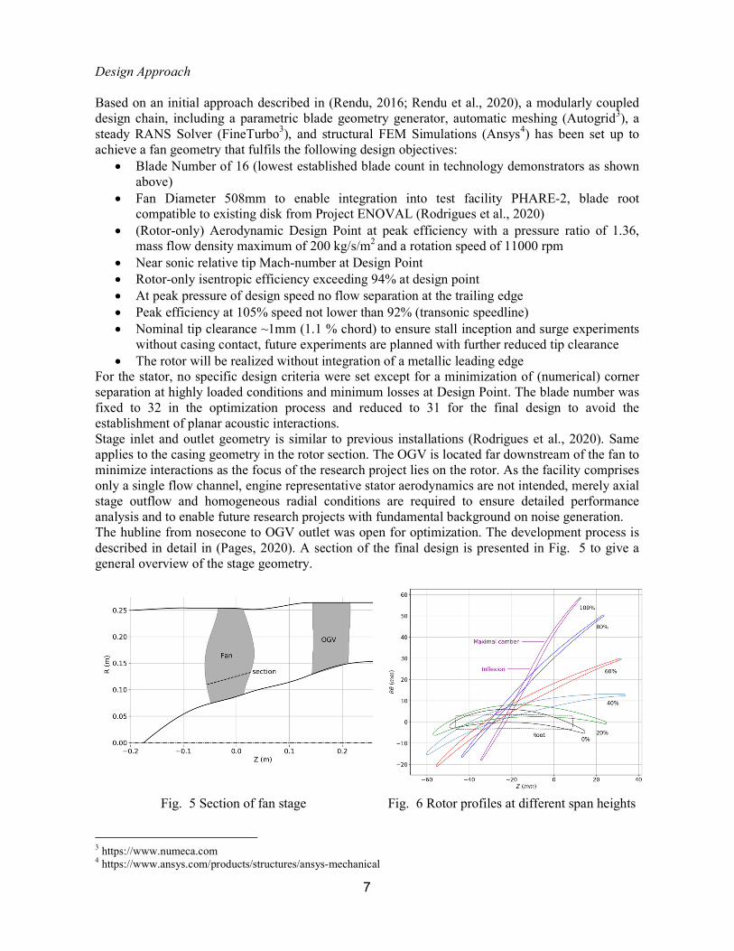
For the stator, no specific design criteria were set except for a minimization of (numerical) corner separation at highly loaded conditions and minimum losses at Design Point. The blade number was fixed to 32 in the optimization process and reduced to 31 for the final design to avoid the establishment of planar acoustic interactions. Stage inlet and outlet geometry is similar to previous installations (Rodrigues et al., 2020). Same applies to the casing geometry in the rotor section. The OGV is located far downstream of the fan to minimize interactions as the focus of the research project lies on the rotor. As the facility comprises only a single flow channel, engine representative stator aerodynamics are not intended, merely axial stage outflow and homogeneous radial conditions are required to ensure detailed performance analysis and to enable future research projects with fundamental background on noise generation. The hubline from nosecone to OGV outlet was open for optimization. The development process is described in detail in (Pages, 2020). A section of the final design is presented in Fig. 5 to give a general overview of the stage geometry.
Fig. 5 Section of fan stage Fig. 6 Rotor profiles at different span heights
3 https://www.numeca.com 4 https://www.ansys.com/products/structures/ansys-mechanical
8
Fig. 6 shows the blade profiles at different span heights, clearly emphasizing the transonic blade design at the rotor tip and the wide chord geometry around midspan. At the hub, the relative exit flow angle is positive with respect to the machine axis, which is necessary to meet the design criteria laid out above but creates a challenging flow field with high swirl velocities at the OGV inlet. The tip clearance in dependence of the rotation speed is presented in Table 2:
Rotation Speed (100% = 11000 rpm)
Tip Clearance [mm] Tip Clearance [% tip chord] Leading Edge Trailing Edge Leading Edge Trailing Edge
0 % 1.00 1.50 1.11 1.67 50 % 0.98 1.30 1.09 1.45 80 % 0.87 1.12 0.97 1.25 100 % 0.78 0.99 0.87 1.10 105 % 0.77 0.92 0.86 1.02
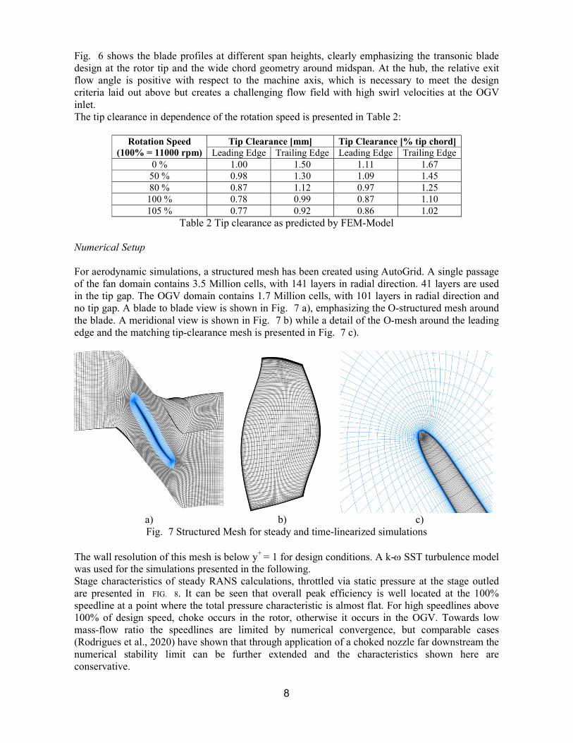
Table 2 Tip clearance as predicted by FEM-Model Numerical Setup For aerodynamic simulations, a structured mesh has been created using AutoGrid. A single passage of the fan domain contains 3.5 Million cells, with 141 layers in radial direction. 41 layers are used in the tip gap. The OGV domain contains 1.7 Million cells, with 101 layers in radial direction and no tip gap. A blade to blade view is shown in Fig. 7 a), emphasizing the O-structured mesh around the blade. A meridional view is shown in Fig. 7 b) while a detail of the O-mesh around the leading edge and the matching tip-clearance mesh is presented in Fig. 7 c).
a) b) c) Fig. 7 Structured Mesh for steady and time-linearized simulations
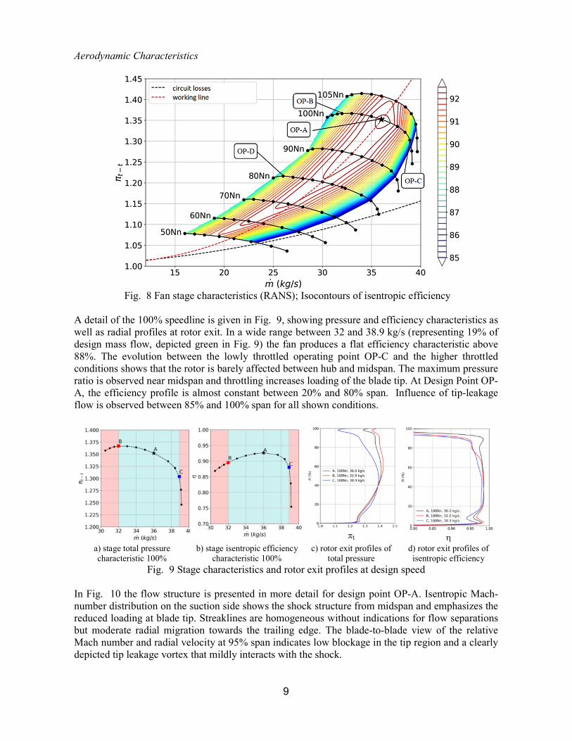
The wall resolution of this mesh is below y+ = 1 for design conditions. A k- SST turbulence model was used for the simulations presented in the following. Stage characteristics of steady RANS calculations, throttled via static pressure at the stage outled are presented in FIG. 8. It can be seen that overall peak efficiency is well located at the 100% speedline at a point where the total pressure characteristic is almost flat. For high speedlines above 100% of design speed, choke occurs in the rotor, otherwise it occurs in the OGV. Towards low mass-flow ratio the speedlines are limited by numerical convergence, but comparable cases (Rodrigues et al., 2020) have shown that through application of a choked nozzle far downstream the numerical stability limit can be further extended and the characteristics shown here are conservative.
9
Aerodynamic Characteristics
Fig. 8 Fan stage characteristics (RANS); Isocontours of isentropic efficiency
A detail of the 100% speedline is given in Fig. 9, showing pressure and efficiency characteristics as well as radial profiles at rotor exit. In a wide range between 32 and 38.9 kg/s (representing 19% of design mass flow, depicted green in Fig. 9) the fan produces a flat efficiency characteristic above 88%. The evolution between the lowly throttled operating point OP-C and the higher throttled conditions shows that the rotor is barely affected between hub and midspan. The maximum pressure ratio is observed near midspan and throttling increases loading of the blade tip. At Design Point OP-A, the efficiency profile is almost constant between 20% and 80% span. Influence of tip-leakage flow is observed between 85% and 100% span for all shown conditions.
t a) stage total pressure characteristic 100%
b) stage isentropic efficiency characteristic 100%
c) rotor exit profiles of total pressure
d) rotor exit profiles of isentropic efficiency
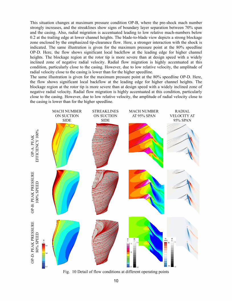
Fig. 9 Stage characteristics and rotor exit profiles at design speed In Fig. 10 the flow structure is presented in more detail for design point OP-A. Isentropic Mach-number distribution on the suction side shows the shock structure from midspan and emphasizes the reduced loading at blade tip. Streaklines are homogeneous without indications for flow separations but moderate radial migration towards the trailing edge. The blade-to-blade view of the relative Mach number and radial velocity at 95% span indicates low blockage in the tip region and a clearly depicted tip leakage vortex that mildly interacts with the shock.
10
This situation changes at maximum pressure condition OP-B, where the pre-shock mach number strongly increases, and the streaklines show signs of boundary layer separation between 70% span and the casing. Also, radial migration is accentuated leading to low relative mach-numbers below 0.2 at the trailing edge at lower channel heights. The blade-to-blade view depicts a strong blockage zone enclosed by the emphasized tip-clearance flow. Here, a stronger interaction with the shock is indicated. The same illustration is given for the maximum pressure point at the 80% speedline OP-D. Here, the flow shows significant local backflow at the leading edge for higher channel heights. The blockage region at the rotor tip is more severe than at design speed with a widely inclined zone of negative radial velocity. Radial flow migration is highly accentuated at this condition, particularly close to the casing. However, due to low relative velocity, the amplitude of radial velocity close to the casing is lower than for the higher speedline. The same illustration is given for the maximum pressure point at the 80% speedline OP-D. Here, the flow shows significant local backflow at the leading edge for higher channel heights. The blockage region at the rotor tip is more severe than at design speed with a widely inclined zone of negative radial velocity. Radial flow migration is highly accentuated at this condition, particularly close to the casing. However, due to low relative velocity, the amplitude of radial velocity close to the casing is lower than for the higher speedline.
MACH NUMBER ON SUCTION
SIDE
STREAKLINES ON SUCTION
SIDE
MACH NUMBER AT 95% SPAN
RADIAL VELOCITY AT
95% SPAN
OP-
A: P
EA
K
EF
FIC
IEN
CY
100
%
SPE
ED
OP-
B: P
EA
K P
RE
SSU
RE
10
0% S
PE
ED
OP-
D: P
EA
K P
RE
SSU
RE
80
% S
PE
ED
Fig. 10 Detail of flow conditions at different operating points
11
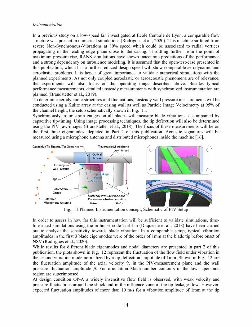
Instrumentation In a previous study on a low-speed fan investigated at Ecole Centrale de Lyon, a comparable flow structure was present in numerical simulations (Rodrigues et al., 2020). This machine suffered from severe Non-Synchronous-Vibrations at 80% speed which could be associated to radial vortices propagating in the leading edge plane close to the casing. Throttling further from the point of maximum pressure rise, RANS simulations have shown inaccurate predictions of the performance and a strong dependency on turbulence modeling. It is assumed that the open-test-case presented in this publication, which has a further reduced design speed will show comparable aerodynamic and aeroelastic problems. It is hence of great importance to validate numerical simulations with the planned experiments. As not only coupled aeroelastic or aeroacoustic phenomena are of relevance, the experiments will also focus on the operating range described above. Besides typical performance measurements, detailed unsteady measurements with synchronized instrumentation are planned (Brandstetter et al., 2019). To determine aerodynamic structures and fluctuations, unsteady wall pressure measurements will be conducted using a Kulite array at the casing wall as well as Particle Image Velocimetry at 95% of the channel height, the setup schematically shown in Fig. 11. Synchronously, rotor strain gauges on all blades will measure blade vibrations, accompanied by capacitive tip-timing. Using image processing techniques, the tip deflection will also be determined using the PIV raw-images (Brandstetter et al., 2018). The focus of these measurements will be on the first three eigenmodes, depicted in Part 2 of this publication. Acoustic signatures will be measured using a microphone antenna and distributed microphones inside the machine [16].
Fig. 11 Planned Instrumentation concept; Schematic of PIV Setup
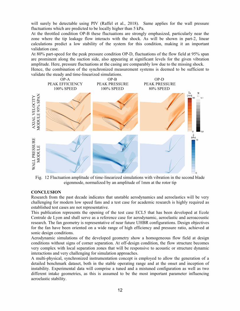
In order to assess in how far this instrumentation will be sufficient to validate simulations, time-linearized simulations using the in-house code TurbLin (Duquesne et al., 2018) have been carried out to analyze the sensitivity towards blade vibration. In a comparable setup, typical vibration amplitudes in the first 3 blade eigenmodes were of the order of 1mm at the blade tip before onset of NSV (Rodrigues et al., 2020). While results for different blade eigenmodes and nodal diameters are presented in part 2 of this publication, the plots shown in Fig. 12 represent the fluctuation of the flow field under vibration in the second vibration mode normalized by a tip deflection amplitude of 1mm. Shown in Fig. 12 are the fluctuation amplitude of the axial velocity 𝑣x in the PIV-measurement plane and the wall pressure fluctuation amplitude �̂�. For orientation Mach-number contours in the low supersonic region are superimposed. At design condition OP-A a widely insensitive flow field is observed, with weak velocity and pressure fluctuations around the shock and in the influence zone of the tip leakage flow. However, expected fluctuation amplitudes of more than 10 m/s for a vibration amplitude of 1mm at the tip
12
will surely be detectable using PIV (Raffel et al., 2018). Same applies for the wall pressure fluctuations which are predicted to be locally higher than 5 kPa. At the throttled condition OP-B these fluctuations are strongly emphasized, particularly near the zone where the tip leakage flow interacts with the shock. As will be shown in part-2, linear calculations predict a low stability of the system for this condition, making it an important validation case. At 80% part-speed for the peak pressure condition OP-D, fluctuations of the flow field at 95% span are prominent along the suction side, also appearing at significant levels for the given vibration amplitude. Here, pressure fluctuations at the casing are comparably low due to the missing shock. Hence, the combination of the synchronized measurement systems is deemed to be sufficient to validate the steady and time-linearized simulations.
OP-A PEAK EFFICIENCY
100% SPEED
OP-B PEAK PRESSURE
100% SPEED
OP-D PEAK PRESSURE
80% SPEED
AX
IAL
VE
LO
CIT
Y
MO
DU
LE
95%
SPA
N
WA
LL
PR
ES
SUR
E
MO
DU
LE
Fig. 12 Fluctuation amplitude of time-linearized simulations with vibration in the second blade
eigenmode, normalized by an amplitude of 1mm at the rotor tip
CONCLUSION Research from the past decade indicates that unstable aerodynamics and aeroelastics will be very challenging for modern low speed fans and a test case for academic research is highly required as established test cases are not representative. This publication represents the opening of the test case ECL5 that has been developed at Ecole Centrale de Lyon and shall serve as a reference case for aerodynamic, aeroelastic and aeroacoustic research. The fan geometry is representative of near future UHBR configurations. Design objectives for the fan have been oriented on a wide range of high efficiency and pressure ratio, achieved at sonic design conditions. Aerodynamic simulations of the developed geometry show a homogeneous flow field at design conditions without signs of corner separation. At off-design condition, the flow structure becomes very complex with local separation zones that will be responsive to acoustic or structure dynamic interactions and very challenging for simulation approaches. A multi-physical, synchronized instrumentation concept is employed to allow the generation of a detailed benchmark dataset, both in the stable operating range and at the onset and inception of instability. Experimental data will comprise a tuned and a mistuned configuration as well as two different intake geometries, as this is assumed to be the most important parameter influencing aeroelastic stability.
13
The test case will be openly accessible and include geometry, a modal analysis (numerical and experimental) and a detailed aerodynamic, structure dynamic and acoustic dataset which will be published continuously after the first experiments which will start in 2021. Upon registration under catana.ec-lyon.fr, available datasets will be provided to interested researchers. The geometry and available simulations will be accessible from 12/2020.
ACKNOWLEDGEMENT This project has received funding from the Clean Sky 2 Joint Undertaking (JU) under grant agreement N°864719. The JU receives support from the European Union’s Horizon 2020 research and innovation programme and the Clean Sky 2 JU members other than the Union. The development of the Open Test Case rotor is supported by CIRT (Consortium Industrie-Recherche en Turbomachine). The authors thank the continuous support of Safran Aircraft Engines, and particularly the contribution of Laurent Jablonski during the design phase of the Open-Test-Case. The authors are particularly grateful for the technical advice of the precious contributions of Benoit Paoletti, Gilbert Halter, Lionel Pierrard, Pierre Laucher and Sebastien Goguey. Brandstetter, C., Jüngst, M., Schiffer, H.-P., 2018. Measurements of Radial Vortices, Spill Forward, and Vortex Breakdown in
a Transonic Compressor. Journal of Turbomachinery 140, 061004-061004–14. https://doi.org/10.1115/1.4039053 Brandstetter, C., Pages, V., Duquesne, P., Paoletti, B., Aubert, S., Ottavy, X., 2019. Project PHARE-2—A High-Speed UHBR
Fan Test Facility for a New Open-Test Case. Journal of Turbomachinery 141. https://doi.org/10.1115/1.4043883 Dodds, J., Vahdati, M., 2015. Rotating Stall Observations in a High Speed Compressor—Part I: Experimental Study. Journal
of Turbomachinery 137. https://doi.org/10.1115/1.4028557 Duquesne, P., Aubert, S., Rendu, Q., Ferrand, P., 2018. Effect of nodal diameter on the local blades vibration on the choke
flutter instability in transonic UHBR fan, in: 15th International Symposium on Unsteady Aerodynamics, Aeroacoustics and Aeroelasticity of Turbomachines. Oxford, United Kingdom.
Fiquet, A.-L., Brandstetter, C., Aubert, S., Philit, M., 2019. Non-Synchronous Aeroacoustic Interaction in an Axial Multi-Stage Compressor. Journal of Turbomachinery 141. https://doi.org/10.1115/1.4044675
Kielb, R.E., Barter, J.W., Thomas, J.P., Hall, K.C., 2003. Blade Excitation by Aerodynamic Instabilities: A Compressor Blade Study, in: GT2003. Volume 4: Turbo Expo 2003, pp. 399–406. https://doi.org/10.1115/GT2003-38634
Lee, B.H.K., 2001. Self-sustained shock oscillations on airfoils at transonic speeds. Progress in Aerospace Sciences 37, 147–196. https://doi.org/10.1016/S0376-0421(01)00003-3
Lee, K.-B., Wilson, M., Vahdati, M., 2017. Numerical Study on Aeroelastic Instability for a Low-Speed Fan. Journal of Turbomachinery 139. https://doi.org/10.1115/1.4035569
Lu, Y., Green, J., Stapelfeldt, S.C., Vahdati, M., 2019. Effect of Geometric Variability on Running Shape and Performance of a Transonic Fan. Journal of Turbomachinery 141. https://doi.org/10.1115/1.4044676
Mabilia, A., Gibert, C., Thouverez, F., De Jaeghere, E., Sanchez, L., Giovannoni, L., 2019. Modal Testing of a Full-Scale Rotating Woven Composite Fan Using Piezoelectric Excitation, in: Cavalca, K.L., Weber, H.I. (Eds.), Proceedings of the 10th International Conference on Rotor Dynamics – IFToMM. Springer International Publishing, Cham, pp. 291–305.
Pages, V., 2020. Modélisation des interactions multi-physiques à l’origine du flottement transsonique – Application à l’étude de la fan UHBR ECL5. thesis to be published 2020
Peters, A., Spakovszky, Z.S., Lord, W.K., Rose, B., 2014. Ultra-Short Nacelles for Low Fan Pressure Ratio Propulsors, Turbo Expo: Power for Land, Sea, and Air. https://doi.org/10.1115/GT2014-26369
Raffel, M., Willert, C.E., Scarano, F., Kähler, C.J., Wereley, S.T., Kompenhans, J., 2018. PIV Uncertainty and Measurement Accuracy, in: Particle Image Velocimetry: A Practical Guide. Springer International Publishing, Cham, pp. 203–241. https://doi.org/10.1007/978-3-319-68852-7_6
Rendu, Q., 2016. Modélisation des écoulements transsoniques décollés pour l’étude des interactions fluide-structure (PhD Thesis).
Rendu, Q., Aubert, S., Ferrand, P., 2020. Numerical identification of mechanisms triggering 2D choke flutter in transonic fan. Journal of Fluids and Structures 97, 102879. https://doi.org/10.1016/j.jfluidstructs.2020.102879
Rodrigues, M., Soulat, L., Baoletti, B., Ottavy, X., Brandstetter, C., 2020. Aerodynamic investigation of a composite low-speed fan for UHBR application, in: ASME Turbo Expo 2020. Presented at the ASME Turbo Expo 2020. https://doi.org/10.1115/GT2020-14915
Stapelfeldt, S., Brandstetter, C., 2020. Non-synchronous vibration in axial compressors: Lock-in mechanism and semi-analytical model. Journal of Sound and Vibration 115649. https://doi.org/10.1016/j.jsv.2020.115649
Vahdati, M., Cumpsty, N., 2016. Aeroelastic Instability in Transonic Fans. Journal of Engineering for Gas Turbines and Power-transactions of The Asme 138, 022604.
Wilson, M.J., Imregun, M., Sayma, A.I., 2006. The Effect of Stagger Variability in Gas Turbine Fan Assemblies. Journal of Turbomachinery 129, 404–411. https://doi.org/10.1115/1.2437776
Zhai, Y., Bladh, R., Dyverfeldt, G., 2011. Aeroelastic Stability Assessment of an Industrial Compressor Blade Including Mistuning Effects, Turbo Expo: Power for Land, Sea, and Air. https://doi.org/10.1115/GT2011-45800

The presented research was supported through Clean Sky 2 Joint Undertaking (JU), project CATANA
under grant agreement N◦864719. The JU receives support from the European Union’s Horizon 2020
research and innovation programme and the Clean Sky 2 JU members other than the Union. This
publication reflects only the author’s view and the JU is not responsible for any use that may be made
of the information it contains.
catana.ec-lyon.fr