UFC 3-250-01 Pavement Design for Roads and Parking · PDF filepavement design for roads and...
290
UFC 3-250-01 14 November, 2016 UNIFIED FACILITIES CRITERIA (UFC) APPROVED FOR PUBLIC RELEASE; DISTRIBUTION UNLIMITED PAVEMENT DESIGN FOR ROADS AND PARKING AREAS
-
Upload
duongkhuong -
Category
Documents
-
view
219 -
download
0
Transcript of UFC 3-250-01 Pavement Design for Roads and Parking · PDF filepavement design for roads and...

UFC 3-250-01 14 November, 2016
UNIFIED FACILITIES CRITERIA (UFC)
APPROVED FOR PUBLIC RELEASE; DISTRIBUTION UNLIMITED
PAVEMENT DESIGN FOR ROADS
AND PARKING AREAS
UFC 3-250-01 14 November, 2016
UNIFIED FACILITIES CRITERIA (UFC)
PAVEMENT DESIGN FOR ROADS AND PARKING AREAS
Any copyrighted material included in this UFC is identified at its point of use. Use of the copyrighted material apart from this UFC must have the permission of the copyright holder.
U.S. ARMY CORPS OF ENGINEERS NAVAL FACILITIES ENGINEERING COMMAND (Preparing Activity) AIR FORCE CIVIL ENGINEER CENTER Record of Changes (changes are indicated by \1\ ... /1/) Change No. Date Location
This UFC supersedes UFC 3-250-01FA, dated January, 2004 and UFC 3-230-06A dated January 2004.

UFC 3-250-01 14 November, 2016
FOREWORD The Unified Facilities Criteria (UFC) system is prescribed by MIL-STD 3007 and provides planning, design, construction, sustainment, restoration, and modernization criteria, and applies to the Military Departments, the Defense Agencies, and the DoD Field Activities in accordance with USD (AT&L) Memorandum dated 29 May 2002. UFC will be used for all DoD projects and work for other customers where appropriate. All construction outside of the United States is also governed by Status of Forces Agreements (SOFA), Host Nation Funded Construction Agreements (HNFA), and in some instances, Bilateral Infrastructure Agreements (BIA.) Therefore, the acquisition team must ensure compliance with the most stringent of the UFC, the SOFA, the HNFA, and the BIA, as applicable. UFC are living documents and will be periodically reviewed, updated, and made available to users as part of the Services’ responsibility for providing technical criteria for military construction. Headquarters, U.S. Army Corps of Engineers (HQUSACE), Naval Facilities Engineering Command (NAVFAC), and Air Force Civil Engineer Center (AFCEC) are responsible for administration of the UFC system. Defense agencies should contact the preparing service for document interpretation and improvements. Technical content of UFC is the responsibility of the cognizant DoD working group. Recommended changes with supporting rationale should be sent to the respective service proponent office by the following electronic form: Criteria Change Request. The form is also accessible from the Internet sites listed below. UFC are effective upon issuance and are distributed only in electronic media from the following source:
• Whole Building Design Guide web site http://dod.wbdg.org/. Refer to UFC 1-200-01, DoD Building Code (General Building Requirements), for implementation of new issuances on projects. AUTHORIZED BY:
GEORGE O. LEA, P.E. JOSEPH E. GOTT, P.E. Chief, Military Engineering Branch Chief Engineer U.S. Army Corps of Engineers Naval Facilities Engineering Command
EDWIN H. OSHIBA, SES, DAF MICHAEL McANDREW Deputy Director of Civil Engineers Director, Facilities Investment and Management DCS/Logistics, Engineering & Office of the Deputy Under Secretary of Defense Force Protection (Installations and Environment)

UFC 3-250-01 14 November, 2016
UNIFIED FACILITIES CRITERIA (UFC) REVISION SUMMARY SHEET
Document: UFC 3-250-01, PAVEMENT DESIGN FOR ROADS AND PARKING AREAS
Superseding: This UFC supersedes UFC 3-250-01FA, dated January, 2004 and UFC 3-230-06A dated January 2004.
Description: This revision provides pavement design procedures and requirements for the pavement design of roads and parking areas worldwide. It clarifies when State pavement design procedures may be used and when Pavement-Transportation Computer Assisted Structural Engineering (PCASE) is required.
Reasons for Document: • This UFC updates the guidance and requirements for specialized pavement
design and underdrain design in two existing criteria documents and efficiently consolidates them into a single UFC.
• Provides consistency in applying pavement design requirements for projects with standard vehicle types, particularly with regard to using State pavement design procedures.
Impact: This unification effort will result in less cost to maintain DoD criteria and a more efficient pavement design in the following ways:
• By relying on State pavement design procedures for standard vehicle types that typically travel local roads.
• Reduction in the number of references used for military construction provides a clear and efficient guidance for the design and construction of DoD pavements.
• Reduction in ambiguity and the need for interpretation reduces the potential for design and construction conflicts.
Unification Issues: None.

UFC 3-250-01 14 November, 2016
i
TABLE OF CONTENTS CHAPTER 1 INTRODUCTION ....................................................................................... 1
1-1 PURPOSE AND SCOPE. .......................................................................... 1
1-2 APPLICABILITY. ....................................................................................... 1
1-3 GENERAL BUILDING REQUIREMENTS. ................................................ 1
1-4 REFERENCES. ......................................................................................... 1
1-5 GLOSSARY. .............................................................................................. 1
CHAPTER 2 PRELIMINARY SOIL INVESTIGATION .................................................... 3
2-1 GENERAL. ................................................................................................ 3
2-2 INVESTIGATION OF SITE. ....................................................................... 3
2-2.1 Preliminary Site Analysis of Subgrade Conditions. ................................ 3
2-2.2 Subsurface Explorations. ....................................................................... 3
2-2.3 Dynamic Cone Penetrometer. ................................................................ 4
2-2.4 Soil Classification. .................................................................................. 4
2-2.5 Soil Evaluation ....................................................................................... 4
2-3 BORROW AREAS..................................................................................... 4
CHAPTER 3 TECHNICAL REQUIREMENTS ................................................................ 5
3-1 SELECTION OF PAVEMENT TYPE. ........................................................ 5
3-2 DESIGN VARIABLES. .............................................................................. 5
3-3 RIGID PAVEMENTS.................................................................................. 5
3-4 FLEXIBLE PAVEMENTS. ......................................................................... 6
3-5 MANDATORY USE OF PCASE. ............................................................... 6
3-5.1 Pavement-Transportation Computer Assisted Structural Engineering. .. 6
3-6 MATERIALS. ............................................................................................. 6
3-7 DRAINAGE SYSTEMS. ............................................................................. 7
CHAPTER 4 PAVEMENT DESIGN ................................................................................ 9
4-1 EFFECT OF VEHICULAR TRAFFIC ON PAVEMENT DESIGN. .............. 9
4-2 EQUIVALENT SINGLE AXLE LOAD (ESAL). .......................................... 9
4-3 PAVEMENT DESIGN. ............................................................................... 9
4-3.1 Vehicle Wander Width. ........................................................................ 10
4-3.2 Location of Critical Loads. .................................................................... 10
4-3.3 Mixed Traffic. ....................................................................................... 10
CHAPTER 5 FLEXIBLE PAVEMENT SUBGRADES ................................................... 13

UFC 3-250-01 14 November, 2016
ii
5-1 FACTORS TO BE CONSIDERED. .......................................................... 13
5-2 COMPACTION. ....................................................................................... 13
5-3 COMPACTION EXAMPLES. ................................................................... 14
5-4 SELECTION OF DESIGN CBR VALUES. .............................................. 14
CHAPTER 6 FLEXIBLE PAVEMENT SELECT MATERIALS AND SUBBASE COURSES .................................................................................................................... 15
6-1 GENERAL. .............................................................................................. 15
6-2 MATERIALS. ........................................................................................... 15
6-2.1 Select Materials. .................................................................................. 15
6-2.2 Subbase Materials. .............................................................................. 15
6-3 COMPACTION. ....................................................................................... 16
6-4 DRAINAGE. ............................................................................................. 16
6-5 SELECTION OF DESIGN CBR VALUES. .............................................. 16
CHAPTER 7 FLEXIBLE PAVEMENT BASE COURSES ............................................. 19
7-1 MATERIALS. ........................................................................................... 19
7-2 COMPACTION. ....................................................................................... 19
7-3 DRAINAGE. ............................................................................................. 19
7-4 SELECTION OF DESIGN CBR. .............................................................. 19
7-5 MINIMUM THICKNESS. .......................................................................... 19
CHAPTER 8 BITUMINOUS PAVEMENT ..................................................................... 23
8-1 GENERAL. .............................................................................................. 23
8-2 CRITERIA FOR BITUMINOUS PAVEMENTS. ....................................... 23
8-3 MINIMUM THICKNESS. .......................................................................... 23
CHAPTER 9 FLEXIBLE PAVEMENT DESIGN ............................................................ 25
9-1 GENERAL. .............................................................................................. 25
9-2 DESIGN PROCEDURE. .......................................................................... 25
9-2.1 Conventional Flexible Pavements. ....................................................... 25
9-2.2 Stabilized Soil Layers. ......................................................................... 25
9-2.3 All-Bituminous Concrete. ..................................................................... 26
9-3 DESIGN TRAFFIC. .................................................................................. 26
9-4 THICKNESS CRITERIA FOR CONVENTIONAL FLEXIBLE PAVEMENTS. ....................................................................................... 26
9-5 THICKNESS CRITERIA-STABILIZED SOIL LAYERS. .......................... 27
9-5.1 Equivalency Factors. ........................................................................... 27

UFC 3-250-01 14 November, 2016
iii
9-5.2 Minimum Thickness. ............................................................................ 27
9-6 EXAMPLE THICKNESS DESIGN-STABILIZED SOIL LAYERS. ........... 28
9-7 SHOULDERS AND SIMILAR AREAS. ................................................... 28
9-8 BITUMINOUS SIDEWALKS, CURBS, AND GUTTERS. ........................ 28
9-9 FLEXIBLE OVERLAY DESIGN. ............................................................. 28
9-10 FLEXIBLE PAVEMENT DESIGN CURVES. ........................................... 28
CHAPTER 10 RIGID PAVEMENT DESIGN ................................................................. 29
10-1 SOIL CLASSIFICATION AND TESTS. ................................................... 29
10-2 COMPACTION. ....................................................................................... 29
10-2.1 General. ............................................................................................... 29
10-2.2 Requirements. ..................................................................................... 29
10-2.3 Special Soils. ....................................................................................... 30
10-3 TREATMENT OF UNSUITABLE SOILS. ................................................ 30
10-4 DETERMINATION OF MODULUS OF SUBGRADE REACTION. .......... 30
CHAPTER 11 RIGID PAVEMENT BASE COURSES .................................................. 33
11-1 GENERAL REQUIREMENTS. ................................................................ 33
11-2 MATERIALS. ........................................................................................... 33
11-3 COMPACTION. ....................................................................................... 34
11-4 FROST REQUIREMENTS. ...................................................................... 34
CHAPTER 12 CONCRETE PAVEMENT ...................................................................... 35
12-1 MIX PROPORTIONING AND CONTROL. ............................................... 35
12-2 TESTING. ................................................................................................ 35
12-3 SPECIAL CONDITIONS. ......................................................................... 35
CHAPTER 13 PLAIN CONCRETE PAVEMENT DESIGN............................................ 37
13-1 GENERAL. .............................................................................................. 37
13-2 ROLLER-COMPACTED CONCRETE PAVEMENTS.............................. 37
13-3 DESIGN PROCEDURE. .......................................................................... 37
13-4 DESIGN PROCEDURE FOR STABILIZED FOUNDATIONS. ................ 38
13-5 DESIGN EXAMPLES. ............................................................................. 38
13-6 CONCRETE SIDEWALKS, CURBS AND GUTTERS. ............................ 38
13-7 RIGID PAVEMENT DESIGN CURVES. .................................................. 38
CHAPTER 14 REINFORCED CONCRETE PAVEMENTS ........................................... 39
14-1 APPLICATION. ....................................................................................... 39
UFC 3-250-01 14 November, 2016
iv
14-1.1 Subgrade Conditions. .......................................................................... 39
14-1.2 Economic Considerations. ................................................................... 39
14-1.3 Plain Concrete Pavements. ................................................................. 39
14-1.4 Other Uses. .......................................................................................... 40
14-2 DESIGN PROCEDURE. .......................................................................... 40
14-2.1 Thickness Design on Unbound Base or Subbase. ............................... 40
14-2.2 Thickness Design on Stabilized Base or Subgrade. ............................ 40
14-3 LIMITATIONS. ......................................................................................... 42
14-4 DESIGN EXAMPLE. ................................................................................ 42
14-5 TYPICAL DETAILS. ................................................................................ 42
CHAPTER 15 PAVEMENT OVERLAYS ...................................................................... 43
15-1 GENERAL. .............................................................................................. 43
15-2 PREPARATION OF EXISTING PAVEMENT. ......................................... 43
15-2.1 Rigid Overlay. ...................................................................................... 43
15-2.2 Flexible Overlay. .................................................................................. 44
15-3 CONDITION OF EXISTING RIGID PAVEMENT. .................................... 44
15-3.1 General. ............................................................................................... 44
15-3.2 Plain Concrete Overlay. ....................................................................... 44
15-3.3 Flexible Overlay. .................................................................................. 45
15-4 RIGID OVERLAY OF EXISTING RIGID PAVEMENT. ............................ 45
15-4.1 General. ............................................................................................... 45
15-4.2 Plain Concrete Overlay. ....................................................................... 46
15-4.3 Reinforced Concrete Overlay. .............................................................. 47
15-5 RIGID OVERLAY OF EXISTING FLEXIBLE OR COMPOSITE PAVEMENTS. ....................................................................................... 48
15-5.1 Flexible Pavements. ............................................................................ 48
15-5.2 Composite Base Pavements. ............................................................... 48
15-6 FLEXIBLE OVERLAY OF FLEXIBLE PAVEMENT. ............................... 48
15-7 FLEXIBLE OVERLAY OF RIGID BASE PAVEMENT............................. 49
15-7.1 Design Procedure. ............................................................................... 49
15-7.2 Thickness Determination. .................................................................... 49
15-7.3 Jointing. ............................................................................................... 51
15-8 USE OF GEOTEXTILES TO RETARD REFLECTIVE CRACKING. ....... 51
15-9 OVERLAYS IN FROST REGIONS. ......................................................... 52
UFC 3-250-01 14 November, 2016
v
15-10 OVERLAY DESIGN EXAMPLE. ............................................................. 52
CHAPTER 16 JOINTS FOR PLAIN CONCRETE ......................................................... 53
16-1 ROADWAYS ........................................................................................... 53
16-2 JOINT TYPES AND USAGE. .................................................................. 53
16-2.1 Contraction Joints. ............................................................................... 53
16-2.2 Construction Joints. ............................................................................. 56
16-2.3 Expansion Joints. ................................................................................. 57
16-3 DOWELS. ................................................................................................ 58
16-4 SPECIAL PROVISIONS FOR SLIP FORM PAVING. ............................. 59
16-4.1 Header. ................................................................................................ 59
16-4.2 Transition Between Different Joints. .................................................... 59
16-4.3 Transition Between Two Keyed Joints. ................................................ 59
16-5 JOINT SEALING. .................................................................................... 59
16-6 SPECIAL JOINTS AND JUNCTURES. ................................................... 59
16-6.1 Slip-Type Joints. .................................................................................. 60
16-6.2 Joints Between New and Existing Pavements. .................................... 60
CHAPTER 17 JOINTS FOR REINFORCED CONCRETE ............................................ 61
17-1 REQUIREMENTS. ................................................................................... 61
17-1.1 Unscheduled Joints. ............................................................................ 61
17-1.2 Thickened-Edge-Type Joints. .............................................................. 61
17-1.3 Transverse Construction Joint. ............................................................ 61
17-1.4 Transverse Contraction Joints. ............................................................ 61
17-1.5 Two Traffic Lanes. ............................................................................... 62
17-1.6 Pavement Center Line. ........................................................................ 62
17-2 JOINT SEALING. .................................................................................... 62
CHAPTER 18 ROLLER-COMPACTED CONCRETE PAVEMENTS ............................ 63
18-1 INTRODUCTION. .................................................................................... 63
18-2 LOAD TRANSFER. ................................................................................. 63
18-3 THICKNESS DESIGN. ............................................................................ 63
18-4 MULTILIFT PAVEMENTS. ...................................................................... 63
18-4.1 Full Bond. ............................................................................................. 64
18-4.2 Partial Bond. ........................................................................................ 64
18-4.3 No Bond. .............................................................................................. 64
UFC 3-250-01 14 November, 2016
vi
18-5 JOINT TYPES FOR RCCP. ..................................................................... 64
18-5.1 Expansion Joints. ................................................................................. 64
18-5.2 Contraction Joints. ............................................................................... 64
18-5.3 Construction Joints. ............................................................................. 65
CHAPTER 19 SEASONAL FROST CONDITIONS ...................................................... 67
19-1 GENERAL. .............................................................................................. 67
19-2 FROST-SUSCEPTIBILITY CLASSIFICATION. ...................................... 67
19-2.1 S1 and S2 Groups. .............................................................................. 67
19-2.2 F1 and F2 Groups. ............................................................................... 68
19-2.3 Varved Clays. ...................................................................................... 69
19-2.4 Special Conditions. .............................................................................. 70
19-3 ALTERNATIVE METHODS OF THICKNESS DESIGN. .......................... 70
19-3.1 Limited Subgrade Frost Penetration Method. ...................................... 71
19-3.2 Reduced Subgrade Strength Method. ................................................. 71
19-4 SELECTION OF DESIGN METHOD. ...................................................... 71
19-5 LIMITED SUBGRADE FROST PENETRATION. .................................... 71
19-5.1 Air Freezing Index. ............................................................................... 72
19-5.2 Design Freezing Index. ........................................................................ 72
19-5.3 Design Method. .................................................................................... 74
19-5.4 Thickness. ............................................................................................ 75
19-5.5 Controlling Thickness. ......................................................................... 75
19-5.6 Effects of Non-frost Susceptible Criteria. ............................................. 75
19-6 REDUCED SUBGRADE STRENGTH. .................................................... 79
19-6.1 Thickness of Flexible Pavements. ....................................................... 80
19-6.2 Thickness of Rigid Pavements. ............................................................ 80
19-7 FREE-DRAINING MATERIAL DIRECTLY BENEATH BOUND BASE OR SURFACING LAYER. ........................................................................... 81
19-8 SOIL STABILIZATION. ........................................................................... 82
19-8.1 Bound Base. ........................................................................................ 82
19-8.2 Stabilization with Lime. ........................................................................ 83
19-8.3 Stabilization with Portland Cement. ..................................................... 83
19-8.4 Stabilization with Bitumen. ................................................................... 83
19-9 SUBGRADE REQUIREMENTS. ............................................................. 84
19-9.1 Exception Conditions. .......................................................................... 84
UFC 3-250-01 14 November, 2016
vii
19-9.2 Treatment of Wet Fine-Grained Subgrades. ........................................ 84
19-9.3 Cobbles or Boulders. ........................................................................... 85
19-9.4 Changes in Soil Conditions. ................................................................. 85
19-9.5 Wet Areas. ........................................................................................... 85
19-9.6 Rock Excavation. ................................................................................. 85
19-9.7 Rock Subgrades. ................................................................................. 86
19-10 OTHER MEASURES TO REDUCE HEAVE. ........................................... 86
19-11 PAVEMENT CRACKING ASSOCIATED WITH FROST HEAVE. ........... 86
19-12 COMPACTION. ....................................................................................... 86
19-13 USE OF INSULATION MATERIALS IN PAVEMENTS. .......................... 86
19-14 DESIGN EXAMPLE HEAVILY TRAFFICKED ROAD. ............................ 87
19-15 ALTERNATIVE DESIGNS. ...................................................................... 87
CHAPTER 20 DESIGN OF SUBSURFACE PAVEMENT DRAINAGE SYSTEMS ...... 89
20-1 GENERAL. .............................................................................................. 89
20-1.1 Effects of Water on Pavements and Subgrade. ................................... 89
20-1.2 Traffic Effects. ...................................................................................... 89
20-1.3 Sources of Water. ................................................................................ 89
20-1.4 Classification of Subdrain Facilities ..................................................... 90
20-1.5 Subsurface Drainage Requirements. ................................................... 91
20-1.6 Laboratory Tests. ................................................................................. 91
20-1.7 Drainage of Water from Soil. ................................................................ 91
20-2 PRINCIPLES OF PAVEMENT DRAINAGE. ........................................... 92
20-2.1 Flow of Water Through Soils. ............................................................... 92
20-2.2 Factors Affecting Permeability. ............................................................ 92
20-2.3 Quantity and Rate of Subsurface Flow. ............................................... 95
20-2.4 Use of Drainage Layers. .................................................................... 100
20-2.5 Use of Filters. ..................................................................................... 100
20-2.6 Use of Separation Layers. ................................................................. 101
20-2.7 Use of Geotextiles. ............................................................................ 102
20-3 DESIGN OF THE PAVEMENT SUBSURFACE DRAINAGE SYSTEM. 102
20-3.1 General. ............................................................................................. 102
20-3.2 Methods. ............................................................................................ 103
20-3.3 Design Prerequisites. ......................................................................... 103
UFC 3-250-01 14 November, 2016
viii
20-3.4 Criteria for Subsurface Drain Systems. .............................................. 106
20-3.5 Placement of Subsurface Drainage System. ..................................... 109
20-3.6 Material Properties for Drainage Layers. ........................................... 110
20-4 STABILIZATION OF DRAINAGE LAYER. ........................................... 113
20-4.1 Choke Stone Stabilization. ................................................................. 113
20-4.2 Asphalt Stabilization. ......................................................................... 113
20-4.3 Cement Stabilization. ......................................................................... 113
20-5 COLLECTOR DRAINS. ......................................................................... 114
20-5.1 Design Flow. ...................................................................................... 114
20-5.2 Design of Collector Drains. ................................................................ 114
20-5.3 Placement of the Drainage Layer and Collector Drains. .................... 116
20-5.4 Lateral Outlet Pipe. ............................................................................ 118
20-5.5 Cross Drains. ..................................................................................... 119
20-5.6 Manholes and Observation. ............................................................... 119
CHAPTER 21 DESIGN OF AGGREGATE SURFACES............................................. 120
21-1 GENERAL. ............................................................................................ 120
21-2 ENTRANCES, EXITS, AND SEGMENTS. ............................................ 120
21-3 THICKNESS CRITERIA (NON-FROST AREAS). ................................. 120
21-4 FROST AREA CONSIDERATIONS. ..................................................... 120
21-4.1 Required Thickness. .......................................................................... 122
21-4.2 Required Layers in Pavement Section. .............................................. 122
21-4.3 Wearing Surface. ............................................................................... 122
21-4.4 Base Course. ..................................................................................... 122
21-4.5 Subbase............................................................................................. 122
21-4.6 Compaction. ....................................................................................... 123
21-4.7 Thickness of Base Course and Filter Layer. ...................................... 123
21-4.8 Alternate Design. ............................................................................... 123
21-5 SURFACE COURSE REQUIREMENTS. .............................................. 123
21-5.1 Non-Frost Areas. ............................................................................... 123
21-5.2 Frost Areas. ....................................................................................... 124
21-6 COMPACTION REQUIREMENTS. ....................................................... 124
21-7 DRAINAGE REQUIREMENTS. ............................................................. 124
21-7.1 Materials. ........................................................................................... 125

UFC 3-250-01 14 November, 2016
ix
21-8 DESIGN EXAMPLES. ........................................................................... 125
APPENDIX A REFERENCES ..................................................................................... 126
APPENDIX B BEST PRACTICES .............................................................................. 128
B-1 CONSTRUCTION OF THE DRAINAGE LAYER. .................................. 128
B-1.1 Experience. ........................................................................................ 128
B-1.2 Placement of Drainage Layer. ........................................................... 128
B-1.3 Compaction. ....................................................................................... 128
B-1.4 Protection after Compaction. ............................................................. 129
B-1.5 Proof Rolling. ..................................................................................... 129
B-2 CONSTRUCTION: SEASONAL FROST CONDITIONS ....................... 129
B-2.1 CONTROL OF SUBGRADE AND BASE COURSE CONSTRUCTION. ........................................................................................................... 129
B-2.2 BASE COURSE CONSTRUCTION. .................................................. 130
B-2.3 Gradation of Base Course Materials. ................................................. 130
B-2.4 Visual Inspection. ............................................................................... 130
B-3 MAINTENANCE OF SUBSURFACE DRAINAGE SYSTEMS. ............. 131
B-3.1 Monitoring Program. .......................................................................... 131
B-3.2 Maintenance Guidelines. ................................................................... 132
B-4 AGGREGATE ROADS .......................................................................... 132
B-4.1 MAINTENANCE REQUIREMENTS. .................................................. 132
B-4.2 DUST CONTROL. ............................................................................. 132
APPENDIX C GLOSSARY ......................................................................................... 134
C-1 ACRONYMS .......................................................................................... 134
C-2 DEFINITION OF TERMS ....................................................................... 135
C-3 TRI-SERVICE PAVEMENT DETAILS ................................................... 139
C-4 UNIFIED SOIL CLASSIFICATION SYSTEM SOIL TYPES .................. 182
C-5 UNITS OF MEASUREMENT AND UNIT CONVERSIONS .................... 183
APPENDIX D USE OF INSULATION MATERIALS IN PAVEMENTS ....................... 184
D-1 INSULATING MATERIALS AND INSULATED PAVEMENT SYSTEMS. ............................................................................................................ 184
D-1.1 Synthetic Insulating Material. ............................................................. 184
D-1.2 Insulated Pavement System. ............................................................. 184
D-2 DETERMINATION OF THICKNESS OF COVER ABOVE INSULATION. ............................................................................................................ 184

UFC 3-250-01 14 November, 2016
x
D-3 DESIGN OF INSULATED PAVEMENT TO PREVENT SUBGRADE FREEZING. ......................................................................................... 185
D-4 DESIGN OF INSULATED PAVEMENT FOR LIMITED SUB GRADE FREEZING. ......................................................................................... 185
D-5 CONSTRUCTION PRACTICE. .............................................................. 186
APPENDIX E FLEXIBLE PAVEMENT DESIGN CURVES ......................................... 192
APPENDIX F RIGID PAVEMENT DESIGN CURVES ................................................ 224
APPENDIX G EXAMPLES ......................................................................................... 256
G-1 MIXED TRAFFIC CALCULATION. ....................................................... 256
G-2 COMPACTION REQUIREMENTS. ....................................................... 257
G-2.1 Example 1: Cohesionless Subgrade. ................................................. 257
G-2.2 Example 2: Cohesive Subgrade. ....................................................... 258
G-3 THICKNESS DESIGN FOR CONVENTIONAL FLEXIBLE PAVEMENTS. ............................................................................................................ 258
G-3.1 Total Thickness. ................................................................................. 259
G-3.2 Minimum Base and Pavement Thicknesses. ..................................... 259
G-3.3 Thickness of Subbase and Base Courses. ........................................ 259
G-4 THICKNESS DESIGN FOR STABILIZED SOIL LAYERS. ................... 260
G-4.1 Example 1. ......................................................................................... 260
G-4.2 Example 2. ......................................................................................... 260
G-5 THICKNESS DESIGN FOR RIGID PAVEMENTS. ................................ 261
G-5.1 Example 1: Non-Stabilized. ................................................................ 261
G-5.2 Example 2: Stabilized Soil. ................................................................ 262
G-6 REINFORCED CONCRETE PAVEMENTS. .......................................... 264
G-7 OVERLAY DESIGN. .............................................................................. 264
G-7.1 Bonded Overlay ................................................................................. 265
G-7.2 Partially Bonded Overlay ................................................................... 265
G-7.3 Un-bonded Overlay ............................................................................ 265
G-7.4 Flexible Overlay ................................................................................. 265
G-8 DESIGN FOR SEASONAL FROST CONDITIONS. .............................. 265
G-8.1 Site and Traffic Characteristics. ......................................................... 266
G-8.2 Subgrade Material. ............................................................................ 266
G-8.3 Base Course Material. ....................................................................... 266
G-8.4 Subbase Course Material. ................................................................. 266

UFC 3-250-01 14 November, 2016
xi
G-8.5 Average Dry Unit Weight ................................................................... 266
G-8.6 Average Water Content after Drainage .............................................. 266
G-8.7 Highest Groundwater. ........................................................................ 266
G-8.8 Concrete Flexural Strength. ............................................................... 266
G-8.9 Flexible Pavement Design by Limited Subgrade Frost Penetration Method. .............................................................................................. 267
G-8.10 Flexible Pavement Design by Reduced Subgrade Strength Method. 267
G-8.11 Rigid Pavement Design by Limited Subgrade Frost Penetration Method. ........................................................................................................... 267
G-8.12 Rigid Pavement Design by the Reduced Subgrade Strength Method. ........................................................................................................... 267
G-9 DESIGN OF AGGREGATE SURFACED ROADS. ............................... 268
G-9.1 Example 1: Non-Frost Design. ........................................................... 268
G-9.2 Example 2: Frost Design.................................................................... 268
APPENDIX H DETERMINATION OF FLEXURAL STRENGTH AND MODULUS OF ELASTICITY ............................................................................................................... 270
H-1 FLEXURAL STRENGTH TEST PROCEDURE. .................................... 270
H-1.1 CALCULATIONS. .............................................................................. 270
H-1.2 REPORT. ........................................................................................... 270
H-2 MODULUS OF ELASTICITY TEST PROCEDURE ............................... 270

UFC 3-250-01 14 November, 2016
xii
FIGURES Figure 10-1 Effect of Base Course Thickness on Modulus of Soil Reaction for Non-frost
Conditions .............................................................................................................. 32 Figure 14-1 Reinforced Rigid Pavement Design ........................................................... 41 Figure 15-1 Factor for Projecting Cracking in a Flexible Pavement .............................. 50 Figure 15-2 Location Guide for the Use of Geotextiles in Retarding Reflective Cracking
............................................................................................................................... 52 Figure 19-1 Determination of Freezing Index ................................................................ 69 Figure 19-2 Distribution of Design Freezing Indexes in North America ......................... 73 Figure 19-3 Distribution of Mean Freezing Indexes in Northern Eurasia ....................... 74 Figure 19-4A Frost Penetration Beneath Pavements .................................................... 76 Figure 19-4B Frost Penetration Beneath Pavements .................................................... 77 Figure 19-4C Frost Penetration Beneath Pavements .................................................... 78 Figure 19-5 Design Depth of Non-frost Susceptible Base for Limited Subgrade Frost
Penetration ............................................................................................................. 79 Figure 19-6 Frost-Area Index of Reaction for Design of Rigid Roads and Parking Areas
............................................................................................................................... 82 Figure 20-1 Design Storm Index (in/hour), 1-hr Rainfall Intensity-Frequency Data for
Continental United States Excluding Alaska .......................................................... 99 Figure 20-2 Permeability Test Data (from Lambe and Whitman, With Permission) .... 104 Figure 21-1 Aggregate Surfaced Design Chart; 18-kip Axle (8,200-kg) ...................... 121 Figure C14-1 Typical Layout of Joints at Intersection ................................................. 140 Figure C14-3A Reinforced Rigid Pavement with Two Traffic Lanes ............................ 141 Figure C14-3B Reinforced Rigid Pavement with Two Traffic Lanes ............................ 142 Figure C14-4 Reinforced Rigid Pavement with Traffic and Parking Lanes .................. 143 Figure C14-5A Layout of Joints at the Intersection of Reinforced Rigid Pavement ..... 144 Figure C14-5B Layout of Joints at the Intersection of Reinforced Rigid Pavement ..... 145 Figure C16-1A Plain Concrete Pavements .................................................................. 146 Figure C16-1B Design Details for Plain Concrete Pavements .................................... 147 Figure C16-2 Joint Layout for Vehicular Parking Areas............................................... 148 Figure C16-3 Contraction Joints for Plain Concrete Pavements ................................. 149 Figure C16-4A Construction Joints for Plain Concrete Pavements ............................. 150 Figure C16-4B Construction Joints for Plain Concrete Pavements ............................. 151 Figure C16-4C Construction Joints for Plain Concrete Pavements ............................. 152 Figure C16-4D Construction Joints for Plain Concrete Pavements ............................. 153 Figure C16-5 Expansion Joints for Plain Concrete Pavements ................................... 154 Figure C16-6 Thickened-Edge Slip Joint ..................................................................... 155 Figure C16-7A Joint Sealants ..................................................................................... 156 Figure C16-7B Joint Sealants ..................................................................................... 157 Figure C16-7C Joint Sealants ..................................................................................... 158 Figure C17-1 Contraction Joints for Reinforced Concrete Pavements ........................ 159 Figure C17-2A Construction Joints for Reinforced Concrete Pavements .................... 160 Figure C17-2B Construction Joints for Reinforced Concrete Pavements .................... 161 Figure C17-2C Construction Joints for Reinforced Concrete Pavements .................... 162 Figure C17-2D Construction Joints for Reinforced Concrete Pavements .................... 163 Figure C17-3 Expansions Joints for Reinforced Concrete Pavements ........................ 164 Figure C19-7 Tapered Transition ................................................................................ 165 Figure C20-1 Collector Drain ....................................................................................... 166
UFC 3-250-01 14 November, 2016
xiii
Figure C20-2 Collector Drain to Intercept Seepage and Lower the Groundwater Table ............................................................................................................................. 167
Figure C20-3 Pavement Geometry for Computation of Time for Drainage .................. 168 Figure C20-6 Plan View of Subsurface Drainage System ........................................... 169 Figure C20-7A Typical Interior Subdrain for Rigid Pavement (Non-Frost Areas) ........ 170 Figure C20-7B Typical Interior Subdrain for Rigid Pavement (Frost Areas, Depth of
Frost > Depth to Pipe) .......................................................................................... 171 Figure C20-7C Typical Interior Subdrain for Rigid Pavement (Frost Areas, Depth of
Frost < Depth to Pipe) .......................................................................................... 172 Figure C20-8A Typical Edge Subdrain for Rigid Pavement with Shoulder (Non-Frost
Areas) .................................................................................................................. 173 Figure C20-8B Typical Edge Subdrain for Rigid Pavement (Frost Areas) ................... 174 Figure C20-9A Typical Interior Subdrain for Flexible Pavement (Non-Frost Areas) .... 175 Figure C20-9B Typical Interior Subdrain for Flexible Pavement (Frost Areas, Depth of
Frost > Depth of Pipe) .......................................................................................... 176 Figure C20-9C Typical Interior Subdrain for Flexible Pavement (Frost Areas, Depth of
Frost < Depth of Pipe) .......................................................................................... 177 Figure C20-10A Typical Edge Subdrain for Flexible Pavement (Non-Frost Areas) ..... 178 Figure C20-10B Typical Edge Subdrain for Flexible Pavement (Frost Areas) ............. 179 Figure C20-11 Dual Outlet System Layout .................................................................. 180 Figure C20-12 Illustration of Large-Radius Bends Recommended for Drainage Outlet
............................................................................................................................. 181 Figure E-1 Single Axle, Dual-Tire Load Flexible Pavement Design Curve .................. 192 Figure E-2 Passenger Car Flexible Pavement Design Curve ...................................... 193 Figure E-3 Light Strike Vehicle Flexible Pavement Design Curve ............................... 194 Figure E-4 M1A1 Main Tank Flexible Pavement Design Curve .................................. 195 Figure E-5 M1A2 Main Tank ....................................................................................... 196 Flexible Pavement Design Curve ................................................................................ 196 Figure E-6 M2A3 Bradley Vehicle Tracked Flexible Pavement Design Curve ............ 197 Figure E-7 M35A2 2.5-Ton Cargo Truck 6x6 .............................................................. 197 Flexible Pavement Design Curve ................................................................................ 198 Figure E-8 M60A3 Main Tank Flexible Pavement Design Curve ................................ 199 Figure E-9 M109A6, 155 Howitzer Tracked Flexible Pavement Design Curve ........... 200 Figure E-10 M113A1 Armored Carrier Tracked Flexible Pavement Design Curve ...... 201 Figure E-11 M923 5-Ton Cargo Truck 6x6 Flexible Pavement Design Curve ............. 202 Figure E-12 M977 Hemtt 10-Ton Cargo Truck 8x8 Flexible Pavement Design Curve 203 Figure E-13 M978 Hemtt 10-Ton Fuel Truck 8x8 Flexible Pavement Design Curve ... 204 Figure E-14 M983 Hemtt With XM860A1 Trailer Flexible Pavement Design Curve ... 204 Figure E-15 M998 HMMWV 1.25-Ton Carrier Flexible Pavement Design Curve ........ 206 Figure E-16 M988B RTCH FORKLIFT Flexible Pavement Design Curve ................... 207 Figure E-17 M1070 HET Tractor W/M1000 TRL W/M1A1 Tank Flexible Pavement
Design Curve ....................................................................................................... 208 Figure E-18 M1074 Load System w/Crane w/M1076 Trailer Flexible Pavement Design
Curve ................................................................................................................... 208 Figure E-19 M1075 Load System Flexible Pavement Design Curve ........................... 209 Figure E-20 M1075 Load System w/M1076 Trailer Flexible Pavement Design Curve 210 Figure E-21 M1078 2.5-Ton Cargo Truck 4x4 Flexible Pavement Design Curve ........ 211 Figure E-22 P-23 Crash Truck (Fire Truck) Flexible Pavement Design Curve ............ 212

UFC 3-250-01 14 November, 2016
xiv
Figure E-23 R-11 Refueler Flexible Pavement Design Curve ..................................... 213 Figure E-24 Truck, Small Pickup, or SUV Flexible Pavement Design Curve .............. 214 Figure E-25 Truck, Large Pickup, or SUV Flexible Pavement Design Curve .............. 215 Figure E-26 Truck 3-Axle Flexible Pavement Design Curve ....................................... 216 Figure E-28 Truck 5-Axle Flexible Pavement Design Curve ....................................... 218 Figure E-29 Truck 2-Axle, 6-Tire Flexible Pavement Design Curve ............................ 219 Figure E-30 TYC-850L Container Truck Flexible Pavement Design Curve ................. 220 Figure E-31 75BFMII Mobile Crane Flexible Pavement Design Curve ........................ 222 Figure F-1 Single Axle, Dual Tire Load Plain Concrete and RCCP ............................. 224 Figure F-2 Passenger Car Plain Concrete and RCCP ................................................ 224 Figure F-3 Light Strike Vehicle Plain Concrete and RCCP .......................................... 225 Figure F-4 M1A1 Main Tank Tracked Plain Concrete and RCCP ............................... 227 Figure F-5 M1A2 Main Tank Tracked Plain Concrete and RCCP ............................... 227 Figure F-6 M2A3, Bradley Vehicle Tracked Plain Concrete and RCCP ...................... 228 Figure F-7 M35A2 2.5 Ton Cargo Truck 6x6 Plain Concrete and RCCP .................... 229 Figure F-8 M60A3 Main Tank Tracked Plain Concrete and RCCP ............................. 230 Figure F-9 M109A6, 155 Howitzer Tracked Plain Concrete and RCCP ...................... 231 Figure F-10 M113A1, Armored Carrier Tracked Plain Concrete and RCCP ............... 232 Figure F-11 M923 5-Ton Cargo Truck Plain Concrete and RCCP .............................. 233 Figure F-12 M977 HEMTT, 10-Ton Cargo Truck 8x8 Plain Concrete and RCCP ....... 234 Figure F-13 M978 HEMTT, 10-Ton Fuel Truck 8x8 Plain Concrete and RCCP .......... 236 Figure F-14 M983 HEMTT, w/XM860A1 Trailer Plain Concrete and RCCP ................ 236 Figure F-15 M998 HMMWV, 1.25-Ton Carrier 4x4 Plain Concrete and RCCP ........... 237 Figure F-16 M988B RTCH Forklift Plain Concrete and RCCP .................................... 239 Figure F-17 M1070 HET Tractor w/ M1000 TRL W/M1A1 Tank Plain Concrete and
RCCP ................................................................................................................... 239 Figure F-18 M1074 Load System with Crane Plain Concrete and RCCP ................... 240 Figure F-19 M1075 Load System Plain Concrete and RCCP ..................................... 241 Figure F-20 M1075 Load System w/M1076 Trailer Plain Concrete and RCCP ........... 242 Figure F-21 M1078 2-1/2 Ton Cargo Truck 4x4 Plain Concrete and RCCP ................ 243 Figure F-21 P-22 Crash Truck (Fire Truck) Plain Concrete and RCCP ....................... 244 Figure F-23 R-11 Refueler .......................................................................................... 245 Plain Concrete and RCCP ........................................................................................... 246 Figure F-24 Small Pickup Plain Concrete and RCCP .................................................. 247 Figure F-25 Larger Pickup Plain Concrete and RCCP ................................................ 247 Figure F-26 Truck 3-Axle Plain Concrete and RCCP .................................................. 248 Figure F-27 Truck 4-Axle Plain Concrete and RCCP .................................................. 249 Figure F-28 Truck 5 –Axle Plain Concrete and RCCP ................................................ 250 Figure F-29 Truck 2-Axle, 6-Tire Plain Concrete and RCCP ....................................... 251 Figure F-30 TYC-850L Container Truck Plain Concrete and RCCP ........................... 252 Figure F-31 75 BFMII Mobile Crane Plain Concrete and RCCP ................................. 253

UFC 3-250-01 14 November, 2016
xv
TABLES Table 4-1 Representative Subgrade Categories ........................................................... 11 Table 5-1 Depth of Compaction for Select Materials and Subgrades (CBR1 ≤ 20) ....... 14 Table 6-1 Maximum Permissible Design Values for Subbases and Select Materials .... 17 Table 7-1 Design CBR Values ...................................................................................... 20 Table 7-2 Minimum Thickness of Flexible Pavement Sections ..................................... 21 Table 9-1 Equivalency Factors for Stabilized Material................................................... 27 Table 10-1 Modulus of Soil Reaction (psi/in)* ............................................................... 31 Table 16-1 Allowable Spacing of Longitudinal and Transverse Contraction Joints ....... 54 Table 16-2 Dowel Size and Spacing for Construction, Contraction, and Expansion
Joints ...................................................................................................................... 55 Table 19-1 Modes of Distress in Pavements ................................................................. 68 Table 19-2 Frost Design Soil Classification* ................................................................. 70 Table 19-3 Frost-Area Soil Support Indexes for Subgrade Soils for Flexible Pavement
Design .................................................................................................................... 80 Table 20-1 Coefficient of Permeability for Sand and Gravel Materials (Coefficient of 55)
............................................................................................................................... 94 Table 20-2 Frost Susceptible Soils .............................................................................. 105 Table 20-3 Gradations of Materials for Drainage Layers and Choke Stone ................ 111 Table 20-4 Properties of Materials for Drainage Layers .............................................. 111 Table 20-5 Material Gradations for Drainage Layers................................................... 112 Table 20-6 Criteria for Granular Separation Layer ...................................................... 112 Table 20-7 Criteria for Filter Fabric to be Used as a Separation Layer ....................... 113 Table 20-8 Coefficient of Roughness for Different Types of Pipe ................................ 116 Table 20-9 Criteria for Fabrics Used in Trench Construction ...................................... 117 Table 21 1 Gradation for Aggregate Surface Courses ................................................ 121 Table 21-2 Compaction Depth Requirements for Aggregate Surfaces ....................... 124 Table G-1 Example of Mixed Traffic Calculations for a Flexible Pavement ................. 257 Table G-2 Example of Mixed Traffic Calculations with the 5-axle Truck as Controlling
Vehicle ................................................................................................................. 258 Table G-3 Mixed Traffic with M1A2 Tank, 63,049 kg (139,000 lb) as Controlling Vehicle
Non-Stabilized Foundation ................................................................................... 263 Table G-4 Mixed Traffic with M1A2, 63,049 kg (139,000 lb) as Controlling Vehicle
Stabilized Foundation ........................................................................................... 264

UFC 3-250-01 14 November, 2016
xvi
This Page Intentionally Left Blank

UFC 3-250-01 14 November, 2016
1
CHAPTER 1 INTRODUCTION
1-1 PURPOSE AND SCOPE.
This UFC provides minimum criteria for the design procedures and requirements for the pavement design of roads and parking areas. It clarifies when State pavement design procedures may be used and when Pavement-Transportation Computer Assisted Structural Engineering (PCASE) is required. Pavement design engineers must use this minimum criteria when making decisions and determining an acceptable pavement design procedure.
1-2 APPLICABILITY.
This UFC applies to all military service elements and contractors involved in the planning, design, and construction of DoD facilities worldwide.
1-3 GENERAL BUILDING REQUIREMENTS.
Comply with UFC 1-200-01, DoD Building Code (General Building Requirements). UFC 1-200-01 provides applicability of model building codes and government unique criteria for typical design disciplines and building systems, as well as for accessibility, antiterrorism, security, high performance and sustainability requirements, and safety. Use this UFC in addition to UFC 1-200-01 and the UFCs and government criteria referenced therein.
1-4 REFERENCES.
Appendix A contains a list of references used in this document. The publication date of the code or standard is not included in this document. In general, the latest available issuance of the reference is used.
1-5 GLOSSARY.
Appendix C contains acronyms, Unified Soil Classification System (USCS) soil types, units of measure, definition of terms and referenced figures.

UFC 3-250-01 14 November, 2016
2
This Page Intentionally Left Blank

UFC 3-250-01 14 November, 2016
3
CHAPTER 2 PRELIMINARY SOIL INVESTIGATION
2-1 GENERAL.
Soil subgrades provide a foundation for supporting pavements. The strength and uniformity of the subgrade will affect the required pavement thickness and the performance of the pavement during its design life. Conduct a thorough investigation of the subgrade to determine soil characteristics. Soil uniformity and moisture conditions under the pavement are especially important with respect to frost action.
2-2 INVESTIGATION OF SITE.
Characteristics of subgrade soils must be known to predict pavement performance. Determine the general suitability of the subgrade soils based on classification of the soil, moisture-density relationship, degree to which the soil can be compacted, expansion characteristics, susceptibility to pumping, and susceptibility to detrimental frost action. Factors such as groundwater, surface infiltration, soil capillarity, topography, rainfall, and drainage conditions will also affect the future support rendered by the subgrade by increasing its moisture content and thereby reducing its strength.
2-2.1 Preliminary Site Analysis of Subgrade Conditions.
Before planning field explorations, conduct a general survey of the topographic and subsurface soil conditions at the site. Investigate previous performance of existing pavements, minimum of five years, on similar local subgrades to assist in evaluating subsurface conditions. Sources of data should include the landforms, soil conditions in ditches, and cuts and tests of representative soils in the site. Augment the survey with existing soil and geological maps. Sources of information include earlier subsurface investigations near the site, United States Geological Survey maps, and soil survey maps. Evaluate surface drainage at the site and subsurface drainage of the subgrade.
2-2.2 Subsurface Explorations.
Conduct subsurface explorations to test each type of soil identified in the preliminary site analysis. Test pits and soil borings may be used for subsurface investigations. The spacing of subsurface explorations along roadways depends on the variability of the existing soil conditions. When preliminary site analysis substantiates soil uniformity, use a maximum spacing of 400 ft (120 m). Make additional subsurface explorations when the preliminary site analysis indicates unusual or potentially troublesome subgrade conditions. When subsurface explorations have previously been conducted to the required depth and those subsurface explorations confirm soil uniformity, the spacing may be increased to a maximum of 1500 ft (450 m) as long as the subsurface explorations results continue to confirm soil uniformity.
The depth of subsurface explorations must extend beyond the frost penetration depth as determined from Chapter titled Seasonal Frost Conditions and be no less than 6 ft (2 m) below finished grade. Depth requirements stated above are measured from the pavement surface.
UFC 3-250-01 14 November, 2016
4
2-2.3 Dynamic Cone Penetrometer.
The Dynamic Cone Penetrometer (DCP) test can be used to determine design California Bearing Ratio (CBR) values. When using the DCP to determine CBR values in shallow pavement applications, perform test in accordance with ASTM D6951/D6951M.
2-2.4 Soil Classification.
Classify soil samples from the subsurface explorations according to the USCS in ASTM D2487.
2-2.5 Soil Evaluation
Use the subsurface exploration samples to compute soil properties, prepare soil profiles and to select soils for further testing. To help identify soft layers in the soil, evaluations must include moisture content.
2-3 BORROW AREAS.
Perform preliminary subsurface explorations in areas where material is to be borrowed from adjacent areas. Extend subsurface explorations to a minimum depth of 2 to 4 ft (0.6 to 1.2 m) below the anticipated depth of borrow. Use the preliminary samples to classify soils, compute moisture content, and determine compaction characteristics.
UFC 3-250-01 14 November, 2016
5
CHAPTER 3 TECHNICAL REQUIREMENTS
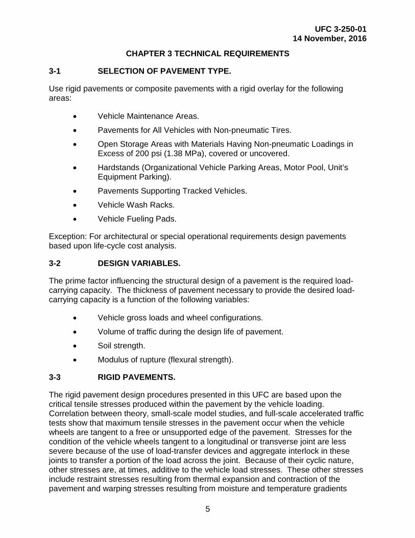
3-1 SELECTION OF PAVEMENT TYPE.
Use rigid pavements or composite pavements with a rigid overlay for the following areas:
• Vehicle Maintenance Areas.
• Pavements for All Vehicles with Non-pneumatic Tires.
• Open Storage Areas with Materials Having Non-pneumatic Loadings in Excess of 200 psi (1.38 MPa), covered or uncovered.
• Hardstands (Organizational Vehicle Parking Areas, Motor Pool, Unit’s Equipment Parking).
• Pavements Supporting Tracked Vehicles.
• Vehicle Wash Racks.
• Vehicle Fueling Pads.
Exception: For architectural or special operational requirements design pavements based upon life-cycle cost analysis.
3-2 DESIGN VARIABLES.
The prime factor influencing the structural design of a pavement is the required load-carrying capacity. The thickness of pavement necessary to provide the desired load-carrying capacity is a function of the following variables:
• Vehicle gross loads and wheel configurations.
• Volume of traffic during the design life of pavement.
• Soil strength.
• Modulus of rupture (flexural strength).
3-3 RIGID PAVEMENTS.
The rigid pavement design procedures presented in this UFC are based upon the critical tensile stresses produced within the pavement by the vehicle loading. Correlation between theory, small-scale model studies, and full-scale accelerated traffic tests show that maximum tensile stresses in the pavement occur when the vehicle wheels are tangent to a free or unsupported edge of the pavement. Stresses for the condition of the vehicle wheels tangent to a longitudinal or transverse joint are less severe because of the use of load-transfer devices and aggregate interlock in these joints to transfer a portion of the load across the joint. Because of their cyclic nature, other stresses are, at times, additive to the vehicle load stresses. These other stresses include restraint stresses resulting from thermal expansion and contraction of the pavement and warping stresses resulting from moisture and temperature gradients

UFC 3-250-01 14 November, 2016
6
within the pavement. Provision for those stresses not induced by wheel loads is included in design factors developed empirically from full-scale accelerated traffic tests and from the observed performance of pavements under actual service conditions.
3-4 FLEXIBLE PAVEMENTS.
The design procedure used by DoD to design flexible pavements for roads and parking areas is referred to as the Beta Criteria design procedure. This procedure requires that each layer be thick enough to distribute the stresses induced by traffic so that when such stresses reach the underlying layer they will not overstress the underlying layer causing excessive shear deformation. The Beta Criteria is used to sketch the design curves contained in Appendix E. Besides the determination of layer thicknesses, adequately compact each layer so that traffic does not induce excessive settlement. Use ASTM D1557 compaction effort procedures to design against consolidation under traffic.
3-5 MANDATORY USE OF PCASE.
PCASE is mandatory for the design of roads and parking areas trafficked by special military vehicles and for all vehicle types outside of the United States and its territories and possessions. Refer to UFC 3-201-01 for the types of vehicles characterized as special military vehicles.
PCASE is also mandatory for the design of organizational vehicle parking areas.
3-5.1 Pavement-Transportation Computer Assisted Structural Engineering.
PCASE is a computer program developed by the United States Army Corps of Engineers (USACE), Engineer Research and Development Center (ERDC), is available for use by the public. PCASE can be used to determine pavement thickness and compaction requirements. The computer program runs on the Microsoft Windows™ operating systems or Windows™ compatible systems. PCASE may be obtained electronically from the following:
• https://transportation.wes.army.mil/pcase or http://www.pcase.com
• A compact disk (CD) is also available from the U.S. Army Corps of Engineers, Transportation Systems Center, 1616 Capitol Avenue, Omaha, NE 68102-4901.
3-6 MATERIALS.
Materials for pavements designed in accordance with this UFC and PCASE must conform to requirements set forth in this and the Unified Facility Guide Specifications (UFGS). To the greatest practical extent, specify local materials that meet requirements of the Department of Transportation in the State in which the project is located, and are in accordance to UFC requirements. Only the materials should be changed in the UFGS, all other requirements such as general requirements, tolerances, and execution requirements should stay the same. The construction materials for pavements designed using state Department of Transportation (DoT) thickness design criteria must

UFC 3-250-01 14 November, 2016
7
conform to the DoT material specifications. The construction execution procedure for physically determining acceptable conditions, preparation, installation, field quality control and inspection must conform to the UFGS.
3-7 DRAINAGE SYSTEMS.
Pavement subdrainage systems are covered in this UFC. Refer to UFC 3-201-01 for criteria on storm drainage systems (e.g. surface drainage, underground drainage systems, stormwater management facilities, erosion and sediment control). Refer to UFC 3-210-01 for criteria on low impact development.

UFC 3-250-01 14 November, 2016
8
This Page Intentionally Left Blank

UFC 3-250-01 14 November, 2016
9
CHAPTER 4 PAVEMENT DESIGN
For the design of pavements traveled by standard American Association of State Highway and Transportation Officials (AASHTO) vehicles or vehicles not characterized as special military vehicles in UFC 3-201-01, in the United States, the State pavement design procedure may be used, except that the use of keyed joint, if allowed by the State, must not be used on pavement thinner than 9 inches. When using the State pavement design procedure, use the pavement design criteria and procedures recognized by the Department of Transportation (DoT) in the state in which the project is located. Refer to UFC 3-201-01, paragraph titled “Design Traffic” to predict average daily traffic (ADT) when using a State pavement design procedure.
4-1 EFFECT OF VEHICULAR TRAFFIC ON PAVEMENT DESIGN.
Design pavement thickness to withstand the anticipated traffic, categorized by type and weight of vehicles, and number of passes of each type for the design life of the pavement. For most pavements, the magnitude of the axle load is of greater importance than the gross weight of pneumatic-tired vehicles because axle spacing is generally so large that there is little interaction between the wheel loads of one axle and the wheel loads of the other axles. Thus, for the case of pneumatic-tired vehicles having equal axle loads, the increased severity of loading imposed by conventional four or five axle trucks as compared with that imposed by two or three axle trucks is largely a fatigue effect resulting from an increased number of load repetitions per vehicle operation. For forklift trucks where the loading is concentrated largely on a single axle and for tracked vehicles where the loading is evenly divided between the two tracks, the severity of the vehicle loading is a function of the gross weight of the vehicle and the frequency of loading. Relations between load repetition and required rigid pavement thickness developed from accelerated traffic tests of full-scale pavements have shown that, for any given vehicle, increasing the gross weight by as little as 10 percent can be equivalent to increasing the volume of traffic by as much as 300 to 400 percent. Therefore, for rigid pavements, the magnitude of the vehicle loading must be used as a more significant factor in the design of pavements than the number of load repetitions.
4-2 EQUIVALENT SINGLE AXLE LOAD (ESAL).
The ESAL used in this UFC is not the ESAL as computed by the AASHTO Guide for Design of Pavement Structures. In PCASE, the equivalency used is based on mixed traffic and the CBR Beta design model. Direct comparison or equivalence between AASHTO and PCASE ESAL is not straightforward since the ESAL computation in each methodology derives from specific models, assumptions, and design procedures. The conversion of each vehicle to ESALs is based on research done by the USACE, ERDC.
4-3 PAVEMENT DESIGN.
Unless specified otherwise in the project specific requirements, design pavement based upon anticipated vehicles and loadings for a 25 year life; however, sections must not be less than the minimums indicated in UFC 3-201-01. Pavements design is based on loads and the total number of passes during the life of the pavement for the expected vehicles. Typically, traffic is counted in terms of ADT. This ADT value should take into
UFC 3-250-01 14 November, 2016
10
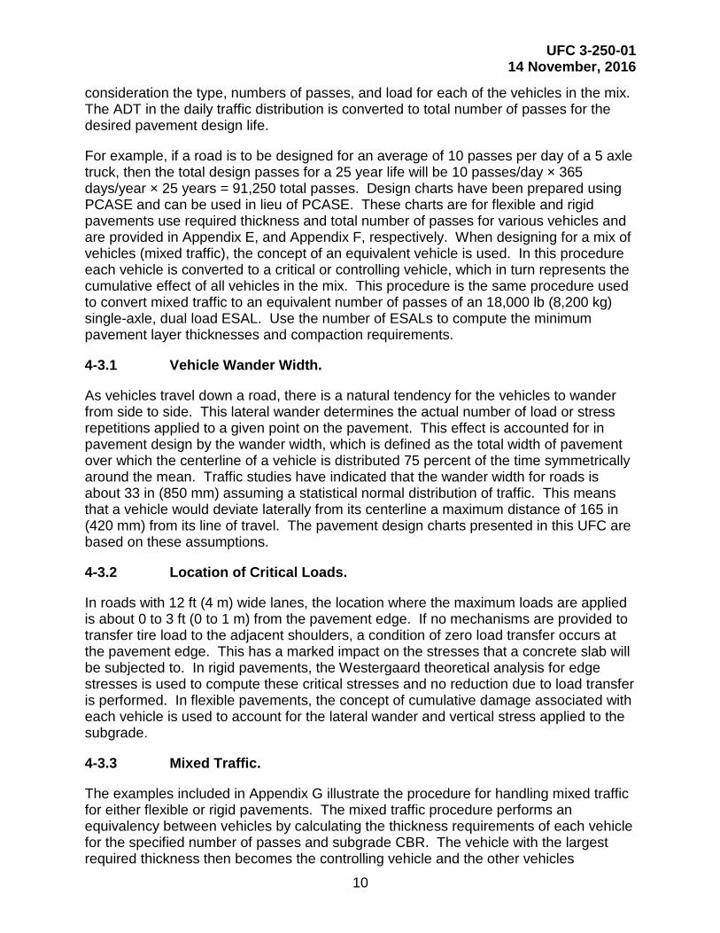
consideration the type, numbers of passes, and load for each of the vehicles in the mix. The ADT in the daily traffic distribution is converted to total number of passes for the desired pavement design life.
For example, if a road is to be designed for an average of 10 passes per day of a 5 axle truck, then the total design passes for a 25 year life will be 10 passes/day × 365 days/year × 25 years = 91,250 total passes. Design charts have been prepared using PCASE and can be used in lieu of PCASE. These charts are for flexible and rigid pavements use required thickness and total number of passes for various vehicles and are provided in Appendix E, and Appendix F, respectively. When designing for a mix of vehicles (mixed traffic), the concept of an equivalent vehicle is used. In this procedure each vehicle is converted to a critical or controlling vehicle, which in turn represents the cumulative effect of all vehicles in the mix. This procedure is the same procedure used to convert mixed traffic to an equivalent number of passes of an 18,000 lb (8,200 kg) single-axle, dual load ESAL. Use the number of ESALs to compute the minimum pavement layer thicknesses and compaction requirements.
4-3.1 Vehicle Wander Width.
As vehicles travel down a road, there is a natural tendency for the vehicles to wander from side to side. This lateral wander determines the actual number of load or stress repetitions applied to a given point on the pavement. This effect is accounted for in pavement design by the wander width, which is defined as the total width of pavement over which the centerline of a vehicle is distributed 75 percent of the time symmetrically around the mean. Traffic studies have indicated that the wander width for roads is about 33 in (850 mm) assuming a statistical normal distribution of traffic. This means that a vehicle would deviate laterally from its centerline a maximum distance of 165 in (420 mm) from its line of travel. The pavement design charts presented in this UFC are based on these assumptions.
4-3.2 Location of Critical Loads.
In roads with 12 ft (4 m) wide lanes, the location where the maximum loads are applied is about 0 to 3 ft (0 to 1 m) from the pavement edge. If no mechanisms are provided to transfer tire load to the adjacent shoulders, a condition of zero load transfer occurs at the pavement edge. This has a marked impact on the stresses that a concrete slab will be subjected to. In rigid pavements, the Westergaard theoretical analysis for edge stresses is used to compute these critical stresses and no reduction due to load transfer is performed. In flexible pavements, the concept of cumulative damage associated with each vehicle is used to account for the lateral wander and vertical stress applied to the subgrade.
4-3.3 Mixed Traffic.
The examples included in Appendix G illustrate the procedure for handling mixed traffic for either flexible or rigid pavements. The mixed traffic procedure performs an equivalency between vehicles by calculating the thickness requirements of each vehicle for the specified number of passes and subgrade CBR. The vehicle with the largest required thickness then becomes the controlling vehicle and the other vehicles

UFC 3-250-01 14 November, 2016
11
converted to it by the procedure described in the examples. The calculations are based on the thickness requirements of each individual vehicle; therefore the resulting controlling vehicle for flexible and rigid pavements may be different. Since subgrade conditions may vary along a road, mixed traffic calculations use a representative subgrade strength category instead of a specific value. These representative subgrade categories are shown in Table 4-1. However, when the final mixed traffic equivalency has been finished in terms of the equivalent passes of the controlling vehicle, the design CBR or k value will be used to obtain the required pavement thickness above the subgrade.
Table 4-1 Representative Subgrade Categories
Subgrade Category
Flexible Pavements, CBR Range
Representative CBR Value
Rigid Pavements k-value Range
psi/in1 Representative k-value, psi/in1
A CBR ≥ 13 15 k ≥ 442 552.6 B 8 < CBR <13 10 221 < k < 442 294.7 C 4 < CBR ≤ 8 6 92 < k ≤ 221 147.4 D CBR ≤ 4 3 k ≤ 92 73.7
1 kPa/mm = psi/in ÷ 0.271

UFC 3-250-01 14 November, 2016
12
This Page Intentionally Left Blank

UFC 3-250-01 14 November, 2016
13
CHAPTER 5 FLEXIBLE PAVEMENT SUBGRADES
5-1 FACTORS TO BE CONSIDERED.
Consider the following primary factors regarding subgrades for flexible pavement design:
• The general characteristics of the subgrade soils (e.g. soil classification, limits).
• Depth to bed rock.
• Depth to groundwater table (including perched groundwater table).
• The attainable compaction in the subgrade and the adequacy of the existing density in the layers below the zone of compaction requirements
• The CBR that the compacted subgrade and un-compacted subgrade will have under local environmental conditions.
• The presence of weak soft layers in the subsoil.
• Susceptibility to detrimental frost action.
• Expansion potential
5-2 COMPACTION.
The natural density of the subgrade must be sufficient to resist densification under traffic or the subgrade must be compacted during construction to a depth where the natural density will resist densification under traffic. Table 5-1 shows the depth, measured from the pavement surface, at which a given percent compaction is required to prevent densification under traffic. Subgrades in cuts must have natural densities equal to or greater than the values shown in Table 5-1. Where such is not the case, compact the subgrade from the surface to meet the tabulated densities, or remove and replace the subgrade, in which case the requirements for fills apply. As another option, cover the subgrade with sufficient selected material, subbase, and base so that the un-compacted subgrade is at a depth where the in place densities are satisfactory. In fill areas, place cohesionless soils at no less than 95 percent of ASTM D1557 maximum density and cohesive fills at less than 90 percent of ASTM D1557 maximum density.

UFC 3-250-01 14 November, 2016
14
Table 5-1 Depth of Compaction for Select Materials and Subgrades (CBR1 ≤ 20)
Equivalent Passes of an 18,000-lb (8,200-kg) ESAL Depth of Compaction2 or Percent Compaction Shown, in
Type of Pavement Cohesive Soils PI>5; LL>25 Cohesionless Soils PI≤ 5, LL≤ 25
Flexible Rigid 100 95 90 85 80 100 95 90 85 80 < 15,500 < 1,300 3 7 10 14 17 7 13 19 25 33 < 67,500 < 1,500 4 8 12 16 20 8 15 22 29 38 < 295,000 < 34,000 4 9 14 18 23 9 17 25 33 43
< 1.3 million < 343,000 5 11 16 21 26 11 20 28 37 48 < 5.7 million < 2.1 million 6 12 18 23 28 12 22 31 40 53 < 25 million < 9.2 million 7 14 19 25 31 14 24 35 44 58 < 112 million < 37 million 7 15 21 28 34 15 26 38 48 63 < 500 million < 105 million 8 16 23 30 37 16 29 41 52 68
< 2,200 million < 290 million 9 18 25 32 40 18 31 44 56 74 ≥ 2,200 million ≥ 290 millions 10 20 28 35 43 20 34 47 59 77
1 California Bearing Ratio (ASTM D4429). 2 Depth of compaction is measured from pavement surface.
5-3 COMPACTION EXAMPLES.
Appendix G includes two examples illustrating the application of subgrade compaction requirements 5-4 SELECTION OF DESIGN CBR VALUES.
Flexible pavements may be designed using the laboratory soaked CBR, the field in-place CBR, the CBR from the Dynamic Cone Penetrometer as described in ASTM D6951/D6951M or the CBR from undisturbed samples as described in ASTM D1883 or ASTM D 4429. For the design of flexible pavements in areas where no previous experience regarding pavement performance is available, the laboratory soaked CBR is normally used. Where an existing pavement is available at the site that has a subgrade constructed to the same standards as the job being designed, in-place tests or tests on undisturbed samples may be used in selecting the design CBR value. In-place tests are used when the subgrade material is at the maximum water content expected in the prototype and frost is not expected to penetrate the subgrade. Contrarily, tests on undisturbed samples are used where the material is not at the maximum water content and thus soaking is required. Sampling involves considerably more work than in-place tests and undisturbed samples tend to be slightly disturbed. Therefore, in-place tests should be used where possible. Guides for determining when in-place tests can be used are given in details of the CBR test in ASTM D4429.
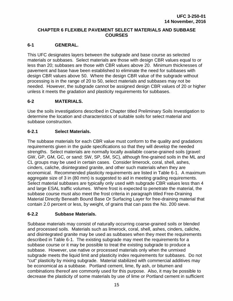
UFC 3-250-01 14 November, 2016
15
CHAPTER 6 FLEXIBLE PAVEMENT SELECT MATERIALS AND SUBBASE COURSES
6-1 GENERAL.
This UFC designates layers between the subgrade and base course as selected materials or subbases. Select materials are those with design CBR values equal to or less than 20; subbases are those with CBR values above 20. Minimum thicknesses of pavement and base have been established to eliminate the need for subbases with design CBR values above 50. Where the design CBR value of the subgrade without processing is in the range of 20 to 50, select materials and subbases may not be needed. However, the subgrade cannot be assigned design CBR values of 20 or higher unless it meets the gradation and plasticity requirements for subbases.
6-2 MATERIALS.
Use the soils investigations described in Chapter titled Preliminary Soils Investigation to determine the location and characteristics of suitable soils for select material and subbase construction.
6-2.1 Select Materials.
The subbase materials for each CBR value must conform to the quality and gradations requirements given in the guide specifications so that they will develop the needed strengths. Select materials are normally locally available coarse-grained soils (gravel: GW, GP, GM, GC, or sand: SW, SP, SM, SC), although fine-grained soils in the ML and CL groups may be used in certain cases. Consider limerock, coral, shell, ashes, cinders, caliche, disintegrated granite, and other such materials when they are economical. Recommended plasticity requirements are listed in Table 6-1. A maximum aggregate size of 3 in (80 mm) is suggested to aid in meeting grading requirements. Select material subbases are typically only used with subgrade CBR values less than 4 and large ESAL traffic volumes. Where frost is expected to penetrate the material, the subbase course must also meet the frost criteria in paragraph titled Free-Draining Material Directly Beneath Bound Base Or Surfacing Layer for free-draining material that contain 2.0 percent or less, by weight, of grains that can pass the No. 200 sieve.
6-2.2 Subbase Materials.
Subbase materials may consist of naturally occurring coarse-grained soils or blended and processed soils. Materials such as limerock, coral, shell, ashes, cinders, caliche, and disintegrated granite may be used as subbases when they meet the requirements described in Table 6-1. The existing subgrade may meet the requirements for a subbase course or it may be possible to treat the existing subgrade to produce a subbase. However, use native or processed materials only when the unmixed subgrade meets the liquid limit and plasticity index requirements for subbases. Do not “cut” plasticity by mixing subgrade. Material stabilized with commercial additives may be economical as a subbase. Portland cement, lime, fly ash, or bitumen and combinations thereof are commonly used for this purpose. Also, it may be possible to decrease the plasticity of some materials by use of lime or Portland cement in sufficient

UFC 3-250-01 14 November, 2016
16
amounts to make them suitable as subbases. When using ash or cinders, the free lime content must be less than 5% and the material must be volumetrically stable.
6-3 COMPACTION.
Compaction of subbases will be 100 percent of ASTM D1557 density except where it is known that a higher density can be obtained, in which case the higher density should be required. Compaction of select materials and subgrades will be as shown in Table 5-1 except that in no case will cohesionless fill be placed at less than 95 percent or cohesive fill at less than 90 percent.
6-4 DRAINAGE.
Subbase drainage is an important aspect of design and is discussed in Chapter titled Design of Subsurface Pavement Drainage Systems.
6-5 SELECTION OF DESIGN CBR VALUES.
During the design phase where the materials have normally not been selected for construction, the design CBR values should be selected based on the gradations recommended in Table 6-1 and the cost of the materials available. The select material or subbase is generally uniform, and the problem of selecting a limiting condition, as described for the subgrade, does not ordinarily exist. Tests are usually made on remolded samples; however, where existing similar construction is available, CBR tests may be made in place on material when it has attained its maximum expected water content or on undisturbed soaked samples. The procedures for selecting CBR design values described for subgrades apply to select materials and subbases. CBR tests on gravelly materials in the laboratory tend to give CBR values higher than those obtained in the field. The difference is attributed to the processing necessary to test the sample in the 6 in (150 mm) mold, and to the confining effect of the mold. Therefore, the CBR test is supplemented by gradation and Atterberg limits requirements for subbases, as shown in Table 6-1. Suggested limits for select materials are also indicated. In addition to these requirements, the material must also show in the laboratory tests a CBR equal to or higher than the CBR assigned to the material for design purposes.
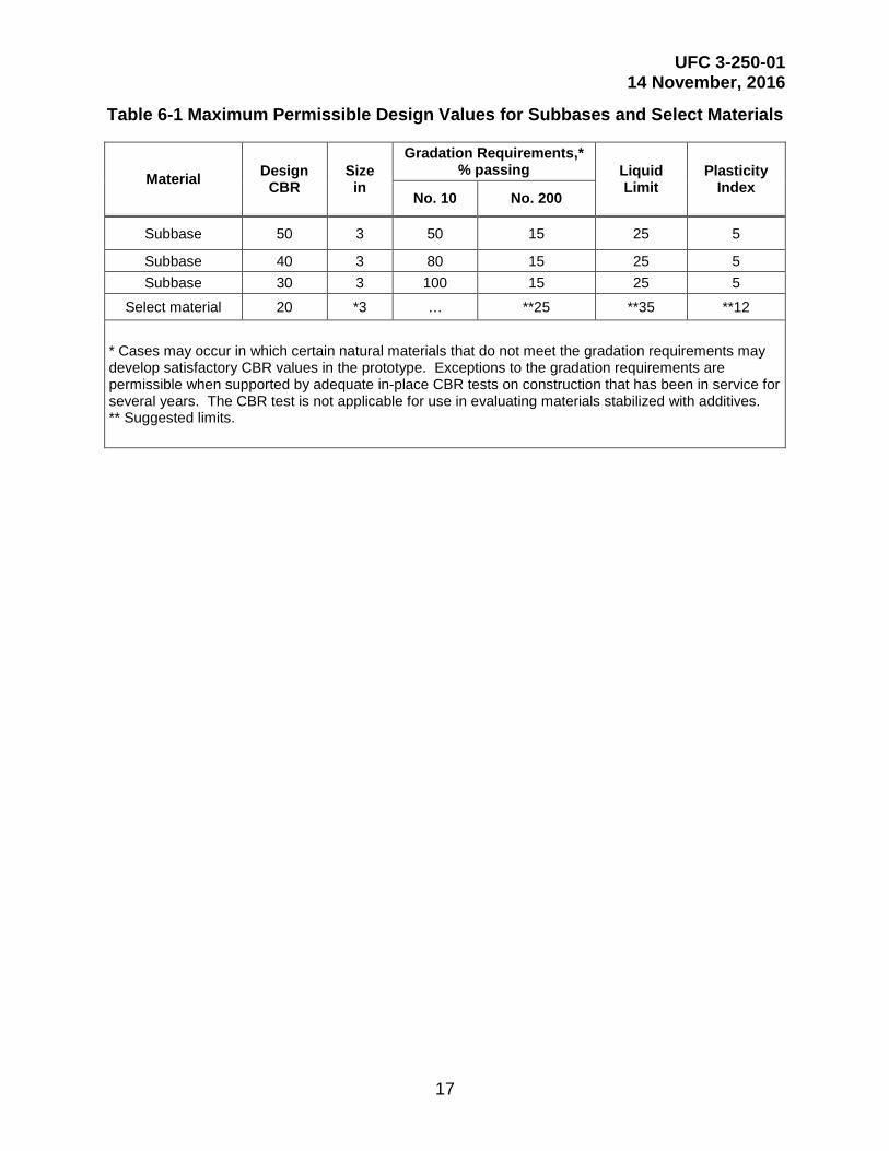
UFC 3-250-01 14 November, 2016
17
Table 6-1 Maximum Permissible Design Values for Subbases and Select Materials
Material Design CBR
Size in
Gradation Requirements,* % passing Liquid
Limit Plasticity
Index No. 10 No. 200
Subbase 50 3 50 15 25 5
Subbase 40 3 80 15 25 5 Subbase 30 3 100 15 25 5
Select material 20 *3 … **25 **35 **12
* Cases may occur in which certain natural materials that do not meet the gradation requirements may develop satisfactory CBR values in the prototype. Exceptions to the gradation requirements are permissible when supported by adequate in-place CBR tests on construction that has been in service for several years. The CBR test is not applicable for use in evaluating materials stabilized with additives. ** Suggested limits.

UFC 3-250-01 14 November, 2016
18
This Page Intentionally Left Blank

UFC 3-250-01 14 November, 2016
19
CHAPTER 7 FLEXIBLE PAVEMENT BASE COURSES
7-1 MATERIALS.
Use high-quality materials in base courses of flexible pavements. These high-quality materials provide resistance to the high stresses that occur near the pavement surface. Guide specifications for graded crushed aggregate, limerock, and stabilized aggregate may be used without qualification for design of roads and parking areas. Guide specifications for dry- and water-bound macadam base courses may be used for design of pavements only when the cost of the dry- or water-bound macadam base does not exceed the cost of stabilized-aggregate base course, and the ability of probable bidders to construct pavements with dry- or water-bound macadam base to the required surface smoothness and grade tolerances has been proved by experience in the area.
7-2 COMPACTION.
Compact base courses for flexible pavements sections to the maximum density practicable, but never less than 100 percent of ASTM D1557 maximum density. Generally, the base course will be compacted to a minimum of 100 percent of ASTM D1557 maximum density.
7-3 DRAINAGE.
Drainage design for base courses is discussed in Chapter titled Design of Subsurface Pavement Drainage Systems.
7-4 SELECTION OF DESIGN CBR.
Because of the effects of processing samples for the laboratory CBR tests and because of the effects of the test mold, do not use the laboratory CBR test to determine CBR values of base courses. Instead, assign selected CBR ratings as shown in Table 7-1. These ratings have been based on service behavior records and, where pertinent, on in-place tests made on materials subjected to traffic. Materials must conform to the quality requirements given in the guide specifications to develop the needed strengths. To obtain an 80 CBR for No. 6 Aggregate Base Coarse, the material must have 50 percent crushed particles and be graded, but the No. 1 Graded-Crushed Aggregate Base Coarse material has a higher 90 percent of crushed material.
7-5 MINIMUM THICKNESS.
Refer to UFC 3-201-01 for minimum thickness requirements where the State pavement design procedure is used. Where the use of PCASE is mandatory, the minimum allowable thickness of base course is shown in Table 7-2. The total thickness of pavement plus base for roads and parking areas must not be less than 6 in (150 mm) or the frost penetration depth as determined from Chapter titled Seasonal Frost Conditions except where a surface treatment is applied. Where frost is expected to penetrate the base material, the base course must also meet the frost criteria in paragraph titled Free-Draining Material Directly Beneath Bound Base Or Surfacing Layer for free-draining material that contain 2.0 percent or less, by weight, of grains that can pass the No. 200

UFC 3-250-01 14 November, 2016
20
sieve. The drainage criteria in Chapter titled Design of Subsurface Pavement Drainage Systems, requires a minimum of 4 in (100 mm) of drainage layer and 4 in (100 mm) of subbase (separation) course for most pavements. When a pavement design requires 12 in (300 mm) or more of granular material above the subgrade, add base course. For pavements requiring less than 12 in (300 mm) of granular material above the subgrade, evaluate the drainage requirements in Chapter titled Design of Subsurface Pavement Drainage Systems to determine a cost effective system of granular materials. Placing an asphalt surface directly on a drainage layer (without a base course) can be accomplished under certain conditions.
Table 7-1 Design CBR Values
No. Type Design CBR
1 Graded crushed aggregate 100
2 Water-bound macadam 100
3 Dry-bound macadam 100
4 Bituminous binder and surface courses, central plant, hot mix 100
5 Limerock 80
6 Aggregate 80
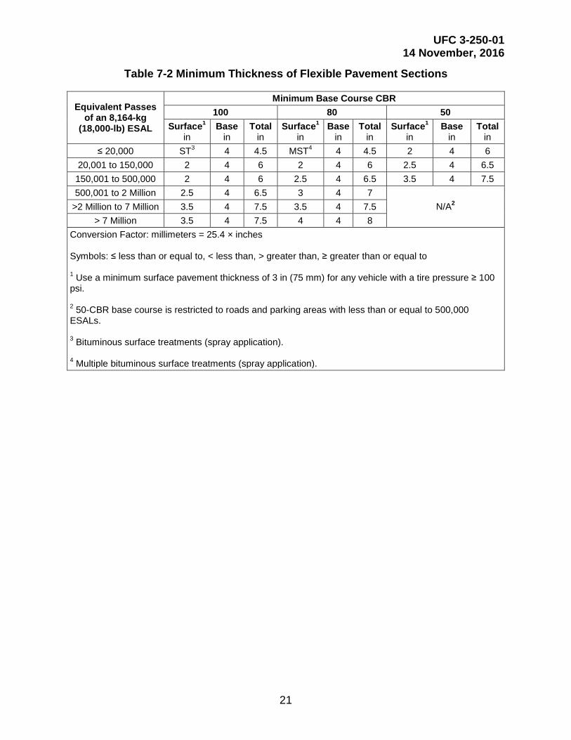
UFC 3-250-01 14 November, 2016
21
Table 7-2 Minimum Thickness of Flexible Pavement Sections
Equivalent Passes of an 8,164-kg
(18,000-lb) ESAL
Minimum Base Course CBR 100 80 50
Surface1 in
Base in
Total in
Surface1 in
Base in
Total in
Surface1 in
Base in
Total in
≤ 20,000 ST3 4 4.5 MST4 4 4.5 2 4 6 20,001 to 150,000 2 4 6 2 4 6 2.5 4 6.5 150,001 to 500,000 2 4 6 2.5 4 6.5 3.5 4 7.5 500,001 to 2 Million 2.5 4 6.5 3 4 7
N/A2 >2 Million to 7 Million 3.5 4 7.5 3.5 4 7.5 > 7 Million 3.5 4 7.5 4 4 8
Conversion Factor: millimeters = 25.4 × inches Symbols: ≤ less than or equal to, < less than, > greater than, ≥ greater than or equal to 1 Use a minimum surface pavement thickness of 3 in (75 mm) for any vehicle with a tire pressure ≥ 100 psi. 2 50-CBR base course is restricted to roads and parking areas with less than or equal to 500,000 ESALs. 3 Bituminous surface treatments (spray application). 4 Multiple bituminous surface treatments (spray application).

UFC 3-250-01 14 November, 2016
22
This Page Intentionally Left Blank

UFC 3-250-01 14 November, 2016
23
CHAPTER 8 BITUMINOUS PAVEMENT
8-1 GENERAL.
The bituminous materials used in paving are asphaltic or tar products as listed in UFC 3-250-03. Although asphalts and tars resemble each other in general appearance, they do not have the same physical or chemical characteristics. Tars are affected to a greater extent by temperature changes and weather conditions; however, they tend to have better adhesive and penetrating properties than asphalts. Generally, asphalt surface courses are preferred to tar surface courses. The selection of the type of bituminous material (asphalt or tar) should normally be based on economy.
8-2 CRITERIA FOR BITUMINOUS PAVEMENTS.
The basic criteria for selection and design of bituminous pavements are contained in UFC 3-250-03 which includes the following criteria:
• Selection of bitumen type;
• Selection of bitumen grade;
• Aggregate requirements;
• Quality requirements;
• Types of bituminous pavements. 8-3 MINIMUM THICKNESS.
Refer to UFC 3-201-01 for minimum thickness requirements where the State pavement design procedure is used. Where the use of PCASE is mandatory, the minimum thickness of bituminous materials varies with the strength of the underlying base course and is given in Table 7-2.

UFC 3-250-01 14 November, 2016
24
This Page Intentionally Left Blank

UFC 3-250-01 14 November, 2016
25
CHAPTER 9 FLEXIBLE PAVEMENT DESIGN
9-1 GENERAL.
Flexible pavement designs must provide the following:
• Sufficient compaction of the subgrade and of each layer during construction to prevent objectionable settlement under traffic.
• Adequate drainage of base course.
• Adequate thickness above the subgrade and above each layer together with adequate quality of the select material, subbase, and base courses to prevent detrimental shear deformation under traffic and, when frost conditions are a factor, to control or reduce to acceptable limits effects of frost heave or permafrost degradation.
• A stable, weather-resistant, wear-resistant waterproof, non-slippery pavement.
9-2 DESIGN PROCEDURE.
9-2.1 Conventional Flexible Pavements.
In designing conventional flexible pavement structures, apply the design values assigned to the various layers to the curves and criteria presented in this UFC. As several designs are generally possible for a specific site, select the most practical and economical design meeting the minimum design requirements. Since the decision on the practicability of a particular design may be largely a matter of judgment, include full particulars regarding the selection of the final design (including cost estimates) in the design analysis.
Refer to UFC 3-201-01 for permeable pavement criteria.
9-2.2 Stabilized Soil Layers.
Flexible pavements containing stabilized soil layers are designed through the use of equivalency factors. A conventional flexible pavement is first designed and the equivalency factors applied to the thickness of the layer to be stabilized. When stabilized materials meeting all gradation, durability, and strength requirements indicated in UFC 3-250-11, and Chapter titled Seasonal Frost Conditions are used in pavement structures, an appropriate equivalency factor may be applied. Soils which have been mixed with a stabilizing agent and which do not meet the requirements for a stabilized soil are considered modified and are designed as conventional pavement layers. When Portland cement is used to stabilize base course materials in DoD pavements, the treatment level must be maintained below about 4 percent by weight to minimize shrinkage cracking which will reflect through the bituminous concrete surface course. In this case, the base course will, in most instances, be modified rather than stabilized. In addition, when unbound granular layers are used between two bound layers (e.g., an unbound base course between an asphalt concrete (AC) surface course
UFC 3-250-01 14 November, 2016
26
and a stabilized subbase course), provide adequate drainage to the unbound layer to prevent entrapment of excessive moisture in the layer. Additional criteria on soil stabilization may be obtained from UFC 3-250-11.
9-2.3 All-Bituminous Concrete.
All-bituminous concrete pavements are also designed using equivalency factors. See paragraph titled Equivalency Factors below. The procedure is the same as for stabilized soil layers discussed above.
9-3 DESIGN TRAFFIC.
The design of flexible pavements for roads and parking areas will be based on the actual traffic expected to use a flexible pavement during its service life and the procedures described in Chapter titled Vehicular Traffic. The designer is cautioned that in selecting the design traffic, consideration must be given to traffic which may use the pavement structure during various stages of construction and to other foreseeable exceptional use.
9-4 THICKNESS CRITERIA FOR CONVENTIONAL FLEXIBLE PAVEMENTS.
For roads and parking areas, obtain the required thickness of flexible pavements from the design charts presented in Appendix E. The charts in Appendix E were developed using thickness design requirements and are given in terms of subgrade CBR. If the design includes vehicles not covered Appendix E, PCASE must be used. Minimum thickness requirements are shown in Table 7-2. For frost condition design, thickness requirements will be determined from Chapter titled Seasonal Frost. In regions where the annual precipitation is less than 15 in (380 mm) and the groundwater table (including perched groundwater table) is at least 15 ft (4.6 m) below the finished pavement surface, the danger of high moisture content in the subgrade is reduced. Where in-place tests on similar construction in these regions indicate that the water content of the subgrade will not increase above the optimum, the total pavement thickness, as determined by CBR tests on soaked samples, may be reduced by as much as 20 percent. The minimum thickness of pavement and subbase must still be met; therefore the reduction will be affected in the subbase course immediately above the subgrade. When only limited rainfall records are available, or the annual precipitation is close to the 15 inch criterion, give careful consideration to the sensitivity of the subgrade to small increases in moisture content before any reduction in thickness is made.
Appendix G includes an example of thickness design for conventional flexible pavements.

UFC 3-250-01 14 November, 2016
27
9-5 THICKNESS CRITERIA-STABILIZED SOIL LAYERS.
9-5.1 Equivalency Factors.
The use of stabilized soil layers within a flexible pavement provides the opportunity to reduce the overall thickness of pavement structure required to support a given load. The design of pavement containing stabilized soil layers requires the application of equivalency factors to a layer or layers of a conventionally designed pavement. To qualify for application of equivalency factors, the stabilized layer must meet appropriate strength and durability requirements set forth in UFC 3-250-11. An equivalency factor represents the number of inches (millimeters) of a conventional base or subbase which can be replaced by 1 in (25 mm) of stabilized material. Equivalency factors for stabilized materials are determined as shown in Table 9-1. The cement content must be limited to 4 percent by weight or less to prevent excessive reflective cracking. Selection of an equivalency factor from the tabulation is dependent upon the classification of the soil to be stabilized.
Table 9-1 Equivalency Factors for Stabilized Material
Material Equivalency Factors
Base Subbase Asphalt-stabilized All-bituminous concrete 1.15 2.30 GW, GP, GM, GC 1.00 2.00 SW, SP, SM, SC * 1.50 Cement-stabilized GW, GP, SW, SP 1.15 2.30 GM, GC 1.00 2.00 ML, MH, CL, CH * 1.70 SC, SM * 1.50 Lime-stabilized ML, MH, CL, CH * 1.00 SC, SM, GM, GC * 1.10 Lime, Cement, Fly ash Stabilized ML, MH, CL, CH * 1.30 SC, SM, GM, GC * 1.40 Unbound crushed stone 1.00 2.00 Unbound aggregate * 1.00 * Not used for base course material.
9-5.2 Minimum Thickness.
Apply the minimum thickness requirements to the standard pavement before determining the stabilized layer thicknesses. However for pavements with stabilized layers, the minimum thickness requirement for the asphalt layer is the same as shown in Table 7-1 for conventional pavements.
UFC 3-250-01 14 November, 2016
28
9-6 EXAMPLE THICKNESS DESIGN-STABILIZED SOIL LAYERS.
The equivalency factors require that a conventional flexible pavement be designed to support the design load conditions. If it is desired to use a stabilized base or subbase course, divide the thickness of conventional base or subbase by the equivalency factor for the applicable stabilized soil. Two examples for the application of the equivalency factors are included in Appendix G.
9-7 SHOULDERS AND SIMILAR AREAS.
These areas are provided only for the purpose of minimizing damage to vehicles which use them accidentally or in emergencies; therefore, they are not considered normal vehicular traffic areas. Provide paved shoulders for high volume roads. Others will be surfaced with soils selected for their stability in wet weather and will be compacted as required. Dust and erosion control will be provided by vegetative cover, anchored mulch, coarse-graded aggregate or liquid palliatives UFC 3-260-17. Shoulders will not block base course drainage, particularly where frost conditions are a factor.
9-8 BITUMINOUS SIDEWALKS, CURBS, AND GUTTERS.
Refer to UFC 3-201-01 for criteria on bituminous sidewalks, curbs and gutters.
9-9 FLEXIBLE OVERLAY DESIGN.
For the design of flexible pavement overlays, see Chapter titled Pavement Overlays.
9-10 FLEXIBLE PAVEMENT DESIGN CURVES.
Appendix E contains the flexible pavement design curves of vehicles commonly included in the design traffic mix. If a design curve for a vehicle not included in Appendix E, the U.S. Army Corps of Engineers, Transportation Systems Center, 1616 Capitol Avenue, Omaha, NE 68102-4901 may be contacted.

UFC 3-250-01 14 November, 2016
29
CHAPTER 10 RIGID PAVEMENT DESIGN
10-1 SOIL CLASSIFICATION AND TESTS.
All soils should be classified according to the USCS as given in ASTM D2487. There have been instances in construction specifications where the use of such terms as "loam," "gumbo," "mud," and "muck" have resulted in misunderstandings. These terms are not specific and are subject to different interpretations throughout the United States. Such terms should not be used. Sufficient investigations should be performed at the proposed site to facilitate the description of all soils that will be used or removed during construction in accordance with ASTM D 2487; any additional descriptive information considered pertinent should also be included. If Atterberg limits are a required part of the description, as indicated by the classification tests, the test procedures and limits should be referenced in the construction specifications.
10-2 COMPACTION.
10-2.1 General.
Compaction improves the stability of the subgrade soils and provides a more uniform foundation for the pavement. The ASTM D1557 soil compaction test conducted at several moisture contents is used to determine the compaction characteristics of the subgrade soils. The range of maximum densities normally obtained in the compaction test on various soil types is listed in UFC 3-260-02. This test method should not be used if the soil contains particles that are easily broken under the blow of the tamper unless the field method of compaction will produce a similar degradation. Certain types of soil may require the use of a laboratory compaction control test other than the soil compaction test. The unit weight of some types of sands and gravels obtained using the compaction method above may be lower than the unit weight that can be obtained by field compaction; hence, the method may not be applicable. In those cases where a higher laboratory density is desired, compaction tests are usually made under some variation of the ASTM D1557 method, such as vibration or tamping (alone or in combination) with a type hammer or compaction effort different from that used in the test.
10-2.2 Requirements.
For all subgrade soil types, compact the subgrade under the pavement slab or base course to a minimum depth of 6 in (150 mm). If the densities of the natural subgrade materials are equal to or greater than 90 percent of the maximum density from ASTM D1557, no rolling is necessary other than that required to provide a smooth surface. Compaction requirements for cohesive soils (Liquid Limit (LL) > 25; Plasticity Index (PI) > 5) are 90 percent of maximum density for the top 6 in (150 mm) of cuts and the full depth of fills. Compaction requirements for cohesionless soils (LL<25: PI<5) are 95 percent for the top 6-in of cuts and the full depth of fills. Compaction of the top 6 in (150 mm) of cuts may require the subgrade to be scarified and dried or moistened as necessary and re-compacted to the desired density.
UFC 3-250-01 14 November, 2016
30
10-2.3 Special Soils.
Although compaction increases the stability and strength of most soils, some soil types show a marked decrease in stability when scarified, worked, and rolled. Also, expansive soils shrink excessively during dry periods and expand excessively when allowed to absorb moisture. When soils of these types are encountered, special treatment will usually be required. For nominally expansive soils, water content, compaction effort, and overburden should be determined to control swell. For highly expansive soils, replacement to depth of moisture equilibrium, raising grade, lime stabilization, pre-wetting, or other acceptable means of controlling swell should be considered.
10-3 TREATMENT OF UNSUITABLE SOILS.
Soils not suitable for subgrade use, as specified in UFC 3-260-02, should be removed and replaced, covered with soils which are suitable or treated. The depth to which such adverse soils should be removed, covered, or treated depends on the soil type, drainage conditions, and depth of freezing temperature penetration and should be determined by the engineer on the basis of judgment and previous experience, with due consideration of the traffic to be served and the costs involved. Where freezing temperatures penetrate a frost-susceptible subgrade, follow the design procedures outlined in Chapter titled Seasonal Frost Conditions. In some instances, unsuitable or adverse soils may be improved economically by stabilization with such materials as cement, fly ash, lime, or certain chemical additives, whereby the characteristics of the composite material become suitable for subgrade purposes. Criteria for soil stabilization are in UFC 3-250-11. However, subgrade stabilization should not be attempted unless the costs reflect corresponding savings in base course, pavement, or drainage facilities construction. Highly expansive subgrades are typically removed and replaced with suitable soil, compacted at a moisture content and unit weight that will minimize expansion, or chemically treated. Care should be taken when using calcium-based materials such as lime and Portland cement to chemically treat clay soils with soluble sulfates. The combination of calcium-based stabilizer, water, and clay with soluble sulfates will produce calcium-aluminate-sulfate-hydrate minerals with very large expansion potential. An adequate amount of water and mellowing time is required to allow formation of the expansive minerals before compaction.
10-4 DETERMINATION OF MODULUS OF SUBGRADE REACTION.
For the design of rigid pavements in those areas where no previous experience regarding pavement performance is available, determine the modulus of subgrade reaction k for design purposes by the field plate-bearing test. Where performance data from existing rigid pavements are available, adequate values for k can usually be determined on the basis of consideration of soil type, drainage conditions, and frost conditions that prevail at the proposed site. Table 10-1 presents typical values of k for various soil types and moisture conditions as a function of base course thickness. Consider these values as a guide only and their use in place of the field plate-bearing test, although not recommended, is left to the discretion of the engineer. Where a base course is used under the pavement, the k value on top of the base (also known as the
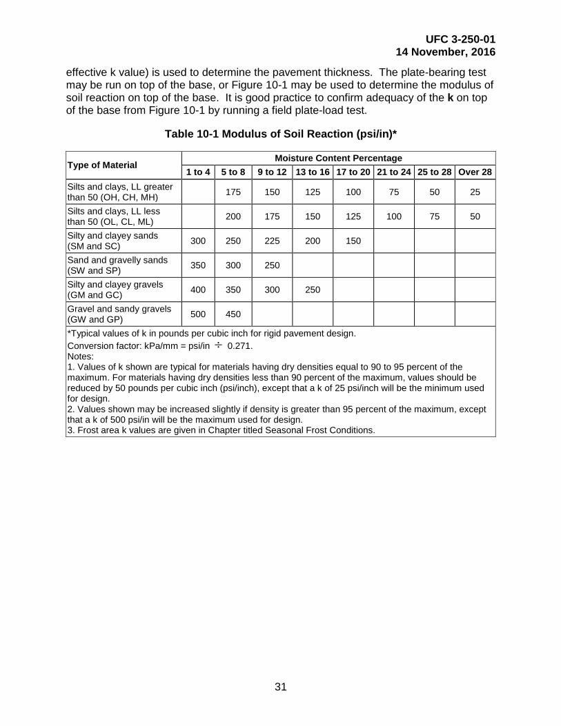
UFC 3-250-01 14 November, 2016
31
effective k value) is used to determine the pavement thickness. The plate-bearing test may be run on top of the base, or Figure 10-1 may be used to determine the modulus of soil reaction on top of the base. It is good practice to confirm adequacy of the k on top of the base from Figure 10-1 by running a field plate-load test.
Table 10-1 Modulus of Soil Reaction (psi/in)*
Type of Material Moisture Content Percentage
1 to 4 5 to 8 9 to 12 13 to 16 17 to 20 21 to 24 25 to 28 Over 28 Silts and clays, LL greater than 50 (OH, CH, MH) 175 150 125 100 75 50 25
Silts and clays, LL less than 50 (OL, CL, ML) 200 175 150 125 100 75 50
Silty and clayey sands (SM and SC) 300 250 225 200 150
Sand and gravelly sands (SW and SP) 350 300 250
Silty and clayey gravels (GM and GC) 400 350 300 250
Gravel and sandy gravels (GW and GP) 500 450
*Typical values of k in pounds per cubic inch for rigid pavement design. Conversion factor: kPa/mm = psi/in ÷ 0.271. Notes: 1. Values of k shown are typical for materials having dry densities equal to 90 to 95 percent of the maximum. For materials having dry densities less than 90 percent of the maximum, values should be reduced by 50 pounds per cubic inch (psi/inch), except that a k of 25 psi/inch will be the minimum used for design. 2. Values shown may be increased slightly if density is greater than 95 percent of the maximum, except that a k of 500 psi/in will be the maximum used for design. 3. Frost area k values are given in Chapter titled Seasonal Frost Conditions.
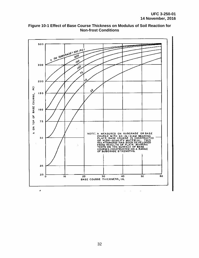
UFC 3-250-01 14 November, 2016
32
Figure 10-1 Effect of Base Course Thickness on Modulus of Soil Reaction for Non-frost Conditions

UFC 3-250-01 14 November, 2016
33
CHAPTER 11 RIGID PAVEMENT BASE COURSES
11-1 GENERAL REQUIREMENTS.
Base courses may be required under rigid pavements for replacing soft, highly compressible or expansive soils and for providing the following:
• Additional structural strength;
• More uniform bearing surface for the pavement;
• Protection for the subgrade against detrimental frost action;
• Drainage;
• Suitable surface for the operation of construction equipment, especially slip form pavers.
Use of base courses under a rigid pavement to provide structural benefit should be based on economy of construction. Thick base courses have often resulted in lower maintenance costs since the thick base course provides stronger foundation and therefore less slab movement. Provide a minimum base-course thickness of 4 in (100 mm) over subgrades that are classified as OH, CH, CL, MH, ML, and OL to provide protection against pumping. In certain cases of adverse moisture conditions (high groundwater table or poor drainage), SM and SC soils also may require base courses to prevent pumping. The designer is cautioned against the use of fine-grained material for leveling courses or choking open-graded base courses since this may create a pumping condition. Positive drainage should be provided for all base courses to ensure groundwater is not trapped directly beneath the pavement since saturation of these layers will cause the pumping condition that the base course is intended to prevent. The base course material and drains must meet the drainage criteria listed in Chapter titled Design of Subsurface Pavement Drainage Systems.
11-2 MATERIALS.
If conditions indicate that a base course is desirable under a rigid pavement, a thorough investigation should be made to determine the source, quantity, and characteristics of the available materials. A study should also be made to determine the most economical thickness of material for a base course that will meet the requirements. The base course may consist of natural, processed, or stabilized materials. The material selected should be the one that best accomplishes the intended purpose of the base course. In general, the base course material should be a well-graded, high-stability material. In this connection, all base courses to be placed beneath concrete pavements for roads and parking areas should conform to the following requirements:
• Percent passing No. 10 sieve: not more than 85.
• Percent passing No. 200 sieve: not more than 15.
• Plasticity index: not higher than 6.

UFC 3-250-01 14 November, 2016
34
• Where local experience indicates their desirability, other control limitations such as limited abrasion loss may be imposed to ensure a uniform high-quality base course.
11-3 COMPACTION.
Where base courses are used under rigid pavements, the base course material should be compacted to a minimum of 95 percent of the maximum density. The engineer is cautioned that it is difficult to compact thin base courses to high densities when they are placed on yielding subgrades.
11-4 FROST REQUIREMENTS.
In areas where subgrade soils are subjected to seasonal frost action detrimental to the performance of pavements, use the requirements for base course thickness and gradation outlined in Chapter titled Seasonal Frost Conditions.

UFC 3-250-01 14 November, 2016
35
CHAPTER 12 CONCRETE PAVEMENT
12-1 MIX PROPORTIONING AND CONTROL.
Proportioning of the concrete mix and control of the concrete for pavement construction is in accordance with UFC 3-250-04. Normally, a design flexural strength at a 28-day age is used for the pavement thickness determination. When it is necessary to use the pavements at an earlier age, consideration should be given to the use of a design flexural strength at the earlier age or to the use of high early strength cement, whichever is more economical. Fly ash gains strength more slowly than cement. If used it may be desirable to select a strength value at a period other than 28 days if time permits. Refer to UFC 3-201-01 for minimum flexural strength criteria.
12-2 TESTING.
The flexural strength of concrete and lean concrete base is determined in accordance with ASTM C78/C78M.
12-3 SPECIAL CONDITIONS.
Mix proportion or pavement thickness may require adjustment due to results of concrete tests. When tests results are less than predicted or a retrogression in strength, then the minimum pavement section must be increased. If the concrete strength is higher than predicted, then the thickness may be reduced. Rather than changing the thickness required as a result of tests on the concrete, the mix proportioning can be changed to increase or decrease the concrete strength, thereby not changing the thickness. If using the local state DoT specifications for the construction, verify that the specifications are compatible with lump sum bidding and that alkali-silica reaction (ASR) has adequately been addressed in your area.

UFC 3-250-01 14 November, 2016
36
This Page Intentionally Left Blank

UFC 3-250-01 14 November, 2016
37
CHAPTER 13 PLAIN CONCRETE PAVEMENT DESIGN
13-1 GENERAL.
Rigid pavements for roads and parking areas must be plain (non-reinforced) concrete except for those conditions listed in Chapter titled Reinforced Concrete Pavements or unless otherwise approved by the Government Civil Engineer. Non-reinforced pavement design requires a minimum of 0.05 percent steel in odd-shaped slabs and mismatched joints. Refer to UFC 3-201-01 for permeable pavement criteria.
13-2 ROLLER-COMPACTED CONCRETE PAVEMENTS.
Roller-compacted concrete pavements (RCCP) are plain concrete pavements constructed using a zero-slump Portland Cement Concrete (PCC) mixture that is placed with an AC paving machine and compacted with vibratory and rubber-tired rollers. The design of RCCP is presented in Chapter titled Roller-Compacted Concrete Pavements.
13-3 DESIGN PROCEDURE.
For roads and parking areas, obtain the required thickness of plain and roller-compacted concrete pavements from the design charts presented in Appendix F. Parking areas assume that only a few vehicles will apply loads close to the edge of pavement and therefore, the pavement is designed assuming 25 percent joint load transfer. Use Appendix F to determine the thickness of concrete in parking areas, divide the design concrete flexural strength by 0.75 (i.e., Flexural Strength ÷ 0.75). This is equivalent to reducing the edge stress (multiplying the edge stress by 0.75) to account for joint load transfer. For example, if a flexural strength of 600 psi is selected for the design of a parking area, then the flexural strength to be used in the design charts is 600 ÷ 0.75 = 800 psi. The net result is a thickness that is less than the road design. These design charts are graphical representations of the relationship between flexural strength, modulus of subgrade reaction k, pavement thickness, and repetitions of a vehicle. If the design includes vehicles not covered in Appendix F, PCASE must be used. These design charts are based on the theoretical stress analyses of Westergaard (New Formulas for Stresses in Concrete Pavements of Airfields, American Society of Civil Engineers Transactions), supplemented by empirical modifications determined from accelerated traffic tests and observations of pavement behavior under actual service conditions. Enter the design charts using the 28-day flexural strength of the concrete. Make a horizontal projection to the right to the design value for k. Make a vertical projection to the appropriate pass level line. Make a second horizontal projection to the right to intersect the scale of pavement thickness. The guidelines shown on the curves are an example of the correct usage of the curves. When the final pavement thickness obtained from the design curve indicates a fractional value, round up in 0.5 in (10 mm) increments. All plain concrete pavements must be uniform in cross-sectional thickness. Thickened edges are not normally required on roads since the design is for free edge stresses. Only use thickened edges where the road layout requires repeated wheel loads across the free edge of the pavement. The minimum thickness of plain concrete is 6 in (150 mm). These charts also assume that the vehicle loadings traverse very close to the edge of the pavement and there is very little load transfer between the road slabs and the shoulders. Consequently, the computed edge

UFC 3-250-01 14 November, 2016
38
stress is not reduced before it is used to check for maximum allowable edge stress values.
13-4 DESIGN PROCEDURE FOR STABILIZED FOUNDATIONS.
The thickness requirements for a plain concrete pavement on a modified soil foundation must be designed as if the layer is unbound using the k value measured on top of the modified soil layer. For stabilized soil layers, consider the treated layer to be a low-strength base pavement and the thickness determined using the following modified partially bonded overlay pavement design equation:
( )= -1 41 41 4 30 0063
...o d f sh h . E h (eq. 13-1)
Where:
ho=thickness of plain concrete pavement overlay required over the stabilized layer, inches;
hd=thickness of plain concrete pavement from design charts based on k value of unbound material, inches;
Ef= flexural modulus of elasticity of the stabilized soil. The modulus value for stabilized soils is determined according to the procedures in Appendix H;
hs=thickness of stabilized layer, inches;
The coefficient 0.0063 derives from � 1Ec�13 where Ec represents the concrete modulus of
elasticity, usually assumed being equal to 4,000,000 psi.
For additional information on stabilization and mix proportioning see UFC 3-250-11.
13-5 DESIGN EXAMPLES.
Appendix G contains two design examples of rigid pavement design
13-6 CONCRETE SIDEWALKS, CURBS AND GUTTERS.
Refer to UFC 3-201-01 for criteria on concrete sidewalks, curbs and gutters.
13-7 RIGID PAVEMENT DESIGN CURVES.
Appendix F contains the rigid pavement design curves of vehicles commonly included in the design traffic mix. If a design curve for a vehicle not included in Appendix F, the U.S. Army Corps of Engineers, Transportation Systems Center, 1616 Capitol Avenue, Omaha, NE 68102-4901 may be contacted.
UFC 3-250-01 14 November, 2016
39
CHAPTER 14 REINFORCED CONCRETE PAVEMENTS
14-1 APPLICATION.
Under certain conditions, concrete pavement slabs may be reinforced with welded wire fabric or formed bar mats arranged in a square or rectangular grid. The advantages of using steel reinforcement include a reduction in the required slab thickness, greater spacing between joints, and reduced differential settlement due to non-uniform support or frost heave. Figure C14-1, Figure C14-3, Figure C14-4, and Figure C14-5 show the typical details for the design and construction of reinforced concrete pavements.
14-1.1 Subgrade Conditions.
Reinforcement may reduce the damage resulting from cracked slabs. Cracking may occur in rigid pavements founded on subgrades where differential vertical movement is a definite potential. An example is a foundation with definite or borderline frost susceptibility that cannot feasibly be made to conform to conventional frost design requirements.
14-1.2 Economic Considerations.
In general, reinforced concrete pavements are not economically competitive with plain concrete pavements of equal load-carrying capacity, even though a reduction in pavement thickness is possible. Alternate bids, however, should be invited if reasonable doubt exists on this point.
14-1.3 Plain Concrete Pavements.
In plain concrete pavements, steel reinforcement should be used for the following conditions:
14-1.3.1 Odd-Shaped Slabs.
Odd-shaped slabs should be reinforced in two directions normal to each other using a minimum of 0.05 percent of steel in both directions. The entire area of the slab should be reinforced. An odd-shaped slab is one in which the longer dimension exceeds the shorter dimension by more than 25 percent or a slab which essentially is neither square nor rectangular, or has unmatched joints with an adjacent slab. Refer to Figure C14-1 (Appendix C).
Reinforcement of slabs is required where the joint patterns of abutting pavements or adjacent paving lanes do not match, unless the pavements are positively separated by an expansion joint or slip-type joint having not less than 0.25 in (6.4 mm) bond-breaking medium. The pavement slab directly opposite the mismatched joint should be reinforced with a minimum of 0.05 percent of steel in directions normal to each other for a distance of 3 ft (1 m) back from the juncture and for the full width or length of the slab in a direction normal to the mismatched joint. Mismatched joints normally occur at intersections of pavements or between pavement and fillet areas.

UFC 3-250-01 14 November, 2016
40
14-1.4 Other Uses.
Reinforced concrete pavements may be considered for reasons other than those described above provided that a report containing a justification of the need for reinforcement is prepared and submitted for approval to the Government Civil Engineer.
14-2 DESIGN PROCEDURE.
14-2.1 Thickness Design on Unbound Base or Subbase.
The design procedure for reinforced concrete pavements uses the principle of allowing a reduction in the required thickness of plain concrete pavement due to the presence of the steel reinforcing. The design procedure has been developed empirically from a limited number of prototype test pavements subjected to accelerated traffic testing. Although some cracking occurs in the pavement under the design traffic loadings, the steel reinforcing holds the cracks tightly closed. The reinforcing prevents spalling or faulting at the cracks and provides a serviceable pavement during the anticipated design life. Essentially, the design method consists of determining the percentage of steel required, the thickness of the reinforced concrete pavement, and the minimum allowable length of the slabs. Figure 14-1 presents a graphic solution for the design of reinforced concrete pavements. Since the thickness of a reinforced concrete pavement is a function of the percentage of steel reinforcing, the designer may determine either the required percentage of steel for a predetermined thickness of pavement or the required thickness of pavement for a predetermined percentage of steel. In either case, it is necessary first to determine the required thickness of plain concrete pavement by the method outlined previously in Chapter titled Plain Concrete Pavement Design. Enter the nomograph in Figure 14-1 using the plain concrete pavement thickness hd (to the nearest 0.1 in (3 mm)). Then draw a straight line from the value of hd to the value selected for either the reinforced concrete pavement thickness hr or the percentage of reinforcing steel S. Note that the S value indicated by Figure 14-1 is the percentage to be used in the longitudinal direction only. For normal designs, the percentage of steel used in the transverse direction is one half of that used in the longitudinal direction. In fillets, the percent steel is the same in both directions. Once the hr and S values have been determined, obtain the maximum allowable slab length L from the intersection of the straight line and the scale or L. Difficulties may be encountered in sealing joints between very long slabs because of large volumetric changes caused by temperature changes.
14-2.2 Thickness Design on Stabilized Base or Subgrade.
To determine the thickness requirements for reinforced concrete pavement on a stabilized foundation, first determine the thickness of plain concrete pavement required over the stabilized layer using procedures set forth in Chapter titled Plain Concrete Pavement Design. Then use this thickness of plain concrete with Figure 14-1 to design the reinforced concrete pavement in the same way discussed above for non-stabilized foundations.

UFC 3-250-01 14 November, 2016
41
Figure 14-1 Reinforced Rigid Pavement Design
THICKNESS OF REINFORCED
CONCRETE PAVEMENT, INCHES
THICKNESS OF PLAIN
CONCRETE PAVEMENT, INCHES
AS
SQ. IN. /FEET
L. FEET
S, %
AS = CROSS SECTIONAL AREA OF STEEL IN SQ.IN. PER FOOT OF PAVEMENT L = MAX ALLOWABLE LENGTH OF REINFORCED CONCRETE SLAB YS = YIELD STRENGTH OF REINFORCING STEEL IN PSI S = PERCENT OF REINFORCING STEEL
YS = 60,000 PSI
6
7
8
9
10
11
12
13
14
15
16
17
18
19
20
21
22
23 24 25
26 27 28 29 30
6
7
8
9
10
11
12
13
14
15
16
17
18
19 20 21 22 23 24 25 26 27 28 29 30
0.10
0.15
0.20
0.25
0.30
0.40
0.50
0.60
0.70
0.80
0.90 1.00
30
40
50
60
70
80
90
100
0.05
0.06
0.07
0.075 0.08
0.09
0.10
0.11
0.12
0.13
0.14
0.15 0.16 0.17 0.18 0.19 0.20
0.25
0.30
0.35
0.40
0.45
0.50

UFC 3-250-01 14 November, 2016
42
14-3 LIMITATIONS.
The design criteria for reinforced concrete pavement for roads and parking areas are subject to the following limitations.
• No reduction in the required thickness of plain concrete pavement should be allowed for percentages of longitudinal steel less than 0.05 percent.
• No further reduction in the required thickness of plain concrete pavement should be allowed over that indicated in Figure 14-1 for 0.5 percent longitudinal steel, regardless of the percentage of steel used.
• The maximum length L of reinforced concrete pavement slabs should not exceed 75 ft (25 m) regardless of the percentage of longitudinal steel, yield strength of the steel, or thickness of the pavement. When long slabs are used, special consideration must be given to joint design and sealant requirements.
• The minimum thickness of reinforced concrete pavements should be 6 in (150 mm) and the minimum thickness for reinforced overlays over rigid pavements will be 4 in (100 mm).
14-4 DESIGN EXAMPLE.
Appendix G includes a design example for a reinforced concrete pavement.
14-5 TYPICAL DETAILS.
Figure C14-3, Figure C14-4 and Figure C14-5 (Appendix C) show typical details for a reinforced concrete pavement.
UFC 3-250-01 14 November, 2016
43
CHAPTER 15 PAVEMENT OVERLAYS
15-1 GENERAL.
Normally, overlays of existing pavements are used to increase the load-carrying capacity of an existing pavement or to correct a defective surface condition on the existing pavement. Of these reasons, the first requires a structural design procedure for determining the thickness of overlay; whereas the second requires only a thickness of overlay sufficient to correct the surface condition, and no increase in load-carrying capacity is considered. The design method for overlays included in this chapter determines the thickness required to increase load-carrying capacity. These methods have been developed from a series of full-scale accelerated traffic tests on various types of overlays and are, therefore, empirical. These methods determine the required thickness of overlay that, when placed on the existing pavement, will be equivalent in performance to the required design thickness of a new pavement placed on subgrade.
15-2 PREPARATION OF EXISTING PAVEMENT.
Exploration and tests of the existing pavement should be made to locate all areas of distress in the existing pavement and to determine the cause of the distress. Areas showing extensive and progressive cracking, rutting, and foundation failures should be repaired before the overlay. Such repair is especially needed in areas where excessive pumping, bleeding of groundwater at joints or cracks, excessive settlement in foundation, subgrade rutting, surface rutting, and slides have occurred. If testing of the existing pavement indicates the presence of voids beneath a rigid pavement, they should be filled by grouting before the overlay. The properties of the existing pavement and foundation such as the modulus of subgrade reaction, CBR, thickness, condition index, and flexural strength should be determined. The exact properties to be determined depend upon the type of overlay to be used. The surface of the existing pavement should be conditioned for the various types of overlays as follows.
15-2.1 Rigid Overlay.
Overlay thickness criteria are presented for three conditions of bond between the rigid overlay and existing rigid pavement: fully bonded, partially bonded, and non-bonded. The fully bonded condition exists when the concrete is cast directly on concrete and special efforts are made to obtain bond. The partially bonded condition exists when the concrete is cast directly on concrete with no special efforts to achieve or destroy bond. The non-bonded condition exists when the bond is prevented by an intervening layer of material. When using a fully bonded or partially bonded rigid overlay, clean the existing rigid pavement of all foreign matter (such as oil and paint), spalled concrete, extruded joint seal, bituminous patches, or anything else that would act as a bond-breaker between the overlay and existing rigid pavement. In addition, for the fully bonded overlay, prepare the surface of the existing pavement according to the recommendation in UFC 3-250-04. Apply a sand-cement grout or an epoxy grout to the cleaned surface immediately prior placement of the concrete overlay. When using a non-bonded rigid overlay, clean the existing rigid pavement of all loose particles and cover with a leveling or bond-breaking course of bituminous concrete, sand asphalt, heavy building paper, polyethylene, or other similar stable material. The bond-breaking medium generally

UFC 3-250-01 14 November, 2016
44
should not exceed a thickness of about 1 in (25 mm) except in the case of leveling courses where greater thicknesses may be necessary. When applying a rigid overlay to an existing flexible pavement, clean the surface of the existing pavement of loose materials, and repair any potholing or unevenness exceeding about 1 in (25 mm) by cold planning, localized patching or the application of a leveling course using bituminous concrete, sand-asphalt, or a similar material.
15-2.2 Flexible Overlay.
When using a flexible overlay, no special treatment of the surface of the existing rigid pavement is required, other than the removal of loose material. When the flexible overlay is over bituminous concrete, clean the surface of the existing rigid pavement of all foreign matter, spalled concrete, fat spots in bituminous patches, and extruded soft or spongy joint seal material. Fill joints or cracks less than 1 in (25 mm) wide in the existing rigid with joint sealant. Clean joints or cracks that are 1 in (25 mm) or greater in width and fill with an acceptable bituminous mixture (such as sand asphalt) which is compatible with the overlay. Use leveling courses of bituminous concrete to bring the existing rigid pavement to the proper grade when required. Before placing the all-bituminous concrete, apply a tack coat to the surface of the existing pavement.
15-3 CONDITION OF EXISTING RIGID PAVEMENT.
15-3.1 General.
The support that the existing rigid pavement provides to an overlay is a function of its structural condition just before the overlay. In the overlay design equations, the structural condition of the existing rigid pavement is assessed by a condition factor C. Select the value of C based upon a condition survey of the existing rigid pavement. Use an interpolation of C values between those shown if it is considered necessary to define more accurately the existing structural condition.
15-3.2 Plain Concrete Overlay.
The following values of C are assigned for the following conditions of plain and reinforced concrete pavements.
15-3.2.1 Condition of Existing Plain Concrete Pavement:
C= 1.00 - Pavements are in good condition with little or no structural cracking due to load.
C= 0.75 - Pavements exhibit initial cracking due to load but no progressive cracking or faulting of joints or cracks.
C= 0.35 - Pavements exhibit progressive cracking due to load accompanied by spalling, raveling, or faulting of cracks and joints.
UFC 3-250-01 14 November, 2016
45
15-3.2.2 Condition of Existing Reinforced Concrete Pavement.
C= 1.00 - Pavements are in good condition with little or no short-spaced transverse 12 in (300 mm) to 24 in (600 mm) cracks, no longitudinal cracking, and little spalling or raveling along cracks.
C= 0.75 - Pavements exhibit short-spaced transverse cracking but little or no interconnecting longitudinal cracking due to load and only moderate spalling or raveling along cracks.
C= 0.35 - Pavements exhibit severe short-spaced transverse cracking and interconnecting longitudinal cracking due to load, severe spalling along cracks, and initial punch-out type failures.
15-3.3 Flexible Overlay.
The following values of C are assigned for the following conditions of plain and reinforced concrete pavement.
15-3.3.1 Condition of Existing Plain Concrete Pavements.
C= 1.00 - Pavements are in good condition with some cracking due to load but little or no progressive-type cracking.
C= 0.75 - Pavements exhibit progressive cracking due to load and spalling, raveling, and minor faulting at joints and cracks.
C= 0.50 - Pavements exhibit multiple cracking along with raveling, spalling, and faulting at joints and cracks.
15-3.3.2 Condition of Existing Reinforced Concrete Pavement.
C= 1.00 - Pavements are in good condition but exhibit some closely spaced load-induced transverse cracking, initial interconnecting longitudinal cracks, and moderate spalling or raveling of joints and cracks.
C= 0.75 - Pavements in trafficked areas exhibit numerous closely spaced load-induced transverse and longitudinal cracks, rather severe spalling or raveling, or initial evidence of punch-out failures.
15-4 RIGID OVERLAY OF EXISTING RIGID PAVEMENT.
15-4.1 General.
There are three basic equations for the design of rigid overlays which depend upon the degree of bond that develops between the overlay and existing pavement: fully bonded, partially bonded, and non-bonded. Use the fully bonded overlay equation when special care is taken to provide bond between the overlay and the existing pavement. Use the partially bonded equation when the rigid overlay is to be placed directly on the existing pavement and no special care is taken to provide bond. Use a bond-breaking medium
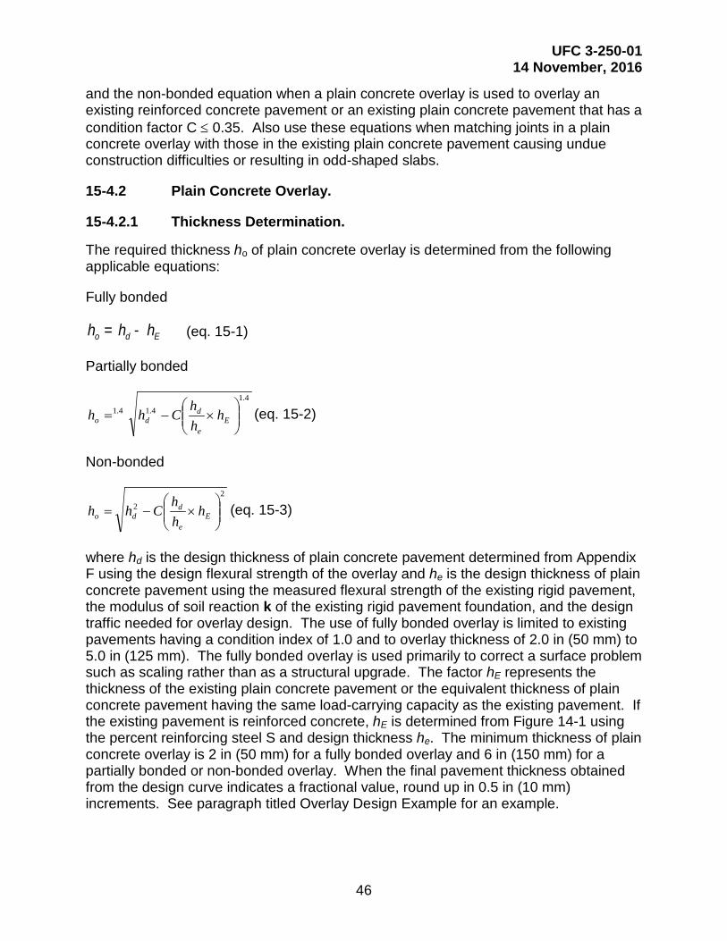
UFC 3-250-01 14 November, 2016
46
and the non-bonded equation when a plain concrete overlay is used to overlay an existing reinforced concrete pavement or an existing plain concrete pavement that has a condition factor C ≤ 0.35. Also use these equations when matching joints in a plain concrete overlay with those in the existing plain concrete pavement causing undue construction difficulties or resulting in odd-shaped slabs.
15-4.2 Plain Concrete Overlay.
15-4.2.1 Thickness Determination.
The required thickness ho of plain concrete overlay is determined from the following applicable equations:
Fully bonded
= -o d Eh h h (eq. 15-1)
Partially bonded
4.14.14.1
×−= E
e
ddo h
hh
Chh (eq. 15-2)
Non-bonded
22
×−= E
e
ddo h
hh
Chh (eq. 15-3)
where hd is the design thickness of plain concrete pavement determined from Appendix F using the design flexural strength of the overlay and he is the design thickness of plain concrete pavement using the measured flexural strength of the existing rigid pavement, the modulus of soil reaction k of the existing rigid pavement foundation, and the design traffic needed for overlay design. The use of fully bonded overlay is limited to existing pavements having a condition index of 1.0 and to overlay thickness of 2.0 in (50 mm) to 5.0 in (125 mm). The fully bonded overlay is used primarily to correct a surface problem such as scaling rather than as a structural upgrade. The factor hE represents the thickness of the existing plain concrete pavement or the equivalent thickness of plain concrete pavement having the same load-carrying capacity as the existing pavement. If the existing pavement is reinforced concrete, hE is determined from Figure 14-1 using the percent reinforcing steel S and design thickness he. The minimum thickness of plain concrete overlay is 2 in (50 mm) for a fully bonded overlay and 6 in (150 mm) for a partially bonded or non-bonded overlay. When the final pavement thickness obtained from the design curve indicates a fractional value, round up in 0.5 in (10 mm) increments. See paragraph titled Overlay Design Example for an example.
UFC 3-250-01 14 November, 2016
47
15-4.2.2 Jointing.
For all partially bonded and fully bonded plain concrete overlays, provide joints in the overlay to coincide with all joints in the existing rigid pavement. It is not necessary for joints in the overlay to be of the same type as joints in the existing pavement. When it is impractical to match the joints in the overlay to joints in the existing rigid pavement, either use a bond-breaking medium and design the overlay as a non-bonded overlay or reinforce the overlay over the mismatched joints. Should the mismatch of joints become severe, consider a reinforced concrete overlay design as an economic alternative to the use of a non-bonded plain concrete overlay. For non-bonded plain concrete overlays, the design and spacing of transverse contraction joints is in accordance with requirements for plain concrete pavements. For both partially bonded and non-bonded plain concrete overlays, dowel the longitudinal construction joints using the dowel size and spacing discussed in Chapter titled Rigid Overlay Of Existing Flexible Or Composite Pavements. Do not use dowels and load-transfer devices in fully bonded overlays. Joint sealing for plain concrete overlays must conform to the requirements for plain concrete pavements.
15-4.3 Reinforced Concrete Overlay.
A reinforced concrete overlay may be used to strengthen either, an existing plain concrete pavement, or an existing reinforced concrete pavement. Generally, the overlay will be designed as a partially bonded overlay. Use the non-bonded overlay design only when a leveling course is required over the existing pavement. Design the reinforcement steel for reinforced concrete overlays and place in accordance with reinforced concrete pavements.
15-4.3.1 Thickness Determination.
Determine the required thickness of reinforced concrete overlay using Figure 14-1 after determining the thickness of plain concrete overlay from the appropriate overlay equation. Then, using the value for the thickness of plain concrete overlay, select either the thickness of reinforced concrete overlay and determine the required percent steel or select the percent steel and determine the thickness of reinforced concrete overlay from Figure 14-1. The minimum thickness of reinforced concrete overlay must be 6 in (150 mm).
15-4.3.2 Jointing.
Whenever possible, the longitudinal construction joints in the overlay should match the longitudinal joints in the existing pavement. Dowel all longitudinal joints dowel size and spacing designated in Chapter titled Joints For Plain Concrete using the thickness of reinforced concrete overlay. It is not necessary for transverse joints in the overlay to match joints in the existing pavement; however, when practical, match the joints. Determine the maximum spacing of transverse contraction joints in accordance with equation 17-1, but do not exceed 75 ft (25 m) regardless of the thickness of the pavement or the percent steel used. Joint sealing for reinforced concrete pavements must conform to the requirements for plain concrete pavements.
UFC 3-250-01 14 November, 2016
48
15-5 RIGID OVERLAY OF EXISTING FLEXIBLE OR COMPOSITE PAVEMENTS.
15-5.1 Flexible Pavements.
Design a rigid overlay of an existing flexible pavement in the same way as a rigid pavement on grade. Determine a modulus of subgrade reaction k by a plate-bearing test performed on the surface of the existing flexible pavement. If it is not practical to determine k from a plate-bearing test, use Figure 10-1 to determine an approximate value. Figure 10-1 yields an effective k value at the surface of the flexible pavement as a function of the subgrade k and thickness of base and subbase above the subgrade. When using Figure 10-1, consider the bituminous concrete to be unbound base course material. Using this k value and the concrete flexural strength, determine the required thickness of plain concrete overlay from the charts in Appendix F. However, the following limitations should apply:
• In no case should a k value greater than 500 pci (140 KPa/mm) be used.
• Perform the plate-bearing test to determine the k value on the flexible pavement at a time when the temperature of the bituminous concrete is within five degrees of the ambient temperature of the hottest period of the year in the locality of the proposed construction.
15-5.2 Composite Base Pavements.
Two conditions of composite pavement are possible when considering a rigid overlay. When the composite pavement is composed of a rigid base pavement with less than 4 in (100 mm) of all-bituminous overlay, determine the required thickness of rigid overlay using the non-bonded overlay equation. If the composite pavement is composed of a rigid base pavement with 4 in (100 mm) or more of either all bituminous or bituminous with base course overlay, determine the required thickness of overlay by paragraph titled Flexible Pavements above. The same limitations for maximum k value and temperature of pavement during testing apply.
15-6 FLEXIBLE OVERLAY OF FLEXIBLE PAVEMENT.
Overlays are used for strengthening or rehabilitation of an existing pavement. Strengthening is required when heavier loads are introduced or when a pavement is no longer capable of supporting the loads for which it was designed. Rehabilitation may include sealing or resealing of cracks, patching, limited reconstruction before an overlay, restoration of the surface profile, improvement of skid resistance by a friction course, or improvement of the surface quality. When it has been determined that strengthening is required, design the overlay by designing a new pavement and comparing its thickness with the thickness of the existing pavement. The difference between these two pavements is the thickness of overlay required to satisfy design requirements. Overlays may be all-bituminous concrete or asphalt concrete and base course. The flexible pavement, after being overlaid, must meet all compaction requirements of a new pavement. Where the existing construction is complex, consisting of several layers, and especially where there are semi-rigid layers, such as soil cement, cement-stabilized soils, or badly cracked PCC, exercise careful judgment
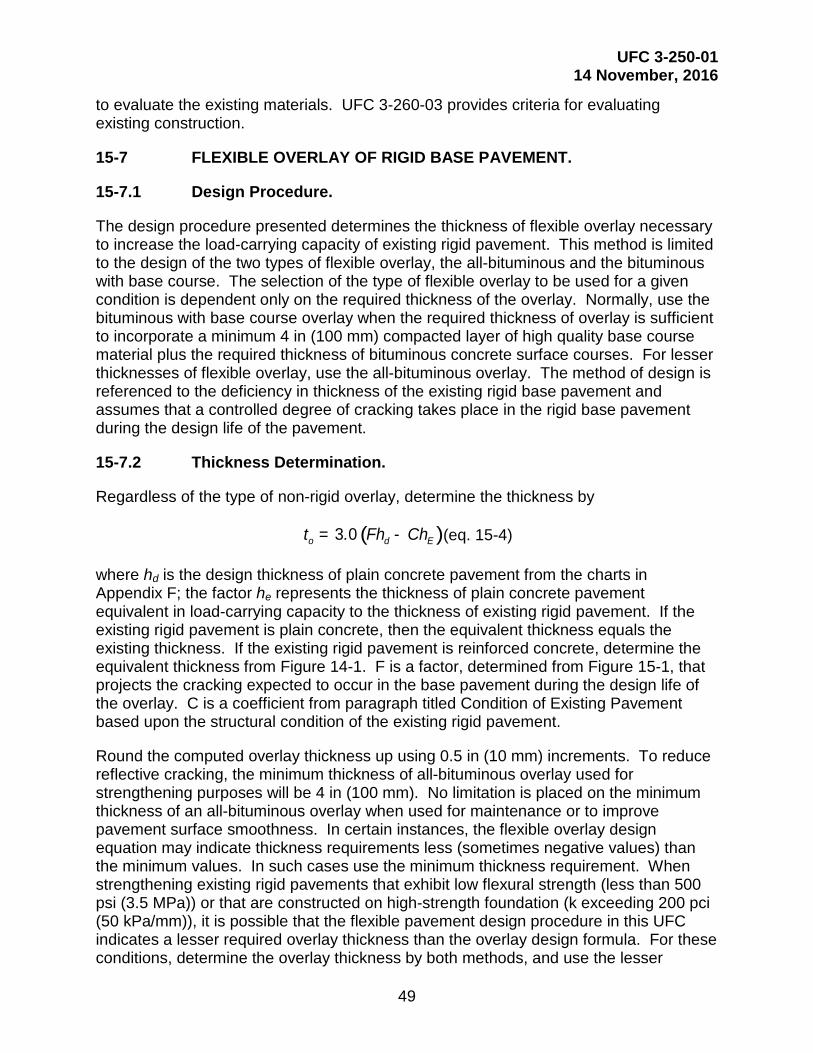
UFC 3-250-01 14 November, 2016
49
to evaluate the existing materials. UFC 3-260-03 provides criteria for evaluating existing construction.
15-7 FLEXIBLE OVERLAY OF RIGID BASE PAVEMENT.
15-7.1 Design Procedure.
The design procedure presented determines the thickness of flexible overlay necessary to increase the load-carrying capacity of existing rigid pavement. This method is limited to the design of the two types of flexible overlay, the all-bituminous and the bituminous with base course. The selection of the type of flexible overlay to be used for a given condition is dependent only on the required thickness of the overlay. Normally, use the bituminous with base course overlay when the required thickness of overlay is sufficient to incorporate a minimum 4 in (100 mm) compacted layer of high quality base course material plus the required thickness of bituminous concrete surface courses. For lesser thicknesses of flexible overlay, use the all-bituminous overlay. The method of design is referenced to the deficiency in thickness of the existing rigid base pavement and assumes that a controlled degree of cracking takes place in the rigid base pavement during the design life of the pavement.
15-7.2 Thickness Determination.
Regardless of the type of non-rigid overlay, determine the thickness by
( )= -3 0o d Et . Fh Ch (eq. 15-4)
where hd is the design thickness of plain concrete pavement from the charts in Appendix F; the factor he represents the thickness of plain concrete pavement equivalent in load-carrying capacity to the thickness of existing rigid pavement. If the existing rigid pavement is plain concrete, then the equivalent thickness equals the existing thickness. If the existing rigid pavement is reinforced concrete, determine the equivalent thickness from Figure 14-1. F is a factor, determined from Figure 15-1, that projects the cracking expected to occur in the base pavement during the design life of the overlay. C is a coefficient from paragraph titled Condition of Existing Pavement based upon the structural condition of the existing rigid pavement.
Round the computed overlay thickness up using 0.5 in (10 mm) increments. To reduce reflective cracking, the minimum thickness of all-bituminous overlay used for strengthening purposes will be 4 in (100 mm). No limitation is placed on the minimum thickness of an all-bituminous overlay when used for maintenance or to improve pavement surface smoothness. In certain instances, the flexible overlay design equation may indicate thickness requirements less (sometimes negative values) than the minimum values. In such cases use the minimum thickness requirement. When strengthening existing rigid pavements that exhibit low flexural strength (less than 500 psi (3.5 MPa)) or that are constructed on high-strength foundation (k exceeding 200 pci (50 kPa/mm)), it is possible that the flexible pavement design procedure in this UFC indicates a lesser required overlay thickness than the overlay design formula. For these conditions, determine the overlay thickness by both methods, and use the lesser

UFC 3-250-01 14 November, 2016
50
thickness for design. For the flexible pavement design procedure, consider the existing rigid pavement an equivalent thickness of high quality crushed aggregate base (CBR = 100), and determine the total pavement thickness based upon the subgrade CBR. Consider any existing base or subbase layers as corresponding layers in the flexible pavement. The thickness of required overlay is then the difference between the required flexible pavement thickness and the combined thicknesses of existing rigid pavement and any base or subbase layers above the subgrade.
Figure 15-1 Factor for Projecting Cracking in a Flexible Pavement

UFC 3-250-01 14 November, 2016
51
15-7.3 Jointing.
Normally, joints, other than those required for construction of a bituminous concrete pavement, are not required in flexible overlays of existing rigid pavements. It is good practice to try to layout paving lanes in the bituminous concrete to prevent joints in the overlay from coinciding with joints in the rigid base pavement. Movements of the existing rigid pavement, both from contraction and expansion and deflections due to applied loads, cause high concentrated stresses in the flexible overlay directly over joints and cracks in the existing rigid pavements. These stresses may result in cracking, often referred to as reflection cracks, in the overlay. The severity of this type of cracking depends, in part, upon the type of rigid pavement. For example, a plain concrete pavement normally has closely spaced joints and may result in reflection cracks over the joints, but the cracks are fairly tight and less likely to ravel. Nevertheless, reinforced concrete pavements normally have joints spaced farther apart, which in turn experience larger movements. The reflection cracks over these joints are more likely to ravel and spall. Likewise, either existing plain concrete or reinforced concrete pavements may have expansion joints that experience rather large movements, and consideration should be given to provide an expansion joint in the flexible overlay to coincide with the expansion joint in the existing pavement. No practical method has been developed to absolutely prevent reflective cracking in flexible overlays; however, experience shows that the degree of cracking is related to the thickness of the overlay, with the thinner overlays exhibiting the greater tendency to crack.
15-8 USE OF GEOTEXTILES TO RETARD REFLECTIVE CRACKING.
Geotextiles are effective in retarding reflective cracking in some areas of the United States, as shown in Figure 15-2. When using geotextiles under an asphalt concrete pavement, the existing pavement should be relatively smooth with all cracks larger than 0.25 in (6 mm) sealed. A leveling course is also recommended before application of the fabric to ensure a suitable surface. A tack coat is also required immediately before placement of the geotextile. The minimum overlay thickness is shown in Figure 15-2. When using geotextiles under a flexible pavement overlay, the geotextiles can be used as a membrane strip or a full-width application. The existing pavement should be stable with negligible movement under loads and all joints and cracks larger than 0.25 in (6 mm) sealed. With the strip method, apply the geotextile directly on the concrete joints and cracks and then overlay. With the full-width method, apply the geotextile directly to the existing pavement or place on a leveling course. In flexible overlays, the lower viscosity (or higher penetration grade) asphalts are less likely to experience reflective cracking. Therefore, use the lowest viscosity grade asphalt that provides sufficient stability during high temperatures.

UFC 3-250-01 14 November, 2016
52
Figure 15-2 Location Guide for the Use of Geotextiles in Retarding Reflective Cracking
15-9 OVERLAYS IN FROST REGIONS.
Whenever the subgrade is susceptible to differential heaving or weakening during the frost-melt period, the overlay design should meet the requirements for frost action as given in Chapter titled Seasonal Frost Conditions. When it is determined that distress in an existing pavement has been caused by differential heaving due to frost action, an overlay may not correct the condition unless the combined thickness of the pavement is sufficient to prevent substantial frost penetration into the underlying frost-susceptible material.
15-10 OVERLAY DESIGN EXAMPLE.
Appendix G includes examples of design for bonded, partially bonded, unbounded rigid overly and flexible overlay design.
AREA I – GEOTEXTILES ARE RECOMMENDED WITH MINIMUM OVERLAY THICKNESS OF 2 IN. AREA II – ARE RECOMMENDED WITH OVERLAY THICKNESS OF 3-4 IN. AREA III – GEOTEXTILES ARE NOT RECOMMENDED

UFC 3-250-01 14 November, 2016
53
CHAPTER 16 JOINTS FOR PLAIN CONCRETE
16-1 ROADWAYS
A typical layout and cross section of a roadway is presented in Figure C16-1 (Appendix C) and shows the location of various types of joints. Figure C16-2, Figure C16-3, Figure C16-4, Figure C16-5, and Figure C16-6 (Appendix C) show the associated details for the design and construction of plain concrete pavements. Figure C14-1 (Appendix C) presents a layout of joints at intersections of plain concrete pavements. Figure C16-2 (Appendix C) shows the layout of joints for plain concrete parking areas. Joints for roller compacted concrete pavements (RCCP) are discussed in Chapter 18.
16-2 JOINT TYPES AND USAGE.
Joints are provided to permit contraction and expansion of the concrete resulting from temperature and moisture changes, to relieve warping and curling stresses due to temperature and moisture differentials, to prevent unsightly irregular breaking of the pavement, and as a construction expedient, to separate sections or strips of concrete placed at different times. The three general types of joints are contraction, construction, and expansion and are shown in Figure C16-7 (Appendix C).
16-2.1 Contraction Joints.
Weakened-plane contraction joints control cracking in the concrete and limit curling or warping stresses resulting from drying shrinkage and contraction, and from temperature and moisture gradients in the pavement, respectively. Shrinkage and contraction of the concrete causes slight cracking and separation of the pavement at the weakened planes, which provides some relief from tensile forces resulting from foundation restraint and compressive forces caused by subsequent expansion. Contraction joints are required transversely and may be required longitudinally depending upon pavement thickness and spacing of construction joints. UFC 3-250-04 contains instructions for the use of sawcuts or preformed inserts to form the weakened plane.
16-2.1.1 Width and Depth of Weakened Plane Groove.
The width of the weakened plane groove must be a minimum of 1/8 in (3 mm) and a maximum equal to the width of the sealant reservoir. The depth of the weakened plane groove must be great enough to cause the concrete to crack under the tensile stresses resulting from the shrinkage and contraction of the concrete as it cures. Experience, supported by analyses, indicates that this depth should be at least one-fourth of the slab thickness for pavements 12 in (300 mm) or less, and 3 in (75 mm) for pavements greater than 12 in (300 mm) and less than 18 in (450 mm) in thickness. In no case is the depth of the groove less than the maximum nominal size of aggregate used. Concrete placement conditions may influence the fracturing of the concrete and dictate the depth of groove required. For example, concrete placed early in the day, when the air temperature is rising, may experience expansion rather than contraction during the early life of the concrete with subsequent contraction occurring several hours later as the air temperature drops. The concrete may have attained sufficient strength before the contraction occurs so that each successive weakened plane does not result in

UFC 3-250-01 14 November, 2016
54
fracturing of the concrete. As a result, an excessive opening may result where fracturing does occur. To prevent such an opening, increase the depth of the groove to one-third of the slab thickness to assure the fracturing and proper functioning of each of the scheduled joints.
16-2.1.2 Width and Depth of Sealant Reservoir.
The dimensions of the sealant reservoir are critical to satisfactory performance of the joint sealing materials. The minimum width is 3/4-in (19 mm) and the minimum depth is 1.0 – 1.5 times the width.
16-2.1.3 Spacing of Transverse Contraction Joints.
Transverse contraction joints must be constructed across each paving lane perpendicular to the center line. The spacing between transvers contraction joints is generally 10 ft (3 m). If possible the slabs should be close to square or the joint spacing should equal the paving width. In regions where the design freezing index is 1,800 or more degree days the maximum spacing should be 20 ft (6 m). The joint spacing must be uniform throughout any major paved area, and each joint must be straight and continuous from edge to edge of the paving lane and across all paving lanes for the full width of the paved area. Staggering of joints in adjacent paving lanes can lead to sympathetic cracking and is not permitted unless reinforcement is used or separated by a thickened edge expansion joint. The maximum spacing of transverse joints that effectively control cracking varies appreciably depending on pavement thickness, thermal coefficient and other characteristics of the aggregate and concrete, climatic conditions, and foundation restraint. It is impractical to establish limits on joint spacing that are suitable for all conditions without making them unduly restrictive. The joint spacing in Table 16-1 give satisfactory control of transverse cracking in most instances, subject to modification based on available information regarding the performance of existing pavements in the vicinity or unusual properties of the concrete. Experience shows that oblong slabs, especially in thin pavements, tend to crack into smaller slabs of nearly equal dimensions under traffic. Therefore, it is desirable, insofar as practicable, to keep the length and width dimensions as nearly equal as possible. In no case should the length dimension (in the direction of paving) exceed the width dimension more than 25 percent. Use joint spacing as indicated in Table 16-1 or as approved by the Government Civil Engineer. Requests must indicate local conditions and justification for the proposed change in joint spacing.
Table 16-1 Allowable Spacing of Longitudinal and Transverse Contraction Joints
Pavement Thickness, in (mm) Spacing of Joint, ft (m)
Less than 9 (225) 10 to 15 (3.0 to 4.6)
9 to 12 (225 to 300) 15 to 20 (4.6 to 6.1) Over 12 (300) 20 (6.1)* * The maximum spacing of transverse contraction joints for DoD pavements is 20 ft (6.1 m).

UFC 3-250-01 14 November, 2016
55
16-2.1.4 Spacing of Longitudinal Contraction Joints.
Contraction joints must be placed along the centerline of paving lanes that have a width greater than the determined maximum spacing of transverse contraction joints in Table 16-1. These joints may also be required in the longitudinal direction for overlays, regardless of overlay thickness, to match joints existing in the base pavement unless a bond-breaking medium is used between the overlay and base pavement or the overlay pavement is reinforced. Normally, the contractor should be given the option to used construction joints in the longitudinal paving direction to permit smaller paving equipment to be used.
16-2.1.5 Doweled and Tied Contraction Joints.
16-2.1.5.1 Transverse Joints.
Dowels are required in transverse contraction joints for plain concrete pavements for roads and parking areas that use slab lengths greater than those in Table 16-1. Dowels are recommended in the last joint at ends of long paving lanes such as large storage and parking areas. Doweled transverse contraction joints in plain concrete pavement are required to ensure joint load transfer under heavy, repeated loads and reduce slab pumping and faulting. Doweled transverse contraction joints provide a smoother driving surface across the joint. Doweled transverse contraction joints in reinforced concrete pavements are required to ensure good joint transfer where conventional contraction joints may have inadequate load transfer because of excessive joint opening. Table 16-2 presents the size and spacing of dowels. Because of inadequate thermal expansion and contraction capability, not more than two consecutive joints must be constructed with tied bars. Smooth dowel must be used in every other joint.
Table 16-2 Dowel Size and Spacing for Construction, Contraction, and Expansion Joints
Pavement Thickness, in (mm)
Minimum Dowel Length, in (mm)
Max Dowel Spacing, in (mm)
Dowel Diameter and Type
Less than 8 (200) 16 (400) 12 (300) .75 in (20 mm) bar
8 to 11 (200 to 275) 16 (400) 12 (300) 1 in (25 mm) bar
12 to 15 (300 to 380) 20 (510) 15 (375) 1 in (25 mm) to 1.25 in (32 mm) bar, or 1 in (25 mm) extra strength pipe*
* Extra strength pipe will be filled or plugged when used.
16-2.1.5.2 Longitudinal Joints
For plain concrete pavements, deformed tie bars are required in longitudinal contraction joints that fall 15 ft (4.6 m) or less from the free edge of paved areas that are 100 ft (30.5 m) or greater in width. The deformed tie bars must be 30 in (750 mm) long, and spaced on 30 in (750 mm) centers. In addition, longitudinal contraction joints placed along the center line of paving lanes that have a width greater than the maximum

UFC 3-250-01 14 November, 2016
56
spacing of transverse contraction joints must be tied using tie bars of the dimensions shown in Figure C16-3 (Appendix C).
16-2.2 Construction Joints.
Construction joints may be required in both the longitudinal and transverse directions. Longitudinal construction joints, generally spaced 10 to 25 ft (3.0 to 7.6 m) apart but which may reach 50 ft (15.2 m) apart, depending on construction equipment capability, must be provided to separate successively placed paving lanes. Transverse construction joints must be installed at the end of each day's paving operation and at other points within a paving lane where the placing of concrete is discontinued a sufficient length of time for the concrete to start to set. All transverse construction joints should be located in place of other regularly spaced transverse joints (contraction or expansion types). There are several types of construction joints available for use, as described below. The selection of the type of construction joint depends on such factors as the concrete placement procedure (formed or slip formed) and foundation conditions. Make longitudinal changes in grade at a joint if slip formed paving is permitted. Spacing between longitudinal joints in parking areas should be as uniform as possible to minimize contractor downtime required to adjust paver width.
16-2.2.1 Doweled Joint.
The doweled joint is the best joint for providing load transfer and maintaining slab alignment. It is a desirable joint for the most adverse conditions such as heavy loading, high traffic intensity, and lower strength foundations. However, because the alignment and placement of the dowel bars are critical to satisfactory performance, this type of joint is difficult to construct, especially for slip formed concrete. However, the doweled joint is required for all transverse construction joints in plain concrete pavements.
16-2.2.2 Thickened-Edge Joint.
Thickened-edge type joints may be used instead of other types of joints using load transfer devices. When the thickened-edge joint is constructed, the thickness of the concrete at the edge is increased to 125 percent of the design thickness. The thickness is then reduced by tapering from the free-edge thickness to the design thickness at a distance of 5 ft (1.5 m) from the longitudinal edge. For pavement thickness less than 12 in (300 mm), the taper distance can be reduced to 3 ft (0.9 m) at the designer’s option. The thickened-edge joint is considered adequate for the load-induced concrete stresses. However, the inclusion of a key in the thickened-edge joint Figure C16-4 (Appendix C) provides some degree of load transfer in the joint and helps to maintain slab alignment; although not required, it can be used for pavement constructed on low- to medium-strength foundations. The thickened-edge joint may be used at free edges of paved areas to accommodate future expansion of the facility or where wheel loadings may track the edge of the pavement. The use of this type joint is contingent upon adequate base course drainage meeting requirements of UFC 3-250-04.

UFC 3-250-01 14 November, 2016
57
16-2.2.3 Keyed Joint.
The keyed joint is the most economical method, from a construction standpoint, for providing load transfer in the joint. The key or keyway can be satisfactorily constructed using either formed or slip formed methods. The required dimensions of the joint can best be maintained by forming or slip forming the keyway rather than the key. The dimensions and location of the key are critical to its performance. Deviations exceeding the stated tolerances can result in failure in the joint. Keyed joints should not be used in rigid pavements that are less than 9 in (225 mm) in thickness. Tie bars in the keyed joint limit opening of the joint and provide some shear transfer that will improve the performance of the keyed joints. However, tying all joints in pavement widths of more than 75 ft (25 m) can result in excessive stresses and cracking in the concrete during contraction.
16-2.3 Expansion Joints.
Expansion joints must be used at all intersections of pavements with structures or with other concrete pavements where paving lanes are perpendicular to each other, and they may be required within the pavement features. The types of expansion joints are the thickened-edge joint, the thickened-edge slip joint, and the doweled type joint. Refer to Figure C16-5 and Figure C16-6 (Appendix C). Filler material for the thickened-edge and doweled type expansion joint must be a non-extruding type. The type and thickness of filler material and the way of its installation will depend upon the particular case. Usually, a preformed material of 3/4-in (19 mm) thickness is adequate; however, in some instances, a greater thickness of filler material may be required. Filler material for slip joints must be either a heavy coating of bituminous material not less than 1/16 in (1.5 mm) in thickness when joints match or a normal non-extruding-type material not less than 1/4 in (6 mm) in thickness when joints do not match. Where large expansions may have a detrimental effect on adjoining structures, such as at the juncture of rigid and flexible pavements, consider expansion joints in successive transverse joints back from the juncture. The depth, length, and position of each expansion joint must be sufficient to form a complete and uniform separation between the pavements or between the pavement and the structure concerned.
16-2.3.1 Between Pavement and Structures.
Expansion joints must be installed to surround, or to separate from the pavement, any structures that project through, into, or against the pavements, such as at the approaches to buildings or around drainage inlets. The thickened edge expansion joint is generally best suited for these places. Refer to Figure C16-5 (Appendix C).
16-2.3.2 Within Pavements and at Pavement Intersections.
Expansion joints within pavements are difficult to construct and maintain and often contribute to pavement failures. Keep their use to the absolute minimum necessary to prevent excessive stresses in the pavement from expansion of the concrete or to avoid distortion of a pavement through the expansion of an adjoining pavement. Determine the need for and spacing of expansion joints based upon pavement thickness, thermal properties of the concrete, prevailing temperatures in the area, temperatures during the

UFC 3-250-01 14 November, 2016
58
construction period, and the experience with concrete pavements in the area. Unless needed to protect abutting structures, omit expansion joints in all pavements 10 in (250 mm) or more in thickness and also in pavements less than 10 in (250mm) thickness when the concrete is placed during warm weather since the initial volume of the concrete on hardening will be at or near the maximum. However, for concrete placed during cold weather, expansion joints may be used in pavements less than 10 in (250 mm) thick.
16-2.3.2.1 Longitudinal Joints
Longitudinal expansion joints within pavements must be of the thickened-edge type, refer to Figure C16-5 (Appendix C). Dowels are not permitted in longitudinal expansion joints because differential expansion and contraction parallel with the joints may develop undesirable localized strains and cause failure of the concrete, especially near the corners of slabs at transverse joints. Expansion joints are not required between two adjoining pavements where paving lanes of the two pavements are parallel.
16-2.3.2.2 Transverse Joints
Transverse expansion joints in roads are typically not needed since the initial volume of concrete hardening will be at or near the maximum. Transverse expansion joints in roads and parking areas can progressively close up over the years, allowing adjacent contraction joints to open more. The result is increased infiltration of fines and loss of load transfer in the adjacent contraction joints. Transverse expansion joints are required at bridge approach slabs. Thickened edge expansion joints may be used in roads and parking areas which do not require doweled contraction joints. Transverse expansion joints may be considered when pavement is constructed at low temperature or using materials that in the past have shown high expansion characteristics.
16-2.3.2.3 Slip Joints
A special expansion joint, the slip joint, is required at pavement intersections.
16-3 DOWELS.
The important functions of dowels or any other load-transfer device in concrete pavements are to help maintain the alignment of adjoining slabs and to transfer some stresses from loads to the adjacent slab, thereby limiting or reducing stresses in the loaded slab. Specify different sizes of dowels for different thicknesses of pavements as indicated in Table 16-2. When extra strength pipe is used for dowels, fill the pipe with either a stiff mixture of sand-asphalt or Portland cement mortar or plug the ends of the pipe. If the ends of the pipe are plugged, the plug must fit inside the pipe and be cut off flush with the end of the pipe so that there will be no protruding material to bond with the concrete and prevent free movement of the dowel. All dowels must be straight, smooth, and free from burrs at the ends. One end of the dowel will be painted and oiled to prevent bonding with the concrete. Dowels used at expansion joints must be capped at one end, in addition to being painted and oiled, to permit further penetration of the dowels into the concrete when the joints close.
UFC 3-250-01 14 November, 2016
59
16-4 SPECIAL PROVISIONS FOR SLIP FORM PAVING.
Make provisions for slip form pavers when there is a change in longitudinal joint configuration. The thickness may be varied without stopping the paving train, but the joint configuration cannot be varied without changing the side forms, which normally require stopping the paver and installing a header. The following requirements apply at a pavement transition area.
16-4.1 Header.
The header may be set on either side of the transition slab with the transverse construction joint doweled, as required. The dowel size and location in the transverse construction joint should be commensurate with the thickness of the pavement at the header.
16-4.2 Transition Between Different Joints.
When there is a transition between a doweled longitudinal construction joint and a keyed longitudinal construction joint, the longitudinal construction joint in the transition slab may be either keyed or doweled. The size and location of the dowels or keys in the transition slabs should be the same as those in the pavement with the doweled or keyed joint, respectively.
16-4.3 Transition Between Two Keyed Joints.
When there is a transition between two keyed joints with different dimensions, the size and location of the key in the transition slab should be based on the thickness of the thinner pavement.
16-5 JOINT SEALING.
All joints will be sealed to prevent infiltration of surface water and solid substances. Use a jet fuel resistant sealant, either poured or preformed, in the joints of hardstands, wash racks, and other paved areas where fuel or other lubricants may be spilled during the operation, parking, maintenance, and servicing of vehicles. Poured joint sealant must conform to UFGS 32 01 19 and preformed joint seals must conform to UFGS 32 13 73. Use sealants that are not fuel resistant in joints of all other pavements. Compress preformed sealants 45 to 85 percent of their original width. Base the selection of poured or preformed sealant upon economics. Compression-type preformed sealants are recommended when the joint spacing exceeds 25 ft (7.6 m). For many projects the cold applied (silicone) sealants have the best life-cycle cost.
16-6 SPECIAL JOINTS AND JUNCTURES.
Situations can develop where special joints or variations of the more standard type joints are needed to accommodate the movements that occur and to provide a satisfactory operational surface. Some of these special joints or junctures are as follows:

UFC 3-250-01 14 November, 2016
60
16-6.1 Slip-Type Joints.
At the juncture of two pavement facilities, expansion and contraction of the concrete may result in movements that occur in different directions. Such movements may create detrimental stresses within the concrete unless provision is made to allow the movements to occur. At such junctures, a thickened-edge slip joint must be used to permit the horizontal slippage to occur. The design of the thickened-edge slip joint is similar to the thickened-edge construction joint. Refer to Figure C16-6 (Appendix C). The bond-breaking medium must be either a heavy coating of bituminous material not less than 1/16 in (1.5 mm) in thickness when joints match or a normal non-extruding type expansion joint material not less than 1/4 in (6 mm) in thickness when joints do not match. The 1/16 in (1.5 mm) bituminous coating may be either a low penetration (60 to 70 grade asphalt) or a clay-type asphalt-base emulsion similar to that used for roof coating and must be applied to the face of the joint by hand brushing or spraying.
16-6.2 Joints Between New and Existing Pavements.
A special thickened-edge joint design, refer to Figure C16-4 (Appendix C), must be used at the juncture of new and existing pavements for the following conditions:
• When load-transfer devices (keyways or dowels) or a thickened edge are not provided at the free edge of the existing pavement.
• When load-transfer devices or a thickened edge is provided at the free edge of the existing pavement, but neither meet the design requirements for the new pavement.
• For transverse contraction joints, when removing and replacing slabs in an existing pavement.
• For longitudinal construction joints, when removing and replacing slabs in an existing pavement if the existing load-transfer devices are damaged during the pavement removal.
• Any other location where it is necessary to provide load transfer for the existing pavements. The special joint design may not be required if a new pavement joins an existing pavement that is grossly inadequate to carry the design load of the new pavement or if the existing pavement is in poor structural condition. If the existing pavement can carry a load that is 75 percent or less of the new pavement design load, special efforts to provide edge support for the existing pavement may be omitted and the alternate thickened-edge joint used as shown in Figure C16-4 (Appendix C); however, if omitted, the existing pavement may experience accelerated failures. Design the new pavement with a thickened edge at the juncture. Use any load-transfer devices in the existing pavement at the juncture to provide as much support as possible to the existing pavement. Consider drilling and grouting dowels in the existing pavement for edge support as an alternate to the special joint; however, use a thickened-edge design for the new pavement at the juncture.
UFC 3-250-01 14 November, 2016
61
CHAPTER 17 JOINTS FOR REINFORCED CONCRETE
17-1 REQUIREMENTS.
The exceptions for joint requirements and types of reinforced concrete pavements are the same as for plain concrete pavements except as listed below.
Figure C17-1, Figure C17-2 and Figure C17-3 (Appendix C) show the associated details for the design and construction of joints for reinforced concrete pavements.
17-1.1 Unscheduled Joints.
All joints falling at a point other than a regularly scheduled transverse contraction joint must be doweled with the exception of the thickened-edge type. One end of the dowel must be painted and oiled to permit movement at the joint.
17-1.2 Thickened-Edge-Type Joints.
Thickened-edge-type joints must not be doweled. Thicken the edge to 125 percent of the design thickness.
17-1.3 Transverse Construction Joint.
When a transverse construction joint is required within a reinforced concrete slab unit not at a regularly scheduled contraction joint location, carry the reinforcing steel through the joint. In addition, use dowels meeting the size and spacing requirements of Table 16-2 for the design thickness in the joint.
17-1.4 Transverse Contraction Joints.
Transverse contraction joints in reinforced concrete pavements should be constructed across each paving lane, perpendicular to the pavement center line, and at intervals of not less than 25 ft (7.6 m) nor more than 75 ft (25 m). The maximum allowable slab width or length for reinforced concrete pavements is a function of the effective frictional restraint developed at the interface between the slab and subgrade, the percentage of steel reinforcing used in the slab, and the yield strength of the steel reinforcing. Allowable slab widths or lengths can be determined directly from Figure 14-1 for yield strengths of 60,000 psi (410 MPa). If it is desired to use reinforcing steel having a yield strength other than this value, determine the maximum allowable slab width or length from the following equation:

UFC 3-250-01 14 November, 2016
62
Equation 17-1 ( )[ ]31200047.0 SfhL sr ⋅⋅⋅=
where
hr=thickness of reinforced concrete pavement, in
fs= yield strength of reinforcing steel, psi
S=percent of reinforcing steel
17-1.5 Two Traffic Lanes.
For reinforced concrete pavements where two traffic lanes are placed as a single paving lane, provide a longitudinal contraction joint at the center line of the paving lane to control cracking. In these joints, carry the reinforcing steel through the joint. Tie bars are not required.
17-1.6 Pavement Center Line.
Tied longitudinal contraction joints are also required at the center line of reinforced concrete pavements when the width of the pavement exceeds the allowable length of slab L for the percentage of steel reinforcement being used. When such joints are required, break the steel reinforcement at the joint, and use 5/8-in (16-mm) diameter tie bars 30 in (750 mm) long and spaced 30 in (750 mm) center to center.
17-2 JOINT SEALING.
Joint sealing for reinforced concrete pavements must be the same as for plain concrete pavements (see paragraph 15-5). Use preformed compression sealants when the joint spacing exceeds 50 ft (15.2 m).

UFC 3-250-01 14 November, 2016
63
CHAPTER 18 ROLLER-COMPACTED CONCRETE PAVEMENTS
18-1 INTRODUCTION.
RCCP is a zero-slump PCC mixture that is placed with an asphalt concrete paving machine and compacted with vibratory and rubber-tired rollers. Mixture proportions and most engineering properties of RCCP are similar to those of conventional plain concrete pavements. The mixture proportions of RCCP are not appreciably different than those used in conventional concrete; flexural strengths of beams taken from RCCP facilities and test sections routinely exceed 650 psi (4.5 MPa) at 28 days. Limited tests show that the fatigue characteristics of RCCP mixtures are similar to those of conventional concrete pavement mixtures. In Canada under moderately severe environmental and heavy loading conditions, RCCP hardstands have performed well for over 10 years alongside conventional concrete hardstands. Therefore, it may be assumed that the same rationale applied to the thickness design for plain non-reinforced concrete pavement thickness may also be applied to the design of RCCP.
18-2 LOAD TRANSFER.
A major difference exists in the assumptions of load transfer at joints made for plain concrete pavements and RCCP, which directly affects the design stress and therefore the thickness of the pavement. RCCP has typically been allowed to crack naturally, and spacing between these cracks is usually irregular, ranging from 40 to 70 ft (12 to 21 m) apart. Although, spacing between cracks have been reported much greater than and lower than this range. Consequently, the width of the crack opening will be greater and the load transfer developed from aggregate interlock at the cracks will be highly variable, if not totally lost. Limited tests at Fort Hood, TX and Fort Stewart, GA have revealed average load transfer at transverse contraction cracks of 18.6 percent (standard deviation of 6.7 percent) and longitudinal cracks of 16.7 percent (standard deviation of 5.9 percent), respectively. Tests on longitudinal and transverse cold (construction) joints revealed even less load transfer. Therefore, the assumption of 25 percent load transfer at joints constructed of plain concrete would not be valid for RCCP thickness design. Therefore, base the thickness design of RCCP on no load transfer at the joints, (i.e. assuming all joints and cracks to be a free edge condition).
18-3 THICKNESS DESIGN.
Use the thickness design curves shown in Appendix F to determine thickness requirements for RCCP. These curves are the same as used for plain concrete roads and parking areas.
18-4 MULTILIFT PAVEMENTS.
The maximum lift thickness that can be placed at an acceptable grade and smoothness and compacted to a uniform density is about 10 in (250 mm). Therefore, if the RCCP design thickness is greater than 10 in (250 mm), two or more lifts will be necessary to achieve the design thickness. If possible, the upper lift should be of minimal thickness, preferably one-third of the total pavement thickness (but no less than 4 in (100 mm)), to aid in creating a smoother surface finish. The type of bond achieved between the lifts is

UFC 3-250-01 14 November, 2016
64
a function of the construction sequence and timing and will govern the method of thickness design used for multi-lift RCCP. The three types of bonding conditions to be considered in RCCP thickness design are full bond, partial bond, and no bond.
18-4.1 Full Bond.
Full bond may be assumed between adjacent lifts if they are placed and compacted within 1 hour of each other, or if a thin grout is placed between the upper and lower lifts. The surface of the lower lift must be kept clean and moist until the upper lift is placed and should not be rolled with the rubber-tired roller. If the full bond condition is achieved, the thickness should be determined as if a monolithic slab were used, with no consideration for the joint between lifts in the thickness design calculations.
18-4.2 Partial Bond.
Partial bond should be assumed between subsequent lifts if they are placed and compacted more than 1 hour apart. Keep the surface of the lower lift clean and moist until the upper lift is placed. The thickness should be designed as a rigid overlay of a rigid base pavement with partial bonding according to the guidance in Chapter titled Pavement Overlays.
18-4.3 No Bond.
Assume no bond between adjacent lifts if some type of bond breaker is used between the lifts, such as a curing compound or asphalt emulsion sprayed on the surface of the lower lift. Design the thickness as a rigid overlay of a rigid base pavement with no bond, according to the guidance in Chapter titled Pavement Overlays.
18-5 JOINT TYPES FOR RCCP.
18-5.1 Expansion Joints.
Expansion joints, within an area paved with RCCP, are not required except to protect facilities located within the paved area.
18-5.2 Contraction Joints.
Generally, longitudinal contraction joints are not required in RCCP. However, most RCCP pavement to date has been allowed to crack naturally in the transverse direction. These cracks usually occur randomly at 40 to 70 ft (12 to 21 m) spacings, and have performed well, with little raveling or faulting. The natural cracks are typically not sealed; however, it is recommended that all cracks be routed and sealed in areas where the pavement may be susceptible to frost damage. Sawing of contraction joints is recommended at spacing of 50 to 75 ft (15 to 23 m), providing the sawing can be accomplished in the first 24 hours without excessive raveling. Determine the optimum time for sawing and optimum transverse joint spacing during the test section construction. Depth of sawcut should be one-third of the pavement thickness. For multi-lift pavements, make the sawcut one-third the pavement depth if full bond conditions are used. If partial bond or no bond conditions are used, make the sawcuts
UFC 3-250-01 14 November, 2016
65
in each lift in coinciding locations to one-third the lift thickness (the sawcuts in the lower lifts may be made 1 hour after compaction). The longitudinal and transverse cold joints for each lift should always coincide. Seal all sawed joints.
18-5.3 Construction Joints.
Currently, there are two types of construction joints in RCCP; fresh and cold. When fresh concrete can be placed and compacted against in-place concrete before initial set (usually within 90 min), consider the juncture or joint to be a fresh joint requiring no special treatment. For the construction of a fresh joint, the edge of the in-place concrete is left un-compacted and rolled after the adjoining concrete has been placed. When the in-place RCCP has stiffened significantly before the adjoining fresh concrete can be placed (usually around 90 min), consider the resulting juncture a cold construction joint. The in-place concrete must be fully compacted and then the edge trimmed back to solid concrete to form a near vertical face. If the required density or smoothness is not obtained, then remove the in-place concrete. Immediately before placement of the adjoining concrete, dampen the vertical edge. After placement of the fresh concrete, the excess which spills onto the compacted material should be pushed back to the edge of the fresh concrete before rolling. No effort will be made to achieve load transfer at the cold joint. Make every effort to keep cold longitudinal construction joints spaced at least 50 to 75 ft (15 to 23 m).

UFC 3-250-01 14 November, 2016
66
This Page Intentionally Left Blank

UFC 3-250-01 14 November, 2016
67
CHAPTER 19 SEASONAL FROST CONDITIONS
19-1 GENERAL.
This chapter presents criteria and procedures for the design and construction of pavements placed on subgrade or base course materials subject to seasonal frost action. The most prevalent modes of distress in pavements and their causes are listed in Table 19-1. The detrimental effects of frost action in subsurface materials are manifested by non-uniform heave of pavements during the winter and by loss of strength of affected soils during the ensuing thaw period. This is accompanied by a corresponding increase in damage accumulation and a more rapid rate of pavement deterioration during the period of weakening. Other related detrimental effects of frost and low temperatures are possible loss of compaction, development of permanent roughness, restriction of drainage by the frozen strata, and cracking and deterioration of the pavement surface. Hazardous operating conditions, excessive maintenance, or pavement destruction may result. Except when other criteria are specifically established, pavements should be designed so that there will be no interruption of traffic at any time due to differential heave or to reduction in load-supporting capacity. Pavements should also be designed so that the rate of deterioration during critical periods of thaw weakening and during cold periods causing low-temperature cracking will not be so high that the useful life of the pavements will be less than that assumed as the design objective.
19-2 FROST-SUSCEPTIBILITY CLASSIFICATION.
For frost design purposes, soils are divided into eight groups as shown in Table 19-2. The first four groups are generally suitable for base course and subbase course materials, and any of the eight groups may be encountered as subgrade soils. Soils are listed in approximate order of decreasing bearing capacity during periods of thaw. There is also a tendency for the order of the listing of groups to coincide with increasing order of susceptibility to frost heave, although the low coefficients of permeability of most clays restrict their heaving potential. The order of listing of subgroups under groups F3 and F4 does not necessarily indicate the order of susceptibility to frost heave of these subgroups. There is some overlapping of frost susceptibility between groups. Soils in group F4 are of especially high frost susceptibility.
19-2.1 S1 and S2 Groups.
The S1 group includes gravelly soils with very low to medium frost-susceptibility classifications that are considered suitable for subbase materials. They generally exhibit less frost heave and higher strength after freeze-thaw cycles than similar PI group subgrade soils. The S2 group includes sandy soils with very low to medium frost-susceptibility classifications that are considered suitable for subbase materials. Due to their lower percentages of finer than 0.02 mm grains than similar F2 groups subgrade soils, they generally exhibit less frost heave and higher strength after freeze-thaw cycles.

UFC 3-250-01 14 November, 2016
68
Table 19-1 Modes of Distress in Pavements
Distress Mode General Cause Specific Causative Factor Cracking Traffic-load associated Repeated loading (fatigue)
Slippage (resulting from braking stresses)
Non-traffic-associated Thermal changes Moisture changes Shrinkage of underlying materials (reflection cracking, which may also be accelerated by traffic loading)
Distortion (may also lead to cracking)
Traffic-load associated Rutting, or pumping and faulting (from repetitive loading) Plastic flow or creep (from single or comparatively few excessive loads)
Non-traffic-associated Differential heave Swelling of expansive clays in subgrade Frost action in subgrades or bases Differential settlement Permanent, from long-term consolidation in subgrade Transient, from reconsolidation after heave (may be accelerated by traffic) Curling of rigid slabs, from moisture and temperature differentials
Disintegration May be advanced stage of cracking mode of distress or may result from detrimental effects of certain materials contained within the layered system or from abrasion by traffic. May also be triggered by freeze-thaw effects.
19-2.2 F1 and F2 Groups.
The F1 group includes frost-susceptible gravelly soils that in the normal unfrozen condition have traffic performance characteristics of GM, GW GM, and GP GM type materials with the noted percentage of fines. The F2 group includes frost-susceptible soils that in the normal unfrozen condition have traffic performance characteristics of GM, GW GM, GP GM, SM, SW SM, or SP SM type materials with fines within the stated limits. Occasionally, GC or SC materials may occur within the F2 group, although they normally fall into the F3 category. The basis for division between the F1 and F2 groups is that F1 materials are expected to show higher bearing capacity than F2 materials during thaw, even though both may have experienced equal ice segregation.

UFC 3-250-01 14 November, 2016
69
Figure 19-1 Determination of Freezing Index
19-2.3 Varved Clays.
Varved clays consisting of alternating layers of silts and clays are likely to combine the undesirable properties of both silts and clays. These and other stratified fine-grained sediments may be hard to classify for frost design. Since such soils are likely to heave and soften more readily than homogeneous soils with equal average water contents, the classification of the material of highest frost susceptibility should be adopted for design. Usually, this will place the overall deposit in the F4 category.

UFC 3-250-01 14 November, 2016
70
Table 19-2 Frost Design Soil Classification*
Frost Group Kind of Soil Percentage Finer than
0.02 mm by Weight* Typical Soil Types Under Unified
Soil Classification System NFS** (a) Gravels 0-1.5 GW, GP
Crushed stone Crushed rock (b) Sands 0-3 SW, SP
PFS*** (a) Gravels 1.5-3 GW, GP Crushed stone Crushed rock (b) Sands 3-10 SW, SP
S1 Gravelly soils 3-6 GW, GP, GW-GM, GP-GM S2 Sandy soils 3-6 SW, SP, SW-SM, SP-SM F1 Gravelly soils 6 to 10 GM, GW-GM, GP-GM F2 (a) Gravelly soils 10 to 20 GM, GW-GM, GP-GM
(b) Sands 6 to 15 SM, SW - SM, SP-SM F3 (a) Gravelly soils Over 20 GM, GC
(b) Sands, except very fine silty sands
Over 15 SM, SC (c) Clays, PI > 12 - - CL, CH
F4 (a) All silts - - ML, MH (b) Very fine silty sands Over 15 SM (c) Clays, PI > 12 - - CL, CL-ML (d) Varved clays and other
fine-grained, banded sediments
- - CL, CL-ML CL and ML; CL, ML, and SM; CL, CH, and ML; CL, CH, ML and SM
* 25.4 mm = 1 in ** Non-frost susceptible. *** Possibly frost-susceptible, but requires laboratory test to determine frost design soils classification.
19-2.4 Special Conditions.
Under special conditions the frost group classification adopted for design may differ from that obtained by application of the above frost group definitions when the difference is not greater than one frost group and complete justification for the variation is presented and approved by the Government Civil Engineer. Such justification may take into account special conditions of subgrade moisture or soil uniformity, in addition to soil gradation and plasticity, and should include data on performance of existing pavements near those proposed to be constructed.
19-3 ALTERNATIVE METHODS OF THICKNESS DESIGN.
The thickness design process is the determination of the required thickness for each layer of a pavement system and of the combined thickness of all layers above the

UFC 3-250-01 14 November, 2016
71
subgrade. Its objective is to determine the lowest-cost pavement system whose rate of deterioration under traffic loads and environmental conditions will be acceptably low. In seasonal frost areas, the thickness design process must include the effects of frost action. Two methods are prescribed for determining the thickness design of a pavement that will have adequate resistance to distortion by frost heave and cracking and distortion under traffic loads as affected by seasonal variation of supporting capacity, including possible severe weakening during frost-melting periods.
19-3.1 Limited Subgrade Frost Penetration Method.
The first method is directed specifically to the control of pavement distortion caused by frost heave. It requires a sufficient thickness of pavement, base, and subbase to limit the penetration of frost into the frost-susceptible subgrade to an acceptable amount. This method also includes a design approach to determine the thickness of pavement, base, and subbase necessary to prevent the penetration of frost into the subgrade. Prevention of frost penetration into the subgrade is nearly always uneconomical and unnecessary, and will not be used to design pavements to serve conventional traffic, except when approved by the Government Civil Engineer.
19-3.2 Reduced Subgrade Strength Method.
The second method does not seek to limit the penetration of frost into the subgrade, but it determines the thickness of pavement, base, and subbase that will adequately carry traffic loads over the design period of years, each of which includes one or more periods during which the subgrade supporting capacity is sharply reduced by frost melting. This approach relies on uniform subgrade conditions, adequate subgrade preparation techniques, and transitions for adequate control of pavement roughness resulting from differential frost heave.
19-4 SELECTION OF DESIGN METHOD.
In most cases the choice of the pavement design method will be the one that gives the lower cost. Exceptions dictating the choice of the limited subgrade frost penetration method, even at higher cost, include pavements in locations where subgrade soils are so extremely variable (as, for example, in some glaciated areas) that the required subgrade preparation techniques could not be expected to provide sufficient protection against differential frost heave. In other cases special operational demands on the pavement might dictate unusually severe restrictions on tolerable pavement roughness, requiring that subgrade frost penetration be strictly limited or even prevented. If the use of limited subgrade frost penetration method is not required, preliminary designs must be prepared by both methods for comparison of costs. A preliminary design must also be prepared following the NFS criteria, since the thickness requirements under NFS criteria must be met in addition to the frost design requirements.
19-5 LIMITED SUBGRADE FROST PENETRATION.
Use this method of design for seasonal frost conditions where it requires less thickness than the reduced subgrade strength method. Its use is likely to be economical only in regions of low design freezing index.

UFC 3-250-01 14 November, 2016
72
19-5.1 Air Freezing Index.
Air freezing index values should be based on actual air temperatures obtained from the meteorological station closest to the construction site. This is desirable because differences in elevation or topographical position, or nearness to bodies of water, cities, or other sources of heat may cause considerable variation in air freezing indexes over short distances. These variations are of greater relative importance in areas of design freezing index of less than 1,000 degree Fahrenheit days (i.e., mean air freezing index of less than about 500 degree Fahrenheit days) than they are in colder climates. The daily maximum, minimum, and mean monthly air temperature records for all stations that report to the U.S. National Weather Service are available from Weather Service Centers. One of these centers is generally located in each state. The mean air freezing index may be based on mean monthly air temperatures, but computation of values for the design freezing index may be limited to only the coldest years in the desired cycle. These years may be selected from the tabulation of average monthly temperatures for the nearest first-order weather station. A local climatological data summary containing this tabulation for the period of record is published annually by the National Weather Service for each of the about 350 U.S. first-order stations. If the temperature record of the station closest to the construction site is not long enough to determine the mean or design freezing index values, the available data should be related, for the same period, to that of the nearest station or stations of adequate record. Site air freezing index values can then be computed based on this established relation and the indexes for the more distant station or stations.
19-5.2 Design Freezing Index.
The design freezing index should be used in determining the combined thickness of pavement, base, and subbase required to limit subgrade frost penetration. As with any natural climatic phenomenon, winters that are colder than average occur with a frequency that decreases as the degree of departure from average becomes greater. A mean freezing index cannot be computed where temperatures in some of the winters do not fall below freezing. A design method has been adopted that uses the average air freezing index for the three coldest years in a 30 year period (or for the coldest winter in 10 year of record) as the design freezing index to determine the thickness of protection that will be provided. A distribution of design freezing indexes for North America and Northern Eurasia are shown in Figures 19-2 and 19-3 and are to be used as a guide only.

UFC 3-250-01 14 November, 2016
73
Figure 19-2 Distribution of Design Freezing Indexes in North America
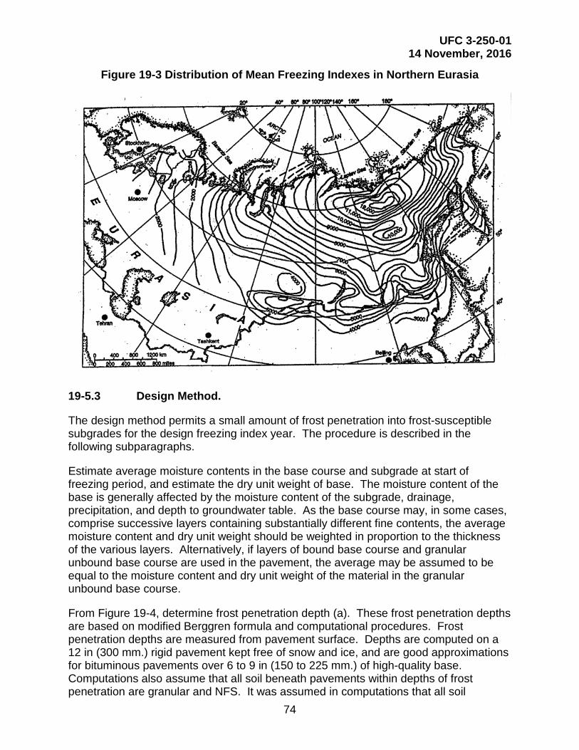
UFC 3-250-01 14 November, 2016
74
Figure 19-3 Distribution of Mean Freezing Indexes in Northern Eurasia
19-5.3 Design Method.
The design method permits a small amount of frost penetration into frost-susceptible subgrades for the design freezing index year. The procedure is described in the following subparagraphs.
Estimate average moisture contents in the base course and subgrade at start of freezing period, and estimate the dry unit weight of base. The moisture content of the base is generally affected by the moisture content of the subgrade, drainage, precipitation, and depth to groundwater table. As the base course may, in some cases, comprise successive layers containing substantially different fine contents, the average moisture content and dry unit weight should be weighted in proportion to the thickness of the various layers. Alternatively, if layers of bound base course and granular unbound base course are used in the pavement, the average may be assumed to be equal to the moisture content and dry unit weight of the material in the granular unbound base course.
From Figure 19-4, determine frost penetration depth (a). These frost penetration depths are based on modified Berggren formula and computational procedures. Frost penetration depths are measured from pavement surface. Depths are computed on a 12 in (300 mm.) rigid pavement kept free of snow and ice, and are good approximations for bituminous pavements over 6 to 9 in (150 to 225 mm.) of high-quality base. Computations also assume that all soil beneath pavements within depths of frost penetration are granular and NFS. It was assumed in computations that all soil

UFC 3-250-01 14 November, 2016
75
moisture freezes at 32 degrees Fahrenheit (0 degrees Celsius). Use straight line interpolation where necessary. For rigid pavements greater than 12 in (300 mm) thick, deduct 10 degree s Fahrenheit days for each 1 in (25 mm) increment of pavement exceeding 12 in (300 mm) from the design freezing index before entering Figure 19-4 to determine frost penetration depth (a). Then add extra concrete pavement thickness to the determined frost penetration.
Compute thickness of unbound base C (Figure 19-5) required for zero frost penetration into the subgrade as follows:
C = a – p
Where
a = frost penetration depth
p = thickness of PCC or bituminous concrete
Compute ratio r = water content of subgradewater content of base
Enter Figure 19-5 with C as the abscissa and, at the applicable value of r, find on the left scale the design base thickness b that will result in the allowable subgrade frost penetration shown on the right scale. If r is greater than 3.0 use 3.0.
19-5.4 Thickness.
The above procedure results in a thickness of material between the frost-susceptible subgrade and the pavement so that for average field conditions subgrade frost penetration of the amount s should not cause excessive differential heave of the pavement surface during the design freezing index year.
19-5.5 Controlling Thickness.
If the combined thickness of pavement and base required by the NFS criteria exceeds the thickness given by the limited subgrade frost penetration procedure of design, adopt the greater thickness given by the NFS criteria as the design thickness.
19-5.6 Effects of Non-frost Susceptible Criteria.
Rigorously follow the base course composition requirements of this chapter. The design base thickness is the total thickness of filter layers, granular unbound base and subbase, and any bound base. For flexible pavements, the thickness of the asphalt surfacing layer and of any bound base, as well as the CBR requirements of each layer of granular unbound base, must be determined using NFS criteria. The thickness of rigid pavement slab must also be determined from NFS criteria.

UFC 3-250-01 14 November, 2016
76
Figure 19-4A Frost Penetration Beneath Pavements

UFC 3-250-01 14 November, 2016
77
Figure 19-4B Frost Penetration Beneath Pavements

UFC 3-250-01 14 November, 2016
78
Figure 19-4C Frost Penetration Beneath Pavements

UFC 3-250-01 14 November, 2016
79
Figure 19-5 Design Depth of Non-frost Susceptible Base for Limited Subgrade Frost Penetration
19-6 REDUCED SUBGRADE STRENGTH.
Thickness design may also be based on the seasonally varying subgrade support that includes sharply reduced values during thawing of soils that have been affected by frost action. Except for pavement projects that are located in regions of low design freezing index, this design procedure usually requires less thickness of pavement and base than that needed for limited subgrade frost penetration. The method may be used for both flexible and rigid pavements wherever the subgrade is reasonably uniform or can be made reasonably horizontally uniform by the required techniques of subgrade preparation. This will prevent or minimize significant or objectionable differential heaving and resultant cracking of pavements. When the reduced subgrade strength method is used for F4 subgrade soils, unusually rigorous control of subgrade

UFC 3-250-01 14 November, 2016
80
preparation must be required. When a thickness determined by the reduced subgrade strength procedure exceeds that determined for limited subgrade frost penetration, the latter smaller value must be used, provided it is at least equal to the thickness required for NFS conditions. In situations where use of the reduced subgrade strength procedure might result in objectionable frost heave, but use of the greater thickness of base course indicated by the limited subgrade frost penetration design procedure is not considered necessary, intermediate design thickness may be used. However, these must be justified on the basis of frost heaving experience developed from existing pavements where climatic and soil conditions are comparable.
19-6.1 Thickness of Flexible Pavements.
In the reduced subgrade strength procedure for design, the design curves in Appendix E should be used for road, street, and parking area design. Do not enter the curves with subgrade CBR values determined by tests or estimates, but instead with the applicable frost-area soil support index from Table 19-3. Frost-area soil support indexes are used as if they were CBR values; the term CBR is not applied to them, however, because being weighted average values for an annual cycle, their value cannot be determined by CBR tests. The soil support index for S1 or S2 material meeting current specifications for base or subbase are determined by conventional CBR tests in the unfrozen state.
General field data and experience indicate that on the relatively narrow embankments of roads and parking areas, reduction in strength of subgrades during frost melting may be less in substantial fills than in cuts because of better drainage conditions and less intense ice segregation. If local field data and experience show this to be the case, then a reduction in combined thickness of pavement and base for frost conditions of up to 10 percent may be permitted for substantial fills.
Flexible pavement criteria for NFS design should also be used to determine the thickness of individual layers in the pavement system, and to ascertain whether it will be advantageous to include one or more layers of bound base in the system. The base course composition requirements set forth must be followed rigorously.
Table 19-3 Frost-Area Soil Support Indexes for Subgrade Soils for Flexible Pavement Design
Frost Group of Subgrade Soil Frost-Area Soil Support Index F1 and S1 9.0 F2 and S2 6.5 F3 and F4 3.5
19-6.2 Thickness of Rigid Pavements.
Where frost is expected to penetrate into a frost-susceptible subgrade beneath a rigid pavement, it is good practice to use a NFS base course at least equal in thickness to the slab. Experience has shown, however, that rigid pavements with only a 4 in (100

UFC 3-250-01 14 November, 2016
81
mm) base have performed well in cold environments with relatively uniform subgrade conditions. Accordingly, where subgrade soils can be made reasonably uniform by the required procedures of subgrade preparation, the minimum thickness of granular unbound base may be reduced to a minimum of 4 in (100 mm). The material must meet the requirements set forth below for free-draining material as well as the criteria for filter under pavement slab. If it does not also meet the criteria for filter over subgrade, a second 4 in (100 mm) layer meeting that criterion must be provided.
Additional granular unbound base course, giving a thickness greater than the minimum specified above, improves pavement performance, giving a higher frost-area index of reaction on the surface of the unbound base Figure 19-6 and permitting a pavement slab of less thickness. Bound base also has significant structural value, and may be used to effect a further reduction in the required thickness of rigid pavement slab. Criteria for determining the required thickness of rigid pavement slabs in combination with a bound base course are contained in Chapter titled Plain Concrete Pavement Design. The requirements for granular unbound base as drainage and filter layers are still applicable.
The thickness of concrete pavement must be determined in accordance with Chapter titled Plain Concrete Pavement Design, using the frost-area index of reaction determined from Figure 19-6. This figure shows the equivalent weighted average index of reaction values for an annual cycle that includes a period of thaw-weakening in relation to the thickness base. Frost-area indexes of reaction are used as if they were moduli of reaction, k, and have the same units. The term modulus of reaction is not applied to them because being weighted average values for an annual cycle, they cannot be determined by a plate-bearing test. If the modulus of reaction, k, determined from tests on the equivalent base course and subgrade, but without frost melting, is numerically smaller than the index of reaction obtained from Figure 19-6, the test value must govern the design.
19-7 FREE-DRAINING MATERIAL DIRECTLY BENEATH BOUND BASE OR SURFACING LAYER.
Base courses may consist of either granular unbound materials or bound base materials or a combination of the two. However, do not place cement or lime bound base directly beneath bituminous pavement unless approved by the Government Civil Engineer. Also, do not place an unbound course between two relatively impervious bound layers. If the combined thickness, in inches, of pavement and contiguous bound base courses is less than 0.09 multiplied by the design air freezing index (this calculation limits the design freezing index at the bottom of the bound base to about 20 degrees Fahrenheit days), not less than 4 in (100 mm) of free-draining material must be placed directly beneath the lower layer of bound base or, if there is no bound base, directly beneath the pavement slab or surface course. The free-draining material must contain 2.0 percent or less, by weight, of grains that can pass the No. 200 sieve, and to meet this requirement, it probably will have to be screened and washed. If the structural criteria for design of the pavement do not require granular unbound base other than the 4 in of free-draining material, then the material in the 4 in (100 mm) layer must be checked for conformance with the filter requirements below. If it fails the test for conformance, an

UFC 3-250-01 14 November, 2016
82
additional layer meeting those requirements must be provided. When using a drainage layer, the drainage layer must extend to an open ditch or subdrain. Pavement drainage is discussed in Chapter titled Design Of Subsurface Pavement Drainage Systems.
Figure 19-6 Frost-Area Index of Reaction for Design of Rigid Roads and Parking Areas
19-8 SOIL STABILIZATION.
19-8.1 Bound Base.
Soils containing only lime as the stabilizer are generally unsuitable for use as base course layers in the upper layers of pavement systems in frost areas. Lime, cement, and a pozzolanic material such as fly ash may be used in some cases to produce a cemented material of high quality that is suitable for upper base course and that has adequate durability and resistance to freeze-thaw action. Soil stabilization mixture design will be based on the procedures set forth in UFC 3-250-11 with the additional

UFC 3-250-01 14 November, 2016
83
requirement that the mixture, after freeze-thaw testing as set forth below, should meet the weight-loss criteria specified in UFC 3-250-11 for cement-stabilized soil. The procedures in ASTM D560/560M should be followed for freeze-thaw testing, except that the specimens should be compacted in a 6 in (150 mm) diameter mold in five layers with a 10 lb (4.5 kg) hammer having an 18 in (450 mm) drop, and that the preparation and curing of the specimens should follow the procedures indicated in UFC 3-250-11 for unconfined compression tests on lime-stabilized soil.
19-8.2 Stabilization with Lime.
If it is economical to use lime-stabilized or lime-modified soil in lower layers of a pavement system, a mixture of adequate durability and resistance to frost action is still necessary. In addition to the requirements for mixture design of lime-stabilized and lime-modified subbase and subgrade materials set forth in UFC 3-250-11, cured specimens should be subjected to the 12 freeze-thaw cycles in ASTM D560/560M (but omitting wire-brushing) or other applicable freeze-thaw procedures. This should be followed by determination of frost-design soil classification by standard laboratory freezing tests. For lime-stabilized or lime-modified soil used in lower layers of the base course, the frost susceptibility, determined after freeze-thaw cycling, should meet the requirements set forth for base course in Chapter titled Flexible Pavement Select Materials And Subbase Courses. If lime-stabilized or lime-modified soil is used as subgrade, its frost susceptibility, determined after freeze-thawing cycling, should be used as the basis of the pavement thickness design if the reduced subgrade strength design method is applied.
19-8.3 Stabilization with Portland Cement.
Cement-stabilized soil meeting the requirements set forth in UFC 3-250-11, including freeze-thaw effects tested under ASTM D560/560M, may be used in frost areas as base course or as stabilized subgrade. Cement-modified soil conforming with the requirements in UFC 3-250-11 also may be used in frost areas. However, in addition to the procedures for mixture design specified in UFC 3-250-11, cured specimens of cement-modified soil should be subjected to the 12 freeze-thaw cycles in ASTM D560/560M (but omitting wire-brushing) or other applicable freeze-thaw procedures. This should be followed by determination of frost design soil classification by standard laboratory freezing tests. For cement-modified soil used in the base course, the frost susceptibility, determined after freeze-thaw cycling, should meet the requirements set forth for base course in Chapter titled Flexible Pavement Select Materials And Subbase Courses. If cement-modified soil is used as subgrade, its frost susceptibility, determined after freeze-thaw cycling, should be used as the basis of the pavement thickness design if the reduced subgrade design method is applied.
19-8.4 Stabilization with Bitumen.
Many different types of soils and aggregates can be successfully stabilized to produce a high quality bound base with a variety of types of bituminous material. In frost areas the use of tar as a binder should be avoided because of its high temperature susceptibility. Asphalts are affected to a lesser extent by temperature changes, but a grade of asphalt suitable to the prevailing climatic conditions should be selected. Excepting these
UFC 3-250-01 14 November, 2016
84
special conditions affecting the suitability of particular types of bitumen, the procedures for mixture design set forth in UFC 3-250-11 and UFC 3-250-03 will ensure that the asphalt-stabilized base will have adequate durability and resistance to moisture and freeze-thaw cycles.
19-9 SUBGRADE REQUIREMENTS.
It is a basic requirement for all pavements constructed in frost areas, that subgrades in which freezing will occur, must be prepared to achieve uniformity of soil conditions by mixing stratified soils, eliminating isolated pockets of soil of higher or lower frost susceptibility, and blending the various types of soils into a single, relatively homogeneous mass. It is not intended to eliminate from the subgrade those soils in which detrimental frost action will occur, but to produce a subgrade of uniform frost susceptibility and thus create conditions tending to make both surface heave and subgrade thaw-weakening as uniform as possible over the paved area. In fill sections the least frost-susceptible soils must be placed in the upper portion of the subgrade by temporarily stockpiling the better materials, cross-hauling, and selective grading. If the upper layers of fill contain frost-susceptible soils, then the finished fill section must be subjected to the subgrade preparation procedures required for cut sections. In cut sections the subgrade must be scarified and excavated to a prescribed depth, and the excavated material must be windrowed and bladed successively until thoroughly blended. The depth of subgrade preparation, measured downward from the top of the subgrade, must be 24 in (600 mm) or two-thirds of the frost penetration less the actual combined thickness of pavement, base course, and subbase course, whichever is less. The prepared subgrade must meet the designated compaction requirements for NFS areas. The construction inspection personnel should be alert to verify that the processing of the subgrade will yield uniform soil conditions throughout the section. To achieve uniformity in some cases, it will be necessary to remove highly frost susceptible soils or soils of low frost susceptibility. In that case, the pockets of soil to be removed should be excavated to the full depth of frost penetration and replaced with material surrounding the frost-susceptible soil being removed.
19-9.1 Exception Conditions.
Exceptions to the basic requirement for subgrade preparation are subgrades known to be NFS to the depth prescribed for subgrade preparation and known to contain no frost-susceptible layers or lenses, as demonstrated and verified by extensive and thorough subsurface investigations and by the performance of nearby existing pavements. Also, fine-grained subgrades containing moisture well in excess of the optimum for compaction, without drainage or other means for reducing the moisture content, and which consequently it is not possible to scarify and re-compacted, are also exceptions.
19-9.2 Treatment of Wet Fine-Grained Subgrades.
If wet fine-grained subgrades exist at the site, it is necessary to achieve frost protection with fill material. This may be done by raising the grade by an amount equal to the depth of subgrade preparation that otherwise would be prescribed, or by undercutting and replacing the wet fine-grained subgrade to that same depth. In either case the fill or backfill material may be NFS material or frost-susceptible material meeting specified
UFC 3-250-01 14 November, 2016
85
requirements. If the fill or backfill material is frost susceptible, it should be subjected to the same subgrade preparation procedures prescribed above.
19-9.3 Cobbles or Boulders.
A critical condition requiring the attention of inspection personnel is the presence of cobbles or boulders in the subgrades. All stones larger than about 6 in (150 mm) in diameter should be removed from fill materials for the full depth of frost penetration, either at the source or as the material is spread in the embankments. Any such large stones exposed during the subgrade preparation work also must be removed, down to the full depth to which subgrade preparation is required. Failure to remove stones or large roots can result in increasingly severe pavement roughness as the stones or roots are heaved gradually upward toward the pavement surface. They eventually break through the surface in extreme cases, necessitating complete reconstruction.
19-9.4 Changes in Soil Conditions.
Abrupt changes in soil conditions must not be permitted. Where the subgrade changes from a cut to a fill section, a wedge of subgrade soil in the cut section with the dimensions shown in Figure C19-7 (Appendix C) should be removed and replaced with fill material. Tapered transitions also are needed at culverts beneath paved areas, but in such cases the transition material should be clean, NFS granular fill. Other pipes under pavement should be similarly treated, and perforated-pipe underdrains should be constructed. These and any other discontinuities in subgrade conditions require the most careful attention of construction inspection personnel, as failure to enforce strict compliance with the requirements for transitions may result in serious pavement distress.
19-9.5 Wet Areas.
Careful attention should be given to wet areas in the subgrade, and special drainage measures should be installed as required. The need for such measures arises most often in road construction, where it may be necessary to provide intercepting drains to prevent infiltration into the subgrade from higher ground adjacent to the road.
19-9.6 Rock Excavation.
In areas where rock excavation is required, consider the character of the rock and seepage conditions. In any case, the excavations should be made so that positive transverse drainage is provided, and no pockets are left on the rock surface that permit ponding of water within the depth of freezing. The irregular groundwater availability created by such conditions may result in markedly irregular heaving under freezing conditions. It may be necessary to fill drainage pockets with lean concrete. At intersections of fills with rock cuts, the tapered transitions mentioned above Figure C19-7 (Appendix C) are essential. Rock subgrades where large quantities of seepage are involved should be blanketed with a highly pervious material to permit the escape of groundwater. Often, the fractures and joints in the rock contain frost-susceptible soils. These materials should be cleaned out of the joints to the depth of frost penetration and
UFC 3-250-01 14 November, 2016
86
replaced with NFS material. If this is impractical, it may be necessary to remove the rock to the full depth of frost penetration.
19-9.7 Rock Subgrades.
An alternative method for treatment of rock subgrades, in-place fragmentation, has been used effectively in road construction. Blast holes 3 to 6 ft (0.9 to 1.8 m) deep are commonly used. They are spaced suitably for achieving thorough fragmentation of the rock to permit effective drainage of groundwater through the shattered rock and out of the zone of freezing in the subgrade. A tapered transition should be provided between the shattered rock cut and the adjacent fill.
19-10 OTHER MEASURES TO REDUCE HEAVE.
Other possible measures to reduce the effects of heave are the use of insulation (Appendix D) to control depth of frost penetration and the use of steel reinforcement to improve the continuity of rigid pavements that may become distorted by frost heave. Reinforcement does not reduce heave nor prevent the cracking resulting from it, but it helps to hold cracks tightly closed and thus reduce pumping through these cracks. Transitions between cut and fill, culverts and drains change in character or stratification of subgrade soils. Subgrade preparation and boulder removal should also receive special attention in field construction control.
19-11 PAVEMENT CRACKING ASSOCIATED WITH FROST HEAVE.
One of the most detrimental effects of frost action on a pavement is surface distortion as the result of differential frost heave or differential loss of strength. These may also lead to random cracking. Deterioration and spalling of the edges of working cracks are causes of uneven surface conditions and sources of debris. Cracking may be reduced by control of such elements as base composition, uniformity and thickness, slab dimensions, subbase and subgrade materials, uniformity of subsurface moisture conditions, and, in special situations, by use of reinforcement and by limitation of pavement type. The importance of uniformity cannot be overemphasized. Where unavoidable discontinuities in subgrade conditions exist, gradual transitions are essential.
19-12 COMPACTION.
Subgrade, subbase, and base course materials must meet the applicable compaction requirements for NFS materials.
19-13 USE OF INSULATION MATERIALS IN PAVEMENTS.
The use of synthetic insulating material within a pavement cross section must have written approval by the Government Civil Engineer, which can also provide advice and assistance in regard to the structural analysis. Criteria for design of pavements containing insulating layers are contained in Appendix D.

UFC 3-250-01 14 November, 2016
87
19-14 DESIGN EXAMPLE HEAVILY TRAFFICKED ROAD.
Appendix G includes examples of design for flexible and rigid pavements in an environment subjected to seasonal frost.
19-15 ALTERNATIVE DESIGNS.
Besides the two methodologies in dealing with seasonal frost, investigate other design alternatives using stabilized layers, including aggregate base course pavements, to determine whether they are more economical than the designs presented above.

UFC 3-250-01 14 November, 2016
88
This Page Intentionally Left Blank

UFC 3-250-01 14 November, 2016
89
CHAPTER 20 DESIGN OF SUBSURFACE PAVEMENT DRAINAGE SYSTEMS
20-1 GENERAL.
In recent years subsurface drainage has received increasing attention, particularly in the area of highway design. A number of studies have been conducted by State Highway Agencies and by the Federal Highway Administration that have resulted in a large number of publications on the subject of subsurface drainage. Appendix A contains a list of publications which contain information pertaining to the design of subsurface drainage for pavements.
20-1.1 Effects of Water on Pavements and Subgrade.
Water has a detrimental effect on pavement performance, primarily by either weakening subsurface materials or erosion of material by free water movement. For flexible pavements the weakening of the base, subbase or subgrade when saturated with water is one of the main causes of pavement failures. In rigid pavement, free water trapped between the concrete surface and an impermeable layer directly beneath the concrete, moves due to pressure caused by loadings. This movement of water, referred to as pumping, erodes the subsurface material creating voids under the concrete surface. In frost areas water contributes to frost damage by heaving during freezing and loss of subgrade support during thawing. Poor subsurface drainage can also contribute to secondary damage such as ‘D’ cracking or swelling of subsurface materials.
20-1.2 Traffic Effects.
The type, speed and volume of traffic will influence the criteria used in the design of pavement drainage systems. For rigid pavements pumping is greatly increased as the volume and speed of the traffic increases. For flexible pavements the buildup of pore pressures as a result of high volume, high speed traffic is a primary cause of the weakening of the pavement structure.
20-1.3 Sources of Water.
The two sources of water to be considered are from infiltration and subterranean water. Infiltration is the most important source of water and is the source of most concern in this document. Subterranean water is important in frost areas and areas of very high groundwater table or areas of artesian water. In many areas, perched groundwater may develop under pavements due to a reduced rate of evaporation of the water from the surface. In frost areas, free water collects under the surface by freeze-thaw action.
20-1.3.1 Infiltration.
Infiltration is surface water which enters the pavement from the surface through cracks or joints in the pavement, through the joint between the pavement and shoulder, through pores in the pavement, and through shoulders and adjacent areas. Since surface infiltration is the principal source of water, it is the source needing greatest control measures.

UFC 3-250-01 14 November, 2016
90
20-1.3.2 Subterranean Groundwater.
Subterranean groundwater can be a source of water from a high groundwater table, capillary forces, artesian pressure, and freeze-thaw action. Groundwater tables rise and fall depending upon the relation between infiltration, absorption, evaporation and groundwater flow. Seasonal fluctuations are normal because of differences in the amount of precipitation and maybe relatively large in some localities. Prolonged drought or wet periods will cause large fluctuations in the groundwater level. Subterranean source of water is particularly important in areas of frost action when large volumes of water can be drawn into the pavement structure during the formation of ice lenses. For large paved areas the evaporation from the surface is greatly reduced which causes saturation of the pavement structure by capillary forces. Also, if impervious layers exist beneath the pavement, perched groundwater can be present or develop from water entering the pavement through infiltration. This perched groundwater then becomes a subterranean source of water. In general, the presence of near surface subterranean water must be identified during soil exploration and drainage facilities designed to mitigate the influence of subterranean water.
20-1.3.3 Freeze-Thaw.
Freeze-thaw action can result in large amounts of groundwater being drawn into the pavement structure. In freeze-thaw conditions, groundwater flows to the freeze front by capillary action. Repeated cycles of freeze-thaw result in the growth of ice lenses that can cause heave in the pavement structure. Heaves in soils as great as 60 percent are not uncommon and under laboratory conditions, heaves of as much as 300 percent have been recorded. The formation of ice lenses in the pavement structure affects the structural integrity of the pavement structure in two very detrimental ways. One effect is the formation of the ice lenses causes a loss of density of the pavement materials resulting in strength loss of the pavement materials. A second effect is thawing of the ice results in a large volume of free water that must be drained from the pavement. Because thawing usually occurs simultaneously from both the top and bottom of the pavement structure, the free water can be trapped within the pavement structural. Providing adequate drainage minimizes pumping and promotes the restoration of pavement strength. In the design of sub-drain systems in frost areas, free water in both the upper and lower sections of the pavement must be considered.
20-1.4 Classification of Subdrain Facilities
Subdrain facilities can be categorized into two functional categories, one to control infiltration, and one to control groundwater. An infiltration control system is designed to intercept and remove water that enters the pavement from precipitation or surface flow. An important function of this system is to keep water from being trapped between impermeable layers. A groundwater control system is designed to reduce water movement into subgrades and pavement sections by controlling the flow of groundwater or by lowering the water table. Often, subdrains are required to perform both functions, and the two subdrain functions can be combined into a single subdrain system. Figure C20-1 and Figure C20-2 (Appendix C) illustrate examples of infiltration and groundwater control systems.

UFC 3-250-01 14 November, 2016
91
20-1.5 Subsurface Drainage Requirements.
The determination of the subsurface soil properties and water condition is a prerequisite for the satisfactory design of a subsurface drainage system. Field explorations and borings made in connection with the project design should include the following investigations pertinent to subsurface drainage. A topographic map of the proposed area and the surrounding vicinity should be prepared indicating all streams, ditches, wells, and natural reservoirs. The analysis of aerial photographs of the areas selected for construction may furnish valuable information on general soil and groundwater conditions. An aerial photograph presents a graphic record of the extent, boundaries, and surface features of soil patterns occurring at the surface of the ground. The presence of vegetation, the slopes of a valley, the colorless monotony of sand plains, the farming patterns, the drainage pattern, gullies, eroded lands, and evidences of the works of man are revealed in detail by aerial photographs. The use of aerial photographs may supplement both the detail and knowledge gained in topographic survey and ground explorations. The sampling and exploratory work can be made more rapid and effective after analysis of aerial photographs has developed the general soil features. The location and depth of permanent and perched groundwater tables may be sufficiently shallow to influence the design. The season of the year and rainfall cycle will measurably affect the depth to the groundwater table. In many locations, information may be obtained from residents of the surrounding areas regarding the behavior of wells and springs and other evidences of surface or subsurface water. The soil properties investigated for other purposes in connection with the design will supply information that can be used for the design of the drainage system. It may be necessary to supplement these explorations at locations of subsurface drainage structures and in areas where soil information is incomplete for design of the drainage system.
20-1.6 Laboratory Tests.
The design of subsurface drainage structures requires knowledge of the following soil properties: strength, compressibility, swell and dispersion characteristics, the in situ and compacted unit dry weights, the coefficient of permeability, the in situ water content, specific gravity, grain-size distribution, and the effective void ratio. These soil properties may be satisfactorily determined by experienced soil technicians through laboratory tests. The final selected soil properties for design purposes may be expressed as a range, one extreme representing a maximum value and the other a minimum value. The true value should be between these two extremes, but it may approach or equal one or the other, depending upon the variation within a soil stratum.
20-1.7 Drainage of Water from Soil.
The quantity of water removed by a drain varies depending on the type of soil and location of the drain with respect to the groundwater table. All the water contained in a given specimen cannot be removed by gravity flow since water retained as thin films adhering to the soil particles and held in the voids by capillarity do not drain. Consequently, to determine the volume of water that can be removed from a soil in a given time, the effective porosity as well as the permeability must be known. Limited

UFC 3-250-01 14 November, 2016
92
effective porosity test data for well-graded base course materials, such as bank-run sands and gravels, indicate a value for effective porosity of not more than 0.15. Uniformly graded soils such as medium coarse sands, may have an effective porosity of not more than 0.25. Open graded aggregate used for drainage layers will have an effective porosity of between 0.25 and 0.35.
20-2 PRINCIPLES OF PAVEMENT DRAINAGE.
20-2.1 Flow of Water Through Soils.
The flow of water through soils is expressed by Darcy’s empirical law which states that the velocity of flow (v) is directly proportional to the hydraulic gradient (i). This law can be expressed as:
Equation 20-1 = ×v k i
Where k is the coefficient of proportionality known as the coefficient-of-permeability, Equation 20-1 can be expanded to obtain the rate of flow through an area of soil (A). The equation for the rate of flow (Q) is:
Equation 20-2 = × ×Q k i A
According to Darcy’s law, the velocity of flow and the quantity of discharge through a porous media are directly proportional to the hydraulic gradient. For this condition to be true, flow must be laminar or non-turbulent. Investigations have found that Darcy’s law is valid for a wide range of soils and hydraulic gradients. However, in developing criteria for subsurface drainage, liberal margins have been applied to allow for turbulent flow. The criteria and uncertainty depend heavily on the permeability of the soils involved in the pavement structure. It is therefore useful to examine the influence of various factors on the permeability of soils. In examining permeability of soils in regard to pavement drainage, the materials of most concern are base and subbase aggregate and aggregate used as drainage layers.
20-2.2 Factors Affecting Permeability.
20-2.2.1 Coefficient of Permeability.
The value of permeability depends primarily on the characteristics of the permeable materials, but it is also a function of the properties of the fluid. An equation (after Taylor) demonstrating the influence of the soil and pore fluid properties on permeability was developed based on flow through porous media similar to flow through a bundle of capillary tubes. This equation is as follows:

UFC 3-250-01 14 November, 2016
93
Equation 20-3 ( )
−⋅
⋅⋅⋅=
eeCDk s 1
32
µγ
where
k=the coefficient of permeability
Ds=Hazen’s effective particle diameter
C= shape factor
γ=unit weight of pore fluid
μ=viscosity of pore fluid
e=void ratio
20-2.2.2 Effect of Pore Fluid and Temperature.
In the design of subsurface drainage systems for pavements, the primary pore fluid of concern is water. Therefore, when permeability is mentioned in this chapter, water is assumed to be the pore fluid. Equation 20-3 indicates that the permeability is directly proportional to the unit weight of water and inversely proportional to the viscosity. The unit weight of water is essentially constant, but the viscosity of water will vary with temperature. Over the widest range in temperatures ordinarily encountered in seepage problems, viscosity varies about 100 percent. Although this variation seems large, it can be insignificant when considered in the context of the variations which can occur with changes in material properties.
20-2.2.3 Effect of Grain Size and Void Ratio.
It is logical that the smaller the grain size the smaller the voids that constitute the flow channels, and hence the lower the permeability. Equation 20-3 suggests that permeability varies with the square of the effective particle diameter and the cube of the void ratio. Since the void ratio is, for the most part a function of the material gradation, the influence of effective particle diameter will be magnified. Consider that when the effective particle size increases from No. 200 (0.08 mm) to No. 16 (1.2 mm) the permeability, according to equation 20-3, would increase by a factor of about 250. Assuming the increase in effective particle size would result in an increase in the void ratio by a minimum of two times then the permeability due to the increase in void ratio would be by a factor of 8. Thus the total increase in permeability due to the increase in the effective particle size and increase in void ratio would be by a factor of about 2000. Also, the shape of the void spaces has a marked influence on the permeability. As a result, the relationships between grain size, void ratio and permeability are complex. Intuition and experimental test data suggest that the finer particles in a soil have the most influence on permeability. The coefficient of permeability of sand and gravel materials, graded between limits usually specified for pavement bases and subbases, depends principally upon the percentage by weight of particles passing the No. 200

UFC 3-250-01 14 November, 2016
94
sieve. Table 20-1 provides estimates of the permeability for these materials for various amounts of material finer than the No. 200 sieve.
Table 20-1 Coefficient of Permeability for Sand and Gravel Materials (Coefficient of 55)
Percent by Weight Passing No. 200 Sieve
Permeability for Remolded Samples mm/sec ft/min
3 5×10⁻¹ 10-1
5 5×10⁻² 10-2
10 5×10⁻³ 10-3
15 5×10⁻⁴ 10-4
20 5×10⁻⁵ 10-5
The volume of water that a soil mass is capable of holding is directly related to the void ratio. Not all water contained in a soil can be drained by gravity flow since water retained as thin films adhering to the soil particles and held by capillarity do not drain. Consequently, to determine the volume of water that can be removed from a soil the effective porosity (ne) must be known. The effective porosity is defined as the ratio of the volume of the voids that can be drained under gravity flow to the total volume of soil, and can be expressed mathematically as
Equation 20-4 ( )1 1de S e
S W
n G WG
= - + ××γγ
where
γd=dry density of the soil
GS= specific gravity of solids
γW=unit weight of water
We= effective water content (after the soil has drained) expressed as a decimal fraction relative to dry weight
Limited effective porosity test data for well-graded base course materials, such as bank-run sands and gravels, indicate a value for effective porosity of not more than 0.15. Uniformly graded medium or coarse sands, may have an effective porosity of not more than 0.25 while for a uniformly graded aggregate, such as would be used in a drainage layer, the effective porosity may be above 0.25.
20-2.2.4 Effect of Structure and Stratification.
Generally, in situ soils show a certain amount of stratification or a heterogeneous structure. Water deposited soils usually exhibit a series of horizontal layers that vary in grain-size distribution and permeability, and generally these deposits are more
UFC 3-250-01 14 November, 2016
95
permeable in the horizontal than in the vertical direction. In pavement construction the subgrade, subbase, and base materials are placed and compacted in horizontal layers which result in having a different permeability in the vertical direction than in the horizontal direction. The vertical drainage of water from a pavement can be disrupted by a single relatively impermeable layer. For most pavements the subgrades have a very low permeability compared to the base and subbase materials. Therefore, water in the pavement structure can best be removed by horizontal flow. For a layered pavement system the effective horizontal permeability is obtained from a weighted average of the layer permeability by the formula.
Equation 20-5 ×× + × + × +=+ + +
1 1 2 2 3 3
1 2 3
(k d k d k d ...)k(d d d ...)
Where:
k = the effective horizontal permeability
1 2 3k ,k ,k ...= the coefficients of horizontal permeability of individual layers
1 2 3d ,d ,d ...= thicknesses of the individual layers
When a drainage layer is used in the pavement section, the permeability of the drainage material will likely be several orders of magnitude greater than the other materials in the section. Since water flow is proportional to permeability, the flow of water from the pavement section can be computed based only on the characteristics of the drainage layer.
20-2.3 Quantity and Rate of Subsurface Flow.
20-2.3.1 General.
Water flowing from the pavement section may come from infiltration through the pavement surface, groundwater or both. Normally groundwater flows into collector drains from the subgrade and will be an insignificant flow compared to the flow coming from infiltration. The computation of the groundwater flow is beyond the scope of this UFC. The volume of surface water infiltration flowing into the pavement depends on factors such as type and condition of surface, length, intensity of rainfall, properties of the drainage layer, hydraulic gradient, time allowed for drainage and the drained area. Consider all these factors in the design of the subsurface drainage system.
20-2.3.2 Effects of Pavement Surface.
The type and condition of the pavement surface has considerable influence on the volume of water entering the pavement structure. In the design of surface drainage facilities, assume all rain falling on paved surfaces to be runoff. For new well designed and constructed pavements, the assumption of 90 percent runoff is probably a good conservative assumption for the design of surface drainage facilities. For design of the subsurface drainage facilities, the design should be based on the infiltration rate for a

UFC 3-250-01 14 November, 2016
96
deteriorated pavement. Studies have shown that for badly deteriorated pavements well over 50 percent of the rainfall can flow through the pavement surface. Since it is almost impossible to completely maintain a pavement over its life and since water may also enter from the shoulders, the infiltration rate for a deteriorated pavement must be used.
20-2.3.3 Effects of Rainfall.
The volume of water entering the pavement is directly proportional to the intensity and length of the rainfall. Relatively low intensity rainfalls can be used for designing the subsurface drainage facilities because high intensity rainfalls do not greatly increase the adverse effect of water on pavement performance. The excess rainfall would, once the base and subbase are saturated, run off as surface drainage. For this reason a seemingly non-conservative design rainfall can be selected.
20-2.3.4 Capacity of Drainage Layers.
If water enters the pavement structure at a greater rate than the discharge rate, the pavement structure becomes saturated. The design of horizontal drainage layers for the pavement structure is based, in part, on the drainage layer serving as a reservoir for the excess water entering the pavement. The capacity of the drainage layer as a reservoir is a function of the storage capacity of the drainage layer plus the amount of water which drains from the layer during a rain event. The storage capacity of the drainage layer is a function of the effective porosity of the drainage material and the thickness of the drainage layer. The storage capacity of the drainage layer qs in terms of depth of water per unit area is computed by:
Equation 20-6 = ×q n hs e
where
ne=the effective porosity
h=the thickness of the drainage layer
In the equation the dimensions of the qs will be the same as the dimensions of the h. If all the water does not drain from the drainage layer, then the storage capacity is reduced by the amount of water in the layer at the start of the rain event. The criterion for design of the drainage layer calls for 85 percent of the water to be drained from the drainage layer within 24 hours; therefore it is conservatively assumed that only 85 percent of the storage volume will be available at the beginning of a rain event. To account for the possibility of water in the layer at the beginning of a rain event, equation 20-6 is modified to be:

UFC 3-250-01 14 November, 2016
97
Equation 20-7 = × ×0 85s eq . n h
The amount of water (qd) which will drain from the drainage layer during the rain event may be estimated using the equation
Equation 20-8 × × ×=
×2dt k i hq
L
Where:
t = duration of the rain event
L = length of the drain path
k = permeability of the drainage layer
i = slope of the drainage layer
h = thickness of the drainage layer
In these equations the dimensions of s dq ,q ,t ,k,h and L should be consistent. The total
capacity (q ) of the drainage layer will be the sum of sq and dq resulting in the following equation for the capacity
Equation 20-9 +⋅⋅= )85.0( hnq e
⋅⋅⋅⋅
Lhikt
2
Knowing the intensity of water entering the pavement, equation 20-9 can be used to estimate the thickness of the drainage layer such that the drainage layer will have the capacity for a given design rain event. For most situations the amount of water draining from the drainage layer is small compared to the storage capacity. Therefore, in most cases, equation 20-7 can be used in estimating the thickness required for the drainage layer. For most highway designs a 4 in (100 mm) thick drainage layer will be sufficient.
20-2.3.5 Time for Drainage.
It is desirable that the water be drained from the base and subbase layers as rapidly as possible. The time for drainage of these layers is a function of the effective porosity, length of the drainage path, thickness of the layers, slope of the drainage path, and permeability of the layers, refer to Figure C20-3 (Appendix C) for pavement geometry. Until 1994, criteria specified that the base and subbase obtain a degree of 50 percent drainage within 10 days. The equation for computing time for 50 percent drainage is:
UFC 3-250-01 14 November, 2016
98
Equation 20-10 ( )( )
2
50 2e
o
n DT
k H×
=× ×
Where:
50T = time for 50 percent drainage
en = effective porosity of the soil
k = coefficient of permeability
D , oH andH = base and subbase geometry dimensions as shown in Figure C20-3 (Appendix C).
The dimensions of time k, Ho, H and D must be consistent. If In Figure C20-3 (Appendix C) the thickness of the drainage layer is small compared the length of the drainage
path, the slope of the drainage path ( i ) can represent the value of
DH o
therefore
equation 20-10 can be written
Equation 20-11 50 2en DTi k×=
× ×
Experience has shown that base and subbase materials, when compacted to densities required in pavement construction, seldom have sufficient permeability to meet the 10 day drainage criterion. In such pavements the base and subbase materials become saturated causing a reduced pavement life. When a drainage layer is incorporated into the pavement structure to improve pavement drainage, the criterion for design of the drainage layer must be that the drainage layer must reach a degree of drainage of 85 percent within 24 hr. The time for 85 percent drainage is about twice the time for 50 percent drainage. The time for 85 percent drainage ( 85T ) is computed by
Equation 20-12 85en DTi k
×=×
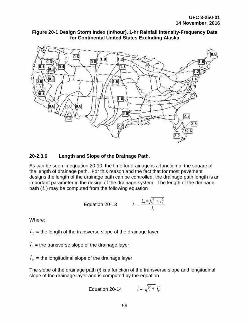
UFC 3-250-01 14 November, 2016
99
Figure 20-1 Design Storm Index (in/hour), 1-hr Rainfall Intensity-Frequency Data for Continental United States Excluding Alaska
20-2.3.6 Length and Slope of the Drainage Path.
As can be seen in equation 20-10, the time for drainage is a function of the square of the length of drainage path. For this reason and the fact that for most pavement designs the length of the drainage path can be controlled, the drainage path length is an important parameter in the design of the drainage system. The length of the drainage path (L ) may be computed from the following equation
Equation 20-13 2 2
t t e
t
L i iL
i× +
=
Where:
tL = the length of the transverse slope of the drainage layer
ti = the transverse slope of the drainage layer
ei = the longitudinal slope of the drainage layer
The slope of the drainage path (i) is a function of the transverse slope and longitudinal slope of the drainage layer and is computed by the equation
Equation 20-14 2 2t ei i i= +
UFC 3-250-01 14 November, 2016
100
20-2.3.7 Rate of Flow.
The edge drains for pavements having drainage layers must be designed to handle the maximum rate of flow from the drainage layer. This maximum rate of flow will be obtained when the drainage layer is flowing full and may be estimated using equation 20-2.
20-2.4 Use of Drainage Layers.
20-2.4.1 Purpose of Drainage Layers.
Special drainage layers may be used to promote horizontal drainage of water from pavements, prevent the buildup of hydrostatic water pressure, and facilitate the drainage of water generated by cycles of freeze-thaw.
20-2.4.2 Placement of Drainage Layers.
In rigid pavements the drainage layer will generally be placed directly beneath the concrete slab. In this location, the drainage layer will intercept surface water entering through cracks and joints, and permit rapid drainage of the water away from the bottom of the concrete slab. In flexible pavements the drainage layer will normally be placed beneath the base. In placing the drainage layer beneath the base the stresses on the drainage layer are reduced to an acceptable level and drainage is provided for the base course. Placement of the drainage layer in areas of frost penetration requires special consideration, in that, during the thaw it is likely that free water will be generated as the thaw front advances up from the bottom as well as down from the top. For frost areas it is possible that the drainage layer is best placed beneath any good draining NFS material. Another consideration in the design of subsurface drainage systems in frost areas is that it is possible for the drains to become blocked by snow and ice.
20-2.4.3 Permeability Requirements for the Drainage Layer.
The material for drainage layers in pavements must be of sufficient permeability to provide rapid drainage and rapidly dissipate water pressure and yet provide sufficient strength and stability to withstand load induced stresses. There is a trade-off between strength or stability and permeability; therefore the material for the drainage layers should have the minimum permeability for the required drainage application. For most applications a material (referred to as a rapid draining material) with a permeability of 1,000 ft/day (300 m/day) will provide sufficient drainage.
20-2.5 Use of Filters.
20-2.5.1 Purpose of Filters in Pavement Structures.
The purpose of filters in pavement structures is to prevent the movement of soil (piping) yet allow the flow of water from one material to another. The need for a filter is dictated by the existence of water flow from a fine grain material to a coarse gain material generating a potential for piping of the fine grain material. The principal location in the pavement structure where a flow from a fine grain material into a coarse grain material is water flowing from the base, subbase, or subgrade into the coarse aggregate

UFC 3-250-01 14 November, 2016
101
surrounding the drain pipe. Thus, the principal use of a filter in a pavement system is to prevent piping into the drain pipe. Although rare, the possibility exists for hydrostatic head forcing a flow of water upward from the subbase or subgrade into the pavement drainage layer. For such a condition it is necessary to design a filter to separate the drainage layer from the finer material.
20-2.5.2 Piping Criteria.
The criteria for preventing movement of particles from the soil or granular material to be drained into the drainage material are:
5drained be to material of size percent 85material filter or drainage of size percent 15 ≤
and
25drained be to material of size percent 50material filter or drainage of size percent 50 ≤
The criteria given above are used when protecting all soils except clays without sand or silt particles. For these soils, the 15 percent size of drainage or filter material may be as great as 0.4 mm and the d50 criteria will be disregarded.
20-2.5.3 Permeability Requirements.
To assure that the filter material is sufficiently permeable to permit passage of water without hydrostatic pressure buildup, the following requirement should be met:
5drained be to material of size percent 15material filter of size percent 15 ≥
20-2.6 Use of Separation Layers.
When drainage layers are used in pavement systems, the drainage layers must be separated from fine grain subgrade materials to prevent penetration of the drainage material into the subgrade or pumping of fines from the subgrade into the drainage layer. The separation layer is different from a filter in that there is no requirement, except during frost thaw, to protect against water flowing from the subgrade through the layer into the drainage layer.
20-2.6.1 Requirements for Separation Layers.
The main requirements of the separation layer are that the material for the separation layer have sufficient strength to prevent the coarse aggregate of the drainage layer from being pushed into the fine material of the subgrade and that the material have sufficient permeability to prevent buildup of hydrostatic pressure in the subgrade. To satisfy the strength requirements the material of the separation layer should have a minimum CBR of 50. To allow for release of hydrostatic pressure in the subgrade, the separation layer should have a higher permeability than that of the subgrade. This would not normally

UFC 3-250-01 14 November, 2016
102
be a problem because the permeability of subgrades are orders of magnitude less than the permeability of a 50 CBR material but to ensure sufficient permeability the permeability requirements of a filter would apply.
20-2.7 Use of Geotextiles.
20-2.7.1 Purpose of Geotextiles.
Geotextiles (engineering fabrics) may be used to replace either the filter or the separation layer. The principal use of geotextiles is the filter around the pipe for the edge drain. Although geotextiles can be used as a replacement for the separation layer, geotextile adds no structure strength to the pavement; therefore this practice is not recommended.
20-2.7.2 Requirements of the Geotextiles for Filters.
When geotextiles are to serve as a filter lining the edge drain trench, the most important function of the filter is to keep fines from entering the edge drain system. For pavement systems having drainage layers there is little requirement for water flow through the fabric; therefore for most applications, it is better to have a heavier fabric than would normally be used as a filter. Since drainage layers have a very high permeability, geotextile fabric should never be placed between the drainage layer and the edge drain. The permeability of geotextiles is governed by the size of the openings in the fabric which is specified in terms of the apparent opening size (AOS) in millimeters. For use as a filter for the trench of the edge drain the AOS of the geotextile should always be equal to or less than 0.212 mm. For geotextiles used as filters with drains installed to intercept groundwater flow in subsurface aquifers the geotextile should be selected based on criteria similar to the criteria used to design a granular filter.
20-2.7.3 Requirements for Geotextiles Used for Separation.
Geotextiles used as separation layers beneath drainage layers should be selected based primarily on survivability of the geotextiles with somewhat less emphasis placed on the AOS. When used as a separation layer the geotextile survivability should be rated very high by the rating scheme given by AASHTO M 288. This ensures the survival of the geotextiles under the stress of traffic during the life of the pavement. To ensure that fines will not pump into the drainage layer yet allow water flow to prevent hydrostatic pressure the AOS of the geotextile must be equal to or less than 0.212 mm and also equal to or greater than 0.125 mm.
20-3 DESIGN OF THE PAVEMENT SUBSURFACE DRAINAGE SYSTEM.
20-3.1 General.
Provide a pavement subsurface drainage system for the rapid removal of surface water and water generated by freeze-thaw action. Although the primary emphasis will be on removing water from under the pavement, there may be occasions when the system will also serve as interceptor drain for groundwater.
UFC 3-250-01 14 November, 2016
103
20-3.2 Methods.
For most pavement structures, water is to be removed by the use of a special drainage layer which allows the rapid horizontal drainage of water. The drainage layer must be designed to handle surface infiltration from a design storm and withstand the stress of traffic. A separation layer must be provided to prevent intrusion of fines from the subgrade or subbase into the drainage layer and facilitate construction of the drainage layer. The drainage layers should feed into a collection system consisting of trenches with a drain pipe, backfill, and filter. The collection system must be designed to maintain progressively greater outflow capabilities in the direction of flow. The outlet for the subsurface drains should be properly located or protected to prevent backflow from the surface drainage system. Some pavements may not require a drainage system in that the subgrade may have sufficient permeability for the water to drain vertically into the subgrade. In addition, some pavements designed for very light traffic, may not justify the expense of a subsurface drain system. Even for the pavements designed for very light traffic care must be taken to insure that base and subbase material are free draining and that water will be not trapped in the pavement structure. For pavements not having collection systems the base and subbase must daylight at the shoulders.
20-3.3 Design Prerequisites.
For the satisfactory design of a subsurface drainage system, the designer must have an understanding of environmental conditions, subsurface soil properties and groundwater conditions.
20-3.3.1 Environmental Conditions.
Temperature and rainfall data applicable to the local area should be obtained and studied. The depth of frost penetration is an important factor in the design of a subsurface drainage. For most areas the approximate depth of frost penetration can be determined by referring to UFC 3-260-02 or by using the computer program for frost analysis. Rainfall data are used to determine the volume of water to be handled by the subsurface drainage system. The data can be obtained from local weather stations or by the use of Figure 20-1.
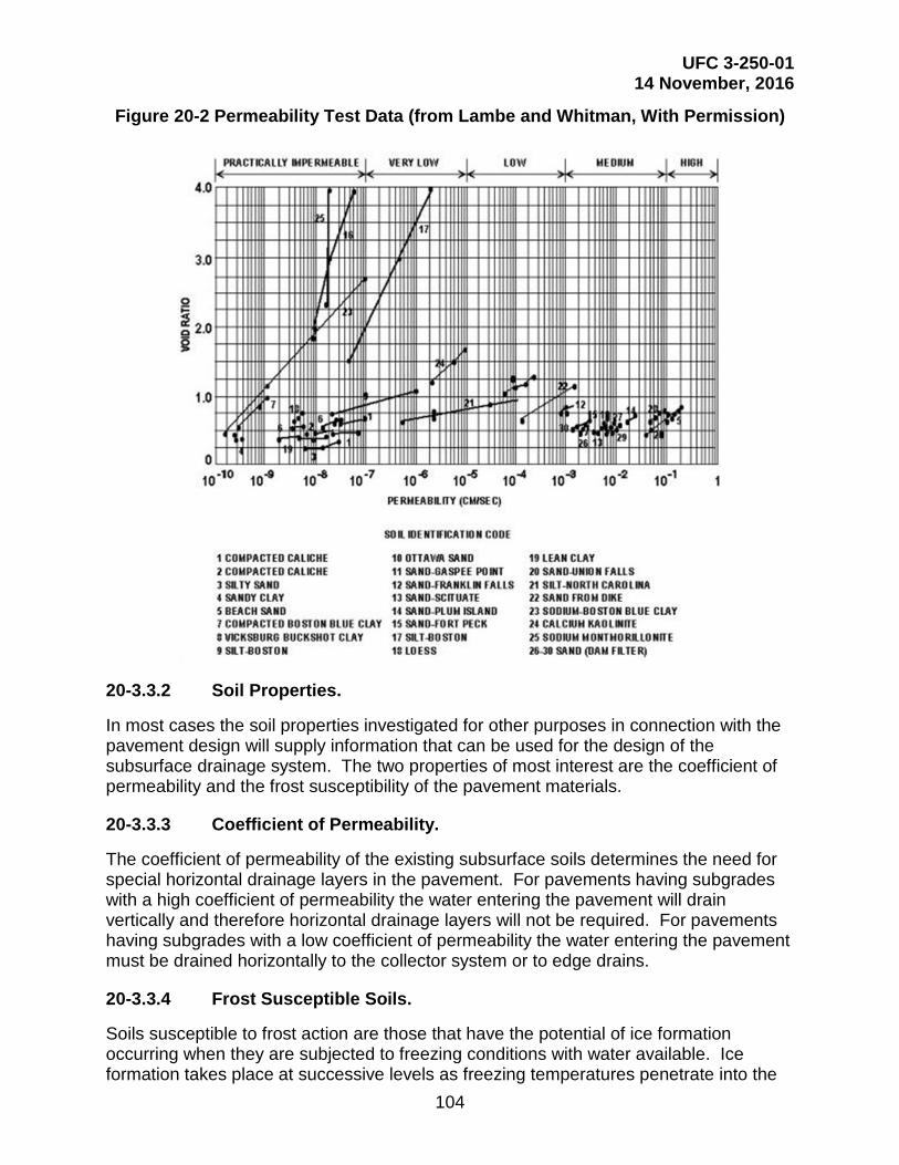
UFC 3-250-01 14 November, 2016
104
Figure 20-2 Permeability Test Data (from Lambe and Whitman, With Permission)
20-3.3.2 Soil Properties.
In most cases the soil properties investigated for other purposes in connection with the pavement design will supply information that can be used for the design of the subsurface drainage system. The two properties of most interest are the coefficient of permeability and the frost susceptibility of the pavement materials.
20-3.3.3 Coefficient of Permeability.
The coefficient of permeability of the existing subsurface soils determines the need for special horizontal drainage layers in the pavement. For pavements having subgrades with a high coefficient of permeability the water entering the pavement will drain vertically and therefore horizontal drainage layers will not be required. For pavements having subgrades with a low coefficient of permeability the water entering the pavement must be drained horizontally to the collector system or to edge drains.
20-3.3.4 Frost Susceptible Soils.
Soils susceptible to frost action are those that have the potential of ice formation occurring when they are subjected to freezing conditions with water available. Ice formation takes place at successive levels as freezing temperatures penetrate into the

UFC 3-250-01 14 November, 2016
105
ground. Soils having a high capillary rate and low cohesive nature act as a wick in feeding water to ice lenses. Soils are placed into groups according to the degree of frost susceptibility as shown in Table 20-2. Because a large volume of free water is generated during the thawing of ice lenses, horizontal drainage layers are required to permit the escape of the water from the pavement structure and thus facilitate the restoration of the pavement strength.
Table 20-2 Frost Susceptible Soils
Typical Soil
Frost Group Type of Soil
Percent Finer than 0.02 mm
by Weight Types Under Unified Soil
Classification System F1 Gravelly Soils 6-10 GW-GM, GP-GM,
GW-GC, GP-GC F2 (a) Gravelly Soils
(b) Sands 10-20 6-15
GM, GC, GM-GC SM, SC, SW-SM, SP-SM, SW-SC, SP-SC, SM-SC
F3 (a) Gravelly Soils (b) Sands, except very fine silty sands (c) Clays (PI > 12)
> 20 > 15
--
GM, GC, GM-GC SM, SC, SM-SC
CL, CH, ML-CL
F4 (a) Silts (b) Very fine sands (c) Clays (PI < 12) (d) Varved clays and other fine grained, with banded sediments
-- > 15
-- --
ML, MH, ML-CL SM, SC, SM-SC
CL, ML-CL CL or CH layered ML, MH, SM, SC SM-SC or ML-CL
20-3.3.5 Sources for Data
The field explorations made in connection with the project design should include a topographic map of the proposed pavement facility and surrounding vicinity indicating all streams, ditches, wells, and natural reservoirs. An analysis of aerial photographs should be conducted for information on general soil and groundwater conditions. Borings taken during the soil exploration must provide depth to groundwater tables and subgrade soil types. Typical values of permeability for subgrade soils can be obtained from Figure 20-2. Although the value of permeability determined from Figure 20-2 must be considered only an estimate, the value should be sufficiently accurate to determine if subsurface drainage is required for the pavement.

UFC 3-250-01 14 November, 2016
106
For the permeability of granular materials, estimates of the permeability may be determined from the following equations:
Equation 20-15 ( ) ( )( )
1 478 6 65410
0 597200
217 5 . .
.
. D nk
P× ×
= (mm/sec)
or
Equation 20-16 ( ) ( ) ( )
( )
1 478 6 6545100 597
200
6 214 10 . .
.
. D nk
P
´ × ×= (ft/day)
Where:
n = porosity =Gw
d
⋅−γγ
1
G = specific gravity of solids (assumed 2.7)
γd = dry density of material
γw = density of water
10D = effective grain size at 10 percent passing in millimeters
200P = percent passing No. 200 (0.08 mm) sieve
For the most part the permeability needed for design of the drainage layer will be assigned based on the gradation of the drainage material. In some cases, laboratory permeability tests may be necessary, but it is cautioned that the permeability of very open granular materials is very sensitive to test methods, methods of compaction and gradation of the sample. Therefore, conservative drainage layer permeability values should be used for design.
20-3.4 Criteria for Subsurface Drain Systems.
Not all pavements require a subsurface drain system either because the subgrade is sufficiently permeable to allow vertical drainage of water into the subgrade or the pavement structure does not justify the expense of a subsurface drain system. For pavements having a subgrade with permeability greater than 20 ft/day (6 m/day), one can assume that the vertical drainage is sufficient to not require a drainage system. In addition to the above exemption for the requirement for drainage systems, flexible pavements having total thickness of structure above the subgrade of 8 in (200 mm) or less are not required to have a drainage system. All pavements not meeting the above criteria are required to have a subsurface drainage system. Even if a pavement meets the exemption requirements, a drainage analysis should be conducted for possible

UFC 3-250-01 14 November, 2016
107
benefits for including the drainage system. For rigid pavements in particular, care should be taken to ensure water is drained rapidly from the bottom of the slab and that the material directly beneath the concrete slab is not susceptible to pumping.
20-3.4.1 Surface Water Inflow.
The subsurface drainage of the pavement is to be designed to handle surface water infiltrated from a design storm of 1 hour duration at an expected return frequency of 2 yr. The design storm index for different parts of the U.S. can be obtained from Figure 20-1. Determine the inflow by multiplying the design storm index (R ) times an infiltration coefficient (F ). The infiltration coefficient varies over the life of the pavement depending on the type of pavement, surface drainage, pavement maintenance, and structural condition of the pavement. Since the determination of a precise value of the infiltration coefficient for a particular pavement is very difficult, a value of 0.5 may be assumed for design.
20-3.4.2 Length and Slope of Drainage Path.
The length of the drainage path is measured along the slope of the drainage layer from the crest of the slope to where the water will exit the drainage layer. In simple terms, the length of the drainage path is the maximum distance water will travel in the drainage layer. The length of the drainage path (L) in feet (meters) is to be computed by equation 20-13, where and the slope (i) of the drainage path is to be computed by equation 20-14.
20-3.4.3 Thickness of Drainage Layer.
The thickness of the drainage layer is computed such that the capacity of the drainage layer is equal to or greater than the infiltration from the design storm. When the length of the drainage path (L) is in feet (meters), the design storm index (R) is in feet/hour (meters/hour), the permeability of the drainage layer (k) is in feet/hour (meters/hour), and the length of the design storm (t) is in hours, the equation for computing the thickness (H) in feet (meters) is
Equation 20-17 ( ) ( )2
1 7 e
F R L tH. n L k i t
× × × ×=× × + × ×
The effective porosity (ne), the infiltration coefficient (F) and the slope of the drainage path (i) are non-dimensional. If the term (k i t) is small compared to the term (1.7 ne L) which would be the case for long drainage paths, i.e., for drainage paths longer than about 20 ft (6 m), then the required thickness of the drainage layer can be estimated by deleting the term (k i t) from equation 7-17 or
Equation 20-18 0 85 e
F R tH. n
× ×=×
where the units are the same as in equation 20-17.

UFC 3-250-01 14 November, 2016
108

UFC 3-250-01 14 November, 2016
109
20-3.4.4 Drainage Criteria.
The subsurface drainage criteria for roadways require the drainage layer to become saturated. The drainage layer should be capable of attaining 85 percent drainage within 24 hours. For pavement areas receiving only low volume, low speed traffic the time for 85 percent drainage is 10 days. The time for 85 percent drainage is computed by the equation
Equation 20-19 85en LTi k
×=×
where the dimensions of (T85) will be in days when (L) is in feet (meters) and (k) is in feet/day (meters/day). The time of drainage may be adjusted by changing the drainage material, the length of the drainage path or the slope of the drainage path. Changing the drainage material changes both the effective porosity and the permeability but the effective porosity changes, at the most, by a factor of 3, whereas the permeability may change by several orders of magnitude. Thus, providing a more open drainage material decreases the time for drainage but more open materials are less stable and more susceptible to rutting. It is therefore desirable to keep the drainage material as dense as possible. The drainage layer of a pavement is usually placed parallel to the surface; therefore in most cases the slope of the drainage path is governed by the geometry of the pavement surface. For large paved areas such as vehicle parking areas, the time for drainage is best controlled by designing the collection system to minimize the length of the drainage path. For edge drains along roads and parking areas, it may be difficult to reduce the length of the drainage path without resorting to placing drains under the pavement. Pavements having long longitudinal slopes may require transverse collector drains to prevent long drainage paths. Thus, designing the subsurface drainage system to meet the criteria for time of drainage involves matching the type of drainage material with the drainage path length and slope.
20-3.5 Placement of Subsurface Drainage System.
20-3.5.1 Rigid Pavements.
In the case of rigid pavements the drainage layer, if required, must be placed directly beneath the concrete slab. In the structural design of the concrete slab the drainage layer along with any granular separation layer must be considered a base layer, and structural benefit may be realized from the layers.
20-3.5.2 Flexible Pavements.
In the case of flexible pavements the drainage layer should be placed either directly beneath the surface layer or beneath a graded crushed aggregate base course. If the required thickness of granular subbase is equal to or greater than the thickness of the drainage layer plus the thickness of the separation layer, the drainage layer is placed beneath the graded crushed aggregate base. Where the total thickness of pavement structure is less than 12 in (300 mm), the drainage layer may be placed directly beneath the surface layer and the drainage layer used as a base. When the drainage layer is

UFC 3-250-01 14 November, 2016
110
placed beneath an unbound aggregate base, care must be taken to limit the material passing the No. 200 (0.08 mm) sieve in the aggregate base to 8 percent or less.
20-3.5.3 Separation Layer.
The drainage layer must be protected from contamination of fines from the underlying layers by a separation layer to be placed directly beneath the drainage layer. In most cases the separation layer should be a graded aggregate material meeting the requirements of a 50 CBR subbase and can be considered as part of the subbase. For design situations where a firm foundation already exists and thickness of the separation layer is not needed in the structure for protection of the subgrade, a filter fabric may be substituted for the granular separation layer. In frost areas the separation layer should be NFS.
20-3.6 Material Properties for Drainage Layers.
The material for a drainage layer should be a hard, durable crushed aggregate to withstand degradation under construction traffic as well as in service traffic. The gradation of the material should be such that the material has sufficient stability for the operation of construction equipment. While it is desirable for strength and stability to have the well-graded aggregate, the permeability of the material must be maintained. For most drainage layers, the drainage materials should have a minimum permeability of 1,000 ft/day (300 m/day). Two materials, a rapid draining material (RDM) and an open graded material (OGM), have been identified for use in drainage layers. The RDM is a material having a sufficiently high permeability (1,000 ft/day to 5,000 ft/day (1,500 m/day)) to serve as a drainage layer and will also have the stability to support construction equipment and the structural strength to serve as a base or a subbase. The OGM is a material having a very high permeability (greater than 5,000 ft/day) which can be used for a drainage layer. The OGM will normally require stabilization for construction stability and for structural strength to serve as a base in a flexible pavement. Gradation limits for the two materials are given in Table 20-3 and the design properties are given in Table 20-4. The gradations given in Table 20-3 provide very wide bands and it is possible to produce gradations within these bands that may not be sufficiently stable for construction without the use of chemical stabilization. Table 20-5 provides the gradation specifications for three aggregate materials each of which will meet the criteria for stability. These gradations were developed to produce the maximum density given maximum aggregate sizes of 1-1/2 in (38 mm), 1 in (25mm), and 3/4 in (19mm) and a maximum of 8 percent passing the number 16 sieve. For drainage layer thicknesses less than 6 in (150 mm). gradations number 1 or 2 may be used. For drainage layers 6 in. or more in thickness any of the three gradations may be used but the gradations having the larger size aggregates will produce the more stable aggregate. Each of the gradations would produce a drainage layer having a permeability of about 1000 ft/day.
20-3.6.1 Aggregate for Separation Layer.
The separation layer prevents fines from infiltrating or pumping into the drainage layer and provides a working platform for construction and compaction of the drainage layer. The material for the separation layer should be a graded aggregate meeting the
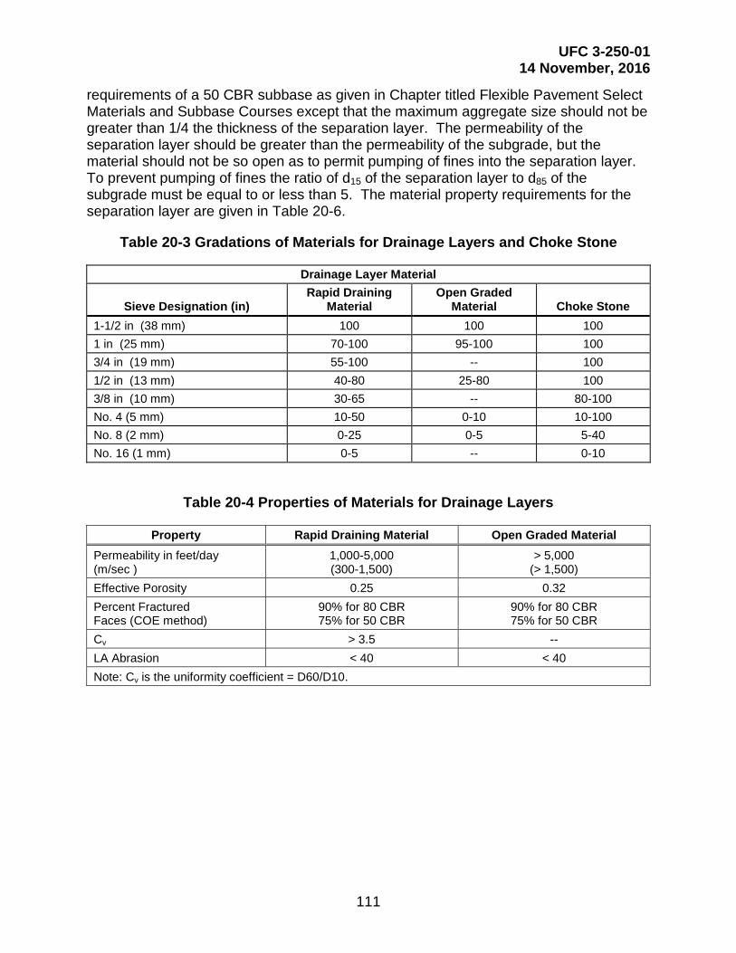
UFC 3-250-01 14 November, 2016
111
requirements of a 50 CBR subbase as given in Chapter titled Flexible Pavement Select Materials and Subbase Courses except that the maximum aggregate size should not be greater than 1/4 the thickness of the separation layer. The permeability of the separation layer should be greater than the permeability of the subgrade, but the material should not be so open as to permit pumping of fines into the separation layer. To prevent pumping of fines the ratio of d15 of the separation layer to d85 of the subgrade must be equal to or less than 5. The material property requirements for the separation layer are given in Table 20-6.
Table 20-3 Gradations of Materials for Drainage Layers and Choke Stone
Drainage Layer Material
Sieve Designation (in) Rapid Draining
Material Open Graded
Material Choke Stone 1-1/2 in (38 mm) 100 100 100 1 in (25 mm) 70-100 95-100 100 3/4 in (19 mm) 55-100 -- 100 1/2 in (13 mm) 40-80 25-80 100 3/8 in (10 mm) 30-65 -- 80-100 No. 4 (5 mm) 10-50 0-10 10-100 No. 8 (2 mm) 0-25 0-5 5-40 No. 16 (1 mm) 0-5 -- 0-10
Table 20-4 Properties of Materials for Drainage Layers
Property Rapid Draining Material Open Graded Material Permeability in feet/day (m/sec )
1,000-5,000 (300-1,500)
> 5,000 (> 1,500)
Effective Porosity 0.25 0.32 Percent Fractured Faces (COE method)
90% for 80 CBR 75% for 50 CBR
90% for 80 CBR 75% for 50 CBR
Cv > 3.5 -- LA Abrasion < 40 < 40 Note: Cv is the uniformity coefficient = D60/D10.

UFC 3-250-01 14 November, 2016
112
Table 20-5 Material Gradations for Drainage Layers
Sieve Size
Gradation No. 1 3/4 in (19 mm) max.
Gradation No. 2 1 in (25 mm) max.
Gradation No. 3 1-1/2 in ( 38 mm)max
Percent Passing Tolerance
Percent Passing Tolerance
Percent Passing Tolerance
1-1/2 in (38 mm) 100 -5
1 in (25 mm) 100 -5 79 ±8
3/4 in (19 mm) 100 -5 85 ±8 66 ±8
1/2 in (13 mm) 78 ±8 65 ±8 52 ±8
3/8 in (10 mm) 63 ±8 53 ±8 42 ±8
No. 4 (5 mm) 38 ±8 32 ±6 25 ±6
No. 8 (2 mm) 19 ±6 16 ±6 12 ±4
No. 16 (1 mm) 4 ±4 4 ±4 4 ±4
Table 20-6 Criteria for Granular Separation Layer
Maximum Aggregate Size Lesser of 2 in (50 mm)
or 1/4 of layer thickness Maximum CBR 50 Maximum Percent Passing No. 10 (2 mm ) 50 Maximum Percent Passing No. 200 (0.08 mm) 15 Maximum Liquid Limit 25 Maximum Plasticity Index 5
d15 of Separation Layer to d85 of Subgrade ≤ 5
20-3.6.2 Filter Fabric for Separation Layer.
Although filter fabric provides protection against pumping, it does not provide extra stability for compaction of the drainage layer. Therefore, fabric should be selected only when the subgrade provides adequate support for compaction of the drainage layer. The important characteristics of the fabric are strength for surviving construction and traffic loads, and AOS to prevent pumping of fines into the drainage layer. Filter fabric for separation must be a nonwoven needle punched fabric meeting the criteria given in Table 20-7.

UFC 3-250-01 14 November, 2016
113
Table 20-7 Criteria for Filter Fabric to be Used as a Separation Layer
Criteria ASTM Test Method 50 Percent or Less
Passing No. 200 Sieve AOS (mm) < 0.6 mm
Greater than No. 30 sieve D4751
Greater Than 50 Percent Passing No. 200 Sieve
AOS (mm) < 0.297 Greater than No. 50 sieve
D4751
Minimum Grab Strength in lb (kN) at 50% Elongation
0.8 (180) D4632/D4632M
Minimum Puncture Strength in lb (kN)
0.35 (80) D4833/D4833M
20-4 STABILIZATION OF DRAINAGE LAYER.
Stabilization of OGM is normally required for stability and strength, and to prevent degradation of the aggregate in handling and compaction. Stabilization may also be used when high quality crushed aggregate is not available and there may even be occasions when stabilization of RDM is necessary. Stabilization may be accomplished mechanically by use of a choke stone or by the use of a binder such as asphalt or Portland cement.
20-4.1 Choke Stone Stabilization.
A choke stone is a small size stone used to stabilize the surface of an OGM. The choke stone should be a hard, durable, crushed aggregate having 90 percent fractured faces. The ratio of d15 of the coarse aggregate to the d15 of the choke stone must be less than 5, and the ratio of the d50 of the coarse aggregate to d50 of the choke stone must be greater than 2. The gradation range for acceptable choke stone is given in Table 20-3.
20-4.2 Asphalt Stabilization.
Stabilize the drainage material with asphalt by using only enough asphalt to coat the aggregate. Take care to not fill the voids with excess asphalt. Asphalt grade used for stabilization should be AC20 or higher. For stabilization of OGM, 2 to 2-1/2 percent asphalt by weight should be sufficient to coat the aggregate. Higher rates of application may be necessary when stabilization of less open aggregate such as RDM is necessary.
20-4.3 Cement Stabilization.
As with asphalt stabilization, Portland cement stabilization should only use enough cement paste to coat the aggregate, and take care to not fill the voids with excess paste. The amount of Portland cement required should be about 2 bags/yd3 (170 kilograms per cubic meter) depending on the gradation of the aggregate. The water-cement ratio should be just sufficient to provide a paste which will adequately coat the aggregate.

UFC 3-250-01 14 November, 2016
114
20-5 COLLECTOR DRAINS.
20-5.1 Design Flow.
Provide collector drains to collect and transport water from under the pavement. For pavements having drainage layers, provide the drainage layers with a means for water to drain either with a collector or ditches. The collector system should have the capacity to handle the water from the drainage layer plus water from other sources. The water entering the collector system from the drainage layer is computed assuming the drainage layer is flowing full. Thus, the volume of water (Q) in cubic feet per day per foot (cubic millimeters per second per meter) of length of collector pipe (assuming the drainage layer is only on one side of the collector) would be
Equation 20-20 1000 in cubic mm per second per meterQ H i k= × × ×
or
Equation 20-21 in cubic ft per day per footQ H i k= × ×
where
H= thickness of the drainage layer, ft (mm)
i= slope of the drainage layer
k=permeability of the material in the drainage layer, ft/day (mm/sec)
If the collector system has water entering from both sides, the volume of water entering the collector would be twice that given by equation 20-20.
20-5.2 Design of Collector Drains.
20-5.2.1 Drain System Layout.
Normally, the collector drains are equally spaced along the shoulder of the pavement. The system consists of the drain pipe, flushing and observation risers, manholes, discharge laterals, filter fabric, and trench backfill. Since placement of subsurface drains under pavements may be a source of differential settlement or heave, this should be avoided when possible. The drainage system for large areas of pavement may require placement of subsurface drains under the pavement. For these cases the subsurface drains should be placed to avoid high traffic areas. In areas of extreme cold temperatures and heavy snow buildup laterals must be placed to reduce the probability of the laterals or outlets becoming clogged with ice or snow. Also in areas of extreme cold temperatures it may not be possible to place the collector drains below the depth of frost penetration therefore it is possible that the collector pipe may be filled with ice while thawing is occurring near the surface. For this case provisions must be made to drain the upper portion of the pavement either by day-lighting the drainage layer or providing special laterals to drain the drainage layer.

UFC 3-250-01 14 November, 2016
115
20-5.2.2 Collector Pipe.
The collector pipe may be perforated flexible, Acrylonitrile-Butadiene-Styrene, corrugated polyethylene (CPE) or smooth rigid polyvinyl chloride pipe (PVC). Pipe must conform to the appropriate AASHTO Specification. Most State Highway Agencies use either CPE or PVC. For CPE pipe, AASHTO specification M 252 “Corrugated Polyethylene Drainage Tubing” is suggested, while for PVC pipe, AASHTO Specification M 278, “Class PC 50 PVC Pipe,” is recommended. It is recommended that asphalt stabilized material not be used as backfill around pipe, but, if it is to be used, then the pipe should be PVC 90 degrees C electric plastic conduct, EPC40 or EPC80 conforming to the requirements of National Electrical Manufacturers Association Specification TC2. Geocomposite edge drains (strip drains) may be used in special situations but only with the approval of the Government Civil Engineer. Geocomposite edge drains should only be considered for pavements not having a drainage layer.
20-5.2.3 Pipe Size and Slopes.
The pipe must be sized, according to equations 20-22 or 20-23, to have a capacity sufficient to collect the peak flow from under the pavement. Equations 20-22 and 20-23 are Manning equations for computing the capacity of a full flowing circular drain. The equation for flow (Q) in cubic feet per second is:
Equation 20-22 ( )
⋅
⋅⋅= 2
132
4486.1 sdAn
Q
where
n = coefficient of roughness for the pipe A = area of the pipe, ft2 d = pipe diameter, ft s = slope of the pipe invert
For metric units the equation for flow in cubic meters per second is:
Equation 20-23 ( )
⋅
⋅⋅= 2
132
40.1 sdA
nQ
where
n and s are as defined in equation 20-22 A = pipe area, m2
d = pipe diameter, m
The coefficient of roughness for different pipe types can be obtained from Table 20-8 Except for long intercepting lines and extremely severe groundwater conditions, 6 in (150 mm) diameter drains should be satisfactory for most subsurface drainage installations. The minimum size pipe recommended for all collector drains is a 6 in (150 mm) diameter pipe. The recommended minimum slope for subdrains is 0.15 percent.

UFC 3-250-01 14 November, 2016
116
Table 20-8 Coefficient of Roughness for Different Types of Pipe
Type of Pipe Coefficient of Roughness, n Clay, concrete, smooth-wall plastic, and Asbestos-cement
0.013
Bituminous-coated, non-coated corrugated metal pipe or corrugated metal pipe
0.024
20-5.3 Placement of the Drainage Layer and Collector Drains.
20-5.3.1 Design.
In general the drainage layer is placed below the concrete surface in the case of rigid pavement and below the base course for a flexible pavement as illustrated in Figure C20-7, Figure C20-8, and Figure C20-9 (Appendix C). In most cases the trench for the collector drains should be constructed of sufficient width to provide 6 in (150 mm) clearance on each side of the pipe. The depth of the trench must be sufficient to provide a minimum 12 in (300 mm) from the top of the pavement subgrade to the center of the pipe plus 3 in (75 mm) clearance beneath the pipe. In frost areas extra care must be used in placing subsurface drains. For F3 and F4 subgrades a collector pipe will always be placed such that there will be positive drainage for the drainage layer and any NFS fill. If possible the drains should be placed below the depth of frost penetration. For many locations it will not be economically possible to place drains below the depth of frost penetration and therefore the drains and backfill will be subject to freezing. In areas where the depth of frost penetration is greater than 4 ft (1.2 m) below the bottom of the drainage layer, the top of the pipe need not be located deeper than 4 ft (1.2 m) below the bottom of the drainage layer. In frost areas where differential heave will cause pavement problems, the sides of the trench must be sloped not steeper than 1 vertical on 10 horizontal for the depth of frost penetration. At the edge of the pavement, where the pavement will not be subjected to traffic, the sides of the trench may be sloped at a slope of 1 vertical on 4 horizontal. The sloping of the trench sides is not required for the parts of the trench in NFS materials or for F1 or S1 soils unless the pavement over the trench is subjected to high speed traffic. The placement of collector drains under the interior portion of a pavement in frost areas is a special case where the collector drain is not directly connected to the drainage layer by an OGM or a RDM. This case is illustrated in Figure C20-7, Figure C20-8, and Figure C20-9 (Appendix C). The interior designs are based on the premise that NFS fill will have sufficient permeability to allow vertical drainage of the drainage layer into the collector pipes. Another premise is that the filter fabric will have sufficient area as not to impede the flow of water from the NFS fill to the collector pipe. The exception to the minimum requirement for the depth of the collector pipe below the surface of the subgrade is the interior case in a frost area for an F3 or F4 subgrade when the collection pipe is in above the depth of frost penetration. For this case the depth of the pipe below the surface of the subgrade is to be kept to a minimum.

UFC 3-250-01 14 November, 2016
117
20-5.3.2 Backfill.
Backfill the trench with a permeable material to rapidly convey water to the drainage pipe. The backfill material may be OGM, RDM, or other uniform graded aggregate. Place a minimum of 3 in (75 mm) of aggregate beneath the drainage pipe. Proper compaction or chemical stabilization of the backfill is necessary to prevent settlement of the fill. In placing the backfill, compact the backfill in lifts not exceeding 6 in (150 mm). When geocomposites are used in place of pipe, place the geocomposites against the material to be drained and thus the backfill is not expected to convey water. For this reason the backfill for the geocomposites will not require the high permeability required for the backfill around the pipe drains. However, since the backfill for the geocomposites will be against the side of the trench, the backfill should meet the requirements of a granular filter.
20-5.3.3 Geotextiles in the Trench.
Provide the trench with a geotextile filter fabric. Place the filter fabric to separate the permeable backfill of the trench from the subgrade or subbase materials. The filter fabric must not be placed so as to impede the flow of water from the drainage layer to the drain pipe. The filter fabric must also protect from the infiltration of fines from any surface layer. This is particularly important for drains placed outside the pavement area where surface water can enter the drain through a soil surface. The filter fabric for the trench must be a nonwoven needle punched fabric meeting the criteria given in Table 20-9.
Table 20-9 Criteria for Fabrics Used in Trench Construction
ASTM Test Method Criteria Soil With 50 Percent or Less Passing No. 200 Sieve
D 4751 AOS < Sieve No. 30 (0.6 mm)
Soil With Greater Than 50 Percent Passing No. 200 Sieve
D 4751 AOS < Sieve No. 50 (0.3 mm)
Minimum Grab Strength in lb (kN) at 50% Elongation
D4632/D4632M 130 (0.6)
Minimum Puncture Strength in lb (kN) D4833/D4833M 55 (0.25)
20-5.3.4 Trench Cap.
Cap edge drains placed outside of a paved area with a layer of low permeability material, such as an asphalt stabilized surface, to reduce the infiltration of surface water into the subsurface drainage system. If the area above the edge drain is to be sod surfaced, a filter layer will be required between the drain layer and sod.
UFC 3-250-01 14 November, 2016
118
20-5.4 Lateral Outlet Pipe.
20-5.4.1 Design.
The lateral outlet pipe provides both a means of getting water out of the edge drains, and for cleaning and inspecting the system as illustrated in Figure C20-10 and Figure C20-12 (Appendix C). Provide edge drains with lateral outlet pipes spaced at intervals 300 to 500 ft (90 to 150 m) along the edge drains and at the low point of all vertical curves. To facilitate drain cleanout, the outlet pipes should be placed at about a 45 degrees angle from the direction of flow in the collector drain. The lateral pipe should be a non-perforated solid-walled pipe and should be equipped with an outlet structure. A three percent slope from the edge drain to the outlet structure is recommended. To reduce outlet maintenance, outlet pipes should, where possible, be connected to existing storm drains or inlets. For lateral pipe flowing to a ditch, the invert of the outlet pipe should be a minimum of 6 in (150 mm) above the 2-year design flow in the ditch. To prevent piping, the trench for the outlet pipes must be backfilled with a material of low permeability, or provided with a cutoff wall or diaphragm. Dual outlets with large radius bend are recommended for maintenance considerations, as shown in Figure C20-11 (Appendix C). The dual outlet system allows sections of collector drains to be flushed out to clear any debris material blocking the free flow of water. Other recommended design details for drainage outlets are as follows:
• For pipe drains, use the same diameter pipe as the collector drains. For prefabricated geocomposite drains, 4 in (100 mm) to 6 in (150 mm) diameter pipe should provide adequate hydraulic capacity. The flow capacity of the outlets must be greater than that of the collector drains. In general, because of the greater slope provided for outlet pipes, the hydraulic capacity is not a problem.
• The discharge end of the outlet pipe should be placed at least 6 in (150 mm) above the 2 year design flow in the drainage ditch. The same requirement applies even if the outlet is discharging into storm drain inlets.
• In frost areas, give special attention to the placement of the outlet pipes such that they do not become clogged with ice or snow.
20-5.4.2 Outfall for Outlet Pipe.
The outfall for the outlet pipe should be provided with a headwall to protect the outlet pipe from damage, prevent slope erosion, and facilitate the location of outlet pipes. Place headwalls flush with the slope so that mowing operations are not impaired. Easily removed rodent screens should be installed at the pipe outlet. The headwall may be pre-cast or cast-in-place.
20-5.4.3 Reference Markers.
Although not a requirement, reference markers are recommended for the outlets to facilitate maintenance and observation. A simple flexible marker post or marking on the shoulder will suffice to mark the outlet.

UFC 3-250-01 14 November, 2016
119
20-5.5 Cross Drains.
Cross drains may be required at locations where flow in the drainage layer is blocked, on steep longitudinal grades where the water needs to be intercepted to prevent long drainage paths, or at the bottom of vertical curves. For example, cross drains may be required where pavements abut building foundations, at bridge approach slabs, or where drainage layers abut impermeable bases.
20-5.6 Manholes and Observation.
Manholes, observation basins, and risers are installed on subsurface drainage systems for access to the system to observe its operation and to flush or rod the pipe for cleaning. Manholes on subgrade pipe drains should be located at intervals of not over 1,000 ft (300 m) with one flushing riser located between manholes and at dead ends. Manholes should be provided at principal junction points of several drains.
UFC 3-250-01 14 November, 2016
120
CHAPTER 21 DESIGN OF AGGREGATE SURFACES
21-1 GENERAL.
The thickness design of aggregate surfaced roads and parking areas is similar to the design of flexible pavement as described in Chapter titled Flexible Pavement Design. This procedure involves selecting a vehicle mix or traffic, as explained in Chapter titled Vehicular Traffic, a subgrade CBR, and using unsurfaced design criteria contained within the PCASE software. The procedure determines total thickness of material to be placed above the subgrade, as well as its required strength in relation to the CBR value. A computer program is available for determining pavement thickness and compaction requirements and may be obtained as described in paragraph titled Pavement-Transportation Computer Assisted Structural Engineering.
21-2 ENTRANCES, EXITS, AND SEGMENTS.
Special consideration should be given to the design of approach roads, exit roads, and other heavily trafficked areas. Early failure or poor performance may be expected in these areas due to the channelized traffic. Since these areas will almost certainly be subjected to more frequent and heavier loads than the road, the design should be based on vehicular loads and passes usually used for primary road designs. In the case of large hardstands having multiple use and multiple entrances and exits, consideration should be given to partitioning and using different design sections. The immediate benefits that would accrue include economy through elimination of overdesign in some areas and better organization of vehicles and equipment.
21-3 THICKNESS CRITERIA (NON-FROST AREAS).
Refer to UFC 3-201-01 for minimum thickness requirements. Thickness requirements for aggregate surfaced roads and parking areas are determined using the PCASE software for a given soil strength and design vehicles and pass levels. Since roads and parking areas are usually designed for equivalent 18-kip (8,200-kg) axles, the design chart in Figure 21-1 is provided for convenience. The computed design thickness may be constructed of compacted granular fill for the total depth over the natural subgrade or in a layered system of granular fill (including subbases) and compacted subgrade for the same total depth. The layered section should be checked to ensure that an adequate thickness of material is used to protect the underlying layer and if it also meets the minimum surface CBR required. The granular fill may consist of base and subbase material provided the top 6 in (150 mm) meet the gradation requirements in Table 21-1.
21-4 FROST AREA CONSIDERATIONS.
In areas where frost effects have an impact on the design of pavements, additional considerations concerning thicknesses and required layers in the pavement structure must be addressed. The specific areas where frost has an impact on the design are discussed in the following paragraphs; however, a more detailed discussion of frost effects is presented in Chapter titled Seasonal Frost Conditions. For frost design purposes, soils have been divided into groups as shown in Table 19-2. Only the NFS

UFC 3-250-01 14 November, 2016
121
group is suitable for base course. NFS, S1, or S2 soils may be used for subbase course and any of the eight groups may be encountered as subgrade soils. Soils are listed in approximate order of decreasing bearing capability during periods of thaw.
Figure 21-1 Aggregate Surfaced Design Chart; 18-kip Axle (8,200-kg)
Table 21 1 Gradation for Aggregate Surface Courses
Sieve Designation No. 1 No. 2 No. 3 No. 4 1 in (25 mm) 100 100 100 100 3/8 in (10 mm) 5-85 60-100 --- --- No. 4 (5 mm ) 35-65 50-85 55-100 70-100 No. 10 (2 mm) 25-50 40-70 40-100 55-100 No. 40 (0.4 mm) 15-30 24-45 20-50 30-70 No. 200 (0.08 mm) 8-15 8-15 8-15 8-15 Note: The percent by weight finer than 0.02 mm must not exceed 3 percent.
UFC 3-250-01 14 November, 2016
122
21-4.1 Required Thickness.
Where frost susceptible subgrades are encountered, determine the section thickness required according to the reduced subgrade strength method. The reduced subgrade strength method requires the use of frost area soil support indexes listed in Table 19-3. Frost-area soil support indexes are used as if they were CBR values; the term CBR is not applied to them, however, because, being weighted average values for an annual cycle, their values cannot be determined by CBR tests.
21-4.2 Required Layers in Pavement Section.
When frost is a consideration, it is recommended that the pavement section consist of a series of layers that will ensure the stability of the system, particularly during thaw periods. The layered system in the aggregate fill may consist of a wearing surface of fine crushed stone, a coarse-graded base course, a well-graded subbase of sand or gravelly sand. To ensure the stability of the wearing surface, the width of the base course and subbase should exceed the final desired surface width by a minimum of 12 in (300 mm) on each side.
21-4.3 Wearing Surface.
The wearing surface contains fines to provide stability in the aggregate surface. The presence of fines helps the layer's compaction characteristics and helps to provide a relatively smooth riding surface.
21-4.4 Base Course.
The coarse-graded base course is important in providing drainage of the granular fill. It is also important that this material be NFS so that it retains its strength during spring thaw periods.
21-4.5 Subbase.
The well-graded sand subbase is used for additional bearing capacity over the frost susceptible subgrade and as a filter layer between the coarse-graded base course and the subgrade to prevent the migration of the subgrade into the voids in the coarser material during periods of reduced subgrade strength. The material must therefore meet standard filter criteria. The sand subbase must be either NFS or of low frost susceptibility (S1 or S2). The filter layer may or may not be necessary depending upon the type of subgrade material. If the subgrade consists principally of gravel or sand, the filter layer may not be necessary and may be replaced by additional base course if the gradation of the base course is such that it meets filter criteria. However, for finer grained soils, the filter layer will be necessary. If a geotextile is used, the sand subbase or filter layer may be omitted as the fabric will be placed directly on the subgrade and will act as a filter.

UFC 3-250-01 14 November, 2016
123
21-4.6 Compaction.
Compact the subgrade to provide uniformity of conditions and a firm working platform for placement and compaction of subbase. Compaction of subgrade does not change its frost-area soil support index because frost action causes the subgrade to revert to a weaker state. Hence, in frost areas, the compacted subgrade is not considered part of the layered system of the road which is comprised of only the wearing, base, and subbase courses.
21-4.7 Thickness of Base Course and Filter Layer.
Relative thicknesses of the base course and filter layer are variable and should be based on the required cover and economic conditions.
21-4.8 Alternate Design.
The reduced subgrade strength design procedure provides the thickness of soil required above a frost-susceptible subgrade to minimize frost heave. To provide a more economical design, a frost susceptible select material or subbase may be used as a part of the total thickness above the frost susceptible subgrade. However, the thickness above the select material or subbase must be determined by using the Frost Area Soil Support Index (FASSI) of the select or subbase material. Where frost-susceptible soils are used as select materials or subbases, they must meet the requirements of current specifications except that the restriction on the allowable percent finer than 0.02 mm is waived.
21-5 SURFACE COURSE REQUIREMENTS.
The requirements for the various materials to be used in the construction of aggregate surfaced roads and parking areas are dependent upon whether or not frost is a consideration in the design.
21-5.1 Non-Frost Areas.
The material used for gravel surfaced roads and parking areas should be sufficiently cohesive to resist abrasive action. It should have a liquid limit no greater than 35 and a plasticity index between 4 and 9. It should also be graded for maximum density and minimum volume of voids to enhance optimum moisture retention while resisting excessive water intrusion. The gradation, therefore, should consist of the optimum combination of coarse and fine aggregates that will ensure minimum void ratios and maximum density. Such a material will then exhibit cohesive strength as well as inter-granular shear strength. Recommended gradations are as shown in Table 21-1. If the fine fraction of the material does not meet plasticity characteristics, modification by addition of chemicals might be required. Chloride products can, in some cases, enhance moisture retention, and lime can be used to reduce excessive plasticity.

UFC 3-250-01 14 November, 2016
124
21-5.2 Frost Areas.
As previously stated, where frost is a consideration in the design of roads and parking areas, a layered system should be used. The percentage of fines should be restricted in all the layers to facilitate drainage and reduce the loss of stability and strength during thaw periods. Gradation numbers 3 and 4 shown in Table 21-1 should be used with caution since they may be unstable in a freeze-thaw environment.
21-6 COMPACTION REQUIREMENTS.
Compaction requirements for the subgrade and granular layers are expressed as a percent of maximum density as determined by ASTM D1557. For the granular layers, the material must be compacted to 100 percent of the maximum ASTM D698 density. Select materials and subgrades in fills must have densities equal to or greater than the values shown in Table 21-2, except that fills will be placed at no less than 95 percent compaction for cohesionless soils (PI < 5; LL < 25) or 90 percent compaction for cohesive soils (PI > 5; LL > 25). Subgrades in cuts must have densities equal to or greater than the values shown in Table 21-2. Subgrades occurring in cut sections must be either compacted from the surface to meet the densities shown in Table 21-2, removed and replaced before applying the requirements for fills, or covered with sufficient material so that the un-compacted subgrade is at a depth where the in-place densities are satisfactory. The depths shown in Table 21-2 are measured from the surface of the aggregate road and not the surface of the subgrade.
Table 21-2 Compaction Depth Requirements for Aggregate Surfaces
Equivalent Passes of an 18,000-lb (8,200-kg
) ESAL
Depth of Compaction or Percent Compaction Shown, in Cohesive Soils PI > 5, LL > 25
Cohesionless Soils PI ≤ 5, LL ≤ 25
100 95 90 85 80 100 95 90 85 < 15,500 2 4 6 7 9 4 7 10 13 < 67,500 3 5 7 9 11 5 8 12 16 < 295,000 3 5 8 10 13 5 10 14 18
< 1.3 million 3 6 9 12 14 6 11 16 21 < 5.7 million 4 7 10 13 16 7 12 18 23 < 25 million 4 7 11 15 18 7 14 20 26 < 112 million 4 8 12 16 20 8 15 22 29 < 500 million 5 9 13 18 22 9 17 24 31
< 2,200 million 5 10 15 20 25 10 19 28 35 ≥ 2,200 million 6 11 17 22 27 11 21 30 38
Symbols: < less than, > greater than; ≥ greater than or equal to. mm = inches x 25.4
21-7 DRAINAGE REQUIREMENTS.
Adequate surface drainage should be provided to minimize moisture damage. Expeditious removal of surface water reduces the potential for absorption and ensures
UFC 3-250-01 14 November, 2016
125
more consistent strength and reduced maintenance. Drainage, however, must be provided in a way to preclude damage to the aggregate surfaced road through erosion of fines or erosion of the entire surface layer. Also, care must be taken to ensure that the change in the overall drainage regime as a result of construction can be accommodated by the surrounding topography without damage to the environment or to the newly constructed road or airfield.
The surface geometry of a road should be designed so that drainage is provided at all points. Depending upon the surrounding terrain, surface drainage of the roadway can be achieved by a continual cross slope or by a series of two or more interconnecting cross slopes. The entire area should consist of one or more cross slopes having a gradient that meet the requirements of UFC 3-201-01. Judgment is required to arrange the cross slopes to remove water from the road at the nearest possible points while taking advantage of the natural surface geometry to the greatest extent possible.
Adequate drainage must be provided outside the road or airfield area to accommodate maximum possible drainage flow from the road. Ditches and culverts must be provided for this purpose. Culverts should be used sparingly and only in areas where adequate cover of granular fill is provided over the culvert. Additionally, adjacent areas and their drainage provisions should be evaluated to determine if rerouting is needed to prevent water from other areas flowing across the road or airfield.
Drainage is a critical factor in aggregate surface roads and parking area construction, and maintenance. Therefore, drainage should be considered before construction, and when necessary, serve as a basis for site selection.
21-7.1 Materials.
A wide selection of materials for dust control is available to the engineer. No one choice, however, can be singled out as being the most universally acceptable for all problem situations that may be encountered. However, several materials have been recommended for use and are discussed in UFC 3-260-17.
21-8 DESIGN EXAMPLES.
Appendix G contains two design examples of unsurfaced aggregate roads.

UFC 3-250-01 14 November, 2016
126
APPENDIX A REFERENCES
UNIFIED FACILITIES CRITERIA
http://www.wbdg.org/ccb/browse_cat.php?o=29&c=4
UFC 1-200-01 DoD Building Code (General Building Requirements)
UFC 3-201-01 - Civil Engineering
UFC 3-250-03 - Bituminous Pavements Standard Practice
UFC 3-250-04 - Standard Practice for Concrete Pavements
UFC 3-250-11 - Soil Stabilization for Pavements
UFC 3-260-02 - Flexible Pavement Design for Airfields
UFC 3-260-03 - Flexible Airfield Pavement Evaluation
UFC 3-260-17 - Dust Control for Roads, Airfields, and Adjacent Areas
AMERICAN ASSOCIATION OF STATE HIGHWAY AND TRANSPORTATION OFFICIALS (AASHTO)
AASHTO M 288 - Standard Specification for Geotextile Specification for Highway Applications
AASHTO MEPDG - Mechanistic-Empirical Pavement Design Guide: A Manual of Practice
AMERICAN SOCIETY FOR TESTING AND MATERIALS (ASTM), 1916 Race St., Philadelphia, PA 19103
ASTM C78/C78M - Standard Test Method for Flexural Strength of Concrete (Using Simple Beam with Third-Point Loading)
ASTM D560/560M/560M - Standard Test Methods for Freezing and Thawing Compacted Soil-Cement Mixtures
ASTM D698 - Standard Test Methods for Laboratory Compaction Characteristics of Soil Using Standard Effort (12 400 ft-lbf/ft3 (600 kN-m/m3))
ASTM D1557 - Standard Test Methods for Laboratory Compaction Characteristics of Soil Using Modified Effort (56,000 ft-lbf/ft3 (2,700 kN-m/m3))
ASTM D1883 - Standard Test Method for California Bearing Ratio (CBR) of Laboratory-Compacted Soils

UFC 3-250-01 14 November, 2016
127
ASTM D2487 - Standard Practice for Classification of Soils for Engineering Purposes (Unified Soil Classification System)
ASTM D4429 - Standard Test Method for CBR (California Bearing Ratio) of Soils in Place
ASTM D4632/D4632M - Standard Test Method for Grab Breaking Load and Elongation of Geotextiles
ASTM D4751 - Standard Test Method for Determining Apparent Opening Size of a Geotextile
ASTM D4833/D4833M - Standard Test Method for Index Puncture Resistance of Geomembranes and Related Products
ASTM D6951/D6951M - Standard Test Method for Use of the Dynamic Cone Penetrometer in Shallow Pavement Applications
UFC 3-250-01 14 November, 2016
128
APPENDIX B BEST PRACTICES
B-1 CONSTRUCTION OF THE DRAINAGE LAYER.
B-1.1 Experience.
Construction of drainage layers can present problems in handling, placement, and compaction. If the drainage material does not have adequate stability, major problems can develop in the placement of the surface layer above the drainage layer. Experience with highly permeable bases (drainage layers) both by the Corps of Engineers and various State Departments of Transportation indicates that pavements containing such layers can be constructed without undue difficulties provided due precautions are taken. The real key to successful construction of the drainage layers is the training and experience of the construction personnel. Before start of construction, instruct the construction personnel in the handling and placing of the drainage material. The placement of test strips is recommended for training of the construction personnel.
B-1.2 Placement of Drainage Layer.
Place the material for the drainage layer in a manner to prevent segregation and to obtain a layer of uniform thickness. The materials for the drainage layer require extra care in stockpiling and handling. Placement of the RDM and OGM is best accomplished using an asphalt concrete paver. To ensure good compaction, the maximum lift thickness should be no greater than 6 in (150 mm). If choke stone is used to stabilize the surface of OGM, place the choke stone after compaction of the final lift of OGM. Spread the choke stone in a thin layer no thicker than 1/2 in (10 mm) using a spreader box or asphalt paver. Work the choke stone into the surface of the OGM by the use of a vibratory roller and by wetting. The choke stone remaining on the surface should not migrate into the OGM by the action of water or traffic.
B-1.3 Compaction.
Compaction is a key element in the successful construction of the drainage layer. Compaction control normally used in pavement construction is not appropriate for materials such as the RDM and OGM. It is therefore, necessary to specify compaction techniques and level of effort instead of the properties of the end product. It is important to place the drainage material in relatively thin lifts of 6 in (150 mm) or less and to have a good firm foundation beneath the drainage material. The recommended method of determining the required compaction effort is to construct a test section and closely monitor the aggregate during compaction to determine when crushing of the aggregate appears excessive. Experience indicates that sufficient compaction can be obtained by six passes or less of a vibratory roller loaded at about 10 short tons (9 metric tons). Material not being stabilized with asphalt or cement should be kept moist during compaction. Asphalt stabilized material for drainage layers must be compacted at a somewhat lower temperature than a dense-graded asphalt material. In most cases, it will be necessary to allow an asphalt stabilized material to cool to less than 200 degrees F (93 degrees C) before beginning compaction.

UFC 3-250-01 14 November, 2016
129
B-1.4 Protection after Compaction.
After compaction, protect the drainage layer from contamination by fines from construction traffic and from flow of surface water. It is recommended to place the surface layer as soon as possible after placement of the drainage layer. Take precautions to protect the drainage layer from disturbance by construction equipment. Only tracked asphalt pavers should be allowed for paving over any RDM or OGM that has not been stabilized. Drivers should avoid rapid acceleration, hard braking, or sharp turning on the finished drainage layer. Although curing of cement stabilized drainage layers is not critical, efforts should be made to protect cement stabilized drainage layers at curing until the surface layer is placed.
B-1.5 Proof Rolling.
Proof rolling is not normally required, but for roads and parking areas that are to be subjected to traffic of heavy vehicles, it is good practice to require proof rolling. In particular, proof rolling the separation layer before placement of a drainage layer is recommended. For flexible pavements constructed for heavy material handling equipment, it is recommended that the proof rolling be accomplished using a rubber-tired roller load to provide a minimum tire force of 20,000 lb (90 kN) and inflated to at least 90 psi (620 kPa). A minimum of six coverages should be applied, where a coverage is the application of one tire print over each point in the surface of the designated area. For rigid pavements and other flexible pavements, proof rolling of the separation layer may be accomplished using the rubber-tired roller described above or by using a truck having tandem axles with either dual tires or super single tires. The truck should be loaded to provide 20,000 lb per axle. During proof rolling, action of the separation layer must be monitored for any sign of excessive movement or pumping that would indicate soft spots in the separation layer or the subgrade. Since the successful placement of the drainage layer depends on the stability of the separation layer, all weak spots must be removed and replaced with stable material. All replaced material must be proof rolled as specified above.
B-2 CONSTRUCTION: SEASONAL FROST CONDITIONS
B-2.1 CONTROL OF SUBGRADE AND BASE COURSE CONSTRUCTION.
Personnel responsible for field control of pavement construction in areas of seasonal freezing should give specific consideration to conditions and materials that could result in detrimental frost action. In frost areas, the contract plans and specifications should require the subgrade preparation work as indicated in paragraph titled Subgrade Requirements. They also should provide for special treatments such as removal of unsuitable materials encountered with sufficient information included to identify those materials and specify necessary corrective measures. However, construction operations quite often expose frost-susceptible conditions at isolated locations of a degree and character not revealed by even the most thorough subsurface exploration program. It is essential, therefore, that personnel assigned to field construction control be alert to recognize situations that require special treatment, whether or not anticipated

UFC 3-250-01 14 November, 2016
130
by the designing agency. They must also be aware of their responsibility for such recognition.
B-2.2 BASE COURSE CONSTRUCTION.
Where the available base course materials are well within the limiting percentages of fine material set forth above, the base course construction control should be in accordance with normal practice. In instances where the material selected for use in the top 50 percent of the total thickness of granular unbound base is borderline with respect to percentage of fine material passing the No. 200 sieve, or is of borderline frost susceptibility (usually materials having 1.5 to 3 percent of grains finer than 0.02 mm by weight), frequent gradation checks should be made to ensure that the materials meet the design criteria. If it is necessary for the contractor to be selective in the pit to obtain suitable materials, his operations should be inspected at the pit. It is more possible to reject unsuitable materials at the source when large volumes of base course are being placed. It may be desirable to stipulate thorough mixing at the pit and, if necessary, stockpiling, mixing in windrows, and spreading the material in compacted thin lifts to ensure uniformity. Finish surface stripping of pits should be enforced to prevent mixing of detrimental fine soil particles or lumps in the base material.
B-2.3 Gradation of Base Course Materials.
The gradation of base course materials after compaction should be determined often, particularly at the start of the job, to learn whether or not fines are being manufactured in the base under the passage of the compaction equipment. For base course materials exhibiting serious degradation characteristics, a test embankment may be needed to study the formation of fines by the proposed compaction process. Mixing of base course materials with frost susceptible subgrade soils should be avoided by making certain that the subgrade is properly graded and compacted before placement of base course, by ensuring that the first layer of base course filters out subgrade fines under traffic, and by eliminating the kneading caused by over compaction or insufficient thickness of the first layer of base course. Excessive rutting tends to cause mixing of subgrade and base materials. This can be greatly minimized by frequent rerouting of material-hauling equipment.
B-2.4 Visual Inspection.
After completion of each layer of base course, a careful visual inspection should be made before permitting additional material placement to ensure that areas with high percentages of fines are not present. In many instances these areas may be recognized both by examination of the materials and by observation of their action under compaction equipment, particularly when the materials are wet. The materials in any areas that do not meet the requirements of the specifications, which will reflect the requirements of this UFC, should be removed and replaced with suitable material. Do not use a leveling course of fine-grained material as a construction expedient to choke open-graded base courses, to establish fine grade, or to prevent overrun of concrete. Since the base course receives high stresses from traffic, this prohibition is essential to minimize weakening during the frost-melting period. Action should be taken to vary the

UFC 3-250-01 14 November, 2016
131
base course thickness so as to provide transition, when this is necessary, to avoid abrupt changes in pavement supporting conditions.
B-3 MAINTENANCE OF SUBSURFACE DRAINAGE SYSTEMS.
B-3.1 Monitoring Program.
Commitment to maintenance is as important as providing subsurface drainage systems. In fact, an improperly maintained drainage system can cause more damage to the pavement structure than if no drainage were provided at all. Poor maintenance leads to clogged or silted outlets and edge-drain pipes, missing rodent screens, excessive growth of vegetation blocking outlet pipes and openings on day-lighted bases, and growth of vegetation in side ditches. These problems can potentially cause backing up of water within the pavement system, thereby defeating the purpose of providing the drainage system. Therefore, inspections and maintenance of subsurface drainage systems should be made an integral part of the policy of any agency installing these systems. The inspection process comprises of two parts: (a) visual inspection and (b) video inspection.
B-3.1.1 Visual Inspection.
The visual inspection process includes the following items:
(i) Evaluation of external drainage-related features, including measurement of ditch depths and checking for crushed outlets, excessive vegetative growth, clogged and debris-filled day-lighted openings, condition of headwalls, presence of erosion, and missing rodent screens. This operation should be performed at least once a year.
(ii) Pavement condition evaluation to check for moisture-related pavement distresses such as pumping, faulting, and D-cracking in PCC pavements and fatigue cracking and AC stripping in AC pavements. This operation could be either a full-scale Pavement Condition Index (PCI) survey or a brief overview survey, depending on agency needs. The recommended frequency for this activity is once every 2 years.
B-3.1.2 Video Inspection.
Video inspections play a vital role in monitoring in-service drainage systems. The video inspection process can be used to check for clogged drains due to silting and intrusion of surrounding soil, as well as any problems with the drainage system, such as ruptured pipes and broken connections. Video inspections should be carried out on an as-needed basis whenever there is evidence of drainage-related problems. A video inspection system typically consists of a camera head, long flexible probe mounted on a frame for inserting the camera head into the pipe, and a data acquisition unit fitted with a video screen and a video recorder. This system can be used to detect and correct any construction problems before a project is accepted. The construction-related problems that are easily detected using the video equipment include crushed or

UFC 3-250-01 14 November, 2016
132
ruptured drainage pipes and improper connections between drainage pipes, as well as the connection between the outlet pipe and headwall.
B-3.2 Maintenance Guidelines.
B-3.2.1 Collector Drains and Outlets.
Flush the collector drains and outlets periodically with high-pressure water jets to loosen and remove any sediment that has built up within the system. The key to this operation is having the appropriate outlet details that facilitate the process, such as the dual headwall system shown in Figure C20-11 (Appendix C). Keep the area around the outlet pipes should be kept mowed to prevent any buildup of water. Repair or replace missing rodent screens and outlet markers, damaged pipes and headwalls need to be either repaired or replaced.
B-3.2.2 Day-lighted Systems.
Routine removal of roadside debris and vegetation clogging the day-lighted openings of a permeable or dense-graded base is very important for maintaining the functionality of these systems.
B-3.2.3 Drainage Ditches.
Mow the drainage ditches should be kept mowed to prevent excessive vegetative growth. Clean the bottom of the ditch of debris and silt deposited at the bottom of the ditch should be cleaned periodically to maintain the ditch line and to prevent water from backing up into the pavement system.
B-4 AGGREGATE ROADS
B-4.1 MAINTENANCE REQUIREMENTS.
The two primary causes of deterioration of aggregate surfaced roads and parking areas requiring frequent maintenance are environmental conditions and traffic. Rain or water flow wash fines from the aggregate surface and reduce cohesion, while traffic action causes displacement of surface materials. Maintenance should be performed at least every 6 months and more often if required. The frequency of maintenance will be high for the first few years of use but will decrease over time to a constant value. The majority of the maintenance will consist of periodic grading to remove the ruts and potholes that will inevitably be created by the environment and traffic and to replace fines. Occasionally during the lifetime of the road, the surface layer may have to be scarified, additional aggregate added to increase the thickness back to that originally required, and the wearing surface re-compacted to the specified density.
B-4.2 DUST CONTROL.
The primary objective of a dust palliative is to prevent soil particles from becoming airborne as a result of wind or traffic. Where dust palliatives are considered for traffic areas, they must withstand the abrasion of the wheels or tracks. An important factor

UFC 3-250-01 14 November, 2016
133
limiting the applicability of the dust palliative in traffic areas is the extent of surface rutting or abrasion that will occur under traffic. Some palliatives will tolerate deformations better than others, but normally ruts in excess of 1/2 in (13 mm) will result in the virtual destruction of any thin layer or shallow-depth penetration dust palliative treatment. The abrasive action of tank tracks may be too severe for use of some dust palliatives in a traffic area.

UFC 3-250-01 14 November, 2016
134
APPENDIX C GLOSSARY
C-1 ACRONYMS
AASHTO American Association of State Highway and Transportation Officials
AC Asphalt concrete
ADT Average Daily Traffic
AOS Apparent Opening Size
ASR Alkali-Silica Reaction
ASTM American Society for Testing and Materials
CBR California Bearing Ratio
CD Compact Disk
CPE Corrugated Polyethylene
DoD Department of Defense
DoT Department of Transportation
ESAL Equivalent Single Axle Load
FASSI Frost Area Soil Support Index
HEMTT Heavy Expanded Mobility Tactical Truck
HET Heavy Equipment Transport System
HMMWV High Mobility Multipurpose Wheeled Vehicle
LCF Lime-Cement-Fly Ash
LL Liquid Limit
NFS Non-Frost Susceptible
OGM Open Graded Material
PCASE Pavement-Transportation Computer Assisted Structural Engineering
PCC Portland Cement Concrete
PCI Pavement Condition Index
PI Plasticity Index
UFC 3-250-01 14 November, 2016
135
PVC Polyvinyl Chloride
RCCP Roller-Compacted Concrete Pavement
RDM Rapid Draining Material
UFC Unified Facilities Criteria
UFGS Unified Facility Guide Specifications
U.S. United States
USACE United States Army Corp of Engineering
USCS Unified Soil Classification System
C-2 DEFINITION OF TERMS
Apparent Opening Size (AOS): A measure of the opening size of a geotextile. AOS is the sieve number corresponding to the sieve size at which 95 percent of the single-size glass beads pass the geotextile (O95) when tested in accordance with ASTM D4751.
Average Daily Temperature: The average of the maximum and minimum temperatures for a day, or the average of several temperature readings taken at equal time intervals, generally hourly, during a day.
Base Course: Course containing all granular unbound, chemical- or bituminous-stabilized material between the pavement surfacing layer and the un-treated, chemical or bituminous stabilized subgrade.
Bound Base: Chemical-stabilized or bituminous-stabilized soil used in the base and subbase course, consisting of a mixture of mineral aggregates and soil with one or more commercial stabilizing additives. Bound base is characterized by a significant increase in compressive strength of the stabilized soil compared with the untreated soil. In frost areas bound base usually is placed directly beneath the pavement surfacing layer where its high strength and low deformability make possible a reduction in the required thickness of the pavement surfacing layer or the total thickness of pavement and base, or both. If the stabilizing additive is Portland cement, lime, or lime-cement-fly ash (LCF), the term bound base is applicable only if the mixture meets the requirements for cement-stabilized, lime-stabilized, or LCF-stabilized soil set forth within this UFC and in UFC 3-250-11.
Boulder Heave: The progressive upward migration of a large stone present within the frost zone in a frost-susceptible subgrade or base course. This is caused by adhesion of the stone to the frozen soil surrounding it while the frozen soil is undergoing frost heave. The stone will be kept from an equal, subsequent subsidence by soil that will have tumbled into the cavity formed beneath the stone. Boulders heaved toward the surface cause extreme pavement roughness and may eventually break through the surface, necessitating repair or reconstruction.
UFC 3-250-01 14 November, 2016
136
Coefficient of Permeability: A measure of the rate at which water passes through a unit area of material in a given amount of time under a unit hydraulic gradient.
Choke Stone: A small size stone used to stabilize the surface of an OGM. For a choke stone to be effective, the ratio of d15 of the coarse aggregate to the d15 of the choke stone must be less than 5, and the ratio of the d50 of the coarse aggregate to d50 of the choke stone must be greater than 2.
Composite Pavement: Existing pavement to be overlaid with rigid pavement is composed of an all-bituminous or flexible overlay on a rigid base pavement.
Cumulative Damage: The process by which each application of traffic load or each cycle of climatic change produces a certain irreversible damage to the pavement. The pavement deteriorates continuously under successive load applications or climatic cycles.
Degree-Days: The Fahrenheit degree-days for any given day equal to the difference between the average daily air temperature and 32 degrees Fahrenheit. The degree-days are minus when the average daily temperature is below 32 degrees Fahrenheit (freezing degree-days) and plus when above (thawing degree-days). Figure 19-1 shows sample curves obtained by plotting cumulative degree-days against time.
Design Freezing Index: The average air freezing index of the three coldest winters in the latest 30 year of record. If 30 years of record are not available, the air freezing index for the coldest winter in the latest 10 year period may be used. To avoid the necessity of adopting a new and only slightly different freezing index each year, the design freezing index at a site with continuing construction need not be changed more than once in 5 year unless the more recent temperature records indicate a significant change in thickness design requirements for frost. The design freezing index is illustrated in Figure 19-1.
Drainage Layer: A layer in the pavement structure that is specifically designed to allow rapid horizontal drainage of water from the pavement structure. The layer is also considered to be a structural component of the pavement and may serve as part of the base or subbase.
Effective Porosity: The effective porosity is defined as the ratio of the volume of voids that will drain under the influence of gravity to the total volume of a unit of aggregate. The difference between the porosity and the effective porosity is the amount of water that will be held by the aggregate. For materials such as the RDM and OGM, the water held by the aggregate will be small; thus, the difference between the porosity and effective porosity will be small (less than 10 percent). The effective porosity may be estimated by computing the porosity from the unit dry weight of the aggregate and the specific gravity of the solids which then should be reduced by 5 percent to allow for water retention on the aggregate.
Flexible Base Pavement: Existing pavement to be overlaid is composed of bituminous concrete, base, and subbase courses.

UFC 3-250-01 14 November, 2016
137
Flexible Overlay: A flexible pavement (either all-bituminous or bituminous with base course) used to strengthen an existing rigid or flexible pavement.
Freezing Index: The number of degree-days between the highest and lowest points on a curve of cumulative degree-days versus time for one freezing season. It is used as a measure of the combined duration and magnitude of below-freezing temperatures occurring during any given freezing season. The index determined for air temperature about 4.5 ft (1.4 m) above the ground is commonly designated as the air freezing index, while that determined for temperatures immediately below a surface is known as the surface freezing index.
Frost Action: The general term for freezing and thawing of moisture in materials and the resultant effects on these materials and on structures of which they are a part, or with which they are in contact.
Frost Boil: The breaking of a small section of a highway or airfield pavement under traffic with ejection of soft, semi-liquid subgrade soil. This is caused by the melting of the segregated ice formed by the frost action. This type of failure is limited to pavements with extreme deficiencies of total thickness of pavement and base over frost-susceptible subgrades, or pavements having a highly frost-susceptible base course.
Frost Heave: is the raising of a surface due to ice formation in the underlying soil.
Frost Melting Period: The interval of the year when the ice in the base, subbase, or subgrade materials is returning to a liquid state. It ends when all the ice in the ground has melted or when freezing is resumed. In some cases there may be only one frost-melting period, beginning during the general rise of air temperatures in the spring. However, one or more significant frost-melting intervals may occur during a winter season.
Frost Susceptible Soil: Soil in which significant detrimental ice segregation will occur when the requisite moisture and freezing conditions are present.
Geocomposite Edge Drain: A manufactured product using geotextiles, geogrids, geonets, or geomembranes in laminated or composite form, which can be used as an edge drain in place of trench-pipe construction.
Geotextile: A permeable textile used in geotechnical projects. For this UFC geotextile will refer to a nonwoven needle punch fabric that meets the requirements of the apparent opening size (AOS), grab strength and puncture strength specified for the particular application.
Granular Unbound Base Course: A base course containing no agents that impart higher cohesion by cementing action. Mixtures of granular soil with Portland cement, lime, or fly ash, in which the chemical agents have merely altered certain properties of the soil such as plasticity and gradation without imparting significant strength increase, also are classified as granular unbound base.

UFC 3-250-01 14 November, 2016
138
Ice Segmentation: The growth of ice as distinct lenses, layers, veins and masses in soils, commonly but not always oriented normal to the direction of heat loss.
Hardstand: An area for parking heavy vehicles, both wheeled and tracked, for significant periods of time. Hardstands are usually constructed of rigid concrete but may be constructed of compacted stone or compacted earth for short periods of time.
Hazen’s Effective Particle Diameter: The Hazen’s effective particle diameter is the particle size, in millimeters, which corresponds to 10 passing on the grain-size distribution curve. This parameter is one of the major parameters in determining the permeability of a soil.
Mean Daily Temperature: The mean of the average daily temperatures for a given day in each of several years.
Mean Freezing Index: The freezing index determined on the basis of mean temperatures. The period of record over which temperatures are averaged is usually a minimum of 10 year, preferably 30, and should be the latest available. The mean freezing index is illustrated in Figure 19-1.
Non-Frost Susceptible Materials: Cohesionless materials such as crushed rock, gravel, sand, slag, and cinders that do not experience significant detrimental ice segregation under normal freezing conditions. Non-Frost-susceptible materials also include cemented or otherwise stabilized materials that do not evidence detrimental ice segregation, loss of strength upon thawing, or freeze-thaw degradation.
Open Graded Material (OGM): A granular material having a very high permeability (greater than 5,000 ft/day (1,500 m/day)) which may be used for a drainage layer. Such a material will normally require stabilization for construction stability or for structural strength to serve as a base in a flexible pavement.
Open Storage Areas: Permanent exterior storage areas used by any type of wheeled vehicular traffic or having non-pneumatic loadings in excess of 200 psi (1.38 MPa), covered or uncovered, that are separate from the interior area of a building.
Overlay Pavement: A pavement constructed on an existing base pavement to increase load-carrying capacity or correct a surface defect.
Pavement Pumping: The ejection of water and soil through joints, cracks, and along edges of pavements caused by downward movements of sections of the pavement. This is actuated by the passage of heavy axle loads over the pavement after free water has accumulated beneath it.
Pavement Structure: Pavement structure is the combination of subbase, base, and surface layers constructed on a subgrade.
Period of Weakening: The interval of the year that starts at the beginning of a frost-melting period and ends when the subgrade strength has returned to normal summer values, or when the subgrade has again become frozen.

UFC 3-250-01 14 November, 2016
139
Permeable Base: An open-graded granular material with most of the fines removed (e.g., less than 10 percent passing the No. 16 sieve) to provide high permeability (1,000 ft/day or more) for use in a drainage layer.
Porosity: The amount of voids in a material, expressed as the ratio of the volume of voids to the total volume.
Rapid Draining Material (RDM): A granular material having a sufficiently high permeability 1,000 to 5,000 ft/day (300 to 1,500 m/day) to serve as a drainage layer and also having the stability to support construction equipment and the structural strength to serve as a base or a subbase.
Rigid Base Pavement: An existing rigid pavement is one on which an overlay is to be placed.
Rigid Overlay: A rigid pavement used to strengthen an existing flexible or rigid pavement.
Separation Layer: A layer provided directly beneath the drainage layer to prevent fines from infiltration or pumping into the drainage layer and to provide a working platform for construction and compaction of the drainage layer.
Stabilization: Stabilization refers to either mechanically or chemically stabilizing the drainage layer to increase the stability and strength to withstand construction traffic and design traffic. Mechanical stabilization is accomplished by the use of a choke stone and compaction. Chemical stabilization is accomplished by the use of either Portland cement or asphalt.
Subbase Course: The layer of supporting material between the base course and the subgrade.
Subsurface Drainage: The process of collecting and removing water from the pavement structure. Subsurface drainage systems are categorized into two functional categories: one for draining surface infiltration water, and the other for controlling groundwater.
C-3 TRI-SERVICE PAVEMENT DETAILS
The Pavements and Airfields Tri-Service Working Group has developed typical details for use during design. These details can be download at http://www.wbdg.org/ccb/browse_cat.php?o=29&c=248. Some of these details contain information that was provided in earlier versions of the superseded criteria documents.
When these details are changed, an updated version will be posted to the Whole Building Design Guide webpage. Updated details will be included in the document during the next change or revision. Refer to http://www.wbdg.org/ccb/browse_cat.php?o=29&c=248 for the most recent version.

UFC 3-250-01 14 November, 2016
140
Figure C14-1 Typical Layout of Joints at Intersection

UFC 3-250-01 14 November, 2016
141
Figure C14-3A Reinforced Rigid Pavement with Two Traffic Lanes

UFC 3-250-01 14 November, 2016
142
Figure C14-3B Reinforced Rigid Pavement with Two Traffic Lanes

UFC 3-250-01 14 November, 2016
143
Figure C14-4 Reinforced Rigid Pavement with Traffic and Parking Lanes
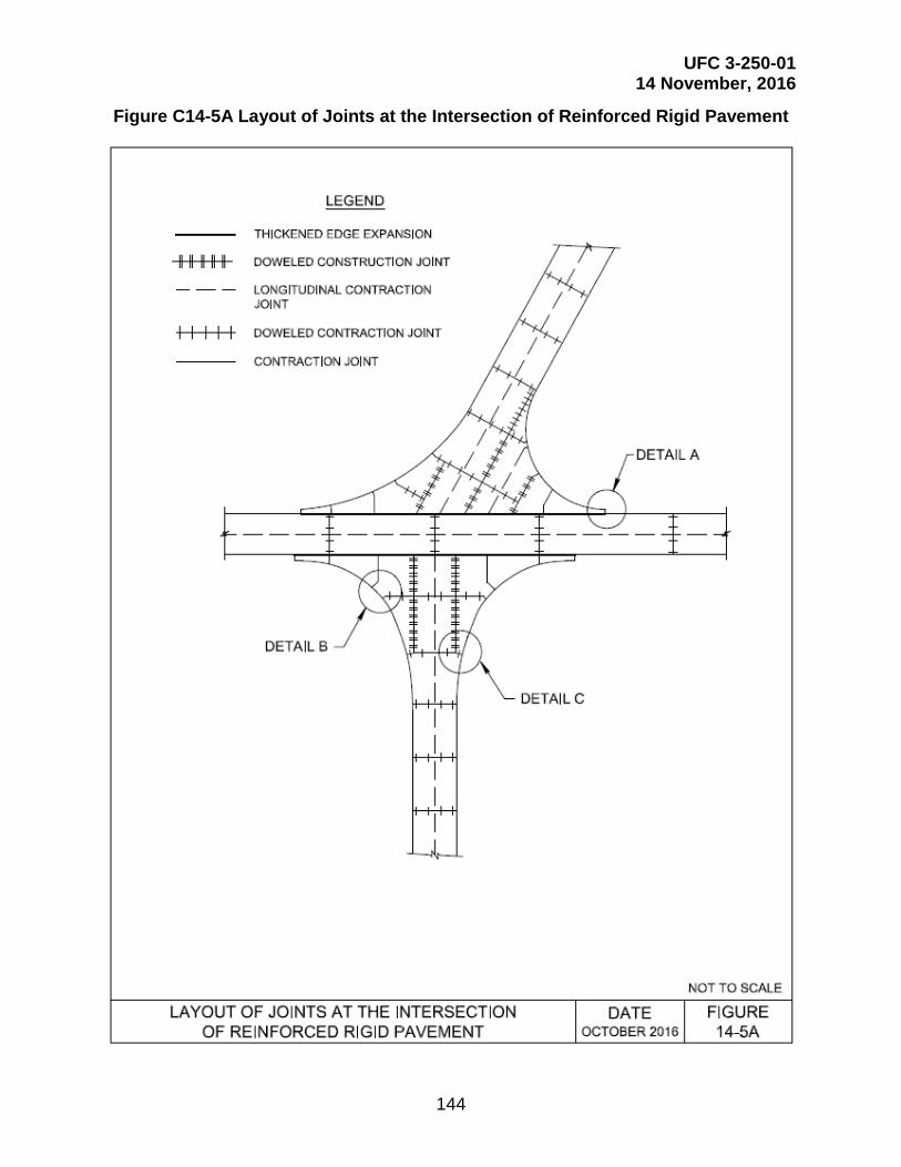
UFC 3-250-01 14 November, 2016
144
Figure C14-5A Layout of Joints at the Intersection of Reinforced Rigid Pavement
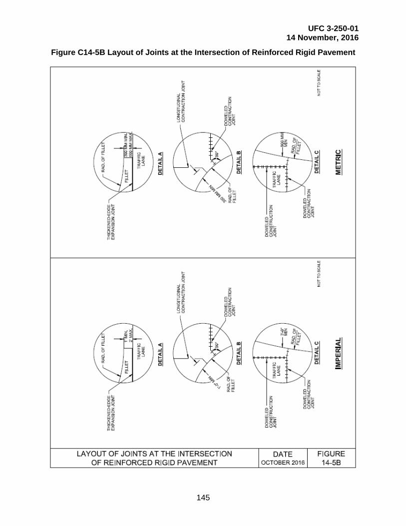
UFC 3-250-01 14 November, 2016
145
Figure C14-5B Layout of Joints at the Intersection of Reinforced Rigid Pavement

UFC 3-250-01 14 November, 2016
146
Figure C16-1A Plain Concrete Pavements
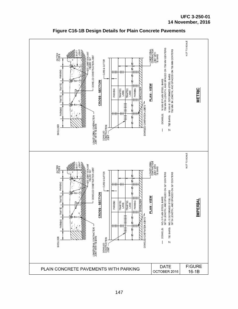
UFC 3-250-01 14 November, 2016
147
Figure C16-1B Design Details for Plain Concrete Pavements

UFC 3-250-01 14 November, 2016
148
Figure C16-2 Joint Layout for Vehicular Parking Areas
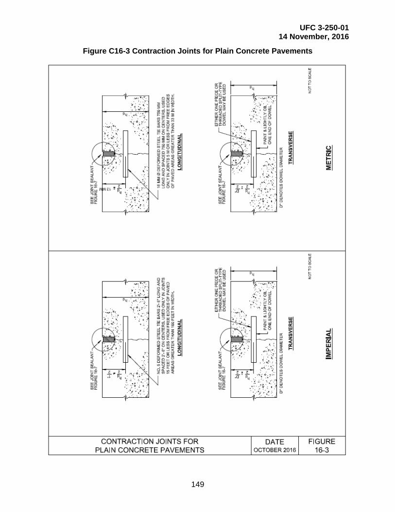
UFC 3-250-01 14 November, 2016
149
Figure C16-3 Contraction Joints for Plain Concrete Pavements

UFC 3-250-01 14 November, 2016
150
Figure C16-4A Construction Joints for Plain Concrete Pavements

UFC 3-250-01 14 November, 2016
151
Figure C16-4B Construction Joints for Plain Concrete Pavements

UFC 3-250-01 14 November, 2016
152
Figure C16-4C Construction Joints for Plain Concrete Pavements

UFC 3-250-01 14 November, 2016
153
Figure C16-4D Construction Joints for Plain Concrete Pavements
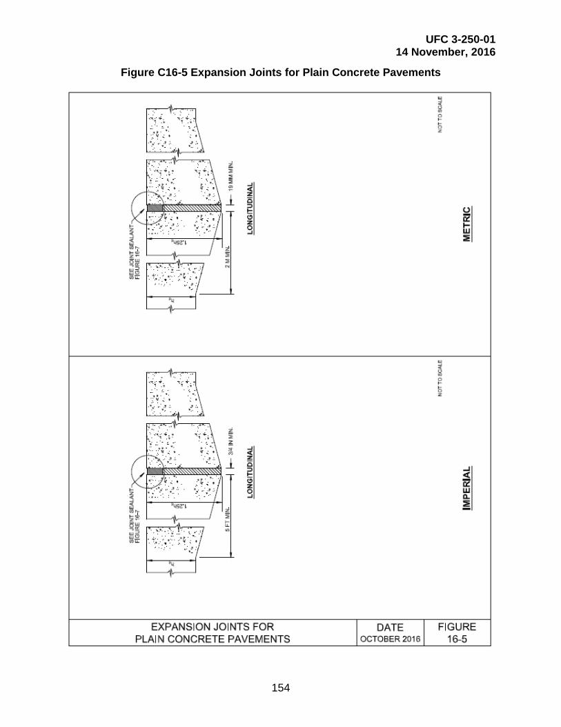
UFC 3-250-01 14 November, 2016
154
Figure C16-5 Expansion Joints for Plain Concrete Pavements
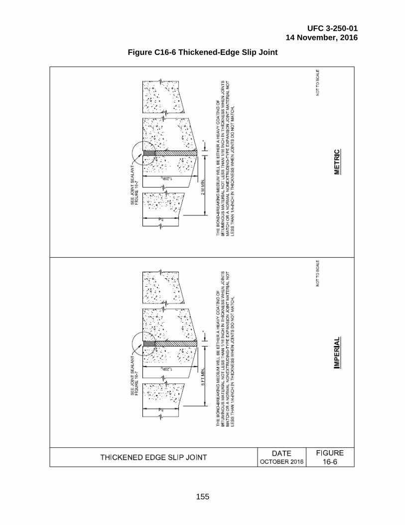
UFC 3-250-01 14 November, 2016
155
Figure C16-6 Thickened-Edge Slip Joint

UFC 3-250-01 14 November, 2016
156
Figure C16-7A Joint Sealants
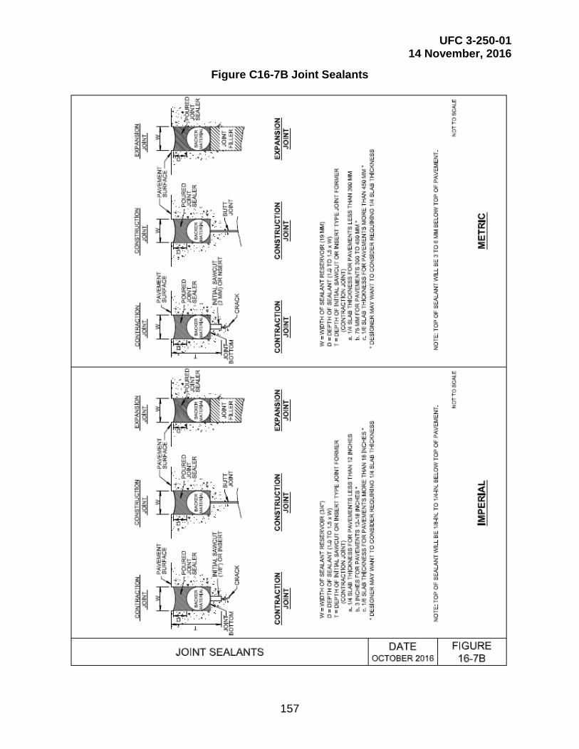
UFC 3-250-01 14 November, 2016
157
Figure C16-7B Joint Sealants

UFC 3-250-01 14 November, 2016
158
Figure C16-7C Joint Sealants

UFC 3-250-01 14 November, 2016
159
Figure C17-1 Contraction Joints for Reinforced Concrete Pavements

UFC 3-250-01 14 November, 2016
160
Figure C17-2A Construction Joints for Reinforced Concrete Pavements

UFC 3-250-01 14 November, 2016
161
Figure C17-2B Construction Joints for Reinforced Concrete Pavements

UFC 3-250-01 14 November, 2016
162
Figure C17-2C Construction Joints for Reinforced Concrete Pavements

UFC 3-250-01 14 November, 2016
163
Figure C17-2D Construction Joints for Reinforced Concrete Pavements
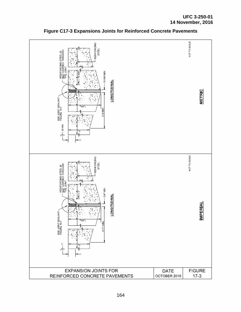
UFC 3-250-01 14 November, 2016
164
Figure C17-3 Expansions Joints for Reinforced Concrete Pavements
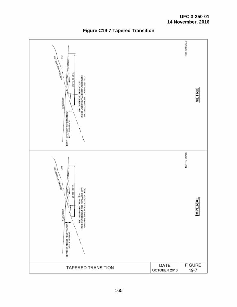
UFC 3-250-01 14 November, 2016
165
Figure C19-7 Tapered Transition

UFC 3-250-01 14 November, 2016
166
Figure C20-1 Collector Drain

UFC 3-250-01 14 November, 2016
167
Figure C20-2 Collector Drain to Intercept Seepage and Lower the Groundwater Table

UFC 3-250-01 14 November, 2016
168
Figure C20-3 Pavement Geometry for Computation of Time for Drainage

UFC 3-250-01 14 November, 2016
169
Figure C20-6 Plan View of Subsurface Drainage System

UFC 3-250-01 14 November, 2016
170
Figure C20-7A Typical Interior Subdrain for Rigid Pavement (Non-Frost Areas)

UFC 3-250-01 14 November, 2016
171
Figure C20-7B Typical Interior Subdrain for Rigid Pavement (Frost Areas, Depth of Frost > Depth to Pipe)

UFC 3-250-01 14 November, 2016
172
Figure C20-7C Typical Interior Subdrain for Rigid Pavement (Frost Areas, Depth of Frost < Depth to Pipe)

UFC 3-250-01 14 November, 2016
173
Figure C20-8A Typical Edge Subdrain for Rigid Pavement with Shoulder (Non-Frost Areas)

UFC 3-250-01 14 November, 2016
174
Figure C20-8B Typical Edge Subdrain for Rigid Pavement (Frost Areas)

UFC 3-250-01 14 November, 2016
175
Figure C20-9A Typical Interior Subdrain for Flexible Pavement (Non-Frost Areas)
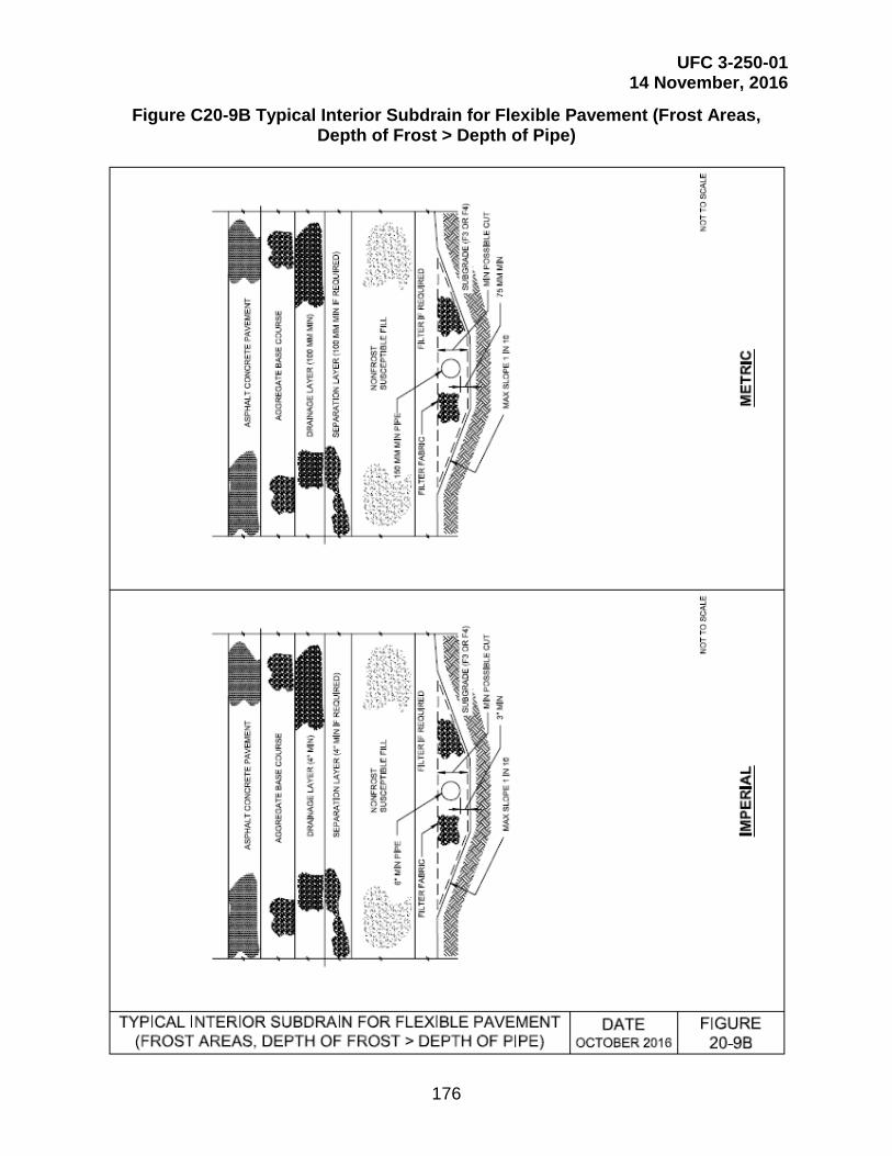
UFC 3-250-01 14 November, 2016
176
Figure C20-9B Typical Interior Subdrain for Flexible Pavement (Frost Areas, Depth of Frost > Depth of Pipe)
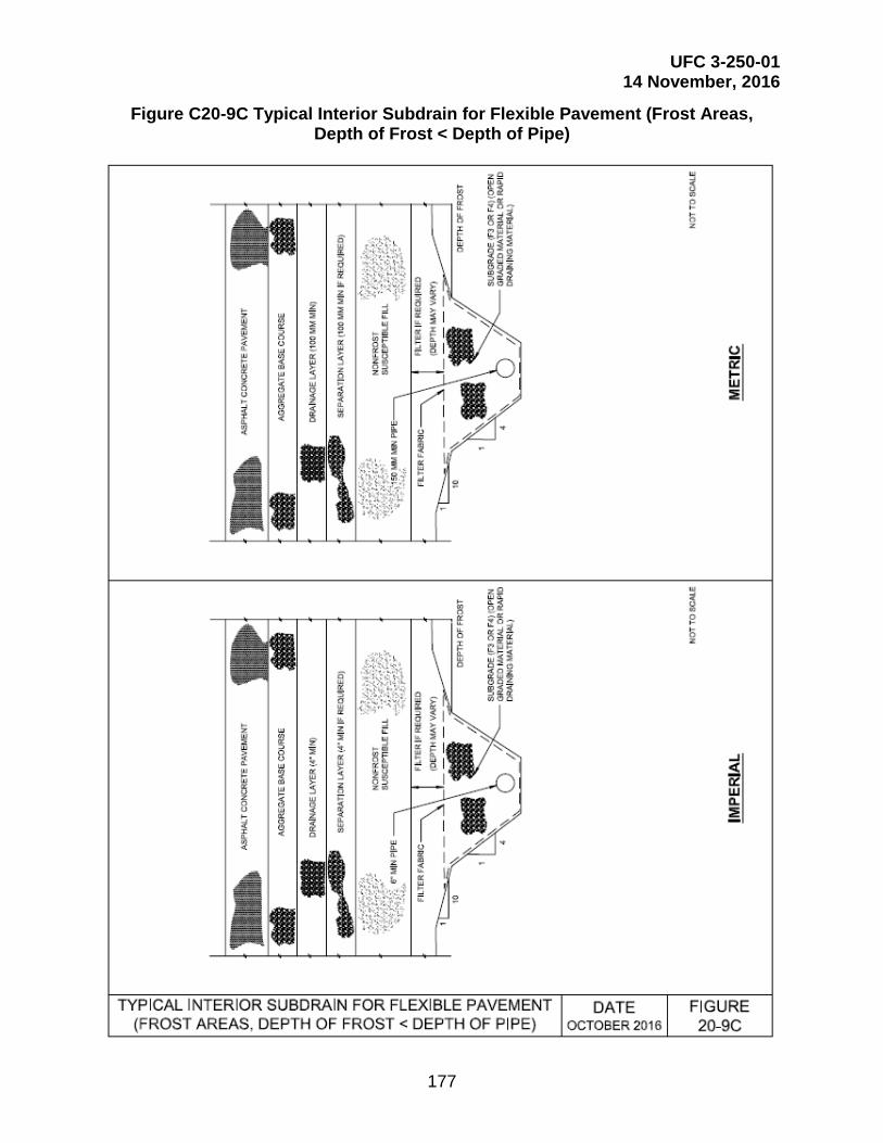
UFC 3-250-01 14 November, 2016
177
Figure C20-9C Typical Interior Subdrain for Flexible Pavement (Frost Areas, Depth of Frost < Depth of Pipe)

UFC 3-250-01 14 November, 2016
178
Figure C20-10A Typical Edge Subdrain for Flexible Pavement (Non-Frost Areas)

UFC 3-250-01 14 November, 2016
179
Figure C20-10B Typical Edge Subdrain for Flexible Pavement (Frost Areas)

UFC 3-250-01 14 November, 2016
180
Figure C20-11 Dual Outlet System Layout

UFC 3-250-01 14 November, 2016
181
Figure C20-12 Illustration of Large-Radius Bends Recommended for Drainage Outlet
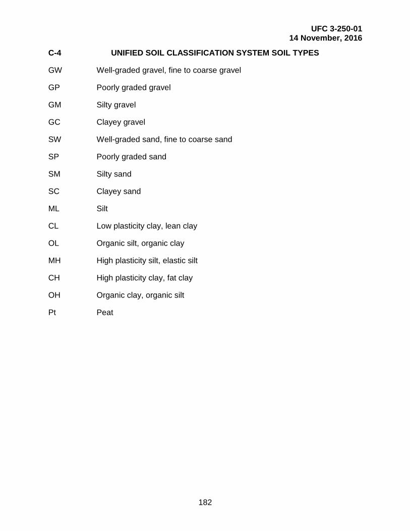
UFC 3-250-01 14 November, 2016
182
C-4 UNIFIED SOIL CLASSIFICATION SYSTEM SOIL TYPES
GW Well-graded gravel, fine to coarse gravel
GP Poorly graded gravel
GM Silty gravel
GC Clayey gravel
SW Well-graded sand, fine to coarse sand
SP Poorly graded sand
SM Silty sand
SC Clayey sand
ML Silt
CL Low plasticity clay, lean clay
OL Organic silt, organic clay
MH High plasticity silt, elastic silt
CH High plasticity clay, fat clay
OH Organic clay, organic silt
Pt Peat

UFC 3-250-01 14 November, 2016
183
C-5 UNITS OF MEASUREMENT AND UNIT CONVERSIONS
FROM ENGLISH CONVERSION FACTOR
TO METRIC Unit Definition Unit Definition
ft Foot x 0.305 m Meter in Inch x 25.4 mm Millimeters kip Kilopound x 454 kg Kilogram lb Pound x 0.454 kg Kilogram lb Pound x 0.00445 kN KiloNewton psi Pound per Square Inch x 0.00690 MPa MegaPascal F Fahrenheit (T°F-32)/1.8 C Celsius
FROM METRIC CONVERSION FACTOR
TO ENGLISH Unit Definition Unit Definition m Meter x 3.28 ft Foot
mm Millimeters x 0.0394 in Inch kg Kilogram x 0.0022 kip Kilopound kg Kilogram x 2.20 lb Pound kN KiloNewton x 224.7 lb Pound
MPa MegaPascal x 145 psi Pound per Square Inch C Celsius (1.8*T°C)+32 F Fahrenheit

UFC 3-250-01 14 November, 2016
184
APPENDIX D USE OF INSULATION MATERIALS IN PAVEMENTS
D-1 INSULATING MATERIALS AND INSULATED PAVEMENT SYSTEMS.
The only acceptable insulating material for use in roads is extruded polystyrene board stock. Results from laboratory and field tests have shown that extruded polystyrene does not absorb a significant volume of moisture and that it retains its thermal and mechanical properties for several years. The material is manufactured in board stock ranging from 1 in (25 mm) to 4 in (100 mm) thick. Approval from the Government Civil Engineer is required for use of insulating materials other than extruded polystyrene.
D-1.1 Synthetic Insulating Material.
The use of a synthetic insulating material within a pavement cross section is permissible with the written approval of the Government Civil Engineer. Experience has shown that surface icing may occur on insulated pavements at times when uninsulated pavements nearby are ice-free and vice versa. Surface icing creates possible hazards to fast-moving motor vehicles. Accordingly, in evaluating alternative pavement sections, the designer should select an insulated pavement only in special cases not sensitive to differential surface icing. Special attention should be given to the need for adequate transitions to pavements having greater or lesser protection against sub grade freezing.
D-1.2 Insulated Pavement System.
An insulated pavement system comprises conventional surfacing and base above an insulating material of suitable thickness to restrict or prevent the advance of subfreezing temperatures into a frost-susceptible subgrade. Unless the thickness of insulation and overlying layers is sufficient to stop subgrade freezing, additional layers of granular materials are placed between the insulation and the subgrade to contain a portion of the frost zone that extends below the insulation. In consideration of only the thermal efficiency of the insulated pavement system, 1 in (25 mm) of granular material placed below the insulating layer is much more effective than 1 in (25 mm) of the same material placed above the insulation. Hence, under the design procedure outlined below, the thickness of the pavement and base above the insulation is determined as the minimum that will meet structural requirements for adequate cover over the relatively weak insulating material. The determination of the thickness of insulation and of additional granular material is predicated on the placement of the latter beneath the insulation.
D-2 DETERMINATION OF THICKNESS OF COVER ABOVE INSULATION.
On a number of insulated pavements in the civilian sector, the thickness of material above the insulation has been established to limit the vertical stress on the insulation caused by dead loads and wheel loads to not more than one-third of the compressive strength of the insulating material. The Boussinesq equation should be used for this determination. If a major project incorporating insulation is planned, advice and assistance in regard to the structural analysis should be sought from the Government Civil Engineer.

UFC 3-250-01 14 November, 2016
185
D-3 DESIGN OF INSULATED PAVEMENT TO PREVENT SUBGRADE FREEZING.
Once the thickness of pavement and base above the insulation has been determined, it should be ascertained whether a reasonable thickness of insulation will keep subfreezing temperatures from penetrating through the insulation. Calculations for this purpose make use of the design air and surface freezing indexes and the mean annual soil temperature at the site. If the latter is unknown, it may be approximated by adding 7 degrees Fahrenheit to the mean annual air temperature. For paved surfaces kept free from snow and ice, an n-factor of 0.75 should be used. For calculating the required thickness of insulation, the design surface freezing index and the mean annual soil temperature are used with Figure D-1 to determine the surface temperature amplitude A. The initial temperature differential Vo is obtained by subtracting 32 degrees Fahrenheit from the mean annual soil temperature, or it also may be read directly from Figure D-1. The ratio Vo/A is then determined. Figure D-2 is then entered with the adopted thickness of pavement and base to obtain the thickness of extruded polystyrene insulation needed to prevent subgrade freezing beneath the insulation. If the required thickness is less than about 2 (50 mm) to 3 in (75 mm), it will usually be economical to adopt for design the thickness given by Figure D-2, and to place the insulation directly on the subgrade. If more than about 2 (50 mm) to 3 in (75 mm) of insulation is required to prevent subgrade freezing, it usually will be economical to use a lesser thickness of insulation, underlain by subbase material (S1 or S2). Alternative combinations of thicknesses of extruded polystyrene insulation and granular material base and subbase to contain completely the zone of freezing can be determined from Figure D-3, which shows the total depth of frost for various freezing indexes, thicknesses of extruded polystyrene insulation, and base courses. The thickness of subbase needed to contain the zone of freezing is the total depth of frost penetration less the total thickness of pavement, base, and insulation.
D-4 DESIGN OF INSULATED PAVEMENT FOR LIMITED SUB GRADE FREEZING.
It may be economically advantageous to permit some penetration of frost into the subgrade. Accordingly, the total depth of frost penetration given by Figure D-3 may be taken as the value in Figure 19-4, and a new combined thickness b of base, insulation, and subbase is determined that permits limited frost penetration, into the subgrade. The thickness of subbase needed beneath the insulation is obtained by subtracting the previously established thicknesses of base, determined from structural requirements, and of insulation, determined from Figure D-3. Not less than 4 in (100 mm) of subbase material meeting the requirements of Chapter titled Seasonal Frost Conditions should be placed between the insulation and the subgrade. If less than 4 in (100 mm) of subbase material is necessary, consideration should be given to decreasing the insulation thickness and repeating the process outlined above.
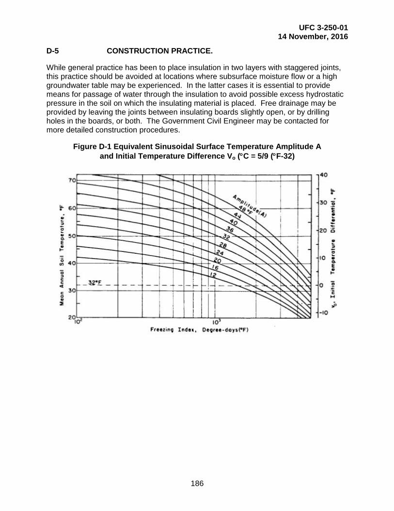
UFC 3-250-01 14 November, 2016
186
D-5 CONSTRUCTION PRACTICE.
While general practice has been to place insulation in two layers with staggered joints, this practice should be avoided at locations where subsurface moisture flow or a high groundwater table may be experienced. In the latter cases it is essential to provide means for passage of water through the insulation to avoid possible excess hydrostatic pressure in the soil on which the insulating material is placed. Free drainage may be provided by leaving the joints between insulating boards slightly open, or by drilling holes in the boards, or both. The Government Civil Engineer may be contacted for more detailed construction procedures.
Figure D-1 Equivalent Sinusoidal Surface Temperature Amplitude A and Initial Temperature Difference Vo (°C = 5/9 (°F-32)

UFC 3-250-01 14 November, 2016
187
Figure D-2 Thickness of Extruded Polystyrene Insulation to Prevent Subgrade Freezing (millimeter = 25.4 × inches, meter = 3.28 ft)
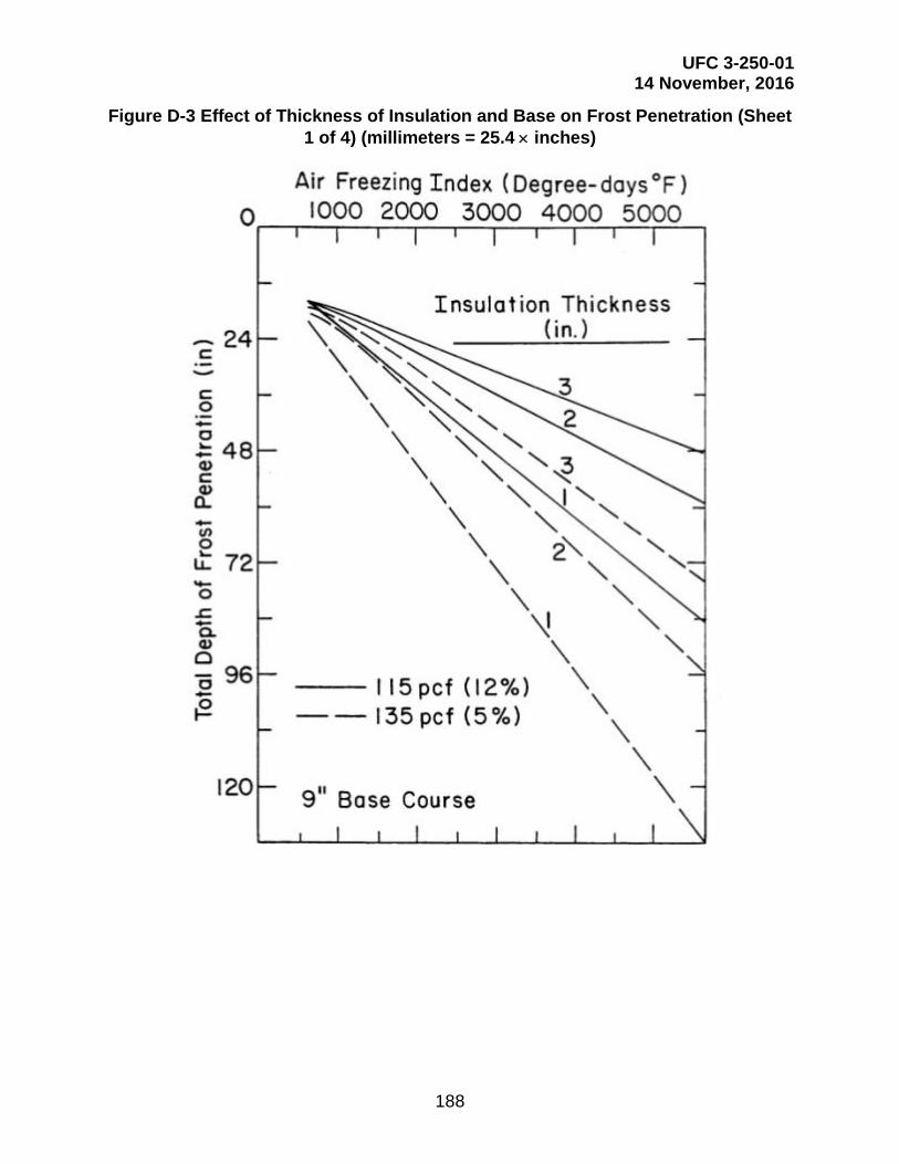
UFC 3-250-01 14 November, 2016
188
Figure D-3 Effect of Thickness of Insulation and Base on Frost Penetration (Sheet 1 of 4) (millimeters = 25.4 × inches)

UFC 3-250-01 14 November, 2016
189
Figure D-3 Effect of Thickness of Insulation and Base on Frost Penetration (Sheet 2 of 4) (millimeters = 25.4 × inches) (kg/m3 = 16 × pcf)

UFC 3-250-01 14 November, 2016
190
Figure D-3 Effect of Thickness of Insulation and Base on Frost Penetration (Sheet 3 of 4) (millimeters = 25.4 × inches) (kg/m3 = 16 × pcf)
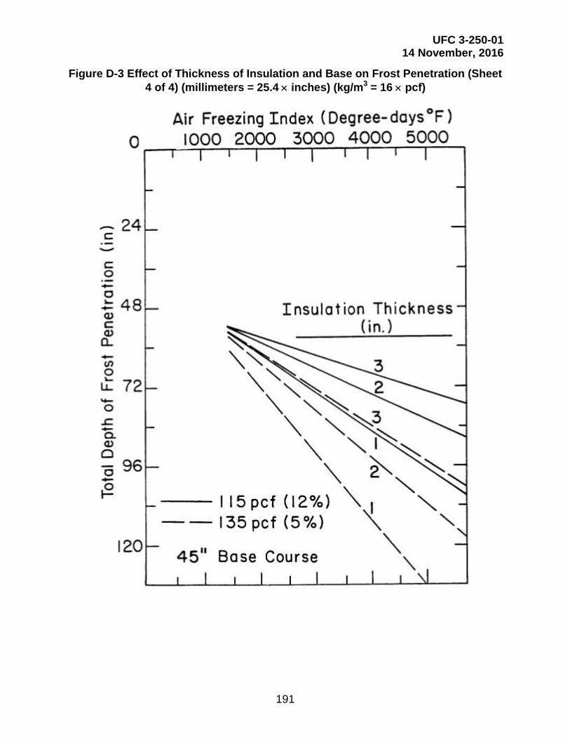
UFC 3-250-01 14 November, 2016
191
Figure D-3 Effect of Thickness of Insulation and Base on Frost Penetration (Sheet 4 of 4) (millimeters = 25.4 × inches) (kg/m3 = 16 × pcf)

UFC 3-250-01 14 November, 2016
192
APPENDIX E FLEXIBLE PAVEMENT DESIGN CURVES
Figure E-1 Single Axle, Dual-Tire Load Flexible Pavement Design Curve
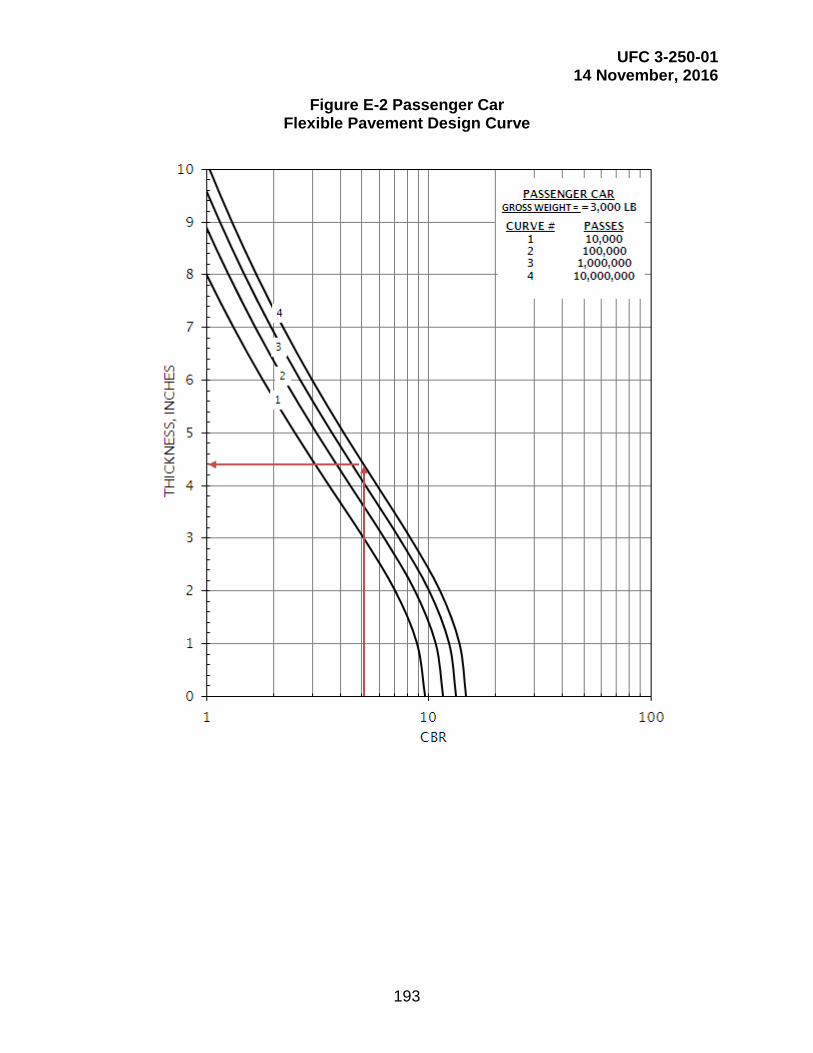
UFC 3-250-01 14 November, 2016
193
Figure E-2 Passenger Car Flexible Pavement Design Curve
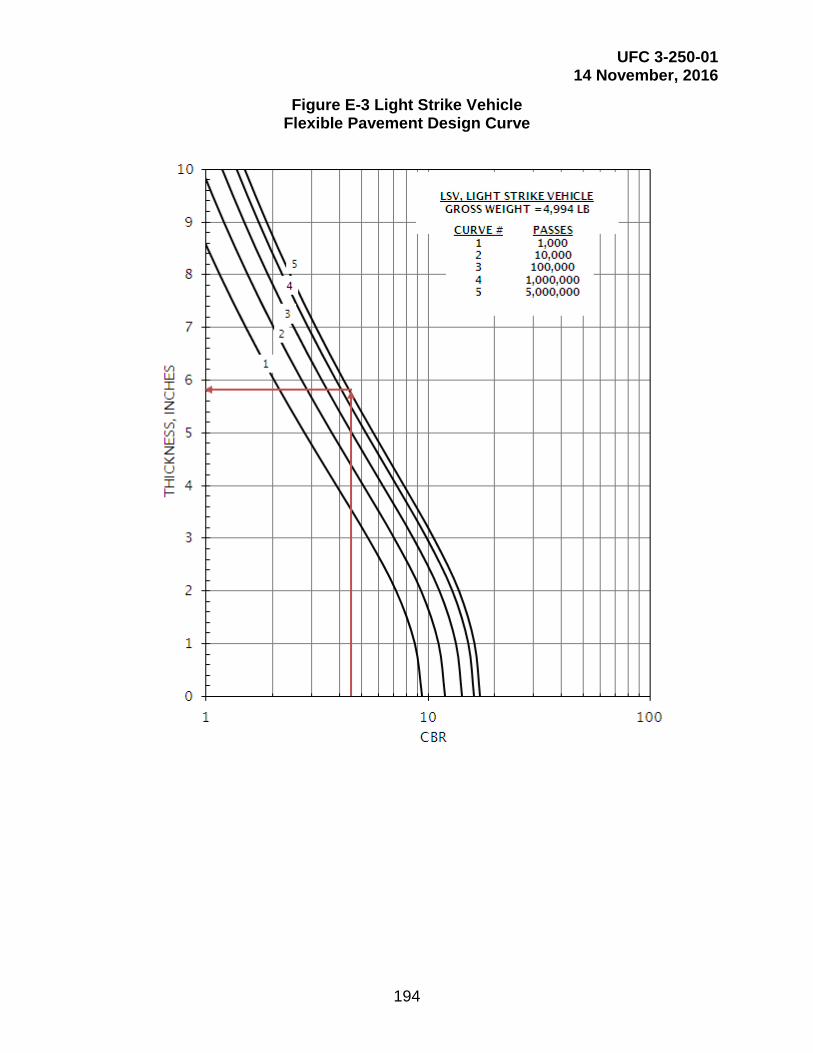
UFC 3-250-01 14 November, 2016
194
Figure E-3 Light Strike Vehicle Flexible Pavement Design Curve

UFC 3-250-01 14 November, 2016
195
Figure E-4 M1A1 Main Tank Flexible Pavement Design Curve

UFC 3-250-01 14 November, 2016
196
Figure E-5 M1A2 Main Tank Flexible Pavement Design Curve

UFC 3-250-01 14 November, 2016
197
Figure E-6 M2A3 Bradley Vehicle Tracked Flexible Pavement Design Curve

UFC 3-250-01 14 November, 2016
198
Figure E-7 M35A2 2.5-Ton Cargo Truck 6x6 Flexible Pavement Design Curve

UFC 3-250-01 14 November, 2016
199
Figure E-8 M60A3 Main Tank Flexible Pavement Design Curve

UFC 3-250-01 14 November, 2016
200
Figure E-9 M109A6, 155 Howitzer Tracked Flexible Pavement Design Curve

UFC 3-250-01 14 November, 2016
201
Figure E-10 M113A1 Armored Carrier Tracked Flexible Pavement Design Curve

UFC 3-250-01 14 November, 2016
202
Figure E-11 M923 5-Ton Cargo Truck 6x6 Flexible Pavement Design Curve
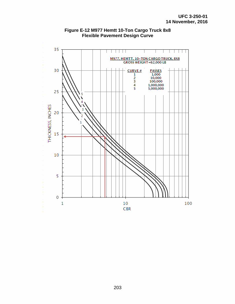
UFC 3-250-01 14 November, 2016
203
Figure E-12 M977 Hemtt 10-Ton Cargo Truck 8x8 Flexible Pavement Design Curve
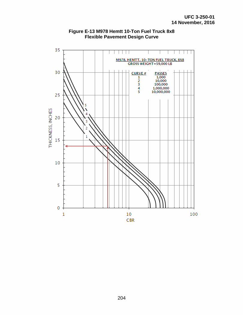
UFC 3-250-01 14 November, 2016
204
Figure E-13 M978 Hemtt 10-Ton Fuel Truck 8x8 Flexible Pavement Design Curve
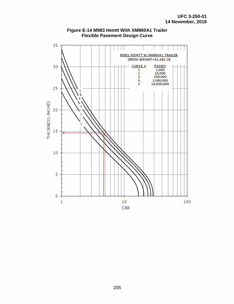
UFC 3-250-01 14 November, 2016
205
Figure E-14 M983 Hemtt With XM860A1 Trailer Flexible Pavement Design Curve

UFC 3-250-01 14 November, 2016
206
Figure E-15 M998 HMMWV 1.25-Ton Carrier Flexible Pavement Design Curve
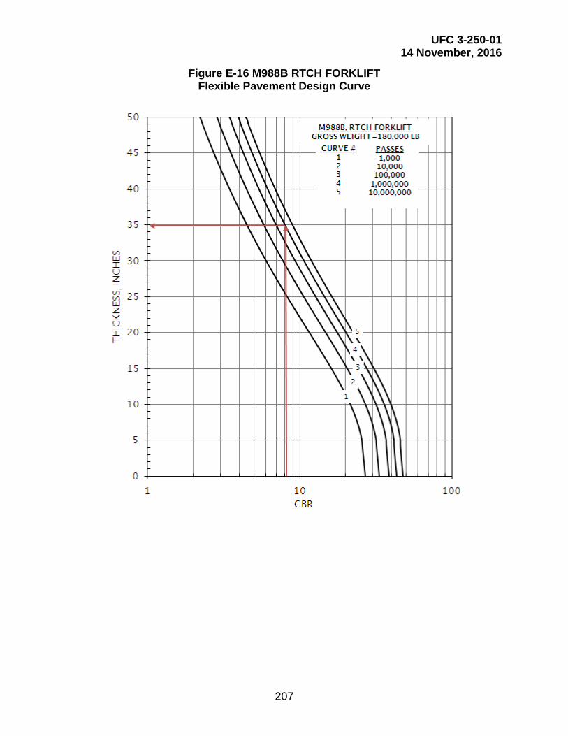
UFC 3-250-01 14 November, 2016
207
Figure E-16 M988B RTCH FORKLIFT Flexible Pavement Design Curve

UFC 3-250-01 14 November, 2016
208
Figure E-17 M1070 HET Tractor W/M1000 TRL W/M1A1 Tank Flexible Pavement Design Curve

UFC 3-250-01 14 November, 2016
209
Figure E-18 M1074 Load System w/Crane w/M1076 Trailer Flexible Pavement Design Curve
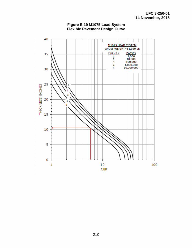
UFC 3-250-01 14 November, 2016
210
Figure E-19 M1075 Load System Flexible Pavement Design Curve

UFC 3-250-01 14 November, 2016
211
Figure E-20 M1075 Load System w/M1076 Trailer Flexible Pavement Design Curve
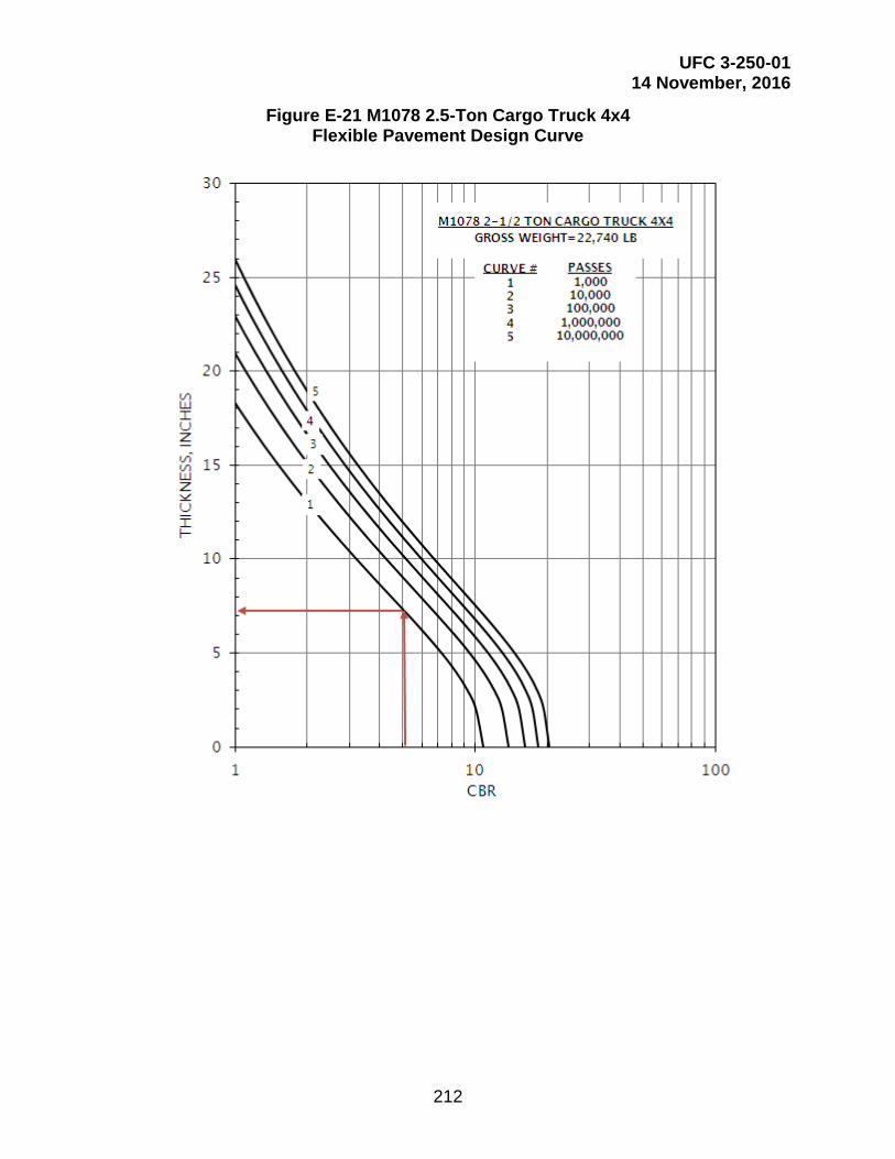
UFC 3-250-01 14 November, 2016
212
Figure E-21 M1078 2.5-Ton Cargo Truck 4x4 Flexible Pavement Design Curve
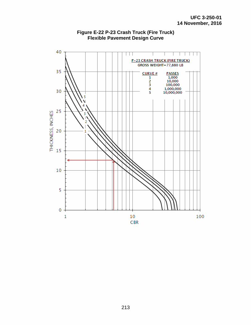
UFC 3-250-01 14 November, 2016
213
Figure E-22 P-23 Crash Truck (Fire Truck) Flexible Pavement Design Curve

UFC 3-250-01 14 November, 2016
214
Figure E-23 R-11 Refueler Flexible Pavement Design Curve

UFC 3-250-01 14 November, 2016
215
Figure E-24 Truck, Small Pickup, or SUV Flexible Pavement Design Curve

UFC 3-250-01 14 November, 2016
216
Figure E-25 Truck, Large Pickup, or SUV Flexible Pavement Design Curve
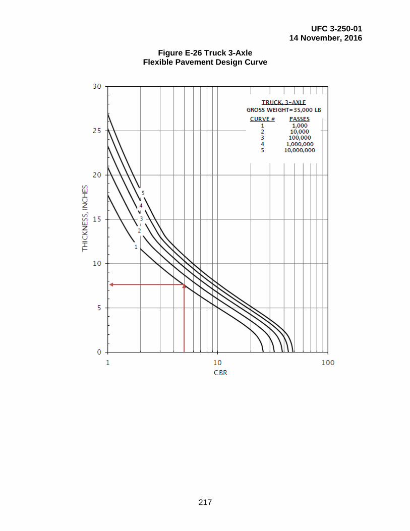
UFC 3-250-01 14 November, 2016
217
Figure E-26 Truck 3-Axle Flexible Pavement Design Curve

UFC 3-250-01 14 November, 2016
218
Figure E-27 Truck 4-Axle Flexible Pavement Design Curve
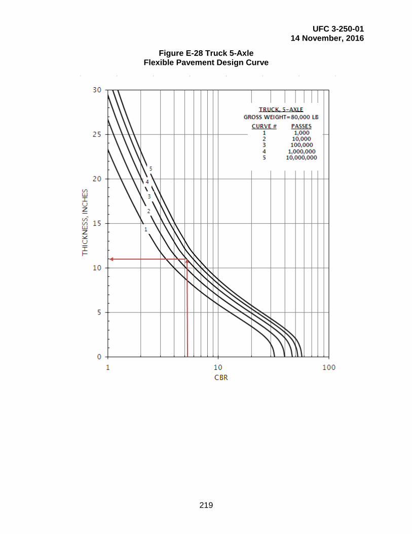
UFC 3-250-01 14 November, 2016
219
Figure E-28 Truck 5-Axle Flexible Pavement Design Curve

UFC 3-250-01 14 November, 2016
220
Figure E-29 Truck 2-Axle, 6-Tire Flexible Pavement Design Curve

UFC 3-250-01 14 November, 2016
221
Figure E-30 TYC-850L Container Truck Flexible Pavement Design Curve

UFC 3-250-01 14 November, 2016
222
Figure E-31 75BFMII Mobile Crane Flexible Pavement Design Curve

UFC 3-250-01 14 November, 2016
223
This Page Intentionally Left Blank
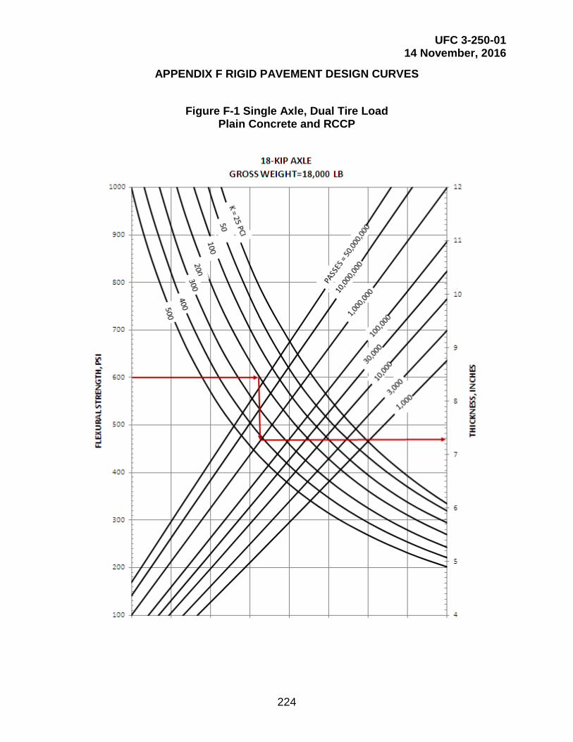
UFC 3-250-01 14 November, 2016
224
APPENDIX F RIGID PAVEMENT DESIGN CURVES
Figure F-1 Single Axle, Dual Tire Load
Plain Concrete and RCCP
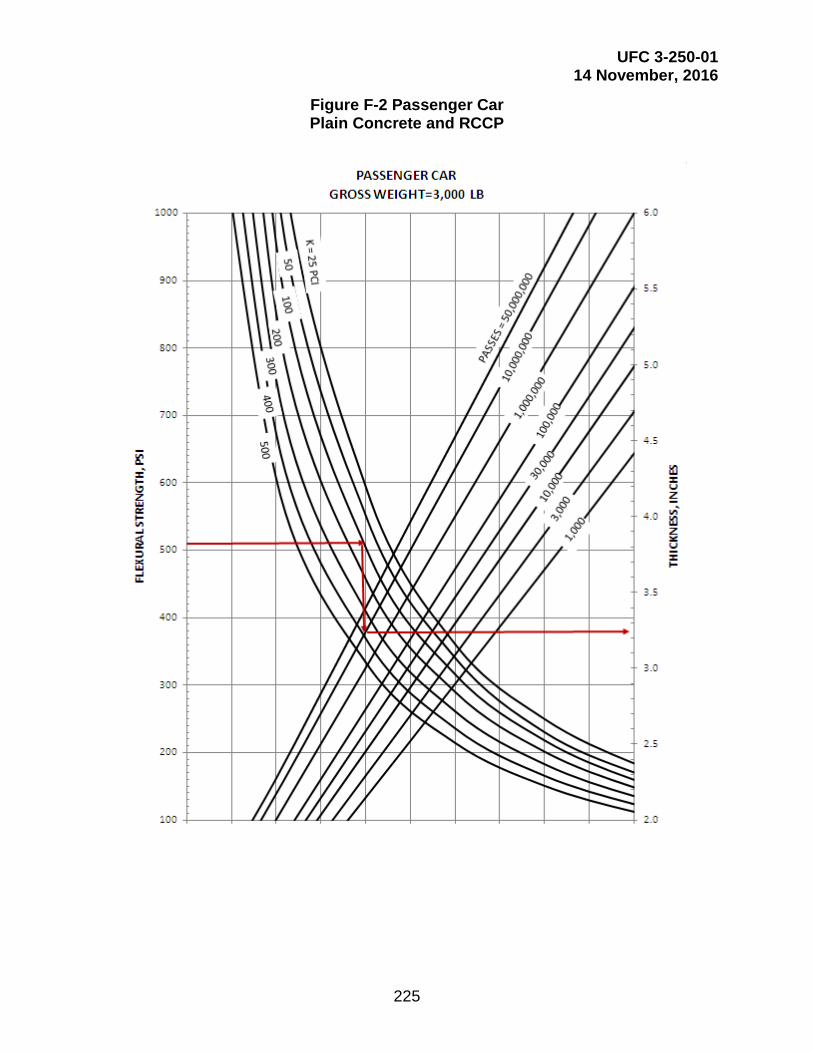
UFC 3-250-01 14 November, 2016
225
Figure F-2 Passenger Car Plain Concrete and RCCP

UFC 3-250-01 14 November, 2016
226
Figure F-3 Light Strike Vehicle Plain Concrete and RCCP

UFC 3-250-01 14 November, 2016
227
Figure F-4 M1A1 Main Tank Tracked Plain Concrete and RCCP
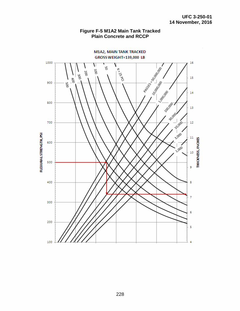
UFC 3-250-01 14 November, 2016
228
Figure F-5 M1A2 Main Tank Tracked Plain Concrete and RCCP

UFC 3-250-01 14 November, 2016
229
Figure F-6 M2A3, Bradley Vehicle Tracked Plain Concrete and RCCP
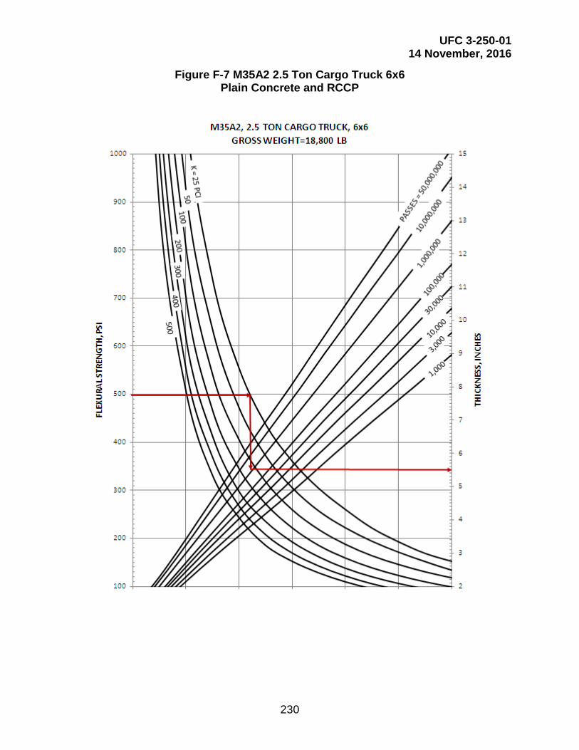
UFC 3-250-01 14 November, 2016
230
Figure F-7 M35A2 2.5 Ton Cargo Truck 6x6 Plain Concrete and RCCP

UFC 3-250-01 14 November, 2016
231
Figure F-8 M60A3 Main Tank Tracked Plain Concrete and RCCP

UFC 3-250-01 14 November, 2016
232
Figure F-9 M109A6, 155 Howitzer Tracked Plain Concrete and RCCP

UFC 3-250-01 14 November, 2016
233
Figure F-10 M113A1, Armored Carrier Tracked Plain Concrete and RCCP

UFC 3-250-01 14 November, 2016
234
Figure F-11 M923 5-Ton Cargo Truck Plain Concrete and RCCP

UFC 3-250-01 14 November, 2016
235
Figure F-12 M977 HEMTT, 10-Ton Cargo Truck 8x8 Plain Concrete and RCCP

UFC 3-250-01 14 November, 2016
236
Figure F-13 M978 HEMTT, 10-Ton Fuel Truck 8x8 Plain Concrete and RCCP

UFC 3-250-01 14 November, 2016
237
Figure F-14 M983 HEMTT, w/XM860A1 Trailer Plain Concrete and RCCP

UFC 3-250-01 14 November, 2016
238
Figure F-15 M998 HMMWV, 1.25-Ton Carrier 4x4 Plain Concrete and RCCP

UFC 3-250-01 14 November, 2016
239
Figure F-16 M988B RTCH Forklift Plain Concrete and RCCP
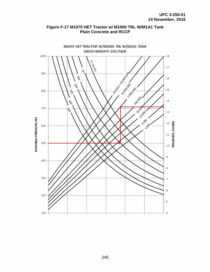
UFC 3-250-01 14 November, 2016
240
Figure F-17 M1070 HET Tractor w/ M1000 TRL W/M1A1 Tank Plain Concrete and RCCP
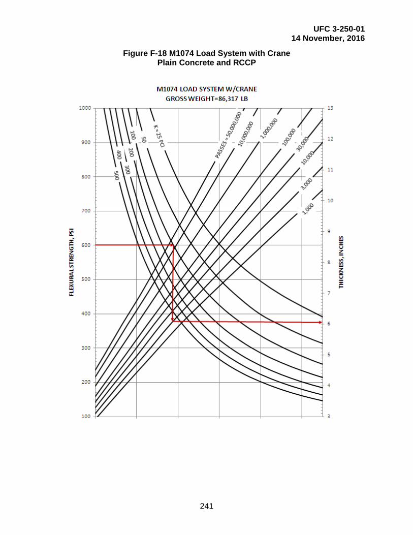
UFC 3-250-01 14 November, 2016
241
Figure F-18 M1074 Load System with Crane Plain Concrete and RCCP
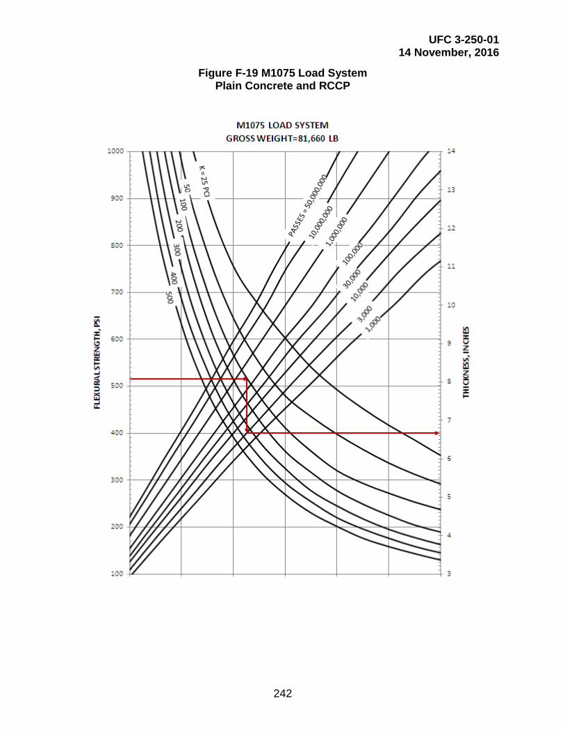
UFC 3-250-01 14 November, 2016
242
Figure F-19 M1075 Load System Plain Concrete and RCCP

UFC 3-250-01 14 November, 2016
243
Figure F-20 M1075 Load System w/M1076 Trailer Plain Concrete and RCCP

UFC 3-250-01 14 November, 2016
244
Figure F-21 M1078 2-1/2 Ton Cargo Truck 4x4 Plain Concrete and RCCP

UFC 3-250-01 14 November, 2016
245
Figure F-21 P-22 Crash Truck (Fire Truck) Plain Concrete and RCCP

UFC 3-250-01 14 November, 2016
246
Figure F-23 R-11 Refueler Plain Concrete and RCCP

UFC 3-250-01 14 November, 2016
247
Figure F-24 Small Pickup Plain Concrete and RCCP
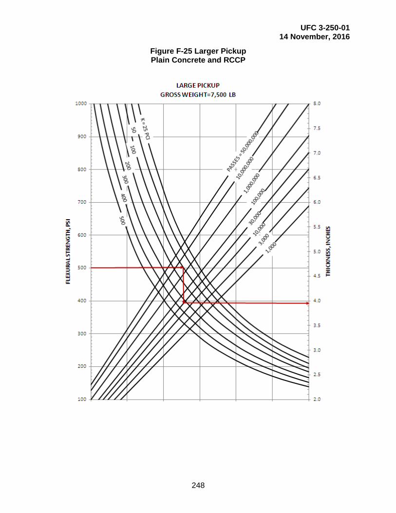
UFC 3-250-01 14 November, 2016
248
Figure F-25 Larger Pickup Plain Concrete and RCCP

UFC 3-250-01 14 November, 2016
249
Figure F-26 Truck 3-Axle Plain Concrete and RCCP

UFC 3-250-01 14 November, 2016
250
Figure F-27 Truck 4-Axle Plain Concrete and RCCP
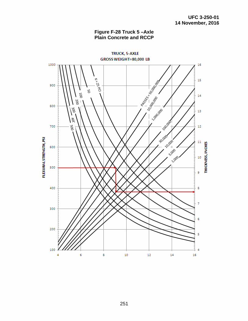
UFC 3-250-01 14 November, 2016
251
Figure F-28 Truck 5 –Axle Plain Concrete and RCCP

UFC 3-250-01 14 November, 2016
252
Figure F-29 Truck 2-Axle, 6-Tire Plain Concrete and RCCP

UFC 3-250-01 14 November, 2016
253
Figure F-30 TYC-850L Container Truck Plain Concrete and RCCP
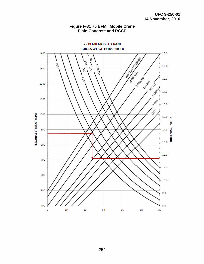
UFC 3-250-01 14 November, 2016
254
Figure F-31 75 BFMII Mobile Crane Plain Concrete and RCCP

UFC 3-250-01 14 November, 2016
255
This Page Intentionally Left Blank
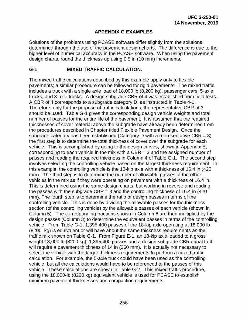
UFC 3-250-01 14 November, 2016
256
APPENDIX G EXAMPLES
Solutions of the problems using PCASE software differ slightly from the solutions determined through the use of the pavement design charts. The difference is due to the higher level of numerical accuracy in the PCASE software. When using the pavement design charts, round the thickness up using 0.5 in (10 mm) increments.
G-1 MIXED TRAFFIC CALCULATION.
The mixed traffic calculations described by this example apply only to flexible pavements; a similar procedure can be followed for rigid pavements. The mixed traffic includes a truck with a single axle load of 18,000 lb (8,200 kg), passenger cars, 5-axle trucks, and 3-axle trucks. A design subgrade CBR of 4 was established from field tests. A CBR of 4 corresponds to a subgrade category D, as instructed in Table 4-1. Therefore, only for the purpose of traffic calculations, the representative CBR of 3 should be used. Table G-1 gives the corresponding design vehicle weights and total number of passes for the entire life of the pavement. It is assumed that the required thicknesses of cover material above the subgrade have already been determined from the procedures described in Chapter titled Flexible Pavement Design. Once the subgrade category has been established (Category D with a representative CBR = 3), the first step is to determine the total thickness of cover over the subgrade for each vehicle. This is accomplished by going to the design curves, shown in Appendix E, corresponding to each vehicle in the mix with a CBR = 3 and the assigned number of passes and reading the required thickness in Column 4 of Table G-1. The second step involves selecting the controlling vehicle based on the largest thickness requirement. In this example, the controlling vehicle is the 18-kip axle with a thickness of 16.4 in (420 mm). The third step is to determine the number of allowable passes of the other vehicles in the mix as if they were operating on pavement with a thickness of 16.4 in. This is determined using the same design charts, but working in reverse and reading the passes with the subgrade CBR = 3 and the controlling thickness of 16.4 in (420 mm). The fourth step is to determine the ratio of design passes in terms of the controlling vehicle. This is done by dividing the allowable passes for the thickness section (of the controlling vehicle) by the allowable passes of each vehicle (shown in Column 5). The corresponding fractions shown in Column 6 are then multiplied by the design passes (Column 3) to determine the equivalent passes in terms of the controlling vehicle. From Table G-1, 1,395,400 passes of the 18-kip axle operating at 18,000 lb (8200 kg) is equivalent or will have about the same thickness requirements as the traffic mix shown on Table G-1. From Figure E-1, an 18-kip axle loaded to a gross weight 18,000 lb (8200 kg), 1,395,400 passes and a design subgrade CBR equal to 4 will require a pavement thickness of 14 in (350 mm). It is actually not necessary to select the vehicle with the larger thickness requirements to perform a mixed traffic calculation. For example, the 5-axle truck could have been used as the controlling vehicle, but all the calculations would have to be referenced to the passes of this vehicle. These calculations are shown in Table G-2. This mixed traffic procedure, using the 18,000-lb (8200 kg) equivalent vehicle is used for PCASE to establish minimum pavement thicknesses and compaction requirements.

UFC 3-250-01 14 November, 2016
257
G-2 COMPACTION REQUIREMENTS.
Two examples illustrating the application of subgrade compaction requirements are as follows:
G-2.1 Example 1: Cohesionless Subgrade.
Assume clean cohesionless sand and a design CBR of 18, with a natural in-place density of 90 percent of maximum density to beyond the depth of exploration of 6 ft (1.8 m). From Table 5-1 for less than 5.7 million equivalent 18,000 lb (8,200 kg) single axle loads, it is found that 100 percent density must extend to a depth of 12 in (300 mm) below the pavement surface. Below this depth, fill sections must be compacted to 95 percent maximum density throughout, and cut sections to 95 percent of maximum density to a depth of 22 in (560 mm) below the pavement surface. The designer must decide from previous experience or from test pavement section data whether or not these percentages of compaction in cut sections can be obtained from the top of the subgrade. If they cannot, a part of the subgrade must be removed, the underlying layer compacted, and the material replaced, or the thickness of select material or subbase must be so increased that the densities in the un-compacted subgrade will be adequate.
Table G-1 Example of Mixed Traffic Calculations for a Flexible Pavement
(1) Vehicle
(2) Gross
Weight, lb (kg)
(3) Design Total
Passes
(4) Required1 Thickness
in (mm)
(5) Allowable
Passes
(6)=1,000,000/(5) Ratio of Passes
in Terms of Controlling
Vehicle
(7)=(6)*(3)
Equivalent Passes of
Controlling Vehicle
18,000 lb (8,200 kg) ESAL
18,000 lb (8,200
kg)
1,000,000 16.4 (420) 1,000,000 1.000 1,000,000
Passenger Car
3,000 (1,400)
20,000,000 6.1 (160) Unlimited 0.000 0
5-Axle Truck 80,000 (27,000)
100,000 15.8 (401) 252,915 3.954 395,400
3-Axle Truck 35,000 (16,000)
500,000 12.8 (325) Unlimited 0.000 0
Equivalent Passes in Terms of 18-kip ESAL = 1,395,400 1 Required thickness based on CBR=3 (Subgrade Category D).
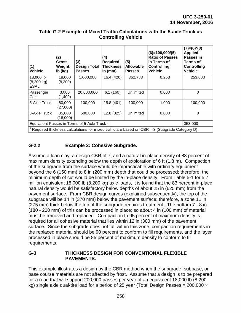
UFC 3-250-01 14 November, 2016
258
Table G-2 Example of Mixed Traffic Calculations with the 5-axle Truck as Controlling Vehicle
(1) Vehicle
(2) Gross Weight, lb (kg)
(3) Design Total Passes
(4) Required1 Thickness in (mm)
(5) Allowable Passes
(6)=100,000/(5) Ratio of Passes in Terms of Controlling Vehicle
(7)=(6)*(3)
Applied Passes in Terms of Controlling Vehicle
18,000 lb (8,200 kg) ESAL
18,000 (8,200)
1,000,000 16.4 (420) 362,788 0.253 253,000
Passenger Car
3,000 (1,400)
20,000,000 6.1 (160) Unlimited 0.000 0
5-Axle Truck 80,000 (27,000)
100,000 15.8 (401) 100,000 1.000 100,000
3-Axle Truck 35,000 (16,000)
500,000 12.8 (325) Unlimited 0.000 0
Equivalent Passes in Terms of 5-Axle Truck = 353,000 1 Required thickness calculations for mixed traffic are based on CBR = 3 (Subgrade Category D)
G-2.2 Example 2: Cohesive Subgrade.
Assume a lean clay, a design CBR of 7, and a natural in-place density of 83 percent of maximum density extending below the depth of exploration of 6 ft (1.8 m). Compaction of the subgrade from the surface would be impracticable with ordinary equipment beyond the 6 (150 mm) to 8 in (200 mm) depth that could be processed; therefore, the minimum depth of cut would be limited by the in-place density. From Table 5-1 for 5.7 million equivalent 18,000 lb (8,200 kg) axle loads, it is found that the 83 percent in-place natural density would be satisfactory below depths of about 25 in (625 mm) from the pavement surface. From CBR design curves (explained subsequently), the top of the subgrade will be 14 in (370 mm) below the pavement surface; therefore, a zone 11 in (275 mm) thick below the top of the subgrade requires treatment. The bottom 7 - 8 in (180 - 200 mm) of this can be processed in place; so about 4 in (100 mm) of material must be removed and replaced. Compaction to 95 percent of maximum density is required for all cohesive material that lies within 12 in (300 mm) of the pavement surface. Since the subgrade does not fall within this zone, compaction requirements in the replaced material should be 90 percent to conform to fill requirements, and the layer processed in place should be 85 percent of maximum density to conform to fill requirements.
G-3 THICKNESS DESIGN FOR CONVENTIONAL FLEXIBLE PAVEMENTS.
This example illustrates a design by the CBR method when the subgrade, subbase, or base course materials are not affected by frost. Assume that a design is to be prepared for a road that will support 200,000 passes per year of an equivalent 18,000 lb (8,200 kg) single axle dual-tire load for a period of 25 year (Total Design Passes = 200,000 ×

UFC 3-250-01 14 November, 2016
259
25 = 5,000,000). Further, assume that compaction requirements will necessitate an increase in subgrade density to a depth of 6 in (150 mm) below the subgrade surface and that a soft layer occurs within the subgrade 24 in (600 mm) below the subgrade surface. The CBR design values of the various subgrade layers and the materials available for subbase and base course construction are as follows:
Material Soil Classification Design CBR Base GM (limerock) 80 Subbase GP 25 Compacted subgrade CL 10 Natural subgrade CL 7 Weak layer in subgrade CH 4
The total pavement thickness and thicknesses of the various subbase and base layers are determined according the following procedure.
G-3.1 Total Thickness.
The total thickness of subbase, base, and bituminous surface will be governed by the CBR of the compacted subgrade. From the flexible pavement design curves shown in Figure E-1, the required total thickness above the compacted subgrade (CBR of 10) is 7.8 in (195 mm) to protect from 5,000,000 passes of 18,000 lb (8,200 kg) equivalent single axle. A check must be made of the adequacy of the strength of the natural subgrade and of the weak layer within the subgrade. From the curves in Figure E-1, the required cover for these two layers is 9.8 in and 14.5 in (245 mm and 370 mm), respectively. If the design thickness is 7.8 in (195 mm) and the subgrade is compacted to 6 in (150 mm) below the subgrade surface, the natural subgrade will be covered by a total of 7.8 in (195 mm) + 6 in (150 mm) = 13.8 in (345 mm) of higher strength material. Similarly, the soft layer occurring 24 in (600 mm) below the subgrade surface will be protected by 7.8 in (195 mm) + 24 in (600 mm) = 31.8 in (795 mm) of total cover. Thus, the cover is adequate in both cases.
G-3.2 Minimum Base and Pavement Thicknesses.
As indicated in Table 7-2 for 5,000,000 passes of an 18,000 lb (8,200 kg) equivalent single axle, dual-tire load, the minimum base thickness is 4 in (100 mm) and the pavement thickness is 3.5 in (89 mm).
G-3.3 Thickness of Subbase and Base Courses.
The design thickness of the base and subbase will depend upon the CBR design value of each material. The total thickness of subbase, base, and pavement, as determined above, is 7.8 in (195 mm). The thickness required above the subbase (CBR = 25), as determined from Figure E-1, is 3.4 in (83 mm); therefore, the required thickness of subbase is 7.8 in (195 mm) – 3.4 in (83 mm) = 4.4 in (112 mm). The 3.4 in (83 mm) layer required above the subbase will be composed of a base course and pavement; however, adjustments must be made in the thicknesses of the base and the pavement

UFC 3-250-01 14 November, 2016
260
to comply with minimum thickness requirements, which is a combined thickness of pavement and base of 7.5 in (183) = 3.5 in (83 mm) of asphalt surface and 4 in (100 mm) of base. Therefore, the final design will consist of a 4 in (100 mm) subbase course, a 4 in (100 mm) base course, and a 3.5 in (83 mm) pavement.
G-4 THICKNESS DESIGN FOR STABILIZED SOIL LAYERS.
To use the equivalency factors requires that a conventional flexible pavement be designed to support the design load conditions. If it is desired to use a stabilized base or subbase course, the thickness of conventional base or subbase is divided by the equivalency factor for the applicable stabilized soil.
G-4.1 Example 1.
Assume a conventional flexible pavement has been designed which requires a total thickness of 16 in (410 mm) above the subgrade. The minimum thickness of AC and base is 2 and 4 in (50 and 100 mm), respectively, and the thickness of subbase is 10 in (250 mm). It is desired to replace the base and subbase with a cement-stabilized gravelly soil (GP) having an unconfined compressive strength of 890 psi (6.1 MPa). The material qualifies for application as base course since its strength is greater than 750 psi (5.2 MPa), as required by the UFC 3-250-11. From Table 9-1 the equivalency factor for a base is 1.15. Therefore, 4 in ÷ 1.15 = 3.5 in (100 mm ÷ 1.15 = 87 mm) of stabilized base course. Since the minimum required thickness is 4 in (100 mm), the excess of stabilized base course of 4 in – 3.5 in = 0.5 in (100 mm – 87 mm = 13 mm) is computed as equivalent thickness of non-stabilized subbase material, which is equal to 0.5 in. * 2.3 = 1.1 in (13 mm * 2.3 = 30 mm). This equivalent subbase thickness is accounted in the stabilized base; therefore the needed non-stabilized subbase is thinner than 10 in (250 mm) and equal to 10 in – 1.1 in = 8.9 in (250 mm - 30 mm = 220 mm). The next step includes the calculation of the equivalent thickness of subbase stabilized material, as 8.9 in ÷ 2.3 = 3.86 in (220 mm ÷ 2.3 = 96 mm). The required minimum thickness for stabilize subbase is 4 in (100 mm). Therefore, the total thickness of the cement-stabilized pavement is 2 in (50 mm) of AC, 4 (100 mm) in of cement-stabilized gravelly soil base, and 4 in (100 mm) of cement-stabilized gravelly soil subbase.
G-4.2 Example 2.
Assume a conventional flexible pavement has been designed which requires 3.5 in (89 mm) of AC surface, 4 in (100 mm) of crushed stone base, and 18 in (460 mm) of subbase. It is desired to construct bituminous pavement. The equivalency factor from Table 9-1 for a base course is 1.15 and for a subbase 2.30. The thickness of AC required to replace the base is 4 in. ÷ 1.15 = 3.5 in (100 mm ÷ 1.15 = 87 mm). Since the minimum required thickness is 4 in, the excess of stabilized base course of 4 in – 3.5 in = 0.5 in (100 mm – 87 mm = 13 mm) is computed as equivalent thickness of non-stabilized subbase material, which is equal to 0.5 in. * 2.3 = 1.1 in (13 mm * 2.3 = 30 mm). This equivalent subbase thickness is accounted in the stabilized base; therefore the needed non-stabilized subbase is thinner than 18 in (460 mm) and equal to 18 in – 1.1 in = 16.9 in) (460 mm – 30 mm = 440 mm) The next step computes the equivalent thickness of subbase stabilized material, as 16.9 in. ÷ 2.3 = 7.3 in (440 mm ÷ 2.3 = 190

UFC 3-250-01 14 November, 2016
261
mm). The total thickness of the ABC pavement is 3.5 in + 4 in + 7.3 in = 14.8 in~ 15 in (87 + 100 + 190 = 377 mm ~ 380 mm)
G-5 THICKNESS DESIGN FOR RIGID PAVEMENTS.
G-5.1 Example 1: Non-Stabilized.
A road is to be designed on a non-stabilized foundation for the following traffic and subgrade conditions:
Traffic:
Passenger Cars, 3,000 lb (1,400 kg) 2,400 passes/day
3-Axle Truck, 35,000 lb (16,000 kg) 120 passes/day
5-Axle Truck, 80,000 lb (27,000 kg) 80 passes/day
M1A2 Tank, 139,000 lb (63,000 kg) 16 passes/day
Subgrade:
k-value = 100 psi/in (27 kPa/mm)
Concrete:
28-day Flexural strength = 750 psi (5.2 MPa)
Modulus of Elasticity = 4,000,000 psi (27,600 MPa)
Design Life: 25 years
For these design conditions and using the mixed traffic procedures described in Chapter titled Vehicular Traffic with a subgrade category C (k-value equal to 147 psi/in (40 kPa/mm)), the equivalent passes in terms of the M1A2 tank are computed and are shown in Table G-3. From Figure F-5, 147,295 passes of an M1A2 tank results in a required thickness of 7.8 in (198 mm). Rounding up in 0.5 in (10 mm) increments to a final thickness will be 8 in (200 mm).
UFC 3-250-01 14 November, 2016
262
G-5.2 Example 2: Stabilized Soil.
A rigid pavement, functioning as road is to be designed over a 6 in (150 mm) stabilized soil having an Ef = 650,000 psi (4,500 MPa) for the following traffic and subgrade conditions:
Traffic:
M1A2 Tank, 139,000 lb (63,000 kg) 40 passes/day
M2A3 Tank, 58,200 lb (26,400 kg) 16 passes/day
M923 5-Ton, 32,500 lb (14,700 kg) 80 passes/day
M978 HEMMT, 59,000 lb (26,800 kg) 80 passes/day
M998 HMMWV, 7,900 lb (3,600 kg) 160 passes/day
Subgrade:
k-value = 100 psi/in (27 kPa/mm)
Concrete:
28-day Flexural strength = 750 psi (5.2 MPa)
Modulus of Elasticity = 4,000,000 psi (27,600 MPa)
Design Life: 25 years
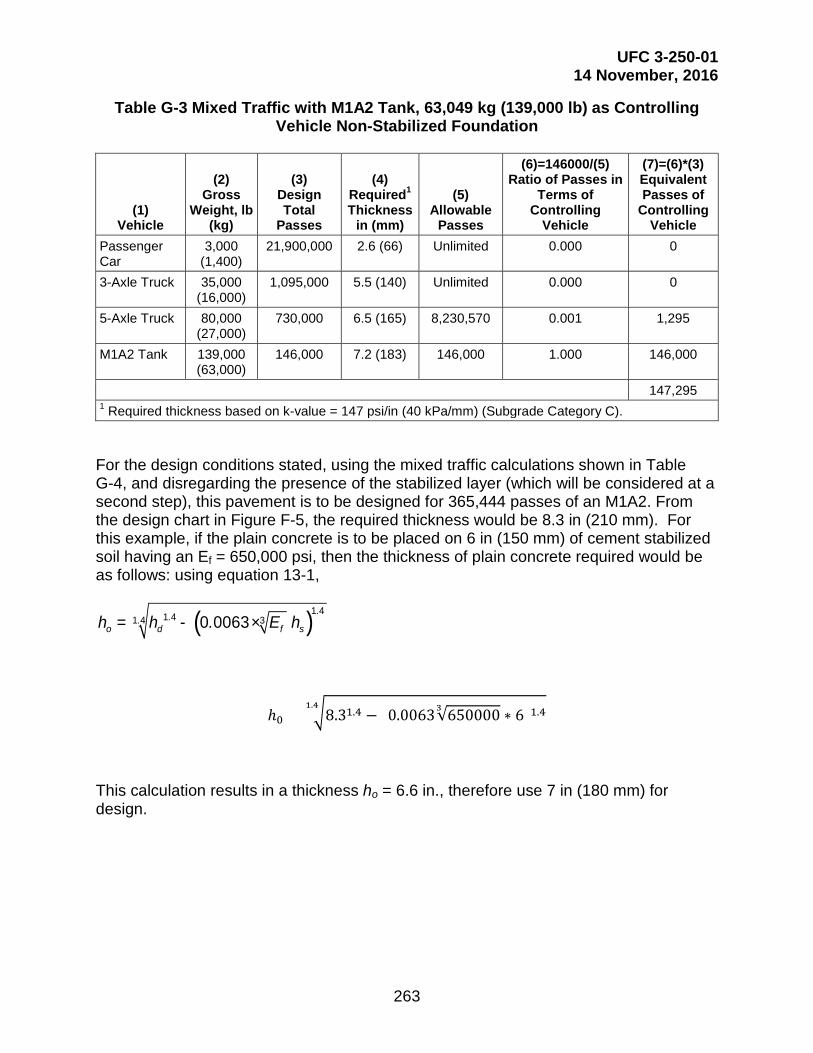
UFC 3-250-01 14 November, 2016
263
Table G-3 Mixed Traffic with M1A2 Tank, 63,049 kg (139,000 lb) as Controlling Vehicle Non-Stabilized Foundation
(1) Vehicle
(2) Gross
Weight, lb (kg)
(3) Design Total
Passes
(4) Required1 Thickness
in (mm)
(5) Allowable
Passes
(6)=146000/(5) Ratio of Passes in
Terms of Controlling
Vehicle
(7)=(6)*(3) Equivalent Passes of
Controlling Vehicle
Passenger Car
3,000 (1,400)
21,900,000 2.6 (66) Unlimited 0.000 0
3-Axle Truck 35,000 (16,000)
1,095,000 5.5 (140) Unlimited 0.000 0
5-Axle Truck 80,000 (27,000)
730,000 6.5 (165) 8,230,570 0.001 1,295
M1A2 Tank 139,000 (63,000)
146,000 7.2 (183) 146,000 1.000 146,000
147,295 1 Required thickness based on k-value = 147 psi/in (40 kPa/mm) (Subgrade Category C).
For the design conditions stated, using the mixed traffic calculations shown in Table G-4, and disregarding the presence of the stabilized layer (which will be considered at a second step), this pavement is to be designed for 365,444 passes of an M1A2. From the design chart in Figure F-5, the required thickness would be 8.3 in (210 mm). For this example, if the plain concrete is to be placed on 6 in (150 mm) of cement stabilized soil having an Ef = 650,000 psi, then the thickness of plain concrete required would be as follows: using equation 13-1,
( )1 41 41 4 30 0063...
o d f sh h . E h= - ×
ℎ0 = �8.31.4 − (0.0063√6500003 ∗ 6)1.41.4
This calculation results in a thickness ho = 6.6 in., therefore use 7 in (180 mm) for design.

UFC 3-250-01 14 November, 2016
264
Table G-4 Mixed Traffic with M1A2, 63,049 kg (139,000 lb) as Controlling Vehicle Stabilized Foundation
(1) Vehicle
(2) Gross
Weight, lb (kg)
(3) Design Total
Passes
(4) Required1 Thickness
in (mm)
(5) Allowable
Passes
(6)=365000/(5) Ratio of Passes
in Terms of Controlling
Vehicle
(7)=(6)*(3)
Equivalent Passes of
Controlling Vehicle
M1A2 Tank
139,000 (63,000)
365,000 7.6 (190) 365,000 1.000 365000
M2A3 Tank
58,200 (26,400)
146,000 5.7 (150) Unlimited 0.00 0
M923 5-ton
32,500 (14,700)
730,000 4.3 (110) Unlimited 0.00 0
M978 HEMMT
59,000 (26,800)
730,000 6.6 (170) 6 x 10⁸ 0.0006 444
M998 HMMWV
7,900 (3,600)
1,460,000 3.4 (86) Unlimited 0.00 0
365,444 1 Required thickness based on k-value = 147 psi/in (40 kPa/mm) (Subgrade Category C).
G-6 REINFORCED CONCRETE PAVEMENTS.
A design example for a reinforced concrete pavement requires a plan concrete thickness of 7.9 in (200 mm) for given traffic and subgrade conditions. The percentage of longitudinal reinforcing steel S required to reduce the pavement thickness to 7 in (180) mm) is obtained from Figure 14-1 as 0.10 percent. Similarly, the percentage of longitudinal reinforcing steel required to reduce the pavement thickness to 6 in (150 mm) is 0.30 percent. From paragraph titled Thickness Design On Unbound Base Or Subbase, the percentage of transverse reinforcing steel would be either 0.05 for a design thickness of 7 in or 0.15 for a design thickness of 6 in. The choice of which percentage of steel reinforcement to use should be based on economic factors, foundation, and climatic conditions peculiar to the project area. If the yield strength of the steel is assumed to be 60,000 psi (410 MPa), the maximum allowable spacing of the transverse contraction joints would be 49 ft (15 m) for 0.10 percent longitudinal steel, and 97 ft (30 m) as the maximum spacing for 0.30 percent longitudinal steel. In the latter case, the maximum permissible spacing of 75 ft (25 m) would be used.
G-7 OVERLAY DESIGN.
Design an overlay for an existing road having a plain concrete thickness of 6 in (150 mm), a flexural strength of 650 psi (4.5 MPa), a subgrade k value of 100 pci (27 kPa/mm), and a projected design traffic of 20 million of an 18,000 lb (8,200 kg) ESAL. The concrete overlay will also have a flexural strength of 650 psi. The factor for projecting cracking in a flexible overlay is 0.93 from Figure 15-1. The existing pavement is in good condition with little or no structural cracking. The condition factor C is therefore equal to 1.0 for concrete and flexible overlay. From Figure F-1, hd is 8.1 in

UFC 3-250-01 14 November, 2016
265
(206 mm.). Overlay thickness requirements for the various types of overlays are as follows:
G-7.1 Bonded Overlay
ho = hd - hE
ho = 8.1 – 6 in (206 - 150 mm)
ho = 2.1 in (56 mm); round up in 0.5 in (10 mm) increments to 2.5 in. (60 mm)
G-7.2 Partially Bonded Overlay
4.14.14.1
×−= E
e
ddo h
hh
Chh
4.14.14.1 0.6
1.81.80.11.8
×−=oh
ho = 3.7 in. (94 mm); round up in 0.5 in (10 mm) increments to 4 in. (100 mm)
G-7.3 Un-bonded Overlay
22
×−= E
e
ddo h
hh
Chh
22 0.6
1.81.80.11.8
×−=oh
ho = 5.4 in. (137 mm); round up in 0.5 in (10 mm) increments to 5.5 in. (140 mm)
G-7.4 Flexible Overlay
( )3o d Et F h C h= × × - ×
to = 3.0 (0.93 × 8.1- 1.0 × 6)
to = 4.6 in (117 mm); round up in 0.5 in (10 mm) increments to 5.0 in. (120 mm)
G-8 DESIGN FOR SEASONAL FROST CONDITIONS.
Design a flexible and a rigid pavement for the following conditions:

UFC 3-250-01 14 November, 2016
266
G-8.1 Site and Traffic Characteristics.
Class B (rolling terrain within the "built-up area").
Category III.
Design Traffic. 1,200,000 18-kip ESAL.
Design Freezing Index. 700 degrees Fahrenheit-days.
G-8.2 Subgrade Material.
Uniform sandy clay, CL
Plasticity index, 18
Frost group, F3
Water content, 20 percent (average) Normal-period CBR, 10
Normal-period modulus of subgrade reaction
k = 200 psi/in (54 kPa/mm) on subgrade and 325 psi/in (88 kPa/mm) on 22 in 560 mm) of base course.
G-8.3 Base Course Material.
Crushed gravel (GW), normal-period CBR = 80, 30 percent passing No. 10 sieve, 1 percent passing No. 200 sieve, and water content = 5%.
G-8.4 Subbase Course Material.
Coarse to fine silty sand (SP-SM), normal period CBR=20, 11 percent passing No. 200 sieve, 6 percent finer than 0.02 mm, frost classification 52, meets filter criteria for material in contact with subgrade.
G-8.5 Average Dry Unit Weight
(good quality base and subbase, 135 pounds per cubic feet (2160 kg/m3))
G-8.6 Average Water Content after Drainage
(good quality base and subbase, 5 percent)
G-8.7 Highest Groundwater.
About 4 ft (1.2 m) below surface of subgrade.
G-8.8 Concrete Flexural Strength.
4.5 MPa (650 psi).

UFC 3-250-01 14 November, 2016
267
G-8.9 Flexible Pavement Design by Limited Subgrade Frost Penetration Method.
From Figure 19-4, the combined thickness a of pavement and base to prevent freezing of the subgrade in the design freezing index year is 45 in (1140 mm). According to criteria in Table 7-2, the minimum pavement thickness is 3.0 in (75 mm) over a CBR = 80 base course that must be at least 4 in (100 mm) thick. The base thickness for zero frost penetration is 45 - 3.0 = 42 in (1140 – 75 = 1065 mm). The ratio of subgrade to base water content is r = 20/5 =4. Since this is a highway pavement, the maximum allowable r of 3 is used in Figure 19-5 to obtain the required thickness of base b of 26 in (660 mm), which would allow about 6 in (150 mm) of frost penetration into the subgrade in the design year. Subgrade preparation would not be required since the combined thickness of pavement and base is more than one-half the thickness required for complete protection.
G-8.10 Flexible Pavement Design by Reduced Subgrade Strength Method.
From the REDUCED SUBGRADE STRENGTH section, paragraph titled Reduced Subgrade Strength, the frost-area soil support index is 3.5, which, from the design curve (Figure E-1) yields a required combined thickness of pavement and base of 16 in (410 mm). Since this is less than the limited subgrade frost penetration method required thickness of 29 in (740 mm), of which 3 in (75 mm) is the required AC layer and 26 in (665 mm.) is granular material,, the 16 in thickness would be used. The pavement structure could be composed of 3 in of AC, 6 in (150 mm) of crushed gravel (since the crushed gravel contains only 1 percent passing the No. 200 sieve, it also serves as the free-draining layer directly beneath the pavement), and 7 in (180 mm) of silty sand subbase material. Subgrade preparation would be required to a depth of 26 – 16 = 10 in (665 – 410 = 255 mm).
G-8.11 Rigid Pavement Design by Limited Subgrade Frost Penetration Method.
From Figure F-1, the required concrete slab thickness p, based on the normal period k = 325 psi per inch (88 kPa/mm), the concrete flexural strength of 650 psi (4.5 MPa) and 1,200,000 ESAL, is 6.3 in (use 6.5 in (165 mm)). From Figure 19-4, the combined thickness of pavement and base for zero frost penetration is 45 in (1140 mm), equivalent to that for the flexible pavement. By use of r = 3 and a thickness of base for zero frost penetration of 45 – 6.5 = 38.5 in (1140 – 165 = 975 mm) in Figure 19-5, the required thickness of base b is 22 in (560 mm), which would allow about 5.5 in (140 mm.) of frost penetration into the subgrade in the design year. No subgrade preparation would be required.
G-8.12 Rigid Pavement Design by the Reduced Subgrade Strength Method.
Since frost heave has not been a major problem, a minimum of 4 in (100 mm) of the free-draining base course material could be used, plus 4 in of the subbase that will serve as a filter material on the subgrade. For this case (8 in (200 mm) of base and
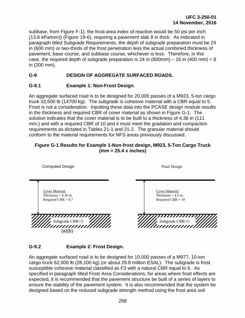
UFC 3-250-01 14 November, 2016
268
subbase, from Figure F-1), the frost-area index of reaction would be 50 psi per inch (13.6 kPa/mm)) (Figure 19-6), requiring a pavement slab 8 in thick. As indicated in paragraph titled Subgrade Requirements, the depth of subgrade preparation must be 24 in (600 mm) or two-thirds of the frost penetration less the actual combined thickness of pavement, base course, and subbase course, whichever is less. Therefore, in this case, the required depth of subgrade preparation is 24 in (600mm) – 16 in (400 mm) = 8 in (200 mm).
G-9 DESIGN OF AGGREGATE SURFACED ROADS.
G-9.1 Example 1: Non-Frost Design.
An aggregate surfaced road is to be designed for 20,000 passes of a M923, 5-ton cargo truck 32,500 lb (14700 kg). The subgrade is cohesive material with a CBR equal to 5. Frost is not a consideration. Inputting these data into the PCASE design module results in the thickness and required CBR of cover material as shown in Figure G-1. The solution indicates that the cover material is to be built to a thickness of 4.36 in (111 mm.) and with a required CBR of 10 and it must meet the gradation and compaction requirements as dictated in Tables 21-1 and 21-2. The granular material should conform to the material requirements for NFS areas previously discussed.
Figure G-1 Results for Example 1-Non-frost design, M923, 5-Ton Cargo Truck (mm = 25.4 x inches)
(a)(b)
G-9.2 Example 2: Frost Design.
An aggregate surfaced road is to be designed for 10,000 passes of a M977, 10-ton cargo truck 62,000 lb (28,100 kg) (or about 29.8 million ESAL). The subgrade is frost susceptible cohesive material classified as F3 with a natural CBR equal to 6. As specified in paragraph titled Frost Area Considerations, for areas where frost effects are expected, it is recommended that the pavement structure be built of a series of layers to ensure the stability of the pavement system. It is also recommended that the system be designed based on the reduced subgrade strength method using the frost area soil
Cover Material: Thickness = 4.36 in. Required CBR = 9.7
Subgrade CBR=5
Cover Material: Thickness = 4.5 in. Required CBR = 10
Subgrade CBR=5
Computed Design Final Design

UFC 3-250-01 14 November, 2016
269
support indices FASSI values listed in Table 19-3 (for F3 soil FASSI is equal to 3.5). Therefore for construction purposes, the pavement structure will consist of:
- A wearing surface of fine-graded crushed rock
- A base course of coarse-graded crushed rock
- A subbase of well-graded sand (Frost group F1 and S2) with a CBR = 10
The wearing surface and the base course materials will be crushed aggregate with the same CBR value, then in PCASE these two layers can be treated as a unique layer.
The total required thickness of cover material above the subgrade, using a FASSI value of 3.5, is 10.98 in (279 mm) with a CBR of 21 for the top layers. The required thickness above the subbase (CBR equal to 10) is 6.35 in (161 mm); therefore the layers with CBR equal to 21 require a total thickness of 6.35 in. The subbase thickness is determined by subtracting the thickness required over the 10 CBR from total thickness required over the 3.5 CBR. The resulting subbase thickness is 4.63 in (116 mm). The layer thicknesses results are shown in Figure G-2. As mentioned, the top layer can be divided into two layers constituted of material with the same CBR but different characteristics. The resulting pavement structure may be proportioned by using the minimum of 3 in (75 mm) for wearing, base course, and sand subbase as shown in Figure G-2 (b). Again, each pavement layer must meet the gradation and compaction requirements dictated in Tables 21-1 and 21-2.
Figure G-2 Results for Example 2-Frost design, M977, HEMTT, 10-TON Cargo Truck (1 mm = 25.4 x inches)
(a) (b)
Subbase Well graded Sand (NFS, S1 or S2)
CBR=10
Subgrade F3 Soil, CBR=3.5
Wearing surface Fine graded crushed gravel
Base Coarse graded crushed gravel
6.35”
4.63”
10.98”
Subbase Well graded Sand
(NFS, S1 or S2) CBR=10
Subgrade F3 Soil, CBR=3.5
Wearing surface Fine graded crushed gravel
CBR=26
Base Coarse graded crushed gravel
CBR=26 3”
5”
3”
Computed Design Final Design
11”

UFC 3-250-01 14 November, 2016
270
APPENDIX H DETERMINATION OF FLEXURAL STRENGTH AND MODULUS OF ELASTICITY
H-1 FLEXURAL STRENGTH TEST PROCEDURE.
Use ASTM C78/78M to compute flexural strength.
H-1.1 CALCULATIONS.
H-1.1.1 Modulus of Rupture
Use modulus of rupture equation from ASTM C78/78M.
H-1.2 REPORT.
Provide a test report. Include report items in ASTM C78/78M.
H-2 MODULUS OF ELASTICITY TEST PROCEDURE
Soil stabilization is a method of improving soil properties by blending and mixing other materials. The modulus value for stabilized soils is determined according to the procedures in AASHTO MEPDG.