UEENEEG048B Solve problems in complex multi-path … · DC Networks ... Conventions for solution by...
12
UEE07 Electrotechnology Training Package Learner guide Version 4 Training and Education Support Industry Skills Unit Meadowbank Product Code: 5526 UEENEEG048B Solve problems in complex multi-path power circuits SAMPLE
Transcript of UEENEEG048B Solve problems in complex multi-path … · DC Networks ... Conventions for solution by...
UEE07 Electrotechnology
Training Package
Learner guide
Version 4
Training and Education Support
Industry Skills Unit
Meadowbank
Product Code: 5526
UEENEEG048B
Solve problems in complex multi-path power circuits
SAMPLE

© TAFE NSW (Training & Education Support Industry Skills Unit, Meadowbank)
2011
UEENEEG048B Solve problems in complex multi-path power circuits V4
AcknowledgmentsThe TAFE NSW Training and Education Support Industry Skills Unit, Meadowbank would like to acknowledge the support and assistance of the following people in the production of this learner resource guide:
Writer:David ArnoldWestern InstituteTAFE NSW
Reviewers:Greg BellTAFE NSW
Project Manager:Steve ParkinsonKerry BarlowTAFE NSW
EnquiriesEnquiries about this and other publications can be made to:
Training and Education Support Industry Skills Unit, Meadowbank Meadowbank TAFE Level 3, Building J See Street MEADOWBANK NSW 2114
Tel: 02-9942 3200 Fax: 02-9942 3257
© TAFE NSW (Training and Education Support, Industry Skills Unit Meadowbank) 2011
Copyright of this material is reserved to TAFE NSW Training and Education Support, Industry Skills Unit Meadowbank. Reproduction or transmittal in whole or in part, other than for the purposes of private study or research, and subject to the provisions of the Copyright Act, is prohibited without the written authority of TAFE NSW Training and Education Support, Industry Skills Unit Meadowbank.
ISBN 978-1-74236-270-0
SAMPLE
© TAFE NSW (Training & Education Support Industry Skills Unit, Meadowbank)
2011
UEENEEG048B Solve problems in complex multi-path power circuits V4
TABLE OF CONTENTS
Introduction ......................................................................................... 71. General introduction ................................................................................ 7
2. Using this learner guide .......................................................................... 7
3. Prior knowledge and experience ................................................................ 9
4. Unit of competency overview ................................................................... 9
5. Assessment .......................................................................................... 12
Section 1 Voltage/Current Sources, Kirchhoff’s Law for DC Linear Circuits ..15Voltage sources ......................................................................................... 16
Current sources ......................................................................................... 24
Conversion between sources ....................................................................... 28
Kirchhoff’s Voltage law ................................................................................ 31
Answers to student exercises ...................................................................... 34
Section 2 Superposition principles for D.C. Linear Circuits ........................37DC Networks ............................................................................................. 38
Two-source networks with voltage sources .................................................... 38
Two-source networks with current sources .................................................... 41
Networks with three sources and three meshes .............................................. 44
Answers to student exercises ...................................................................... 47
Section 3 Mesh and Nodal Analysis for D.C. Linear Circuits ......................55Mesh Analysis ........................................................................................... 56
Nodal analysis ........................................................................................... 65
Answers to student exercises ...................................................................... 78
Section 4 Thevenin’s principles for D.C. linear circuits .............................89Thevenin’s Theorem ................................................................................... 90
Two-mesh circuits ...................................................................................... 92
Three-mesh circuits ................................................................................... 94
Answers to student exercises ...................................................................... 99
Section 5 Norton’s principles for D.C. linear circuits ..............................103Norton’s Theorem .....................................................................................104
Three-mesh circuits ..................................................................................107
Source Conversion ....................................................................................108
Circuit simplifi cation by source conversion ....................................................110
Answers to student exercises .....................................................................115
SAMPLE
© TAFE NSW (Training & Education Support Industry Skills Unit, Meadowbank)
2011
UEENEEG048B Solve problems in complex multi-path power circuits V4
Section 6 Phasor Analysis ................................................................. 119Alternating sinusoidal waveforms, angular frequency and units of measurement 120
Peak voltage and frequency ........................................................................ 129
Review Summary ...................................................................................... 131
Supplementary notes ................................................................................ 132
Answers to student exercises ..................................................................... 137
Section 7 Complex impedance ........................................................... 141The impedance triangle ............................................................................. 142
Resistance and Reactance .......................................................................... 142
Admittance, susceptance and conductance ................................................... 146
Real components equivalent series circuit ..................................................... 150
Element voltage drops ............................................................................... 155
Real component equivalent parallel circuits ................................................... 159
Answers to student exercises ..................................................................... 169
Section 8 Series and parallel A.C. linear circuits ................................... 177Series equivalent impedance ...................................................................... 178
Parallel Equivalent Impedance .................................................................... 181
The voltage divider and current splitter ........................................................ 184
Series Parallel AC Circuits .......................................................................... 187
Answers to student exercises ..................................................................... 191
Section 9 Superposition principles and Kirchhoff’s Laws applied to A.C. linear circuits ............................................................................. 197
Voltage drops and voltage rise .................................................................... 198
Conventions for solution by Kirchhoff’s Laws ................................................. 198
Conventions for solution by superposition ..................................................... 198
Solving equations derived by Kirchhoff’s Laws ............................................... 199
Current divider using admittances ............................................................... 202
Solving equations by superposition .............................................................. 204
Answers to student exercises ..................................................................... 208
Section 10 Mesh and Nodal analysis for A.C. linear circuits ...................... 211Currents and mesh analysis ....................................................................... 212
Mesh analysis using determinants ............................................................... 212
Voltages and nodal analysis ........................................................................ 218
Answers to student exercises ..................................................................... 224
Section 11 Thevenin and Norton theorems applied to A.C. linear circuits ... 231Thevenin’s equivalent circuit ....................................................................... 232
Norton’s equivalent circuit .......................................................................... 234
SAMPLE
© TAFE NSW (Training & Education Support Industry Skills Unit, Meadowbank)
2011
UEENEEG048B Solve problems in complex multi-path power circuits V4
Thevenin/Norton source conversion ............................................................. 238
Answers to student exercises ..................................................................... 241
Section 12 Complex A.C. power and maximum power transfer theorem .... 245True power .............................................................................................. 246
Reactive power ......................................................................................... 248
Apparent, reactive and real power ............................................................... 251
Power factor ............................................................................................. 252
Power triangles ......................................................................................... 253
Maximum-power transfer ........................................................................... 255
Proportion of power consumed by a source ................................................... 255
Answers to student exercise ....................................................................... 257
Section 13 Series resonance ............................................................... 261Resistance, reactance, impedance and frequency .......................................... 262
Resonant frequency .................................................................................. 264
Resonant series impedance and power factor ................................................ 264
Voltage magnifi cation factor ....................................................................... 265
Q factor ................................................................................................... 266
Selectivity ................................................................................................ 266
Bandwidth ............................................................................................... 267
Half power (3dB) Points and Powerfactor ...................................................... 268
Practical applications of resonant circuits ...................................................... 271
Problem Resonance ................................................................................... 272
Answers to student exercises ..................................................................... 273
Section 14 Parallel Resonance ............................................................. 277Resistance, reactance and impedance vs. frequency ...................................... 278
Selectivity ................................................................................................ 278
Bandwidth ............................................................................................... 279
Q-Factor in parallel resonant circuits ............................................................ 281
Current amplifi cation ................................................................................. 283
Impedance vs. frequency ........................................................................... 284
Frequency of Maximum Impedance ............................................................. 285
Frequency of Unity power factor ................................................................. 285
Loading of Parallel Resonant Circuits ............................................................ 286
High Q Factor Conditions ............................................................................ 288
Half Power (3dB) Points and Power Factor .................................................... 289
Uses of Resonant Circuits ........................................................................... 289
Problem Resonance ................................................................................... 290
SAMPLE

© TAFE NSW (Training & Education Support Industry Skills Unit, Meadowbank)
2011
UEENEEG048B Solve problems in complex multi-path power circuits V4
Answers to student exercises ..................................................................... 291
Section 15 Transients ......................................................................... 295Transients in R-C circuits ............................................................................ 296
Growth and decay ..................................................................................... 297
Transients in L–R circuits ............................................................................ 301
Answers to student exercises ..................................................................... 305
SAMPLE

© TAFE NSW (Training & Education Support, Industry Skills Unit Meadowbank) 2011 Page 13 of 310
UEENEEG048B Solve problems in complex multi-path power circuits V4
Section 1
Voltage/current sources, Kirchhoff’s law
for DC linear circuits
SAMPLE

© TAFE NSW (Training & Education Support, Industry Skills Unit Meadowbank) 2011 Page 15 of 310
UEENEEG048B Solve problems in complex multi-path power circuits V4
Section 1 Voltage/Current Sources, Kirchhoff’s Law for DC Linear Circuits
Contents
• Voltage sources
• Current sources
• Conversion between sources
• Kirchhoff’s Voltage Law
• Kirchhoff’s Current Law
• Conventions
• Establishing equations
• Solving equations
Learning Objectives
Learners should be able to meet the following learning objectives:
a. Calculate the effect of the internal resistance on terminal voltage and current delivered for practical voltage sources and current sources.
b. Calculate current and voltage in any DC network of up to two loops and three sources.
c. Calculate current and voltage in any AC network of up to two loops and two sources.
d. Describe the function and operation of an electronics circuit simulation program.
e. Enter given circuit specifi cations into an electronic circuit simulation program to determine circuit currents and voltagesSAMPLE
UEENEEG048B Solve problems in complex multi-path power circuits V4
© TAFE NSW (Training & Education Support, Industry Skills Unit Meadowbank) 2011 Page 16 of 310
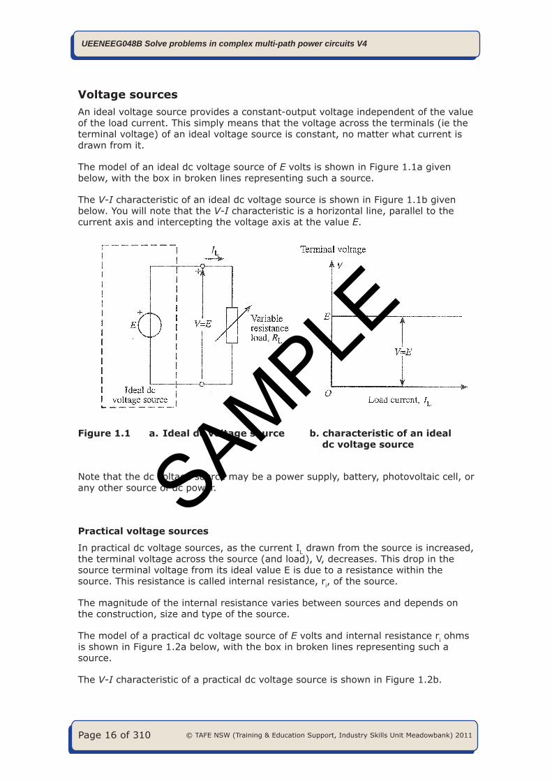
Voltage sourcesAn ideal voltage source provides a constant-output voltage independent of the value of the load current. This simply means that the voltage across the terminals (ie the terminal voltage) of an ideal voltage source is constant, no matter what current is drawn from it.
The model of an ideal dc voltage source of E volts is shown in Figure 1.1a given below, with the box in broken lines representing such a source.
The V-I characteristic of an ideal dc voltage source is shown in Figure 1.1b given below. You will note that the V-I characteristic is a horizontal line, parallel to the current axis and intercepting the voltage axis at the value E.
Figure 1.1 a. Ideal dc voltage source b. characteristic of an ideal dc voltage source
Note that the dc voltage source may be a power supply, battery, photovoltaic cell, or any other source of dc power.
Practical voltage sources
In practical dc voltage sources, as the current IL drawn from the source is increased, the terminal voltage across the source (and load), V, decreases. This drop in the source terminal voltage from its ideal value E is due to a resistance within the source. This resistance is called internal resistance, ri, of the source.
The magnitude of the internal resistance varies between sources and depends on the construction, size and type of the source.
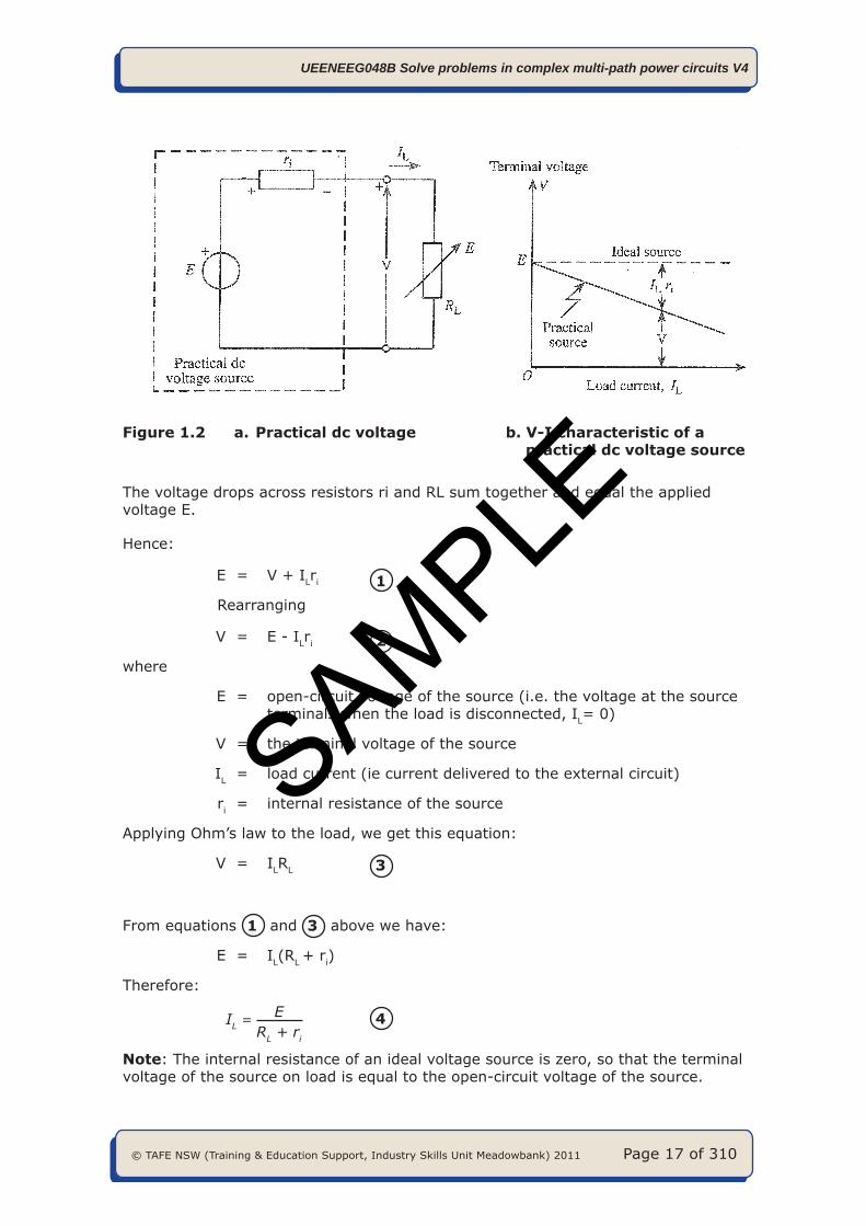
The model of a practical dc voltage source of E volts and internal resistance ri ohms is shown in Figure 1.2a below, with the box in broken lines representing such a source.
The V-I characteristic of a practical dc voltage source is shown in Figure 1.2b.
SAMPLE
© TAFE NSW (Training & Education Support, Industry Skills Unit Meadowbank) 2011 Page 17 of 310
UEENEEG048B Solve problems in complex multi-path power circuits V4
Figure 1.2 a. Practical dc voltage b. V-I characteristic of a practical dc voltage source
The voltage drops across resistors ri and RL sum together and equal the applied voltage E.
Hence:
E = V + ILri 1 Rearranging
V = E - ILri 2
where
E = open-circuit voltage of the source (i.e. the voltage at the source terminals when the load is disconnected, IL= 0)
V = the terminal voltage of the source
IL = load current (ie current delivered to the external circuit)
ri = internal resistance of the source
Applying Ohm’s law to the load, we get this equation:
V = ILRL 3
From equations 1 and 3 above we have:
E = IL(RL + ri)
Therefore:
IL = ERL + ri
4
Note: The internal resistance of an ideal voltage source is zero, so that the terminal voltage of the source on load is equal to the open-circuit voltage of the source.
SAMPLE
UEENEEG048B Solve problems in complex multi-path power circuits V4
© TAFE NSW (Training & Education Support, Industry Skills Unit Meadowbank) 2011 Page 18 of 310
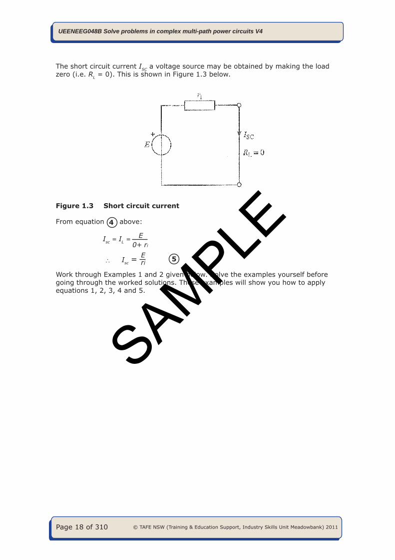
The short circuit current ISC a voltage source may be obtained by making the load zero (i.e. RL = 0). This is shown in Figure 1.3 below.
Figure 1.3 Short circuit current
From equation 4 above:
Isc = IL = E0+ ri
Isc = Eri 5
Work through Examples 1 and 2 given below. Solve the examples yourself before going through the worked solutions. These examples will show you how to apply equations 1, 2, 3, 4 and 5.
SAMPLE
© TAFE NSW (Training & Education Support, Industry Skills Unit Meadowbank) 2011 Page 19 of 310
UEENEEG048B Solve problems in complex multi-path power circuits V4
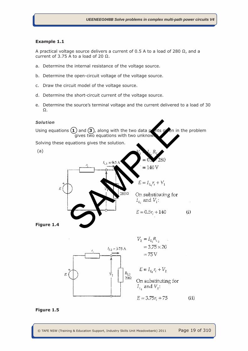
Example 1.1
A practical voltage source delivers a current of 0.5 A to a load of 280 Ω, and a current of 3.75 A to a load of 20 Ω.
a. Determine the internal resistance of the voltage source.
b. Determine the open-circuit voltage of the voltage source.
c. Draw the circuit model of the voltage source.
d. Determine the short-circuit current of the voltage source.
e. Determine the source’s terminal voltage and the current delivered to a load of 30 Ω.
Solution
Using equations 1 and 3 , along with the two data points given in the problem gives two equations with two unknowns.
Solving these equations gives the solution.
(a)
Ω
Figure 1.4
RL 2
Ω
Figure 1.5
SAMPLE