UEE3504: Introduction to Communication Systemsshannon.cm.nctu.edu.tw/comtheory/background.pdf · 1...
47
1 UEE3504: Introduction to Communication Systems Po-Ning Chen, Professor Dept. of Electrical and Computer Eng. National Chiao Tung University Background and Preview To give you a basic understanding of communications
Transcript of UEE3504: Introduction to Communication Systemsshannon.cm.nctu.edu.tw/comtheory/background.pdf · 1...

1
UEE3504: Introduction to Communication Systems
Po-Ning Chen, Professor Dept. of Electrical and Computer Eng. National Chiao Tung University
Background and Preview
To give you a basic understanding of communications

2
© Po-Ning [email protected] Background 3
Figure-1 Theory
o The next figure is always the “Figure 1” in every book regarding communications.
© Po-Ning [email protected] Background 4
Communications
o What is communication (or more specifically, communication engineering)? n The transmission of information from one point to
another through a succession of certain processes.

3
© Po-Ning [email protected] Background 5
Basic Elements Regard Communications
o Source of information n Voice, music, picture, or computer data
© Po-Ning [email protected] Background 6
Basic Elements Regard Communications
o Transmitter n Source → Source Symbol (i.e., Source Word)
o Symbolize the information from a source n Source Symbol → Code Word
o Encode the source symbol so that the other sources (i.e., noise and interfering signal) can hardly interfere the information transmission.
n Code Word → Channel Symbol (i.e., Transmitted Signals) o Modulate the code word into a form that is suitable for
transmission over the channel, which involves varying some parameter of a carrier wave in accordance with the message signal.

4
© Po-Ning [email protected] Background 7
Basic Elements Regard Communications
o Noise/Interference n Unwanted waves that tend to disturb the
transmission and processing of messages. n Could be internal or external to the system. n Could be additive or multiplicative (or both) to the
information-bearing signals.
© Po-Ning [email protected] Background 8
Basic Elements Regard Communications
o Receiver n Hard Decision
o Channel Symbol → Code Bit o Decode from Code Bits to Code Word o Code Word → Source Symbol → Source
n Soft Decision o Decode from Channel Symbol to Code Word o Code Word → Source Symbol → Source

5
© Po-Ning [email protected] Background 9
Example: Basic Elements Regard Communications
o Source = An alphabet “A”
© Po-Ning [email protected] Background 10
Example : Basic Elements Regard Communications
o Transmitter n Source “A” → Binary Source Symbol (01000001)
o Symbolize the information from a source n Source Symbol (01000001) → Code Word (000 111 000
000 000 000 000 111) o Encode the source symbol by the three-times repetition code
so that the other sources (i.e., noise and interfering signals) can hardly interfere the information transmission.
o 001, 010, 011, 100, 101, 110 are not code words. Hence, their appearance is possible only when noise is introduced.

6
© Po-Ning [email protected] Background 11
Example : Basic Elements Regard Communications
n Code Word (000 111 000 000 000 000 000 111) → Channel Symbol (000 555 000 000 000 000 000 555 ) o Modulate the code word into some channel-permissible
(physical-medium permissible) symbols.
n Due to Channel Interference, we receive: 010 442 222 033 011 020 032 434
© Po-Ning [email protected] Background 12
Example : Basic Elements Regard Communications
o Receiver n Hard Decision
o Channel Symbol 010 442 222 033 011 020 032 434 → Code Bit (Threshold 2.5) 000 110 000 011 000 000 010 111
o Decode from Code Bits to Code Word (Majority Rule) 000 111 000 111 000 000 000 111
o Code Word 000 111 000 111 000 000 000 111 → Source Symbol 01010001 → Source “Q”

7
© Po-Ning [email protected] Background 13
Example : Basic Elements Regard Communications
o Receiver n Soft Decision
o Decode from Channel Symbol 010 442 222 033 011 020 032 434 to (channel-symbolized) Code Word 000 555 000 000 000 000 000 555 n By finding the minimum distance to legitimate codewords
000 and 111. n E.g., d(033, 000) = (0-0)2+(3-0)2+(3-0)2 = 18 d(033, 555) = (0-5)2+(3-5)2+(3-5)2 = 33
o Code Word 000 111 000 000 000 000 000 111 → Source Symbol 01000001→ Source “A”
© Po-Ning [email protected] Background 14
Basic Modes of Communications o Broadcasting
n Often, uni-directional. n A single powerful transmitter to numerous
(inexpensive) receivers n Example. Radio and TV.
o Point-to-point communication n Often, bi-directional. n Two entities exchange information. n Example. Telephone.

8
© Po-Ning [email protected] Background 15
Feature of Communications
o Statistics n The source is statistical in nature. n The noise and interference are naturally random. n Principles of Communication Engineering: How to
design a communication system only based on the knowledge of the statistics of the source and interferences (without knowing exactly what the true source and interference are)?
© Po-Ning [email protected] Background 16
Feature of Communications o Example
n Source o We do not know if the next source symbol is 0 or 1. o But, we do know the probability of the next source
symbol being 0, and also, the probability of the next source symbol being 1.
n Noise/Interference o We do not know what value the noise/interference will
take? o But, we do know the noise is, say, Gaussian
distributed.

9
© Po-Ning [email protected] Background 17
Feature of Communications
o This is the reason why “Probabilities” (Chapter 1) is considered an important background to communication study.
© Po-Ning [email protected] Background 18
Primary Communication Resources
o Primary Communication Resources are something “known” at the design stage. n As aforementioned, source and noise/interference
are (often) something “unknown” at the design stage.

10
© Po-Ning [email protected] Background 19
Primary Communication Resources o Examples of Primary Communication Resources
n Transmission Power o Specifically, it’s the average power of the transmitted
signals. o A more useful measure than the absolute transmission
power is the signal-to noise (power) ratio (SNR), defined as the ratio of the average signal power to the average noise power. This quantity is often expressed in decibel (dB), which is defined as 10 log10(SNR).
n Channel Bandwidth o The band of frequencies for use of transmitting
messages.
© Po-Ning [email protected] Background 20
Primary Communication Resources
o Design principle of a communication system n How to efficiently use (usually in a tradeoff
fashion) the communication resources!

11
© Po-Ning [email protected] Background 21
Sources of Information
o “Sources” can sometimes be viewed as one kind of Communication Resources. n For example, there are systems designed
specifically for “exchanging voices.” n Such a system may not be apt to transmit computer
data. n This introduces the subjects of “Source-Specific
Communication.” n Next, we brief several sources commonly seen in
the literature.
© Po-Ning [email protected] Background 22
Sources of Information: (1) Speech
o Features n Voice spectrum extends well beyond 10kHz. n Most of the average power is concentrated in the
range of 100 to 600 Hz.
n A band of 300 to 3100 Hz gives good articulation. n The sound wave propagates through the air at a
speed of 300 meter/second.
Do Re Mi Fa So La Si Do 261.6 293.7 329.6 349.2 392.0 440 493.9 523 Freq (Hz)
Pitch Name

12
Schematic representation of the vocal system
© Po-Ning [email protected] Background 23
© Po-Ning [email protected] Background 24
Sources of Information: (1) Speech o The speech-production process may be viewed
as a form of filtering: n A sound source excites a vocal tract filter.
D
D
a1
a9
a10
+
Excitation Speech
+
+
+
Lips
Vocal Tract
Glottal Volume

13
© Po-Ning [email protected] Background 25
Sources of Information: Speech
o As the sound propagates along the vocal tract, the spectrum (i.e., frequency content) is shaped by the frequency selectivity of the vocal tract —a resonance phenomenon observed in organ pipe.
o So the hearing mechanism is (and should be) sensitive to frequency.
© Po-Ning [email protected] Background 26
Source of Information: Music o Originate from musical instruments, such as
piano, violin, and flute. o It consists of:
n Melody: A time sequence of sounds. n Harmony: A set of simultaneous sounds.
o Different from speech, the spectrum of a music source may extend up to about 15 KHz. n Accordingly, a much wider bandwidth resource is
demanded.

14
© Po-Ning [email protected] Background 27
Source of Information: Pictures
o Two dimensional information. o Classifications
n Dynamic pictures – Video, such as North American Audio TV (NAA-TV)
n Still pictures – Facsimile. o To transmit still picture over a telephone channel.
© Po-Ning [email protected] Background 28
Source of Information: NAA-TV o North American Analog TV
n 525 horizontal lines, decomposed into two 262.5 line interlaced fields (See the next slide.)
n Completion of each interlaced field takes 1/60 second o Horizontal line-scanning frequency is 262.5/(1/60) =
15.75 KHz. n Hence, 30 still pictures are shown per second. n The human “persistence of vision” phenomenon
will perceive these still pictures to be moving pictures.

15
© Po-Ning [email protected] Background 29
Source of Information: NAA-TV
Interlaced raster scan.
© Po-Ning [email protected] Background 30
Source of Information: NAA-TV n In the NTSC (National Television System
Committee) system, a total of 4.2 MHz bandwidth is demanded for TV transmission.

16
© Po-Ning [email protected] Background 31
Source of Information: Computer Data
o The first code developed specifically for computer communication (1967) – ASCII (American Standard Code for Information Interchange).
© Po-Ning [email protected] Background 32
Source of Information: Computer Data

17
© Po-Ning [email protected] Background 33
Source of Information: Computer Data
o ASCII (American Standard Code for Information Interchange)
n 7-bit code for alphabetic numerical characters n Bit 8 is sometimes used as parity-check bit or used
to form the extended ASCII code o Even parity: Total number of 1’s is even. o Odd parity: Total number of 1’s is odd.
n Extended ASCII code can be displayed but cannot necessarily be printed out.
Bit originates from “Binary Digit.”
© Po-Ning [email protected] Background 34
Source of Information: Computer Data
o Since ASCII is defined for communication, it also includes some symbols for communication purpose such as n ENQ (enquiry) – 05X n ETB (end of transmission block) – 17X

18
© Po-Ning [email protected] Background 35
Source of Information: Computer Data
o RS (Recommended Standard) -232 Transmission n Synchronous n Asynchronous
© Po-Ning [email protected] Background 36
Source of Information: Computer Data
o Asynchronous Serial Data n No clock or timing signal required. n ST : start bit n S : stop bit n P : parity bit n D6~D0 : data bits (often, exact one ASCII character) n Usually, 10 bit frame with even-parity/7-data-bit or
no-parity/8-data-bit.
S ST D0 D1 D2 D3 D4 D5 D6 P S ST D0 D1 D2 D3 D4 D5 D6 P S
frame
19
© Po-Ning [email protected] Background 37
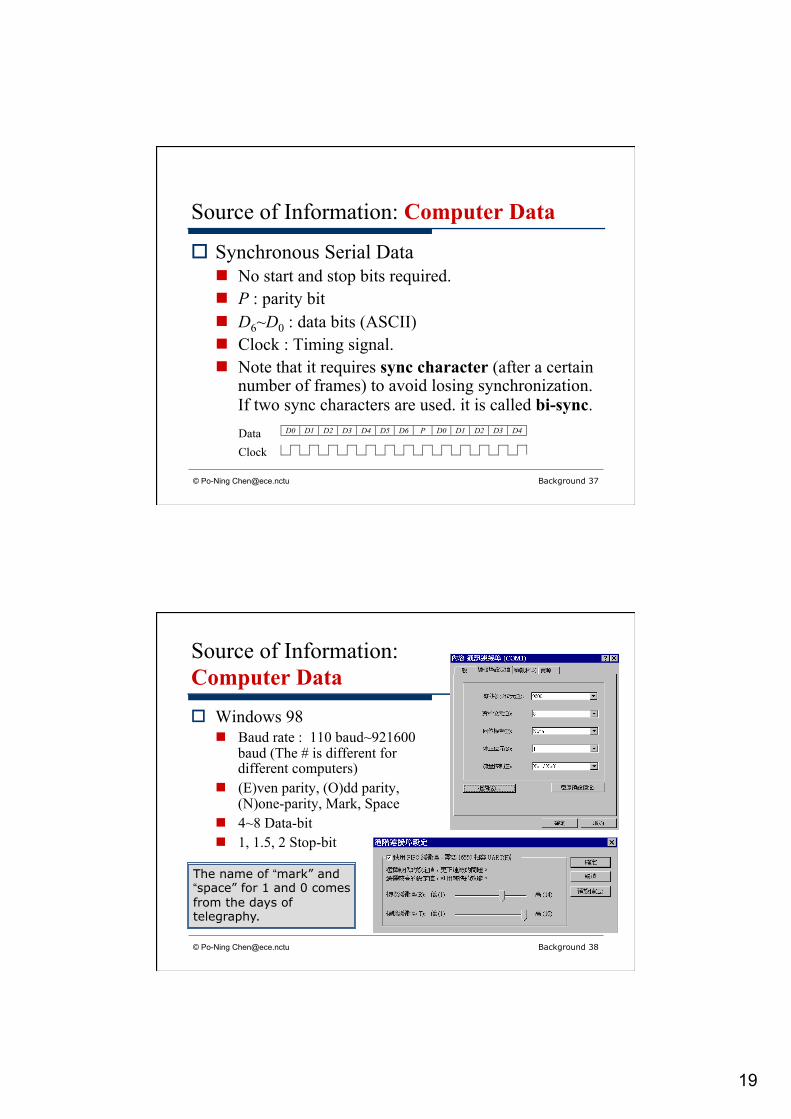
Source of Information: Computer Data
o Synchronous Serial Data n No start and stop bits required. n P : parity bit n D6~D0 : data bits (ASCII) n Clock : Timing signal. n Note that it requires sync character (after a certain
number of frames) to avoid losing synchronization. If two sync characters are used. it is called bi-sync.
D0 D1 D2 D3 D4 D5 D6 P D0 D1 D2 D3 D4Data Clock
© Po-Ning [email protected] Background 38
Source of Information: Computer Data
o Windows 98 n Baud rate : 110 baud~921600
baud (The # is different for different computers)
n (E)ven parity, (O)dd parity, (N)one-parity, Mark, Space
n 4~8 Data-bit n 1, 1.5, 2 Stop-bit
The name of “mark” and “space” for 1 and 0 comes from the days of telegraphy.

20
© Po-Ning [email protected] Background 39
Source of Information: Computer Data
© Po-Ning [email protected] Background 40
Source of Information: Computer Data

21
© Po-Ning [email protected] Background 41
Source of Information: Computer Data
o The computer data stream so formed is then applied to a device called a modem (modulator-demodulator).
o Unlike source traffic from speech or video, the computer data is often bursty rather than continuous.
© Po-Ning [email protected] Background 42
Missed Part of Figure-1 in Textbook
o Source before entering the transmitter is often compressed (in order to save time or space).
o This part is missing in Figure 1 of the textbook.
22
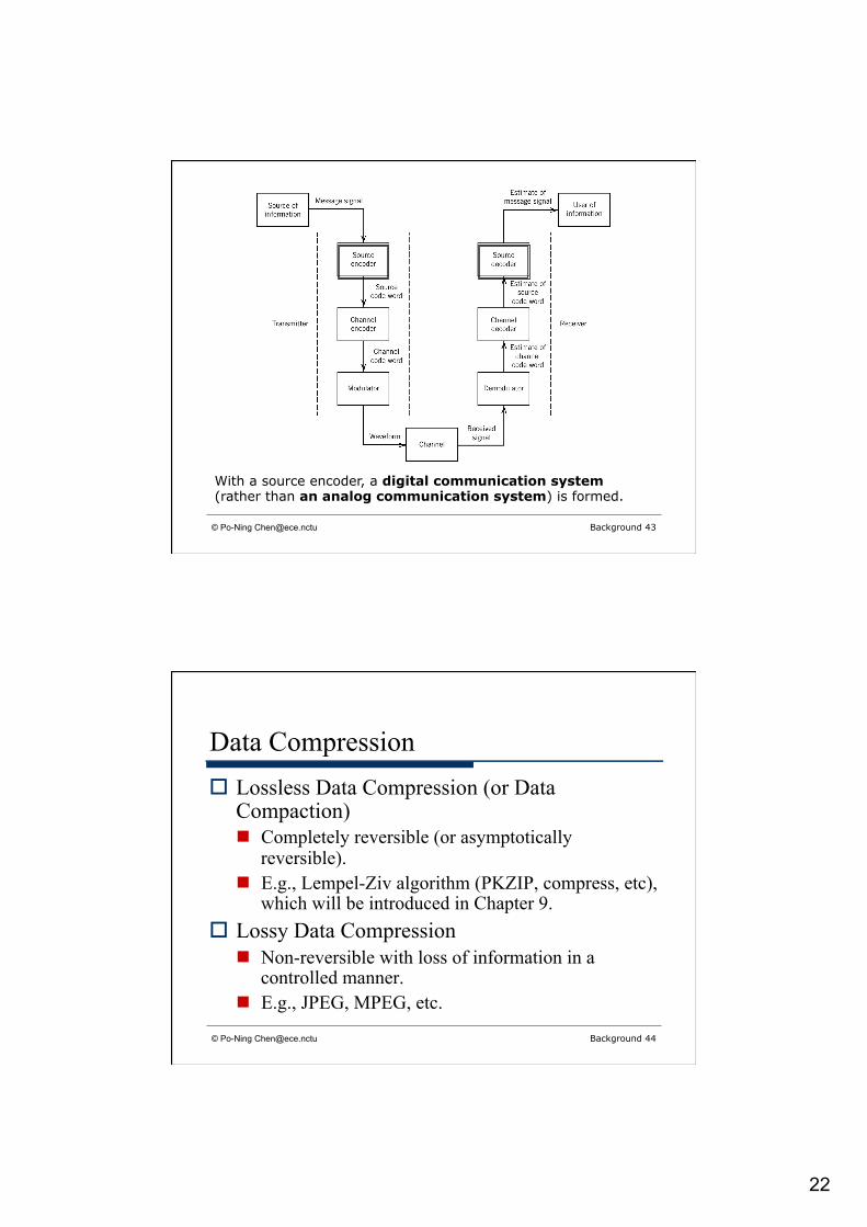
© Po-Ning [email protected] Background 43
With a source encoder, a digital communication system (rather than an analog communication system) is formed.
© Po-Ning [email protected] Background 44
Data Compression o Lossless Data Compression (or Data
Compaction) n Completely reversible (or asymptotically
reversible). n E.g., Lempel-Ziv algorithm (PKZIP, compress, etc),
which will be introduced in Chapter 9. o Lossy Data Compression
n Non-reversible with loss of information in a controlled manner.
n E.g., JPEG, MPEG, etc.
23
© Po-Ning [email protected] Background 45
Lossy Data Compression for Images
o JPEG (Joint Photographic Experts Group) n An image coding standard n Pixels are grouped in 8-by-8 block. n DCT (discrete cosine transform) is then applied to
each block. n Quantize each of the 64 DCT coefficients according
to a pre-specified table. n Huffman-encode (introduced in Chapter 9) the
quantization results.
© Po-Ning [email protected] Background 46
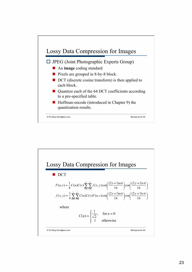
Lossy Data Compression for Images n DCT
∑∑
∑∑
= =
= =
⎟⎠
⎞⎜⎝
⎛ +⎟⎠
⎞⎜⎝
⎛ +=
⎟⎠
⎞⎜⎝
⎛ +⎟⎠
⎞⎜⎝
⎛ +=
7
0
7
0
7
0
7
0
16)12(cos
16)12(cos),()()(
41),(
16)12(cos
16)12(cos),()()(
41),(
u v
x y
vyuxvuFvCuCyxf
vyuxyxfvCuCvuF
ππ
ππ
where
⎪⎩
⎪⎨⎧ =
=otherwise1
0for ,2
1)( uuC
24
© Po-Ning [email protected] Background 47
Lossy Data Compression for Video
o MPEG-1 (Motion Photographic Experts Group) video coding standard n A video coding standard primarily for 30 fps
(frames per second) video n Result in a bit-stream rate of 1.5 megabits per
second
© Po-Ning [email protected] Background 48
Lossy Data Compression for Video n Design objective : To reduce four kinds of
redundancies: o Interframe (temporal) redundancy
n Its reduction is achieved through the use of prediction to estimate each frame from its neighbors.
n The resulting prediction error is transmitted for motion estimation and compensation.
o Interpixel redundancy within a frame o Psychovisual redundancy o Entropic coding redundancy

25
© Po-Ning [email protected] Background 49
Lossy Data Compression for Video n As with JPEG, the last three redundancies are
reduced through the combined use of DCT, quantization and lossless entropic coding.
© Po-Ning [email protected] Background 50
Lossy Data Compression for Audio
o MPEG-1 audio coding standard n A perceptual (waveform) coder, as contrary to a
vocoder o The amplitude-time waveform of the decoded audio
signal closely approximates that of the original audio signal.
26
© Po-Ning [email protected] Background 51
Lossy Data Compression for Audio n Encoding process
o Time-Frequency Mapping (sub-band decomposition) o Psychoacoustic modeling (operates according to the
psychoacoustic behavior of the human auditory system)
o Quantization and coding o Frame-packing (format the quantized audio samples
into a decodable bit stream)
© Po-Ning [email protected] Background 52
Lossy Data Compression for Audio n Why Psychoacoustic modeling?
o Human ears have a perceptual phenomenon known as auditory masking.
o Specifically, the human ear does not perceive quantization noise in a given frequency band if the average noise power lies below the masking threshold
o The masking threshold varies with frequency across the band.
o Hence, a perceptual weighting filter is applied to waveforms before quantization.

27
© Po-Ning [email protected] Background 53
o OSI
OSI (Open System Interconnection) model; the acronym DLC in the middle of the figure stands for data link control.
© Po-Ning [email protected] Background 54
Communication Networks
o OSI reference model was developed by ISO (International Organization for Standardization) in 1977.
o Figure 1 only concerns PHY layer. o Now we take a quick look of its relation with
higher layers, such as Network layers.

28
© Po-Ning [email protected] Background 55
Communication Networks
Network Layer : Routers
© Po-Ning [email protected] Background 56
Communication Networks
o Routing mechanisms n Circuit Switching
o Uninterrupted, exclusively use of links o E.g., Telephone.
n Packet Switching o Shared-on-demand links

29
© Po-Ning [email protected] Background 57
Communication Networks
o Why OSI reference model? n Each layer can perform its related subset of
primitive functions without knowing the implementation details of the next lower layer.
n The adjacent layers communicate through well-defined interfaces, which defines the services offered by the lower layer to the upper layer.
© Po-Ning [email protected] Background 58
Communication Networks o The entities that comprise the corresponding
layers on different systems are referred to as peer processes.
o Two peer entities then communicate through a well-defined set of rules of procedures, named Protocol.
o Again, this text/course primarily considers PHY layer.

30
© Po-Ning [email protected] Background 59
Internet
o Internet – A special communication network, as contrary to an Intranet.
o Features of Internet n Applications are carried out independently of the
technology employed to construct the network. n The network technology is capable of evolving
without affecting the applications.
© Po-Ning [email protected] Background 60
Internet
o Architecture of Internet
Direct Data Exchange
Cross-Router Data Exchange

31
© Po-Ning [email protected] Background 61
Internet Protocol (IP)
© Po-Ning [email protected] Background 62
Internet Service
o Internet Service is “Best Effort” in nature. o As a consequence, no guarantees of timely
transmission, and even delivery.
32
© Po-Ning [email protected] Background 63
Communication Channels
o Channels, where the noise/interference resides, can be roughly divided into two groups: n Guided propagation channels
o E.g., telephone channels, coaxial cables, and optical fibers
n Free propagation channels o E.g., broadcast channels, mobile radio channels, and
satellite channels
© Po-Ning [email protected] Background 64
Communication Channels: (i) Telephone Channel
o Features of telephone channel n A channel performs “voice → electrical signal →
sound” n Band-limited channel
o A speech signal (male or female) is essentially limited to a band from 300 to 3100 Hz.

33
© Po-Ning [email protected] Background 65
Communication Channels: (i) Telephone Channel
o Measures used in characterizing channel n Insertion loss = 10 log10 (P0/PL) dB
o PL = power delivered to a load from a source via the channel o P0 = power delivered to the same source not via the channel
PL
P0
Channel
© Po-Ning [email protected] Background 66
Communication Channels: (i) Telephone Channel
n Envelope delay o The negative of the derivative of the phase response with
respect to the angular frequency ω = 2πf. o Example. Envelope delay = a for the next channel.
fajefH π2)( −=)(tg )( atg −
)].(exp[|)(|)( fjfHfH β=The phase response of a channel filter H(f) is β(f), where

34
© Po-Ning [email protected] Background 67
Communication Channels: (i) Telephone Channel
Insertion Loss Envelope Delay
© Po-Ning [email protected] Background 68
Communication Channels: (ii) Coaxial Cable
o A coaxial cable offers a greater degree of immunity to electromagnetic interference (EMI), and a much higher bandwidth than twisted pair telephone lines.
o Example of its applications n Local area network in an office environment n Cable television

35
© Po-Ning [email protected] Background 69
Communication Channels: (iii) Optical Fiber
o Features n Enormous potential bandwidth
o The bandwidth is roughly equal to 10% of the carrier frequency (2 × 10¹⁴ Hz).
o Notably, the transmission attainable limit (for additive white Gaussian noise with SNR=10dB) is around
secondper Gigabit 86.6918secondper bit 1091886.6
)101(log)102()1(log
13
10/102
13
2
=
×=
+×=
+=dB
SNRBC
© Po-Ning [email protected] Background 70
Communication Channels: (iii) Optical Fiber
n Low transmission loss o 0.1dB/km
n Immunity to EMI n Small size and weight (thinner than human hair) n Ruggedness and flexibility
o Possibility of being bent or twisted without damage
36
© Po-Ning [email protected] Background 71
Communication Channels: (iv) Wireless Broadcast Channels
o Transmission n Up-convert the modulated baseband information-
bearing signal to Radio Frequency (RF) passband signal
n Transmit the RF passband signal via antenna o Reception
n Pick up the radiated waves by an antenna. n Down-convert the received passband signal to
baseband signal (perhaps through an intermediate step called the intermediate frequency (IF) band).
© Po-Ning [email protected] Background 72
Communication Channels: (v) Mobile Radio Channels
o The main difference between this channel and the previous channel is the consideration of mobility. n Due to mobility, there is no “line-of-sight” path for
communication; n rather, radio propagation takes place mainly by way
of scattering from the surfaces of the surrounding buildings and by diffraction over and around them.
n This results in a multipath fading transmission.
37
© Po-Ning [email protected] Background 73
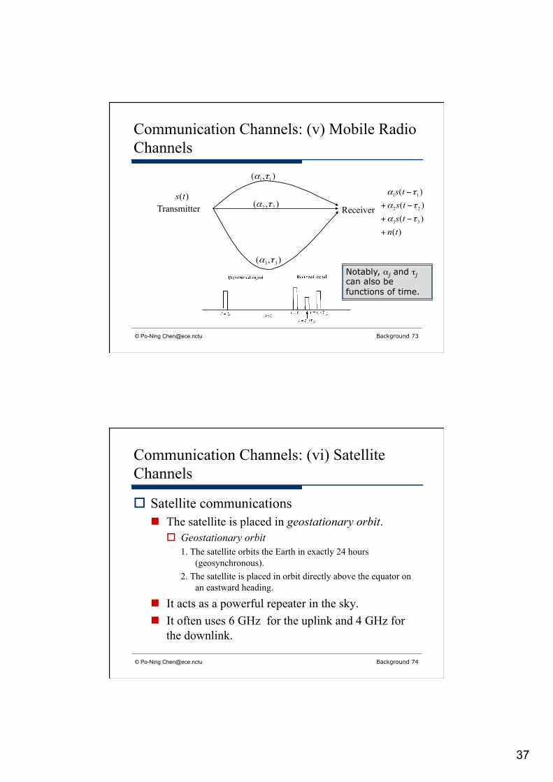
Communication Channels: (v) Mobile Radio Channels
Transmitter Receiver
),( 11 τα
),( 22 τα
),( 33 τα
)()()()(
33
22
11
tntststs
+
−+
−+
−
τα
τα
τα)(ts
Notably, αj and τj can also be functions of time.
© Po-Ning [email protected] Background 74
Communication Channels: (vi) Satellite Channels
o Satellite communications n The satellite is placed in geostationary orbit.
o Geostationary orbit 1. The satellite orbits the Earth in exactly 24 hours
(geosynchronous). 2. The satellite is placed in orbit directly above the equator on
an eastward heading.
n It acts as a powerful repeater in the sky. n It often uses 6 GHz for the uplink and 4 GHz for
the downlink.

38
© Po-Ning [email protected] Background 75
Communication Channels: (vi) Satellite Channels
n The 6/4-GHz band offers the following attributes: 1. Relatively inexpensive microwave equipment 2. Low attenuation due to rainfall
n Rainfall is a primary atmospheric cause of signal loss. 3. Insignificant sky background noise
n The sky background noise due to random noise emissions from galactic, solar and terrestrial sources reaches its lowest level between 1 and 10 GHz.
© Po-Ning [email protected] Background 76
Communication Channels: (vi) Satellite Channels
n A typical satellite in the 6/4-GHz band is assigned a 500 MHz bandwidth, which is divided among 12 transponders. o Each transponder can carry at least one color television
signal, 1200 voice circuits, or digital data at a rate of 50 Mb/s.

39
© Po-Ning [email protected] Background 77
Classifications of Communication Channels (according to the natures or resources)
o Linear or non-linear n A wireless radio channel is linear whereas a satellite
channel is usually non-linear. o Time invariant or time varying
n An optical fiber is time invariant, whereas a mobile radio channel is typically time varying.
o Band limited or power limited n A telephone channel is band limited, whereas an
optical fiber link and a satellite channel are both power limited.
© Po-Ning [email protected] Background 78
Classification of Modulation Process
o Continuous-wave modulation n A sinusoidal wave is used as the carrier. n It can be further classified as:
o Amplitude modulation (AM) : Amplitude of the carrier is varied in accordance with the message.
o Frequency modulation (FM) : Frequency of the carrier is varied in accordance with the message.
o Phase modulation (PM) : Phase of the carrier is varied in accordance with the message.

40
© Po-Ning [email protected] Background 79
Classification of Modulation Process
o Pulse modulation n The carrier consists of a sequence of rectangular
pulses. n It can be sub-divided to:
o Analog pulse modulation o Digital pulse modulation
© Po-Ning [email protected] Background 80
Classification of Modulation Process n Analog pulse modulation
o Pulse-amplitude modulation (PAM), pulse-duration modulation (PDM), pulse-position modulation (PPM)
o The amplitude, duration, position of the pulses varies in accordance with the message signals.
n Digital pulse modulation o Pulse-code modulation (PCM)
41
© Po-Ning [email protected] Background 81
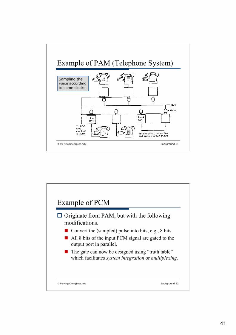
Example of PAM (Telephone System)
Sampling the voice according to some clocks.
© Po-Ning [email protected] Background 82
Example of PCM
o Originate from PAM, but with the following modifications. n Convert the (sampled) pulse into bits, e.g., 8 bits. n All 8 bits of the input PCM signal are gated to the
output port in parallel. n The gate can now be designed using “truth table”
which facilitates system integration or multiplexing.

42
© Po-Ning [email protected] Background 83
What is multiplexing?
o To combine (several modulated) signals for their simultaneous (or concurrent) transmission. n Frequency-division multiplexing (FDM) n Time-division multiplexing (TDM) n Code-division multiplexing (CDM) n Wavelength-division multiplexing (WDM),
specifically for use of optical fibers. o Some treats WDM as a special case of FDM, since c =
f λ.
© Po-Ning [email protected] Background 84
Shannon’s Information Capacity Theorem
o The underlying limit for digital communications

43
© Po-Ning [email protected] Background 85
Transmission Rate = Source code bit per second (Information bit per second)
© Po-Ning [email protected] Background 86
Shannon’s Information Capacity Theorem
o Reliable transmission rate (for pre-specified modulator, channel and demodulator). n The rate for which a proper design of channel
encoder-decode pair can fulfill arbitrarily small error requirement.
o Shannon finds the general formula for the largest reliable transmission rate, which he baptized as “(coding) channel capacity.”
44
© Po-Ning [email protected] Background 87
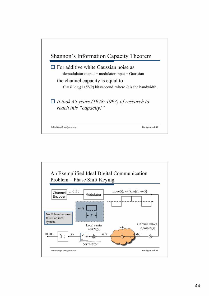
Shannon’s Information Capacity Theorem
o For additive white Gaussian noise as demodulator output = modulator input + Gaussian
the channel capacity is equal to C = B log2(1+SNR) bits/second, where B is the bandwidth.
o It took 45 years (1948~1993) of research to reach this “capacity!”
© Po-Ning [email protected] Background 88
An Exemplified Ideal Digital Communication Problem – Phase Shift Keying
Channel Encoder
…0110 Modulator
…,-m(t), m(t), m(t), -m(t)
m(t)
T
⊗
Carrier wave Accos(2πfct)
s(t) ⊕
w(t)
x(t) ⊗
Local carrier cos(2πfct)
∫Tdt
0
correlator
yT > < 0 0110…
No IF here because this is an ideal system.

45
© Po-Ning [email protected] Background 89
An Exemplified Ideal Digital Communication Problem – Phase Shift Keying
o Assume that the local carrier (at the receiver end) is exactly the same as the transmitter carrier.
o Assume that the correlator is completely synchronized with the transmitter. n So the integration inside correlator covers a
complete message signal m(t). In other words, it will not happen that the integration inside correlator covers 80% of the current m(t) but 20% of the previous m(t).
yT = x(t)cos(2π fct)dt0
T∫
= [s(t)+w(t)]cos(2π fct)dt0
T∫
= [±Ac cos(2π fct)+w(t)]cos(2π fct)dt0
T∫
= ±Ac cos2(2π fct)dt0
T∫ + w(t)cos(2π fct)dt0
T∫
= ±Ac1+ cos(4π fct)
2dt
0
T∫ + w(t)cos(2π fct)dt0
T∫
= ±12AcT ±
12Ac cos(4π fct)dt0
T∫ + w(t)cos(2π fct)dt0
T∫
= ±12AcT + w(t)cos(2π fct)dt0
T∫
© Po-Ning [email protected] Background 90
(By assuming that fc is a multiple of 1/T.)

46
© Po-Ning [email protected] Background 91
An Exemplified Ideal Digital Communication Problem – Phase Shift Keying
o Some interesting issues to consider: n What if the local carrier does not equal the
transmitter carrier.
n What if fc is not a multiple of 1/T. n What if the receiver does not synchronize with the
transmitter? n What is the BER of this system?
yT = [±Ac cos(2π ftct)+w(t)]cos(2π frct)dt0
T∫
© Po-Ning [email protected] Background 92
An Exemplified Ideal Digital Communication Problem – Phase Shift Keying
n Is the correlator receiver optimal in the sense of BER?
n Is the “sign-decision” optimal in the sense of BER? n Is the above combination optimal in the sense of
BER? n Is the BER robust for imperfect system, such as
timing and carrier mismatch? n Is the rectangular m(t) a fine choice? Moreover, is
PSK a fine choice? If affirmative, in what sense? n ….
47
© Po-Ning [email protected] Background 93
An Exemplified Ideal Digital Communication Problem – Phase Shift Keying
o All these problems will be hopefully answered in this course (and subsequent courses).


![Problemsforthe10thQuiz Name: StudentID: Scoreshannon.cm.nctu.edu.tw/comtheory/quiz10_solution18fall.pdfComparator Sampled eq One-bit message signal quantizer m[n] eq n — 1] Accumulator](https://static.fdocuments.us/doc/165x107/5ea80ae5cabaf33ea6284ffa/problemsforthe10thquiz-name-studentid-comparator-sampled-eq-one-bit-message-signal.jpg)