
UDC 691 . 714 Development of “ Nittetsu-Super-Frame ... · Fig. 2 2×4 wooden frame and...
13
NIPPON STEEL TECHNICAL REPORT No. 97 JANUARY 2008 - 82 - UDC 691 . 714 Development of “ Nittetsu-Super-Frame ® ” System and Expanding Its Market—Challenge to Enlarge the Possibility of Light-Gauge Steel-Framed Houses in the Low-Rise Building Market— Hiroaki KAWAKAMI* 1 Yoshimitsu MURAHASHI* 2 Shigeaki TOHNAI* 1 Tomohisa HIRAKAWA* 1 Hiroyuki KAIBARA* 1 Kazunori FUJIHASHI* 1 Yoshimichi KAWAI* 3 Hiroshi TANAKA* 3 Abstract On Nov. 15th, 2000, light-gauge steel framed houses were legislated under a Build- ing Standard Law in Japan as a new structural system. This system is used for light- gauge steel sections that are galvanized and a thickness of 1mm on average. The structural frame has a high potential for application to low-rise buildings. Initially, this paper introduces the history of development for steel framed houses, tackled by major steel companies in Japan on the domain of housing. Secondly, it describes the development situation of “Nittetsu-Super-Frame” as our original system that was aimed to enlarge the market and enabled construction of three stories houses hav- ing a one hour fire resistance performance, in addition to efforts for securing sev- eral types of performance, for example, sound reduction and thermal environment. In addition, advantages on global warming of “Nittetsu-Super-Frame” are also dis- cussed. * 1 Construction & Architectural Materials Development & Engineering Service Div. (Concurrently Serving as Manager of Flat Products Sales Div.) 1. Introduction The steel frame construction method differs from the wood frame construction method in that it uses cold-formed galvanized shaped steel about 1.0 mm in thickness (Photo 1) in place of two-by-four wooden frame members. This method has already been put into prac- tical use in more than ten countries, including Japan, the United States, Australia and several countries in Europe. Today, it is one of the construction methods attracting the most attention in the world. 1) In this paper, we shall first review the birth of the steel frame construction method and the efforts of Japan’s major steelmakers to * 2 Construction & Architectural Materials Development & Engineering Service Div. * 3 Steel Research Laboratories develop this method. We shall then describe the Nittetsu Super Frame method that Nippon Steel developed for itself with the aim of pro- Photo 1 Light-gauge steel shapes and steel framed house
Transcript of UDC 691 . 714 Development of “ Nittetsu-Super-Frame ... · Fig. 2 2×4 wooden frame and...

NIPPON STEEL TECHNICAL REPORT No. 97 JANUARY 2008
- 82 -
UDC 691 . 714
Development of “ Nittetsu-Super-Frame® ” System and ExpandingIts Market—Challenge to Enlarge the Possibility of Light-Gauge
Steel-Framed Houses in the Low-Rise Building Market—Hiroaki KAWAKAMI*1 Yoshimitsu MURAHASHI*2
Shigeaki TOHNAI*1 Tomohisa HIRAKAWA*1
Hiroyuki KAIBARA*1 Kazunori FUJIHASHI*1
Yoshimichi KAWAI*3 Hiroshi TANAKA*3
Abstract
On Nov. 15th, 2000, light-gauge steel framed houses were legislated under a Build-
ing Standard Law in Japan as a new structural system. This system is used for light-
gauge steel sections that are galvanized and a thickness of 1mm on average. The
structural frame has a high potential for application to low-rise buildings. Initially,
this paper introduces the history of development for steel framed houses, tackled by
major steel companies in Japan on the domain of housing. Secondly, it describes the
development situation of “Nittetsu-Super-Frame” as our original system that was
aimed to enlarge the market and enabled construction of three stories houses hav-
ing a one hour fire resistance performance, in addition to efforts for securing sev-
eral types of performance, for example, sound reduction and thermal environment.
In addition, advantages on global warming of “Nittetsu-Super-Frame” are also dis-
cussed.
*1 Construction & Architectural Materials Development & EngineeringService Div. (Concurrently Serving as Manager of Flat Products SalesDiv.)
1. IntroductionThe steel frame construction method differs from the wood frame
construction method in that it uses cold-formed galvanized shapedsteel about 1.0 mm in thickness (Photo 1) in place of two-by-fourwooden frame members. This method has already been put into prac-tical use in more than ten countries, including Japan, the United States,Australia and several countries in Europe. Today, it is one of theconstruction methods attracting the most attention in the world.1)
In this paper, we shall first review the birth of the steel frameconstruction method and the efforts of Japan’s major steelmakers to
*2 Construction & Architectural Materials Development & EngineeringService Div.
*3 Steel Research Laboratories
develop this method. We shall then describe the Nittetsu Super Framemethod that Nippon Steel developed for itself with the aim of pro-
Photo 1 Light-gauge steel shapes and steel framed house

NIPPON STEEL TECHNICAL REPORT No. 97 JANUARY 2008
- 83 -
moting application of the steel frame construction method to low-rise buildings – specifically the structure of the Nittetsu Super Frameand the company’s activities to secure the performance required fordwellings, such as fire resistance, thermal insulation and sound insu-lation – and discuss the advantages of the Nittetsu Super Frame fromthe standpoint of addressing the deteriorating state of global warm-ing.
This paper was compiled from various papers which had alreadybeen published by the Iron and Steel Institute of Japan,1) the Korea-China-Japan Association for Structural Steel Construction,2) the Ar-chitectural Institute of Japan,3-5) and the Japan Association for FireScience and Engineering.6)
2. Birth and Characteristics of the Steel Frame Con-struction Method
2.1 Birth of the steel frame construction methodThe first historical step toward the development of the steel frame
construction method in Japan was marked in November 1994 whenit was taken up as one of the themes of a meeting of the Urban SteelSociety (Chairman: Masayoshi Igarashi, professor emeritus at OsakaUniversity) sponsored by the Iron and Steel Production Division ofthe Basic Industries Bureau under the Ministry of International Tradeand Industry. The development history of the method and enactmentof related laws is shown in Table 1.
Of some 50,000 temporary houses constructed in the wake of theGreat Hanshin Earthquake that occurred in January, 1995, importedsteel-framed houses accounted for about 3,000. After the disaster, agood number of applications for official approval for construction ofsteel-framed houses in Japan came from abroad. Under those condi-tions, the Ministry of Construction announced in July of the same
year its “Standards for Rating & Evaluation of Performance of Steel-Framed Houses” through the Building Center of Japan. As a result, itbecame possible to construct steel-framed houses in Japan with thespecial approval of the Minister of Construction (Article 38 of theformer Building Standards Law). Then, in January 1996, Japan’s sixmajor steelmakers (Kawasaki Steel, Kobe Steel, Nippon Steel,Sumitomo Metal Industries, Nissin Steel and Nippon Kokan) set upa Steel-Framed House Committee with the Kozai Club (now the Ironand Steel Institute of Japan) as its secretariat, and launched earneststudies into the structural performance, fire resistance, durability,thermal insulation and sound insulation of steel-framed houses.
In 2000, full-scale marketing of detached houses built using thesteel frame construction method of the Kozai Club (KC) type began.Application of the KC-type method expanded to studio apartmentsin 2001. As a result, market recognition of the method rose mark-edly. In November, 2001, with the Ministry of Land, Infrastructure
1995
1996199719981999
2000
2001
2002
2003
2004
2005
2006
2007
The Great Hanshin EarthquakeStandards announced for Rating & Evaluating Steel-Framed Houses.Kozai Club (KC) establishes Steel-Framed House Committee.KC obtains approval of the Minister of Construction based on Article 38 of the former Building Standards Law.KC-type develops steel-framed houses.
Enactment of Japan’s Housing Quality Assurance ActRevision of The Building Standards Law [providing for detailed performance requirements]Revision of the provisions of Article 38 pertaining to KC-type steel-framed houses.Notification issued on light-gauge steel-framed houses.[Steel-framed houses officially recognized as a type of steel frame construction.]Article 1-3 of the Enforcement Regulations provides for the approval of the Minister of Construction for KC-type steel-framedhouses.Revision of the Building Standards Law [24-hour ventilation]First structural rating of Nittetsu Super Frame[Design allowing for fire-resistant structures/3-storied houses]Development of market for Nittetsu Super Frame begins in earnestSecond structural rating of Nittetsu Super Frame[Securing structural continuity, providing high-stiffness hardware, and improving effectiveness of spandrel and flap walls wereadded.]Third structural rating of Nittetsu Super Frame[Reinforcing load-bearing wall and joint hardware, clarifying design rules and establishment of more stringent design rules]Revision of the Building Standards Law [more stringent structural design, examinations and inspections]Article 1-3 of the Enforcement Regulations provides for the approval of the Minister of Construction for the Nittetsu SuperFrame method
Table 1 History of development and Laws fixed for steel framed houses
Fig. 1 Expansion in number of steel framed houses constructed in Japan
Num
ber
of s
teel
-fra
med
hou
ses
cons
truc
ted

NIPPON STEEL TECHNICAL REPORT No. 97 JANUARY 2008
- 84 -
and Transport’s issuance of a notification titled “Technical Standardsfor Ensuring the Safety of Methods of Construction of Light-GaugeSteel-Framed Structures or Structural Components,” steel-framedhouses were officially recognized as one type of steel frame con-struction under the Building Standards Law. As shown in Fig. 1, thenumber of steel-framed houses constructed in Japan has been steadilyincreasing. In the most recent year on record (2005), the total was2,157 (about 20,000 units).2.2 Characteristics of the steel frame construction method
The two-by-four wood frame construction method is a traditionalmethod of building houses in North America. Initially, frames aremade from wooden members, the cross section of which measures 2inches × 4 inches. (These are the dimensions before lumbering. Ac-tually, they are 38 mm × 89 mm.) Then, as shown in Fig. 2, a board(plywood, etc.) is nailed onto each of the frames to fabricate walland floor panels, which are assembled into a boxlike structure. InJapan, this method is widely known as the two-by-four method.
The steel frame construction method uses galvanized shaped steelabout 1 mm in thickness in place of wooden frame members. Sincethe shaped steel is that thin, it is possible to use drilling tapping screws,rather than nails, to joint structural members together without drill-ing screw holes beforehand (see Photo 2). In addition, the shapedsteel can easily be cut using an electric rotary saw or shears. Further-more, since the shaped steel is made from galvanized sheet, thanksto the sacrificial corrosion of the zinc plating, it is unnecessary toapply a protective coating (e.g., zinc-enriched paint) to the cut facesand joints. Thus, the light-gauge shaped steel is more like wood thansteel. It may be said, therefore, that ordinary engineering firms canuse the steel frame construction method in the same way as the two-by-four method.2)
The appearance of a typical exterior wall and the wall construc-tion of a steel-framed house are shown in Fig. 3. On the external sideof the house, a layer of thermal-insulating material and a ventilationlayer are provided, which, together with light-gauge shaped steel,completely cover the entire house space, with the exterior wall as acovering material. On the internal side, gypsum board is used as thecovering material. These structural members, facing board and cov-ering materials work in combination to perform the functions re-quired of dwelling houses, such as structural safety, fire resistance,thermal insulation and sound insulation. This is one of the salientcharacteristics of steel-framed houses.
3. Development and Application of KC-type Steel-framed HouseFacing boards applicable to KC-type steel-framed houses are lim-
ited to wood-based ones—plywood for structures, medium-densityboard, or particleboard (chipboard). By using those facing boards,the approval of the Minister of Construction (Article 38 of the formerBuilding Standards Law) for KC-type steel-framed houses was ob-tained in 2000 for detached houses up to three stories (including thosewith a shop on the first floor), row houses, two-storied semidetachedhouses and apartment buildings and for three-storied detached housesof mixed construction (reinforced concrete (RC) rigid-frame con-struction or box-frame construction for the first floor and steel frameconstruction for the second and third floors) (includes those having ashop on the first floor). As a result, it became possible to constructKC-type steel-framed houses by performing the simplified structuralcalculation process and applying for building permission as long asthey fall within the scope of the above approval.
Following the 2001 Notification, the six steelmakers newly ob-tained the approval of the Minister of Land, Infrastructure and Trans-port for “KC-type steel-framed houses” based on the “Approval foromission of structural calculation documents” provided for in Item 1of Article 1-3 of the Building Standards Law Enforcement Regula-tions, so that they could construct KC-type steel-framed houses sim-ply by performing simplified structural calculations and applyingfor building permission as before. It should be noted, however, thatthe above approval was valid only for one-story houses and two-story houses with or without cricket and that three-storied houseswere completely excluded from the scope of approval.
When it comes to constructing a KC-type steel-framed house, itis necessary first to join the Steel House Society and be registered asa member and then to receive technical training in design (see Fig.4), work execution, etc. provided by the Society. When applying forbuilding permission, it is necessary to obtain from the Society a cer-tificate for the KC-type steel-framed house, a certificate of approvalPhoto 2 Scene of joining with drilling tapping screws
Light-gauge galvanized shaped steel
Nail
Plywood, etc.
4 in
ches
2 inches
Thickness about 1 mm
Fig. 2 2××××× 4 wooden frame and light-gauge steel shapes
Internal side
Gypsum board
Covering material
Hollow layer
Through-screw
Light-gauge shaped steel
Structural member
Facing board
Thermal-insulating
material
Covering material
Ventilation layer
Furring strip
External side
Exterior wall
Fig. 3 Exterior wall structure of steel framed houses

NIPPON STEEL TECHNICAL REPORT No. 97 JANUARY 2008
- 85 -
for fire resistance, the design specification and the structural calcu-lation check sheet and to prepare the necessary documents for appli-cations. In addition, prior to construction of a steel-framed house,notification of construction work must be submitted to the Society.
4. Development of the Nittetsu Super Frame Methodand Response to Mandatory Indication of HousePerformance
4.1 Circumstances leading to developmentTable 2 shows the types of houses (three-storied or lower) in
Japan and the fire resistance required of each type according to usezone, number of stories and total floor area. Assume, for example,that you are going to construct a three-storied apartment building ina fire zone. Then, regardless of the total floor area, the apartmentbuilding must be of fire-resistant construction (one-hour fire resist-ance). In a fire zone, even a two-storied apartment building mustmeet such a requirement if the total floor area is larger than 100 m2.
On the other hand, the KC-type steel-framed house has not beenapproved as a fire-resistant structure, although it has obtained thecompetent minister’s approval as a 60-minute, quasi-fire-resistantstructure. When you are going to construct a three-storied apartmentbuilding of KC-type in a quasi-fire zone, it is possible as long as thetotal floor area is within 1,500 m2. Even in this case, the constructionwork is subject to certain limitations (e.g., an evacuation route andarea must be secured around the building).
In order to eliminate the existing limitations on construction sitesand building scale and promote the application of light-gauge steel-framed houses in the low-rise building market, it is extremely im-portant that Nippon Steel should develop its rational “Nittetsu SuperFrame” method (“NSF” method) for “three-storied houses” and “fire-resistant construction,” which the KC-type steel-framed house hasnot achieved, while maintaining its market competitiveness.
4.2 Development of the NSF to create “three-storied houses” and“fire-resistant structures” and activities to achieve publicrecognition
4.2.1 Structural performanceIn the case of a three-storied house, the number of load-bearing
floors is double that of a two-storied house. Therefore, it is neces-sary that the load-bearing walls of the first floor of a three-storiedhouse support a load at least twice that supported by those of a two-storied house. Besides, since the light-gauge steel-framed house wasclearly recognized as a steel frame construction by the 2001 Notifi-cation, it is necessary to study its seismic safety in two stages—theprimary design to confirm the safety of the building in a medium-scale earthquake (seismic intensity slightly below V) which is likelyto occur twice or three times during the building’s service life, andthe secondary design to confirm the safety of the building in a large-scale earthquake (seismic intensity exceeding VI) which may occuronce during the building’s service life.
In the case of steel-framed houses, including NSF ones, the fac-ing boards of the load-bearing walls are supposed to resist the hori-zontal force of an earthquake. Therefore, the facing boards are re-quired to display “high strength and high stiffness” in a medium-scale earthquake and “high energy-absorbing capacity” in a large-scale earthquake. It was found from in-plane shear tests of manyload-bearing walls (Photo 3) that the wood-based facing boards thathad been applied to KC-type steel-framed houses hardly met the aboverequirements.7)
Under that condition, Nippon Steel introduced to practical use anew ceramic-based facing board that could take the place of conven-tional wood-based equivalents. The salient characteristic of the newlydeveloped facing board is that it demonstrates high strength at thedeformation angle of 1/300—the principal indicator of yield strengthin the primary design—and substantial energy-absorbing capacity,which is important in the secondary design. In December, 2003, thecompany obtained its first structural rating for a “fire-resistant struc-
Various kinds of approval from the Minister for performance indicators, etc. (Article 1, Para. 1) Ministry of Land, Infrastructure,
Transport and Tourism
Steelmaker supplying steel materials (regular member)
Steel materials
Registration as member
Registration as member
Approval of manufacturers
Light-gauge shaped steel maker
Joint hardware maker
Drilling tapping screw maker
Threaded nail maker
[Class 3 members]
Makers as supporting membersOther materials makers
Steel House Society
Technical training
Registration as member
Notification of building construction
Certificate (copy) (Article 1-3)Certificate for performance indication (copy)SpecificationCertificate of fire
resistance (copy)
Engineering firm
House builder/house seller
Architectural design office
Agency, etc.[Class 1/2 members]
Placing orders
Placing orders
Inspection/delivery
Inspection/delivery
Design/work contract Delivery
Arbitrary registration
Application for Building confirmation
Notice of Building Permission
Application
Financing
Org
aniz
atio
n fo
r H
ousi
ng W
arra
nty
Bui
ldin
g O
ffici
alJa
pan
Hou
sing
Fin
ance
Age
ncy
Client
Rec
omm
ende
d pr
oduc
t m
anuf
actu
rers
Fig. 4 Operating system for KC-type steel framed houses

NIPPON STEEL TECHNICAL REPORT No. 97 JANUARY 2008
- 86 -
ture/three-storied house” (see Table 1).Basically, steel-framed houses are constructed by using the plat-
form method in which the first floor is placed on a platform, thewalls of the first floor are erected on the first floor, the second flooris placed on the walls of the first floor, and so on. Therefore, theseismic force and wind pressure from the upper floor are transmittedto the walls of the lower floor via the upper floor. Generally speak-ing, if the through-thickness stiffness of the floor is insufficient, lo-cal deformation of the floor occurs as shown in Fig. 5. This localdeformation promotes deformation of the entire structure as shownin Fig. 6 (left-hand diagram).
As of the second structural rating shown in Table 1, Nippon Steelpaid special attention to the above fact and pressed ahead with tech-nological developments with the major emphasis on drastically re-viewing the transmission route of seismic forces and wind pressure
from the upper-floor load-bearing walls to the upper floor to the lower-floor load-bearing walls. As a result, the company invented and put
Type
Usa
ge
zone
Apa
rtm
ent b
uild
ing
Det
ache
d ho
use
Fire p
reven
tion
zone
Quas
i fire
preve
ntion
zone
3-storied house Fire-resistant structure
Fire-resistant structure
Fire-resistant structure
Fire-resistant structure
1 or 2-storied house
1 or 2-storied house
Quasi-fire-resistant structure
Quasi-fire-resistant structure
Quasi-fire-resistant structure
Quasi-fire-resistant structure
Quasi-fire-resistant structure
Quasi-fire-resistant structure
Quasi-fire-resistant structure
Quasi-fire-resistant structure
Quasi-fire-resistant structure
3-storied house
1 or 2-storied house
3-storied house
1 or 2-storied house
3-storied house
1 or 2-storied house
3-storied house
1 or 2-storied house
3-storied house
1 or 2-storied house
3-storied house
1 or 2-storied house
3-storied house
One-hour, quasi-fire-resistant structure + Evacuation Regulation
One-hour, quasi-fire-resistant structure + Evacuation Regulation
One-hour, quasi-fire-resistant structure + Evacuation Regulation
Fire-resistant structure
Fire-resistant structure
Fire-resistant structure
Fire-resistant structure
Artic
le 2
2 zo
neUn
desig
nate
d zo
neFir
e prev
entio
n zo
neQu
asi fi
re pre
venti
on zo
neAr
ticle
22
zone
Unde
signa
ted
zone
Legend:Scope co-developed by steelmakers
(quasi-fire-resistant structure and 1-hour, quasi-fire-resistant structure)Scope developed by Nippon Steel
(fire-resistant structure)
Quasi-fire-resistant structure (2-storied house exceeding 300 m2 in total floor area)
Quasi-fire-resistant structure (2-storied house exceeding 300 m2 in total floor area)
Table 2 Fire-resistive performance required for buildings according to construction area and building scale
Photo 3 Scene of in-plane shearing test with bearing wall
2nd floor wall panel
2nd floor panel
1st floor wall panel
(a) Wood (b) Steel (c) Steel (when load is applied)
(d) Steel + reinforcement
Replacement with steel
Floor facing board
LoadReinforcing
hardware
Floor facing board
(ease of deformation)
Gap with reinforcing hardware
(ease of deformation)
2nd floor wall panel
2nd floor panel
1st floor wall panel
Bypass hardware
Hardware
Easy to fit
Floor facing board
Bolt
Hardware
Easy to fit
Nut
Deformation
Fig. 5 Axial load transmission system to bearing walls, floor below,and foundation

NIPPON STEEL TECHNICAL REPORT No. 97 JANUARY 2008
- 87 -
to practical use the “high-stiffness, bypass hardware” that directlyconnects the bearing walls of the upper and lower floors as shown inFig. 5 (lower diagram) to allow for a load transmission process whichcompletely prevents the transmission of overturning force to thefloors—the weak points—in an earthquake or under strong wind load.
In addition, concerning the flap walls above windows and otheropenings and the spandrel walls under them that could not formerlybe treated as load-bearing elements because the load-bearing wallsare rendered discontinuous by such openings as shown in Fig. 6 (left-hand diagram), it was possible to evaluate their stiffness and yieldstrength as higher than before by making them continuous with theload-bearing walls at both sides (right-hand diagram in Fig. 6). Thatenabled application of the NSF method even to urban, three-storiedapartment buildings, etc. to be constructed in confined areas for whichthe prescribed load-bearing walls could not formerly be secured.
In June, 2005, Nippon Steel obtained its second structural rating.Then, in 2006, the company pressed ahead with securing its thirdstructural rating for materializing hold-down hardware, high-stiff-ness hardware and higher strength load-bearing walls that reflect thedevelopment advances in the market. In January, 2007, the BuildingCenter of Japan completed its third evaluation of the NSF method.At present, with the aim of further increasing the market competi-tiveness of the NSF method and enhancing customer trust in ourstructural design, we are making preparations to secure the approvalof the Minister of Land, Infrastructure and Transport for omission ofthe structural calculation documents for the NSF method based onArticle 1-3.4.2.2 Fire resistance
When designing a fire-resistant structure, it is important to en-sure that the structure is free from damage and capable of insulatingheat and flames for the prescribed time if an ordinary fire breaks outindoors or outdoors. The phrase “ordinary fire” refers to the stand-ard heating curve specified in ISO 834. According to the curve, theatmospheric temperature reaches approximately 945℃ in 60 min-utes after the fire breaks out. If the light-gauge shaped steel is ex-posed to such a high temperature, the steel temperature rises sharplyand the steel yield strength falls sharply at the same time, causingthe load bearing capacity to decline markedly.6)
Therefore, in the steel frame construction method, sufficient fireresistance is imparted to the facing boards as structural materials andto the interior and exterior members as covering materials so as toensure that the structure is free from damage and capable of insulat-ing the heat and flames for a certain time should a fire occur. Sincethis method secures the required fire resistance by making the facingboards and covering materials continuous, it is also called the mem-brane method.
The one-hour fire resistance requires that the structure be free
from damage and capable of insulating the heat and flames for aduration three times the heating time after the start of such heating,although this requirement does not apply to fire-preventive or quasifire-resistant structures. In the case of a one-hour fire-resistant exte-rior wall, for example, it is necessary to observe the wall for threeconsecutive hours after it is subjected to a one-hour heating test.
Photo 4 shows a scene from a fire resistance test on an exteriorwall. The ceramic-based facing board adopted as a structural facingmaterial is nonflammable and almost free from thermal deteriora-tion after one hour of heating. The gypsum board used as a coveringmaterial can be “stapled” to the ceramic-based facing board easilyand securely. There is virtually no risk of the gypsum board slippingoff even during heating.
Thanks to these efforts to improve fire resistance as mentionedabove, we could develop rational one-hour fire-resistant specifica-tions that completely clear the standards for fire resistance relatingto the immunity to damage and the insulation from heat and flames,even at the end of heating and for three hours after heating. For allthe main structural parts, such as the floors, boundary walls and ex-terior walls, Nippon Steel obtained the competent minister’s approvalfor one-hour fire-resistance in December, 2003. As a result, it be-came possible to construct fire-resistant structures using the NSFmethod.4.2.3 Thermal-insulating performance
Since the NSF method uses a light-gauge shaped steel havinghigh heat conductivity for the structural frames, the “thermal insula-tion by lining and ventilation” method, in which those structuralframes are completely covered with thermal insulation with a venti-lation space provided between the thermal insulation and the exte-rior wall, is employed as the standard method. However, to installthe exterior wall material and fix the furring strips to secure a venti-lation space, use of drilling tapping screws which penetrate the ther-mal insulation (see Fig. 3) is unavoidable. In Hokkaido and othercold regions, there was no small concern that those screws couldinstigate condensation inside the wall.
If condensation occurs, it not only invites mold and house mites,but also causes the durability of the structural frames to declinesharply. Therefore, it was a serious problem that had to be solvedwithout delay. In order to solve that problem, the internal tempera-ture conditions, including those inside the walls, were measured and
Seismic force/wind load Seismic force/wind load
Openings Openings
Deformation
Continuity broken
Load-bearing
wallSpandrel
wallFlap wall Flap wall
Stress on column base
Deformation(1/4*)
Continuity secured
Load-bearing wall
Spandrel wall
Stress on column base(1/2*)
* Figures indicate reductions in deformation and stress expressed in terms of ratio.
Fig. 6 Bearing improvement system by spandrel walls and flap walls
Load applied
Load applied
Photo 4 Scene of fire-resistive performance test with exterior wall

NIPPON STEEL TECHNICAL REPORT No. 97 JANUARY 2008
- 88 -
evaluated in a two-storey detached house (“Engaru specifications”;see Photo 5) at Engaru-cho, Monbetsu-gun, Hokkaido where theexternal temperature can drop to –20℃ or lower in winter.3)
The floor area of the above detached house of Engaru specifica-tions is 100.2 m2 on the first floor and 76.54 m2 on the second floor.Taking into consideration the spacious courtyard in the living/din-ing/kitchen area in the center, the net total floor area becomes 202.33m2 (see Fig. 7). As thermal insulation, the roof is sprayed with poly-styrene foam to a thickness of 140 mm, the foundations with thesame material to a thickness of 75 mm and the walls with hard ure-thane to a thickness of 60 mm. For the windows, resin sashes whichoffer good air-tightness and thermal insulation and low-radiationdouble glazing (air gap: 12 mm) are used. For heating (23:00 - 07:00),a regenerative electric heater utilizing nocturnal electric power isinstalled. For ventilation, a central ventilation system with heat ex-changer (air supply: max. 170 m3/h, exhaust: max. 190 m3/h, heatexchanger effectiveness: 70%) is employed.
The heat loss coefficient, Q, calculated based on the design draw-ings and the roof and wall specifications taking into considerationthe thermal insulation, etc. was 1.32 W/m2K (1.60 W/m2K in thenext-generation energy-saving reference area I), and the measuredequivalent clearance area, C, was 0.6 cm2/m2.
Fig. 8 shows the thermal condition inside the walls of the living/
dining/kitchen area on January 20, 2002 when the external tempera-ture dropped to –20℃. On average, the temperature of the light-gaugeshaped steel is 2.2℃ lower than that of the hollow space. The tem-perature at the tip of the tapping screw penetrating the Thermal-in-sulating material is 0.6℃ lower than that of the light-gauge shapedsteel in the living/dining/kitchen area. However, since the minimumtemperature is 13.5℃, which is well above the condensation point ofthe hollow part, there is no risk of condensation. It was confirmedthat condensation would not occur as long as the relative humidityof the hollow part is 80% or less.
In order to verify the above results, Nippon Steel created a three-dimensional, steady-state heat conductivity calculus of differencesprogram which permits analyzing even walls with hollow elements.With this program, the hollow part is treated as one room by usingthe overall heat transmission as its heat transfer, and the hollow parttemperature that makes the total sum of heat flows on the surface ofthe hollow part zero is obtained. To calculate the temperature of di-vided cross points of the solid part, the repetitive method, in whichthe temperatures of all points are first estimated and then they aresequentially corrected based on thermal equilibrium of the crosspoints, is used.
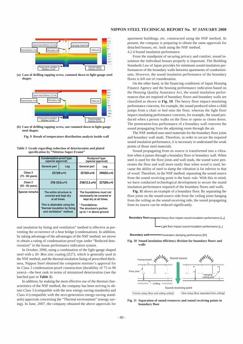
Fig. 9 shows the results of reproduction of the temperature distri-butions inside the walls when the external temperature was –20℃and the internal temperature was 23℃ (see Fig. 8). The calculatedtemperature of the hollow part is 16.7℃ and that of the tapping screwis 13.1℃. The measured temperature is 16.7℃ for the hollow partand 13.8℃ for the tapping screw. Although there is a temperaturedifference of 0.7℃ for the tapping screw, considering the differenceof 43℃ between the internal and external temperatures, it may besaid that the analysis results reflect the actual conditions fairly well.
When a drilling tapping screw is driven into the light-gauge shapedsteel (see Fig. 9(a)), the tip of the screw is heated to a temperature atwhich there is no risk of condensation. On the other hand, when thedrilling tapping screw is not driven into the light-gauge shaped steel(see Fig. 9(b)), the possibility of condensation increases significantly.Namely, the light-gauge shaped steel itself supplies the internal heatto the drilling tapping screw that penetrates the thermal insulation,thereby restraining the creation of a cold bridge inside the wall andcondensation.
Through the above analysis, we clarified the mechanism wherebythe light-gauge shaped steel itself restrains the creation of a coldbridge and condensation inside the walls, and confirmed that the “ther-
BedroomBathroom
Washroom Closet
Spare room
Japanese-style room
Children's room
Utility roomStairwell
Japanese-style room
Attic
Light-gauge steel shapes assembled in the stairwell
Fig. 7 Summery of Engaru-specification (1st floor plan [upper left],2nd floor plan [upper right], section [lower left], introspectivephoto under construction [lower right])
Photo 5 Steel framed house constructed in Engaru City, Hokkaido
Tem
pera
ture
(°C
)
Condensation point
Condensation point when relative humidity is 80%
Internal temperature Hollow part Light-gauge shaped steel
Drilling tapping screw External temperature
Fig. 8 Thermal environment and dew condensation decision insidewall of winter season
NIPPON STEEL TECHNICAL REPORT No. 97 JANUARY 2008
- 89 -
mal insulation by lining and ventilation” method is effective at pre-venting the occurrence of a heat bridge (condensation). In addition,by taking advantage of the advantages of the NSF method, we stroveto obtain a rating of condensation-proof type under “Reduced dete-rioration” in the house performance indication system.
In October, 2006, using a combination of the light-gauge shapedsteel with a 20-μm zinc coating (Z27), which is generally used inthe NSF method, and the thermal insulation lining of prescribed thick-ness, Nippon Steel obtained the competent minister’s approval forits Class 3 condensation-proof construction (durability of 75 to 90years)—the best rank in terms of minimized deterioration (see thehatched part in Table 3).
In addition, by making the most effective use of the thermal char-acteristics of the NSF method, the company has been striving to ob-tain Class 3 (compatible with the new energy-saving standards) andClass 4 (compatible with the next-generation energy-saving stand-ards) approvals concerning the “Thermal environment” (energy sav-ing). In June, 2007, the company obtained the above approvals for
apartment buildings, etc. constructed using the NSF method. Atpresent, the company is preparing to obtain the same approvals fordetached houses, etc. built using the NSF method.4.2.4 Sound insulation performance
From the standpoint of securing privacy and comfort, sound in-sulation the individual houses properly is important. The BuildingStandards Law of Japan provides for minimum sound insulation per-formances of the boundary walls between apartments of condomini-ums. However, the sound insulation performance of the boundaryfloors is left out of consideration.
On the other hand, in the financing conditions of Japan HousingFinance Agency and the housing performance indication based onthe Housing Quality Assurance Act, the sound insulation perfor-mances that are required of boundary floors and boundary walls areclassified as shown in Fig. 10. The heavy floor impact-insulatingperformance concerns, for example, the sound produced when a childjumps from a chair or bed onto the floor, whereas the light floorimpact-insulating performance concerns, for example, the sound pro-duced when a person walks on the floor or opens or closes doors.The penetration-loss performance of a boundary wall concerns thesound propagating from the adjoining room through the air.
The NSF method uses steel materials for the boundary floor joistsand boundary wall studs. Therefore, in order to secure the requiredsound insulation performance, it is necessary to understand the weakpoints of those steel materials.
Sound propagating from its source is transformed into a vibra-tion when it passes through a boundary floor or boundary wall. Whensteel is used for the floor joists and wall studs, the sound wave pen-etrates the floor and wall more easily than when wood is used, be-cause the ability of steel to damp the vibration is far inferior to thatof wood. Therefore, in the NSF method, separating the sound sourcefrom the sound receiving point is the basic rule. With this in mind,we have conducted technological development to secure the soundinsulation performance required of the boundary floors and walls.
Fig. 11 shows an example of a boundary floor. By separating thefloor joists on the sound-source side from the ceiling joists hangingfrom the ceiling on the sound-receiving side, the sound propagatingfrom its source can be reduced significantly.
Gypsum board (thickness: 12.5 mm) Light-gauge shaped steel
Plywood (thickness: 9 mm) Drilling tapping screw Hollow part
Furring strip for ventilation (thickness: 18 mm)
Thermal-insulation (thickness: 60 mm)
Gypsum board (thickness: 12.5 mm)
Plywood (thickness: 9 mm) Drilling tapping screw Hollow part
Furring strip for ventilation (thickness: 18 mm) Thermal-insulation
(thickness: 60 mm)
(a) Case of drilling tapping screw, rammed down to light-gauge steelshapes
(b) Case of drilling tapping screw, not rammed down to light-gaugesteel shapes
Fig. 9 Result of temperature distribution analysis inside wall
Class 3 (75 - 90 years)
Class 2 (50 - 60 years)
Special remarks
Condensation-proof type (special approval)
The entire structure is covered and kept dry
at all times.
General part Leg General part Leg
Rustproof type (special approval)
This is attainable using the “thermal insulation by lining
and ventilation” method.
The foundations must not necessarily be covered or
kept dry at all times.
* Foundations: The structure's portion up to 1 m above ground.
Table 3 Grade regarding reduction of deterioration and platedspecification by “Nittetsu-Super-Frame”
Boundary floor Heavy floor impact sound insulation performance [LH]
Light floor impact sound insulation performance [LL]
Boundary wall Penetration damping performance [Rr]
Facing board Sound source
Floor joist
Ceiling
Hanging ceiling joist
Former setup (floor and ceiling united)
Sound-receiving point
New setup (floor separated from ceiling)
Fig. 11 Separation of sound resources and sound receiving points inboundary floor
Fig. 10 Sound insulation efficiency division for boundary floors andwalls

NIPPON STEEL TECHNICAL REPORT No. 97 JANUARY 2008
- 90 -
Taking a foreign students’ dormitory constructed on KitakyushuScience and Research Park as an example, we shall describe belowthe sound insulation performance of the NSF method. From the stand-point of securing a high level of living comfort, sound insulationperformance of Grade 2 or higher specified by the housing perfor-mance indication system was required of the boundary floors andwalls of the dormitory. Measurement and evaluation of the actualsound insulation performance was entrusted to Kuroki Laboratoryof the International Environmental Engineering Department ofKitakyushu Municipal University.(1)Heavy floor impact sound-insulating performance of boundary
floorsFig. 12 shows the impact application points in Room No. 203
and the sound measurement points in Room No. 103, directly be-neath Room No. 203, in the measurement of heavy floor impactsound-insulating performance of the boundary floor. The measure-ment results are shown in Fig. 13. The sound pressure level of cen-tral frequency 63 Hz is highest. The boundary floor thus demon-strates “Grade 2” sound insulation performance at L-65.
Concerning the obtaining of performance grades based on thehousing performance indication system, the Building Center of Ja-pan has just completed evaluation of the boundary floor performanceas Grade 2, which corresponds to an RC floor slab thickness of 11cm. In the future, the company intends to make further improve-ments to obtain Grade 3 approval, corresponding to an RC floor slabthickness of 15 cm.(2)Light floor impact sound-insulating performance of boundary
floorsFig. 14 shows the results of measurement of light floor impact
sound-insulating performance at the impact points and measuringpoints shown in Fig. 12. The boundary floor has Grade 2 light floorimpact sound-insulating performance at L-60.(3)Airborne Sound insulating performance of boundary walls
Fig. 15 shows the measurement points of the airborne sound in-sulating performance of the boundary wall, and Fig. 16 shows themeasurement results. In the low-frequency band (center frequency:125 Hz), studs were arranged in a checkered pattern to isolate the
Center frequency (Hz)
Sou
nd p
ress
ure
leve
l (dB
)
Impact points (Room No. 203) and sound-receiving
points (Room No. 103)
Fig. 12 Impacting points in Room No.203 and sound receiving pointsin Room No.103
Fig. 13 Heavy impact sound insulation performance of upper floor ofRoom No.103
Center frequency (Hz)
Sou
nd p
ress
ure
leve
l (dB
)
Fig. 14 Light impact sound insulation performance of upper floor ofRoom No.103
Boundary wall
Sound receiving points (Room No. 103)
Fig. 16 Airborne sound insulation performance of boundary walls ofRoom No.103
Fig. 15 Sound source points (No.102, No.104) and sound receivingpoints in Room No.103
Airborne sound insulation performance of boundary walls (sound source: Room No. 103 --> sound receiving rooms: Room Nos. 102 and 104)
Boundary wall between Room Nos. 103 and 104
Boundary wall between Room Nos. 102 and 103
Center frequency (Hz)
Sou
nd p
ress
ure
leve
l (dB
)

NIPPON STEEL TECHNICAL REPORT No. 97 JANUARY 2008
- 91 -
power source from the power-receiving point. At the same time, inthe high-frequency band (center frequency: 2,000 Hz), two gypsumboards were varied in thickness to suppress the coincidence. As aresult, it was confirmed that the boundary wall had Grade 3 airbornesound insulating performance (D-45).
On the basis of the above results, the company strove to obtainthe performance grade based on the housing performance indicationsystem. As a result, approval for Grade 3 was obtained in December,2005. Grade 3 corresponds to the performance of a concrete bound-ary wall having a thickness of 18 cm.
5. Advantages of the Nittetsu Super Frame (NSF)Method from the Standpoint of Countering Glob-al WarmingIn this section, we shall discuss the advantages of steel-framed
houses constructed using the NSF method in terms of the reductionin environmental impact throughout their life cycle, from construc-tion to utilization to scrapping.5.1 Reduction of environmental impact during construction
In the case of a three-storied apartment building of reinforcedconcrete (RC) construction, the body weight per total floor area isabout 1 ton/m2. In striking contrast, the body weight of a three-sto-ried apartment building constructed using the NSF method is about100 kg/m2, including the facing boards, one-tenth that of RC con-struction. Because of this, even in cases where foundation piles arerequired for RC construction, the NSF method seldom requires them.Thus, the NSF method helps reduce the environmental impact dur-ing construction.
Photo 6 shows a scene from the on-site installation of the struc-tural frames, thermal insulation and furring strips for ventilation, allprefabricated into panels at the factory. All that remains to be done isto provide the exterior and interior wall linings. Thus, it may be saidthat the NSF method is one that permits significant shortening of theconstruction period and minimizing the creation of waste at the con-struction site because the majority of the structural members are pre-fabricated at the factory.
To sum up, from the standpoint of reducing the environmentalimpact, the advantages of the NSF method at the construction stageare “lightweight construction materials,” “fabrication of main struc-tural members at factory” and “short construction period.”5.2 Reduction of environmental impact during utilization
The NSF method achieves high levels of thermal insulation andair-tightness for a steel-framed house by completely covering theentire living space of the house. As shown in the photo at the centerof Fig. 17, steel members with high thermal conductivity are arranged
inside the thermal insulation on the room side. Thanks to the steelmember, the thermal energy of the heater used in cold weather spreadsthroughout the room interior. As is evident from the photo at theright of Fig. 17, the occurrence of temperature variance can be mini-mized. In districts northeast of Tokyo where the heating load is greaterthan the cooling load, by adjusting the thickness of thermal insula-tion according to external conditions and positively letting solar heatand other natural energies into the room, it is possible to create anice and warm room environment which requires less energy forheating.
On the other hand, in districts west of Tokyo where the annualcooling load is greater than the annual heating load, even when thethermal insulation performance is raised in hot weather, the heat thathas entered the room via the roof and walls and through the windowsand other openings can hardly be let out of the room. In those dis-tricts, therefore, reinforcing the thermal insulation performance alonewill not significantly reduce the cooling load.
In order to promote the NSF method in the warm districts west ofTokyo as well, Nippon Steel has conducted technological develop-ments to add sun-shading technique to the “thermal insulation byexterior lining and ventilation” method. The phrase “sun-shadingtechnique” as used here refers to technology to restrain the entry ofheat (solar heat) into the room via the roof, walls and other non openparts. The basic principles of sun-shading technique are shown inFig. 18.
Specifically, the above technology aims to reduce the coolingload by increasing the solar reflection rate of the surface of the exte-rior materials, making the entry of solar heat into the room difficultby decreasing the surface radiation rate of at least one side of theventilation part, and enhancing the ventilation. At present, the com-pany is conducting a verification study at building A of the conven-tional thermal insulation/ventilation specifications (compatible withthe next-generation energy-saving standards) and building B added
Photo 6 Exterior wall panels, increasing ratio of factory production
Thermal conductor
Heat source
Fig. 17 Process of high performance living space of resource produc-tivity for space heating and cooling
Reflection of sunlight
Ventilation inside wall
Radiation
Fig. 18 Three principles of sunshading in external walls

NIPPON STEEL TECHNICAL REPORT No. 97 JANUARY 2008
- 92 -
with a sun-shading technique function, both constructed on the prem-ises of Kagoshima University (see Photo 7).
Fig. 19 shows the daily variations in heat transfer for buildings Aand B during the period from September, 2005 to February, 2006.The positive (+) side of the vertical axis represents the quantity ofheat flowing into the room from the outside, and the negative (–)side represents the quantity of heat flowing out from the room to theoutside. Until the room heating was turned on (December 2, 2005),building B with the sun-shading technique function added dramati-cally reduced the quantity of heat flowing into the room from theoutside, as compared to building A. In building B, the quantity ofheat flowing out of the room also decreased. It can be seen that evenafter the room heating was turned on, the amount of heat lost fromthe room to the outside fell a little.4,5)
To sum up, from the standpoint of reducing the environmentalimpact, the advantage of the NSF method in terms of utilization ofthe house is “high energy efficiency made possible by thermal insu-lation and sun-shading technique.”5.3 Reduction of environmental impact during dismantling/
scrappingAs mentioned in 2.2, the NSF method does not use welding at
all. It is a dry-type construction method that uses drilling tappingscrews to assemble the main structural members. Therefore, steel-framed houses constructed using this method can easily be disas-sembled by removing those screws.
On the other hand, when it comes to demolishing an RC buildingconstructed by the wet-type method, a large amount of energy isrequired to demolish the concrete. Besides, it is necessary to erecttemporary walls to insulate against the resultant cacophony andsprinkle large amounts of water to prevent dispersal of particulates.
As already mentioned in 5.1, since a steel-framed house builtusing the NSF method is much lighter than an RC building, the totalcost of demolition can be cut dramatically. As shown in Fig. 20, thewaste from the average steel-framed house can be broken down intoconcrete used for the foundation (78.5%), wood chips and gypsumboard (11.5%), steel from light-gauge shaped steel (7.1%), and rein-forcement (2.5%). All the waste materials, except for composite ones,can be recycled in the form of “sub-base course materials” and “iron.”Thus, the NSF method can be among the front-runners in a resource-recycling-based society.
To summarize, from the standpoint of reducing the environmen-tal impact, the advantages of the NSF method during demolition/scrapping are “easy demolition and high rate of resource recycling.”
6. Promoting Application of the NSF Method to theLow-Rise Building MarketThe application of the NSF method in the field of low-rise build-
ings began in Hokkaido where the thermal-insulating performanceof NSF steel-framed houses was very highly rated. For example, theNSF method was applied to construct group homes in Kitami Cityand Asahikawa City (Photos 8 and 9). More recently, a certain hous-ing sales company in Sapporo City adopted urban-type, three-sto-ried apartment buildings (fire-resistant buildings), like the one shownin Photo 10, as standard steel-framed houses. Since then, the num-ber of steel-framed houses in Hokkaido has been expanding rapidly.
In the Kanto area, steel-framed houses applying the NSF method
Building B (with sun-shading technique added)
Building A (conventional specifications)
Room heating turned on
Hea
t tra
nsfe
r ra
te [k
Wh/
day]
Building A Building B
Inflow
Outflow
Photo 7 Two-story detached houses for on-site practical study atKagoshima University
Fig. 19 Daily variation of thermal transmission quantity in whole walland roof of two-story detached houses
Gypsum board Composite waste
Wood chipsSteel
Reinforcement, etc.
Body
Foundation
Waste concrete
Fig. 20 Rates of recycling and reuse of resources at time of demolitionof steel framed house
Photo 8 Group home in Kitami City, Hokkaido

NIPPON STEEL TECHNICAL REPORT No. 97 JANUARY 2008
- 93 -
are steadily increasing in number, especially in the field of urban-type, three-storied apartment buildings (fire-resistant buildings) builton confined grounds. For example, they can be found in Minami-Ikebukuro (2004) (see Photo 11), Funabashi City and Chiba City(2005), and Chofu City (2006) (see Photo 12).
The application of the NSF method to dormitories and companyhouses, too, has begun increasing steadily, such as the foreign stu-dents’ dormitory in Kitakyushu City (2004) (see Photo 13), theTakayokosuka company house in the grounds of the Nippon SteelNagoya Works (2006) (see Photo 14) and the employees’ dormitoryin the grounds of the Nippon Steel Kamaishi Works (2007). In the
Photo 9 Group home in Asahikawa City, Hokkaido
Photo 10 Three-story apartment, city type, in Sapporo City, Hokkaido(1-hour fire-resistant building)
Photo 11 Three-story apartment, city type and narrow small area, inMinami-Ikebukuro, Tokyo (1-hour fire-resistant building)
Photo 12 Three-story apartment, city type and narrow small area, inChofu City, Tokyo (1-hour fire-resistant building)
Photo 13 Three-story dormitory for foreign students in KitakyushuCity (60-minute quasi- fire-resistant building)
Photo 14 Three-story apartment for employees of Nagoya Works inTakayokosuka, Aichi (1-hour fire-resistant building)
case of the foreign students’ dormitory in Kitakyushu City, in par-ticular, it was a precondition that the land should be cleared of thebuilding and returned to the city 20 years later. Therefore, it wasvery desirable that the building be such that it could be completelydepreciated within 20 years. In terms of the Tax Law, the period of
Photo 15 Convenience store in Saitama City

NIPPON STEEL TECHNICAL REPORT No. 97 JANUARY 2008
- 94 -
depreciation of a steel-framed house is 19 years since it uses thin-gauge steel sheet for its frames. The exceptionally short depreciationperiod, as compared with 34 years for steel-framed construction and47 years for RC construction, was one of the major reasons why theNSF method was adopted for the foreign students’ dormitory men-tioned above.
The NSF method is also steadily penetrating the shop market. Inmany cases, shops are based on a fixed-period leasehold. In additionto the exceptionally short depreciation period mentioned above, thefact that the shop owner can start business quickly (thanks to theshort construction period) and can make the most effective use of thefloor space (because of the total absence of pillars or columns) ishighly rated. Photo 15 shows an example of a steel-framed conven-ience store.
7. ConclusionConcerning the Nittetsu Super Frame (NSF) method, which is an
improved version of the steel frame construction method co-devel-oped by Japan’s major steelmakers and which targets the low-risebuilding market, we have so far described the development conceptand our activities to secure the required performance requirementsand discussed the advantages of the NSF method from the stand-point of reducing the environmental impact. So far, our activitieshave been focused on “expanding the application of light-gauge steelconstruction materials in the low-rise building market and determin-ing their limits.”
In cooperation with METO KAKEFU (location: Kani City, GifuPrefecture, president: Takeshi Kakefu), we have also built and accu-mulated CAD/CAM online production techniques to develop thepotential of light-gauge steel construction materials. In this respect,the most fundamental element is “pre-notched holes” which are drilledonline in the cold-forming process of light-gauge shaped steel.
By effectively utilizing the pre-notched holes, it is possible, forexample, to completely eliminate the work of measuring steel mate-rials. This can be done by providing assembly holes at both ends ofthe individual members according to the design information and byinserting pins into the appropriate holes for assembly. In addition, asshown in Photo 16, by drilling holes about 3 mm in diameter—smallerthan the diameter of the drilling tapping screw—in the studs at bothends of each panes and driving screws into all such holes, it is pos-sible to prevent some screws from being left unused and to controlthe work quality. Furthermore, by providing through-holes for pip-ing in the floor joists during fabrication of light-gauge shaped steel,
it is possible to render field drilling work, which can hardly be car-ried out efficiently, completely obsolete. This helps to improve pro-ductivity at the panel fabrication factory and at the construction site,as well as improve the construction quality.
In the future, we intend to develop higher levels of industrializedhouses, for example, byincreasing the proportions of factory pro-duction of structural members, including the drilling of piping holesat the factory as shown in Photo 17. Since the verification study onthe sun-shading technique described in 5.2 is scheduled for comple-tion during fiscal 2007, from the standpoint of reducing the environ-mental impact, the NSF method can become an effective methodeven in countries in East Asia which are warmer than Japan. Withthe aim of promoting the NSF method in East Asia as a standardmethod of construction of houses there, we are determined to con-tinue steadily developing the NSF method.
References1) Sakumoto, Y.: Steel-Framed Houses and Steel Materials. ISIJ Technical
Lecture Commemorating Nishiyama, 1998-32) Murahashi, Y.: Construction Example and Housing Performance on Light-
Gauge Steel Framed Apartment House in Japan. Proceeding of the 8thKorea-China-Japan Symposium on Structural Steel Construction. 2005-10, p.131-138
3) Murahashi, Y., Suzuki, K., Tonooka, Y., Sakumoto, Y.: Evaluation of theThermal Environment and Energy Consumption of the Indoor and InsideWall of a Light-Gauge Steel Framed Residential House with ExternalThermal Insulation Structure. Collection of Environmental Papers & Re-ports of Architectural Institute of Japan. (579), 1-8 (2004-5)
4) Murahashi, Y., Akasaka, H., Takeda, K., Kawakami, H.: QuantitativeEvaluation of Techniques for Sunshading and Thermal Insulation of Ven-tilated Exterior Walls and Roofs (Part 7). Collection of Excerpts of Aca-demic Lectures at Architectural Institute of Japan. D2, 2006, p. 131-132
5) Murahashi, Y., Akasaka, H., Takeda, K., Kawakami, H., Kurayama, C.:Evaluation of the Proposed Calculation Method for the Sunshading andInsulating Effect through Comparison; Study on Calculation Method forthe Evaluation of Sunshading and Insulating Effect of the Walls and Roofswith Vented Air-Layer (Part 2). Collection of Environmental Papers &Reports of Architectural Institute of Japan. No. 620, 89-96 (2007-10)
6) Hirakawa, T., Murahashi, Y., Sakumoto, Y.: Japan Association for FireScience and Engineering. 54(6), 18-24 (2004.12)
7) National Institute for Land and Infrastructure Management of Ministryof Land, Infrastructure, Transport and Tourism, Building Reseach Insti-tute, Japan Iron and Steel Federation: Design Manual for Light-GaugeSteel-Framed Structures, 1st Edition, Gihoudo Publishing Co. 2002-6
Pre-notched holes for piping
Photo 17 Pre-notched holes for piping penetration to structural faceboard
Pre-notched holes for hanging wall panel
during erection
Pre-notched holes
Holes for wiring
Photo 16 Pre-notched holes, raising productivity and competitiveness


![[OPS] One Piece 691 Fr (fairynopiece.shonenblog.com)](https://static.fdocuments.us/doc/165x107/568c38ef1a28ab0235a08e93/ops-one-piece-691-fr-fairynopieceshonenblogcom.jpg)


