UD UNIVERSAL Drive - TecDriver® - Conserto em ... PARTE 1 V19.pdf25.04.03 Operating Instructions...
56
Operating Instructions Part 1 UD UNIVERSAL Drive
Transcript of UD UNIVERSAL Drive - TecDriver® - Conserto em ... PARTE 1 V19.pdf25.04.03 Operating Instructions...

Operating InstructionsPart 1
UDUNIVERSAL Drive


Table of Contents
25.04.03 Operating Instructions
07_GB_T1 UD 7000 — 1.5–55.0 1-1
Table of Contents (Operating Instructions [Part 1])
Page
1 General Information . . . . . . . . . . . . . . . . . . . . . . . . . . . . . . . . . . . . . . . . . . . . . . . . . . . . . . . . . . . . . . . . . . . . . . . . . . . . . . . . . . . . . . . . . .31.1 Explanation of Symbols and Notes . . . . . . . . . . . . . . . . . . . . . . . . . . . . . . . . . . . . . . . . . . . . . . . . . . . . . . . . . . . . . . . . . . . . . . . . . . .31.2 Safety and Operating Instructions for Drive Converters . . . . . . . . . . . . . . . . . . . . . . . . . . . . . . . . . . . . . . . . . . . . . . . . . . . . . . . . . . .31.3 Preface . . . . . . . . . . . . . . . . . . . . . . . . . . . . . . . . . . . . . . . . . . . . . . . . . . . . . . . . . . . . . . . . . . . . . . . . . . . . . . . . . . . . . . . . . . . . . . . .51.4 Description of Functions . . . . . . . . . . . . . . . . . . . . . . . . . . . . . . . . . . . . . . . . . . . . . . . . . . . . . . . . . . . . . . . . . . . . . . . . . . . . . . . . . . .61.5 Power Section . . . . . . . . . . . . . . . . . . . . . . . . . . . . . . . . . . . . . . . . . . . . . . . . . . . . . . . . . . . . . . . . . . . . . . . . . . . . . . . . . . . . . . . . . . .71.6 Inverter Control . . . . . . . . . . . . . . . . . . . . . . . . . . . . . . . . . . . . . . . . . . . . . . . . . . . . . . . . . . . . . . . . . . . . . . . . . . . . . . . . . . . . . . . . . .7
2 Installation . . . . . . . . . . . . . . . . . . . . . . . . . . . . . . . . . . . . . . . . . . . . . . . . . . . . . . . . . . . . . . . . . . . . . . . . . . . . . . . . . . . . . . . . . . . . . . . . . .92.1 Inspection of Unit after Delivery. . . . . . . . . . . . . . . . . . . . . . . . . . . . . . . . . . . . . . . . . . . . . . . . . . . . . . . . . . . . . . . . . . . . . . . . . . . . . .92.2 General Installation Instructions . . . . . . . . . . . . . . . . . . . . . . . . . . . . . . . . . . . . . . . . . . . . . . . . . . . . . . . . . . . . . . . . . . . . . . . . . . . . .92.3 EMC (Electromagnetic Compatibility) . . . . . . . . . . . . . . . . . . . . . . . . . . . . . . . . . . . . . . . . . . . . . . . . . . . . . . . . . . . . . . . . . . . . . . . .10
2.3.1 Limit Classes. . . . . . . . . . . . . . . . . . . . . . . . . . . . . . . . . . . . . . . . . . . . . . . . . . . . . . . . . . . . . . . . . . . . . . . . . . . . . . . . . . . . .102.3.2 Filter Components. . . . . . . . . . . . . . . . . . . . . . . . . . . . . . . . . . . . . . . . . . . . . . . . . . . . . . . . . . . . . . . . . . . . . . . . . . . . . . . . .112.3.3 Interference Suppression Measures . . . . . . . . . . . . . . . . . . . . . . . . . . . . . . . . . . . . . . . . . . . . . . . . . . . . . . . . . . . . . . . . . . .112.3.4 EMC Ordinance (EMC Directive, 89/336 EEC). . . . . . . . . . . . . . . . . . . . . . . . . . . . . . . . . . . . . . . . . . . . . . . . . . . . . . . . . . .13
2.4 Wiring Practices. . . . . . . . . . . . . . . . . . . . . . . . . . . . . . . . . . . . . . . . . . . . . . . . . . . . . . . . . . . . . . . . . . . . . . . . . . . . . . . . . . . . . . . . .142.4.1 Applicable Codes . . . . . . . . . . . . . . . . . . . . . . . . . . . . . . . . . . . . . . . . . . . . . . . . . . . . . . . . . . . . . . . . . . . . . . . . . . . . . . . . .142.4.2 Power Wiring. . . . . . . . . . . . . . . . . . . . . . . . . . . . . . . . . . . . . . . . . . . . . . . . . . . . . . . . . . . . . . . . . . . . . . . . . . . . . . . . . . . . .142.4.3 Control Lines/Interface . . . . . . . . . . . . . . . . . . . . . . . . . . . . . . . . . . . . . . . . . . . . . . . . . . . . . . . . . . . . . . . . . . . . . . . . . . . . .14
2.5 Line Power Connection . . . . . . . . . . . . . . . . . . . . . . . . . . . . . . . . . . . . . . . . . . . . . . . . . . . . . . . . . . . . . . . . . . . . . . . . . . . . . . . . . . .152.5.1 Line Conditions . . . . . . . . . . . . . . . . . . . . . . . . . . . . . . . . . . . . . . . . . . . . . . . . . . . . . . . . . . . . . . . . . . . . . . . . . . . . . . . . . . .162.5.2 Line Fusing . . . . . . . . . . . . . . . . . . . . . . . . . . . . . . . . . . . . . . . . . . . . . . . . . . . . . . . . . . . . . . . . . . . . . . . . . . . . . . . . . . . . . .172.5.3 Using Line Filters . . . . . . . . . . . . . . . . . . . . . . . . . . . . . . . . . . . . . . . . . . . . . . . . . . . . . . . . . . . . . . . . . . . . . . . . . . . . . . . . .182.5.4 Start-Up on the Line . . . . . . . . . . . . . . . . . . . . . . . . . . . . . . . . . . . . . . . . . . . . . . . . . . . . . . . . . . . . . . . . . . . . . . . . . . . . . . .182.5.5 Reducing Current Surges and Voltage Transients . . . . . . . . . . . . . . . . . . . . . . . . . . . . . . . . . . . . . . . . . . . . . . . . . . . . . . . .19
2.6 Motor Connection . . . . . . . . . . . . . . . . . . . . . . . . . . . . . . . . . . . . . . . . . . . . . . . . . . . . . . . . . . . . . . . . . . . . . . . . . . . . . . . . . . . . . . .192.7 Brake Resistor . . . . . . . . . . . . . . . . . . . . . . . . . . . . . . . . . . . . . . . . . . . . . . . . . . . . . . . . . . . . . . . . . . . . . . . . . . . . . . . . . . . . . . . . . .202.8 Functions and Use of the Terminals . . . . . . . . . . . . . . . . . . . . . . . . . . . . . . . . . . . . . . . . . . . . . . . . . . . . . . . . . . . . . . . . . . . . . . . . .20
2.8.1 Power Terminals . . . . . . . . . . . . . . . . . . . . . . . . . . . . . . . . . . . . . . . . . . . . . . . . . . . . . . . . . . . . . . . . . . . . . . . . . . . . . . . . . .222.8.2 Control Terminals . . . . . . . . . . . . . . . . . . . . . . . . . . . . . . . . . . . . . . . . . . . . . . . . . . . . . . . . . . . . . . . . . . . . . . . . . . . . . . . . .23
2.9 Typical Control Terminal Assignments . . . . . . . . . . . . . . . . . . . . . . . . . . . . . . . . . . . . . . . . . . . . . . . . . . . . . . . . . . . . . . . . . . . . . . .273 Technical Data . . . . . . . . . . . . . . . . . . . . . . . . . . . . . . . . . . . . . . . . . . . . . . . . . . . . . . . . . . . . . . . . . . . . . . . . . . . . . . . . . . . . . . . . . . . . . .28
3.1 Output Data . . . . . . . . . . . . . . . . . . . . . . . . . . . . . . . . . . . . . . . . . . . . . . . . . . . . . . . . . . . . . . . . . . . . . . . . . . . . . . . . . . . . . . . . . . . .283.2 Input Data . . . . . . . . . . . . . . . . . . . . . . . . . . . . . . . . . . . . . . . . . . . . . . . . . . . . . . . . . . . . . . . . . . . . . . . . . . . . . . . . . . . . . . . . . . . . .283.3 Control Data . . . . . . . . . . . . . . . . . . . . . . . . . . . . . . . . . . . . . . . . . . . . . . . . . . . . . . . . . . . . . . . . . . . . . . . . . . . . . . . . . . . . . . . . . . .293.4 Protective Function . . . . . . . . . . . . . . . . . . . . . . . . . . . . . . . . . . . . . . . . . . . . . . . . . . . . . . . . . . . . . . . . . . . . . . . . . . . . . . . . . . . . . .293.5 Brake Chopper Power Dissipation. . . . . . . . . . . . . . . . . . . . . . . . . . . . . . . . . . . . . . . . . . . . . . . . . . . . . . . . . . . . . . . . . . . . . . . . . . .303.6 Display and Operating Unit . . . . . . . . . . . . . . . . . . . . . . . . . . . . . . . . . . . . . . . . . . . . . . . . . . . . . . . . . . . . . . . . . . . . . . . . . . . . . . . .303.7 Parameter Groups . . . . . . . . . . . . . . . . . . . . . . . . . . . . . . . . . . . . . . . . . . . . . . . . . . . . . . . . . . . . . . . . . . . . . . . . . . . . . . . . . . . . . . .313.8 Mechanical Design and Ambient Conditions . . . . . . . . . . . . . . . . . . . . . . . . . . . . . . . . . . . . . . . . . . . . . . . . . . . . . . . . . . . . . . . . . . .313.9 Dimensions . . . . . . . . . . . . . . . . . . . . . . . . . . . . . . . . . . . . . . . . . . . . . . . . . . . . . . . . . . . . . . . . . . . . . . . . . . . . . . . . . . . . . . . . . . . .32
4 Drive Variants . . . . . . . . . . . . . . . . . . . . . . . . . . . . . . . . . . . . . . . . . . . . . . . . . . . . . . . . . . . . . . . . . . . . . . . . . . . . . . . . . . . . . . . . . . . . . .344.1 The Motor Drive Data and How it is Measured . . . . . . . . . . . . . . . . . . . . . . . . . . . . . . . . . . . . . . . . . . . . . . . . . . . . . . . . . . . . . . . . .344.2 The Asynchronous Motor and Speed Control . . . . . . . . . . . . . . . . . . . . . . . . . . . . . . . . . . . . . . . . . . . . . . . . . . . . . . . . . . . . . . . . . .34
4.2.1 V/f-Controlled Operation . . . . . . . . . . . . . . . . . . . . . . . . . . . . . . . . . . . . . . . . . . . . . . . . . . . . . . . . . . . . . . . . . . . . . . . . . . . .354.2.2 Field-Orientated-Controlled Mode (Vector Control) . . . . . . . . . . . . . . . . . . . . . . . . . . . . . . . . . . . . . . . . . . . . . . . . . . . . . . .384.2.3 SLV (Sensorless Vector Control) . . . . . . . . . . . . . . . . . . . . . . . . . . . . . . . . . . . . . . . . . . . . . . . . . . . . . . . . . . . . . . . . . . . . .39
4.3 The EC Drive . . . . . . . . . . . . . . . . . . . . . . . . . . . . . . . . . . . . . . . . . . . . . . . . . . . . . . . . . . . . . . . . . . . . . . . . . . . . . . . . . . . . . . . . . . .425 Annex . . . . . . . . . . . . . . . . . . . . . . . . . . . . . . . . . . . . . . . . . . . . . . . . . . . . . . . . . . . . . . . . . . . . . . . . . . . . . . . . . . . . . . . . . . . . . . . . . . . . .43
5.1 Abbreviations Used . . . . . . . . . . . . . . . . . . . . . . . . . . . . . . . . . . . . . . . . . . . . . . . . . . . . . . . . . . . . . . . . . . . . . . . . . . . . . . . . . . . . . .435.2 Parameter Structure . . . . . . . . . . . . . . . . . . . . . . . . . . . . . . . . . . . . . . . . . . . . . . . . . . . . . . . . . . . . . . . . . . . . . . . . . . . . . . . . . . . . .445.3 Parameter Overview . . . . . . . . . . . . . . . . . . . . . . . . . . . . . . . . . . . . . . . . . . . . . . . . . . . . . . . . . . . . . . . . . . . . . . . . . . . . . . . . . . . . .455.4 Error States . . . . . . . . . . . . . . . . . . . . . . . . . . . . . . . . . . . . . . . . . . . . . . . . . . . . . . . . . . . . . . . . . . . . . . . . . . . . . . . . . . . . . . . . . . . .50
5.4.1 Normal Handling of Error States . . . . . . . . . . . . . . . . . . . . . . . . . . . . . . . . . . . . . . . . . . . . . . . . . . . . . . . . . . . . . . . . . . . . . .505.4.2 Handling of Error States with the “Acknowledge Error State” Function . . . . . . . . . . . . . . . . . . . . . . . . . . . . . . . . . . . . . . . .50

Table of Contents
Operating Instructions 25.04.03
UD 7000 — 1.5–55.0 07_GB_T11-2
Table of Contents (Parameter Description [Part 2])
Page
6 Commissioning . . . . . . . . . . . . . . . . . . . . . . . . . . . . . . . . . . . . . . . . . . . . . . . . . . . . . . . . . . . . . . . . . . . . . . . . . . . . . . . . . . . . . . . . . . . . . 36.1 Prior to Switch-On . . . . . . . . . . . . . . . . . . . . . . . . . . . . . . . . . . . . . . . . . . . . . . . . . . . . . . . . . . . . . . . . . . . . . . . . . . . . . . . . . . . . . . . 36.2 What Happens on Switch-On . . . . . . . . . . . . . . . . . . . . . . . . . . . . . . . . . . . . . . . . . . . . . . . . . . . . . . . . . . . . . . . . . . . . . . . . . . . . . . . 56.3 Further Steps . . . . . . . . . . . . . . . . . . . . . . . . . . . . . . . . . . . . . . . . . . . . . . . . . . . . . . . . . . . . . . . . . . . . . . . . . . . . . . . . . . . . . . . . . . . 66.4 Assignment of the Control Terminals . . . . . . . . . . . . . . . . . . . . . . . . . . . . . . . . . . . . . . . . . . . . . . . . . . . . . . . . . . . . . . . . . . . . . . . . . 66.5 Parameter List/Help . . . . . . . . . . . . . . . . . . . . . . . . . . . . . . . . . . . . . . . . . . . . . . . . . . . . . . . . . . . . . . . . . . . . . . . . . . . . . . . . . . . . . . 76.6 Commissioning Application 0 – Inverter . . . . . . . . . . . . . . . . . . . . . . . . . . . . . . . . . . . . . . . . . . . . . . . . . . . . . . . . . . . . . . . . . . . . . . . 7
6.6.1 Preparation . . . . . . . . . . . . . . . . . . . . . . . . . . . . . . . . . . . . . . . . . . . . . . . . . . . . . . . . . . . . . . . . . . . . . . . . . . . . . . . . . . . . . . 76.6.2 Parameterisation . . . . . . . . . . . . . . . . . . . . . . . . . . . . . . . . . . . . . . . . . . . . . . . . . . . . . . . . . . . . . . . . . . . . . . . . . . . . . . . . . . 76.6.3 Precision Adjustment . . . . . . . . . . . . . . . . . . . . . . . . . . . . . . . . . . . . . . . . . . . . . . . . . . . . . . . . . . . . . . . . . . . . . . . . . . . . . . . 86.6.4 Solution to the Problem . . . . . . . . . . . . . . . . . . . . . . . . . . . . . . . . . . . . . . . . . . . . . . . . . . . . . . . . . . . . . . . . . . . . . . . . . . . . . 9
6.7 Commissioning of a Field-Orientated-Controlled Asynchronous Motor (FO) or of a Permanent-Field Synchronous Drive (EC). . . . 96.7.1 Hardware Precondition (Option Card and Wiring) . . . . . . . . . . . . . . . . . . . . . . . . . . . . . . . . . . . . . . . . . . . . . . . . . . . . . . . . . 96.7.2 Parameterisation of the Speed Controller on Systems with Feedback (FO and EC Applications) . . . . . . . . . . . . . . . . . . . 126.7.3 Controller Optimization . . . . . . . . . . . . . . . . . . . . . . . . . . . . . . . . . . . . . . . . . . . . . . . . . . . . . . . . . . . . . . . . . . . . . . . . . . . . 136.7.4 Solution to the Problem . . . . . . . . . . . . . . . . . . . . . . . . . . . . . . . . . . . . . . . . . . . . . . . . . . . . . . . . . . . . . . . . . . . . . . . . . . . . 16
6.8 Commissioning an SLV Application . . . . . . . . . . . . . . . . . . . . . . . . . . . . . . . . . . . . . . . . . . . . . . . . . . . . . . . . . . . . . . . . . . . . . . . . . 176.8.1 Introduction . . . . . . . . . . . . . . . . . . . . . . . . . . . . . . . . . . . . . . . . . . . . . . . . . . . . . . . . . . . . . . . . . . . . . . . . . . . . . . . . . . . . . 176.8.2 Commissioning Application 50 (SLV Rotational Speed Control) . . . . . . . . . . . . . . . . . . . . . . . . . . . . . . . . . . . . . . . . . . . . . 18
6.9 Note on Commissioning further to Application 51 . . . . . . . . . . . . . . . . . . . . . . . . . . . . . . . . . . . . . . . . . . . . . . . . . . . . . . . . . . . . . . 226.9.1 Signal Flow Diagrams . . . . . . . . . . . . . . . . . . . . . . . . . . . . . . . . . . . . . . . . . . . . . . . . . . . . . . . . . . . . . . . . . . . . . . . . . . . . . 22
6.10 Stepper Control . . . . . . . . . . . . . . . . . . . . . . . . . . . . . . . . . . . . . . . . . . . . . . . . . . . . . . . . . . . . . . . . . . . . . . . . . . . . . . . . . . . . . . . . 257 Keys and Displays/Indicators . . . . . . . . . . . . . . . . . . . . . . . . . . . . . . . . . . . . . . . . . . . . . . . . . . . . . . . . . . . . . . . . . . . . . . . . . . . . . . . . . 26
7.1 Display and Operating Unit (ABE) . . . . . . . . . . . . . . . . . . . . . . . . . . . . . . . . . . . . . . . . . . . . . . . . . . . . . . . . . . . . . . . . . . . . . . . . . . 267.2 Display in the Operating Mode . . . . . . . . . . . . . . . . . . . . . . . . . . . . . . . . . . . . . . . . . . . . . . . . . . . . . . . . . . . . . . . . . . . . . . . . . . . . . 26
7.2.1 Standard Display 1 . . . . . . . . . . . . . . . . . . . . . . . . . . . . . . . . . . . . . . . . . . . . . . . . . . . . . . . . . . . . . . . . . . . . . . . . . . . . . . . 267.2.2 Standard Display 2 . . . . . . . . . . . . . . . . . . . . . . . . . . . . . . . . . . . . . . . . . . . . . . . . . . . . . . . . . . . . . . . . . . . . . . . . . . . . . . . 277.2.3 Display in the Program Mode . . . . . . . . . . . . . . . . . . . . . . . . . . . . . . . . . . . . . . . . . . . . . . . . . . . . . . . . . . . . . . . . . . . . . . . 287.2.4 Operating Examples . . . . . . . . . . . . . . . . . . . . . . . . . . . . . . . . . . . . . . . . . . . . . . . . . . . . . . . . . . . . . . . . . . . . . . . . . . . . . . 29
7.3 On-Line Help . . . . . . . . . . . . . . . . . . . . . . . . . . . . . . . . . . . . . . . . . . . . . . . . . . . . . . . . . . . . . . . . . . . . . . . . . . . . . . . . . . . . . . . . . . 337.4 Key Functions. . . . . . . . . . . . . . . . . . . . . . . . . . . . . . . . . . . . . . . . . . . . . . . . . . . . . . . . . . . . . . . . . . . . . . . . . . . . . . . . . . . . . . . . . . 33
7.4.1 Control Keys . . . . . . . . . . . . . . . . . . . . . . . . . . . . . . . . . . . . . . . . . . . . . . . . . . . . . . . . . . . . . . . . . . . . . . . . . . . . . . . . . . . . 337.4.2 Control and Parameter Keys – Single Operation. . . . . . . . . . . . . . . . . . . . . . . . . . . . . . . . . . . . . . . . . . . . . . . . . . . . . . . . . 347.4.3 Control and Parameter Keys – Combinations with SHIFT. . . . . . . . . . . . . . . . . . . . . . . . . . . . . . . . . . . . . . . . . . . . . . . . . . 367.4.4 LED Status Display . . . . . . . . . . . . . . . . . . . . . . . . . . . . . . . . . . . . . . . . . . . . . . . . . . . . . . . . . . . . . . . . . . . . . . . . . . . . . . . 38
8 Parameter Description. . . . . . . . . . . . . . . . . . . . . . . . . . . . . . . . . . . . . . . . . . . . . . . . . . . . . . . . . . . . . . . . . . . . . . . . . . . . . . . . . . . . . . . 398.1 Group 1 – Motor Data. . . . . . . . . . . . . . . . . . . . . . . . . . . . . . . . . . . . . . . . . . . . . . . . . . . . . . . . . . . . . . . . . . . . . . . . . . . . . . . . . . . . 398.2 Group 2 – Basic Data . . . . . . . . . . . . . . . . . . . . . . . . . . . . . . . . . . . . . . . . . . . . . . . . . . . . . . . . . . . . . . . . . . . . . . . . . . . . . . . . . . . . 428.3 Group 3 – Setpoint Selection . . . . . . . . . . . . . . . . . . . . . . . . . . . . . . . . . . . . . . . . . . . . . . . . . . . . . . . . . . . . . . . . . . . . . . . . . . . . . . 578.4 Group 4 – Frequencies. . . . . . . . . . . . . . . . . . . . . . . . . . . . . . . . . . . . . . . . . . . . . . . . . . . . . . . . . . . . . . . . . . . . . . . . . . . . . . . . . . . 678.5 Group 5 – Torque . . . . . . . . . . . . . . . . . . . . . . . . . . . . . . . . . . . . . . . . . . . . . . . . . . . . . . . . . . . . . . . . . . . . . . . . . . . . . . . . . . . . . . . 698.6 Group 6 – V/Hz Characteristic . . . . . . . . . . . . . . . . . . . . . . . . . . . . . . . . . . . . . . . . . . . . . . . . . . . . . . . . . . . . . . . . . . . . . . . . . . . . . 728.7 Group 7 – Inverter Functions . . . . . . . . . . . . . . . . . . . . . . . . . . . . . . . . . . . . . . . . . . . . . . . . . . . . . . . . . . . . . . . . . . . . . . . . . . . . . . 778.8 Group 8 – Protective Functions . . . . . . . . . . . . . . . . . . . . . . . . . . . . . . . . . . . . . . . . . . . . . . . . . . . . . . . . . . . . . . . . . . . . . . . . . . . . 838.9 Group 9 – Binary Inputs/Outputs . . . . . . . . . . . . . . . . . . . . . . . . . . . . . . . . . . . . . . . . . . . . . . . . . . . . . . . . . . . . . . . . . . . . . . . . . . . 898.10 Group A – Analog Outputs/SIO . . . . . . . . . . . . . . . . . . . . . . . . . . . . . . . . . . . . . . . . . . . . . . . . . . . . . . . . . . . . . . . . . . . . . . . . . . . 1018.11 Group B – Speed Controller . . . . . . . . . . . . . . . . . . . . . . . . . . . . . . . . . . . . . . . . . . . . . . . . . . . . . . . . . . . . . . . . . . . . . . . . . . . . . . 1058.12 Group C – Stepper Control. . . . . . . . . . . . . . . . . . . . . . . . . . . . . . . . . . . . . . . . . . . . . . . . . . . . . . . . . . . . . . . . . . . . . . . . . . . . . . . 1098.13 Group D – Options . . . . . . . . . . . . . . . . . . . . . . . . . . . . . . . . . . . . . . . . . . . . . . . . . . . . . . . . . . . . . . . . . . . . . . . . . . . . . . . . . . . . . 1108.14 Group E – Service Data II . . . . . . . . . . . . . . . . . . . . . . . . . . . . . . . . . . . . . . . . . . . . . . . . . . . . . . . . . . . . . . . . . . . . . . . . . . . . . . . 1118.15 Group F – Service Data III . . . . . . . . . . . . . . . . . . . . . . . . . . . . . . . . . . . . . . . . . . . . . . . . . . . . . . . . . . . . . . . . . . . . . . . . . . . . . . . 1158.16 Group 0 – Service Data I . . . . . . . . . . . . . . . . . . . . . . . . . . . . . . . . . . . . . . . . . . . . . . . . . . . . . . . . . . . . . . . . . . . . . . . . . . . . . . . . 1208.17 Error States . . . . . . . . . . . . . . . . . . . . . . . . . . . . . . . . . . . . . . . . . . . . . . . . . . . . . . . . . . . . . . . . . . . . . . . . . . . . . . . . . . . . . . . . . . 121
8.17.1 Normal Handling of Error States . . . . . . . . . . . . . . . . . . . . . . . . . . . . . . . . . . . . . . . . . . . . . . . . . . . . . . . . . . . . . . . . . . . . 1218.17.2 Handling of Error States with the “Acknowledge Error State” Function . . . . . . . . . . . . . . . . . . . . . . . . . . . . . . . . . . . . . . . 121
9 Annex . . . . . . . . . . . . . . . . . . . . . . . . . . . . . . . . . . . . . . . . . . . . . . . . . . . . . . . . . . . . . . . . . . . . . . . . . . . . . . . . . . . . . . . . . . . . . . . . . . . 1239.1 Abbreviations Used . . . . . . . . . . . . . . . . . . . . . . . . . . . . . . . . . . . . . . . . . . . . . . . . . . . . . . . . . . . . . . . . . . . . . . . . . . . . . . . . . . . . 1239.2 Hexadecimal to Binary Conversion . . . . . . . . . . . . . . . . . . . . . . . . . . . . . . . . . . . . . . . . . . . . . . . . . . . . . . . . . . . . . . . . . . . . . . . . 1239.3 Parameter Structure . . . . . . . . . . . . . . . . . . . . . . . . . . . . . . . . . . . . . . . . . . . . . . . . . . . . . . . . . . . . . . . . . . . . . . . . . . . . . . . . . . . . 1249.4 Parameter Overview. . . . . . . . . . . . . . . . . . . . . . . . . . . . . . . . . . . . . . . . . . . . . . . . . . . . . . . . . . . . . . . . . . . . . . . . . . . . . . . . . . . . 125

25.04.03 Operating Instructions
07_GB_T1 UD 7000 — 1.5–55.0 1-3
General Information
1 General Information
1.1 Explanation of Symbols and Notes
Work Safety Symbol
You will find this symbol next to all work safety notes in this operating manual if there is arisk of injury or death for persons involved. Pay attention to these notes and observe par-ticular caution in such cases. Also pass on all work safety instructions to other users.
Voltage Warning
This symbol is shown wherever particular caution is necessary owing to occurring or ap-plied voltages (e.g. DC voltages up to 650 V) and where special precautionary measureshave to be taken. The drive converter must always be isolated from the line when workingon it.
Caution Note
This note is shown in all parts of this operating manual to which particular attention must bepaid to ensure that the guidelines, specifications, notes and the correct sequence of workwill be obeyed and to prevent damage or destruction of the drive converter and/or systems.
1.2 Safety and Operating Instructions for Drive Converters
1. General
In operation, drive converters, depending on their degree of protection, may have live,unisolated, and possibly also moving or rotating parts, as well as hot surfaces.
In case of inadmissible removal of the required covers, of improper use, wrong installationor maloperation, there is the danger of serious personal injury and damage to property.
For further information, see documentation.
All operations serving transport, installation and commissioning as well as maintenance areto be carried out by skilled technical personnel (Observe IEC 364 or CENELEC HD 384or DIN VDE 0100 and IEC 664 or DIN/VDE 0110 and national accident prevention rules!).
For the purposes of these basic safety instructions, “skilled technical personnel” means per-sons who are familiar with the installation, mounting, commissioning and operation of theproduct and have the qualifications needed for the performance of their functions.
We draw attention to the fact that no liability can be assumed for damage and malfunctionsresulting from failure to observe the operating manual.
We draw attention to the fact that no liability can be assumed for damage and malfunctionsresulting from failure to observe the operating manual.
2. Intended Use
The application of the drive converter described in this operating manual exclusively servesthe purpose of continuously variable speed control of three-phase motors.
Drive converters are components designed for inclusion in electrical installations or machin-ery.
The drive converters are designed for installation in a switchgear cabinet and for permanentconnection.
The operator of the system is solely liable for damage resulting from improper use of thedrive converter.
ATTENTION!

General Information
Operating Instructions 25.04.03
UD 7000 — 1.5–55.0 07_GB_T11-4
Only items expressly approved by BERGES (e.g. line filter, choke, external braking chop-pers and braking resistors etc.) may be used as accessories.
The installer of the system is liable for any damage resulting from the use of accessoriesthat have not been approved expressly by BERGES. Please consult us in case of doubt.
In case of installation in machinery, commissioning of the drive converters (i.e. the startingof normal operation) is prohibited until the machinery has been proved to conform to theprovisions of the directive 89/392/EEC (Machinery Safety Directive – MSD). Account is tobe taken of EN 60204.
Commissioning (i.e. the starting of normal operation) is admissible only where conformitywith the EMC directive (89/336/EEC) has been established.
The drive converters meet the requirements of the low-voltage directive 73/23/EEC. Theyare subject to the harmonized standards of the series prEN 50178/DIN VDE 0160 in con-junction with EN 60439-1/DIN VDE 0660, part 500, and EN 60146/DIN VDE 0558.
The technical data as well as information concerning the supply conditions shall be takenfrom the name plate and from the documentation and shall be strictly observed.
3. Transport, Storage
The instructions for transport, storage and proper use shall be complied with.
Damage established after delivery must be notified to the transport company immediately.Where necessary, the supplier must also be notified before the damaged drive converter isput into operation.
The climatic conditions shall be in conformity with prEN 50178.
4. Installation
The installation and cooling of the appliances shall be in accordance with the specificationsin the pertinent documentation.
The drive converters shall be protected against excessive strains. In particular, no compo-nents must be bent or isolating distances altered in the course of transportation or handling.No contact shall be made with electronic components and contacts.
Drive converters contain electrostatic sensitive components which are liable to damagethrough improper use. Electric components must not be mechanically damaged or de-stroyed (potential health risks).
5. Electrical connection
When working on live drive converters, the applicable national accident prevention rules(e.g. VBG 4) must be complied with.
The electrical installation shall be carried out in accordance with the relevant requirements(e.g. cross-sectional areas of conductors, fusing, GND connection). For further information,see documentation.
Instructions for the installation in accordance with EMC requirements, like screening, earth-ing, location of filters and wiring, are contained in the drive converter documentation. Theymust always be complied with, also for drive converters bearing a CE marking. Observanceof the limit values required by EMC law is the responsibility of the manufacturer of the in-stallation or machine.
6. Operation
The components of the power section and certain elements of the control section are con-nected to the line voltage when the drive converter is connected to the line voltage. Touch-ing these components involves mortal danger!
Always isolate the drive converter from the line supply before performing any work on theelectrical or mechanical part of the system.

25.04.03 Operating Instructions
07_GB_T1 UD 7000 — 1.5–55.0 1-5
General Information
Disconnect the drive converter from the line voltage before removing the terminal cover orthe housing (e.g. by removing or deactivating on-site fuses or by deactivating a masterswitch isolating all poles etc.).
After disconnection of the drive converters from the voltage supply, live appliance parts andpower terminals must not be touched immediately because of possibly energized capaci-tors. In this respect, the corresponding signs and markings on the drive converter must berespected. After switching off the line voltage, wait for at least 5 minutes before beginningwork on or in the drive converter. Dangerous voltages are still present as long as the “BUSCHG” lamp is still lit. Ensure that no DC injection (e.g. by a DC link coupling) is performed.In the event of malfunctions, the discharge time of 5 minutes may be exceeded substan-tially.
The drive converter contains protective facilities that deactivate it in the event of malfunc-tions, whereby the motor is de-energized and comes to a standstill (so-called “coasting” ofthe motor is possible depending on the rotating mass of the type of drive involved). Stand-still of the motor can, however, also be produced by mechanical blockage. Voltage fluctua-tions, and particularly line power failures, may also lead to deactivation. In certain circum-stances, the drive may start up automatically once the cause of the fault has been reme-died. As a result of this, certain systems may be damaged or destroyed and there may bea risk for operators working on the system. Installations which include drive converters shallbe equipped with additional control and protective devices in accordance with the relevantapplicable safety requirements, e.g. Act respecting technical equipment, accident preven-tion rules etc. Changes to the drive converters by means of the operating software are ad-missible.
The motor may be stopped during operation by disabling it or by deactivating the setpoint,whereby the drive converter and motor may remain live. If inadvertent start-up of the mo-tor must be excluded to protect operating personnel, electronic interlocking by dis-abling the motor or by deactivating the setpoint is inadequate. This is why the driveconverter must be isolated from the line voltage.
During operation, all covers and doors shall be kept closed.
Measuring instruments must be connected and disconnected only in de-energized condi-tion.
Unauthorized conversions or modifications on or in the drive converter and its componentsand accessories will render all warranty claims void.
When installing an option board, observe the installation specification valid for this board.
Please contact BERGES if conversions or modifications are necessary, particularly if elec-trical components are involved.
7. Maintenance and Servicing
The manufacturer’s documentation shall be followed.
KEEP SAFETY INSTRUCTIONS IN A SAFE PLACE!
1.3 Preface
The standard documentation covers a set of Operating Instructions (Part 1) and the Param-eter Description (Part 2). A prefix (1- resp. 2-, corresponding to Part 1 or Part 2) has beenadded to the page numbers in order to allow cross-references to page information in Part1 and in Part 2 to be distinguished.
Before you read on, please check whether technical changes areattached in the annex to this operating manual!

General Information
Operating Instructions 25.04.03
UD 7000 — 1.5–55.0 07_GB_T11-6
These Operating Instructions (Part 1) cover general information, installation, technical data,a detailed description of the drive variants and the Annex with parameter overview and errorstates.
The Parameter Description (Part 2) contains commissioning instructions, the description ofthe keys and displays/indicators, a detailed parameter description, the error states and, inthe Annex, the parameter overview.
Please read through these operating instructions conscientiously before installing the drivein order to guarantee correct installation and maximum performance capabilities.
The four groups in the converter series are (please refer to Chapter 4 for a detailed descrip-tion of the drive variants):
• V/Hz controller; inverter with voltage/frequency control for induction motors.
• FO controller; servo inverter with field-oriented control for induction motors.
• EC controller; servo inverter for permanently excited brushless servo machines.
• SLV2; sensorless control for induction motors.
1.4 Description of Functions
The UD 7000 inverter series enables low-loss speed control of a three-phase motor by in-dependent control of the output frequency and output voltage. The speed/torque responseof the motor remains unchanged thanks to automatic control of the V/Hz ratio.
The UD 7000 inverters consist of the two function groups of the power section and invertercontrol.
Figure 1.1
25.04.03 Operating Instructions
07_GB_T1 UD 7000 — 1.5–55.0 1-7
General Information
1.5 Power Section
The input rectifier converts the three-phase line voltage to a pulsating DC voltage. The sub-sequent DC link capacitor serves as an energy buffer that partly smoothes the pulsating DCvoltage. When the line is connected, the charging unit ensures smooth charging of the ca-pacitor. Figure 1.1 shows a triac for bridging the load resistor. Dependent on output, thecharging circuit may vary. For instance, relays or also half-controlled bridge-connected rec-tifiers are also used. The complete inverter bridge, consisting of IGBTs (insulated gate bi-polar transistors) is integrated in an intelligent power module (IPM). This converts the DCvoltage of the DC link back to a three-phase voltage. By control of the IGBTs with suitablepulse patterns (PWM signals), it is possible to control both the output frequency and the out-put voltage continuously.
For regenerative operation of the drive, the chopper transistor switches a ballast resistorinto the DC link in order to convert the accumulating brake energy to heat.
The line voltage input filter and the DC link choke serve the purpose of radio frequency in-terference suppression.
The switched mode power supply unit connected to the DC link generates all necessarysupply voltages. The power supply unit operates provided the DC link voltage does not dropbelow 310 V.
The DC link circuits can be electrically connected when operating several inverters in onesystem. In this way, regeneratively operating inverters may supply the energy for motive-power inverters, thus extracting less energy from the line and simultaneously relieving thebraking resistor. However, BERGES should be consulted in this case.
When it lights up, a voltage pilot lamp (BUS CHG, incandescent bulb) signals that the DClink voltage is higher than 80 VDC. The voltage pilot lamp is visible through a hole abovethe power terminals.
1.6 Inverter Control
The core of the inverter control is a powerful 16-bit microcontroller with a non-volatile pa-rameter memory. In conjunction with further circuit components, it controls all necessary in-verter functions. In particular, the microcontroller generates the pulse width modulated puls-es for control of the IGBTs.
The inverter has the possibility of limiting the emitted motor torque. The frequency setpointis reduced automatically when the limit is reached. The data required for this purpose is ob-tained from measured values and the rated data of the motor (as specified on the motorname plate).
With the aid of slip compensation, it is possible to operate the motor at a constant speedindependently of the load.
The inverters feature a trap circuit that makes it possible to connect the inverter to a stillrotating motor and to start it up to the frequency setpoint.
To suppress drive-specific resonance frequencies, it is possible to program four differentstop frequency bands, i.e. the inverter does not realise these frequencies statically.
The functional scope if the inverters can be expanded with option cards for:
• FO controller; converter with field-oriented control for asynchronous motors.• EC controller; converter for permanently excited synchronous motors.
A detailed description is provided in the application manuals.

General Information
Operating Instructions 25.04.03
UD 7000 — 1.5–55.0 07_GB_T11-8
With the LC display of the display and operating unit (ABE), all operating variables such asthe frequency, current and voltage and all drive parameters can be displayed as absoluteor percentage values.
The inverters can be controlled both through the control terminals, the serial RS-485 inter-face and also with the keys. The required possibility is selected by parameter. The sameapplies to the form of frequency input.
The control terminal LIM is assigned a double function. It serves as a frequency input or asa further analog input. Depending on parameter definitions, the inverter control processesthe analog signal as an additional setpoint or as a torque limit (0–100%).
The control features six binary inputs (FWD, REV, R/J, PS1–PS3), which can be pro-grammed for various functions for the control of the inverter, e.g. start/stop, left/right rotationor frequency input.
The inverter features software I2t monitoring for thermal protection of the motor. For directthermal motor monitoring, the inverter control is capable of evaluating a temperature sensor(PTC or normally-closed contact).
A relay output (changeover contact) and three transistor outputs with an open collector,which are switched depending on operating states of the inverter, are available for the out-put of binary signals. The choice is made by a parameter.
The inverter control possesses a frequency output (open collector), which is adapted to thefrequency input so as to enable master/slave control.
Two analog outputs are available for the connection of indicating instruments. The meas-ured variables that can be output with them can be programmed by the user.
Within the scope of status monitoring, the control controls important operating variables ofthe inverter. Warnings or error messages are issued if deviations from the specified toler-ance range occur. In the event of a fault, control of the complete IGBT inverter bridge is dis-abled to protect the inverter.
Important operating variables of the inverter are:
• Line voltage.• DC link voltage.• Output current.• Heat sink temperature.
The inverters are resistant to earth faults and short circuits at their motor connection termi-nals.
The ABE indicates the current error or warning message. The last five occurring faults arestored in the fault memory (parameter memory) in chronological order.
If the PROG, SHIFT or ENTER key is pressed, the message is reset on the ABE (displayand operator-control unit). Acknowledgement of the error message does not cancel thecause of the error. Errors may be also still be pending after reset.
HINT!

25.04.03 Operating Instructions
07_GB_T1 UD 7000 — 1.5–55.0 1-9
Installation
2 Installation
2.1 Inspection of Unit after Delivery
A. Upon receipt, unpack and carefully inspect for any damage sustained in transit (depres-sion in the enclosure, damage to parts, missing parts).
B. Check information on the name plate to ensure that the rated power and rated voltageof the unit are suitable for the desired application. If necessary, check whether the unit’sEMC filters (installed as standard in unit classes 1.5–11) correspond to the order.
C. If the inverter is to be stored for a long period of time, repack and store in a clean, dryplace, free from direct sunlight or corrosive fumes, and in a location where the ambienttemperature will not be less then –20 °C nor more than +60 °C.
2.2 General Installation Instructions
Improper installation of the inverter will greatly effect its life. Be sure to observe the followingpoints when selecting a mounting location. Violating the conditions listed below mayvoid the warranty!
A. Install the unit vertically. At the same time, an unobstructed flow of air through the cool-ing slots on the top and bottom must be guaranteed. Any restriction in the air flow willreduce the useful life of the inverter and will lead to deactivation as a result of excesstemperature.
B. The UD inverter generates heat and so there must be adequate space around the unit(see Figure 2.1). The inverters can be placed together in rows in their bookshelf hous-ings. If the unit is accommodated in a housing together with another unit, the prescribedminimum clearances must be observed in order to guarantee corresponding ventilation.
C. If the inverter has to be installed in a different position, external cooling is required forfull capacity utilization. In certain circumstances, the internal air circulation does not suf-fice when installing the unit in a control cabinet with a small volume. Therefore, wheninstalling the unit, you must ensure that a heat buildup is prevented.
D. Do not mount the UD 7000 near heat generating equipment, or in direct sunlight. TheUD inverters are generally designed so that they can be operated at ambient tempera-tures of 0 °C to +45 °C and at a relative humidity of up to 90%.
The occurrence of condensate must be avoided!
E. Do not install the inverter in a place subjected to high temperature, high humidity, or ex-cessive vibration (see Chapter 3.8).
Figure 2.1

Installation
Operating Instructions 25.04.03
UD 7000 — 1.5–55.0 07_GB_T11-10
F. The units should never be installed in the proximity of corrosive or flammable gases,conductive dust or large magnetic and electric fields.
G. Pay close attention during installation to ensuring that no objects (such as drilling swarf,wire or anything else) fall into the unit. Otherwise, a device fault cannot be excluded,even after longer periods of operation.
2.3 EMC (Electromagnetic Compatibility)
2.3.1 Limit Classes
With regard to interference suppression of machines or installations in conformity with EN50081 Parts 1 and 2, or EN 55011, a distinction must be made between the limit classes“A” (industrial networks) and “B” (domestic networks).
In the case of “limit class A”, a line filter (1) must be wired before every frequency inverter.In the case of “limit class B”, a filter must also be wired before it.
The inverters and accessories must be wired as shown in the following schematic. If appliedconsistently, the following suggested circuit will successfully render harmless the residualnoise voltage on the GND conductor potential for “external measurement systems”.
NOTES:
*) Choke only if required (e.g. owing to motor cable length >30 m). Please consult BERG-ES.
**) For cables shorter than 20 cm, an unscreened cable can be used between filter and in-verter.
(1) In the case of unit classes 1.5-11.0, EMC filters are installed as standard (limit class A). The unit can also be supplied without filter. Seealso Table 3.2 (EMC filter).

25.04.03 Operating Instructions
07_GB_T1 UD 7000 — 1.5–55.0 1-11
Installation
2.3.2 Filter Components
The following interference-suppression components are available for the UD 7000 Seriesof equipment:
NOTE:
Additional filters available on request must be used in order to comply with limit curve B.
2.3.3 Interference Suppression Measures
Electrical/electronic devices are capable of influencing or disturbing each other throughconnecting cables or other metallic connections. “Electromagnetic compatibility” consists ofthe factors “interference resistance” and “interference emission”. Correct installation ofthe inverter in conjunction with any possible local interference suppression meas-ures has a crucial effect on minimizing or suppressing mutual interference.
The scope of noise suppression measures depends on the limit value class, the local situ-ation and the application.
The following notes refer to a line power supply that is not “contaminated” by high frequencyinterference. Other measures may be necessary to reduce or suppress interference if theline voltage is “contaminated”. No generally valid recommendations can be given in suchcases. Please consult BERGES if all recommended interference suppression measuresshould not produce the desired result.
Basically, it is not the cross section of the conductor that is important for radio-frequencyinterference suppression but the surface area. Since the high-frequency interference doesnot flow through the entire cross section but mainly on the outer surface of the conductor(skin effect), braided copper tapes of corresponding cross section should be used.
The inverter and all other components used for interference suppression (especially alsothe shield of the motor cable) should be contacted over as large an area as possible whenconnected to metal (control panels, switchgear cabinets and similar) (skin effect). Removethe paint at the respective areas to ensure good contacting over a large area!
Inverter type Size Article numberFilter for limit curve A
Filter type Article number
7001-5 II 365F3502 Device-internal See device article number
7002-2 II 365F3511 Device-internal See device article number
7003-0 II 365F3521 Device-internal See device article number
7004-0 II 365F3531 Device-internal See device article number
7005-5 II 365F3541 Device-internal See device article number
7007-5 III 365F2550 Device-internal See device article number
7011-0 III 365F2560 Device-internal See device article number
7015-0 IV 36502570 BE 7322 32501918
7022-0 IV 36502580 BE 7322 32501918
7030-0 V 36501590 BE 7355 32502255
7037-0 V 36501600 BE 7355 32502255
7045-0 V 36502610 BE 7355 32502255
7055-0 VI 36502710 BE 7355 32502255

Installation
Operating Instructions 25.04.03
UD 7000 — 1.5–55.0 07_GB_T11-12
A central earthing point should be used for interference suppression (e.g. equipotentialbonding strip or centrally at an interference suppression filter). The earthing lines are routedto the respective terminals radially from this point. Conductor loops of the earthing linesare impermissible and can lead to unnecessary interference.
The shield cross section must not be reduced when the shield is connected to continuinglines. This would give rise to RF resistance at a cross section reduction, and the resultingRF energy would consequently not be discharged but radiated. Shields – particularlyshields of control lines – must not be contacted through pin contacts of plug connectors. Inthese cases, the metallic hand guard of the plug connector should be used for large-areaconnection of the shield.
Use a shielded motor cable (earthed over a large area at both sides). The shield should berouted uninterrupted from the GND terminal of the inverter to the GND terminal of the mo-tor. If a shielded motor line cannot be used, the unshielded motor line should be laid in ametal duct. The metal duct must be uninterrupted and adequately earthed. The followingpoints are prescribed if radio interference suppression is to be realized in accordance withEN 55011, EN 55014 and EN 50081-1:
• Preceding the unit by a line filter (1) or a line filter and a output choke (line filter (1) andoutput choke not included in the scope of delivery).
• Laying the motor cable in a shielded configuration.• Laying the control cable in a shielded configuration.• Observe general RFI suppression measures (refer to the Chapter 2.3, “EMC (Electro-
magnetic Compatibility)”).
Lay motor, line power and signal cables as far away from each other as possible and sep-arately.
If a line filter (1) is used, the smallest possible spatial distance from the frequency invertermust be selected so that both units can be connected by short connection leads.
If an output choke is used (option), it must be fitted in the direct vicinity of the inverter andconnected to the inverter through screened cables earthed at both ends.
Screened signal cables should not be routed in parallel with power cables. An earthed met-al cable duct is recommendable for these signal cables. If signal cables have to cross apower cable, they should cross at an angle of 90°.
Control lines longer than 1 m must be laid with a screen, and one side of the screen mustbe connected to COM on the frequency inverter.
Other loads connected to the line can cause voltage spikes which can impair the functionof the inverter and can even damage it. Chokes or line filters (1) can be additionally used onthe line side to protect the inverter against voltage spikes (resulting from the switching oflarge loads on the line). These chokes and filters are available as accessories.
If inverters are operated in switchgear devices or in their close proximity (e.g. in one com-mon control cabinet) in connection with the same power line, we recommend the followingprecautionary measures to suppress interference in the switchgear:
• Wire the coils of contactors, switchgear devices and relay combinations with “RC ele-ments” or with free-wheel diodes.
• Use shielded cables for external control and measuring cables.• Lay disturbing cables (e.g. power and contactor control circuits) separately and at a dis-
tance from the control cables.
(1) In the case of unit classes 1.5–11.0, EMC filters are installed as standard (limit class A); here, interference suppression refers to theAC input terminals (L1, L2, L3) and not to the DC input terminals (+/–). The unit can also be supplied without filter. See also Table 3.2(EMC filter).

25.04.03 Operating Instructions
07_GB_T1 UD 7000 — 1.5–55.0 1-13
Installation
Special case: MOL input
The MOL input is particularly critical from the point of view of EMC: if the input is used toevaluate PTCs or klixons fitted in the motor, this will result in high crosstalk on its connectionleads owing to the high edge steepness (dU/dt) of the motor voltage. This may lead to volt-age peaks exceeding 100 V at the MOL input. Consequently, this lead must be shieldedseparately. The shield should not be connected to the COM terminals but to earth ( ). Thebest result can be achieved by earthing the shield at both ends.
2.3.4 EMC Ordinance (EMC Directive, 89/336 EEC)
The frequency inverters were tested in the form of a practical test set-up in a switchgearcabinet (in accordance with our interference suppression measures in these operating in-structions: “EMC (electromagnetic compatibility)”. The limit values of the standards belowwere fulfilled under these conditions:
EMA (Electromagnetic Emission)
EN 50081-1 Basic specification “Emitted interference” (Limit value class A)orEN 50081-2 Basic specification “Emitted interference” (Limit value class B, optional)EN 55011 Emitted interference
EMB (Electromagnetic Interference)
EN 50082-2 Basic specification “Interference immunity”EN 50140 Electromagnetic fieldsEN 60801 Static discharge (ESD)IEC 801-4 Burst on line lead/data line
At least the following conditions must be fulfilled for compliance withthe limit values of the aforementioned standards:
• Preceding the unit by a line filter (1) or a line filter and a output choke (line filter (1) andoutput choke not included in the scope of delivery).
• Laying the motor cable in a shielded configuration.• Laying the control cable in a shielded configuration.• Observe general RFI suppression measures (refer to the Chapter 2.3, “EMC (Electro-
magnetic Compatibility)”).
(1) In the case of unit classes 1.5–11.0, EMC filters are installed as standard (limit class A); here, interference suppression refers to theAC input terminals (L1, L2, L3) and not to the DC input terminals (+/–). The unit can also be supplied without filter. See also Table 3.2(EMC filter).
UD7000
Motor lead
To the MOL terminal
Moto
r
HINT!

Installation
Operating Instructions 25.04.03
UD 7000 — 1.5–55.0 07_GB_T11-14
As the aforementioned interference immunity tests are based on standardised line condi-tions, a loss of the inverter function can occur in extreme cases (minimum operational qual-ity). This malfunction generally can be remedied with an inverter RESET. See “Example 11:Confirmation of an Error”, Page 2-32.
Detailed information and technical data about adapted line filters (1) and chokes can befound in the publication “Choke/filter application”.
2.4 Wiring Practices
2.4.1 Applicable Codes
Pay conscientious attention to ensuring that the installation wiring is installed at least in con-formity with the NEC standards. Where local codes exceed these requirements, they mustbe followed.
2.4.2 Power Wiring
Power wiring are those wires which are connected during installation to the power circuitterminals, L1, L2, L3, +, –, BR, BR, U, V, and W. Power wiring must be selected as follows:
1. Use only VDE, UL or CUL recognized wire.
2. Wire voltage rating must be a minimum of 600 V for 400 VAC systems.
3. The core cross section and the associated fuse are given in the tables in Chapter 2.5.2,Page 1-17. The wires must consist of copper and be designed for insulation tempera-tures of 60 °C or 75 °C.
4. Grounding must be in accordance with VDE, NEC and CEC.
NOTES:
Never connect input AC power to the motor output terminals U, V and W or damageto the drive will result.
The output voltage of variable-frequency controllers contains high-frequency componentsthat might cause disturbances in other installations. Therefore, avoid laying control cablesand line input cables in the same cable duct or conduit together with the output cables fromthe converter to the motor (see also Chapter 2.3.3, “Interference Suppression Measures”).
2.4.3 Control Lines/Interface
All interfaces and control inputs and outputs are double isolated from the line.
Control lines include the lines connected with the inverter controller (32 terminals). The con-trol lines must be designed as described below:
1. Shielded wire is recommended to prevent electrical noise interference from causing im-proper operation or nuisance tripping. Only connect the screen on one end to the “GND”terminal on the converter’s control terminal strip (see also Chapter 2.3.3, “InterferenceSuppression Measures”).
2. Use only VDE, UL or CUL recognized wire.
3. The rated voltage of the lines must be designed for 50 VDC or 120 VAC. These areclass-2 lines.
4. The lines of the relay (terminals NO, C, NC) must be designed for at least 400 V if wiredinto 230 V line circuits.
(1) In the case of unit classes 1.5–11.0, EMC filters are installed as standard (limit class A). The unit can also be supplied without filter.Upon delivery of inverters, check whether the unit corresponds to the order in this respect if necessary. In unit classes 15–55 kW, theEMC Directive can be observed only if external filters are used. See also Table 3.2 (EMC filter).
ATTENTION!

25.04.03 Operating Instructions
07_GB_T1 UD 7000 — 1.5–55.0 1-15
Installation
5. Never run the control wiring in the same conduit or raceway with power wiring.
2.5 Line Power Connection
The frequency inverters are designed for installation in a switchgear cabinet and forpermanent connection.
To guarantee lasting operating safety and reliability, the inverter must be connected expert-ly in accordance with the valid electrical standards. Attention must be paid to good insula-tion from earth potential on the power terminals.
An three-phase system with a nominal voltage of 400 V (50/60 Hz) must be connected toline terminals L1, L2, L3 and GND (pay attention to name plate). The neutral point must beearthed (TN-C system).
Ensure a voltage balanced to earth or phase to phase when feeding in the line powerthrough an isolating transformer (star point must be earthed).
The single exception below permits connection of a frequency inverter through a residual-current-operated circuit-breaker as the sole protective measure:
• Installation of a residual-current-operated circuit-breaker of the newest design for fre-quency inverters up to 4 kVA (input voltage 1 × 230 V) with MOBILE connection.This residual current-operated circuit breaker must be suitable for alternating and pul-sating DC leakage current. Residual-current-operated circuit-breakers of this type bearthe symbol .
Reliable tripping of the residual-current-operated circuit-breaker is not ensured inthe case of frequency inverters up to 4 kVA (input voltage 3 × 400 V) with MOBILEconnection; an additional protective measure must be used for this reason. Also seethe diagram below.
In the case of frequency inverters with PERMANENT connection (input voltage 1 ×230 V and 3 × 400 V), another protective measure must always be used in addition tothe residual-current-operated protective device. Also see the diagram below.
The protective function of the residual-current-operated circuit-breaker is no longer ensureddue to leakage currents from interference suppression capacitors in the inverter and DCcomponents in the fault current. All devices connected to this residual-current-operated cir-cuit-breaker (and persons touching them) are no longer protected in the event of a fault.
Frequency inverters must not be connected through a residual-current-operated circuit-breaker as the sole protective measure!

Installation
Operating Instructions 25.04.03
UD 7000 — 1.5–55.0 07_GB_T11-16
The inverter will be destroyed if the line feeder is confused with the motor cable.
The DC link capacitors must be reformed if the inverter you wish to connect has been outof operation for more than a year. To do this, connect the inverter to voltage for approx. 30minutes. The inverter should not be loaded by connected motors during forming.
2.5.1 Line Conditions
The permissible fluctuation in the line voltage is between ±15% of the nominal volt-age. If the voltage exceeds or falls short of the nominal voltage by 25%, the inverteris switched off automatically because the voltage is too high or too low.
Adaptation to rated line voltages outside the permissible range is possible by means of au-totransformers. Calculation according to the formula below is recommend:
NOTE:
Exercise caution when using the UD 7000 under the conditions of a low-voltage network.An inverter from the UD 7000 series is fully functional when connected to an alternating cur-rent of 370 V, for example. However, the maximum output voltage is limited to 370 VAC. Ifthe motor is rated for a line voltage of 400 VAC, this can lead to higher motor currents andoverheating of the motor.
If the output frequency is supposed to be higher or lower than 50 Hz, the inverter can beprogrammed for the appropriate relationship between the voltage and frequency by meansof the parameters 21 and 23. Further information on these functions is available in Chapter8.2.
Phase voltage imbalance of the input AC source can cause unbalanced currents and ex-cessive heat in the input rectifier diodes and in the DC bus capacitors of the UD. Phase im-balance is calculated by the following method:
Flow diagram of the requirements relating to the combination of frequency inverter and residual-current-operated protective device
PT = Equivalent two-winding kVA rating (kVA)PD = Continuous output (kVA)V1 = Rated line voltage (V)V2 = Rated voltage, frequency inverter (V)I2 = Input current (A) as per Table 3.2 “Input current for setting a
PKZ”
PT PD 1V2
V1------–
=
PD V2 I2 3××=

25.04.03 Operating Instructions
07_GB_T1 UD 7000 — 1.5–55.0 1-17
Installation
Assume:The voltage from L1 to L2 = LaThe voltage from L2 to L3 = LbThe voltage from L1 to L3 = LcThe average line voltage = Lavg
Determine the absolute value of the difference between each of the line voltages (La, Lband Lc) and Lavg. (Subtract the two values and disregard the sign of the result.) Considerthe results of this calculation to be Laa, Lba, and Lca.
EXAMPLE: measured phase voltages of 395, 400, and 405 would result in a calculatedphase imbalance of 1.25%.
If the resulting phase imbalance exceeds 2%, consult your local power company or plantmaintenance personnel and ask them to investigate this problem and recommend methodsof correcting this condition.
Phase imbalance can also cause damage to motors running direct on line. A 2% imbalancerequires a 5% derating factor on the motor, 3% imbalance requires a 10% derating. 4% re-quires an 18% derating.
Never use power-factor improvement capacitors on the UD 7000 motor terminals, U,V, and W, or damage to the inverter’s semiconductors will result.
2.5.2 Line Fusing
The user must install either device protection fuses or an overload isolator in the line inputline in conformity with the applicable stipulations of the national electric code (NEC) and alllocal regulations. The following must be observed in relation to the correct design of inputfuses or of the overload isolator.
A. Dimensioning
The UD 7000 inverters can be operated for 1 minute with 50% overload, and the cycle timemust be at least 30 minutes. If such load cases occur on the drive, the fuses or circuit-break-ers must be dimensioned accordingly higher.
B. Fuse Types
To guarantee a maximum protection of the inverter fuses should be used for current Limi-tation. These fuses should have a breaking capacity of 200,000 Aeff. The following tableshows the recommended values in amps for all UD 7000-inverters.
For 400 V line supplies we recommend time-lag type NEOZED-fuses.
LavgLa Lb Lc+ +
3------------------------------- 395 400 405+ +
3------------------------------------------ 400= = =
Phase ImbalanceLaa Lba Lca+ +
2 Lavg( )---------------------------------------- 100%
5 0 5+ +2 400×
---------------------- 100% 1.25%=×=×=
ATTENTION!
ATTENTION!
Installation
Operating Instructions 25.04.03
UD 7000 — 1.5–55.0 07_GB_T11-18
The medium time-delay fuses of type “Bussmann FRS-R”, for example, are recommendedin networks with nominal voltages greater than 415 V. The typical operating times are 150to 250 s for 2× overcurrent and 180 to 1500 ms in the case of 10× overcurrent.
2.5.3 Using Line Filters
Special protective measures must be observed when using line filters:
Owing to the leakage current involved (>3.5 mA), attention must be paid to EN 50178 whenusing BERGES line filters. One of the following protective measures must be taken:
• The line filter must be connected separately by laying a second cable that is electricallyparallel with the GND conductor; this conductor must meet the requirements of IEC 364-5-543 on its own.
• The GND conductor must have a cross section of at least 10 mm2 (refer to the followingdiagrams).
• The GND conductor must be monitored by a facility that isolates the inverter from theline in the event of a fault (GND conductor monitoring).
The inverter must always be connected permanently (EN 50178) when using line fil-ters (leakage current >3.5 mA).
NOTE:For cables shorter than 20 cm, an unscreened cable can be used between filter and invert-er.
2.5.4 Start-Up on the Line
The UD 7000 units are designed for controlled starting and stopping of three-phase motorsby means of the keypad or external contacts (latching switches or relays). As standard, theinverter features a line start-up lock to prevent unintentional starting of the motor after apower failure. This facility can be cancelled out by programming parameter 71 (see Page2-77).
INVERTER INPUT VOLTAGE 3 × 400 V
Type of unit
7001
-5
7002
-2
7003
-0
7004
-0
7005
-5
7007
-5
7011
-0
7015
-0
7022
-0
7030
-0
7037
-0
7045
-0
7055
-0
Inverter power (kW) 1.5 2.2 3.0 4.0 5.5 7.5 11.0 15.0 22.0 30.0 37.0 45.0 55.0
Rated current, fuse (A) 4 6 6 10 16 16 25 32 50 63 80 100 125
Cable cross section,line supply line (mm2)
1.5 1.5 1.5 1.5 1.5 2.5 4 6 10 16 25 35 50
Cable cross section, motor line (mm2) 1.5 1.5 1.5 1.5 1.5 2.5 4 6 10 16 25 35 50
Line filter connection with a secondparallel GND conductor
Line filter connection with at least10 mm2 GND conductor cross section
ATTENTION!

25.04.03 Operating Instructions
07_GB_T1 UD 7000 — 1.5–55.0 1-19
Installation
2.5.5 Reducing Current Surges and Voltage Transients
Voltage spikes caused by coils (inductors operated on the same line as the inverter) canlead to malfunctions of the inverter. In cases of this kind, the affected windings of contactorsand relays operated on the 230 VAC line must be damped by fuses in the form of an RCseries circuit:
• Main Circuit Contactors and Solenoids: C = 0.2 MFD, 500 VDC; R = 500 W, 5 Watts.
• Auxiliary Control Circuit Relays: C = 0.1 MFD, 500 VDC; R = 200 W, 2 Watts.
Connection Diagram for AC and DC Relay Coils and Solenoids:
Free-wheeling diodes must be used on contactors, relays and solenoid coils operated withdirect current. The diodes in question should be fast types with short recovery time. Thediode must be connected in blocking direction in parallel with the winding (see Figure 2.2).The rated current and voltage of the diode can be calculated using the formulae below:
2.6 Motor Connection
Connect the motor cable to the “U, V, W” and “GND” terminals.
The inverter will be deactivated if shorted to the motor terminals.
The output of the drive will always be three phase. Do not connect single-phase mo-tors to the inverter output terminals U, V or W.
Never use power factor correction capacitors on the motor terminals U, V and W, ordamage to the semi-conductors will result.
We recommend the connection of a PTC resistor or a motor clixon to achieve full protectionof the motor. The UD 7000 features corresponding connection terminals. Adapt to the pro-tective element by way of parameter 81.
If interrupting contacts (e.g. contactors or motor circuit-breakers etc.) have to be installedbetween the motor and inverter, make sure that the output stages are de-energised (motorcurrent = 0) before the inverter/motor connection is interrupted.
The inverter and motor are adapted by way of parameter groups 1 and 2.
Figure 2.2
Diode Current Rating (A)Coil Capacity (VA)
Rated Voltage of Coil (V)------------------------------------------------------------------≥
Diode Voltage Rating (V) Rated Voltage of Coil (V) 2×≥
ATTENTION!
Installation
Operating Instructions 25.04.03
UD 7000 — 1.5–55.0 07_GB_T11-20
2.7 Brake Resistor
The UD 7000 is provided with a standard brake resistor. The type and size of the mountedbrake resistor depends on the Inverter's power rating. For power rating details please seeTable 3.5, Page 1-30.
Brake Resistor Protection
The mounting area can become hot on the inverter's back side. The brake resistor is mount-ed in such a way, that a part of its heat can be transferred to the enclosure. The brake re-sistor is protected by the inverter in the following ways:
1. The inverter computes a thermal model of the resistance. The software is matched tothe incorporated standard resistor fitted on the rear side of the inverter. The default set-tings of the parameters ensure that the exterior of the unit does not increase in temper-ature to above 70 °C. A change in these model parameters (parameters 7A, 7E and 7D)may cause higher temperatures.
2. A heat sensor is fitted on the heat sink. Temperatures exceeding 70 °C at the heat sinkgenerate an error message (Error No. 02). From case to case, temperatures of 90–100°C may be anticipated.
If the maximum permitted power loss of the default braking resistor is exceeded, an externalbraking resistor will be required (see also Chapter 3.5, Tables 3.5 and 3.6). Braking resis-tors are available as optional packages.
2.8 Functions and Use of the Terminals
When the unit is delivered, the displays are in German. Redefine parameter 78 to changethe language.
Removing the Protective Terminal Cover
Switch off the line voltage before opening or working on the frequencyconverter.Also ensure that there is no DC infeed (e.g. by a DC link coupling).Hazardous voltages are still present if lamp “BUS CHG” is still lit.
The power and control terminals are covered by one or two covers (dependent on size).After undoing the securing screws, the front panel can be detached by lifting it slightly andswivelling it to the top.
HINT!
HINT!

25.04.03 Operating Instructions
07_GB_T1 UD 7000 — 1.5–55.0 1-21
Installation
NOTE:
* If it is necessary to comply with the EMC regulations, an EMC filter must be connectedbetween the line-circuit fuse and the inverter. On sizes 2 and 3, these filters are alreadyfitted internally. These filters are available as options for the other sizes (see also Chap-ter 2.3 and 2.3.2).
Figure 2.3Connection terminals, size II–VI
Installation
Operating Instructions 25.04.03
UD 7000 — 1.5–55.0 07_GB_T11-22
2.8.1 Power Terminals
TYPE TERMINAL DESCRIPTION
Lineconnection
L1L2L3
Line connection terminals. Check that the available line voltage corresponds to the in-formation specified on the rating plate of the inverter. The rating of the back-up fuses and the cable cross-sections are listed in Chapter 2.5.2. If residual-current-operated circuit-breakers are used for fusing, only DC/AC-capable types may be used which have been designed specifically for rectifier loads (see Chapter 2.5, “Line Power Connection”).CAUTION: the number of line Off/On cycles is limited owing to the capacitor charging cir-cuit. Maximum four cycles are permitted per minute. A waiting time of min. 15 seconds until switching back on must always be complied with. If this time is not complied with, this may lead to destruction of the inverter. Brief line interruptions (lasting a few milliseconds) causing the DC link voltage to drop below 300 VDC my lead to switch-off of the processor. In this case, the processor reverts to “Sleep mode” which sets the inputs and outputs to their zero-voltage state. This error must be acknowledged by one line Off/On cycle. Sleep mode can be seen from the fact that the display LED’s blink simultaneously.
Motorconnection
UVW
Motor connection terminals. Three-phase, variable-frequency and variable-voltage al-ternating voltage. The rating of the cable cross-sections is listed in Chapter 2.5.2.CAUTION: switch-off of the output stages electronically (e.g. via the MOL control input) is not considered as safe isolation. The inverter must be disconnected from the line if work is to be conducted on these terminals.
DCconnection
+–
DC link connection terminals. These terminals may be used for several purposes:1. For connection of an external braking chopper. The chopper must feature its own con-
trol circuitry and a power switching transistor. Please consult BERGES if necessary.2. For DC powering of the inverter. L1–L3 are not connected in this case. The DC link
capacitors are then pre-charged by the external DC power feed module. If this is not done, this may lead to destruction of the DC link capacitors. Please consult BERGES (application information).
3. For DC link coupling of several inverters. Typically, one or more inverters is or are pow-ered by one inverter. This means that one inverter is connected to the line (L1–L3) and all other inverters are powered via these terminals. Energy exchange is able to occur between the inverters. In applications in which the inverters are operating in braking mode and the rest of the inverters are operating in motor mode, this may lead to a sub-stantial energy saving. Please consult BERGES (application information).
CAUTION: on no account may you design the inverters yourself! Incorrect design may lead to destruction of the inverters.The maximum voltage (measured with respect to earth potential) may be up to+ (–) 400 VDC. A voltage of up to 800 VDC may be measured across the terminals (risk of lethal injury).
Brakingresistor
BRBR
Connection terminals of the braking resistor. On the standard version, the inverter features a braking resistor. It is connected to terminals BR and BR which are located on the underside of the unit. If it is necessary to use an external resistor (if, for instance, the power loss of the fitted resistor is insufficient), this resistor must be connected in place of the standard resistor at these terminals. The permitted minimum impedance is specified in the table in Chapter 3.5, “Brake Chopper Power Dissipation”. Parameters 7A, 7D and 7E must be adapted to the new resistor in order to protect the resistor accordingly.CAUTION: the maximum voltage (measured with respect to earth potential) may be up to + (–) 400 VDC (risk of lethal injury).
PE The earth terminals. They are also located on the front side of the unit. Three stud bolts are provided for connection of the earthing connections. Ring cable lugs are advisable for reasons relating to EMC.
Table 2.1Terminal assignment, power terminals

25.04.03 Operating Instructions
07_GB_T1 UD 7000 — 1.5–55.0 1-23
Installation
2.8.2 Control Terminals
The control terminals are also located on the front of the unit.
All control terminals are potential-free (double isolated). Make sure that the potentialdifference between earth and the control terminals does not exceed a value of 230VAC. This does not include the relay terminals NO, C and NC.
The Aux/GND terminal (cross head recess M4 screw) is isolated from the housing and canbe used as a star point for the COM terminals, for example.
TYPE DESIGNATION DESCRIPTION
Analoginputs
+VIN Frequency setpoint (difference input for –VIN).0–10 VDC, 2–10 VDC or ±10 VDC, input resistance 100 kΩ.Function selection in parameter group 3. (1) (2)
–VIN Reference level for +VIN (difference input), input resistance 100 kΩ.Input can be connected to COM level with jumper X57. (1) (2)
+CIN Frequency setpoint (current input for –CIN).0–20 mA, 2–20 mA, ±20 mA, load impedance 50 Ω.Function selection in parameter group 3.This setpoint is also added from the +VIN input. (1) (3)
–CIN Reference level for +CIN. (1) (3)
LIM 0–10 VDC, COM is the reference potential.Input has 100 kΩ pull-up resistor for the signal REF (+10 V).Input with double function.1. Analog torque limit or additional setpoint.2. Binary frequency input up to 100 kHz.Function selection in parameter group 3.
+MOL Connection of the normally-closed contactor PTC for thermal motor protection or al-ternatively as an input for “hardware pulse locking”. Please also refer to what is said in Chapter 2.3.3, “Interference Suppression Measures”.CAUTION: the MOL inputs may not be connected either to COM or to the +24 V ter-minals of the inverter since, otherwise, the MOL inputs would be destroyed.
–MOL Reference potential for +MOL.CAUTION: the –MOL input is not connected to COM.The MOL inputs may not be connected either to COM or to the +24 V terminals of the inverter since, otherwise, the MOL inputs would be destroyed.
Analogoutputs
MET1 Metre 1, output signal for indication purposes.0–10 VDC or ±10 VDC, Imax = 20 mA, COM is the reference potential.Level and output quantity and its scaling can be selected in parameter group A.
MET2 Metre 2, output signal for indication purposes.0–10 VDC (Imax = 20 mA) or 0–20 mA, COM is the reference potential.Signal type and output quantity and their scaling can be selected in parameter group A.
Table 2.2Terminal assignment, control terminals
ATTENTION!

Installation
Operating Instructions 25.04.03
UD 7000 — 1.5–55.0 07_GB_T11-24
Binaryinputs
Applicable to all binary inputs:Voltage range 0–30 VDC; low = 0–0.2 VDC; high = 2–30 VDC.The active level, i.e. high or low, can be changed over in parameter group 9.
FWD Start or start right rotation.
REV Change of direction or start left rotation.
RUN/JOG Normal/jog mode changeover in the LOCAL mode.Jog mode: drive runs at the jog frequency (fixed frequency 1) for as long as the FWD or REV key is pressed.This input is programmable for further functions (select in parameter group 9).
PS1–PS3 Selection of fixed frequencies.These inputs are programmable for further functions (selection in parameter group 9).
Binaryoutputs
Applicable to all binary outputs:Transistor stage with open collector and emitter on COM.Transistor forward biased → VCE = 0–1 VDC (Imax = –50 mA) → signal level low.Transistor reverse biased → external voltage (VCEmax = 30 VDC) → signal level high.
ST1–ST3 Binary output; select function in parameter group 9.
ST4 Binary output (frequency output).Select function in parameter group 9.
Relayterminals
Relay output; select function in parameter group 9.
NO Normally-open contact. 250 VAC/0.2 A; 30 VDC/2 A.
C Mid-position contact.
NC Normally-closed contact. 250 VAC/0.2 A; 30 VDC/2 A.
Serialinterface
SIO A Connection of the RS 485 interface.
SIO B Connection of the RS 485 interface.
D-SUB-5 Earth (COM).
Controland
referencevoltages
+24V +24 V control voltage output (Imax = 500 mA) for binary inputs or binary outputs with open collector.
REF +10 V reference voltage output (Imax = 10 mA) for external setpoint source.
–REF –10 V reference voltage output (Imax = –10 mA) for external setpoint source.
COM Reference potential for analog and binary input and output signals.
GND Aux/GND The Aux/GND terminal (cross head recess M4 screw) is isolated from the housing and can be used as the star point of the COM ports, for example. The securing stud is particularly suitable, in particular for connecting the cable shields using ring cable lugs.If interference problems occur on the signal leads, it is frequently practical to connect the shield either to COM or to system earth. This can be tested very quickly with the aid of the AUX terminal stud.
PE 3 earthing terminals (M6 threaded bolts).
TYPE DESIGNATION DESCRIPTION
Table 2.2Terminal assignment, control terminals

25.04.03 Operating Instructions
07_GB_T1 UD 7000 — 1.5–55.0 1-25
Installation
NOTES:
(1) The setpoint inputs Vin and Cin:The V_in and C_in inputs are additively gated. This means that the signals – generatedfrom the voltages at the V_in inputs resp. the current at the C_in input – are processedsummed by the microprocessor. The two inputs are difference amplifier inputs. There isa jumper (X57) directly behind the control terminals on the control card, and this jumpercan used to make a direct connection between the –Vin input and COM potential if nec-essary. This jumper is inserted at the works.
Jumper X57 inserted: –Vin connected to COM.Jumper X57 not inserted: –Vin floating (difference amplifier input).
The required signal type, such as unipolar or bipolar setpoints, is selected with param-eter 31.
(2) Use of the Vin inputs:When should jumper (X57) be removed?
• In the case of applications such as simple jockey roller positioning controls in whichthe rotational speed reference value is applied to the +Vin input and the jockey rollerposition-proportional voltage (jockey roller potentiometer) is applied to –Vin. Thevoltage at the –Vin input is then subtracted from the voltage level at +Vin. Ideally, thejockey roller potentiometer must be powered with a positive or negative voltage.
• In the case of interference problems on the setpoint leads. In applications in whichthe setpoint signal is supplied via long leads, laid in parallel to the inverter, this fre-quently results in a high noise component on the wanted signal. This common-modeinterference can be eliminated by the difference amplifier (D1).
(3) Use of the C_in inputs:This is a current input with a load of 50 Ohm. The input is not referred to COM potential.This means that several C_in inputs may be connected in series. At 20 mA, the voltagedrop is 1 V. The number of inverters which can be connected in series depends on themaximum possible output voltage of the current detector. However, this voltage shouldnot exceed 50 V.
If working with a current signal as the setpoint, inputs –Vin and +Vin must be jumpered.The setting of jumper X57 is of no significance in this case.
Figure 2.4
ATTENTION!

Installation
Operating Instructions 25.04.03
UD 7000 — 1.5–55.0 07_GB_T11-26
Jumper X57
The right-hand side panel of the inverter must be removed in order to set jumper X57.Please follow the steps below:
• Switch off the line voltage. Wait until lamp “BUS CHG” goes out or measure the DC linkvoltage. See also Chapter 1.2, Section 6 (Operation). Also ensure that there is no DCinfeed (e.g. by a DC link coupling).
• Turn out the screw (right-hand thread) to loosen the terminal cover. Lift the bottom sideof the cover and pull it downwards.
• Use a small screw driver to push the small plastic part at the bottom edge of the displaycover out of the guideway.
• Push outwards the display cover at its bottom edge and lift it at the same time. Thenpush outwards the upper edge and pull the cover frontwards.
• Undo two resp. four cross-recessed-head screws on the right-hand side panel and pullthe side panel out of its guide by tilting it and raising it.
• Adjust jumper X57 (see illustration).• Insert the right side plate into the bottom guideway and tighten it with both cross-slotted
screws.• Put up the display cover and snap it into place.• Insert the small plastic part into the bottom edge of the display cover (rounded-off edge
up).• Lift the terminal cover slightly and slip it into the groove of the display cover. Put up the
cover and tighten it with plastic screw.
Figure 2.5

25.04.03 Operating Instructions
07_GB_T1 UD 7000 — 1.5–55.0 1-27
Installation
2.9 Typical Control Terminal Assignments
Figure 2.6
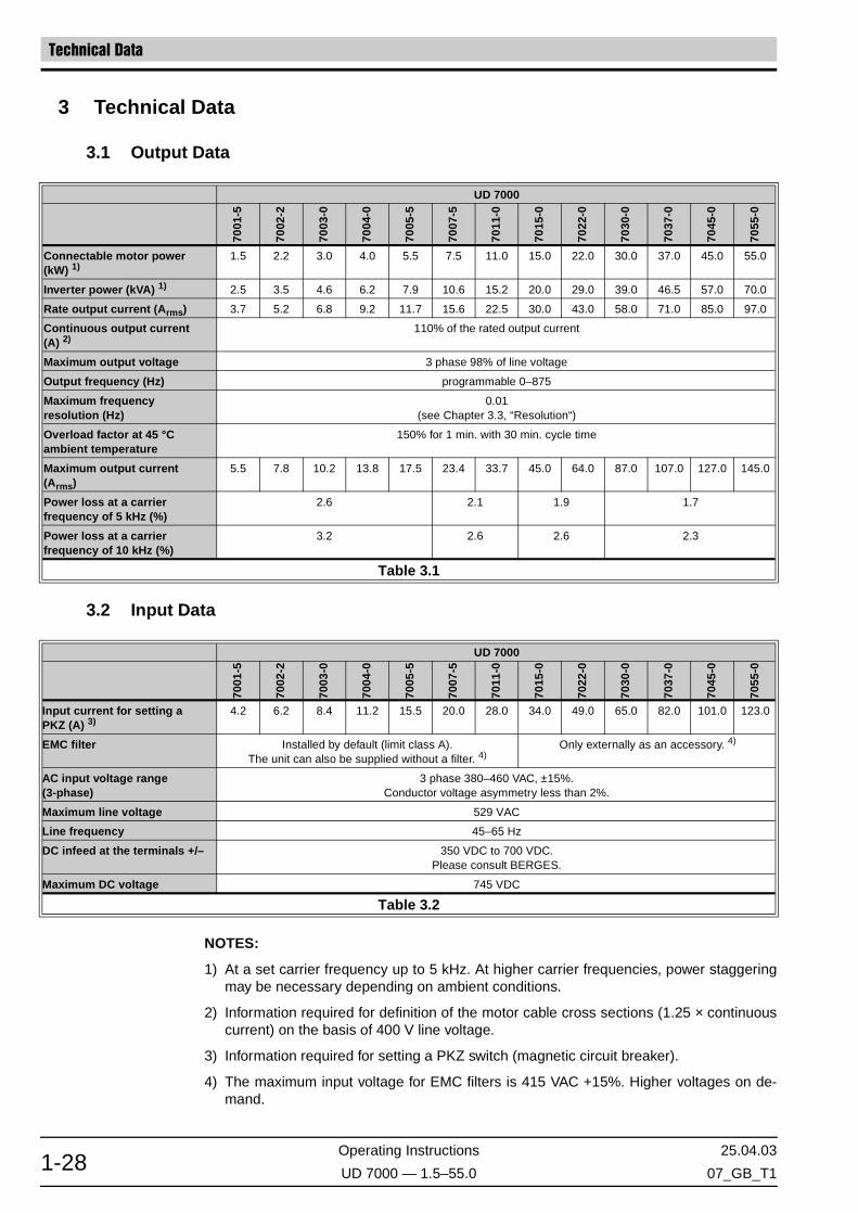
Technical Data
Operating Instructions 25.04.03
UD 7000 — 1.5–55.0 07_GB_T11-28
3 Technical Data
3.1 Output Data
3.2 Input Data
NOTES:
1) At a set carrier frequency up to 5 kHz. At higher carrier frequencies, power staggeringmay be necessary depending on ambient conditions.
2) Information required for definition of the motor cable cross sections (1.25 × continuouscurrent) on the basis of 400 V line voltage.
3) Information required for setting a PKZ switch (magnetic circuit breaker).
4) The maximum input voltage for EMC filters is 415 VAC +15%. Higher voltages on de-mand.
UD 7000
7001
-5
7002
-2
7003
-0
7004
-0
7005
-5
7007
-5
7011
-0
7015
-0
7022
-0
7030
-0
7037
-0
7045
-0
7055
-0
Connectable motor power(kW) 1)
1.5 2.2 3.0 4.0 5.5 7.5 11.0 15.0 22.0 30.0 37.0 45.0 55.0
Inverter power (kVA) 1) 2.5 3.5 4.6 6.2 7.9 10.6 15.2 20.0 29.0 39.0 46.5 57.0 70.0
Rate output current (Arms) 3.7 5.2 6.8 9.2 11.7 15.6 22.5 30.0 43.0 58.0 71.0 85.0 97.0
Continuous output current(A) 2)
110% of the rated output current
Maximum output voltage 3 phase 98% of line voltage
Output frequency (Hz) programmable 0–875
Maximum frequencyresolution (Hz)
0.01(see Chapter 3.3, “Resolution“)
Overload factor at 45 °Cambient temperature
150% for 1 min. with 30 min. cycle time
Maximum output current(Arms)
5.5 7.8 10.2 13.8 17.5 23.4 33.7 45.0 64.0 87.0 107.0 127.0 145.0
Power loss at a carrierfrequency of 5 kHz (%)
2.6 2.1 1.9 1.7
Power loss at a carrierfrequency of 10 kHz (%)
3.2 2.6 2.6 2.3
Table 3.1
UD 7000
7001
-5
7002
-2
7003
-0
7004
-0
7005
-5
7007
-5
7011
-0
7015
-0
7022
-0
7030
-0
7037
-0
7045
-0
7055
-0
Input current for setting aPKZ (A) 3)
4.2 6.2 8.4 11.2 15.5 20.0 28.0 34.0 49.0 65.0 82.0 101.0 123.0
EMC filter Installed by default (limit class A).The unit can also be supplied without a filter. 4)
Only externally as an accessory. 4)
AC input voltage range(3-phase)
3 phase 380–460 VAC, ±15%.Conductor voltage asymmetry less than 2%.
Maximum line voltage 529 VAC
Line frequency 45–65 Hz
DC infeed at the terminals +/– 350 VDC to 700 VDC.Please consult BERGES.
Maximum DC voltage 745 VDC
Table 3.2

25.04.03 Operating Instructions
07_GB_T1 UD 7000 — 1.5–55.0 1-29
Technical Data
3.3 Control Data
3.4 Protective Function
NOTE:
1) Applicable only to AC voltage connections L1, L2, L3 (in the 1.5–11.0 kW power range;external filters in excess of the value).
Modulation method Sinusoidal vector modulation, subharmonic method, trapezoidal control
PWM frequency 2–9 kHz, in 0.01 kHz steps
Setpoint input Setpoint source Resolution
0–10 VDC, 2–10 VDC, ±10 VDC (100 kΩ),0–20 mA, 4–20 mA, ±20 mA (50 Ω load)
10 bits (optionally 12 bits on request)
Keypad: (in the 0 to 99.99 Hz frequency range)(in the 100.0 Hz to Fmax frequency range)
0.01 Hz0.1 Hz
Digital frequency input 0–100 kHz;Master setpoint phase-synchronous fout × 6 or fout × 10
0.01 Hz
7 fixed frequencies can be selected in binary fashion 0.1 Hz
Serial interface RS 485 0.01 Hz
V/Hz characteristic Programmable characteristic with Autoboost or automatic definition
Accel./Decel. times Two sets, which can be switched over, 0.1–999.9 s
Torque limiting Selective in all 4 quadrants, selection from 0–150% Trated possible
Setting possibilities Parameterisation by keypad and RS 485
Field bus Optional
Table 3.3
Pilot indication of DC link voltage Incandescent bulb within the range from 80 VDC to VDC link max.
Earth fault Motor connection terminals resistant to earth faults
Short circuit Motor connection terminals resistant to short circuits
Thermal motor protection I2× t monitoring, motor temperature sensor (optionally normally-closed con-tactor PTC)
Thermal protection of inverter Heat sink temperature monitoring, integrated temperature monitoring in the IGBT module
RFI suppression in accordance with DIN VDE 0875, Part 11
Curve A without external filter. 1)
Curve B with external filter
Voltage in the DC link VDC link min. = 350 VDC to VDC link max. = 750 VDC
Torque limiting Independently programmable in 4 quadrants
Activation lock Protection against automatic starting on activation of the line voltage
Error message Plain-text error display and error consequence
Error history Storage of the last 5 errors, error display
Table 3.4

Technical Data
Operating Instructions 25.04.03
UD 7000 — 1.5–55.0 07_GB_T11-30
3.5 Brake Chopper Power Dissipation
When the motor is used as brake or torque application we recommend the following values(p. ex. for winders and so on):
3.6 Display and Operating Unit
SIZE II SIZE III SIZE IV SIZE V SIZE VI
Inverter model number
7001
-5
7002
-2
7003
-0
7004
-0
7005
-5
7007
-5
7011
-0
7015
-0
7022
-0
7030
-0
7037
-0
7045
-0
7055
-0
Inverter power (kW) 1.5 2.2 3.0 4.0 5.5 7.5 11.0 15.0 22.0 30.0 37.0 45.0 55.0
Maximum continuoustransistor current (Amps)
10.0 10.0 10.0 12.5 12.5 15.0 15.0 50.0 50.0 75.0 75.0 75.0 75.0
Minimum resistance value (Ω)
70 70 70 70 70 50 50 16 16 10 10 10 10
Normal resistance (Ω) 75 75 75 75 75 75 75 20 20 20 20 20 20
Average powerdissipation (Watts)
80 80 80 80 80 150 150 275 275 275 275 275 275
Maximum break time withnominal Inverter power (sec)
7.0 5.0 3.5 2.7 2.0 3.0 2.0 6.0 4.0 3.0 2.5 2.0 1.5
Duty cycle relative to theInverter power (%)
5.0 3.7 2.7 2.0 1.5 2.0 1.4 2.0 1.25 1.0 0.75 0.6 0.5
Table 3.5
SIZE II SIZE III SIZE IV SIZE V SIZE VI
Inverter model number
7001
-5
7002
-2
7003
-0
7004
-0
7005
-5
7007
-5
7011
-0
7015
-0
7022
-0
7030
-0
7037
-0
7045
-0
7055
-0
Inverter power (kW) 1.5 2.2 3.0 4.0 5.5 7.5 11.0 15.0 22.0 30.0 37.0 45.0 55.0
Power dissipation(average) (kW)
1.35 1.98 2.70 3.60 4.95 6.75 9.90 13.50 19.80 27.00 33.30 40.50 49.5
Brake choppercurrent (average) (A)
1.7 2.5 3.5 4.6 6.3 8.7 12.7 17.3 25.4 34.6 42.7 51.9 63.0
Minimum resistant (Ω) 120 60 30 15
Table 3.6
Keypad 8 keys: FWD, REV, STOP, PROG, SHIFT, ENTER, ,
Display Alphanumeric 2-line super-twist LCD display with 16 characters in each line.Display languages: German or English
LED status displays 3 LED’s integrated in the FWD, REV and STOP keys
Control possibilities 1. Keypad2. Control terminals3. Serial interface RS 485
Table 3.7
HINT!

25.04.03 Operating Instructions
07_GB_T1 UD 7000 — 1.5–55.0 1-31
Technical Data
3.7 Parameter Groups
3.8 Mechanical Design and Ambient Conditions
Parameter block 1 Motor data
Parameter block 2 Basic data
Parameter block 3 Setpoint selection (display: Setpoint-select)
Parameter block 4 Frequencies
Parameter block 5 Torque
Parameter block 6 V/Hz characteristic (display: V/f-char)
Parameter block 7 Inverter functions (display: Inverter funct.)
Parameter block 8 Protective functions (display: Security funct.)
Parameter block 9 Binary inputs/outputs (display: Binary In/Outpt)
Parameter block A Analog outputs/SIO (display: Analog Out/SIO)
Parameter block B Speed controller (display: Speed control)
Parameter block C Stepper control (display: Step-control)
Parameter block D Options
Parameter block E Service data II
Parameter block F Service data III (display: Service dataIII)
Parameter block 0 Service data I
Table 3.8
Housing design Bookshelf
Degree of protection IP 20
Installation Installation in a separate housing protected against dust and corrosive vapours
Operating temperature 0 °C to 45 °C
Storage temperature range –20 °C to +60 °C
Humidity <90% relative humidity, no condensation
Vibration Maximum 0.6 g
Altitude level <1000 m without performance reduction
Table 3.9

Technical Data
Operating Instructions 25.04.03
UD 7000 — 1.5–55.0 07_GB_T11-32
3.9 Dimensions
Size II...VI

25.04.03 Operating Instructions
07_GB_T1 UD 7000 — 1.5–55.0 1-33
Technical Data
Dimensions in mm.
Weight in kg.
DIMENSIONS
Size II1.5–5,5 kW
Size III7.5–11 kW
Size IV15–22 kW
Size V30–45 kW
Size VI55 kW
A 100 135 240 345 345
B 395 395 395 – –
C 379 379 379 488 488
D 60 95 180 285 285
E 20 20 30 30 30
F 252 252 252 252 252
G – – – 512 –
H – – – – 716
I – – – 3 3
J – – – 3 –
WEIGHT DATA
Size II Size III Size IV Size V Size VI
5.7 8.2 15.4 26.5 31.0

Drive Variants
Operating Instructions 25.04.03
UD 7000 — 1.5–55.0 07_GB_T11-34
4 Drive Variants
The UD 7000 Series of inverters are general-purpose controllers (static frequency convert-ers) which can be used for low-loss open-loop or closed-loop control of the following motorvariants:
1. Asynchronous motors with squirrel-cage rotor.
2. Asynchronous motors with squirrel-cage rotor and rotational speed feedback (encoderfor feedback of the rotor speed of rotation).
3. Permanent-field synchronous servo-motors with feedback (resolver for feedback of therotor position).
The UD Series of inverters features a high-performance, internal motor control systemwhich controls the connected motor extremely effectively over the entire rotational speedrange. A precise knowledge of the motor data is required so that the internal motor modelsused are able to supply as precise an image as possible of the connected motor. Since theuser will generally be unfamiliar with this data apart from the information on the rating plate,the inverter features Autotest functions (also referred to as Autotuning) which determinethis data automatically. This test must run at least once before placing the drive into oper-ation. Please refer to the Parameter Description, parameter 2A – Test mode (Page 2-45)for further information on this.
4.1 The Motor Drive Data and How it is Measured
Only the data of the motor rating plate is entered in the parameters of “Group 1 – Motor da-ta” for optimum matching of the inverter to the connected motor. Detailed information oncommissioning of the inverter as a function of the selected motor variant can be found inChapter 6, “Commissioning” and in the section on parameter 2A – Test mode.
On drives with feedback, certain other information on the feedback systems used must beentered in “Group B – Speed controller”. If all motor and feedback data has been pro-grammed correctly, other motor feedback data absolutely necessary for optimum control ofthe selected motor variant is determined during the subsequent test run.
4.2 The Asynchronous Motor and Speed Control
The asynchronous motor has proven successful in the field of drive engineering owing toits rugged and low-cost design. When frequency converter technology became cheaperand cheaper and more reliable in the late 70s, it took the place of the closed-loop-controlledDC machine to an ever-increasing extent. Initially, the converter-controlled asynchronousmotor was a low-cost alternative to the closed-loop-controlled DC motor only in the powerrange upwards of 3 kW. Today, it is a fully fledged alternative to the closed-loop-controlledDC motor even as of approx. 100 Watts in view of the fact that power electronic componentsare becoming cheaper and cheaper.

25.04.03 Operating Instructions
07_GB_T1 UD 7000 — 1.5–55.0 1-35
Drive Variants
Constant-flux operation has become the most successful mode of controlling the asynchro-nous motor. This is because, not least, this variant ensures low-loss and optimum torqueoperation over the entire rotational speed range. This can be achieved by maintaining themagnetisation of the motor constant over the entire rotational speed range. In order to en-sure this, the ratio of the applied motor voltage to the current motor frequency (VMot/fMot)must be maintained constantly. Theoretically, this should result in a linear relationship be-tween voltage and frequency. However, as of the point at which the nominal frequency isreached, the motor is operated with rated voltage owing to the limited motor voltage. Theconstant power range starts as of this point. However, at low frequencies, the influence ofthe ohmic winding resistance (resistance of the stator winding) comes more and more tothe fore so that it is necessary to compensate for this voltage drop which weakens the mag-netisation. It is therefore necessary to boost the voltage slightly with respect to its idealcharacteristic (I×R compensation).
Essentially, three methods are used for this magnetisation current control:
1. Characteristic control (VMot/fMot) with I×R compensation.
2. I0 control (reactive power or reactive current control).
3. Field-orientated control with and without feedback (vector control).
These variants which are all integrated in the UD 7000 are discussed below.
4.2.1 V/f-Controlled Operation
The UD 7000 Series of inverters features a high-performance reactive current control sys-tem besides the pure V/f control. Selection is made with parameter 62 – V/Hz characteris-tic selection.
In the case of pure V/f control (setting 2), the various interpolation points are permanentlypreset by the user in order to define the voltage at the related frequency. 5 V/f pairs areavailable (see the illustration below).
In general, presetting points V0, V1 and “Knee” will suffice for a standard asynchronous mo-tor. In the case of special machines, such as reluctance motors for instance, it is frequentlynecessary to specify further intermediate values. The motor manufacturer must then beconsulted for more precise data. Note that this preset characteristic is complied with firmlyunder all load conditions.
Figure 4.1Controlled V/f characteristic

Drive Variants
Operating Instructions 25.04.03
UD 7000 — 1.5–55.0 07_GB_T11-36
One other version of motor control is, as mentioned above, I0 control in combination withslip compensation (parameter 76 – Slip compensation). This type of V/f characteristic con-trol can also be selected with parameter 62 – V/Hz characteristic selection (settings 0, 3,4, 5).
The inverter control system detects the instantaneous value of two motor currents. The thirdphase current can be computed from this. This allows the phase angle of the currents withrespect to the applied voltage to be determined and the currents are then split into activecomponent and reactive component via which it is then possible to conclude the currenttorque and machine flux. The simplified phasor diagram below clearly shows this situation.
It is must be noted that this method makes many simplifications for the complex machinemodel. Influences relating to the rotor are ignored completely for instance.
However, the method has major advantages over purely presetting the V/f ratio. Thus, forinstance, the theoretical load dependence of the V/f ratio is corrected automatically whichleads to a major improvement in the drive characteristics and a reduction in thermal motorloading in the part-load range. This is illustrated in the diagram below.
Figure 4.2Simplified phasor diagram
Figure 4.3Controlled V/f characteristic

25.04.03 Operating Instructions
07_GB_T1 UD 7000 — 1.5–55.0 1-37
Drive Variants
The diagram shows that the V/f characteristic is shifted in parallel upwards (starting fromthe no-load line) as the load increases. The increase in motor voltage in the lower area isperformed automatically whereby the magnitude of the voltage to be added under no loaddepends on the motor data, i.e. correct specification of the motor data and conducting a testrun are of major significance in this operating mode as well (see also Chapter 4.2, “TheAsynchronous Motor and Speed Control”).
Besides automatic readjustment of the V/f ratio (in order to maintain the machine's flux con-stant), the inverter also features slip compensation. It can be connected as required, asmentioned above, and enhances rotational speed stability when subject to load variation.The mode of operation of slip compensation is illustrated in the diagram below:
It is possible to draw conclusions as regards the load-dependent slip of the motor from thetorque-generating current component I1_M. If we know the slip frequency (~fs1;fs2), this isadded to the stator frequency (n1, n2). This greatly enhances rotational speed stability. Themotor is provided with a so-called shunt behaviour. In generator operation, the slip frequen-cy is, of course, subtracted from the stator frequency. Starting from the torque-rotationalspeed characteristic of the asynchronous motor in line operation, this corresponds to a par-allel shift in this characteristic.
Figure 4.4Slip compensation
Caption to illustration
n0 Frequency setpoint
Field-attenuation range
Working range with decreasing maximum torque, resp. working range of constant power
Nominal rotational speed range
Working range with constant torque, resp. working range of in-creased power
n_nom Nominal motor speed (speed of rotation at which the voltage lim-it was reached (f_Knee)
M Torque M1<M2
s Slip s1<s2 (synchronous speed of rotation - rotor speed of rota-tion / synchronous speed of rotation)

Drive Variants
Operating Instructions 25.04.03
UD 7000 — 1.5–55.0 07_GB_T11-38
The essential disadvantage of these open-loop-controlled methods is the fact that thesemethods are all based on static models of the motor. In dynamic operating cases, the op-erating data determined differs greatly from the conditions actually obtaining in the motor.In order to optimise this, it is necessary to use dynamic motor models. In addition, the pre-cise flux obtaining in the motor is computed in these models, i.e. the above-mentioned in-fluences of the rotor on the stator variables are included in computation.
4.2.2 Field-Orientated-Controlled Mode (Vector Control)
Despite all control components, characteristic control does not suffice to achieve a similarlygood control and load behaviour on the asynchronous motor as with a DC motor. The prin-ciple of field-orientated control is used for this purpose. In this case, the field and torque-generating current components are computed precisely and controlled highly dynamically.If this is possible, this provides a control structure which corresponds to that of a DC ma-chine control. There as well, one has one controller for the excitation current and one con-troller for the armature current (torque controller). One talks of magnetisation current andtorque-generating component on the asynchronous machine. A voltage-controlled asyn-chronous machine becomes a current-controlled asynchronous machine.
The fundamental mode of operation of the asynchronous motor which is able to develop atorque only if there is a rotational speed difference between stator field and rotor (slip), in-dicates a problem which cannot be easily solved. As the result of this slip, a current is in-duced in the motor winding and this current, together with the flux in the air gap (rotatingfield), results in a torque. The flux of the stator must now be linked in the air gap with theflux of the rotor in order to obtain the working flux.
The fundamental problem is to detect or compute the flux in the machine from easily meas-urable variables. Only then is it possible to control the torque decoupled from the flux.
The basic physics principle applies here as well:
Since the resultant flux in the machine is now determined not only by the stator-end averageampere conductors per unit of length but since the current also flows in the rotor owing tothe motor's transformer-like design and this current also has a frequency which is not equalto the stator frequency and since this also generates a flux, the ratios become very com-plex. In addition, these rotor influences are also load-dependent. It can be now be easilyimagined that the ratios at the rotor end can be computed exactly only if we know the pre-cise rotor speed of rotation (rotational speed feedback). The conditions in the motor cannow be grasped with the aid of complex mathematical motor models. The data obtainedfrom this can now be transformed to the stator end so that one can construct a precise cur-rent-phasor diagram.
To summarise, the following measuring sensors are also required:
• Current transformer in the motor phases.• Rotational speed feedback on the rotor.
M I φ I φ×(Angle between)sin××∼
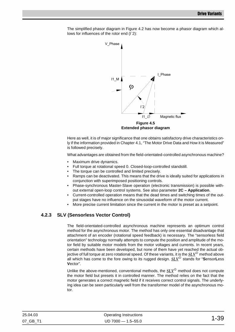
25.04.03 Operating Instructions
07_GB_T1 UD 7000 — 1.5–55.0 1-39
Drive Variants
The simplified phasor diagram in Figure 4.2 has now become a phasor diagram which al-lows for influences of the rotor end (I´2):
Here as well, it is of major significance that one obtains satisfactory drive characteristics on-ly if the information provided in Chapter 4.1, “The Motor Drive Data and How it is Measured”is followed precisely.
What advantages are obtained from the field-orientated-controlled asynchronous machine?
• Maximum drive dynamics.• Full torque at rotational speed 0. Closed-loop-controlled standstill.• The torque can be controlled and limited precisely.• Ramps can be deactivated. This means that the drive is ideally suited for applications in
conjunction with superimposed positioning controls.• Phase-synchronous Master-Slave operation (electronic transmission) is possible with-
out external open-loop control systems. See also parameter 2C – Application.• Current-controlled operation means that the dead times and switching times of the out-
put stages have no influence on the sinusoidal waveform of the motor current.• More precise current limitation since the current in the motor is preset as a setpoint.
4.2.3 SLV (Sensorless Vector Control)
The field-orientated-controlled asynchronous machine represents an optimum controlmethod for the asynchronous motor. The method has only one essential disadvantage thatattachment of an encoder (rotational speed feedback) is necessary. The “sensorless fieldorientation” technology normally attempts to compute the position and amplitude of the mo-tor field by suitable motor models from the motor voltages and currents. In recent years,certain methods have been developed, but none of them have yet reached the actual ob-jective of full torque at zero rotational speed. Of these variants, it is the SLV2 method aboveall which has come to the fore owing to its rugged design. SLV2 stands for “SensorLessVector”.
Unlike the above-mentioned, conventional methods, the SLV2 method does not computethe motor field but presets it in controlled manner. The method relies on the fact that themotor generates a correct magnetic field if it receives correct control signals. The underly-ing idea can be seen particularly well from the transformer model of the asynchronous mo-tor.
Figure 4.5Extended phasor diagram

Drive Variants
Operating Instructions 25.04.03
UD 7000 — 1.5–55.0 07_GB_T11-40
APPROACH:
If the voltage (V_Lh) is maintained constant on the basis of the magnetising inductance, themagnetising current (IM) is also constant. Rotor current (Ir) and magnetising current (IM) arenaturally perpendicular.
This provides all preconditions for optimum control of the motor. In the above equivalent cir-cuit diagram, it can be seen that it is of tremendous importance to calculate with the correctmotor data. Otherwise, the calculation of the field voltage V_Lh leads to incorrect values.The model data such as currents, voltages and rotor rotational speeds, are obtained fromthe SLV2 motor model.
The following block diagram illustrates how this data is obtained from the motor model.
Where: V_Lh = IM × ω × Lh.V_Lh is proportional to ω
Figure 4.6Transformer model of the asynchronous motor (leakage inductances ignored)
Figure 4.7SLV2 implementation in the inverter

25.04.03 Operating Instructions
07_GB_T1 UD 7000 — 1.5–55.0 1-41
Drive Variants
Two vector rotators (1) play a central role, whereby the upper rotator transforms the motorvoltage setpoints from the field coordinate system to the stator coordinate system and thelower rotator performs this transformation in reverse. It can be seen that the voltage V_Lhis calculated for each phase at the stator coordinate end. This provides the motor-internalactual variable of voltage as a function of magnetising inductance LH. These rotating volt-age vectors are transformed back at the field end where they become a DC voltage and areused to compute the angular velocity ω.
This is because:
and, by integration of the angular velocity ω, we obtain the angle of rotation a for controllingthe vector rotators. We can see the basic principle of SLV2 for controlling the motor field:
The field current is preset as a setpoint! The field voltage is computed from this and is pre-set for the motor as a voltage setpoint.
This voltage is calculated back as an actual value from the variables measurable at the mo-tor terminal and, on the basis of this, the angular velocity ω is computed, and this then con-trols the vector rotators after integration. The comparison between field voltage setpointand actual field voltage value is therefore performed indirectly in the vector rotators. α isvaried until VLHact. = VLHsetpoint. A field current controller is not necessary.
Slip computation:
In Figure 4.6 “Transformer model of the asynchronous motor (leakage inductances ig-nored)”, we can directly see that the rotor current IR is proportional to the machine's slip s.If Is and IM are known and V_LH is indirectly measurable as described above, it is possibleto compute s.
We thus know all variables for implementing an optimum, field-orientated control with indi-rect rotational speed measurement.
SLV2 in Practice
This mode of operation is particularly suitable for applications such as the following owingto its high dynamic response:
(1) Vector rotator: a vector rotator is a mathematical method of, for instance, converting the rotating phasor of a periodic quantity to sta-tionary vectors. It is easy to imagine a vector rotator by way of the following example: if we could represent the magnetic field of themotor optically by phasors or pointers and if we view what is happening from the outside, we can see quickly rotating phasors or pointerswhich cannot be easily described. If we now make it possible to position ourselves on a plate turning at the same speed as the field atits centre, we can see a stationary pointer or phasor which can only change its length. The vector rotator corresponds precisely to thisrotating platform.
Application Drive-engineering problem
• Agitators Heavy starting
• Presses Shock loads
• Winders High torque in the lower frequency range
• Injection-moulding machines(screw conveyors)
High peak torques, heavy starting
• Inclined lifts Starting torques
• Metering facilities Constant rotational speed
• Washing machines Constant rotational speed in the lower speed range. Acceleration at the torque limit
• Unwinders Torque-control operation
ωV_Lh
IM LH×( )------------------------=

Drive Variants
Operating Instructions 25.04.03
UD 7000 — 1.5–55.0 07_GB_T11-42
The Limits of SLV2
SLV2 is not yet the optimum solution even at zero rotational speed as the inverter does notissue the voltages which it receives as the preset setpoint owing to switching times anddead times of the output stages. This contamination effect does, of course, occur to a par-ticularly great extent at low voltages (lower frequency range). However, the cost-benefit ra-tio would be disproportionate as regards the improved drive behaviour were one to attemptto compensate for these errors by the use of expensive hardware. Higher-performance fu-ture microprocessors will be able to solve this disadvantage at less cost. Tests have estab-lished the following key performance aspects:
• Rotational speed accuracy: fabs <1% in the correcting range 1:7.• Torque accuracy: fabs <1% in the correcting range 1:5.• Torque at low rotational speeds: 150% at 0.5 Hz (at the motor with 50 Hz nominal fre-
quency).
4.3 The EC Drive
The EC (electronically commutated) motor, as with the asynchronous motor at the statorend, has a three-phase winding. If a rotor with magnet poles is now fitted in the three-phasestator, this produces a synchronous motor.
Here as well – as is the case with asynchronous motors – the interlinked stator currentshould be as perpendicular (orthogonal) as possible on the rotor field in order to maximisethe torque developed. A knowledge of the rotor position as an absolute magnitude is abso-lutely essential in order to guarantee this phase relationship between stator current andmagnetic field position. In general, a resolver, mounted on the rotor, is used for this. Thismotor type as well features the drive-engineering advantages of the field-orientated-con-trolled asynchronous machine. It also features other advantages relating to motor physics,such as:
• Lower rotor moment of inertia. This predestines the motor for positioning tasks.• Lower rotor losses. This results in enhanced efficiency and less rotor heating.• Very low no-load currents.
The UD 7000 inverter allows operation of an EC motor of any manufacturer, whereby thecounter-EMF of the motor should be sinusoidal. This variant achieves best possible truerunning characteristics. Trapezoidal operation is, admittedly, also possible but is not advis-able owing to the aforesaid aspects.
When the motor is commissioned, the motor shaft must be able to turn freely since themounting angle of the resolver is determined in a test run. This involves presetting a sta-tionary voltage vector which pulls the rotor to its optimum position. If this is not followed, themotor is unable to develop its optimum torque and will demand a higher stator current atthe same load.

25.04.03 Operating Instructions
07_GB_T1 UD 7000 — 1.5–55.0 1-43
Abbreviations Used Annex
5 Annex
5.1 Abbreviations Used
The following abbreviations are used in this parameter description:
OE Parameter can be edited on-line.
SC Parameter can be written in the SIO control mode through the serial interface (seedescription “UD 7000 – serial interface”).
SL Parameter is of significance in the version consisting of the standard inverter (Hz/V-controlled amplifier).
FO Parameter is significant in the version consisting of a field-oriented controller withfeedback.
SLV Sensorless vector control SLV2.
EC Parameter is significant in the version consisting of a brushless servo amplifier.
SIO Serial RS 485 interface.

Annex Parameter Structure
Operating Instructions 25.04.03
UD 7000 — 1.5–55.0 07_GB_T11-44
5.2 Parameter Structure
Figure 5.1

25.04.03 Operating Instructions
07_GB_T1 UD 7000 — 1.5–55.0 1-45
Parameter Overview Annex
5.3 Parameter Overview
NOTES:(1)
Various parameters are only available as a function of the current mode.
r-o Read-only parameters are printed in italics and the reference in the tables is abbre-viated to “r-o”.
[S-P] Selection parameter (for adaptation of the inverter functions).
◊ Value range and default values.
GROUP 1 – Motor dataNO. DISPLAY DESCRIPTION RESOLUTION PAGE DEFAULT CUSTOMER
11 Nominal voltage Rated voltage [0.1 V] 2-40 400.0
12 Nom. frequency Rated frequency [0.1 Hz] 2-40 50.0
13 Power factor Power factor [0.01] 2-40
14 Nominal speed Rated speed [min-1] 2-41
15 Nominal power Rated power [0.01 kW] 2-41
16 Nominal current Rated current [0.1 A] 2-41
GROUP 2 – Basic dataNO. DISPLAY DESCRIPTION RESOLUTION PAGE DEFAULT CUSTOMER
21 V/Hz knee Knee frequency [0.1 Hz] 2-42 50.0
22 Boost Boost [0.1%] 2-42 100.0
23 Max. frequency Maximum frequency [0.1 Hz] 2-43 50.0
24 Min. frequency Minimum frequency [0.1 Hz] 2-43 0.0
25 Acceleration #1 Acceleration time 1 [0.1 s] 2-43 3.0
26 Deceleration #1 Deceleration time 1 [0.1 s] 2-43 3.0
27 Acceleration #2 Acceleration time 2 [0.1 s] 2-43 5.0
28 Deceleration #2 Deceleration time 2 [0.1 s] 2-43 5.0
29 Control mode Control mode [S-P] 2-43 13
2A Test mode Test mode [S-P] 2-45 101
2B Tuning mode Adjustment mode [S-P] 2-50 0
2C Application Application [S-P] 2-50 0
2D SW-Reset Software reset [S-P] 2-56 0
GROUP 3 – Setpoint selection (display: Setpoint-select)NO. DISPLAY DESCRIPTION RESOLUTION PAGE DEFAULT CUSTOMER
31 Reference-selec Setpoint selection (frequency setpoint) [S-P] 2-57 0
32 Selection LIM Function of the LIM input [S-P] 2-61 1
33 Ratio frequency Frequency factor [0.01%] 2-62 100.00
34 Fact.LIM analog Scaling factor ALIM for analogue LIM input [0.1%] 2-63 10.0
35 Calibr.LIM digi Calibration digital LIM input with factor DLIM [0.1 Hz/kHz] 2-63 2.0
36 Pulse numberLIM Pulse number of LIM input [1] 2-63 6
37 Dir.master-ref. Direction of rotation, master setpoint [S-P] 2-65 0
38 min Ratio freq. Low frequency factor limit [0.01%] 2-65 0.00
39 max Ratio freq. High frequency factor limit [0.01%] 2-66 105.00
3A F-EXT1 (SIO) External frequency setpoint 1 [0.01 Hz] (1) 2-66 0.00
3B F-EXT2 (SIO) External frequency setpoint 2 [0.01 Hz] (1) 2-66 80.00
3C Time. VIN/CIN Filtering time constant VIN/CIN input [2x ms] 2-66 4
3D Time. LIM Filtering time constant LIM input [2x ms] 2-66 4
3E Pulse no. ST4 Pulse number ST4-output [1] 2-66 10
3F Speed Reference Frequency setpoint on the basis of ramp [0.1 Hz] 2-67 r-o
(1) In the “high frequency” application profile: unit [0.1 Hz].

Annex Parameter Overview
Operating Instructions 25.04.03
UD 7000 — 1.5–55.0 07_GB_T11-46
GROUP 4 – FrequenciesNO. DISPLAY DESCRIPTION RESOLUTION PAGE DEFAULT CUSTOMER
41 Preset speed #1 Fixed frequency 1 [0.1 Hz] 2-67 5.0
42 Preset speed #2 Fixed frequency 2 [0.1 Hz] 2-67 20.0
43 Preset speed #3 Fixed frequency 3 [0.1 Hz] 2-67 40.0
44 Preset speed #4 Fixed frequency 4 [0.1 Hz] 2-67 60.0
45 Preset speed #5 Fixed frequency 5 [0.1 Hz] 2-67 0.0
46 Preset speed #6 Fixed frequency 6 [0.1 Hz] 2-67 0.0
47 Skip band Hysteresis band for blocking frequencies [0.1 Hz] 2-69 1.0
48 Skip freq. #1 Blocking frequency 1 [0.1 Hz] 2-69 0.0
49 Skip freq. #2 Blocking frequency 2 [0.1 Hz] 2-69 0.0
4A Skip freq. #3 Blocking frequency 3 [0.1 Hz] 2-69 0.0
4B Skip freq. #4 Blocking frequency 4 [0.1 Hz] 2-69 0.0
GROUP 5 – TorqueNO. DISPLAY DESCRIPTION RESOLUTION PAGE DEFAULT CUSTOMER
51 Select.TLim.MFo Torque limit selection, right rotation, motor operation [S-P] 2-69 0
52 Select.TLim.MRe Torque limit selection, left rotation, motor operation [S-P] 2-69 0
53 Select.TLim.GFo Torque limit selection, right rotation, generator operation [S-P] 2-69 0
54 Select.TLim.GRe Torque limit selection, left rotation, generator operation [S-P] 2-69 0
55 Torque-lim(LIM) Torque factor LIM input [0.1%] 2-70 100.0
56 T-Offset-Acc. Additional acceleration torque [0.1%] 2-70 0.0
57 T-Offset-Dec. Additional deceleration torque [0.1%] 2-70 0.0
58 TLimit-Mot-FWD Torque limit, right rotation, motor operation [0.1%] 2-70 100.0
59 TLimit-Mot-REV Torque limit, left rotation, motor operation [0.1%] 2-70 100.0
5A TLimit-Gen-FWD Torque limit, right rotation, generator operation [0.1%] 2-70 100.0
5B TLimit-Gen-REV Torque limit, left rotation, generator operation [0.1%] 2-70 100.0
5C SIO-Torq.limit External torque limit [0.1%] 2-70 100.0
5D Start torque Starting torque [0.1%] 2-71 130.0
5E Ref.torque(VIN) Torque setpoint factor [0.1%] 2-71 100.0
5F Gain TCtrl-ramp Gain (VRm), acceleration control (ramp), torque [0.1%] 2-71 200.0
GROUP 6 – V/Hz characteristic (display: V/f-char)NO. DISPLAY DESCRIPTION RESOLUTION PAGE DEFAULT CUSTOMER
61 Autoboost Autoboost [S-P] 2-72 1
62 V-Hz selector V/Hz characteristic selection [S-P] 2-73 3
63 Curr. DC-brake DC brake current [0.1 A] 2-74
64 DC-brake time DC brake time [0.1 s] 2-74 1.0
65 Freq. DC On DC brake switch-on frequency [0.1 Hz] 2-74 0.5
66 Setuptime field Field build-up time [0.1 s] 2-74 0.5
67 V/f-Char. V0 V/Hz characteristic, voltage V0 [0.1 V] 2-75 0.0
68 V/f-Char. V1 V/Hz characteristic, voltage V1 [0.1 V] 2-75 100.0
69 V/f-Char. V2 V/Hz characteristic, voltage V2 [0.1 V] 2-75 150.0
6A V/f-Char. V3 V/Hz characteristic, voltage V3 [0.1 V] 2-75 200.0
6B Max. Voltage Cut-in point of voltage limitation control [0.1%] 2-76 98.0
6C Min.excitation Minimum excitation [0.1%] 2-76 33.0
6D Setup fld.activ Field build-up time activation [S-P] 2-76 1
6E Filt.Time.FWeak Filter field weakening [1 ms] 2-76 100
6F Increments Increment [1] 2-76 1

25.04.03 Operating Instructions
07_GB_T1 UD 7000 — 1.5–55.0 1-47
Parameter Overview Annex
GROUP 7 – Inverter functions (display: Inverter funct.)NO. DISPLAY DESCRIPTION RESOLUTION PAGE DEFAULT CUSTOMER
71 Start/Stop opt. Start and Stop options [S-P] 2-77 0
72 Ramp selector Ramp function selection [S-P] 2-78 0
73 Ramp. smooth Drag time [0.1 s] 2-79 0.1
74 Sel. power fail Power failure response [S-P] 2-79 2
75 Gain UDC-Ctrl. DC link voltage control gain VDC link [0.1%] 2-80 500.0
76 Slip compensat. Slip compensation [S-P] 2-80 0
77 Gain slip-comp. Slip compensation setting [0.1%] 2-81 100.0
78 Language Language [S-P] 2-81 0
79 PWM frequency PWM frequency [0.01 kHz] 2-81 4.50
7A Power Chopp-R Braking resistor power [0.01 kW] 2-81 0.08
7B Sped motpot.Inc Increment motor potentiometer speed [0.1 s] 2-82 10.0
7C Sped motpot.Dec Decrement motor potentiometer speed [0.1 s] 2-82 10.0
7D heating time R Permissible heating time of braking resistor [1 s] 2-83 2
7E brake resistor Connected braking resistor [1 Ω] 2-83 20/75
7F PWM mode Control method [S-P] 2-83 1
GROUP 8 – Protective functions (display: Security funct.)NO. DISPLAY DESCRIPTION RESOLUTION PAGE DEFAULT CUSTOMER
81 Selector MOL MOL input function selection [S-P] 2-83 2
82 MOL-Input MOL input display [1%] 2-84 r-o
83 Restart Select. Restart after fault definition [Binary] 2-84 0000
84 Number Restart Number of restarts [1] 2-85 0
85 Delay Restart Restart delay [0.1 s] 2-85 10.0
87 Access code Password [1] 2-85 0
88 Therm.timeconst Thermal motor time constant [1 min] 2-85 15
89 I2t-Limit(Warn) I2t warning threshold [0.1%] 2-86 115.0
8A I2t-Limit I2t error threshold [0.1%] 2-86 120.0
8B Max.Ramp.Delay Maximum permissible ramp extension in the event of stop [1%] 2-86 200
8C T.Stop observer Current monitoring time tout for stop ramp [0.1 s] 2-87
8D Refer. ST-Outp. Reference value for load-dependent switching of control outputs [0.1%] 2-88 0.0
8E Watch Speed Selection speed control [1] 2-88 0
GROUP 9 – Binary inputs/outputs (display: Binary In/Outpt)NO. DISPLAY DESCRIPTION RESOLUTION PAGE DEFAULT CUSTOMER
91 Inputs FWD/REV Function of inputs FWD and REV [S-P] 2-89 1
92 Aux. output #1 Output ST1 function selection [S-P] 2-89 3
93 Aux. output #2 Output ST2 function selection [S-P] 2-89 102
94 Aux. output #3 Output ST3 function selection [S-P] 2-89 10
95 Aux. output #4 Output ST4 function selection [S-P] 2-89 115
96 Auxiliary relay Relay output function selection [S-P] 2-89 101
97 Outp.SIO-Contrl Control of binary outputs through SIO [Binary] 2-92 0
98 Input Run/Jog Run/Jog input function selection [S-P] 2-92 0
99 Input PS1 PS1 input function selection [S-P] 2-93 4
9A Input PS2 PS2 input function selection [S-P] 2-94 1
9B Input PS3 PS3 input function selection [S-P] 2-96 6
9C Status Inputs Status of binary inputs [Binary] 2-99 r-o
9D Status Outputs Status of binary outputs [Binary] 2-100 r-o
9F Inpt.H/L-active High/Low active binary input selection [S-P] 2-100 1

Annex Parameter Overview
Operating Instructions 25.04.03
UD 7000 — 1.5–55.0 07_GB_T11-48
GROUP A – Analog outputs/SIO (display: Analog Out/SIO)NO. DISPLAY DESCRIPTION RESOLUTION PAGE DEFAULT CUSTOMER
A1 Meter output #1 Analog output MET1 selection [S-P] 2-101 1
A2 Meter output #2 Analog output MET2 selection [S-P] 2-101 4
A3 Factor Analog1 MET1 factor [0.1%] 2-101 100.0
A4 Factor Analog2 MET2 factor [0.1%] 2-102 100.0
A5 Offset Analog2 MET2 offset [0.1%] 2-102 0.0
A6 Reference MET Reference value for the analog output [1] 2-102 500
A7 FilterTime Gr.0 Filtering time constant of displayed values in parameter group 0 [2x ms] 2-103 6
A8 SIO-Baudrate Baud rate SIO selection [S-P] 2-103 4
A9 SIO-Address Slave address of the inverter for SIO operation [0–31] 2-103 0
AA SIO-Protocol SIO protocol [S-P] 2-104 1
AB SIO-Timeout SIO operation time-out [1 s] 2-104 0
AC SIO-Errors SIO operation error messages [Binary] 2-104 r-o
AD SIO-Commands Inverter control commands in SIO mode [Binary] 2-105 0
GROUP B – Speed controller (display: Speed control)NO. DISPLAY DESCRIPTION RESOLUTION PAGE DEFAULT CUSTOMER
B1 P-gain Speed controller gain [1] 2-105 100
B2 I-gain Reset time of speed controller [1 ms] 2-105 500
B3 Gain boost Speed controller gain boosting factor [0.1] 2-106 1.1
B4 Maxfreq.gain-b. Speed controller gain boosting end frequency [0.1 Hz] 2-106 0.0
B5 Holding control Holding control [S-P] 2-107 0
B7 Rel.drag.dist. Specific holding controller following error [0.001%] 2-107 0.100
B8 TN pos.cntrl Specific position control reset time [2x] 2-108 0
BA Pole pairs Rslv Resolver pole pair number [1] 2-108 1
BB Angle (mech.) Motor shaft angle [0.1°] 2-108 r-o
BC Off.angle senso Angle sensor installation offset [8000–7FFFH] 2-108 0000
BD Dir.angle senso Angle sensor direction of rotation [S-P] 2-109 0
BE Lines Encoder Number of encoder lines [1] 2-109 1024
BF Angle (Sensor) Resolver measured angle [0–FFFFH] 2-109 r-o
GROUP C – Stepper control (display: Step-control)NO. DISPLAY DESCRIPTION RESOLUTION PAGE DEFAULT CUSTOMER
C2 Step-control Enable step-by-step control application [S-P] 2-110 0
C3 Input step Step number for parameter input [1] 2-110 0
C4 Condition Input Input condition 2-110 0
C5 Condition Outpt Output condition 2-110 0
C6 Parameter-no. 1 Parameter number 1 [1] 2-110 0
C7 Param. value 1 Parameter value 1 [1] 2-110 0
C8 Parameter-no. 2 Parameter number 2 [1] 2-110 0
C9 Param. value 2 Parameter value 2 [1] 2-110 0
CA Parameter-no. 3 Parameter number 3 [1] 2-110 0
CB Param. value 3 Parameter value 3 [1] 2-110 0
CC Delay time Waiting time [0.001 s] 2-110 0
CD Actual step Current step [1] 2-110 0
CE Mask pin Mask for terminal signals 2-110 0
CF Step-ctrl input Input for terminal signals 2-110 0
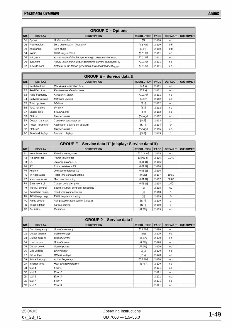
25.04.03 Operating Instructions
07_GB_T1 UD 7000 — 1.5–55.0 1-49
Parameter Overview Annex
GROUP D – OptionsNR. DISPLAY DESCRIPTION RESOLUTION PAGE DEFAULT CUSTOMER
D1 Option Option number [1] 2-110 r-o
D2 F-zero pulse Zero pulse search frequency [0.1 Hz] 2-110 0.5
D3 Zero angle Zero angle [0.1°] 2-110 0.0
D4 sigma Total stray factor σ [0.01%] 2-111 r-o
D5 id/Id,nom Actual value of the field-generating current component id [0.01%] 2-111 r-o
D6 iq/Iq,nom Actual value of the torque-generating current component iq [0.01%] 2-111 r-o
D7 iq,set/Iq,nom Setpoint of the torque-generating current component iq,set [0.01%] 2-111 r-o
GROUP E – Service data IINR. DISPLAY DESCRIPTION RESOLUTION PAGE DEFAULT CUSTOMER
E1 Real.Acc.time Realised acceleration time [0.1 s] 2-111 r-o
E2 Real.Dec.time Realised deceleration time [0.1 s] 2-111 r-o
E3 Ratio frequency Frequency factor [0.01%] 2-111 r-o
E4 SoftwareVersion Software version [0.01] 2-112 r-o
E5 Total op. time Lifetime [1 h] 2-112 r-o
E6 Total run time On time [1 h] 2-112 r-o
E7 Enable time Enabling time [1 h] 2-112 r-o
E8 Status Inverter status [Binary] 2-112 r-o
E9 Custom para.set Customer parameter set [S-P] 2-113 1
EA Reset Parameter Application-dependent defaults [S-P] 2-114 0
EB Status 2 Inverter status 2 [Binary] 2-115 r-o
EC Standarddisplay Standard display [S-P] 2-115 1
GROUP F – Service data III (display: Service dataIII)NR. DISPLAY DESCRIPTION RESOLUTION PAGE DEFAULT CUSTOMER
F1 Nom.Power Inv Rated inverter power [0.01 kW] 2-115 r-o
F2 Filt.power fail Power failure filter [0.001 s] 2-115 0.040
F3 R1 Stator resistance R1 [0.01 Ω] 2-116
F4 R2 Rotor resistance R2 [0.01 Ω] 2-116
F5 Xsigma Leakage reactance Xσ [0.01 Ω] 2-116
F6 Tr-Adaptation Rotor time constant setting [0.1%] 2-117 100.0
F7 Main reactance Main reactance Xh [0.01 Ω] 2-117 30.00
F8 Gain I-control Current controller gain [0.01 Ω] 2-118 1.00
F9 TN/TA I-control Specific current controller reset time [1] 2-118 50
FA Dead-time comp. Dead time compensation [1] 2-118 1
FB PWM freq.chnge. PWM frequency slaving [1] 2-119 0
FC Ramp control Ramp acceleration control (torque) [S-P] 2-119 1
FD Torq.limitation Torque limiting [S-P] 2-119 1
FE Excitation Excitation [0.1%] 2-119 r-o
GROUP 0 – Service data INR. DISPLAY DESCRIPTION RESOLUTION PAGE DEFAULT CUSTOMER
01 Outpt frequency Output frequency [0.1 Hz] 2-120 r-o
02 Output voltage Output voltage [1%] 2-120 r-o
03 Output current Output current [0.1 A] 2-120 r-o
04 Load torque Output torque [0.1%] 2-120 r-o
05 Output power Output power [0.1%] 2-120 r-o
06 Line voltage Line voltage [1 V] 2-120 r-o
07 DC voltage DC link voltage [1 V] 2-120 r-o
09 Actual freqncy. Actual frequency [0.1 Hz] 2-120 r-o
0A Inverter temp. Heat sink temperature [1 °C] 2-120 r-o
0B fault 1 Error 1 2-121 r-o
0C fault 2 Error 2 2-121 r-o
0D fault 3 Error 3 2-121 r-o
0E fault 4 Error 4 2-121 r-o
0F fault 5 Error 5 2-121 r-o

Annex Error States
Operating Instructions 25.04.03
UD 7000 — 1.5–55.0 07_GB_T11-50
5.4 Error States
If the PROG, SHIFT or ENTER key is pressed, the message is reset on the ABE (displayand operator-control unit). Acknowledgement of the error message does not cancel thecause of the error. Errors may be also still be pending after reset.
5.4.1 Normal Handling of Error States
In certain circumstances, the inverter may assume an error state. The occurrence of sucha state can be reported through relay or transistor outputs (parameters 92–96, setting x01).The output is activated if an error occurs. When the cause of the error disappears, the errorsignalling output becomes inactive with deactivation of drive enabling; the drive is ready foroperation.
5.4.2 Handling of Error States with the “Acknowledge Error State” Function
When a binary input R/J, PS1–PS3 is programmed with the “Acknowledge error state” func-tion, an error state always continues to exist until the cause of the error has been remedied,drive enabling has been cancelled and the binary input “Acknowledge error state” is acti-vated. Thus, in a system with several inverters, it is possible to cancel all drive enabling sig-nals in the event of a malfunction occurring and to nevertheless locate the defective inverterthrough the relay or transistor output.
In the basic state, the binary input must be deactivated as otherwise the inverter cannot bestarted. In the event of an error, drive enabling must first be cancelled and only then theinput activated. The binary input should not be cancelled until the error state is no longerindicated by the inverter.
FAULTNO.
MESSAGE DESCRIPTION
0 Local stop Keypad Stop button has been pushed in the remote mode
1 Min. net voltage AC Line voltage to low
2 Overtemperature Heat sink temperature to high
3 Overcurrent Over current in the output stage
4 Error PWM PWM Fault
5 MOL contact open MOL contact open/Motor temperature to high
6 Overvoltage DC-L DC Bus voltage to high
7 DC-Link failure DC Bus voltage out of limit during power up
8 Speed observer Speed above limit or control error too high (see parameter 8E)
9 Dyn.brake-overld DB duty cycle above limit
10 UndervoltageDC-L DC Bus voltage to low
11 Option The option board is not plug in for the selected application
12 Auto-Stop The auto stop control has been detect
13 SIO-Timeout Series communication is disconnect
14 Position sensor Motor feedback is disconnect
15 I²t-Watch The electronic motor protection has been exceeded
WARNING MESSAGES:
16 Overtemperature Warning: Heat sink temperature to high
HINT!

25.04.03 Operating Instructions
07_GB_T1 UD 7000 — 1.5–55.0 1-51
Error States Annex
17 MOL contact Warning: Motor temperature exceeded
18 Dyn.brake 80% Warning: DB resistor overload
19 Motor synchron. Warning: Speed synchronization in an running motor doesn't work
21 I2t Warning: The electronic motor protection has been exceeded
22 R1-Measuring Warning: R1 measuring out of limit
23 Overcurrent Warning: Overcurrent limit would been reached
25 Cable cap. The cable capacitor is to high
26 Xs-Measuring Warning: Xσ-Measuring is out of limit
27 Set disconn Warning: In case of setting the parameter 31 to 2 or 5 you get this message if the set-point is below 2 V/4 mA
28 Sensor off. Warning: The measuring of the mounting offset is fail
29 Zero pulse Warning: No zero pulse is found
30 CAN-Controller No can controller found
31 Min. excitation Warning: Minimum limit of excitation is reached
THE FOLLOWING INTERNAL FAULTS ARE DISPLAYED ONLY AFTER POWER UP:
32 Watchdog reset Watchdog-Fault
33 Ill.trap number Unknown trap-number
34 Ill.Ext.Bus Acc. Unknown external Bus-access
35 Ill.Instr.Access Unknown instruction access
36 Ill.Word Op.Acc. Unknown word access
37 Protection Fault Protection fault
38 Undefined Opcode Undefined op-code
39 Stack Underflow Stack-underflow
40 Stack Overflow Stack-overflow
41 Nonmaskable Int. Nonmaskable interrupt
FAULTNO.
MESSAGE DESCRIPTION

Annex Error States
Operating Instructions 25.04.03
UD 7000 — 1.5–55.0 07_GB_T11-52


BERGES electronic GmbHIndustriestraße 13 • D–51709 Marienheide-RodtPostfach 1140 • D–51703 MarienheideTel. (0 22 64) 17-0 • Fax (0 22 64) 1 71 26http://www.berges.de • e-mail: [email protected]