UCLA SuperMileage Vehicle - Weeblyjoerlee.weebly.com/uploads/4/3/5/3/43538707/smv... · vehicle...
29
UCLA Supermileage Vehicle Team Leadership: Joseph Lee, President & Project Manager Joshua Chen, Chief Technical Officer Tony Wanket, Vice President & Powertrain Andrew Hwang, Structures Brandon Yang, Steering David Cropp, Integration Oscar Santana, Electrical & EFI Faculty Advisor: Professor Christopher S. Lynch Abstract: The following proposal documents the intended design goals of the 2014 Supermileage Vehicle Team at the University of California at Los Angeles (UCLA). The Supermileage Vehicle is a project that strives to develop a prototype vehicle that seeks the highest attainable fuel efficiency using an internal combustion engine and transporting a single driver. The new 2014 model is a new iteration of the 2013 model, which was the first composite monocoque ever created by the UCLA team. The 2014 model uses a similar carbon fiber and aluminum flexcore composite monocoque design, but improves the old model in a number of different areas, including a lighter body design, a more reliable overhead valve engine modification, and an in- house developed electric fuel injection system. The goal of this year’s model is to improve the vehicle fuel efficiency by over 200% and break the 1000 MPG mark. Design Report Model: 2014 Editor: Joseph Lee Copyright © 2014 SAE International
Transcript of UCLA SuperMileage Vehicle - Weeblyjoerlee.weebly.com/uploads/4/3/5/3/43538707/smv... · vehicle...

UCLA Supermileage Vehicle Team Leadership:
Joseph Lee, President & Project Manager
Joshua Chen, Chief Technical Officer
Tony Wanket, Vice President & Powertrain
Andrew Hwang, Structures
Brandon Yang, Steering
David Cropp, Integration
Oscar Santana, Electrical & EFI
Faculty Advisor:
Professor Christopher S. Lynch
Abstract:
The following proposal documents the intended design goals of the 2014 Supermileage Vehicle Team at the University of California at Los Angeles (UCLA). The Supermileage Vehicle is a project that strives to develop a prototype vehicle that seeks the highest attainable fuel efficiency using an internal combustion engine and transporting a single driver. The new 2014 model is a new iteration of the 2013 model, which was the first composite monocoque ever created by the UCLA team. The 2014 model uses a similar carbon fiber and aluminum flexcore composite monocoque design, but improves the old model in a number of different areas, including a lighter body design, a more reliable overhead valve engine modification, and an in-house developed electric fuel injection system. The goal of this year’s model is to improve the vehicle fuel efficiency by over 200% and break the 1000 MPG mark.
Design Report Model: 2014
Editor: Joseph Lee Copyright © 2014 SAE International

UCLA SuperMileage Vehicle 2014
2
Figure 1: Team Photo with Vehicle at Shell Eco Marathon 2013
1. Introduction
The UCLA Supermileage Team introduced a composite monocoque vehicle for the first time in team history in 2013. Though this new design involved calculated risk and a complete deviation from the team’s traditional aluminum tubed chassis, the monocoque design was largely a success for the team. At the SAE Supermileage Competition 2013, the new vehicle achieved 407 MPG, which resulted in an overall 8th place finish. The 2014 model will continue this ambitious trajectory by aiming to improve upon the 2013 model. Though the team considered 407 MPG successful, the team also observed numerous areas the vehicle can be improved for even greater fuel efficiency.
The new monocoque created a new set of challenges the team had never experienced before. The team encountered problems with effectively mounting components and inability to have a reliable fuel injection system. Since the 2013 model represented uncharted territory, the UCLA team took extensive care in the fabrication of the composite monocoque. However, this resulted in a delay in the vehicle production timeline. As a result, production of other systems including powertrain, steering, and wheel mounts became slightly neglected. Now with a larger team and experienced leadership, the team is much more confident in the fabrication process of the monocoque. The team was then able to devote the much needed time to refine the remaining systems.
The remainder of this report will outline each subsystem and the engineering decisions behind each design and modification.
Design Considerations: Weight: A lighter vehicle will require
less force, and therefore less fuel, to accelerate
Aerodynamics: Less drag reduces the deceleration of the vehicle
Engine efficiency: Modifying the engine can increase its thermal efficiency
Drivability: Improved steering control and visibility allow the driver to drive more efficiently
UCLA SuperMileage Vehicle 2014
3
Contents: Abstract: ........................................................................................................................................................ 1
1. Introduction .......................................................................................................................................... 2
2. List of Figures ........................................................................................................................................ 4
3. Basic Vehicle Configuration .................................................................................................................. 5
4. Vehicle Body .......................................................................................................................................... 6
4.1 Design ............................................................................................................................................ 6
4.2 Structural Analysis ......................................................................................................................... 7
4.3 Fabrication .................................................................................................................................... 7
4.4 Windows ....................................................................................................................................... 8
5. Suspension and Running Gear .............................................................................................................. 9
5.1 Steering System ............................................................................................................................ 9
5.2 Wheel Mounts ............................................................................................................................ 11
6. Engine .................................................................................................................................................. 12
6.1 Overview ..................................................................................................................................... 12
6.2 Overhead Valve Modification ..................................................................................................... 12
6.3 Electronic Fuel Injection System ................................................................................................. 13
7. Powertrain Configuration ................................................................................................................... 15
7.1 Clutch .......................................................................................................................................... 15
7.2 Gear Ratio ................................................................................................................................... 16
7.3 Rear Gear and Spider .................................................................................................................. 16
8. Brake System ....................................................................................................................................... 17
9. Driver Safety and Comfort Features ................................................................................................... 18
10. Performance Estimates ....................................................................................................................... 20
11. Cost Estimate and Manufacturing Methods ....................................................................................... 23
12. Conclusion ........................................................................................................................................... 25
Appendix ..................................................................................................................................................... 26
A. Electric Fuel Injection Components ............................................................................................ 26
B. Engine Control Circuit Diagram ................................................................................................... 27
C. Itemized Cost Estimate ............................................................................................................... 28
UCLA SuperMileage Vehicle 2014
4
2. List of Figures
Figure 1: Team Photo with Vehicle at Shell Eco Marathon 2013 ................................................................. 2
Figure 2: Basic Design, Isometric View ......................................................................................................... 5
Figure 3: Basic Design, Orthogonal (Right) View .......................................................................................... 5
Figure 4: Basic Vehicle Dimensions ............................................................................................................... 6
Figure 5: Ribbed Flexcore Design, Isometric View ........................................................................................ 7
Figure 6: Completed Body Layup .................................................................................................................. 8
Figure 7: Steering Handle Connections ......................................................................................................... 9
Figure 8: Steering Knuckle & Ackermann Bar ............................................................................................. 10
Figure 9: Cross Sectional View of Steering Knuckle .................................................................................... 10
Figure 10: Steering Knuckle FEA Analysis .................................................................................................... 10
Figure 11: Front Wheel Mount FEA Analysis .............................................................................................. 11
Figure 12: Rear Wheel Mount FEA Analysis ................................................................................................ 11
Figure 13: OHV Adaptor Plate & Stock Engine Block .................................................................................. 12
Figure 14: Briggs & Stratton 550 OHV Head ............................................................................................... 13
Figure 15: Sainsmart Mega 2560 ................................................................................................................ 14
Figure 16: Fuel Schematic Diagram ............................................................................................................. 14
Figure 17: Hortman Briggs X5 Junior 1 Disk Clutch ..................................................................................... 15
Figure 18: Briggs & Stratton Power and Torque ......................................................................................... 15
Figure 19: Rear Gear Spider (“Ninjastar”) ................................................................................................... 16
Figure 20: Rear V-Brake Mount .................................................................................................................. 17
Figure 21: Schematic of working V-brake ................................................................................................... 17
Figure 22: Foam Male Mold ........................................................................................................................ 23

UCLA SuperMileage Vehicle 2014
5
Figure 3: Basic Design, Orthogonal (Right) View Figure 2: Basic Design, Isometric View
3. Basic Vehicle Configuration
The 2014 design is a three-wheeled, rear-wheel drive vehicle. The body is a carbon-fiber and aluminum flexcore composite. For non-loadbearing sections, the body is made up of just carbon-fiber
sheets. Within the body, there are two main sections that is separated by the firewall. The front serves as the cockpit, which houses the driver. The driver lays on his/her back on the vehicle body during vehicle operation. The rear section of the body serves as the engine compartment. The vehicle is powered by a 3.5 gross horsepower Briggs and Stratton engine via direct drive to the rear wheel. The driver operates the vehicle via two levers which lay at his side. The movement of the levers facilitate the steering angles of the front wheels by a system of connecting rods. The levers also includes mounting locations for the vehicle controls for the rear brake, throttle, starter motor, and a kill switch that grounds the magneto of the engine. A foot pedal at the front of the cockpit operates the front brakes. All vehicle components are housed within a carbon fiber fairing, including the front and rear wheels. The vehicle has a large front window and two pairs of side windows.
Dimensions: Track width: 30.4” Max Width of fairing: 40.5” Wheelbase: 87” Total Length: 108" Ground Clearance: 4.5" Gear Ratio: 1:7 (15T:105T) Body weight (with axle assembly): 29lbs Estimated Overall weight: 95 lbs Top Speed: ~ 30mph
Component Summary:
Body: Carbon fiber – Aluminum flexcore composite
Battery: 12V LiFePo4, 4 Cell Engine: 3.5 hp Briggs & Stratton, 148cc Windows: Polycarbonate, 1/16” Front Brakes: Avid Juicy 7 Hydraulic Disc Rear Brake: Tektro Linear-pull V-Brake Front Wheels: 20” BMX (405mm ERD) Rear Wheel: 20” BMX (405mm) Left Hand Drive Tires: Michelin Prototype Fuel: Gasoline

UCLA SuperMileage Vehicle 2014
6
4. Vehicle Body
4.1 Design The body of the 2014 vehicle features a monocoque design, which serves two purposes: bears all structural loads on the vehicle and reduces drag. The body is split into two sections, top and bottom. Both top and bottom feature composite sandwich technology. By carefully considering the shape of the fairing surface, the drag force on the vehicle can be reduced while keeping the interior capacity at a maximum for driver comfort. The vehicle body was designed using Solidworks. It was then fabricated by members of the team with the help of Performance Composites in Compton, CA. Over the past few years, UCLA team members have determined the “teardrop” design as the optimum balance of aerodynamics and interior space. This year, the UCLA team is using the same body shape as the 2013 model.
The final body shape required several drafting iterations in attempts to minimize the drag coefficient. Solidworks’ fluid flow analysis calculated a drag coefficient of 0.09, assuming mixed flow boundary conditions in ambient air flowing over the form at 30 mph, which is the maximum speed the vehicle will travel. Several allowances were made for design and production flaws. For one, the vehicle is much wider than necessary, having a frontal area of 836 square inches. This allows for extra room with front wheel placement, steering components, and the driver’s legs.
Design Goals
Minimize drag forces on vehicle Fulfill all safety requirements Optimize design: Reduce weight in
order to increase efficiency Utilize proper and professional
engineering techniques Maintain driver visibility with windows Minimize manufacturing costs
Figure 4: Basic Vehicle Dimensions
UCLA SuperMileage Vehicle 2014
7
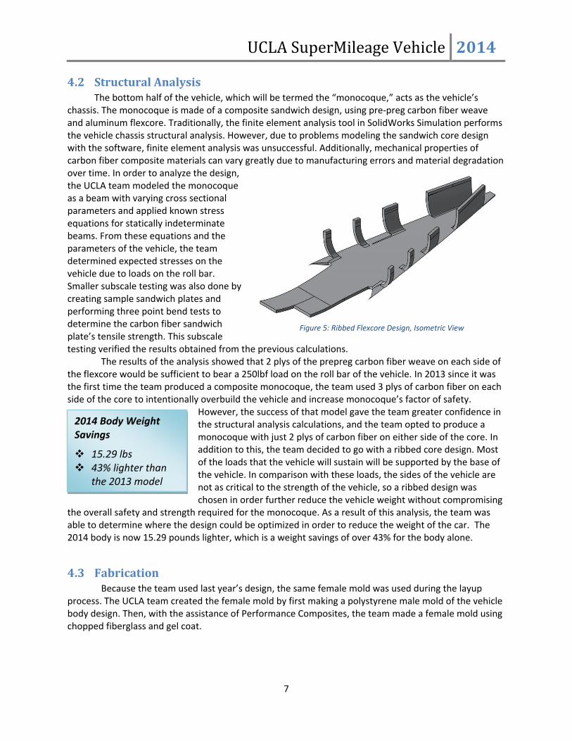
4.2 Structural Analysis The bottom half of the vehicle, which will be termed the “monocoque,” acts as the vehicle’s
chassis. The monocoque is made of a composite sandwich design, using pre-preg carbon fiber weave and aluminum flexcore. Traditionally, the finite element analysis tool in SolidWorks Simulation performs the vehicle chassis structural analysis. However, due to problems modeling the sandwich core design with the software, finite element analysis was unsuccessful. Additionally, mechanical properties of carbon fiber composite materials can vary greatly due to manufacturing errors and material degradation over time. In order to analyze the design, the UCLA team modeled the monocoque as a beam with varying cross sectional parameters and applied known stress equations for statically indeterminate beams. From these equations and the parameters of the vehicle, the team determined expected stresses on the vehicle due to loads on the roll bar. Smaller subscale testing was also done by creating sample sandwich plates and performing three point bend tests to determine the carbon fiber sandwich plate’s tensile strength. This subscale testing verified the results obtained from the previous calculations. The results of the analysis showed that 2 plys of the prepreg carbon fiber weave on each side of the flexcore would be sufficient to bear a 250lbf load on the roll bar of the vehicle. In 2013 since it was the first time the team produced a composite monocoque, the team used 3 plys of carbon fiber on each side of the core to intentionally overbuild the vehicle and increase monocoque’s factor of safety.
However, the success of that model gave the team greater confidence in the structural analysis calculations, and the team opted to produce a monocoque with just 2 plys of carbon fiber on either side of the core. In addition to this, the team decided to go with a ribbed core design. Most of the loads that the vehicle will sustain will be supported by the base of the vehicle. In comparison with these loads, the sides of the vehicle are not as critical to the strength of the vehicle, so a ribbed design was chosen in order further reduce the vehicle weight without compromising
the overall safety and strength required for the monocoque. As a result of this analysis, the team was able to determine where the design could be optimized in order to reduce the weight of the car. The 2014 body is now 15.29 pounds lighter, which is a weight savings of over 43% for the body alone.
4.3 Fabrication Because the team used last year’s design, the same female mold was used during the layup process. The UCLA team created the female mold by first making a polystyrene male mold of the vehicle body design. Then, with the assistance of Performance Composites, the team made a female mold using chopped fiberglass and gel coat.
2014 Body Weight Savings
15.29 lbs 43% lighter than
the 2013 model
Figure 5: Ribbed Flexcore Design, Isometric View

UCLA SuperMileage Vehicle 2014
8
The layup process consisted of many different stages. First, the mold surface was prepped with mold release wax and PVA mold release agent so that the body could be extracted from the mold after the process was finished. Next, 2 plys of prepreg carbon fiber were carefully laid into the mold at orientations of 0⁰ and 45⁰. Then, Hysol 9696 film adhesive was laid onto the carbon fiber in all the areas that would be in contact the flexcore. After doing so, a properly cut section of aluminum flexcore was laid down. The same Hysol film adhesive was applied to the flexcore, and 2 more plys of carbon fiber were laid at orientations of 0⁰ and 45⁰. At each step of the layup process, the team made sure to ensure full contact was made between each layer between the plys of carbon, Hysol, and flexcore. To prepare the whole monocoque to cure in the oven, both peel ply fabric and breather cloth were laid over all surfaces. Finally, an air tight vacuum bag was created over the mold. A similar process was performed for the
top half of the body, the fairing. However, only 2 plys total of carbon fiber were used, and only a small section of core was inserted into the part along the top wall to increase rigidity. Because the fairing is not a structural member, it only needed to be strong enough to support its own weight and maintain shape under aerodynamic forces.
These two layups were then brought to the Performance Composites facility for an oven cure. Vacuum was pulled through both layups to ensure proper lamination while being baked in a large, room sized oven at 250⁰F for 5 hours. Following cure, the top and bottom pieces were removed from the molds. Lastly, the team sprayed a white gelcoat on the outside surface of the monocoque and fairing in order to add a high-quality finish to the vehicle exterior.
4.4 Windows The vehicle's fairing sports five separate windows. Four windows, approximately 17” long and 8" high are located on the sides of the fairing. Two windows were used on each side in order to fulfill all necessary vision requirements, without adding too much additional stress on the fairing. A curved
Male Plug Composition Polystyrene Foam 3M #78 Spray Adhesive Styrosafe resin Bondo Duratec primer
Female Mold Composition Chopped Fiberglass/gel coat Composite Plywood
Fairing (Top) Composition 1 ply/side 2mm weave pre-preg CF
composite Hysol 9696 Film Epoxy ¼” Nomex honeycomb 1/16” Polycarbonate for windows
Monocoque (Bottom) Composition 2 plys/side 2mm weave pre-preg CF
composite Hysol 9696 Film Epoxy 1” Hexweb 5052 Aluminum Flex-core
Figure 6: Completed Body Layup

UCLA SuperMileage Vehicle 2014
9
frontal window, approximately 24" wide and 20" long gives the driver a wide and clear field of vision. The windows are made of impact and scratch resistance 1/16” thick polycarbonate. Each window was thermoformed to the contour of the fairing using hand-held heat guns while under vacuum against the female mold. In the past thermoforming the windows resulted in bubbles and low clarity. In order to ensure window clarity, the team used a thermometer gun to read when each window would reach polycarbonate’s glass transition temperature of 297°F. After the windows were thermoformed, the appropriate holes were cut in the fairing. To allow for easy and secure installation, the team used Velcro strips to secure the windows in place. With Velcro attachment, the windows can be easily removed and protected from scratches during vehicle transportation.
5. Suspension and Running Gear
5.1 Steering System In recent years the UCLA team has
opted to use simple lever steering controls at the driver’s side over a traditional steering wheel. Side handles and its connecting bars allow for a lighter design than a traditional steering wheel with rack and pinion connections. In addition, a steering wheel would sit directly within the driver’s forward field of vision and create dangerous blind spots. Therefore, the side steering handles design makes the vehicle safer for the driver. The 2014 steering design builds on these principles and improves the 2013 model by reducing both the vehicle’s
turning radius and steering assembly weight. The driver controls the vehicle using two handles mounted to
the bottom of the vehicle body (Figure 7). The handles are located at the driver’s sides so that they are easily reachable and not obstructive for the driver’s seated position. The steering tube are attached to the lower portion of the handle via a rod end. On the other end, the steering tube is connected to the steering knuckle (Figure 8). The front wheel axle is mounted into the steering knuckle, thus allowing the steering knuckle to dictate the angle of the wheels. These three components (handle, steering tube, steering knuckle) and their respective connections allow for smooth, intuitive, conventional steering dynamics. The position of the handle controls the position of the steering tube. The steering tube controls the angle of the steering knuckle. And lastly, the steering knuckle controls the angle of the front wheel. Therefore, the driver only needs to move the handles to control the vehicle.
One method of reducing tire rub and thereby increasing fuel efficiency is to use Ackermann steering geometry. In this design, the steering assembly uses an Ackermann steering bar to connect the left and right steering mechanisms. With this mechanism, the vehicle minimizes energy loss from tire rub that would occur if wheels remain parallel while turning. In Ackermann steering, the inner wheel must be at a greater turning angle than the outer wheel since the inner wheel must navigate a slightly
Design Goals
Provide intuitive and simple driver controls Allow for a turning radius of less than 8m Minimize tire rub Minimize weight of system Maintain driver’s field of vision
Figure 7: Steering Handle Connections

UCLA SuperMileage Vehicle 2014
10
smaller turning radius. The Ackermann steering bar ensures that both wheels are at the optimal angles for the turning.
The steering knuckle is the most essential component of the steering assembly. The steering knuckle includes connections for the steering tubes, Ackermann steering bar, wheel mounts, and wheel axle. In addition, the steering knuckle must bear a large portion of the vehicle weight since it houses the wheel axle. Thus, considerable design decisions were made to ensure the steering knuckle would satisfy all design requirements. Figure 9 illustrates a cross sectional view of the steering knuckle. The steering knuckle is mounted to wheel mounts via two rod ends and a pivot rod. This configuration acts as the kingpin for the steering assembly and allows the steering knuckle to rotate about these two rod ends.
The new steering system also aims to reduce system weight as much as possible. The 2013 steering knuckle was made out of a solid aluminum block. However, the 2014 steering knuckle is now hollow to reduce its weight. Each wall of the steering knuckle was cut from 0.25” thick aluminum in the UCLA Machine Shop water jet with assistance from shop technician Miguel Lozano. After some additional machining, the individual pieces were then assembled and welded by shop supervisor Michael O’Leary of UCLA R&D. In order to test the structural integrity of hollow steering knuckle, an FEA analysis with SolidWorks was performed. Figure 10 displays the FEA analysis results. An upward vertical load of 200 lbf was applied to the axle opening with the pivot rod hole fixed. A 200lbf is the approximate loading condition for a single wheel. The FEA
analysis showed that the steering knuckle is indeed adequate for a 200 lbf and has a factor of safety of over 2. Therefore, the hollow steering knuckle is strong enough to bear the expected loads from the wheels and body. The 2014 model also reduces the weight of the steering handles. Previously, the steering handles were made from a solid aluminum rod; however, since they do not undergo high loading conditions, the new steering handles are made from aluminum tubing. These two modifications have reduced the weight of the steering assembly by about 30% compared to the 2013 steering system.
Figure 8: Steering Knuckle & Ackermann Bar
Figure 9: Steering Knuckle FEA Analysis
Figure 10: Cross Sectional View of Steering Knuckle

UCLA SuperMileage Vehicle 2014
11
5.2 Wheel Mounts Wheel mounts proved to be one of the team’s greatest challenges with the composite
monocoque design. Proper attachment of the aluminum wheel mounts to the composite body of the vehicle is essential for a safe vehicle. After experimenting with various methods of attachment, the team found two adequate options. The first is to pot a 1” standoff directly into the aluminum flex core using an epoxy. Components can then be mounted using an appropriately sized bolt. The second is to make a through hole through the carbon fiber sandwich structure and use a bolt and washer as an anchoring points. The team found that both methods worked equally well and each individual anchor point could withstand a static load of over 200 lbf.
5.2.1 Front Wheel Mounts
The front wheel mounts are constructed from 0.125” thick aluminum plates welded together. The wheel mounts have two gussets that support the vertical plate. All pieces of the wheel mounts were cut by water jet and welded together. An FEA analysis was performed to analyze the structural integrity of the front wheel mounts. With this design, the front wheel mounts can easily handle over 200 lbf, which is the approximate loading for a single wheel from driver and vehicle weight. The load is applied to each of the holes for the rod ends. Assuming the weld will securely attach each piece, the FEA analysis gives a factor of safety of over 4. Four bolts penetrating the body sandwich structure secure thewheel mounts to the vehicle bottom. The small size of the mount works in conjunction with the steering system, allowing ample room for the steering assembly, which results in the full steering range of motion.
5.2.2 Rear Wheel Mounts
The rear wheel mount was made with 0.125” aluminum plates (alloy 6061). The plates were created with tabs and corresponding slots so that the mounts would fit together like a jigsaw puzzle. These tabs allow for the mount to be easily welded together at each of the tab-slot insertions. The interlocking nature of the pieces is designed so that the mount holds supports a static load of the rear wheel without heavily relying on the welded joints. There are four support triangles on each side that work both to accomplish this interlock and to provide the majority of the support the load. The assembly is bolted into the monocoque using the epoxy potted aluminum standoffs. The bolt holes are
Figure 11: Front Wheel Mount FEA Analysis
Figure 12: Rear Wheel Mount FEA Analysis

UCLA SuperMileage Vehicle 2014
12
staggered to provide maximum stability. The axle slots are set in a horizontal configuration to allow the incorporation of chain tensioners. The chain tensioners allow the rear wheel position to be adjusted slightly for optimum chain tension in the vehicle powertrain system.
This assembly has been tested using Solidwork’s FEA. An axle was created in the study to simulate the load of the rear wheel. Under an upward static load of 450 lbf, the mount maintains a factor of safety greater than 2.4, thus validating the structural integrity of the design. 450 lbf is the expected maximum load of the rear wheel.
6. Engine
6.1 Overview In order to improve the supplied stock Briggs and Stratton engine, there are two major engine
modifications. Some major variables that increase engine efficiencies include a better air fuel ratio (AFR), improved volumetric efficiency, a higher compression ratio, and uniform ignition. With consideration to these factors, the two attempted engine modifications are an overhead valve modification and an electronic fuel injection system.
6.2 Overhead Valve Modification The stock Briggs and Stratton engine
supplied for the competition employs a flathead design. A flathead design places the intake and exhaust directly to the side of the cylinder. This is cheap to manufacture and saves space; however, a flathead engine is inefficient compared to other engine designs, such as an overhead valve (OHV) design. An OHV engine places the valves directly over the center of the top of the cylinder. This modification provides better intake volumetric efficiency and creates a more uniform ignition pattern. Additionally, and perhaps most importantly, the new head increases the compression ratio, which results in increased thermal efficiency when compared to the stock engine.
The 2014 design uses a Briggs and Stratton 550 head (part #591478). The Briggs and Stratton 550 engine was chosen because it has a similar piston bore size. In order to properly mount the new
head, an aluminum adapter plate sits in between the stock engine and the new head. The adapter plate is made from 6061 aluminum because it is believed to be the most similar to the aluminum of the stock engine. Using the same alloy of aluminum is important to ensure the constant thermal expansion properties from the head to the plate. This aluminum adaptor plate was cut from a double-disk ground 0.5” plate using a waterjet machine, and the adaptor holes were completed with a drill press.
Design Goals
Increase compression ratio for greaterthermal efficiency
Improve ignition pattern for more evenburn
Improve volumetric efficiency
Figure 13: OHV Adaptor Plate & Stock Engine Block

UCLA SuperMileage Vehicle 2014
13
This is the third OHV modification the team has attempted. The previous attempts revealed various design and fabrication errors. This attempt aims to fix these errors and produce a more reliable engine. For this design, the team sent the stock engine and adapter plate to a professional machine shop, LA Sleeve. This allowed the team to achieve the tight tolerances necessary for a properly operating engine. First, 0.5” was milled off the stock engine block to fit the adapter plate. Next, a circular groove was cut around the adaptor plate for use in the resleeving process. The adaptor plate was bolted with sufficient torque onto the engine block. Then the engine cylinder was resleeved using a custom-made flanged sleeve, provided by LA Sleeve. The flange sits at the top of the cylinder, and is wide enough to cover all bolt holes around it. The flange fits in the circular groove on the adaptor plate, so the top of the flange sits even with the surface of the adaptor plate. This gave the face of the block one even surface, with all bolt holes covered appropriately. Finally, the engine returned to the UCLA team shop for engine reassembly.
The overhead valve modification has been an ongoing project for the UCLA team for the past several years. The team used the same overall concept but unfortunately ran into several major problems with each attempt. The first attempt began in 2009. The first production of the modified engine seemed to work while competing at the Shell Eco-Marathon. After repeatedly running the engine, however, the adapter plate cracked from the cylinder to one of the bolt holes. After analyzing the plate failure, the team determined that the problem was imprecise machining that led to increased stress at the bolt hole. Over the next years, the overhead valve modification experienced additional setbacks, including various compression leaks and a warped sleeve. These problems illustrated the need for more precise manufacturing. The second attempt was made in 2013. A new adaptor plate was made from a double-disk ground plate for better precision. The plate was given to the LA Sleeve machine shop, who performed the same procedure outlined above for our current OHV-modified engine, with the exception of the flanged sleeve. However, the team discovered a design problem in which one of the counter-bored adaptor plate bolt holes created a small opening into the cylinder. This resulted in a compression leak. The hole was filled with silicone gasket-maker, which failed instantly, and then steel-reinforced epoxy, which worked for several days of testing before failing. This was determined to be unsafe and unreliable, so the team decided on a redesign. The new flanged sleeve in the 2014 design will fix this compression leak problem.
6.3 Electronic Fuel Injection System Another way to improve engine
efficiency is to implement an electronic fuel injection system (EFI). An EFI system allows much more control over the air-fuel ratio compared to the conventional carburetor. This allows the engine to run with increased fuel economy because EFI allows the engine to always run using the most efficient air-fuel ratio. Generally, this requires an on-board
Design Goals
Improve most efficient air-fuel ratio Electronically regulate fuel dispensed
Figure 14: Briggs & Stratton 550 OHV Head

UCLA SuperMileage Vehicle 2014
14
computer and various sensors to monitor various properties of the engine, such as revolutions per second, exhaust fume levels, throttle position, and temperature. The computer then analyzes the data and automatically injects atomized fuel into the engine's intake port based on calculated values.
Electronic Fuel Injection systems in the current automotive industry significantly increased efficiency, improved performance, and reduced emissions compared to carbureted systems. The Injector sprays a fine mist of gasoline whereas a carburetor delivers small droplets of gasoline into the combustion chamber. Gasoline broken down into a fine mist by the injector will burn more efficiently. A carburetor will leave more unburned hydrocarbons compared to an injector. A big advantage of EFI is the ability of feedback. An oxygen
sensor is used to measure oxygen after the air fuel mixture has been burned. The oxygen sensor is used as a feedback mechanism to adjust the amount fuel injected to reduce unburned hydrocarbons and achieve the ideal fuel-air ratio.
The UCLA team has attempted to use an EFI system for the past two years, using EFI kits manufactured primarily for scooters and small motorcycles. However, several EFI failures at competition has directed the team to develop its own EFI system. A custom EFI system will allow for greater customizability and for easier troubleshooting should a component fail. A small engine EFI kit was acquired from Ecotrons, but the supplied ECU was not used. Instead this EFI system uses the Sainsmart Mega 2560 as a replacement controller.
The Sainsmart Mega 2560 is programmed using Arduino’s compiler, with the code written in C. At the start of the program, the microprocessor reads each sensor and compares the sensor values to known threshold values. If the sensor is not outputting the correct value, the LCD will display the sensor name with its corresponding value. If all systems check then the LCD will read “Ready To Run.” This allows for quick troubleshooting if problems occur.
The oxygen sensor value is used as a feedback mechanism to adjust the pulse width of the injector and control the amount of fuel injected. However, the oxygen sensor is not operational in closed feedback loop until the engine is hot; therefore, the engine is run for a length of five minutes in open loop to heat the engine. A surface curve of the injector pulse width was made from trial and error for our engine. This surface curve contains default values that the engine operates while in open loop. Once the engine is heated, the oxygen sensor is operational and the system will operate in closed loop.
Figure 16: Fuel Schematic Diagram
Figure 15: Sainsmart Mega 2560

UCLA SuperMileage Vehicle 2014
15
7. Powertrain Configuration
7.1 Clutch
Another vital powertrain component is the clutch. A properly set and tuned clutch allows for smooth transmission of power to the wheels and aims to waste as little power as possible. The clutch to be used in the 2014 Model vehicle is the Horstman Briggs X5 Junior 1 Disk Clutch. This clutch is commonly used in 4-cycle go-karts, and is easily adaptable for this application. This particular clutch was chosen for its easy tuning of the stall speed and its compatibility with the Briggs engine. The Horstman clutch is compatible with either the #35 or #219 chain. The #219 size chain was chosen as it is lighter and would consequently allow for greater efficiency as it would have less rotating mass. A #219 sprocket also allows for more teeth in the same diameter as a #35 chain. As a result, the car is able to use a larger rear sprocket and a higher gear ratio for greater acceleration, if necessary. This is also due to the fact that the #219 chain has a smaller pitch compared to the #35 chain (2.45/8th inch compared to 3/8th inch for #35).
The tuning of the clutch stall speed may be the most important aspect of optimizing the powertrain. As a centrifugal disc clutch, engagement occurs when the RPM of the crankshaft reaches the clutch's stall speed. Setting the correct stall speed of the clutch is imperative. If set too low, the engine could stall and/or cause poor initial acceleration, but if set too high, excessive engine acceleration might be required before the clutch engages, which could cause a sharp jolt of acceleration. In order to tune the clutch stall speed, spring tension can be added or subtracted to the clutch’s rotating friction plate. Increasing spring tension will raise the stall speed, decreasing spring tension will lower the stall speed. For top performance, it is important to adjust the stall speed to match the peak torque of the engine, which for this Briggs and Stratton engine is around 3100 RPM (see Figure 18). This allows the engine to operate within its power band for quicker acceleration.
Figure 18: Briggs & Stratton Power and Torque
Curves for Stock Engine
Figure 17: Hortman Briggs X5 Junior 1 Disk Clutch

UCLA SuperMileage Vehicle 2014
16
7.2 Gear Ratio The 2014 Supermileage Vehicle runs on a single speed, as multiple gears are unnecessary for such
a small speed range. When the vehicle is operated, it will be accelerated to maximum speed, shut off, and allowed to coast until it reaches a minimum speed at which it needs to be accelerated again to maintain the required average speed. Two factors play into setting the upper and lower specification limits for expected vehicle velocity. The first factor is that at higher velocities, more energy will be lost in turns and drag forces will exponentially increase, essentially wasting engine work. The second factor is that a smaller velocity range will require more frequent burns until a constant burn maintaining 15mph is reached. From past experience, a reasonable median occurs with a top speed of 25-30mph and a low speed of 5-10mph. If the maximum speed of the vehicle is to be in the range of 25-30mph, it is important to set the gear ratio so that the engine power peaks at that point. If max speed occurs before the engine reaches that point, acceleration will be slow and inefficient, whereas if max speed occurs beyond that point, engine components could be in danger of damage from passing the redline. Since the governor of the engine was removed in outfitting it for the vehicle, reaching and passing the redline is a possibility. The engine power curve shows that the maximum engine speed is 3600 RPM.
In order to determine the optimal gear ratio, the angular velocity (in RPM) of the wheel at top speed must first be found:
𝑅𝑃𝑀𝑤ℎ𝑒𝑒𝑙 =𝑉𝑣𝑒ℎ𝑖𝑐𝑙𝑒
𝐶𝑖𝑟𝑐𝑤ℎ𝑒𝑒𝑙=
𝑉𝑣𝑒ℎ𝑖𝑐𝑙𝑒
2𝜋𝑟𝑤ℎ𝑒𝑒𝑙=
30𝑚𝑝ℎ
2𝜋(6.875𝑖𝑛)= 511 𝑅𝑃𝑀
Then, the wheel RPM (same as the rear sprocket) is compared to the engine RPM (same as the front cog RPM)
3600𝑅𝑃𝑀
511𝑅𝑃𝑀= 𝟕. 𝟎𝟒
As a result, a 7.0 gear reduction is needed, meaning the sprocket on the rear wheel needs to have approximately 7x more teeth than the sprocket on the clutch.
7.3 Rear Gear and Spider With a standard 15T sprocket on the clutch, the 105T option for the rear sprocket (already available) works perfectly. Additionally, the 105T sprocket is about 10.4" in diameter, which is less than the wheel size and can thus be easily mounted. In order to mount the sprocket(s) on the wheel, an additional piece was fabricated. The adapter, called a spider, or "ninjastar," features an inner slot which can fit onto a BMX cassette body on the rear wheel and 6 outer bolt holes to mount the selected sprocket. The spider was waterjetted from 0.19” 6061 aluminum plate, and the finite element analysis below shows that it is strong enough to withstand the strongest engine torques that may be applied. Figure 19: Rear Gear Spider (“Ninjastar”)
UCLA SuperMileage Vehicle 2014
17
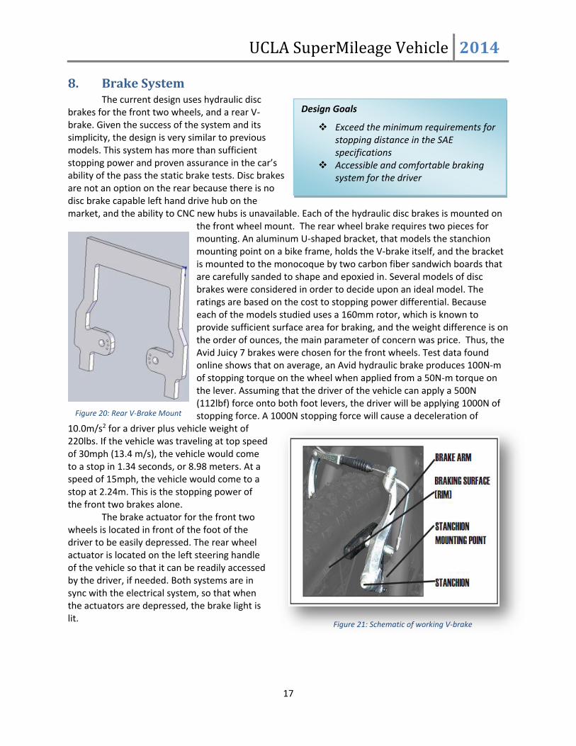
8. Brake System The current design uses hydraulic disc
brakes for the front two wheels, and a rear V-brake. Given the success of the system and its simplicity, the design is very similar to previous models. This system has more than sufficient stopping power and proven assurance in the car’s ability of the pass the static brake tests. Disc brakes are not an option on the rear because there is no disc brake capable left hand drive hub on the market, and the ability to CNC new hubs is unavailable. Each of the hydraulic disc brakes is mounted on
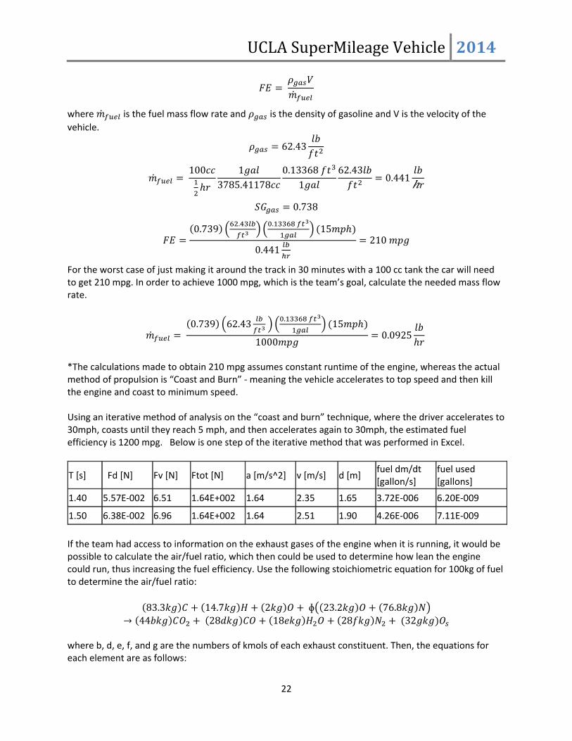
the front wheel mount. The rear wheel brake requires two pieces for mounting. An aluminum U-shaped bracket, that models the stanchion mounting point on a bike frame, holds the V-brake itself, and the bracket is mounted to the monocoque by two carbon fiber sandwich boards that are carefully sanded to shape and epoxied in. Several models of disc brakes were considered in order to decide upon an ideal model. The ratings are based on the cost to stopping power differential. Because each of the models studied uses a 160mm rotor, which is known to provide sufficient surface area for braking, and the weight difference is on the order of ounces, the main parameter of concern was price. Thus, the Avid Juicy 7 brakes were chosen for the front wheels. Test data found online shows that on average, an Avid hydraulic brake produces 100N-m of stopping torque on the wheel when applied from a 50N-m torque on the lever. Assuming that the driver of the vehicle can apply a 500N (112lbf) force onto both foot levers, the driver will be applying 1000N of stopping force. A 1000N stopping force will cause a deceleration of
10.0m/s2 for a driver plus vehicle weight of 220lbs. If the vehicle was traveling at top speed of 30mph (13.4 m/s), the vehicle would come to a stop in 1.34 seconds, or 8.98 meters. At a speed of 15mph, the vehicle would come to a stop at 2.24m. This is the stopping power of the front two brakes alone.
The brake actuator for the front two wheels is located in front of the foot of the driver to be easily depressed. The rear wheel actuator is located on the left steering handle of the vehicle so that it can be readily accessed by the driver, if needed. Both systems are in sync with the electrical system, so that when the actuators are depressed, the brake light is lit.
Figure 21: Schematic of working V-brake
Design Goals
Exceed the minimum requirements for stopping distance in the SAE specifications
Accessible and comfortable braking system for the driver
Figure 20: Rear V-Brake Mount

UCLA SuperMileage Vehicle 2014
18
9. Driver Safety and Comfort Features
Driver Safety Features Kill Switches There are three kill switches grounding the engine ignition as required by SAE Competition Rules. All of these kill switches shut off power to the engine and are positive action, toggle type toggle level arm (a.k.a. flip switches). One of these kill switches is within the vehicle itself in a position of easy accessibility for the driver on the steering levers. The other two are on the outside of the fairing accessible in any orientation to an outside person. Guards and Shields In order to protect the driver, certain safety measures must be made in order to separate the driver from moving parts of the vehicle or any other harmful elements. The driver is securely separated by a fire wall (see section “Fire Wall”) from any moving parts of the vehicle’s drive train compartment. The front wheels will be internal to the fairing and are separated from the driver by internal wheel covers composed of 1/16” polycarbonate. Polycarbonate was chosen because of its excellent clarity that does not impair driver vision, but also to protect the driver from the rotating wheels and possible debris from the road pavement. Other guards are placed within the vehicle to ensure further safety. For example, the aluminum chain guard protects any person working on the vehicle from the moving chain, as well as other components within the bulkhead. In addition, the battery terminals will be sufficiently insulated from the environment to avoid short circuits. Electrical wires are gathered in wiring harnesses and strapped down onto parts of the chassis in a way that prevents contact between the wiring and moving parts of the vehicle. Helmets/Clothing What the driver wears when driving the vehicle is vital to increasing his chances of remaining unharmed in the event of an unforeseen accident. During competition, the driver will wear a Harley-Davidson motorcycle helmet with an outer shell of fiberglass and polyester resin. This helmet is Snell M2000 approved as required by safety requirements. The helmet visor worn by the driver is made out of an impact resistant material. The driver will also wear a fire resistant racing jumpsuit from G-Force Racing. To further ensure the safety of the driver, the team strictly enforces that he/she wears durable shoes as well as gloves. Brake System There are two types of braking systems implemented: bicycle hydraulic disk brakes for the front two wheels and a v-brake for the rear engine driven wheel. The brake actuator for the front two wheels is located in front of the foot of the driver to be easily depressed. The rear wheel actuator is located on the steering of the vehicle so that it can be readily accessed by the driver if needed. For further information, see the Brake System section (8).
Design Goals:
Maintain driver safety as the top priority in all design choices
Incorporate active and passive elements of ensuring driver and team safety

UCLA SuperMileage Vehicle 2014
19
Fire Extinguisher A multipurpose fire ABC dry chemical extinguisher is mounted in such a way within the vehicle so that the driver should have sufficient amount of movement for activating the fire extinguisher. The fire extinguisher nozzle is connected to a simple hosing system within the engine compartment that points towards the fuel bottle and engine. These are locations that fires are most likely to arise. Exhaust System The engine exhaust exits the body of the vehicle through an exhaust pipe that extends to the outside from the side of the vehicle. To reduce the risk of burns, this exhaust pipe is properly insulated and is also sealed tight by gaskets. Firewall The firewall of the vehicle is fabricated out of a sheet of .032” thick aluminum metal that meets minimum thickness requirements. To prevent the risk of cuts, thick tape is used to cover the sharp edges of the fire wall. As laid out by the 2014 SAE Supermileage Rules, the firewall is extended slightly past the top of the driver’s helmet when worn with an overhead spacing of less than 0.5 inches in diameter between itself and the vehicle’s fairing/shell. Given the unique shape of the monocoque, the firewall will mount to the front of the rear part of the monocoque. Exitability One main concern is the ability and the quickness of the driver to escape from the vehicle in the event of an accident. Thus, all electrical wiring within the driver’s compartment is strapped down on sections of the monocoque in a way so as not to hinder the driver’s ability to exit the vehicle. Velcro securely fastens the top piece of the fairing to the bottom monocoque. This allows for easy removal, but also firm attachment during driving. The driver will be able to exit the vehicle within 15 seconds by himself. Two support personnel can also extract the driver within 20 seconds. These meet the requirements for excitability as indicated in the 2014 SAE Supermileage Rules. Visibility Performance and safety standards are greatly compromised if the driver does not have adequate visibility when driving the vehicle. The vehicle's windows are designed so that the driver's forward field of visibility is greater than +/- 80° from the vertical longitudinal axis. For the polycarbonate windows, the interior is treated with an anti-fogging agent and the exterior is treated with a water beading agent. Great care was taken to properly thermoform the windows. For more information on this, see Windows Section (4.4). Mirrors, securely mounted on the side of the vehicle, are adjustable for proper rearward (behind and to each side) visibility as required in the 2014 SAE Supermileage Rules. For visibility and safety reasons, the driver is positioned in the vehicle so that her feet are positioned forward towards the front of the vehicle. Roll bar / frame hoop Because the vehicle must be able to protect the driver in case it flips over, a roll protection device is critical. Therefore, the vehicle utilizes a roll hoop made from a carbon fiber sandwich structure with 1” aluminum flexcore. Similar to the fabrication of the monocoque, there are two plys of carbon fiber weave on each side of the flexcore. This roll hoop can withstand a 250 lb force applied to it. The roll hoop meets the measurement requirements of being at least the driver’s shoulder width, a minimum of 2 inches above the tallest driver’s helmet, and within 4 inches of being close to some portion of the driver’s helmet. See the Body Design Section (4) for more information.

UCLA SuperMileage Vehicle 2014
20
Driver Restraint In order to secure the driver safely in the vehicle, a 5-point driver safety harness that exceeds requirements as stated in the 2014 SAE Supermileage Rules is employed. The harness’ belt points are strong enough so that they can be used to lift the vehicle along with the driver. Headrest A headrest will be installed in the car in front of the firewall to support the driver’s head while the car is in use. The headrest will be made of Charcoal Regular Foam. The headrest will dampen vibrations caused by the engine or the bumps on the road pavement. Brake Light The rear brake light will be mounted to the rear of the fairing and will light up when starting the vehicle and during braking. The brake light will warn other vehicles to this vehicle's braking.
10. Performance Estimates
Performance: In order to evaluate the car’s performance, a force balance equation is performed to evaluate the acceleration of the car. With acceleration, an estimate of the vehicle’s fuel efficiency can be made. First, evaluate the acceleration by balancing of propulsive and resistive forces; propulsive force comes from the power transmitted from the engine to the wheels (Fp), resistive forces include drag force from air resistance (Fd), rolling friction from the wheels (Fr), and viscous friction from engine components (Fv). The equations describing each force are shown below.
𝐹𝑃 = 𝑇𝑤ℎ𝑒𝑒𝑙
𝑅 𝐹𝑑 =
1
2𝐶𝑑𝜌𝑉2𝐴𝑐
𝐹𝑟 = 𝑚𝑔𝐶𝑟 𝐹𝑣 = 𝐶𝑣𝑉
The propulsive force, Fp, is composed of the torque applied to the wheel divided by the radius of the wheel, R. The drag force is a function of a drag coefficient, Cd, the density of air, ρ, the velocity of the vehicle, V, and the cross sectional area of the vehicle, Ac. The rolling resistance is the product of the vehicle’s mass, m, gravity, g, and a coefficient of rolling resistance, Cr. The viscous friction is the product of the vehicles velocity and the viscosity coefficient, Cv. Evaluation of Propulsive Power:
𝑇𝑤ℎ𝑒𝑒𝑙 = 𝑇𝑒𝑛𝑔𝑖𝑛𝑒 ∗ 𝐺𝑅
(GR is the gear ratio) 6.27 [𝑁𝑚] ∗ 6.6 = 41.38 [𝑁𝑚]
𝐹𝑝 = 41.38 [𝑁𝑚]
0.2345 [𝑚]= 176.13 𝑁

UCLA SuperMileage Vehicle 2014
21
Evaluation of Drag Force: Cd = 0.09 (from SolidWorks’ fluid flow analysis)
𝜌 =𝑃
𝑅𝑇=
101325 𝑃𝑎
(287.05𝐽
𝑘𝑔𝐾) (300 𝐾)
= 1.77 𝑘𝑔
𝑚3
𝑉 = 17 𝑚𝑝ℎ = 7.60𝑚
𝑠
𝐴𝑐 = 0.343 𝑚2
𝐹𝑑 =1
2(0.09) (1.77
𝑘𝑔
𝑚3) (6.7056
𝑚
𝑠)
2
(0.343 𝑚2) = 1.030 𝑁
Evaluation of Rolling Resistance: Estimated Weight of Vehicle: 86 lbs Weight of driver: 130 lbs Estimated Total Weight: 216 lbs
𝑚 = 216 𝑙𝑏𝑠 = 97.98 𝑘𝑔 𝑔 = 9.81 𝑚/𝑠2
𝐶𝑟 = 0.0055
𝐹𝑟 = (104.33 𝑘𝑔) (9.81𝑚
𝑠2) (0.0055) = 5.286 𝑁
Evaluation of Viscous Forces
𝐶𝑣 = 2.77𝑁𝑠
𝑚
𝑉 = 15 𝑚𝑝ℎ = 6.7056𝑚
𝑠
𝐹𝑣 = (2.77𝑁𝑠
𝑚) (6.7056
𝑚
𝑠) = 18.575 𝑁
Force Balance
𝑚𝑎𝑥 = 𝐹𝑝 − 𝐹𝑑 − 𝐹𝑟 − 𝐹𝑣
𝑎𝑥 =176.13𝑁 − 1.030𝑁 − 5.286 𝑁 − 18.575𝑁
97.98𝑘𝑔= 1.544
𝑚
𝑠2
The estimated acceleration is 1.544 m/s2, which means to reach a top speed of 30 mph (13.4 m/s) it will take 8.68 seconds.
𝑣𝑓 − 𝑣𝑜 = 𝑎𝑥∆𝑡
13.4𝑚
𝑠− 0
𝑚
𝑠= (1.544 𝑚/𝑠2)∆𝑡
∆𝑡 =13.4
𝑚
𝑠
1.544𝑚
𝑠2
= 8.68 𝑠
With the theoretical acceleration, estimate the fuel efficiency (FE):
UCLA SuperMileage Vehicle 2014
22
𝐹𝐸 = 𝜌𝑔𝑎𝑠𝑉
�̇�𝑓𝑢𝑒𝑙
where �̇�𝑓𝑢𝑒𝑙 is the fuel mass flow rate and 𝜌𝑔𝑎𝑠 is the density of gasoline and V is the velocity of the
vehicle.
𝜌𝑔𝑎𝑠 = 62.43𝑙𝑏
𝑓𝑡2
�̇�𝑓𝑢𝑒𝑙 = 100𝑐𝑐
1
2ℎ𝑟
1𝑔𝑎𝑙
3785.41178𝑐𝑐
0.13368 𝑓𝑡3
1𝑔𝑎𝑙
62.43𝑙𝑏
𝑓𝑡2= 0.441
𝑙𝑏
ℎ𝑟
𝑆𝐺𝑔𝑎𝑠 = 0.738
𝐹𝐸 =(0.739) (
62.43𝑙𝑏
𝑓𝑡3 ) (0.13368 𝑓𝑡3
1𝑔𝑎𝑙) (15𝑚𝑝ℎ)
0.441𝑙𝑏
ℎ𝑟
= 210 𝑚𝑝𝑔
For the worst case of just making it around the track in 30 minutes with a 100 cc tank the car will need to get 210 mpg. In order to achieve 1000 mpg, which is the team’s goal, calculate the needed mass flow rate.
�̇�𝑓𝑢𝑒𝑙 = (0.739) (62.43
𝑙𝑏
𝑓𝑡3 ) (0.13368 𝑓𝑡3
1𝑔𝑎𝑙) (15𝑚𝑝ℎ)
1000𝑚𝑝𝑔= 0.0925
𝑙𝑏
ℎ𝑟
*The calculations made to obtain 210 mpg assumes constant runtime of the engine, whereas the actual method of propulsion is “Coast and Burn” - meaning the vehicle accelerates to top speed and then kill the engine and coast to minimum speed. Using an iterative method of analysis on the “coast and burn” technique, where the driver accelerates to 30mph, coasts until they reach 5 mph, and then accelerates again to 30mph, the estimated fuel efficiency is 1200 mpg. Below is one step of the iterative method that was performed in Excel.
T [s] Fd [N] Fv [N] Ftot [N] a [m/s^2] v [m/s] d [m] fuel dm/dt [gallon/s]
fuel used [gallons]
1.40 5.57E-002 6.51 1.64E+002 1.64 2.35 1.65 3.72E-006 6.20E-009
1.50 6.38E-002 6.96 1.64E+002 1.64 2.51 1.90 4.26E-006 7.11E-009
If the team had access to information on the exhaust gases of the engine when it is running, it would be possible to calculate the air/fuel ratio, which then could be used to determine how lean the engine could run, thus increasing the fuel efficiency. Use the following stoichiometric equation for 100kg of fuel to determine the air/fuel ratio:
(83.3𝑘𝑔)𝐶 + (14.7𝑘𝑔)𝐻 + (2𝑘𝑔)𝑂 + ɸ((23.2𝑘𝑔)𝑂 + (76.8𝑘𝑔)𝑁)
→ (44𝑏𝑘𝑔)𝐶𝑂2 + (28𝑑𝑘𝑔)𝐶𝑂 + (18𝑒𝑘𝑔)𝐻2𝑂 + (28𝑓𝑘𝑔)𝑁2 + (32𝑔𝑘𝑔)𝑂𝑠 where b, d, e, f, and g are the numbers of kmols of each exhaust constituent. Then, the equations for each element are as follows:

UCLA SuperMileage Vehicle 2014
23
H : 14.7 = 2e e = 7.35 N : 76.8ɸkkmol C : 83.3 = 12(b + d) O : 2 + 23.2 ɸ = 32b + 16d + 16e + 32g
Exhaust analysis could give the ratios of b/d and g/d, which could be used to solve for φ, the air/fuel ratio. Having this information would be used to modify the engine for a leaner air/fuel mixture, thus lowering the amount of gasoline used. Additionally, if the sensors were installed to determine the fuel flow rate, the thermal efficiency of the engine could be found. Sensors are currently being installed at the writing of this report for the EFI system. More detailed calculations of fuel consumption will be available in the next year’s report.
11. Cost Estimate and Manufacturing Methods
A detailed itemized cost estimate with material, tooling, and service estimates is found inAppendix C. The following is a description of the team’s manufacturing methods for the vehicle.
The vehicle body, steering, and powertrain were designed using the Student Edition version of SolidWorks CAD software. The software was donated to the team by the developers.
Though the female mold used for the body of the vehicle was reused from the 2013 model, it is still included in this report since the body was entirely redone and the body is the most labor-intensive element of the vehicle. The body female mold is shaped from a Styrofoam master male plug. Foam Sales and Marketing donated polystyrene Styrofoam. A projector borrowed from an UCLA library projected cross-sections of the vehicle onto 1 to 4 inch thick Styrofoam boards. The cross sections were cut according to the shape of the Solidworks model. The foam cross-sections were then glued together using spray on adhesive. The cross sections were then sanded down to achieve a smooth male plug. Then Bond-o was applied to all exposes surfaces of the foam. The Bond-o was also sanded down to shape for a smooth finish and to fill in gaps in the foam. To protect the foam from chemicals used during the female mold fabrication, StyroSafe was applied to all surfaces of the plug. Styrosafe is a laminating resin donated by RevChem.
After completion of the male plug, Performance Composites fabricated the female mold. They provided all raw materials, facilities, and expertise in the creation of the fiberglass female mold. The help provided is invaluable. All materials they provided would cost over a thousand dollars, let alone additional money for their expertise and labor. After the fiberglass female mold was created, the UCLA team began the vacuum lay-up process with our carbon-fiber and aluminum flexcore. Boeing donated the prepreg carbon fiber and Hysol. SpaceX donated the aluminum flexcore. General Sealants donated vacuum sealant tape, and Airtech donated vacuum bagging and peel-ply. After the lay-up process was completed, Performance Composites again assisted the team by curing the vehicle in their large oven, free of charge.
Figure 22: Foam Male Mold Fabrication

UCLA SuperMileage Vehicle 2014
24
The team also converted a Briggs and Stratton engine to OHV, using a new Briggs and Stratton 550 OHV head. A new adaptor plate was made to match the bolt patterns of the crankcase and head. After machining the adaptor plate with the UCLA waterjet and in the UCLA Student Machine Shop, the plate and stock engine block was taken to LA Sleeve. LA Sleeve milled off the appropriate amount from the stock engine block, attached the adaptor plate, and resleeved the engine. LA Sleeve performed this service free of charge.
To further improve engine efficiency, an EFI system was developed by the team. Several components were used from an EFI kit purchased at a reduced price from Ecotrons. Additional wiring, soldering station, replacement sensors, Sainsmart Mega 2560 controller, and new battery were purchased for the completion of this system. In addition, to analyze the signals from the sensors, the team acquired a new oscilloscope, donated by Schneider Electric.
The majority of aluminum components, including wheel mounts, firewall, and steering assembly, came from donated scrap metal from Kaiser Aluminum. Additional metal was also purchased for the steering levers. Metal components were machined and welded in the UCLA Student Machine Shop under the guidance of shop supervisors Michael O’Leary, Anatoly Mathus, and Miguel Lozano.
The most extravagant expenditures this year will be with regard to traveling. To travel to the Shell Eco-Marathon Americas in Houston, TX will cost about $2500. These costs are for gas and rentals for a large van and trailer. Costs to attend SAE SuperMileage in Marshall, MI, will be even more extravagant, ranging up to $3000 dollars for vehicle freight and team members’ airfare. In an attempt to create a safer and timelier journey to and from Michigan, the vehicle will ship via freight and team members will fly on a commercial airline.
Table 1: Cost Estimate Summary
The total cost of the vehicle (without travel) has a nominal cost of $15,830. This cost includes all materials, tooling, and estimated labor costs. However, through industry and sponsorship, the UCLA team reduced this amount to only $1,930. An additional $5,500 is needed for travel expenditures to the Shell Eco Marathon Americas and SAE Supermileage Competition. A detailed cost estimate is shown in Appendix C.


UCLA SuperMileage Vehicle 2014
26
Appendix
A. Electric Fuel Injection Components
1. Sainsmart Mega 2560 (Microcontroller) 2. 16x2 Character LCD Display 3. Voltage Regulators (12V to 9V and 12V to 5V) 4. Harness (including the connectors) 5. Throttle Body 28mm 6. TPS (Throttle Position Sensor) 7. Fuel injector 8. Fuel pump (38mm diameter) (2A current) (Flow rate: 25L/h) 9. Fuel pressure regulator (2.5bar) 10. Fuel filter 11. Fuel hoses and clamps 12. MAP (Mass Absolute Pressure) sensor (1.05bar) 13. ECT Sensor (Engine Temperature Sensor) 14. IAT Sensor (Intake Air Temperature sensor) 15. Oxygen sensor 16. Hall Effect Sensor

UCLA SuperMileage Vehicle 2014
27
B. Engine Control Circuit Diagram

UCLA SuperMileage Vehicle 2014
28
C. Itemized Cost Estimate
Item
Nominal
Cost
Amount
Paid by
Team DonorMATERIALS &
TOOLING
SolidWorks CAD $5,000 $0 SolidWorks
Vehicle Body &
Structures
Prepreg carbon
fiber weave $2,000 $0 Boeing
Flexcore $1,000 $0 SpaceX
Hysol $200 $0 Boeing
Male Plug
Polyester
styrofoam
boards $200 $0 Foam Sales and Marketing
Bondo $200 $200 Purchased
Styrosafe resin $100 $0 RevChem
Female mold $1,000 $0 Performance Composites
Vacuum sealant
tape $200 $0 General Sealants
Vacuum bag and
peel-ply $200 $0 Airtech
Gelcoat painting $100 $100 Purchased
Paint thinner and
cleaning agents $40 $40 Purchased
Polycarbonate for
windows $80 $80 Purchased
Epoxy Resin $80 $80 Purchased
Powertrain
New OHV head $90 $90 Purchased
Adaptor plate $60 $60 Purchased
New cylinder
sleeve $100 $0 LA Sleeve
EFI system $330 $330 Discounted by Ecotrons
New sensors,
wiring, Arduino,
battery $250 $250 Purchased
Aluminum plates,
rods, tubing $320 $20 Kaiser Aluminum
Wheels
Custom wheels $300 $300 Discounted by Wheelbuilders
Tires $250 $250 Purchased
Inner tubes $50 $50 Purchased
Miscellaneous
Electrical
components &
wiring $40 $40 Purchased
Oscilloscope $600 $0 Schneider Electric
Fasteners $40 $40 Purchased
SUBTOTAL $12,830 $1,930

UCLA SuperMileage Vehicle 2014
29
ESTIMATED LABOR
COST
Female mold
fabrication $2,000 $0 Performance Composites
Vehicle oven curing $500 $0 Performance Composites
OHV Modification $500 $0 LA Sleeve
SUBTOTAL $3,000 $0
TRAVEL
EXPENDITURES
Shell Eco Marathon
Americas $2,500 $2,500 Purchased
SAE Supermileage $3,000 $3,000 Purchased
SUBTOTAL $5,500 $5,500