U3800 Series User's Guide
480
MANUAL NUMBER C Printed in Japan ADVANTEST CORPORATION All rights reserved. U3800 Series User’s Guide FOE-8440285E00 First printing April 30, 2011 Applicable Models U3841 U3851 U3872 2011 Cover
Transcript of U3800 Series User's Guide

MANUAL NUMBER
CPrinted in Japan
ADVANTEST CORPORATIONAll rights reserved.
U3800 Series
User’s Guide
FOE-8440285E00
First printing April 30, 2011
Applicable ModelsU3841U3851U3872
2011
Cover


No. CSA_A00
S-1
This product has been tested to the requirements of CAN/CSA-C22.2 No. 61010-1, second edition,including Amendment 1, or a later version of the same standard incorporating the same level oftesting requirements.
CSA

Certificate of Conformity
This is to certify, that
complies with the provisions of the EMC Directive 2004/108/EC in accordance with
EN61326 and Low Voltage Directive 2006/95/EC in accordance with EN61010.
ADVANTEST Corp. ROHDE&SCHWARZTokyo, Japan International Operations
GmbHMunich, Germany
instrument, type, designation
U3800.00
Cross Domain Analyzer
U3800 Series
Certificate of Conformity


No. KC Class B_A00
K-1
KC Class B
• Applicant: ADVANTEST corporation
• Registration No.: KCC-REM-qa2-U3872
• Equipment Name: Cross Domain Analyzer
• Basic Model Number: U3841/U3851/U3872
• Manufacturer: ADVANTEST corporation
• Country of Origin: Japan
• Year and month of manufacture: Refer to the product label
KC Class B


U3800 Series User's Guide
CR-1
有毒有害物质含量信息说明书• 本有毒有害含量含量说明内容是为了贯彻 [ 电子信息产品污染控制管理办法 ] 而
编制的。This document is made for Chinese Administration on the Control of Pollution Caused by ElectronicInformation Products, unofficially called "China-RoHS".この文書は、中国の「電子情報製品汚染防止管理弁法」のための文書です。
1. 产品中贴有电子信息产品污染控制标志及产品中有毒有害物质或元素的名称及含量
2. 环保使用期限内的使用条件
适用机种 U3841, U3851, U3872
电子信息产品污染控制标志
部件名称
有毒有害物质或元素
铅(Pb)
汞(Hg)
镉(Cd)
六价铬(Cr(VI))
多溴联苯(PBB)
多溴二苯醚(PBDE)
Main frame
Boards
Power supply parts
Cable
LCD Panel
Module
Parts
CD-ROM
: 表示该有毒有害物质在该部件所有均质材料中的含量均在 SJ/T11363-2006 规定的限量要求以下。
: 表示该有毒有害物质至少在该部件的某一均质材料中的含量超出 SJ/T11363-2006 规定的限量要求。(企业可在此处,根据实际情况对上表中打 的技术原因进行进一步说明。)
本表对此次发送产品中所有部件中有毒有害物质的含量,全部作了注明。另外,也有可能包含了与本次发送的产品无关的部件的相关信息。
运作环境温度范围 +0C ~ +50C
相对湿度 在 85% 以下 (但是,不得结霜)
设置环境温度范围 -20C ~ +60C
相对湿度 在 85% 以下 (但是,不得结霜)
周围环境
不会产生腐蚀性气体的地方不是直射阳关的地方灰尘少的地方没有震动的地方
Hazardous Substances Component Information Manual


U3800 Series User's Guide
Preface-1
Preface1. Structure of this Manual
This manual can be used by novices or experienced users of this instrument. You may read through this man-ual from Chapter 1 to learn more about this instrument or you may refer to the table of contents, which isfound at the beginning of each chapter and directly jump to the section that you need.
The contents of each chapter are as follows:
2. Trademarks
• ADVANTEST is a trademark of Advantest Corporation.
• Visual Basic 6.0 and Visual Basic 2008 are trademarks or registered trademarks of Microsoft Corpora-tion in the United States and other countries.
• K Connector is a trademark of Anritsu Corporation.
• All other product names described in this manual are the trademarks of their respective owners.
Chapter 1. Introduction This chapter describes the contents of this manual and the product overview.
Chapter 2. Precautions When Using the U3800 This chapter describes precautions when using this instru-ment. Read this chapter before using this instrument.
Chapter 3. Setup This chapter describes how to setup this instrument. After setting up this instrument in an appropriate location, turn on the power and check that this instrument starts correctly.
Chapter 4. Instrument Configuration and Basic Operations
This chapter describes the functions of each part of the panel and the screen of this instrument. You can learn how to operate this instrument from the operations and simple examples.
Chapter 5. Menu Map and Function Description This chapter describes the menu structure and functions of soft keys.
Chapter 6. Overview of Remote Control This chapter describes how to connect and set the GPIB and LAN interfaces, and also describes the program exam-ples used when programming and table of commands.
Chapter 7. Specifications This chapter describes the specifications of this instrument.
Chapter 8. Options and Accessories This chapter describes options and accessories which are sold separately.
Chapter 9. Maintenance This chapter describes how to care for this instrument such as cleaning, calibration, and storage to maintain the high performance and smooth functioning of this instrument. Also this chapter describes how to identify problems and the relevant procedures to follow.
Preface


U3800 Series User’s Guide
C-1
Table of Contents
1. Introduction .................................................................................................... 1-1
1.1 Product Overview .............................................................................................. 1-11.2 Conventions of Notation Used in This Document ............................................ 1-11.3 Advantest Homepage ........................................................................................ 1-1
2. Precautions When Using the U3800 ........................................................ 2-1
2.1 If a Fault Occurs ................................................................................................ 2-12.2 Removing the Case ........................................................................................... 2-12.3 Electromagnetic Interference ............................................................................ 2-12.4 Prevention of Electrostatic Buildup .................................................................. 2-22.5 Note when Turning on the Power ..................................................................... 2-3
3. Setup ................................................................................................................ 3-1
3.1 Inspection on Delivery ...................................................................................... 3-13.2 Locating This Instrument .................................................................................. 3-33.2.1 Operating Environment .............................................................................. 3-33.3 Power Requirements ......................................................................................... 3-53.3.1 Connecting the Power Cable ...................................................................... 3-53.3.2 Power Fuse ................................................................................................. 3-63.4 Caution when Connecting Peripherals .............................................................. 3-73.5 Checking Operations ......................................................................................... 3-8
4. Instrument Configuration and Basic Operations .................................. 4-1
4.1 Panel and Screen Descriptions .......................................................................... 4-14.1.1 Names and Functions of Each Part on the Front Panel .............................. 4-14.1.1.1 Extended Function Key Block .................................................................... 4-24.1.1.2 Soft Key Block ........................................................................................... 4-34.1.1.3 Input and Output Connectors Block ........................................................... 4-44.1.1.4 Operation Key Block .................................................................................. 4-54.1.2 Names and Functions of Each Part on the Screen ...................................... 4-74.1.2.1 Spectrum Measurement .............................................................................. 4-74.1.2.2 Time Domain Measurement ....................................................................... 4-94.1.3 Names and Functions of Each Part on the Rear Panel ............................... 4-114.2 Basic Operation ................................................................................................. 4-124.2.1 Menu Operation and Data Entry ................................................................. 4-124.3 Basic Measurement ........................................................................................... 4-154.3.1 Level Calibration ........................................................................................ 4-164.3.2 Selecting the Active Channel (Window) .................................................... 4-194.3.3 Setting the Operation Mode and Display Mode ......................................... 4-204.3.4 Displaying Trace Status .............................................................................. 4-224.3.5 Measurement of Signals in Asynchronous Mode ....................................... 4-234.3.6 How to Cancel the UNCAL Message ........................................................ 4-274.3.7 Identifying an Image Signal ....................................................................... 4-294.3.8 Save/Recall ................................................................................................. 4-31
Table of Contents
U3800 Series User’s Guide
Table of Contents
C-2
4.3.9 COPY (File Output to USB Memory) ........................................................ 4-344.3.10 USER Key .................................................................................................. 4-354.3.11 Time Domain Analysis ............................................................................... 4-364.3.12 Synchronous Mode and Vector Calculation Function ................................ 4-424.3.13 Inter-channel Vector Correction ................................................................. 4-454.3.13.1 Correction Using Built-in Signal Source .................................................... 4-454.3.13.2 Correction Using External Signal Sources ................................................. 4-484.4 Measurement Example ...................................................................................... 4-494.4.1 Measurement of Power Ratio/Phase Difference between Channels .......... 4-494.4.2 Measurement Example with Vector Calculation Function ........................ 4-524.4.3 Cross Polarization Discrimination (XPD) Measurement ........................... 4-554.4.3.1 Using X Math Channel Power Ratio Measurement Function .................... 4-564.4.3.2 Using Trace Calculation Function .............................................................. 4-57
5. Menu Map and Function Description ..................................................... 5-1
5.1 Menu Index ....................................................................................................... 5-15.2 Function Description ......................................................................................... 5-85.2.1 SELECT ..................................................................................................... 5-85.2.2 SYNC ......................................................................................................... 5-85.2.3 LOCAL REMOTE ..................................................................................... 5-85.2.4 SYSTEM .................................................................................................... 5-95.2.4.1 Mode ........................................................................................................... 5-105.2.4.2 Calibration .................................................................................................. 5-135.2.4.3 Config ......................................................................................................... 5-155.2.4.4 File .............................................................................................................. 5-225.2.4.5 TG ............................................................................................................... 5-345.2.4.6 Version ....................................................................................................... 5-365.2.4.7 Setup copy .................................................................................................. 5-375.2.4.8 Title ............................................................................................................. 5-395.2.4.9 Self Test ...................................................................................................... 5-405.2.4.10 Factory Init ................................................................................................. 5-405.2.5 PRESET ...................................................................................................... 5-405.2.6 APPLI ......................................................................................................... 5-415.2.6.1 EMC ........................................................................................................... 5-415.2.7 DISP ........................................................................................................... 5-505.2.7.1 Screen ......................................................................................................... 5-515.2.7.2 Measuring Window .................................................................................... 5-525.2.7.3 Limit Lines ................................................................................................. 5-535.2.7.4 Ref / Disp Lines .......................................................................................... 5-575.2.7.5 Zoom and Contexts ..................................................................................... 5-585.2.7.6 Screen ......................................................................................................... 5-615.2.7.7 Limit Lines ................................................................................................. 5-625.2.7.8 Ref / Disp Lines .......................................................................................... 5-655.2.7.9 Position View ............................................................................................. 5-665.2.7.10 Dual Measure .............................................................................................. 5-675.2.8 RECALL ..................................................................................................... 5-695.2.9 SAVE .......................................................................................................... 5-695.2.10 COPY ......................................................................................................... 5-695.2.11 HELP .......................................................................................................... 5-695.2.12 SHIFT ......................................................................................................... 5-70

U3800 Series User’s Guide
Table of Contents
C-3
5.2.13 Xmath ......................................................................................................... 5-705.2.13.1 Power Ratio Phase Diff .............................................................................. 5-715.2.13.2 Differential ................................................................................................. 5-735.2.13.3 Ch Power Diff ............................................................................................. 5-755.2.13.4 Math ............................................................................................................ 5-765.2.13.5 Correction Data Info ................................................................................... 5-795.2.13.6 Xmath OFF ................................................................................................. 5-805.2.14 MEAS 1 ...................................................................................................... 5-815.2.14.1 Spectrum Analysis ...................................................................................... 5-815.2.14.2 Freq - Time ................................................................................................. 5-815.2.14.3 Phase - Time ............................................................................................... 5-815.2.14.4 Power - Time .............................................................................................. 5-825.2.14.5 IQ - Time .................................................................................................... 5-825.2.14.6 Power - Freq ............................................................................................... 5-825.2.15 MEAS 2 ...................................................................................................... 5-835.2.15.1 TX Meas ..................................................................................................... 5-845.2.15.2 MKR Meas ................................................................................................. 5-1045.2.15.3 Pulse Meas .................................................................................................. 5-1115.2.15.4 AM/FM Meas ............................................................................................. 5-1135.2.16 TRACE ....................................................................................................... 5-1165.2.16.1 Trace A ....................................................................................................... 5-1165.2.16.2 Trace B ....................................................................................................... 5-1215.2.16.3 Trace C ....................................................................................................... 5-1215.2.16.4 Trace Math In Ch ........................................................................................ 5-1225.2.16.5 Trace Math Cross Ch .................................................................................. 5-1235.2.16.6 Store ............................................................................................................ 5-1245.2.17 MKR ........................................................................................................... 5-1255.2.17.1 Select Marker .............................................................................................. 5-1255.2.17.2 Marker ON|OFF ......................................................................................... 5-1265.2.17.3 Marker Trace A|B|C|M|O ........................................................................... 5-1265.2.17.4 Delta Mode ................................................................................................. 5-1265.2.17.5 Search Menu ............................................................................................... 5-1275.2.17.6 Clear All ..................................................................................................... 5-1345.2.17.7 Others HIDE|SHOW .................................................................................. 5-1355.2.17.8 Clear Others ................................................................................................ 5-1355.2.17.9 Display List ON|OFF .................................................................................. 5-1355.2.17.10 Mkr Step AUTO|MNL ............................................................................... 5-1355.2.17.11 Mode Index|Value ...................................................................................... 5-1365.2.17.12 Clear All ..................................................................................................... 5-1365.2.17.13 Signal Track ................................................................................................ 5-1365.2.18 PEAK .......................................................................................................... 5-1375.2.19 MKR 5.2.19.1 Mkr to CF ................................................................................................... 5-1385.2.19.2 Mkr to Ref .................................................................................................. 5-1385.2.19.3 Peak to CF .................................................................................................. 5-1385.2.19.4 Peak to Ref ................................................................................................. 5-1385.2.19.5 Delta to Zoom ............................................................................................. 5-1395.2.19.6 Delta to CF ................................................................................................. 5-1395.2.19.7 Mkr to CF Step ........................................................................................... 5-1395.2.19.8 Delta to CF Step ......................................................................................... 5-1395.2.19.9 Mkr to Mkr Step ......................................................................................... 5-140

U3800 Series User’s Guide
Table of Contents
C-4
5.2.19.10 Delta to Mkr Step ....................................................................................... 5-1405.2.19.11 Mkr to Alternate CF ................................................................................... 5-1405.2.19.12 Peak to Alternate CF .................................................................................. 5-1405.2.19.13 Delta to Alternate Zoom ............................................................................. 5-1415.2.19.14 Mkr to CF ................................................................................................... 5-1415.2.19.15 Mkr to Analysis Ofs ................................................................................... 5-1415.2.19.16 Delta to Zoom ............................................................................................. 5-1415.2.19.17 Mkr to Vertical Pos .................................................................................... 5-1425.2.19.18 Delta to V Scale/div .................................................................................... 5-1425.2.19.19 Mkr to Mkr Step ......................................................................................... 5-1425.2.19.20 Delta to Alternate Zoom ............................................................................. 5-1435.2.19.21 Mkr to Alternate CF ................................................................................... 5-1435.2.20 CURSOR .................................................................................................... 5-1435.2.20.1 Execute ON|OFF ........................................................................................ 5-1445.2.20.2 Mode SGL|DUAL ...................................................................................... 5-1445.2.20.3 Select A|B ................................................................................................... 5-1445.2.21 FREQUENCY ............................................................................................ 5-1455.2.21.1 Center ......................................................................................................... 5-1455.2.21.2 Start ............................................................................................................. 5-1455.2.21.3 Stop ............................................................................................................. 5-1465.2.21.4 Frequency Offset ON|OFF ......................................................................... 5-1465.2.21.5 CF Step Size AUTO|MNL ......................................................................... 5-1465.2.21.6 Channel Input ............................................................................................. 5-1475.2.21.7 Signal Identification ON|OFF .................................................................... 5-1505.2.21.8 Image Suppression ON|OFF ....................................................................... 5-1505.2.22 SPAN .......................................................................................................... 5-1515.2.22.1 Span ............................................................................................................ 5-1515.2.22.2 Full Span ..................................................................................................... 5-1515.2.22.3 Zero Span .................................................................................................... 5-1515.2.22.4 Last Span .................................................................................................... 5-1525.2.22.5 Peak Zoom .................................................................................................. 5-1525.2.22.6 Auto Tune ON|OFF .................................................................................... 5-1525.2.22.7 Analysis Offset ........................................................................................... 5-1535.2.22.8 Analysis Window ....................................................................................... 5-1535.2.23 AMPLITUDE ............................................................................................. 5-1545.2.23.1 Ref Level .................................................................................................... 5-1545.2.23.2 ATT ............................................................................................................ 5-1545.2.23.3 dB/div ......................................................................................................... 5-1555.2.23.4 Vertical Scale LIN|LOG ............................................................................. 5-1565.2.23.5 Units ........................................................................................................... 5-1565.2.23.6 Slide Screen ON|OFF ................................................................................. 5-1575.2.23.7 Ref Offset ON|OFF .................................................................................... 5-1575.2.23.8 Input Impedance 50|75 ............................................................................... 5-1575.2.23.9 High Sensitivity ON|OFF ........................................................................... 5-1585.2.23.10 Correction Factor ON|OFF ......................................................................... 5-1585.2.23.11 Edit Corr Factor .......................................................................................... 5-1585.2.23.12 Round Grid Values ON|OFF ...................................................................... 5-1595.2.23.13 Ref Level .................................................................................................... 5-1595.2.23.14 ATT ............................................................................................................ 5-1605.2.23.15 Vertical Scale/div ....................................................................................... 5-1605.2.23.16 Vertical Scale LIN|LOG ............................................................................. 5-161

U3800 Series User’s Guide
Table of Contents
C-5
5.2.23.17 Units ........................................................................................................... 5-1615.2.23.18 Vertical Position ......................................................................................... 5-1625.2.23.19 Ref Offset ON|OFF .................................................................................... 5-1625.2.23.20 Input Impedance 50|75 ............................................................................... 5-1625.2.23.21 High Sensitivity ON|OFF ........................................................................... 5-1635.2.23.22 Correction Factor ON|OFF ......................................................................... 5-1635.2.23.23 Edit Corr Fact ............................................................................................. 5-1645.2.24 SWEEP ....................................................................................................... 5-1655.2.24.1 Sweep Time AUTO|MNL .......................................................................... 5-1655.2.24.2 Sweep Mode SGL|CNT .............................................................................. 5-1655.2.24.3 Trigger ........................................................................................................ 5-1665.2.24.4 Gated Sweep ............................................................................................... 5-1675.2.24.5 Capture Time .............................................................................................. 5-1695.2.24.6 Sweep Mode SGL|CNT .............................................................................. 5-1695.2.24.7 Trigger ........................................................................................................ 5-1705.2.25 BW .............................................................................................................. 5-1725.2.25.1 RBW AUTO|MNL ..................................................................................... 5-1725.2.25.2 VBW AUTO|MNL ..................................................................................... 5-1725.2.25.3 EMC ........................................................................................................... 5-1735.2.25.4 All Auto ...................................................................................................... 5-1745.2.25.5 SPAN/RBW ON|OFF ................................................................................. 5-1745.2.25.6 VBW/RBW ON|OFF .................................................................................. 5-1745.2.25.7 Capture BW ................................................................................................ 5-1755.2.25.8 RBW AUTO|MNL ..................................................................................... 5-176
6. Overview of Remote Control .................................................................... 6-1
6.1 Remote Control ................................................................................................. 6-16.1.1 Types of Systems ........................................................................................ 6-16.2 GPIB Remote Control System .......................................................................... 6-26.2.1 What is the GPIB? ...................................................................................... 6-26.2.2 Setting up the GPIB .................................................................................... 6-36.2.3 GPIB Bus Functions ................................................................................... 6-46.2.3.1 GPIB Interface Functions ........................................................................... 6-46.2.3.2 Responses to Interface Messages ............................................................... 6-46.3 LAN Remote Control System ........................................................................... 6-66.3.1 Setting up the LAN ..................................................................................... 6-66.3.2 Setting the IP Address ................................................................................ 6-86.3.3 Control from a Controller ........................................................................... 6-96.4 Message Exchanging Protocol .......................................................................... 6-106.4.1 Buffers ........................................................................................................ 6-106.4.2 Message Exchange ..................................................................................... 6-106.5 Command Syntax .............................................................................................. 6-116.5.1 Command Syntax ....................................................................................... 6-116.5.2 Data Formats .............................................................................................. 6-126.5.3 Status Byte .................................................................................................. 6-136.6 GPIB Remote Programming ............................................................................. 6-206.7 AT Command Index .......................................................................................... 6-206.8 Operation of TS Command upon Dual CH ....................................................... 6-276.8.1 Operation .................................................................................................... 6-27

U3800 Series User’s Guide
Table of Contents
C-6
6.9 AT Command List ............................................................................................. 6-296.9.1 Mode ........................................................................................................... 6-296.9.2 Power Ratio Phase Diff .............................................................................. 6-306.9.3 Differential ................................................................................................. 6-316.9.4 Math ............................................................................................................ 6-326.9.5 Ch Power Diff ............................................................................................. 6-356.9.6 Frequency ................................................................................................... 6-356.9.7 Level ........................................................................................................... 6-376.9.8 Bandwidth ................................................................................................... 6-386.9.9 Sweep ......................................................................................................... 6-386.9.10 Trigger ........................................................................................................ 6-406.9.11 Trace ........................................................................................................... 6-416.9.12 Trace Math .................................................................................................. 6-446.9.13 Pass/Fail ...................................................................................................... 6-466.9.14 Display ........................................................................................................ 6-476.9.15 Marker ........................................................................................................ 6-496.9.16 Peak and Marker Move .............................................................................. 6-516.9.17 Peak ............................................................................................................ 6-526.9.18 Measurement .............................................................................................. 6-536.9.19 Counter ....................................................................................................... 6-566.9.20 Power .......................................................................................................... 6-566.9.21 EMC ........................................................................................................... 6-616.9.22 Calibration .................................................................................................. 6-626.9.23 Save/Recall ................................................................................................. 6-636.9.24 File Management ........................................................................................ 6-646.9.25 Vertical Cursor ........................................................................................... 6-656.9.26 Time Domain Analysis ............................................................................... 6-656.9.27 Config ......................................................................................................... 6-676.9.28 Preset .......................................................................................................... 6-676.9.29 GPIB ........................................................................................................... 6-686.9.30 Others ......................................................................................................... 6-696.9.31 TG ............................................................................................................... 6-716.9.32 Units ........................................................................................................... 6-726.10 I/Q Data Output ................................................................................................. 6-736.10.1 IQB Data Output ......................................................................................... 6-736.10.2 IQBSV Data Output ................................................................................... 6-746.11 Recalculation Operation Setting of Time Domain Analysis Using RECALCON 6-756.12 UNCAL Message, List of Error Messages, and Restrictions ............................ 6-756.12.1 How to Delete UNCAL Message for Partial FFT Analysis ....................... 6-756.13 Multiple-Points Correction Using External Signal Sources .............................. 6-766.13.1 Remote Commands for Specific Span ........................................................ 6-776.13.2 Remote Commands for InBand .................................................................. 6-786.14 Example Remote Control Program ................................................................... 6-796.14.1 Basic Steps for GPIB Bus Control ............................................................. 6-796.14.1.1 Reading GPIB Control Library .................................................................. 6-796.14.1.2 Example Programs ...................................................................................... 6-806.14.1.3 Sample Programs for Reading Data ........................................................... 6-896.14.1.4 Sample Programs for Inputting or Outputting Trace Data ......................... 6-1056.14.1.5 Example Program for Screen Image Output .............................................. 6-1216.14.1.6 Example Program Which Uses the TS (Take Sweep) Command .............. 6-123
U3800 Series User’s Guide
Table of Contents
C-7
6.14.1.7 Example Programs Which Use the Status Byte ......................................... 6-1266.14.1.8 Program Examples Using the LAN ............................................................ 6-1306.14.2 Example Program for Correcting Multiple Points Using External Signal
Source ......................................................................................................... 6-145
7. Specifications ................................................................................................ 7-1
7.1 U3841 Performance Specifications ................................................................... 7-27.1.1 Frequency ................................................................................................... 7-27.1.2 Sweep ......................................................................................................... 7-27.1.3 Amplitude ................................................................................................... 7-37.1.4 Amplitude Accuracy ................................................................................... 7-37.1.5 Dynamic Range .......................................................................................... 7-47.1.6 Vector Analysis .......................................................................................... 7-47.1.7 Input and Output ......................................................................................... 7-57.2 U3851 Performance Specifications ................................................................... 7-67.2.1 Frequency ................................................................................................... 7-67.2.2 Sweep ......................................................................................................... 7-67.2.3 Amplitude ................................................................................................... 7-77.2.4 Amplitude Accuracy ................................................................................... 7-77.2.5 Dynamic Range .......................................................................................... 7-87.2.6 Vector Analysis .......................................................................................... 7-87.2.7 Input and Output ......................................................................................... 7-97.3 U3872 Performance Specifications ................................................................... 7-107.3.1 Frequency ................................................................................................... 7-107.3.2 Sweep ......................................................................................................... 7-107.3.3 Amplitude ................................................................................................... 7-117.3.4 Amplitude Accuracy ................................................................................... 7-117.3.5 Dynamic Range .......................................................................................... 7-127.3.6 Vector Analysis .......................................................................................... 7-127.3.7 Input and Output ......................................................................................... 7-137.4 General Specifications ...................................................................................... 7-147.5 Options .............................................................................................................. 7-157.5.1 Option 20 High Stability Frequency Reference ......................................... 7-157.5.2 Option 28 EMC Filter ................................................................................. 7-157.5.3 Option 76 3 GHz Tracking Generator ........................................................ 7-157.5.4 Option 77 6 GHz Tracking Generator ........................................................ 7-16
8. Options and Accessories ............................................................................. 8-1
8.1 Options .............................................................................................................. 8-18.2 Accessories ........................................................................................................ 8-1
9. Maintenance ................................................................................................... 9-1
9.1 Cleaning ............................................................................................................ 9-19.1.1 Cabinet Cleaning ........................................................................................ 9-19.1.2 Cleaning of Other Parts .............................................................................. 9-29.2 About Calibration .............................................................................................. 9-29.3 About Replacement of Limited-Life Parts ........................................................ 9-2

U3800 Series User’s Guide
Table of Contents
C-8
9.4 Method of Storing the Instrument ..................................................................... 9-39.5 Transportation ................................................................................................... 9-39.6 Notes for Requesting Repair, Replacement of Parts, and Periodic Calibration 9-39.6.1 Work Request ............................................................................................. 9-39.6.2 Destination and Phone Number for Contact ............................................... 9-39.7 List of Error Messages ...................................................................................... 9-49.8 In Case of Difficulty .......................................................................................... 9-99.9 Product Disposal and Recycle ........................................................................... 9-10
U3841/U3851 Dimensional Outline Drawing.................................................... EXT-1
U3872 Dimensional Outline Drawing.................................................................. EXT-2
Alphabetical Index..................................................................................................... I-1

F-1
U3800 Series User’s Guide
List of Illustrations
No. Title Page
2-1 Countermeasures for Static Electricity of Human Bodies ................................................ 2-22-2 Countermeasures for Static Electricity of Work Site Floor .............................................. 2-22-3 Countermeasures for Static Electricity of Work Bench .................................................... 2-3
3-1 Operating Environment ..................................................................................................... 3-43-2 Connecting the Power Cable ............................................................................................. 3-53-3 Replacing Power Fuse ...................................................................................................... 3-63-4 Attachment of a Ferrite Core 1 ......................................................................................... 3-73-5 Attachment of a Ferrite Core 2 ......................................................................................... 3-73-6 POWER Switch ................................................................................................................ 3-83-7 Initial Screen ..................................................................................................................... 3-83-8 Connecting the CAL Signal .............................................................................................. 3-9
4-1 Front Panel ........................................................................................................................ 4-14-2 Extended Function Key Block .......................................................................................... 4-24-3 Soft Key Block .................................................................................................................. 4-34-4 Input and Output Connectors Block ................................................................................. 4-44-5 Operation Key Block ........................................................................................................ 4-54-6 Screen Display .................................................................................................................. 4-74-7 Freq-Time and Phase-Time Screens ................................................................................. 4-94-8 Power-Time and IQ-Time Screens ................................................................................... 4-94-9 Rear Panel ......................................................................................................................... 4-114-10 Connecting CAL Signal .................................................................................................... 4-174-11 Connecting CAL Signal (CH1 H-INPUT Connector) ...................................................... 4-184-12 Asynchronous Mode Signal Measurement Connection .................................................... 4-234-13 Asynchronous Mode Signal Measurement Screen ........................................................... 4-254-14 Frequencies and Levels in Cursor Positions ..................................................................... 4-264-15 UNCAL Message Displayed Screen ................................................................................. 4-274-16 UNCAL Message Deleted Screen .................................................................................... 4-284-17 Operation Example of Image Suppression ....................................................................... 4-294-18 Operation Example of Signal Identification ..................................................................... 4-304-19 Media Selection Dialog Box ............................................................................................. 4-314-20 USB Memory Selection Dialog Box ................................................................................ 4-344-21 Time Domain Analysis Connection .................................................................................. 4-364-22 Freq-Time Analysis Screen .............................................................................................. 4-394-23 Phase-Time Analysis Screen ............................................................................................ 4-394-24 Power-Time Analysis Screen ............................................................................................ 4-404-25 Power-Freq Analysis Screen ............................................................................................. 4-414-26 IQ-Time Analysis Screen .................................................................................................. 4-424-27 Inter-Channel Vector Calculation Dialog Box ................................................................. 4-434-28 Image for Differential Signal Vector Addition/Subtraction ............................................. 4-434-29 Inter-Channel Vector Calculation Analysis Screen .......................................................... 4-444-30 Inter-Channel Vector Correction Connection ................................................................... 4-454-31 Inter-Channel Vector Correction (before/after Correction) .............................................. 4-474-32 Correction Connection Using External Signal Source ..................................................... 4-484-33 Measurement Connection of Power Ratio/Phase Difference between Channels ............. 4-50

F-2
U3800 Series User’s Guide
List of Illustrations
No. Title Page
4-34 Power Ratio and Phase Difference Screen ....................................................................... 4-514-35 Inter-Channel Vector Calculation Dialog Box ................................................................. 4-524-36 Synthesized Power and Phase Difference Display (Dual Display) .................................. 4-534-37 Synthesized Power and Phase Difference Display (Overlay Display) ............................. 4-544-38 XPD Measurement Example (Ch Power) ......................................................................... 4-554-39 Channel Power Ratio Measurement ................................................................................. 4-564-40 Trace Calculation Dialog Box .......................................................................................... 4-574-41 XPD Measurement Example (Trace Math) ...................................................................... 4-58
5-1 Network Setting Dialog Box ............................................................................................. 5-165-2 Annotations OFF (Left), Annotations ON (Right) ........................................................... 5-175-3 Date and Time Setting Dialog Box ................................................................................... 5-185-4 Date Display Setting Dialog Box ...................................................................................... 5-195-5 Rename File Operation Procedure .................................................................................... 5-205-6 Remove File Operation Procedure .................................................................................... 5-215-7 Save As Operation Procedure ........................................................................................... 5-235-8 Directory Creation Procedure ........................................................................................... 5-235-9 Directory Movement Procedure ........................................................................................ 5-245-10 Recall Operation Procedure .............................................................................................. 5-255-11 Recall Condition Setting ................................................................................................... 5-265-12 Rename File Operation Procedure .................................................................................... 5-325-13 Remove File Operation Procedure (Directory) ................................................................. 5-335-14 Version Dialog Box .......................................................................................................... 5-365-15 Edit Title Dialog Box ........................................................................................................ 5-395-16 EMC Measure Recall Conditions Dialog Window (First Page) ....................................... 5-425-17 EMC Measure Recall Conditions Dialog Window (Second Page) .................................. 5-435-18 EMC Measure Conditions Dialog Window (First Page) .................................................. 5-445-19 FREQUENCY Setting Pop-up Window ........................................................................... 5-445-20 TRACE Setting Pop-up Window ...................................................................................... 5-455-21 BANDWIDTH Setting Pop-up Window .......................................................................... 5-455-22 AMPLITUDE Setting Pop-up Window ............................................................................ 5-465-23 EMC Measure Conditions Dialog Window (Second Page) .............................................. 5-465-24 Limit Line Edit Dialog Box .............................................................................................. 5-555-25 Table File Recall (CSV) Operation Procedure ................................................................. 5-565-26 Vector Correction Config Dialog Window ....................................................................... 5-725-27 Math Config Dialog Box (1) ............................................................................................. 5-745-28 Math Config Dialog Box (2) ............................................................................................. 5-785-29 Vector Correction Data Information Dialog Window ...................................................... 5-805-30 CS/BS Table Dialog Box .................................................................................................. 5-945-31 SEM Table Window ......................................................................................................... 5-995-32 Spurious Bands Setting Window ...................................................................................... 5-1025-33 Limit Setup Dialog Box .................................................................................................... 5-1075-34 Trace Math In Ch Dialog Box .......................................................................................... 5-1225-35 Trace Math Cross Ch Dialog Box ..................................................................................... 5-1235-36 Peak List Frequency .......................................................................................................... 5-1325-37 Edit Channel Formula Dialog Box ................................................................................... 5-1485-38 Edit Channel Table Dialog Box ........................................................................................ 5-1495-39 Gate Width Timing Chart ................................................................................................. 5-168

U3800 Series User’s Guide
List of Illustrations
F-3
No. Title Page
6-1 GPIB Connection .............................................................................................................. 6-36-2 LAN Setup ........................................................................................................................ 6-66-3 Connection of Cross-over Cables ..................................................................................... 6-76-4 LAN IP Address Setting ................................................................................................... 6-86-5 LAN IP Address (Automatically) Setting (1) ................................................................... 6-86-6 LAN IP Address (Automatically) Setting (2) ................................................................... 6-96-7 Conditions Set for Status Byte Register ........................................................................... 6-136-8 Status Register Arrangement ............................................................................................ 6-146-9 Details of Status Register .................................................................................................. 6-156-10 Structure of the Status Byte Register ................................................................................ 6-176-11 TS Command Timing Chart for Dual CH ........................................................................ 6-276-12 TSM Command Timing Chart for Dual CH ..................................................................... 6-286-13 TSS Command Timing Chart for Dual CH ...................................................................... 6-286-14 Correction Connection Using External Controller and External Signal Source (GPIB Interface) 6-766-15 Correction Connection Using External Controller and External Signal Source (LAN Interface) 6-766-16 Relationship between the Screen Graticule and Trace Data ............................................. 6-105


T-1
U3800 Series User’s Guide
List of Tables
No. Title Page
3-1 Standard Accessories ........................................................................................................ 3-23-2 Power Requirements ......................................................................................................... 3-5
4-1 Selecting the Active Channel (Window) .......................................................................... 4-194-2 Display Mode for Two-Channel Measurement ................................................................ 4-214-3 Save/Recall Procedure ...................................................................................................... 4-324-4 Time Domain Analysis Mode Menu ................................................................................ 4-374-5 Relationship between Calculation Result and Displayed Trace ....................................... 4-51
5-1 Keypad and Alphabet ........................................................................................................ 5-395-2 Capture BW Setting Value and Partial FFT Frequency Resolution ................................. 5-1755-3 Capture BW Setting Value and Capture Time Maximum Value ..................................... 5-176
6-1 Interface Types ................................................................................................................. 6-16-2 GPIB Interface Functions ................................................................................................. 6-46-3 Connection of 10BASE-T Cross-over Cables .................................................................. 6-76-4 Connection of 10BASE-T Straight Cables ....................................................................... 6-76-5 Units which Can Be Used ................................................................................................. 6-126-6 Standard Operation Status Register .................................................................................. 6-166-7 Meaning of Each Bit in Status Byte Register ................................................................... 6-186-8 Meaning of Each Bit in Standard Event Register ............................................................. 6-196-9 IQ-Pair data output (8xN bytes) of N obtained samples (0 to N-1) .................................. 6-736-10 IQBSV Data Output Format ............................................................................................. 6-746-11 Data Output Format .......................................................................................................... 6-896-12 Trace Point Specification Codes ....................................................................................... 6-1066-13 Binary Data Output Format Specified Code ..................................................................... 6-1066-14 I/O Format ......................................................................................................................... 6-1066-15 Absolute Value Output Format ......................................................................................... 6-108
8-1 Options .............................................................................................................................. 8-18-2 Accessories ....................................................................................................................... 8-1
9-1 Limited-Life Parts ............................................................................................................. 9-2


U3800 Series User’s Guide
1. Introduction
1-1
1. Introduction
This chapter describes the contents of this manual and the product overview of the U3800 series to help getthe most out of this manual.
1.1 Product Overview
The U3800 series cross domain analyzers allow spectrum and vector signal measurements with two-channelRF inputs. The main features of this instrument are shown below:
Features
• Vector and Spectrum Signal Analyzer
• Performs comparative measurements and analyses of signals between two channels for time, ampli-tude, phase, and frequency axis by using simultaneous measurements and synchronized measurements
• The best-in-class time domain analysis band of 40 MHz
• “X math” function that can easily realize vector calculation and comparative measurement between two channels
• Spectrum analyzer function that has reliable fundamental performance
• Two-channel RF input and wide frequency range
U3841: 9 kHz to 3 GHz
U3851: 9 kHz to 8 GHz
U3872: 9 kHz to 43 GHz
• Compact: Approximately 337 mm (W) 190 mm (H) 437 mm (D)
(Including protrusions such as handle and feet)
• Lightweight: 10 kg or less
1.2 Conventions of Notation Used in This Document
The panel and soft key notations used in this manual are described below.
Panel key: Bold Example: FREQUENCY, SPAN
Soft keys: Bold italics Example: Center, Span
1.3 Advantest Homepage
The product information for the U3800 series cross domain analyzer is published on the Advantest homepage(http://www.advantest.co.jp).
How to access
Select “English”, “PRODUCTS & SUPPORTS”, “Electronic Measuring Instruments”, and “Product” fromthe top page, and then choose a product model to be browsed.


U3800 Series User’s Guide
2. Precautions When Using the U3800
2-1
2. Precautions When Using the U3800
This chapter describes precautions when using this instrument. Read this chapter before using this instru-ment.
2.1 If a Fault Occurs
If any smoke, smell, or noise emanates from this instrument, turn off the AC power supply switch on the rearpanel and remove the power cable from the AC power connector to stop the supply of power to this instru-ment. Then, contact Advantest immediately.
2.2 Removing the Case
The case of this instrument should only be opened by Advantest service engineers.
2.3 Electromagnetic Interference
This instrument may cause electromagnetic interference and affect television and radio. If this instrument'spower is turned off and any electromagnetic interference that may be present is reduced, then this instrumenthas caused the interference.
Electromagnetic interference from this instrument may be prevented by the following precautions.
• Changing the direction of the antenna of the television or radio.
• Placing this instrument on the other side of the television or radio.
• Placing this instrument away from the television or radio.
• Using a different power source for the television or radio, and this instrument.

U3800 Series User’s Guide
2.4 Prevention of Electrostatic Buildup
2-2
2.4 Prevention of Electrostatic Buildup
To prevent damages to semiconductor parts from electrostatic discharge (ESD), the precautions shown belowshould be taken. We recommend that two or more measures be combined to provide adequate protection fromESD. (Static electricity can easily be built up when a person moves or an insulator is rubbed.)
Countermeasure example
Human body: Use of a wrist strap (see Figure 2-1).
Floor in the work area: Installation of a conductive mat, the use of conductive shoes, and grounding(see Figure 2-2).
Benchboard: Installation of a conductive mat and grounding (see Figure 2-3).
Figure 2-1 Countermeasures for Static Electricity of Human Bodies
Figure 2-2 Countermeasures for Static Electricity of Work Site Floor
Wrist strap
Equivalent resistance
Approx.1M
Ground
Benchboard
Floor
Equivalent resistance
106to 109
1M
Ground
Conductiveshoes
Conductivemat

U3800 Series User’s Guide
2.5 Note when Turning on the Power
2-3
Figure 2-3 Countermeasures for Static Electricity of Work Bench
2.5 Note when Turning on the Power
Do not connect a DUT to this instrument before turning the power on.
Benchboard
Ground
1M
Conductive matCopper foiltape
(Method 1)
Benchboard
Ground
1M
Conductive mat
(Method 2)
Conductor Benchboard
Ground
1M1M
Conductive mat
(Method 3)


U3800 Series User’s Guide
3. Setup
3-1
3. Setup
This chapter describes how to set up this instrument on delivery. Topics covered in this chapter are:
• 3.1 Inspection on Delivery
• 3.2 Locating This Instrument
• 3.3 Power Requirements
• 3.4 Caution when Connecting Peripherals
• 3.5 Checking Operations
3.1 Inspection on Delivery
After receiving the product, inspect the outside and the accessories according to the following procedure.
1. Check that the shipping container and the cushioning material are not damaged.
IMPORTANT: If the shipping container or the cushioning material is damaged, keep them until the followinginspections are complete.
2. Check that the outside of the product is not damaged.
WARNING: If any outside components of the product such as the cover, panel (front or rear), LCD display,power switch, or connector are damaged, do not turn on the power. You may receive an electricalshock.
3. Check that the standard accessories listed in Table 3-1 are complete and they are not damaged.
If any of the following occur, contact an Advantest sales representative.
• The shipping container or the cushioning material is damaged, or signs of stress are found.
• The outside of the product is damaged.
• The standard accessories are incomplete or are damaged.
• Defects are found in the operation check.

U3800 Series User’s Guide
3.1 Inspection on Delivery
3-2
Table 3-1 Standard Accessories
Name ModelQuantity
U3841 U3851 U3872
Power cable A01412 1 1 1
Input cable (50 ) A01037-0300 1 1 1
N(m)-BNC(f) adaptor JUG-201A/U 3 3 3
Ferrite core ESD-SR-120 3 3 3
Ferrite core E04SR150718 1 1 1
BNC-SMA adaptor HRM-517 0 0 1
Adapter for RF H-INPUT HE-A-PJ 0 0 2
U3800 Series User’s Guide (CD edition)
FOC-8440283 1 1 1

U3800 Series User’s Guide
3.2 Locating This Instrument
3-3
3.2 Locating This Instrument
This section describes the installation environment in which this instrument runs successfully.
3.2.1 Operating Environment
Install this instrument in an environment in which the following conditions are satisfied.
• Ambient temperature: 0C to +50C (operating temperature)-20C to +60C (storage temperature)
• Relative humidity: 85 percent or less with no condensation
• An area free from corrosive gas
• An area away from direct sunlight
• A dust-free area
• An area free from vibrations
• A low noise area
Although this instrument has been designed to withstand a certain amount of noise from the AC powerline, it should be used in a low noise area.Use a noise cut filter if ambient noise is unavoidable.
• An area in which the airflow is not obstructed
Keep a space of 10 cm between both the rear and side panels, and the wall.
There are exhaust-cooling fans and exhaust vents on both sides of this instrument.Do not obstruct the fans and vents.If there is insufficient airflow around the vents, the internal temperature will increase and the instrumentmay operate incorrectly.Do not use this instrument on its side.
Remove the power cable from the AC inlet on the rear panel to shut off the AC power line in abnormalcircumstances, such as when smoke emanates from the instrument.Do not disregard these instructions.

U3800 Series User’s Guide
3.2.1 Operating Environment
3-4
Figure 3-1 Operating Environment
Vibration
Direct sunlight
Corrosivegas
• Avoid operating in these areas. • Use a noise cut filter if noise is unavoidableon the AC power line.
• Keep a 10 centimeter space from the wall.
Dust
• Do not use this instrument on its side.
SideRear and Side
Line Filter
U3800 Series User’s Guide
3.3 Power Requirements
3-5
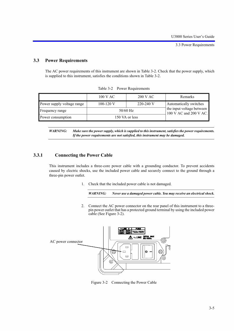
3.3 Power Requirements
The AC power requirements of this instrument are shown in Table 3-2. Check that the power supply, whichis supplied to this instrument, satisfies the conditions shown in Table 3-2.
WARNING: Make sure the power supply, which is supplied to this instrument, satisfies the power requirements.If the power requirements are not satisfied, this instrument may be damaged.
3.3.1 Connecting the Power Cable
This instrument includes a three-core power cable with a grounding conductor. To prevent accidentscaused by electric shocks, use the included power cable and securely connect to the ground through athree-pin power outlet.
1. Check that the included power cable is not damaged.
WARNING: Never use a damaged power cable. You may receive an electrical shock.
2. Connect the AC power connector on the rear panel of this instrument to a three-pin power outlet that has a protected ground terminal by using the included powercable (See Figure 3-2).
Figure 3-2 Connecting the Power Cable
Table 3-2 Power Requirements
100 V AC 200 V AC Remarks
Power supply voltage range 100-120 V 220-240 V Automatically switches the input voltage between 100 V AC and 200 V AC.
Frequency range 50/60 Hz
Power consumption 150 VA or less
AC power connector

U3800 Series User’s Guide
3.3.2 Power Fuse
3-6
WARNING:
• Use a suitable power cable for the power supply voltage. Use a power cable that complies with the safetystandards in your country (Refer to “Safety Summary”).
• To prevent any danger of electrical shock, connect the power cable to a three-pin power outlet that is con-nected to a protected ground terminal. The instrument will not be grounded if an extension cord, whichdoes not include a protected ground terminal, is used.
3.3.2 Power Fuse
CAUTION:
1. If the power fuse blows, there may be some problems in this instrument. Seek repair. (Refer to Chapter 9, “Maintenance.”)
2. Use the same rating and same type power fuse to prevent a fire.Rating: Time-lag 2.5 A/250 VType name: 021802.5 or FSL 250 V 2.5 A
The power fuse is placed in a fuse holder which is located on the rear panel.
The fuse holder varies depending on the AC inlet type. It is either of the two types shown in Figure 3-3.
The power fuse can be checked or replaced according to the following procedure:
1. Turn off the AC power switch on the rear panel.
2. Disconnect the power cable from the AC inlet.
3. Take out the fuse holder located on the rear panel by using a flathead screwdriver.
4. Check or replace the power fuse and put the fuse holder back in.
Figure 3-3 Replacing Power Fuse
Spare fuse

U3800 Series User’s Guide
3.4 Caution when Connecting Peripherals
3-7
3.4 Caution when Connecting Peripherals
Use shielded cables when connecting peripherals to the USB and LAN connectors on this instrument. Attach the included ferrite core (ESD-SR-120) to the cable.
Figure 3-4 Attachment of a Ferrite Core 1
When connecting an earphone to the PHONE connector, attach the included ferrite core (E04SR150718) tothe earphone cable.
Figure 3-5 Attachment of a Ferrite Core 2

U3800 Series User’s Guide
3.5 Checking Operations
3-8
3.5 Checking Operations
This section describes how to check operations by using the calibration function of this instrument. Checkthat this instrument operates correctly by following the procedure below.
Starting this instrument
1. Connect the power cable according to “3.3.1 Connecting the Power Cable”.
2. Turn on the AC power switch on the rear panel.
3. Three seconds after turning on the AC power switch on the rear panel, press thePOWER switch on the front panel to turn on the instrument.The power supply and the green power light turn on.
Figure 3-6 POWER Switch
4. The system boots up and the program starts.
5. The result of the self-diagnostics and the initial screen are displayed.The initial screen display may differ from Figure 3-7 depending on the status ofthe settings when the power supply was last turned off.
Figure 3-7 Initial Screen

U3800 Series User’s Guide
3.5 Checking Operations
3-9
MEMO: If any error message is displayed, refer to “9. Maintenance”.
Running calibration
6. Connect as shown in Figure 3-8 by using the included N-BNC adaptor and inputcable (A01037-300).
Figure 3-8 Connecting the CAL Signal
IMPORTANT: Perform calibration after allowing a warm up time of at least 5 minutes.For more information on how to perform autocalibration, refer to Sec-tion 4.3.1, “Level Calibration”.
7. Press the SYSTEM key of this instrument and select Calibration from the softmenu.
8. Select Calibrate ALL on the next soft menu. It takes approximately five minutes to complete the autocalibration of each chan-nel. When the calibration of channel 1 is complete, change the signal connection tochannel 2.
9. Check that no error message is displayed at the end of the calibration.
MEMO: If any error message is displayed, refer to “9. Maintenance”.
Turning off the power supply
10. Press the POWER switch on the front panel.The power supply and the power light turn off.


U3800 Series User’s Guide
4. Instrument Configuration and Basic Operations
4-1
4. Instrument Configuration and Basic Operations
This chapter describes the functions of each part on the panels and screen, and describes the basic operationsof this instrument by using measurement examples.
4.1 Panel and Screen Descriptions
This section describes the names and functions of each part on the front panel, screen, and rear panel.
4.1.1 Names and Functions of Each Part on the Front Panel
This section describes the names and functions of each part on the front panel.
Figure 4-1 Front Panel
1. POWER switch with lamp Switches the power supply between ON and OFF.The lamp turns on while the power turns on
2. Extended function key block The keys in this block set the extended functions.
3. PHONE connector Earphone terminal for demodulated AM and FM audio signals
4. USB connector Enables a USB memory device to be connected.
5. Color LCD Displays measurement data or setting conditions.
6. Soft key block The keys in this block select items from the soft menu on the dis-play.
1 2 4 5 6 7 8 93

U3800 Series User’s Guide
4.1.1 Names and Functions of Each Part on the Front Panel
4-2
7. Input connector lamp Indicates the active channel on which key input operations work.
8. Input and output connectors block The connectors in this block are used in measurements.
9. Operation key block The keys in this block are used for changing settings.
4.1.1.1 Extended Function Key Block
Figure 4-2 Extended Function Key Block
1. SELECT key Switches the active window.
SYNC mode setting Pressing the SHIFT and SELECT keys turns synchronous modeon and off.
Synchronous mode lamp When this instrument is operating in synchronous mode, this lampilluminates.
2. LOCAL key Cancels the remote control function.
REMOTE lamp The lamp turns on when the instrument is in the remote state.
3. SYSTEM setting Sets the operation mode of this instrument and the operationalconditions of the interface.
Preset key Pressing the SHIFT and SYSTEM keys initializes the settings ofthis instrument.
4. APPLI key Switches between the applications of this instrument.
5. DISP key Sets the measuring window and limit line display, and switchesthe display mode.
6. RECALL key Recalls and displays setting conditions and trace data.
SAVE key Pressing the SHIFT and RECALL keys saves setting conditionsand trace data.
1
2
3
4
5
6
7
8

U3800 Series User’s Guide
4.1.1 Names and Functions of Each Part on the Front Panel
4-3
7. COPY key Saves the screen data to an USB memory device.
HELP key Pressing the SHIFT and COPY keys turns HELP mode on and off.In HELP mode, soft menu descriptions are displayed.
NOTE: HELP is loaded and functions when the HELP key ispressed at the first time after the power is turned on.
8. SHIFT key with lamp Sets the shift mode which allows the functions indicated by theblue font to be selected. Turns on while the shift mode is set.
4.1.1.2 Soft Key Block
Figure 4-3 Soft Key Block
1. USER Key Allocates an arbitrary soft key menu to be used.
2. Soft menu key The soft key 1 to 7 correspond with the soft menu 1 to 7 indicatedto the left respectively. Press the soft key to select the soft menu.
3. RETURN key Returns to the previous soft menu.
CLEAR key Pressing the SHIFT and RETURN keys cancels data entry mode.
1
2
3

U3800 Series User’s Guide
4.1.1 Names and Functions of Each Part on the Front Panel
4-4
4.1.1.3 Input and Output Connectors Block
Figure 4-4 Input and Output Connectors Block
1. CAL OUT/TG OUTPUT connectorOutputs the calibration signal. Outputs a signal in accordancewith the level or phase calibration.If the tracking generator option (OPT76 and OPT77) is installed,it outputs a tracking generator signal in accordance with the oper-ation.
2. CH2 RF L-INPUT connector Inputs the signal to be measured.
3. CH1 RF L-INPUT connector Inputs the signal to be measured.
Measurement frequency rangeU3841: 9 kHz - 3 GHzU3851: 9 kHz - 8 GHzU3872: 9 kHz - 8 GHz
4. CH2 RF H-INPUT connector Inputs the signal to be measured (only for U3872).
5. CH1 RF H-INPUT connector Inputs the signal to be measured (only for U3872).
Measurement frequency range: 10 MHz - 43 GHz
CAUTION:
1. Do not apply an RF power or DC voltage that exceeds the limited value to the INPUT and OUTPUT con-nectors. Be careful of static electricity. Internal circuit components such as the input attenuator and mixer maybe damaged.
2. The precision microwave connector is used as the U3872 H-INPUT connector.This connector is compatible with the K connector (K connector is a trademark of Anritsu Corporation.)and can be connected to a common SMA connector.Be careful when handling this connector because the connector is delicate and is damaged easily.Use the included adapter (HE-A-PJ) if the connection and disconnection to this connector are per-formed frequently.
1 2 3
4 5

U3800 Series User’s Guide
4.1.1 Names and Functions of Each Part on the Front Panel
4-5
4.1.1.4 Operation Key Block
Figure 4-5 Operation Key Block
1. X math Selects the function for calculating between channels 1 and 2.
2. MEAS 1 Selects a measurement mode of the time domain analysis func-tion.
3. MEAS 2 Selects transmission power measurement, pulse measurement,and other types of measurement.
4. TRACE Sets the trace function.
5. MKR Displays the marker.
6. PEAK Searches for a peak on a trace.
7. MKR Sets the values of the marker to that of another function.
8. CURSOR Displays the difference between the channels based on the verticalaxis cursor.
9. FREQUENCY Sets the center frequency.
10. SPAN Sets the frequency span.
11. AMPLITUDE Sets the level.
7
8
9
10
4
5
6
1
2
318
17
16
1514
11
19
12
13

U3800 Series User’s Guide
4.1.1 Names and Functions of Each Part on the Front Panel
4-6
12. SWEEP Sets Sweep Time, Capture Time, and Trigger.
13. BW Sets RBW, VBW, and Capture BW.
14. Keypad There are numeric keys (0 to 9) and decimal point key.
15. - (Backspace)key Enters the minus sign and corrects entered data.
16. Unit key Selects a unit and determines the entered value.
GHz Sets a unit of GHz, +dBm, or dB.
MHz Sets a unit of MHz, -dBm, sec, V, or W.
kHz Sets a unit of kHz, mV, msec, or mW.
Hz Sets a unit of Hz, sec, CH, V, or W.
Can also be used as the ENTER key
17. Step key Enters data at each step.
18. Data knob Fine tunes the entered data.
19. START/STOP key Starts or stops the sweep.

U3800 Series User’s Guide
4.1.2 Names and Functions of Each Part on the Screen
4-7
4.1.2 Names and Functions of Each Part on the Screen
This section describes the names and functions of each part on the screen of this instrument.
4.1.2.1 Spectrum Measurement
Figure 4-6 Screen Display
1. Reference level Displays the reference level setting value.
2. Amplitude scale in log mode or linear modeDisplays the amplitude scale setting in log mode.
3. Active function Displays the function enabled by the keypad or data knob.
4. Level scale Displays the level scale.
5. Center frequency or start frequencyDisplays the center frequency or start frequency.
6. Resolution bandwidth (RBW) Displays the resolution bandwidth setting value.Displays the font color of RBW in green if RBW is set in the man-ual mode.
67
8 9
3
4
5
25
1
2
17
16
151413121110
1821 20222324 19

U3800 Series User’s Guide
4.1.2 Names and Functions of Each Part on the Screen
4-8
7. User’s title Displays the description of the details of the measured data.
8. Video bandwidth (VBW) Displays the video bandwidth setting value.Displays the font color of VBW in green if VBW is set in the man-ual mode.
9. Number of times averaging is performedDisplays the set and current number of times averaging is per-formed.
10. Sweep time Displays the sweep time setting value. Displays the font color of SWP in green if SWP is set in the man-ual mode.
11. Frequency span or stop frequency Displays the frequency span or stop frequency.
12. High-sensitivity (Hi-sensitivity) Displays HiS while the preamplifier is set to On.
13. RF attenuator Displays the attenuator setting value. Displays the font color of ATT in green if ATT is set in the manualmode.
14. UNCAL message Displays UNCAL while the manual settings are inappropriate.
15. Image Suppression Displays IS while the image suppression function is set to On.
16. Level offset Displays LOF while the reference offset is set to On.
17. Frequency offset Displays FOF while the frequency offset is set to On.
18. Date Displays the current date and time.
19. Marker area Displays the marker frequency (time) and level.
20. Measurement function display Displays the currently performed measurement function.
21. Trace and trace detector Displays the selected trace mode and trace detector mode.The trace with * displayed at the beginning is the active trace.For a display of two traces or more, the trace with * is displayedat the front.
22. Trace point Displays “501 pts” while the number of trace points is set to 501points.
23. Input impedance 75 Displays “75 ” while the Input Impedance is set to 75 .
24. Active channel Displays the channel input that is set to active.
25. External reference signal Displays Ref EX1 while the external reference signal is selected.
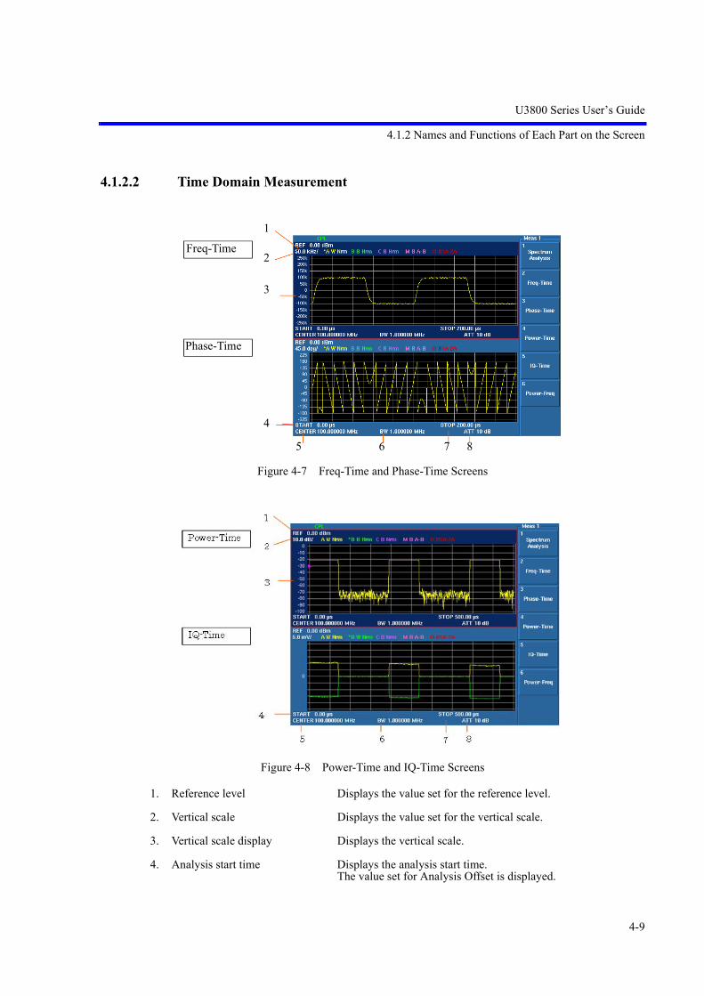
U3800 Series User’s Guide
4.1.2 Names and Functions of Each Part on the Screen
4-9
4.1.2.2 Time Domain Measurement
Figure 4-7 Freq-Time and Phase-Time Screens
Figure 4-8 Power-Time and IQ-Time Screens
1. Reference level Displays the value set for the reference level.
2. Vertical scale Displays the value set for the vertical scale.
3. Vertical scale display Displays the vertical scale.
4. Analysis start time Displays the analysis start time.The value set for Analysis Offset is displayed.
Freq-Time
Phase-Time
1
2
3
4
5 6 7 8

U3800 Series User’s Guide
4.1.2 Names and Functions of Each Part on the Screen
4-10
5. Center frequency Displays the center frequency.
6. Analysis bandwidth Displays the bandwidth in which a time domain waveform is cap-tured and analyzed. A value set for Capture BW is displayed.
7. Analysis stop time Displays the analysis stop time.
8. RF attenuator Displays the value set for the attenuator.

U3800 Series User’s Guide
4.1.3 Names and Functions of Each Part on the Rear Panel
4-11
4.1.3 Names and Functions of Each Part on the Rear Panel
This section describes the names and functions of each part on the rear panel.
Figure 4-9 Rear Panel
1. AC power connector Connects this instrument to the AC power supply by using theincluded power cable.
2. Fuse holder Contains a spare fuse.
3. AC power switch Switches the AC power ON and OFF.
4. GP-IB connector Connects to the external controller when the remote-control isused through the GPIB interface.
5. EXT TRIG IN -1 connector Inputs the external trigger signal (TTL level).
6. EXT TRIG IN-2 connector Inputs the external trigger signal (TTL level).
7. TRIG. OUT connector Outputs the trigger signal.
8. REF. IN connector Inputs the external reference signal.
9. REF. OUT connector Outputs the 10-MHz reference signal.
10. USB A connector Connects the USB memory key.
11. LAN connector LAN connector for 10/100BaseT
12. VIDEO connector Connects to an external monitor of VGA specification.
13. IF OUT connector Outputs an IF signal of 21.4 or 97.5 MHz.
1 2 3 4 5 6 7 8 9 10 11 12 13

U3800 Series User’s Guide
4.2 Basic Operation
4-12
4.2 Basic Operation
This section describes the menu operation, data entry, and usage of the basic measurement functions.
4.2.1 Menu Operation and Data Entry
Panel keys and soft menus are used to operate this instrument.
Press a panel key to display its menu to the right of the screen. Certain panel keys such as the LOCAL keydo not display a soft menu.
The menu items are arranged according to the soft keys.
The number of the menu item accords with the number of the related soft key.
Press a soft key to select the related menu.
Certain soft keys display another menu.
The following describes the functions of the panel key and soft key.
1. Selecting a menu
To set the measurement conditions, press the panel key and select the menu.
Press AMPLITUDE.
The reference level setting value is displayed in the active function display area and the followingLevel menu is displayed to the right of the screen.
1 Ref Level
2 ATT
3 dB/div
4 Vertical Scale LIN/LOG
5 Units
6 Slide Screen ON/OFF
7 More 1/2
The frame of the 1 Ref Level menu is displayed in red. This red frame menu means that data can beentered.
2. Data entry
If the set value is displayed in the active function display area, it can be changed by using keypad,step key, or data knob.
• Data entry by using the keypad
Enter data by using the keypad, decimal point key, BK SP (backspace) key, and minus (-) key.If any wrong numbers are entered by using the keypad, use the BK SP to delete a character tothe left and enter the correct number. If no data is entered and BK SP is pressed, “- (minus)” isentered.
After entering data, press the unit key (ENTER) to complete the entry.
If any other panel key is pressed before the unit key is pressed, any entered data becomes invalid.
Example: Set the reference level to -20 dBm by using the keypad.Press -, 2, 0, GHz(+dBM) or 2, 0, MHz(-dBM).

U3800 Series User’s Guide
4.2.1 Menu Operation and Data Entry
4-13
• Data entry by using the step key
The step key enters data in the defined step size. Pressing decreases data and pressing increase data.
Example: Set the reference level to 0.0 dBm by using the step key.
Press the step key . The reference level is set to -10.0 dBm. Press the step
key again to set to 0.0 dBm.
• Data entry by using the data knob
The data knob enters data in the determined display resolution. The data knob is available forthe fine adjustment of the entry data.
Example: Set the reference level to 0.5 dBm by using the data knob.Rotating the data knob in the clockwise direction increases the reference levelin steps of 0.1 dBm. Rotate the data knob until the display of the active func-tion display area shows 0.5 dBm.Rotating the data knob in the counterclockwise direction decreases the refer-ence level in steps of 0.1 dBm.
• ACTIVE OFF
Pressing the CLEAR key (SHIFT and RETURN keys) hides the active area.Data cannot be entered if the active function display area is hidden.To redisplay the active function display area, press a panel key or soft key.
3. Menu layer
Certain soft menus have at the right end and the sub menu is displayed by pressing the soft key.Certain soft menus such as ON/OFF or AUTO/MNL switch the setting by pressing the soft key.
Press MKR. The following Marker menu is displayed.
1 Select Marker
2 Marker ON/OFF
3 Marker Trace
4 Delta Mode
5 Search Menu
6 Clear All
7 More 1/2
• Switching the setting
If a menu includes a dual-state button such as ON/OFF or AUTO/MNL, the state can beswitched by pressing the soft key. The selected setting is displayed convexly.
The non-selected setting is displayed concavely.
Example: Press 2 Marker ON/OFF.The setting is turned OFF and the markers disappear.Press 2 Marker ON/OFF again to turn the setting ON and the markers re-ap-pear.
• Sub menu display
Pressing a soft key, which has to the right of the menu, displays a sub menu.
Example: Press 4 Delta Mode . The following Delta Marker menu is displayed.1 Delta ON/OFF

U3800 Series User’s Guide
4.2.1 Menu Operation and Data Entry
4-14
• RETURN
Press RETURN to return to the previous menu from the sub menu.
4. Using SHIFT
The SHIFT key is used to select the functions printed in blue on the keys.
The following functions are available:
• SYNC: Turns synchronous mode on or off.
• PRESET: Returns settings to their initial values.
• SAVE: Saves setting conditions and trace data.
• HELP: Turns the HELP function on or off.
• CLEAR: Cancels data entry mode.
• H-IN: Selects H-INPUT. (U3872)
• L-IN: Selects L-INPUT. (U3872)
• #: Turns the couple mode on or off.For more information on coupled functions, refer to Section 5.2.4.1, “Mode.”
To execute the functions written in blue on the keys, press the SHIFT key and then press the respec-tive keys.
Pressing the SHIFT key turns on its LED and the shift mode is available.
Press the SHIFT key again to cancel the shift mode. The green LED turns off and the shift mode isunavailable.
Other keys
Nothing is printed on these keys, but they have the functions shown below.
• USER Sets and cancels the USER menu.
• Select Marker Returns one selected marker number.
5. Displaying a dialog box
Pressing certain soft keys displays a dialog box.
• Selecting items and contentsSelect an item using the step key. If there are options for the selected item, turn the knob to select an option.
• Entering numeric valuesEnter values by using the keypad and unit key.
• Determining the settingPress the unit key (ENTER) to determine.

U3800 Series User’s Guide
4.3 Basic Measurement
4-15
4.3 Basic Measurement
This section describes the following basic measurements so that users can familiarize themselves with theoperation of this instrument.
• 4.3.1 Level Calibration
• 4.3.2 Selecting the Active Channel (Window)
• 4.3.3 Setting the Operation Mode and Display Mode
• 4.3.4 Displaying Trace Status
• 4.3.5 Measurement of Signals in Asynchronous Mode
• 4.3.6 How to Cancel the UNCAL Message
• 4.3.7 Identifying an Image Signal
• 4.3.8 Save/Recall
• 4.3.9 COPY (File Output to USB Memory)
• 4.3.10 USER Key
• 4.3.11 Time Domain Analysis
• 4.3.12 Synchronous Mode and Vector Calculation Function
• 4.3.13 Inter-channel Vector Correction

U3800 Series User’s Guide
4.3.1 Level Calibration
4-16
4.3.1 Level Calibration
Measurement accuracy can be increased by correcting measurements using calibration factors obtainedfrom level calibration.
IMPORTANT: Perform calibration after a warm-up time of 5 minutes or more.
Required equipment
This instrument
Conversion adapter: N(m)-BNC(f)
Conversion adapter: BNC(f)-SMA(m) (Used for U3872 H-INPUT calibration)
Input cable: BNC(m)-BNC(m)
Turning on the power
1. Verify that the AC power switch on the rear panel is set to OFF.
2. Connect the included power cable to the AC power connector on the rear panel.
CAUTION: To prevent damage, do not apply an input voltage or frequency exceed-ing the specified range to this instrument.
3. Connect the power cable to an electrical outlet.
4. Turn on the AC power switch on the rear panel. After turning on the AC power switch, wait for three seconds or more.
5. Turn on the power switch on the front panel.
MEMO: The display may be different depending on the state of the instrument whenthe power was last turned off.
CAUTION: Remove any USB memory keys before turning the power on. Other-wise, the system will not start.
When Calibrate ALL is executed, calibration for the RF input is performed in the following order.
U3841, U3851: 1. CH12. CH2
U3872: 1. CH1 L-INPUT2. CH1 H-INPUT3. CH2 L-INPUT4. CH2 H-INPUT

U3800 Series User’s Guide
4.3.1 Level Calibration
4-17
The following describes the procedure in which the calibration is performed, taking U3872 as an example.
Connect the calibration signal used for measurement.
6. Attach the N(m)-BNC(f) adapters to the CH1 RF L-INPUT and CAL OUT con-nectors on the front panel.
Connect the N(m)-BNC(f) adapters with the included BNC(m)-BNC(m) inputcable.
Figure 4-10 Connecting CAL Signal
7. Press SYSTEM, Calibration, and Calibrate ALL.
A message for confirming the CAL signal connection is displayed.
8. Press and Hz.
Calibration starts.
The following message is displayed when the calibration of channel 1 (L-Input)is complete.
To cancel the calibration, press Hz.
Change the cable connection if calibrating channel 2.
Connect the calibrator to CH1(L-Input) connector.
Then press OK continue.
First step of calibration completed.
Connect the calibrator to CH1(H-Input) connector.
Then press OK to continue.

U3800 Series User’s Guide
4.3.1 Level Calibration
4-18
9. Attach the BNC(f)-SMA(m) adapter to the RF H-INPUT connector on the frontpanel.
Connect the BNC (m)-BNC (m) cable to the CAL OUT connector and theBNC(f)-SMA(m) adapter.
Figure 4-11 Connecting CAL Signal (CH1 H-INPUT Connector)
10. Press and select OK.
Press Hz to restart calibration.
A message is also displayed when the calibration of channel 1 (H-Input) is com-pleted. Follow the message to restart calibration from CH2 RF L-INPUT.
The following message is displayed when calibration of all necessary items iscomplete.
Press the Hz key (OK) to exit calibration.
Calibration finished.

U3800 Series User’s Guide
4.3.2 Selecting the Active Channel (Window)
4-19
4.3.2 Selecting the Active Channel (Window)
The active channel is the target channel for changing settings.
There are two methods for selecting the active channel.
1. Use the SELECT key.
The active channel is switched every time the SELECT key is pressed.
The active channel whose settings can be changed is enclosed by a red frame on the screen.
The background color of the window is also changed.
2. Use unit keys (excluding the Hz key).If a unit key is pressed when the setting input was complete, the active channels switch..
Table 4-1 Selecting the Active Channel (Window)
Operation Display screen
SHIFT, SYSTEM(PRESET)Initial screenActive channel: CH1SHIFT, SELECTCancel the synchronous mode.
SELECTActive channel: CH2
0, GHzThe center frequency for channel 2 is changed from 1.5 GHz to 0 MHz.

U3800 Series User’s Guide
4.3.3 Setting the Operation Mode and Display Mode
4-20
4.3.3 Setting the Operation Mode and Display Mode
This instrument supports the following operation modes:
1. Two channel synchronous mode (Dual Sync CH)
Channels 1 and 2 operate under the same frequency and trigger conditions.
2. Two channel asynchronous mode (Dual Async CH)Channels 1 and 2 operate under independent setting conditions. Two signals of different frequencies can be measured at the same time as though two analyzers arebeing used.
3. Two channel asynchronous couple mode (Dual Async CH, Couple CH ON)Channels 1 and 2 operate under the same setting conditions. In this operation mode, settings can be made for both channels at the same time by a single key oper-ation.
Coupled functions
Frequency CenterStartStop
SPAN SPANFull SpanZero SpanLast SpanAnalysis OffsetAnalysis Window
SWEEP Sweep TimeSweep ModeCapture Time
BW RBWVBWAll AutoCapture BW
4. One channel mode (Single CH1, Single CH2)Either channel 1 or channel 2 operates.
Operation
To switch the operation mode, press SYSTEM, Mode, and Dual Sync CH /Dual Async CH.Although the synchronous mode can be turned on or off by using SHIFT or SELECT,single mode cannot be switched to synchronous mode.
The display mode for two-channel measurement can be selected from the following three modes:
1. 2 Screens Displays channel 1 in the upper window and channel 2 in thelower window.
2. Full Screen Displays the specified channel full screen.The displayed channel becomes active.
3. Overlay Overlays channels 1 and 2 full screen.

U3800 Series User’s Guide
4.3.3 Setting the Operation Mode and Display Mode
4-21
Table 4-2 Display Mode for Two-Channel Measurement
Operation Display screen
DISPScreen, 2 Screens
DISPScreen, Full Screen CH1
DISPScreen, Full Screen CH2
DISPScreen, Overlay

U3800 Series User’s Guide
4.3.4 Displaying Trace Status
4-22
4.3.4 Displaying Trace Status
This section describes the meanings of the trace status items displayed at the top of the screen.
: Displays the active trace.
: Displays Trace A, B, or C.
: Displays the refresh mode.
W: Write
V: View
B: Blank
: Displays the selected detector.
NRM: Normal
Pos: Posi
Neg: Nega
Smp: Sample
Avg: Average
QP: Quasi Peak
EMC: EMC Average
: Trace M: Displays the in-channel calculation trace.
: Displays the trace calculational expression.
: Trace O: Displays the inter-channel calculation trace.
: Displays the trace calculational expression.
1A: 1A represents Trace A of channel 1.
2B: 2B represents Trace B of channel 2.
* A W NRM1 2 3 4
M W A-B5 3 6
O W 1A-2B7 3 8
1
2
3
4
5
6
7
8

U3800 Series User’s Guide
4.3.5 Measurement of Signals in Asynchronous Mode
4-23
4.3.5 Measurement of Signals in Asynchronous Mode
This section describes the procedure for using external signal sources to measure the frequency differenceand level difference between the two channels.
Turning on the power
Refer to Section 4.3.1, “Level Calibration”, and turn on the power of this instrument.
Connecting the instrument
Have two signal generators at hand and connect their respective signal outputs to theinput connectors for channels 1 and 2.
Figure 4-12 Asynchronous Mode Signal Measurement Connection
Setting the signal generators
Signal source 1: 50MHz -20dBm
Signal source 2: 150MHz -30dBm

U3800 Series User’s Guide
4.3.5 Measurement of Signals in Asynchronous Mode
4-24
Initializing the settings
Initialize the settings of this instrument.
1. Press SHIFTand SYSTEM(PRESET).Initial setting conditions are loaded.
* For U3872Select an input connector.
Press SHIFT and -(L-in).The L-INPUT connector is selected for both CH1 and CH2.
Setting the operation mode
2. Press SYSTEM, and SELECT(SYNC).The synchronous mode is cancelled and the SYNC lamp goes out.
Asynchronous mode is enabled and difference measuring conditions can be setfor channels 1 and 2.
Setting conditions for channel 1
3. Press FREQUENCY, 5, 0, and MHz.
The center frequency is set to 50 MHz.
4. Press SPAN, 1, 0, and MHz.
The frequency span is set to 10 MHz.
NOTE: Channel 1 is selected as the active channel by default.
Setting conditions for channel 2
5. Press SELECT.
The active channel is switched to channel 2.
6. Press FREQUENCY, 1, 0, 0, and MHz.
The center frequency is set to 100 MHz.
7. Press SPAN, 2, 0, 0, and MHz.
The frequency span is set to 200 MHz.

U3800 Series User’s Guide
4.3.5 Measurement of Signals in Asynchronous Mode
4-25
Figure 4-13 Asynchronous Mode Signal Measurement Screen
Changing the display mode to Overlay and measuring the frequency difference and level differencebetween channel 1 and channel 2 signals
8. Press DISP, Screen, and Overlay.
The display mode is switched, and the trace waveforms for channels 1 and 2 areoverlaid on each other.
The waveform for the active channel comes to the front.
9. Press CURSOR, Execute ON/OFF(ON), and Mode SGL/DUAL(DUAL).
Cursors A and B are displayed.
Cursors A and B correspond to channels 1 and 2.
The frequencies and levels in the cursor positions and the frequency differenceand the level difference between the channels are displayed.
10. Use the knob to move cursor B to the position of the channel 2 signal.

U3800 Series User’s Guide
4.3.5 Measurement of Signals in Asynchronous Mode
4-26
Figure 4-14 Frequencies and Levels in Cursor Positions

U3800 Series User’s Guide
4.3.6 How to Cancel the UNCAL Message
4-27
4.3.6 How to Cancel the UNCAL Message
The resolution bandwidth (RBW), video bandwidth (VBW), frequency span (Span), and sweep time(Sweep Time) settings affect each other.
If the combination of these settings at the time the manual settings are made is inappropriate, the UNCALmessage is displayed at the bottom to the right of the scale. If the UNCAL message is displayed, the mea-surement level accuracy cannot be guaranteed.
Change the following settings to cancel the UNCAL message.
• Expand the resolution bandwidth (RBW).
• Expand the video bandwidth (VBW).
• Slow down the sweep time (Sweep Time).
• If RBW or VBW cannot be changed, narrow down the frequency span (Span).
IMPORTANT: Accurate measurement data cannot be acquired while the UNCAL message is displayed.
Example: The same frequency is set for channels 1 and 2. The sweep time setting for channel 1 is 20 ms, which is the same as for channel 2. If the video bandwidth for channel 1 is narrowed down (from 300 kHz to 300 Hz), theUNCAL message is displayed.
Figure 4-15 UNCAL Message Displayed Screen

U3800 Series User’s Guide
4.3.6 How to Cancel the UNCAL Message
4-28
To cancel the UNCAL message while keeping the video bandwidth at 300 Hz, make the sweep time longerfrom 20 ms to 280 ms.
Figure 4-16 UNCAL Message Deleted Screen

U3800 Series User’s Guide
4.3.7 Identifying an Image Signal
4-29
4.3.7 Identifying an Image Signal
NOTE: This function is only available for the U3851 and U3872.
This instrument may display an image signal depending on the input signal.
When measuring an unknown frequency signal, the real signal and image signal must be identified beforestarting the measurement. The Image Suppression and Signal Identification functions can be used to iden-tify the image signal.
Image Suppression function
Detects image signals and automatically deletes them from the display.
Press FREQUENCY, More1/2, and Image Suppression ON/OFF.
CH1 = OFF, CH2 = ON
Figure 4-17 Operation Example of Image Suppression
“IS” is displayed at the bottom right of the screen when the Image Suppression function is on.
White font: Indicates that the calculation process of Image Suppression is correctly performed.
Red font: Indicates that the calculation process of Image Suppression is being performed or the cal-culation results are indefinite. For example, when the center frequency is changed or thefrequency of the input signal changes.
Signal Identification function
The frequencies of Image signals are shifted and displayed in each sweep.
The displayed frequencies of real signals do not change.
Press FREQUENCY, More1/2, and Signal Identification ON/OFF.

U3800 Series User’s Guide
4.3.7 Identifying an Image Signal
4-30
CH1 = Signal Identification ON
Figure 4-18 Operation Example of Signal Identification
Real signal The frequency of the image signal is shifted.

U3800 Series User’s Guide
4.3.8 Save/Recall
4-31
4.3.8 Save/Recall
Setting conditions and measurement screens used in this instrument are saved in memory so that the set-tings and screens can be recalled by reading them from the memory later.
Either normal mode or quick mode can be selected for saving or recalling data.
1. Selecting a mode
Press SYSTEM, File, and Save/Recall Mode NORM/QUICK.
NORM: Selects normal mode.
QUICK: Selects quick mode.In quick mode, 10 types of files are selected by using keys 0 to 9 on the numer-ical keypad.
Before executing Save/Recall, set the file format and the memory in which data is saved.
2. File format
There are three types of file formats, BIN, CSV, and XML.
The format to be used for recalling data is the BIN format.
Files in the CSV or XML format can be captured into a PC and then processed.
Select BIN as the file format.
Press SYSTEM, File, More1/2, File Control, and File Format BIN/CSV/XML(BIN).
3. Selecting memory
Either the internal memory or a USB memory key can be selected as the memory in which data issaved.
USB connectors are located on the front panel and the rear panel, any of which can be used.
Select USB memory key as the storage destination.
Press SYSTEM, File, More1/2, and Media.
The USB memory connected to the connector is displayed in the dialog box.
Press the step key ( or ) to select a USB memory key to use.
Press the Hz key to determine the selection.
Figure 4-19 Media Selection Dialog Box

U3800 Series User’s Guide
4.3.8 Save/Recall
4-32
4. Saving data
When saving data, all of the various setting tables such as setting conditions, trace data, and limit linesare saved.
5. Recalling data
Select an item to retrieve that is appropriate for your purposes.
When Trace is selected as the item to be recalled, the trace waveforms are recalled and the trace modeis automatically set to VIEW.
For quick recall, only setting conditions are recalled.
Table 4-3 Save/Recall Procedure (1 of 2)
Mode Normal mode Quick mode
SAVE operation 1. SHIFT, RECALL SHIFT, RECALL
2. Any key from 0 to 9
3.
RECALL 1. RECALL RECALL
2. Any key from 0 to 9
3. Use the knob to specify the file.GHz The file is selected.GHz The Recall button is selected.GHz Recall is executed.

U3800 Series User’s Guide
4.3.8 Save/Recall
4-33
Auto Save
The data and screen images are saved when the specified conditions are met.
There are three types of condition settings for saving data as follows:
1. When an event occurs with a limit line + PASS/FAIL
2. For each specified sweep count
3. For each specified time interval
Auto Save is cancelled when it reaches the specified number of files or time.
In addition, Auto Save is cancelled when the setting is made by operating the keys while in Auto Save.
Folders generated in Auto Save
adv dat lmtYYYYMMDDHHmmss
swpYYYYMMDDHHmmss
tmrYYYYMMDDHHmmss
img lmtYYYYMMDDHHmmss
swpYYYYMMDDHHmmss
tmrYYYYMMDDHHmmss
4.
Table 4-3 Save/Recall Procedure (2 of 2)
Mode Normal mode Quick mode

U3800 Series User’s Guide
4.3.9 COPY (File Output to USB Memory)
4-34
4.3.9 COPY (File Output to USB Memory)
Connecting a USB memory device
1. Connect a memory device to a USB port on the front or rear panels of this instru-ment.
2. Press SYSTEM, Config, More1/2, Screen Shot Config, and Media.
A dialog box is displayed.
Select the USB memory device using the key and confirm it with the Hz key.
Figure 4-20 USB Memory Selection Dialog Box
3. Press the Media key.
The dialog box closes.
File output
1. Selecting a file format
Select the PNG or BMP format by pressing SYSTEM, Config, More1/2, ScreenShot Config, and Image Format PNG/BMP.
2. File name
copyYYYYMMDDHHmmss.png(bmp) is used as the file name.
3. Output
Images on the screen can be saved to the USB memory device by pressing theCOPY key.

U3800 Series User’s Guide
4.3.10 USER Key
4-35
4.3.10 USER Key
A soft menu corresponding to an operation key or extended function key can be set in the USER key menu.
Operability is improved by assigning frequently used functions or functions buried deep within the menuhierarchy to the USER key menu.
How to set a function menu to the USER menu
1. Display a function menu to be set in the USER menu in the soft menu displayarea.
2. Press SHIFT and then USER.
3. Press the menu key to be set.
To cancel the setting, press any other operation key.
To continue adding other function menus to the USER menu, repeat the above proce-dure.
How to delete a function menu from the USER menu
1. Press USER to display the USER menu.
2. Press SHIFT and then USER.
3. Press the menu key to be deleted.
To delete another soft key, repeat the above procedure.

U3800 Series User’s Guide
4.3.11 Time Domain Analysis
4-36
4.3.11 Time Domain Analysis
This function analyzes changes of RF signal characteristics with time as changes of fundamental quanti-ties.
Freq-Time: Frequency versus time
Phase-Time: Phase versus time
Power-Time: Power versus time
Power-Freq: FFT spectrum analysis
IQ-Time: I/Q voltage versus time
Operating method
This section describes the operating method of the time domain analysis function through a measurementexample.
By using the time domain analysis function, changes of RF signal characteristics with time can be mea-sured as each waveform of frequency, phase, power, I/Q waveforms, or spectrum.
This section describes the FSK (Frequency Shift Keying) modulated signal measurement as an example.
Figure 4-21 Time Domain Analysis Connection
• Signal Source output
Frequency: 2450 MHz
Power: 0 dBm
Modulation Type: FSK
Frequency Deviation: 40 kHzp-p
Baseband Signal: 2 kHz

U3800 Series User’s Guide
4.3.11 Time Domain Analysis
4-37
Capturing I/Q Waveforms of RF Signal
This section describes procedures for capturing an RF signal into the internal memoryof this instrument as I/Q waveforms.
Setting the center frequency, span, and reference level
1. Press FREQUENCY, 2, 4, 5, 0, and MHz.
The center frequency is set to 2,450 MHz.
2. Press SPAN, 1, 0, 0, and kHz.
The span is set to 100 kHz.
3. Press AMPLITUDE, 0, and GHz.
The reference level is set to 0 dBm.
Setting the analysis mode of RF signals
Analyses can be performed from various viewpoints including frequency, phase,power, I/Q waveforms, and FFT spectrum by using each function of the Meas-1 menu.
1. Press MEAS1 and Freq-Time.
The analysis mode of channel 2 is set to “frequency versus time.”
MEMO: When the spectrum analysis mode is switched to the time domain analysis mode, the menus assigned tothe keys are also changed to those for the time domain analysis mode.
Table 4-4 Time Domain Analysis Mode Menu
Key name Menu Function
SPAN(HORIZONTAL) Analysis Offset Sets the analysis start point.
Analysis Window Sets the analysis time length.
AMPLITUDE(VERTICAL) Vertical Scale /div Sets the vertical display scale.
Vertical Position Sets the vertical display position.
SWEEP Capture Time Sets the capture time length of the waveform.
BW Capture BW Sets the frequency bandwidth of the waveform to be captured.

U3800 Series User’s Guide
4.3.11 Time Domain Analysis
4-38
Setting the waveform capture time and capture bandwidth
1. Press SWEEP, Capture Time, 2, 0, 0, and kHz.
The waveform capture time is set to 200 msec.
2. Press BW, Capture BW, 1, 0, 0, and kHz.
The waveform capture bandwidth is set to 100 kHz.
Starting and stopping RF signal capture
1. Press SWEEP and Sweep Mode SGL/CNT to select SGL.
The sweep mode is set to Single.
2. Press START/STOP.
Capture of an RF signal starts.
Capture automatically stops 200 msec after the capture start according to the set-tings of Capture Time (200 ms) and Sweep Mode (Single).
Freq-Time analysis
Function setting
1. Press MEAS1 and Freq-Time.
The analysis function for “frequency versus time” is selected.
Display setting
2. Press SPAN(HORIZONTAL), Analysis Offset, 0, and MHz.
The analysis time offset is set to 0 sec.
3. Press Analysis Window, 2, and kHz.
The analysis time length is set to 2 msec.
4. Press AMPLITUDE(VERTICAL), Vertical Position, 0, and Hz.
The vertical offset of the data display is set to 0 Hz.
5. Press Vertical Scale/div, 1, 0, and kHz.
The vertical scale of the data display is set to 10 kHz/div.

U3800 Series User’s Guide
4.3.11 Time Domain Analysis
4-39
Figure 4-22 Freq-Time Analysis Screen
Phase-Time analysis
Active channel setting
1. Press SELECT.
Channel 2 becomes an active channel.
Function setting
2. Press MEAS1 and Phase-Time.
The analysis function for “phase versus time” is selected.
The change in “time versus phase” can be measured. The phase is displayedwrapping at 180 degrees.
Figure 4-23 Phase-Time Analysis Screen

U3800 Series User’s Guide
4.3.11 Time Domain Analysis
4-40
Power-Time analysis
Function setting
1. Press MEAS1 and Power-Time.
The analysis function for “power versus time” is selected.
The change in “time versus power” can be measured.
Figure 4-24 Power-Time Analysis Screen
Power-Freq analysis
Function setting
1. Press MEAS1 and Power-Freq.
The FFT spectrum analysis function is selected.
Frequency components included in the specified part of the time waveform canbe measured.
The analysis start point is set by Analysis Offset. The FFT analysis time lengthis set to a specific value for each setting value of Capture BW but not set by Anal-ysis Time.
For more information, refer to Chapter 5, “Menu Map and Function Descrip-tion.”
The frequency span on the FFT spectrum display is the same as the frequencybandwidth set by Capture BW and the frequency resolution is one hundredth ofthe span (when the frequency resolution setting is AUTO).
In this measurement example, Span is 100 kHz, the frequency resolution is 1kHz, and the FFT analysis time length is 10 ms because Capture BW is 100 kHz.(For the horizontal axis of 1001 points)

U3800 Series User’s Guide
4.3.11 Time Domain Analysis
4-41
Figure 4-25 Power-Freq Analysis Screen
IQ-Time analysis
Function setting
1. Press MEAS1 and IQ-Time.
The analysis function for “I/Q voltage versus time” is selected.
When the IQ-Time analysis function is selected, an I and Q waveform are allo-cated to Trace A and Trace B, respectively.
2. Press TRACE, Trace B, Refresh, and Refresh(Write).
Trace B is set to Write.
Display setting
3. Press AMPLITUDE(VERTICAL), Vertical Position, 0, and Hz.
The vertical offset of the data display is set to 0 Hz.
4. Press Vertical Scale/div, 1, 0, 0, and kHz.
The vertical display scale is set to 100 mV/div.
5. Press START/STOP.
Refreshes the Q waveform (trace B).

U3800 Series User’s Guide
4.3.12 Synchronous Mode and Vector Calculation Function
4-42
Figure 4-26 IQ-Time Analysis Screen
4.3.12 Synchronous Mode and Vector Calculation Function
If a time domain analysis is performed in synchronous mode, a structure in which phase synchronizationcan be established between channels is formed and vector calculation analysis between channels becomesenabled.
The calculation function is enabled by the X math key.
Switching to synchronous mode
1. Press SHIFT then SELECT or SYSTEM, Mode, and Dual Sync CH.
The mode is set to synchronous mode and the lamp of the key lights up.
Setting the Math function
2. X math, Math, and Math Config.
The Math Config window is displayed.
Set an inter-channel vector arithmetic operation (Math), a domain where calcu-lation between channels is performed (in Domain), a display type (Display Type),and restraining of the signal display with the specified level or lower (Squelch).

U3800 Series User’s Guide
4.3.12 Synchronous Mode and Vector Calculation Function
4-43
Figure 4-27 Inter-Channel Vector Calculation Dialog Box
3. Press Execute ON/OFF (ON).
The calculation is executed and the result is displayed in Trace A.
Operator and application example
+: Obtain the common component of the differential signal by obtaining the vec-tor sum of two signals.
-: Obtain the differential component of the differential signal by obtaining thevector difference between two signals.
: Obtain the phase sum between two signals by multiplying those two signals.
/: Obtain the amplitude ratio and phase difference between two signals by divid-ing those two signals.
NOTE: When the results of multiplication and division ( and /) are displayed in Power-Freq, the offset of thecenter frequency is added to the frequency read value of the marker.
Figure 4-28 Image for Differential Signal Vector Addition/Subtraction

U3800 Series User’s Guide
4.3.12 Synchronous Mode and Vector Calculation Function
4-44
Figure 4-29 Inter-Channel Vector Calculation Analysis Screen

U3800 Series User’s Guide
4.3.13 Inter-channel Vector Correction
4-45
4.3.13 Inter-channel Vector Correction
This section describes how to correct the phase difference and level difference between channels.
Use measurement cables and a power divider to correct the phase difference between channels at the cableends. When the measurement cables are replaced, perform the correction again.
Select an appropriate conversion adapter in accordance with the power divider to be used.
4.3.13.1 Correction Using Built-in Signal Source
Connect the CAL.OUT connector and the power divider with cables as shown in the figure below to inputa signal to the CH1 and CH2 connector.
The signal is used for correction of 8 GHz or lower.
Figure 4-30 Inter-Channel Vector Correction Connection

U3800 Series User’s Guide
4.3.13 Inter-channel Vector Correction
4-46
Setting the synchronous mode
Press SHIFT and SELECT.Synchronous mode is set.
X math, Power Ratio Phase Diff, and Execute ON/OFF(ON).
One-point correction
Correction is performed for the currently set center frequency.
Press Vector Correction, Signal Source INT, and Get Current Corr Data.A connection confirmation message is displayed.
Select OK.
When the correction is completed, a message saying “Connection finished.” is dis-played and the status display of the Vector Correction Data menu changes from OFFto ON.
Also, VCorr (ON for enabled = green, ON for disabled = red, or OFF for disabled =nothing displayed) is displayed on the upper part of the scale.
For more information on the applicable period of vector correction data, refer to“IMPORTANT” or “5.2.13 Xmath” “5.2.13.5 Correction Data Info.”
Press the Hz key to delete the message.
IMPORTANT: Applicable period of correction dataCorrection data becomes invalid by performing the following operations. Perform the correctionagain if necessary.
- Common conditions for Current, Specific Span, and Inband1. Switch the input attenuator.(REF Level, ATT, High Sensitivity ON/OFF)2. For the U3872, switch the L/H-INPUT connector.- Individual conditions1. Current: When changed from the center frequency used when correction data is acquired.2. Specific Span: When the center frequency is changed to the outside of the correction range.3. Inband: When changed from the center frequency used when correction data is acquired.
Connect the calibrator to CH1 and CH2 connector.
Then press OK to continue.

U3800 Series User’s Guide
4.3.13 Inter-channel Vector Correction
4-47
Figure 4-31 Inter-Channel Vector Correction (before/after Correction)
Correction of full bands(U3841:3GHz, U3851: 8GHz, U3872: 8GHz)
Press Vector Correction, Signal Source INT, Get Specific Span Corr Data, and GetCorrectionData.
A message is displayed as previously described. Select OK.
When the correction is completed, a message saying “Connection finished.” is dis-played and the status display of the Vector Correction Data menu changes from OFFto ON.
Also, VCorr (ON for enabled = green, ON for disabled = red, or OFF for disabled =nothing displayed) is displayed on the upper part of the scale.
For more information on the applicable period of vector correction data, refer to“IMPORTANT” or “5.2.13 Xmath” “5.2.13.5 Correction Data Info.”
Press the Hz key to exit.
IMPORTANT: Applicable period of correction dataCorrection data becomes invalid by performing the following operations. Perform the correctionagain if necessary.
- Common conditions for Current, Specific Span, and Inband1. Switch the input attenuator.(REF Level, ATT, High Sensitivity ON/OFF)2. For the U3872, switch the L/H-INPUT connector.- Individual conditions1. Current: When changed from the center frequency used when correction data is acquired.2. Specific Span: When the center frequency is changed to the outside of the correction range.3. Inband: When changed from the center frequency used when correction data is acquired.
Before correction After correction
In the example in this figure, the phasedifference between channels is approximately45 degrees.
When the correction is completed normally:
1. The menu display in Correction changesfrom OFF to ON.
2. The phase difference between channels iscorrected to nearly 0 degrees.

U3800 Series User’s Guide
4.3.13 Inter-channel Vector Correction
4-48
4.3.13.2 Correction Using External Signal Sources
Perform one-point correction using an external signal source.
An external signal source is required for correction of the U3872 H-INPUT frequency of 8 GHz or higher.
Setting external signal source
Press Vector Correction and Signal Source INT|EXT(EXT).
The external signal source is set to EXT.
Refer to Sections Refer to Sections 5.2.13, “Xmath”, 4.3.13.1, “Power Ratio PhaseDiff”, and 2-6, “Signal Source INT|EXT.”
Figure 4-32 Correction Connection Using External Signal Source
For multiple-points correction (Specific Span and InBand) using an external signal source, refer to Section6.13, “Multiple-Points Correction Using External Signal Sources.”

U3800 Series User’s Guide
4.4 Measurement Example
4-49
4.4 Measurement Example
This section describes a measurement example of signal comparison and calculation between channels usingthe Cross Math (X Math) function.
4.4.1 Measurement of Power Ratio/Phase Difference between Channels
As a measurement example for this section, a level calibration signal of 20 MHz at -20 dBm and a signalof 20 MHz at -30 dBm from an external signal source are compared.
Correcting the phase difference between channels
Use cables and a power divider to correct the phase difference between channels at thecable ends.
Refer to Section 4.3.13, “Inter-channel Vector Correction.”
1. Press SHIFT then SELECT or SYSTEM, Mode, and Dual Sync CH.
Synchronous mode is set.
2. Press FREQENCY, 2, 0, and MHz.
The center frequency is set to 20 MHz.
3. Press X math, Power Ratio Phase Diff, and Execute ON/OFF(ON).
The Correction menu is displayed.
4. Press Vector Correction, Signal Source INT, and Get Current Corr Data.
Follow the message and select OK.
The correction is executed.

U3800 Series User’s Guide
4.4.1 Measurement of Power Ratio/Phase Difference between Channels
4-50
Connecting the input signal
Connect the calibration signal and external signal source that are to be used for mea-surement as shown in the figure.
The cables used for the above vector correction are used for measurement.
Figure 4-33 Measurement Connection of Power Ratio/Phase Difference between Channels
Selecting the input connector (for U3872)
Press SHIFT and -(L-in).
The L-INPUT connector is selected for both CH1 and CH2.
Setting the measurement conditions
Press SYSTEM, Config, Frequency Reference, and INT/EXT (EXT).The frequency reference source is set to EXT.
Press FREQUENCY, 2, 0, and MHz.The center frequency is set to 20 MHz.
Measuring the power ratio/phase difference between channels
Press X math, Power Ratio Phase Diff, and Execute ON/OFF(ON).
Press X math and Ref CH CH1/CH2(CH2).

U3800 Series User’s Guide
4.4.1 Measurement of Power Ratio/Phase Difference between Channels
4-51
The power ratio and phase difference are calculated based on CH2, which is selected.
The following table shows the relationship among the measurement, calculation result, and displayedtrace.
Figure 4-34 Power Ratio and Phase Difference Screen
Table 4-5 Relationship between Calculation Result and Displayed Trace
Trace A Trace B Trace C
Screen 1 (upper screen) Calculation result of the power ratio (CH1/CH2)
CH1 CH2
Screen 2 (lower screen) Calculation result of the phase difference (CH1/CH2)
CH1 CH2
Power ratio
Phasedifference

U3800 Series User’s Guide
4.4.2 Measurement Example with Vector Calculation Function
4-52
4.4.2 Measurement Example with Vector Calculation Function
This section observes a change of the power in which the power of channel 1 and the power of channel 2are synthesized based on the phase difference between channels by using the vector calculation function.
Setting the input signal
Set the signal level of the external signal source to -20 dBm which is the same valueas the signal level of the calibration signal.
Exiting the power ratio/phase difference measurement and using the MATH function
Press X math, Power Ratio Phase Diff, and Execute ON/OFF(OFF).The power ratio/phase difference measurement is cancelled.
Press X math, Math, and Math Config.The Math Config dialog box is displayed.
Figure 4-35 Inter-Channel Vector Calculation Dialog Box
Select items using the and keys, select the contents using the knob, and finalizethe selections using the unit keys to make the settings as follows.
Screen1
Math = CH1 + CH2in Domain: TimeDisplay Type: Power - TimeSquelch: OFF (Deselecting the check box.)
Screen2
Math = CH1 / CH2in Domain: TimeDisplay Type: Phase - TimeSquelch: OFF (Deselecting the check box.)
Select the OK button and press the Hz key to finalize the settings.
Press Math Config and Execute ON/OFF(ON).

U3800 Series User’s Guide
4.4.2 Measurement Example with Vector Calculation Function
4-53
The following table shows the relationship among the measurement, calculation result, and displayedtrace.
By changing the frequency of the external signal source, it can be observed that the power sum reaches aminimum when the phase difference is 180 degrees and a maximum when the phase difference is 0degrees, and the power sum becomes approximately 6 dB higher than the input signal level.
Reading the level difference using markers
Press MKR, PEAK, MKR, Delta Mode, and Delta ON/OFF(ON).The marker delta mode is set.The reference marker and active marker are displayed on Trace A (power sum).
Press MKR and Marker Trace.The active marker moves to Trace B (CH1) and the level difference with the referencemarker is displayed.
Figure 4-36 Synthesized Power and Phase Difference Display (Dual Display)
Trace A Trace B Trace C
Screen 1 (upper screen) Calculation result of the power sum (CH1 + CH2)
CH1 CH2
Screen 2 (lower screen) Calculation result of the phase difference (CH1/CH2)
CH1 CH2

U3800 Series User’s Guide
4.4.2 Measurement Example with Vector Calculation Function
4-54
Example in which the display mode is changed to Overlay
Figure 4-37 Synthesized Power and Phase Difference Display (Overlay Display)
Displaying only the phase difference (Trace A) on screen 2 (lower screen)
Press TRACE, Trace B, Refresh, and Blank.The display of Trace B is hidden.
Press TRACE, Trace C, Refresh, and Blank.The display of Trace C is hidden.
Changing the display mode to Overlay
Press DISP, Screen, and Overlay.The screens at the top and bottom are overlapped and displayed.
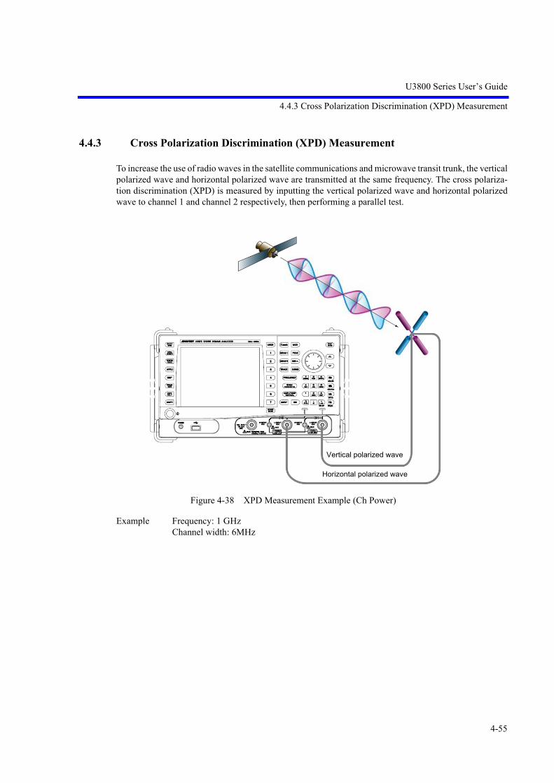
U3800 Series User’s Guide
4.4.3 Cross Polarization Discrimination (XPD) Measurement
4-55
4.4.3 Cross Polarization Discrimination (XPD) Measurement
To increase the use of radio waves in the satellite communications and microwave transit trunk, the verticalpolarized wave and horizontal polarized wave are transmitted at the same frequency. The cross polariza-tion discrimination (XPD) is measured by inputting the vertical polarized wave and horizontal polarizedwave to channel 1 and channel 2 respectively, then performing a parallel test.
Figure 4-38 XPD Measurement Example (Ch Power)
Example Frequency: 1 GHzChannel width: 6MHz
Vertical polarized wave
Horizontal polarized wave

U3800 Series User’s Guide
4.4.3 Cross Polarization Discrimination (XPD) Measurement
4-56
4.4.3.1 Using X Math Channel Power Ratio Measurement Function
Setting the measurement conditions
1. Press FREQUENCY, 1, GHz, SPAN, 2, 0, and MHz.
The center frequency is set to 1 GHz and the frequency span is set to 20 MHz.
2. Press X math and Ch Power Diff.
The CH Pow Diff menu is displayed.
3. Press Channel Width, 6, and MHz.
The channel width of channel 1 is set to 6 MHz.
4. Press SELECT, Channel Width, 6, and MHz.
The channel width of channel 2 is set to 6 MHz.
Measuring the channel power ratio
5. Press Execute ON/(OFF) ON.
Measurement of the channel power ratio starts and the result is displayed.
The trace detector is automatically set to RMS.
Figure 4-39 Channel Power Ratio Measurement

U3800 Series User’s Guide
4.4.3 Cross Polarization Discrimination (XPD) Measurement
4-57
4.4.3.2 Using Trace Calculation Function
Setting the measurement conditions
1. Press FREQUENCY, 1, GHz, SPAN, 2, 0, and MHz.
The center frequency is set to 1 GHz and the frequency span is set to 20 MHz.
2. Press TRACE, Trace A, Detector, and Average.
The trace detector of CH1 is set to RMS.
3. Press SELECT, TRACE, Trace A, Detector, and Average.
The active channel is switched and the same setting is made for CH2.
4. Press SELECT.
The active channel is returned to CH1.
5. Press TRACE, Trace Math Cross Ch, and Math Config.
The Trace Math Cross Channel dialog box is displayed.
Figure 4-40 Trace Calculation Dialog Box
Select items to be set using the and keys and the knob, and finalize theselections using the unit keys.
and keys: Item selection
Knob: Content selection
Trace Refresh Write/View/Blank (Write), GHzTrace Write is selected and the calculation result is written in Trace O.
Selecting the calculational expressionCH1-CH2/CH2-CH1 (CH2-CH1), GHz
Calculational expression CH2-CH1 is selected.
Selecting a target trace Trace A /Trace B/Trace C/Trace M (Trace A)
Math = Trace A - Trace A is set.
Selecting the calculational function (Calc)OFF/Min Hold/Max Hold(OFF)
The calculational function OFF is selected.

U3800 Series User’s Guide
4.4.3 Cross Polarization Discrimination (XPD) Measurement
4-58
Hiding the dialog box
6. Press Math Config.
The dialog box is hidden.
Adjusting the display position of the calculation result (Trace O)
7. Reference Line ON/OFF (ON), 3, 0, and MHz.
The display line is displayed at the position of -30 dBm and the position at whichthe measurement calculation result is 0 is indicated.
If the display line is set to off, zero becomes the lowest line of the scale.
Reading the result by using markers
8. Press MKR, Delta Mode, Delta ON/OFF(ON), Ref Object, and Refernce Line.
The delta marker is displayed.
The level difference between channel 1 and channel 2 is displayed in the markerarea.
Figure 4-41 XPD Measurement Example (Trace Math)

U3800 Series User’s Guide
5. Menu Map and Function Description
5-1
Operation Key Pages Operation Key Pages
5. Menu Map and Function Description
This chapter describes the configurations and functions of the soft keys displayed on the touch screen.
Menu Index: This section can be used to refer to the keys in this chapter.
Menu Map: This section shows the menu configurations of the panel keys.
Functional Descriptions: This section describes the functions of the panel keys and soft keys.
5.1 Menu Index
% OBW ................................................... 5-92%AM Meas ON|OFF .............................. 5-1140.5dB/div ................................................. 5-1551/Delta Mkr ON/OFF .............................. 5-12710dB/div .................................................. 5-1551dB/div .................................................... 5-1552 Screens ................................................. 5-51, 5-612dB/div .................................................... 5-1555dB/div .................................................... 5-155ACP ......................................................... 5-92Adjust ...................................................... 5-14Adjustment CH1 ..................................... 5-78Adjustment CH2 ..................................... 5-79All Auto .................................................. 5-174All Item ................................................... 5-11, 5-12,
5-37, 5-38Alternate IF ............................................. 5-167, 5-
168, 5-171Alternate Video ....................................... 5-166, 5-
171AM/FM Meas ......................................... 5-113AMPLITUDE ......................................... 5-154Analysis Offset ....................................... 5-66, 5-68,
5-153Analysis Window .................................... 5-66, 5-68,
5-153Annotations ON|OFF .............................. 5-17APPLI ..................................................... 5-41ATT ......................................................... 5-154, 5-
160ATT AUTO|MNL ................................... 5-155, 5-
160Attenuation 0dB ...................................... 5-155, 5-
160Auto Save ................................................ 5-27Auto Save Config .................................... 5-28Auto Tune ON|OFF ................................ 5-152
Average ................................................... 5-118, 5-120
Average Control ...................................... 5-75, 5-85, 5-87, 5-89, 5-91, 5-93, 5-97, 5-106, 5-109
Average ONCE|SLDE ............................ 5-118, 5-119
Average ONCE|SLIDE ........................... 5-76, 5-85, 5-87, 5-89, 5-91, 5-93, 5-97, 5-107, 5-109
Average PAUSE|CONT .......................... 5-107, 5-109, 5-118, 5-119
Average Power ........................................ 5-88Average START|STOP ........................... 5-118, 5-
119Averaging ................................................ 5-91Averaging ON|OFF ................................. 5-75, 5-85,
5-87, 5-89, 5-91, 5-93, 5-97
Averaging START|STOP ....................... 5-106, 5-109
Bands Definition ..................................... 5-99, 5-101Black and White ...................................... 5-18Blank ....................................................... 5-117BW .......................................................... 5-172Calc ......................................................... 5-117Calibrate ALL ......................................... 5-13Calibrate CH1 ......................................... 5-13Calibrate CH1 H-In ................................. 5-14Calibrate CH1 L-In ................................. 5-14Calibrate CH2 ......................................... 5-13

U3800 Series User’s Guide
5.1 Menu Index
5-2
Calibrate CH2 H-In ................................. 5-14Calibrate CH2 L-In ................................. 5-14Calibration .............................................. 5-13Calibration Corrections ON|OFF ............ 5-14Calibration F Int Ref ............................... 5-14Capture BW ............................................ 5-175Capture Normz Data ............................... 5-35Capture Time .......................................... 5-169Carrier Bandwidth ................................... 5-94, 5-98Center ...................................................... 5-145Center CH ON|OFF ................................ 5-147CF Step Size AUTO|MNL ...................... 5-146Ch Power Diff ......................................... 5-75Ch Select CH1|CH2 ................................ 5-16Ch Windows ON|OFF ............................. 5-94, 5-98CH1>>CH2 ............................................. 5-11, 5-37CH2>>CH1 ............................................. 5-12, 5-37Channel Config ....................................... 5-148Channel Definition .................................. 5-94Channel Input .......................................... 5-147Channel Position ..................................... 5-76, 5-85Channel Power ........................................ 5-84Channel Width ........................................ 5-76, 5-85Clear All .................................................. 5-48, 5-
134, 5-136Clear Others ............................................ 5-135Color 1 .................................................... 5-17Color 2 .................................................... 5-17Color Pattern ........................................... 5-17Conditions Definition ............................. 5-44Conditions File Recall ............................ 5-42Config ..................................................... 5-15, 5-94,
5-98, 5-129Context A|B ............................................ 5-60, 5-67,
5-68, 5-69Continuous Down ON|OFF .................... 5-133Continuous Peak ON|OFF ...................... 5-129COPY ...................................................... 5-69Copy All to Flash .................................... 5-33Copy All to USB ..................................... 5-33Corr Factor Conditions ........................... 5-49Corr SigLvl Adjust ON|OFF ................... 5-72, 5-74,
5-77Correction Data Info ............................... 5-79Correction Factor ON|OFF ..................... 5-49, 5-
158, 5-163Counter Position ..................................... 5-110Couple CH ON|OFF ............................... 5-10Couple to DL OFF|ABV|BLW ............... 5-130Couple to Line 1 OFF|ABV|BLW .......... 5-130Couple to Line 2 OFF|ABV|BLW .......... 5-131
Couple to Win OFF|IN|OUT .................. 5-130Cross Point .............................................. 5-134CURSOR ................................................ 5-143Date Time ............................................... 5-18dB/div ...................................................... 5-155dBc/Hz ON|OFF ..................................... 5-105dBm ......................................................... 5-156, 5-
161dBm/Hz ON|OFF .................................... 5-105dBmV ...................................................... 5-156, 5-
161dBpW ...................................................... 5-156, 5-
161dBuV ....................................................... 5-156, 5-
161dBuV/sqrt(Hz) ON|OFF .......................... 5-105dBuVemf ................................................. 5-156, 5-
161Default .................................................... 5-14Default Conditions .................................. 5-86, 5-88,
5-90, 5-92, 5-96, 5-100, 5-103, 5-108
Delay ....................................................... 5-167, 5-171
Delete ...................................................... 5-159, 5-164
Delete Band ............................................. 5-99, 5-102Delete Channel ........................................ 5-95Delete Entry ............................................ 5-55, 5-64,
5-131Delete Line .............................................. 5-149Delta Mode ............................................. 5-126Delta ON|OFF ......................................... 5-126Delta Ref Line ON|OFF .......................... 5-35Delta to Alternate Zoom ......................... 5-141, 5-
143Delta to CF .............................................. 5-139Delta to CF Step ...................................... 5-139Delta to Mkr Step .................................... 5-140Delta to V Scale/div ................................ 5-142Delta to Zoom ......................................... 5-139, 5-
141Det Avg Mode RMS|Video .................... 5-121Detector ................................................... 5-120Detector AUTO|MNL ............................. 5-121Differential .............................................. 5-73DISP ........................................................ 5-50Display Line ON|OFF ............................. 5-54, 5-57,
5-64, 5-65,

U3800 Series User’s Guide
5.1 Menu Index
5-3
5-130Display List ON|OFF .............................. 5-48, 5-
132, 5-135Display REL|ABL|ABR .......................... 5-133Dual Async CH ....................................... 5-10Dual Measure .......................................... 5-67Dual Measure ON|OFF ........................... 5-68Dual Sync CH ......................................... 5-10Duty Cycle .............................................. 5-112Each Channel .......................................... 5-13EBW Auto ............................................... 5-173Edit Channel Formula ............................. 5-148Edit Channel Table ................................. 5-149Edit Corr Fact .......................................... 5-164Edit Corr Factor ...................................... 5-49, 5-158Edit Date Time ........................................ 5-18EMC ........................................................ 5-173EMC Average ......................................... 5-121EMC Filter ON|OFF ............................... 5-173EMC Mode ............................................. 5-41Execute ON|OFF ..................................... 5-27, 5-71,
5-73, 5-75, 5-76, 5-85, 5-87, 5-89, 5-91, 5-93, 5-96, 5-101, 5-106, 5-108, 5-110, 5-114, 5-115, 5-144
Execute XdB Left ................................... 5-133Execute XdB Right ................................. 5-133Execute XdBm Down ............................. 5-133Ext Trigger Level .................................... 5-167, 5-
171External1 ................................................. 5-166, 5-
168, 5-170External2 ................................................. 5-166, 5-
168, 5-170Factory Init .............................................. 5-40File .......................................................... 5-22File Control ............................................. 5-20, 5-31File Format BIN|CSV|XML .................... 5-28, 5-29,
5-30, 5-33File Save ................................................. 5-49Fixed Mkr ON/OFF ................................ 5-127FM Meas ................................................. 5-115Format ..................................................... 5-18Format Media .......................................... 5-33
Formula 1 ON|OFF ................................. 5-150Formula 2 ON|OFF ................................. 5-150Formula 3 ON|OFF ................................. 5-150Free Run .................................................. 5-166, 5-
170Freq - Time ............................................. 5-66, 5-68,
5-81Freq Input Mode CALC|TABLE ............ 5-147Freq vs Time ........................................... 5-60Freq vs Time ON|OFF ............................ 5-60FREQUENCY ........................................ 5-145Frequency ................................................ 5-112Frequency Correction ON|OFF ............... 5-14Frequency Counter .................................. 5-110Frequency Offset ON|OFF ...................... 5-146Frequency Pos ......................................... 5-60Frequency Reference .............................. 5-15Frequency Reference INT|EXT|XTL ...... 5-15Full Screen CH1 ...................................... 5-51, 5-61Full Screen CH2 ...................................... 5-51, 5-61Full Span ................................................. 5-151Fundamental ON|OFF ............................. 5-109Gate Delay .............................................. 5-168Gate Width .............................................. 5-168Gated Sweep ........................................... 5-167Gated Sweep ON|OFF ............................ 5-167Get Current Corr Data ............................. 5-71, 5-74,
5-77Get Inband Corr Data .............................. 5-72, 5-74,
5-77Get Specific Span Corr Data ................... 5-72, 5-74,
5-77GPIB Address ......................................... 5-16Graph ON|OFF ........................................ 5-95Graphic Zoom 1 ON|OFF ....................... 5-58Graphic Zoom 1 Screen .......................... 5-58Graphic Zoom 2 ON|OFF ....................... 5-59Graphic Zoom 2 Screen .......................... 5-59Harmonic Max Order .............................. 5-109Harmonics ............................................... 5-108HELP ...................................................... 5-69High Sensitivity ON|OFF ....................... 5-158, 5-
163High/Low/Swing ..................................... 5-113Horizontal Scale LIN|LOG ..................... 5-49, 5-173IF ............................................................. 5-166, 5-
168, 5-171Image Format PNG|BMP ........................ 5-19, 5-28,
5-29, 5-30Image Suppression ON|OFF ................... 5-150Init Table ................................................. 5-95, 5-99,
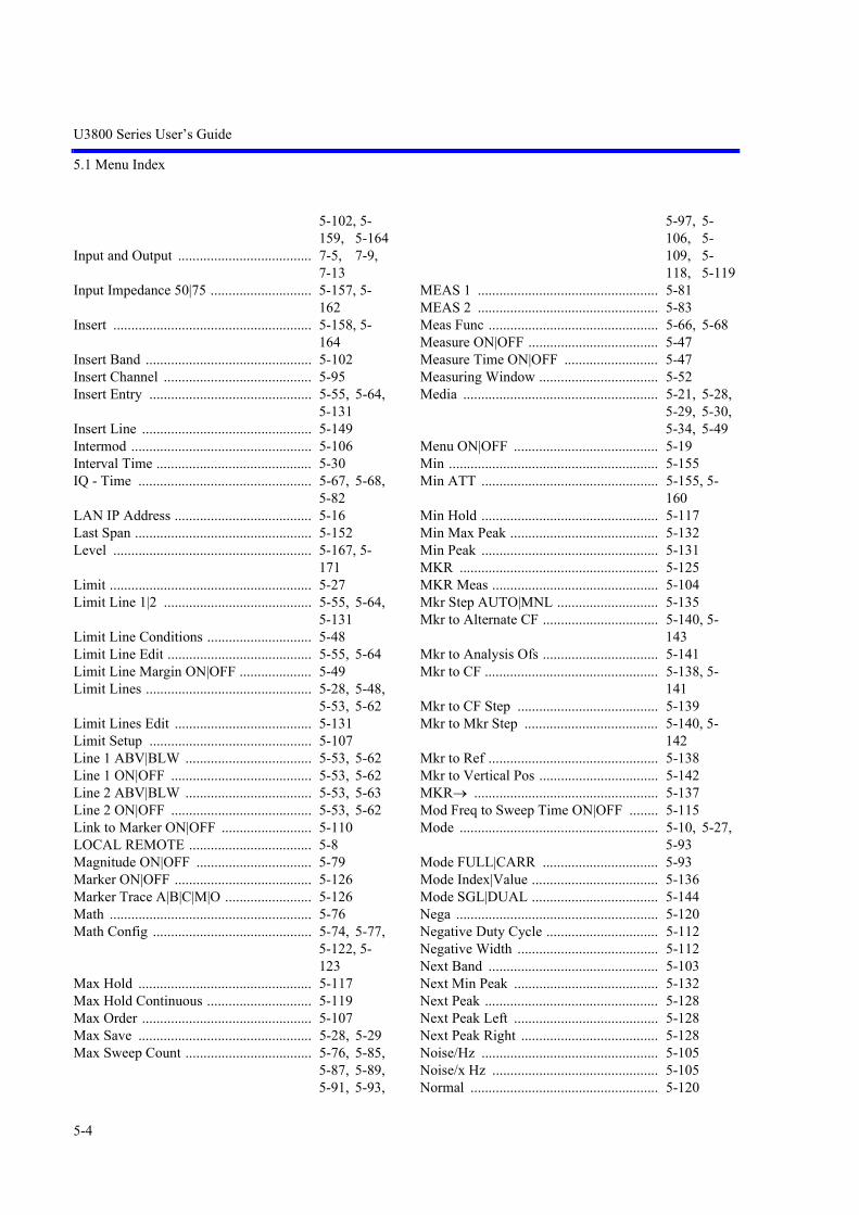
U3800 Series User’s Guide
5.1 Menu Index
5-4
5-102, 5-159, 5-164
Input and Output ..................................... 7-5, 7-9, 7-13
Input Impedance 50|75 ............................ 5-157, 5-162
Insert ....................................................... 5-158, 5-164
Insert Band .............................................. 5-102Insert Channel ......................................... 5-95Insert Entry ............................................. 5-55, 5-64,
5-131Insert Line ............................................... 5-149Intermod .................................................. 5-106Interval Time ........................................... 5-30IQ - Time ................................................ 5-67, 5-68,
5-82LAN IP Address ...................................... 5-16Last Span ................................................. 5-152Level ....................................................... 5-167, 5-
171Limit ........................................................ 5-27Limit Line 1|2 ......................................... 5-55, 5-64,
5-131Limit Line Conditions ............................. 5-48Limit Line Edit ........................................ 5-55, 5-64Limit Line Margin ON|OFF .................... 5-49Limit Lines .............................................. 5-28, 5-48,
5-53, 5-62Limit Lines Edit ...................................... 5-131Limit Setup ............................................. 5-107Line 1 ABV|BLW ................................... 5-53, 5-62Line 1 ON|OFF ....................................... 5-53, 5-62Line 2 ABV|BLW ................................... 5-53, 5-63Line 2 ON|OFF ....................................... 5-53, 5-62Link to Marker ON|OFF ......................... 5-110LOCAL REMOTE .................................. 5-8Magnitude ON|OFF ................................ 5-79Marker ON|OFF ...................................... 5-126Marker Trace A|B|C|M|O ........................ 5-126Math ........................................................ 5-76Math Config ............................................ 5-74, 5-77,
5-122, 5-123
Max Hold ................................................ 5-117Max Hold Continuous ............................. 5-119Max Order ............................................... 5-107Max Save ................................................ 5-28, 5-29Max Sweep Count ................................... 5-76, 5-85,
5-87, 5-89, 5-91, 5-93,
5-97, 5-106, 5-109, 5-118, 5-119
MEAS 1 .................................................. 5-81MEAS 2 .................................................. 5-83Meas Func ............................................... 5-66, 5-68Measure ON|OFF .................................... 5-47Measure Time ON|OFF .......................... 5-47Measuring Window ................................. 5-52Media ...................................................... 5-21, 5-28,
5-29, 5-30, 5-34, 5-49
Menu ON|OFF ........................................ 5-19Min .......................................................... 5-155Min ATT ................................................. 5-155, 5-
160Min Hold ................................................. 5-117Min Max Peak ......................................... 5-132Min Peak ................................................. 5-131MKR ....................................................... 5-125MKR Meas .............................................. 5-104Mkr Step AUTO|MNL ............................ 5-135Mkr to Alternate CF ................................ 5-140, 5-
143Mkr to Analysis Ofs ................................ 5-141Mkr to CF ................................................ 5-138, 5-
141Mkr to CF Step ....................................... 5-139Mkr to Mkr Step ..................................... 5-140, 5-
142Mkr to Ref ............................................... 5-138Mkr to Vertical Pos ................................. 5-142MKR ................................................... 5-137Mod Freq to Sweep Time ON|OFF ........ 5-115Mode ....................................................... 5-10, 5-27,
5-93Mode FULL|CARR ................................ 5-93Mode Index|Value ................................... 5-136Mode SGL|DUAL ................................... 5-144Nega ........................................................ 5-120Negative Duty Cycle ............................... 5-112Negative Width ....................................... 5-112Next Band ............................................... 5-103Next Min Peak ........................................ 5-132Next Peak ................................................ 5-128Next Peak Left ........................................ 5-128Next Peak Right ...................................... 5-128Noise/Hz ................................................. 5-105Noise/x Hz .............................................. 5-105Normal .................................................... 5-120

U3800 Series User’s Guide
5.1 Menu Index
5-5
Normalize ................................................ 5-35Normalize Correction ON|OFF ............... 5-35Nyq Roll Off Factor ................................ 5-94, 5-98Nyq Symbol Rate .................................... 5-94, 5-98Nyquist Filter ON|OFF ........................... 5-94, 5-98OBW ....................................................... 5-91OFF ......................................................... 5-112, 5-
122, 5-124On Trace A|B|C ....................................... 5-85, 5-87,
5-89, 5-92, 5-97, 5-101
On Trace A|B|C|M|O ............................... 5-76, 5-107, 5-109
Others HIDE|SHOW ............................... 5-135Overlay .................................................... 5-51, 5-61Pass/Fail Config ...................................... 5-54, 5-63Pass/Fail ON|OFF ................................... 5-53, 5-62,
5-107Pause Time .............................................. 5-114PEAK ...................................................... 5-137Peak ......................................................... 5-128Peak Delta Y ........................................... 5-48, 5-
115, 5-129Peak List ................................................. 5-48Peak List Frequency ................................ 5-48, 5-132Peak List Level ....................................... 5-48, 5-132Peak to Alternate CF ............................... 5-140Peak to CF ............................................... 5-138Peak to Ref .............................................. 5-138Peak Zoom .............................................. 5-152Peak+XdB Down .................................... 5-133Phase - Time ........................................... 5-67, 5-68,
5-81Phase Shift ON|OFF ............................... 5-79Posi .......................................................... 5-120Position View .......................................... 5-66Position View ON|OFF ........................... 5-66Positive Duty Cycle ................................ 5-112Positive Width ......................................... 5-112Power - Freq ............................................ 5-68, 5-82Power - Time .......................................... 5-67, 5-68,
5-82Power Average ........................................ 5-119Power Ratio Phase Diff ........................... 5-71Power-Freq .............................................. 5-67PRESET .................................................. 5-40Previous Band ......................................... 5-103Pulse Meas .............................................. 5-111Quasi Peak .............................................. 5-120Range FULL|WIN .................................. 5-90RBW 120kHz .......................................... 5-173
RBW 1MHz ............................................ 5-173RBW 200Hz ............................................ 5-173RBW 9kHz .............................................. 5-173RBW AUTO|MNL .................................. 5-172, 5-
176RECALL ................................................. 5-69Recall ...................................................... 5-24Ref / Disp Lines ...................................... 5-57, 5-65Ref CH CH1|CH2 ................................... 5-72, 5-74,
5-76Ref Freq .................................................. 5-15Ref Freq 10MHz ..................................... 5-15Ref Level ................................................. 5-154, 5-
159Ref Object ............................................... 5-127Ref Offset ON|OFF ................................. 5-157, 5-
162Ref Power CHN|PEAK ........................... 5-98Reference Line ........................................ 5-127Reference Line ON|OFF ......................... 5-35, 5-57,
5-65, 5-122, 5-124
Reference Marker ................................... 5-127Refresh .................................................... 5-117Refresh (Write) ....................................... 5-117Remote Control ....................................... 5-16Remove File ............................................ 5-21, 5-32Rename File ............................................ 5-20, 5-31Report HIDE|SHOW .............................. 5-14Reset Context .......................................... 5-60Resolution ............................................... 5-110Resolution 100Hz ................................... 5-110Resolution 10Hz ..................................... 5-111Resolution 1Hz ....................................... 5-111Resolution 1kHz ..................................... 5-110Restore Defaults ...................................... 5-86, 5-88,
5-90, 5-92, 5-96, 5-100, 5-103, 5-108
Results ..................................................... 5-103Round Grid Values ON|OFF .................. 5-159Sample .................................................... 5-120Sampling Data Save ................................ 5-26SAVE ...................................................... 5-69Save ......................................................... 5-22, 5-101Save As ................................................... 5-22Save Defaults .......................................... 5-86, 5-88,
5-90, 5-92, 5-96, 5-101, 5-

U3800 Series User’s Guide
5.1 Menu Index
5-6
103, 5-108Save On FAIL|PASS ............................... 5-28Save/Recall Mode NORM|QUIK ........... 5-22Screen ...................................................... 5-51, 5-61Screen SCR1|SCR2 ................................. 5-79Screen Shot Config ................................. 5-19Search Left .............................................. 5-134Search Menu ........................................... 5-127Search Right ............................................ 5-134SELECT .................................................. 5-8Select A|B ............................................... 5-144Select Marker .......................................... 5-125, 5-
128Self Test .................................................. 5-40Self Test ALL ......................................... 5-40Self Test CH1 .......................................... 5-40Self Test CH2 .......................................... 5-40Setup copy ............................................... 5-11, 5-37Setup Only .............................................. 5-11, 5-12,
5-37, 5-38SHIFT ..................................................... 5-70Shift X ON|OFF ...................................... 5-54, 5-63Shift Y ON|OFF ...................................... 5-54, 5-63Show Mask ON|OFF ............................... 5-98Show ON|OFF ........................................ 5-19Signal Identification ON|OFF ................. 5-150Signal Source INT|EXT .......................... 5-72, 5-74,
5-77Signal Track ............................................ 5-136Signal Track ON|OFF ............................. 5-136Single CH1 .............................................. 5-10Single CH2 .............................................. 5-10Slide Screen ON|OFF ............................. 5-157Slope NEG|POS ...................................... 5-167, 5-
168, 5-171Slope UP|DL|ALL ................................... 5-134Sound ...................................................... 5-114Sound AM/FM ........................................ 5-114Source ..................................................... 5-166, 5-
168, 5-170SPAN ...................................................... 5-151Span ........................................................ 5-151SPAN/RBW ON|OFF ............................. 5-174Spectrum Analysis .................................. 5-81Spectrum Emission ................................. 5-96Spurious .................................................. 5-101Start ......................................................... 5-145Start CH Offset ON|OFF ........................ 5-147Start CH ON|OFF ................................... 5-147Stop ......................................................... 5-146Stop CH Offset ON|OFF ......................... 5-147
Stop CH ON|OFF .................................... 5-147Store ........................................................ 5-14, 5-124SWEEP ................................................... 5-165Sweep ...................................................... 5-27Sweep Mode SGL|CNT .......................... 5-165, 5-
169Sweep Step .............................................. 5-29Sweep Time AUTO|MNL ....................... 5-165SYNC ...................................................... 5-8SYSTEM ................................................. 5-9Table Edit ................................................ 5-131Table File Recall(CSV) .......................... 5-56, 5-64,
5-95, 5-100, 5-102, 5-131, 5-149, 5-159, 5-164
Table File Save(CSV) ............................. 5-56, 5-64, 5-95, 5-100, 5-102, 5-131, 5-150, 5-159, 5-164
Table Init ................................................. 5-55, 5-64, 5-149
Table No. 1|2|3 ........................................ 5-102, 5-103
Table Only .............................................. 5-11, 5-12, 5-37, 5-38
Target CH CH1|CH2 ............................... 5-28, 5-29TG ........................................................... 5-34TG Freq Offset ON|OFF ......................... 5-34TG Level ................................................. 5-34TG Level Offset ON|OFF ....................... 5-34TG ON|OFF ............................................ 5-34Threshold ON|OFF ................................. 5-113, 5-
134Through Mode ON|OFF ......................... 5-17Time ........................................................ 5-27Time Shift ON|OFF ................................ 5-79Time vs Time .......................................... 5-60Title ......................................................... 5-39Total Power ............................................. 5-86Total Time ............................................... 5-30TRACE ................................................... 5-116Trace A ................................................... 5-116Trace A|B|C|M|O .................................... 5-35, 5-124Trace B .................................................... 5-121Trace C .................................................... 5-121

U3800 Series User’s Guide
5.1 Menu Index
5-7
Trace Math Cross Ch .............................. 5-123Trace Math In Ch .................................... 5-122Trace Points 501|1001 ............................. 5-17TRC(A) ............................................... 5-124TRC(B) ............................................... 5-124TRC(C) ............................................... 5-124TRCA .................................................. 5-124TRCB .................................................. 5-124TRCC .................................................. 5-124Trig Sync ON|OFF .................................. 5-167, 5-
171Trigger .................................................... 5-166, 5-
170Trigger Out ............................................. 5-16TX Meas ................................................. 5-84Units ........................................................ 5-156, 5-
161VBW AUTO|MNL ................................. 5-172VBW/RBW ON|OFF .............................. 5-174Vector Correction ................................... 5-71, 5-73,
5-76Vector Correction Data ON|OFF ............ 5-71, 5-73,
5-77Version .................................................... 5-36Vertical Position ..................................... 5-162Vertical Scale LIN|LOG ......................... 5-156, 5-
161Vertical Scale/div .................................... 5-160Video ....................................................... 5-166, 5-
170View ........................................................ 5-117Volts ........................................................ 5-156, 5-
162Volume .................................................... 5-114VSWR ON|OFF ...................................... 5-35Watts ....................................................... 5-156, 5-
162White and Black ...................................... 5-18Width ...................................................... 5-112Window ................................................... 5-90Window HIDE|SHOW ............................ 5-52Window Position ..................................... 5-52, 5-58,
5-59, 5-90, 5-130
Window Sweep ON|OFF ........................ 5-52Window Width ........................................ 5-52, 5-58,
5-59, 5-90, 5-130
Write ....................................................... 5-117Write Protect ON|OFF ............................ 5-21, 5-33X ABS|CF|FA ......................................... 5-54, 5-63
X dB down .............................................. 5-133XdB Level ............................................... 5-133Xmath ...................................................... 5-70Xmath OFF ............................................. 5-80X-Search Axis ......................................... 5-129Y ABS|REF|DL ...................................... 5-54, 5-63Y Range ON|OFF ................................... 5-136Y-Search Axis ......................................... 5-130Zero Span ................................................ 5-151Zoom ....................................................... 5-59Zoom and Contexts ................................. 5-58Zoom ON|OFF ........................................ 5-59Zoom Position ......................................... 5-59Zoom Width ............................................ 5-60

U3800 Series User’s Guide
5.2 Function Description
5-8
5.2 Function Description
This section describes the functions of the panel keys and soft keys.
MEMO:
• indicates a panel key.
• All other names are soft menus.
5.2.1 SELECT
Switches the Active Contexts and/or Active CH.
Switches both the Active Contexts and Active CH when 2 channels are displayed on the dual screen.
Switches the Active Contexts when 1 channel is displayed on the dual screen.
Disabled for single-screen display.
Pressing the SHIFT and SELECT keys turns synchronous mode on and off.
5.2.2 SYNC
Turns synchronization between the channels on and off.
ON: LED illuminates.
OFF: LED extinguishes.
5.2.3 LOCAL REMOTE
Cancels the remote control function.
The REMOTE lamp illuminates when the instrument is in the remote state.

U3800 Series User’s Guide
5.2.4 SYSTEM
5-9
5.2.4 SYSTEM
This subsection describes how to configure this instrument.

U3800 Series User’s Guide
5.2.4 SYSTEM
5-10
5.2.4.1 Mode
1. Dual Sync CH
The two channels operate in synchronous mode.
2. Dual Async CH
Channels 1 and 2 operate independently in asynchronous mode.
3. Single CH1
Operates in the single channel mode of Channel 1.
4. Single CH2
Operates in the single channel mode of Channel 2.
5. Couple CH ON|OFF
Channels 1 and 2 operate in asynchronous mode, but the following settings are synchronized when thismode is on:
Coupled functions
a. FrequencyCenterStartStop
b. SPANSPANFull SpanZero SpanLast Span
c. BWRBWVBWSweep TimeAll Auto
SYSTEM
Mode
Dual Sync CHDual Async CHSingle CH1Single CH2Couple CH ON|OFFSetup copy

U3800 Series User’s Guide
5.2.4 SYSTEM
5-11
6. Setup copy
6-1 CH1>>CH2
Copies the setting condition of channel 1 to channel 2 and applies it.
6-1-1 All Item
Saves all setting conditions.
6-1-2 Setup Only
Saves the setting conditions.
6-1-3 Table Only
Saves the table conditions.
SYSTEM
Mode
Setup copy
CH1 >> CH2CH2 >> CH1
SYSTEM
Mode
Setup copy
CH1 >> CH2
All ItemSetup OnlyTable Only

U3800 Series User’s Guide
5.2.4 SYSTEM
5-12
6-2 CH2>>CH1
Copies the setting condition of channel 2 to channel 1 and applies it.
6-2-1 All Item
Saves all setting conditions.
6-2-2 Setup Only
Saves the setting conditions.
6-2-3 Table Only
Saves the table conditions.
NOTE: After being copied, the setting conditions and contents of the setting table for channels 1 and 2 allbecome the same. If there are tables or other data that you do not want to change, save it in a USB memory device beforecopying.
SYSTEM
Mode
Setup Copy
CH2 >> CH1
All ItemSetup OnlyTable Only

U3800 Series User’s Guide
5.2.4 SYSTEM
5-13
5.2.4.2 Calibration
1. Calibrate ALL
Performs all calibrations.
2. Each Channel
Displays the Each Channel menu.
2-1 Calibrate CH1
Calibrates channel 1.
2-2 Calibrate CH2
Calibrates channel 2.
SYSTEM
Calibration
Calibrate ALLEach ChannelReport HIDE|SHOWCalibration F Int RefCalibration Corrections ON|OFFFrequency Correction ON|OFF
SYSTEM
Calibration
Each Channel
Calibrate CH1Calibrate CH2
U3841/U3851
SYSTEM
Calibration
Each Channel
Calibrate CH1 L-InCalibrate CH1 H-InCalibrate CH2 L-InCalibrate CH2 H-In
U3872

U3800 Series User’s Guide
5.2.4 SYSTEM
5-14
2-1 Calibrate CH1 L-In
Calibrates channel 1 L-Input.
2-2 Calibrate CH1 H-In
Calibrates channel 1 H-Input.
2-3 Calibrate CH2 L-In
Calibrates channel 2 L-Input.
2-4 Calibrate CH2 H-In
Calibrates channel 2 H-Input.
3. Report HIDE|SHOW
Hides or shows the calibration results.
4. Calibration F Int Ref
Calibrates the frequency of the crystal oscillator that is used for the internal frequency reference.
4-1 Adjust
Changes the adjustment data.
4-2 Store
Saves the adjusted data.
The saved data is used even if this instrument is preset.
4-3 Default
Sets the factory default calibration data.
5. Calibration Corrections ON|OFF
Switches the calibration factor ON and OFF.
ON: Uses the CAL factor.
OFF: Does not use the CAL factor.
6. Frequency Correction ON|OFF
Switches the frequency correction function ON and OFF.
ON: Corrects the frequency characteristics.
OFF: Cancels the frequency correction function.
SYSTEM
Calibration
Calibration F Int Ref
AdjustStoreDefault

U3800 Series User’s Guide
5.2.4 SYSTEM
5-15
5.2.4.3 Config
1. Frequency Reference
Selects the signal source of the reference frequency.
1-1 Frequency Reference INT|EXT|XTL
INT: Selects the internal signal source.
EXT: Uses an external input signal from the EXT. REF connector.
XTL: Selects an optional crystal oscillator.
1-2 Ref Freq
The reference frequency can be changed by using the step keys.
The following frequencies can be set as the reference frequency:
1MHz, 1.544MHz, 2.048MHz, 5MHz, 10MHz, 12.8MHz, 13MHz, 13.824MHz, 14.4MHz, 15.36MHz, 15.4MHz, 16.8MHz, 19.2MHz, 19.44MHz, 19.6608MHz, 19.68MHz, 19.8MHz, 20MHz, 26MHz
1-3 Ref Freq 10MHz
Set the reference value to 10 MHz.
SYSTEM
Config
Frequency ReferenceRemote ControlTrigger OutTrace Points 501|1001Annotations ON|OFFColor PatternDate TimeScreen Shot Config
SYSTEM
Config
Frequency Reference
Frequency Reference INT|EXT|XTLRef FreqRef Freq 10MHz
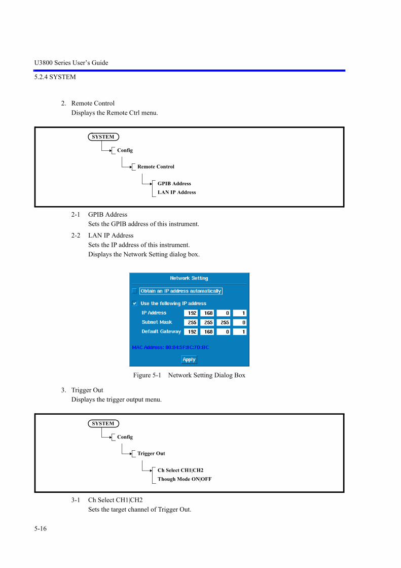
U3800 Series User’s Guide
5.2.4 SYSTEM
5-16
2. Remote Control
Displays the Remote Ctrl menu.
2-1 GPIB Address
Sets the GPIB address of this instrument.
2-2 LAN IP Address
Sets the IP address of this instrument.
Displays the Network Setting dialog box.
Figure 5-1 Network Setting Dialog Box
3. Trigger Out
Displays the trigger output menu.
3-1 Ch Select CH1|CH2
Sets the target channel of Trigger Out.
SYSTEM
Config
Remote Control
GPIB AddressLAN IP Address
SYSTEM
Config
Trigger Out
Ch Select CH1|CH2Though Mode ON|OFF

U3800 Series User’s Guide
5.2.4 SYSTEM
5-17
3-2 Through Mode ON|OFF
Sets whether to output external trigger input of the target channel to the trigger output.
4. Trace Points 501|1001
Switches the trace point in the horizontal axis between 501 and 1001.
501: Sets the trace point to 501.
1001: Sets the trace point to 1001.
5. Annotations ON|OFF
ON: Displays set values such as the center frequency on the top and bottom of the vertical scale.
OFF: Hides set values.
Zooms into the area where set values were displayed.
Figure 5-2 Annotations OFF (Left), Annotations ON (Right)
6. Color Pattern
Displays the color setting menu.
6-1 Color 1
Selects the standard color.
6-2 Color 2
Selects Color 2.
SYSTEM
Config
Color Pattern
Color 1Color 2Black and WhiteWhite and Black

U3800 Series User’s Guide
5.2.4 SYSTEM
5-18
6-3 Black and White
Selects black for the background and white for signals.
6-4 White and Black
Selects white for the background and black for signals.
7. Date Time
Displays the date menu.
7-1 Edit Date Time
Sets a date and time. They are set or changed in the dialog box.
Figure 5-3 Date and Time Setting Dialog Box
Year: Set a year.
Month: Set a month.
Day: Set a date.
Hour: Set an hour.
Minute: Set a minute.
7-2 Format
Sets date display formats.
They are set or changed in the dialog box.
SYSTEM
Config
Date Time
Edit Date TimeFormatShow ON|OFF

U3800 Series User’s Guide
5.2.4 SYSTEM
5-19
Figure 5-4 Date Display Setting Dialog Box
7-3 Show ON|OFF
Switches ON and OFF the date display.
ON: Displays the date.
OFF: Hides the date display.
8. Screen Shot Config
8-1 Image Format PNG|BMP
Selects either PNG (portable network graphics) or BMP (bitmap) as the file format.
8-2 Menu ON|OFF
Hides the soft menu area when a copy is output.
ON: Displays the menu.
OFF: Hides the menu.
SYSTEM
Config
Screen Shot Config
Image Format PNG|BMPMenu ON|OFFFile ControlMedia

U3800 Series User’s Guide
5.2.4 SYSTEM
5-20
8-3 File Control
Displays the Shot File menu.
Displays the Files window.
8-3-1 Rename File
Changes the selected filename.
Select a file name to be renamed with the cursor and press the [1. Rename File] button.
Enter a new file name in New name: by using the keypad.
After entering a new file name, press the [Hz] button.
Figure 5-5 Rename File Operation Procedure
SYSTEM
Config
Screen Shot Config
File Control
Rename FileRemove FileWrite Protect ON|OFF

U3800 Series User’s Guide
5.2.4 SYSTEM
5-21
8-3-2 Remove File
Deletes the selected file or directory (all the files in the directory).
Figure 5-6 Remove File Operation Procedure
8-3-3 Write Protect ON|OFF
Write-protects the selected file.
ON: Prevents data from being written to the file.
OFF: Allows data to be written to the file.
8-4 Media
Sets the media in which to save files.

U3800 Series User’s Guide
5.2.4 SYSTEM
5-22
5.2.4.4 File
Displays the File menu.
1. Save/Recall Mode NORM|QUIK
Sets the mode of Save or Recall to Normal or Quick.
NORM: Normal modeThe file is saved under the /adv/dat folder by pressing the [Save] or [Save As] button in themenu.
QUIK: Quick mode (Up to 10 files can be saved or recalled.)The file is saved (in one of the formats q0.dat to q9.dat under the /adv/qdat folder) by press-ing any of the numerical keys (0 to 9) of the numerical keypad after pressing the(SHIFT)+(RECALL SAVE) button.
2. Save
Saves setting conditions, trace data, and Vector Correction data in the memory specified by Media.
The format in which to save data can be selected from binary (.dat), ASCII (.csv), or XML (eXtensibleMarkup Language) (.xml).
Note: Only binary data can be saved in the internal memory of this instrument.The only format in which data can be recalled is the binary format (.dat). The ASCII CSV(Comma-Separated Values) format and the XML (eXtensible Markup Language) format(.xml) cannot be used to recall data.
3. Save As
Displays the Save As window.
Saves a file under a specified name.
To move the cursor to File name:, use the step keys ( and keys next to the knob).
After the cursor has been moved to File name:, enter a file name by using the keypad.
After confirming the file name, position the cursor on the [Save] button with the step keys, and thenpress the [Hz] button to execute Save.
SYSTEM
File
Save/Recall Mode NORM|QUIKSaveSave AsRecallSampling Data SaveAuto SaveFile ControlMedia

U3800 Series User’s Guide
5.2.4 SYSTEM
5-23
Figure 5-7 Save As Operation Procedure
Creates a directory.
Select the Create New Directory button, and then press the [Hz] button.
Enter a new directory name in New Name: in the Create New Directory window by using the keypad.
Figure 5-8 Directory Creation Procedure

U3800 Series User’s Guide
5.2.4 SYSTEM
5-24
Moves to a directory.
Allow the cursor to appear in the list of file or directory names and position it on the desired directoryby using the knob.
Pressing the [Hz] button moves the user to that directory.
Figure 5-9 Directory Movement Procedure
4. Recall
Recalls files saved in binary format and displays items specified by Items.
Displays the Recall window.
Allow the cursor to appear in the list of file or directory names and position it on the file name to berecalled by using the knob. Position the cursor on the [Recall] button by using the step keys. Pressingthe [Hz] button executes Recall.

U3800 Series User’s Guide
5.2.4 SYSTEM
5-25
Figure 5-10 Recall Operation Procedure
a. ItemsSets recall conditions.
NOTE: If all of the following checkboxes are unchecked, the file is not recalled.
1) Setup
Checked: All the conditions from when the file was saved are recalled.
Unchecked: The conditions are not recalled.
2) Trace
Checked: The trace waveform from when the file was saved is recalled.
Unchecked: The trace waveform is not recalled.
3) Table
Checked: The table values from when the file was saved are recalled.
Unchecked: The table values are not recalled.
4) Vector Correction
Checked: Vector Correction data from when the file was saved, is recalled.
Unchecked: Vector Correction data is not recalled.

U3800 Series User’s Guide
5.2.4 SYSTEM
5-26
If Recall is executed with the Trace checkbox checked, the screen switches to View mode. If sweep isstarted, the waveform is not updated. The setting of Refresh for Trace must be changed from View toRefresh (Write).
To uncheck the Trace checkbox, select a file to be recalled, select the Trace checkbox with the stepkeys, and then press the [Hz] button.
Figure 5-11 Recall Condition Setting
5. Sampling Data Save
Saves sampling data in a file.
The SWEEP setting is Sweep Mode SGL and the setting is effective when the MEAS1 setting is any-thing other than Spectrum Analysis.

U3800 Series User’s Guide
5.2.4 SYSTEM
5-27
6. Auto Save
Saves data in a file automatically for each sweep, at specified time intervals, or according to PASS/FAIL results.
6-1 Execute ON|OFF
ON: Turns on Auto Save.
OFF: Turns off Auto Save.
6-2 Mode
6-2-1 Limit
Saves data in a file automatically according to the Limit Line and PASS/FAIL results.
6-2-2 Sweep
Saves data in a file automatically for each sweep.
6-2-3 Time
Saves data in a file automatically at specified intervals.
SYSTEM
File
Auto Save
Execute ON|OFFModeAuto Save ConfigMedia
SYSTEM
File
Auto Save
Mode
LimitSweepTime

U3800 Series User’s Guide
5.2.4 SYSTEM
5-28
6-3 Auto Save Config
When Mode is Limit
6-3-1 Save On FAIL|PASS
Saves data in a file according to the Limit Line and PASS/FAIL results.
6-3-2 Max Save
Sets the maximum number of files to be saved.
6-3-3 Limit Lines
Displays the Limit Line menu.
6-3-4 Target CH CH1|CH2
Sets a target channel.
6-3-5 Image Format PNG|BMP
Selects either PNG (portable network graphics) or BMP (bitmap) as the file format.
6-3-6 File Format BIN|CSV|XML
BIN: Saves the data in binary format. Only binary formats can be saved in the internal memory. The settings of files saved in binary format can be recalled.
CSV: Saves the data in ASCII format.
XML: Saves the data in XML format. Files which are saved in XML format can be read easily but the settings cannot berecalled.
6-3-7 Media
Sets the media in which to save files.
Displays the Media dialog box.
Select either the internal memory or an external USB memory device in the dialog box.
SYSTEM
File
Auto Save
Auto Save Config
Save On FAIL|PASSlMax SaveLimit LinesTarget CH CH1|CH2Image Format PNG|BMPFile Format BIN|CSV|XMLMedia
DISP
Limit Line

U3800 Series User’s Guide
5.2.4 SYSTEM
5-29
When Mode is Sweep
6-3-1 Sweep Step
Sets the interval at which data is saved for each sweep.
6-3-2 Max Save
Sets the maximum number of files to be saved.
Up to 100 files can be set in the internal memory.
Up to 100000 files can be set in the USB memory.
6-3-3 Target CH CH1|CH2
Sets a target channel.
6-3-4 Image Format PNG|BMP
Selects either PNG (portable network graphics) or BMP (bitmap) as the file format.
6-3-5 File Format BIN|CSV|XML
BIN: Saves the data in binary format. Only binary formats can be saved in the internal memory. The settings of files saved in binary format can be recalled.
CSV: Saves the data in ASCII format.
XML: Saves the data in XML format. Files which are saved in XML format can be read easily but the settings cannot berecalled.
6-3-6 Media
Sets the media in which to save files.
Displays the Media dialog box.
Select either the internal memory or an external USB memory device in the dialog box.
SYSTEM
File
Auto Save
Auto Save Config
Sweep StepMax SaveTarget CH CH1|CH2Image Format PNG|BMPFile Format BIN|CSV|XMLMedia

U3800 Series User’s Guide
5.2.4 SYSTEM
5-30
When Mode is Time
6-3-1 Interval Time
Sets the time interval (time: 1 second to 1,000 seconds) at which data is saved.
6-3-2 Total Time
Sets the time (from 1 second to 10,000 seconds) over which data is saved in a file.
6-3-3 Image Format PNG|BMP
Selects either PNG (portable network graphics) or BMP (bitmap) as the file format.
6-3-4 File Format BIN|CSV|XML
BIN: Saves the data in binary format. Only binary formats can be saved in the internal memory. The settings of files saved in binary format can be recalled.
CSV: Saves the data in ASCII format.
XML: Saves the data in XML format. Files which are saved in XML format can be read easily but the settings cannot berecalled.
6-3-5 Media
Sets the media in which to save files.
Displays the Media dialog box.
Select either the internal memory or an external USB memory device in the dialog box.
6-4 Media
Sets the media in which to save files.
Displays the Media dialog box.
Select either the internal memory or an external USB memory device in the dialog box.
SYSTEM
File
Auto Save
Auto Save Config
Interval TimeTotal TimeImage Format PNG|BMPFile Format BIN|CSV|XMLMedia

U3800 Series User’s Guide
5.2.4 SYSTEM
5-31
7. File Control
Displays the File Control menu and Files window.
7-1 Rename File
Changes the selected filename.
Select a file name to be renamed with the cursor and press the [1. Rename File] button.
Enter a new file name in New name: by using the keypad.
After entering a new file name, press the [Hz] button.
SYSTEM
File
File Control
Rename FileRemove FileWrite Protect ON|OFFCopy All to FlashCopy All to USBFile Format BIN|CSV|XMLFormat Media

U3800 Series User’s Guide
5.2.4 SYSTEM
5-32
Figure 5-12 Rename File Operation Procedure
7-2 Remove File
Deletes the selected file or directory (all the files in the directory).

U3800 Series User’s Guide
5.2.4 SYSTEM
5-33
Figure 5-13 Remove File Operation Procedure (Directory)
7-3 Write Protect ON|OFF
Write-protects the selected file.
ON: Prevents data from being written to the file.
OFF: Allows data to be written to the file.
7-4 Copy All to Flash
Copies all files in the USB memory key to the internal memory (Refer to the note).
7-5 Copy All to USB
Copies all files in the internal memory to the USB memory key (refer to the note).
7-6 File Format BIN|CSV|XML
BIN: Saves the data in binary format. Only binary formats can be saved in the internal memory. The settings of files saved in binary format can be recalled.
CSV: Saves the data in ASCII format.
XML: Saves the data in XML format. Files which are saved in XML format can be read easily but the settings cannot berecalled.
7-7 Format Media
Formats external USB memory devices.
Do not remove the memory device while the memory is being formatted.

U3800 Series User’s Guide
5.2.4 SYSTEM
5-34
8. Media
Selects the media in which to save data.
Displays the Media dialog box.
Select either the internal memory or an external USB memory device in the dialog box.
NOTE: The file format that can be copied into the USB memory key is “.dat”. The screen image cannot be copied. The .dat file is saved in the \adv\dat folder. If the same file name exists in the USB memory key, the file is overwritten. Select USB memory in Media.
5.2.4.5 TG
Displays theTG menu.
1. TG ON|OFF
ON: Turns on the tracking generator.
OFF: Turns off the tracking generator.
2. TG Level
Sets the output level of the tracking generator.
Setting range
-5 dBm to -60 dBm (OPT76)
-5 dBm to -30dBm (OPT77)
3. TG Level Offset ON|OFF
Switches the TG level offset function ON and OFF.
ON: The offset level can be set in the range of 0 100.0 dB. The relationship between the displayed TG level, set TG level, and offset is as follows: Displayed TG level = Set TG level + Offset
OFF: Cancels the offset function.
4. TG Freq Offset ON|OFF
Switches the TG frequency offset function on and off.
SYSTEM
TG
TG ON|OFFTG LevelTG Level Offset ON|OFFTG Freq Offset ON|OFFNormalizeReference Line ON|OFF

U3800 Series User’s Guide
5.2.4 SYSTEM
5-35
5. Normalize
Displays the TG Normz menu.
5-1 Capture Normz Data
Acquires the normalization data at the position of the reference line.
5-2 Normalize Correction ON|OFF
ON: Normalizes the measurement data by using the normalization data.
OFF: Cancels the Normalize function.
5-3 Trace A|B|C|M|O
Selects the trace memory in which the data to be normalized is acquired and the normalizationfunction is performed.
5-4 VSWR ON|OFF
Displays a return loss and VSWR as marker values. Before performing a measurement, normalization using the SWR bridge must be executed.
ON: Displays Return Loss and VSWR.R.L = 20 log VSWR = (1+) / (1-)
OFF: Cancels the Return Loss and VSWR displays.
5-5 Delta Ref Line ON|OFF
ON: Turns on the marker and displays the level difference from the reference line (MK).
OFF: Hides the MK display.
5-6 Reference Line ON|OFF
ON: Displays the reference line and sets its display position.
OFF: Hides the reference line.
6. Reference Line ON|OFF
ON: Displays the reference line and sets its display position.
OFF: Hides the reference line.
SYSTEM
TG
Normalize
Capture Normz DataNormalize Correction ON|OFFTrace A|B|C|M|OVSWR ON|OFFDelta Ref Line ON|OFFReference Line ON|OFF
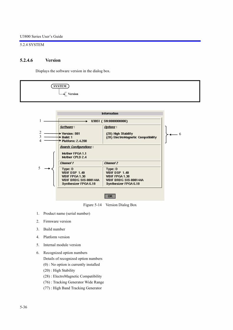
U3800 Series User’s Guide
5.2.4 SYSTEM
5-36
5.2.4.6 Version
Displays the software version in the dialog box.
Figure 5-14 Version Dialog Box
1. Product name (serial number)
2. Firmware version
3. Build number
4. Platform version
5. Internal module version
6. Recognized option numbers
Details of recognized option numbers
(0) : No option is currently installed
(20) : High Stability
(28) : ElectroMagnetic Compatibility
(76) : Tracking Generator Wide Range
(77) : High Band Tracking Generator
SYSTEM
Version
1
6234
5

U3800 Series User’s Guide
5.2.4 SYSTEM
5-37
5.2.4.7 Setup copy
1. CH1>>CH2
Copies the setting condition of channel 1 to channel 2 and applies it.
1-1 All Item
Copies all setting conditions.
1-2 Setup Only
Copies the setting conditions.
1-3 Table Only
Copies the table conditions.
2. CH2>>CH1
Copies the setting condition of channel 2 to channel 1 and applies it.
SYSTEM
Setup copy
CH1 >> CH2CH2 >> CH1
SYSTEM
Setup copy
CH1 >> CH2
All ItemSetup OnlyTable Only
SYSTEM
Setup copy
CH2 >> CH1
All ItemSetup OnlyTable Only
U3800 Series User’s Guide
5.2.4 SYSTEM
5-38
2-1 All Item
Copies all setting conditions.
2-2 Setup Only
Copies the setting conditions.
2-3 Table Only
Copies the table conditions.
NOTE: After the copy, the setting conditions and contents of the setting table for channels 1 and 2 are all thesame. If there are tables or other data that the user does not want to change, save it in a USB memory devicebefore copying.

U3800 Series User’s Guide
5.2.4 SYSTEM
5-39
5.2.4.8 Title
Displays the Edit Title dialog box.
Figure 5-15 Edit Title Dialog Box
Input method.
Pressing a key continuously cycles through a list of characters, which are allocated to that key, and displaysthem at the cursor position.
If the key is not pressed for a few seconds after the previous key entry or another key is pressed, the dis-played character is entered.
To enter a capital letter, hold down the SHIFT key and a key.
1. Enter a character by using the keypad.
2. Press a unit key such as the Hz key after entering the title.
3. Press Title to close the Edit Title dialog box.
Table 5-1 Keypad and Alphabet
Key Allocated Characters
0 0
. . Space , ; :- + _ = . # < > ! ?
- [Back Space]
1 1
2 a b c 2
3 d e f 3
4 g h i 4
5 j k l 5
6 m n o 6
7 p q r s 7
8 t u v 8
9 w x y z 9
SYSTEM
Title

U3800 Series User’s Guide
5.2.5 PRESET
5-40
5.2.4.9 Self Test
Displays the Self Test menu.
1. Self Test ALL
Executes a self-test.
2. Self Test CH1
Tests an item regarding channel 1.
3. Self Test CH2
Tests an item regarding channel 2.
5.2.4.10 Factory Init
Initializes this instrument to the factory settings.
5.2.5 PRESET
Initializes the settings of this instrument.
SYSTEM
Self Test
Self Test ALLSelf Test CH1Self Test CH2
SYSTEM
Factory Init

U3800 Series User’s Guide
5.2.6 APPLI
5-41
5.2.6 APPLI
This is a function for expansion.
5.2.6.1 EMC
Displays the EMC menu.
1. EMC Mode
ON: Sets the EMC mode to ON (uses the EMC filter mode).
OFF: Sets the EMC mode to OFF (cancels the EMC filter mode).
APPLI
EMC
EMC Mode ON|OFFConditions File RecallConditions DefinitionMedia

U3800 Series User’s Guide
5.2.6 APPLI
5-42
2. Conditions File Recall
Recalls the measurement condition file.
Figure 5-16 EMC Measure Recall Conditions Dialog Window (First Page)
(1) Select the file to be read, using the data knob.
(2) The content of the selected file is displayed.
(3) Cancel: Cancels the process.
(4) Recall: Reads the selected file and applies it to this instrument. Close the EMC Measure Recall Conditions dialog window.
(5) Next Page >>:Displays the EMC Measure Recall Conditions dialog window (second page).
APPLI
EMC
Conditions File Recall
Measure ON|OFFPeak ListFile Control
(1)
(2)
(3)
(4)(5)

U3800 Series User’s Guide
5.2.6 APPLI
5-43
Figure 5-17 EMC Measure Recall Conditions Dialog Window (Second Page)
(1) << Prev Page:Displays the EMC Measure Recall Conditions dialog window (first page).
Same as the firstpage.
The content of theselected file isdisplayed.
(1)
Same as the first page.

U3800 Series User’s Guide
5.2.6 APPLI
5-44
3. Conditions Definition
Sets measurement conditions. Measurement conditions can be saved to a file.
The data is saved in binary format (.emc).
Figure 5-18 EMC Measure Conditions Dialog Window (First Page)
(1) Enter Title information (such as measurement information).
(2) When the FREQUENCY button is selected, a pop-up window is displayed.
Ok: Sets the entered Start Freq and Stop Freq to this instrument.
Cancel: Cancels the process.
Figure 5-19 FREQUENCY Setting Pop-up Window
APPLI
EMC
Conditions Definition
(1)
(2)
(3)
(4)
(5)
(8) (7) (6)

U3800 Series User’s Guide
5.2.6 APPLI
5-45
(3) When the TRACE button is selected, a pop-up window is displayed.
Ok: Sets the selected Refresh, Calc, and Detector to this instrument.
Cancel: Cancels the process.
CAUTION:
1. If Average Detector (any of Video Avg, RMS Avg, and EMC Avg) is selected from the Detector settings forTrace A/B/C, the Average Detector settings for other traces become the same.
2. If Quasi Peak Detector is selected, Video Avg for other traces cannot be selected and RMS Avg is automaticallyset.
Figure 5-20 TRACE Setting Pop-up Window
(4) When the BANDWIDTH button is selected, a pop-up window is displayed.
Ok: Sets the entered Filter, VBW, and Sweep to this instrument.
Cancel: Cancels the process.
Figure 5-21 BANDWIDTH Setting Pop-up Window
A numeric value cannot beentered when Auto is selected.

U3800 Series User’s Guide
5.2.6 APPLI
5-46
(5) When the AMPLITUDE button is selected, a pop-up window is displayed.
Ok: Sets the entered Ref Level, ATT, and High Sensitivity to this instrument.
Cancel: Cancels the process.
Figure 5-22 AMPLITUDE Setting Pop-up Window
(6) Cancel: Cancels the process.
(7) Ok: Applies Title information to this instrument and closes the EMC Measure Conditionsdialog window.
(8) Next Page >>:Displays the EMC Measure Conditions dialog window (second page).
Figure 5-23 EMC Measure Conditions Dialog Window (Second Page)
(1) Sets LIN or LOG for Horizontal Scale.
LIN: Displays the horizontal axis in linear format.
LOG: Displays the horizontal axis in log format.
Sets ON or OFF for Measure Time.
ON: Repeats sweep until the measurement start time. Stops sweep after the specified timeelapses. Set the measurement time using keypad, step keys, and data knob.
OFF: Disables the function.
A numeric value cannot beentered when Auto is selected.
(1)
(2)
(3)
(4)
Same as thefirst page.
Same as the first page.
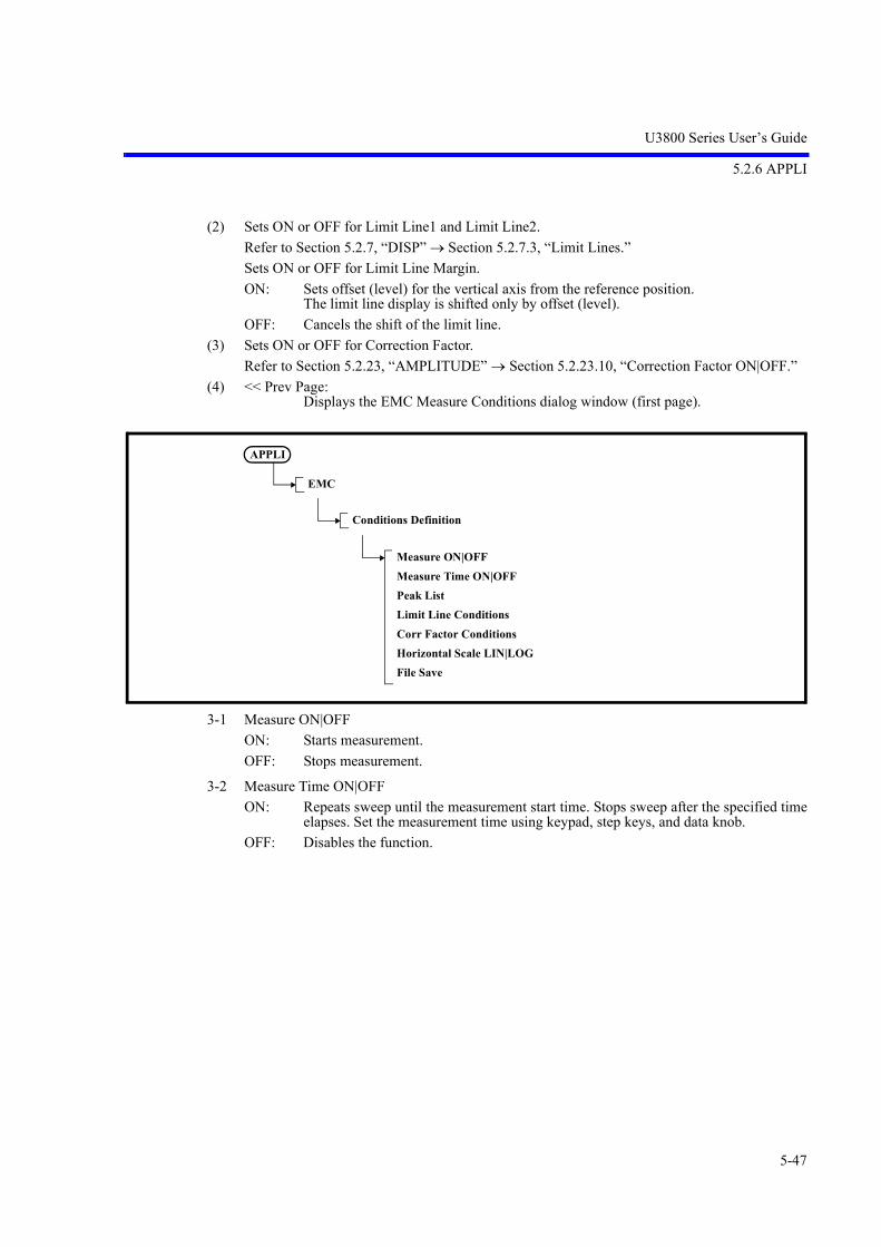
U3800 Series User’s Guide
5.2.6 APPLI
5-47
(2) Sets ON or OFF for Limit Line1 and Limit Line2.
Refer to Section 5.2.7, “DISP” Section 5.2.7.3, “Limit Lines.”
Sets ON or OFF for Limit Line Margin.
ON: Sets offset (level) for the vertical axis from the reference position. The limit line display is shifted only by offset (level).
OFF: Cancels the shift of the limit line.
(3) Sets ON or OFF for Correction Factor.
Refer to Section 5.2.23, “AMPLITUDE” Section 5.2.23.10, “Correction Factor ON|OFF.”
(4) << Prev Page:Displays the EMC Measure Conditions dialog window (first page).
3-1 Measure ON|OFF
ON: Starts measurement.
OFF: Stops measurement.
3-2 Measure Time ON|OFF
ON: Repeats sweep until the measurement start time. Stops sweep after the specified timeelapses. Set the measurement time using keypad, step keys, and data knob.
OFF: Disables the function.
APPLI
EMC
Conditions Definition
Measure ON|OFFMeasure Time ON|OFFPeak ListLimit Line ConditionsCorr Factor ConditionsHorizontal Scale LIN|LOGFile Save

U3800 Series User’s Guide
5.2.6 APPLI
5-48
3-3 Peak List
Displays the Peak List menu.
3-3-1 Peak Delta Y
Refer to Section 5.2.17, “MKR” “1. Peak” “1-5-1 Peak Delta Y.”
3-3-2 Peak List Frequency
Refer to Section 5.2.17, “MKR” “1. Peak” “1-9 Peak List Frequency.”
3-3-3 Peak List Level
Refer to Section 5.2.17, “MKR” “1. Peak” “1-10 Peak List Level.”
3-3-4 Clear All
Refer to Section 5.2.17, “MKR” Section 5.2.17.6, “Clear All”
3-3-5 Display List ON|OFF
Refer to Section 5.2.17, “MKR” “1. Peak” “1-11 Display List ON|OFF.”
3-4 Limit Line Conditions
Displays the Limit Line Conditions menu.
3-4-1 Limit Lines
Refer to Section 5.2.7, “DISP” Section 5.2.7.3, “Limit Lines.”
APPLI
EMC
Conditions Definition
Peak List
Peak Delta YPeak List FrequencyPeak List LevelClear AllDisplay List ON|OFF
APPLI
EMC
Conditions Definition
Limit Line Conditions
Limit LinesLimit Line Margin ON|OFF

U3800 Series User’s Guide
5.2.6 APPLI
5-49
3-4-2 Limit Line Margin ON|OFF
ON: Sets offset (level) for the vertical axis from the reference position. The limit line display is shifted only by offset (level).
OFF: Cancels the shift of the limit line.
3-5 Corr Factor Conditions
Displays the Corr Factor Conditions menu.
3-5-1 Correction Factor ON|OFF
Refer to Section 5.2.23, “AMPLITUDE” Section 5.2.23.10, “Correction Factor ON|OFF”
3-5-1 Edit Corr Factor
Refer to Section 5.2.23, “AMPLITUDE” Section 5.2.23.11, “Edit Corr Factor”
3-6 Horizontal Scale LIN|LOG
LIN: Displays the horizontal axis in linear format.
LOG: Displays the horizontal axis in log format.
3-7 File Save
Refer to Section 5.2.4, “SYSTEM,” Section 5.2.4.4, “File,” “3. Save As.”
Saves measurement conditions to a file. The data is saved in binary format (.emc).
4. Media
Sets the media in which to save files.
Displays the Media dialog window.
In this dialog window, select internal memory or external USB memory.
APPLI
EMC
Conditions Definition
Corr Factor Conditions
Correction Factor ON|OFFEdit Corr Factor

U3800 Series User’s Guide
5.2.7 DISP
5-50
5.2.7 DISP
Sets the display of this instrument.
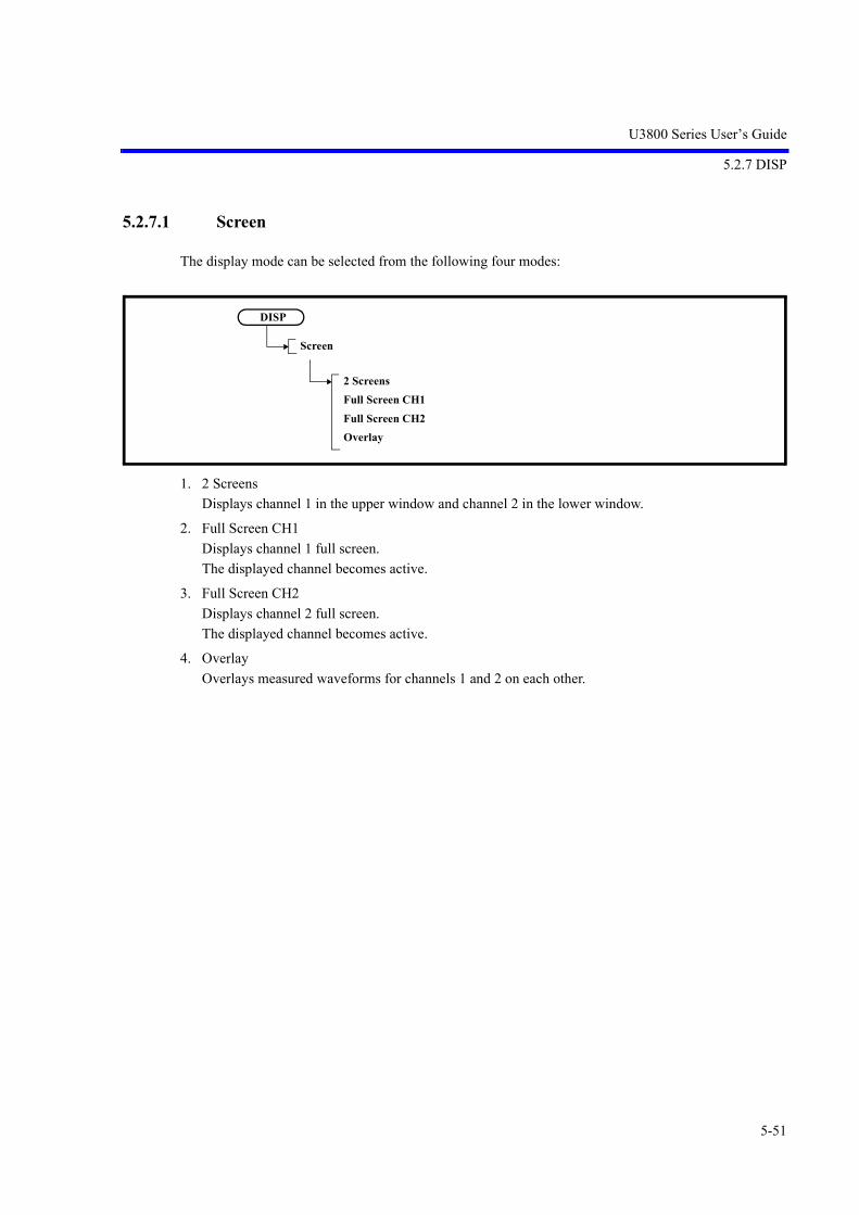
U3800 Series User’s Guide
5.2.7 DISP
5-51
5.2.7.1 Screen
The display mode can be selected from the following four modes:
1. 2 Screens
Displays channel 1 in the upper window and channel 2 in the lower window.
2. Full Screen CH1
Displays channel 1 full screen.
The displayed channel becomes active.
3. Full Screen CH2
Displays channel 2 full screen.
The displayed channel becomes active.
4. Overlay
Overlays measured waveforms for channels 1 and 2 on each other.
DISP
Screen
2 ScreensFull Screen CH1Full Screen CH2Overlay
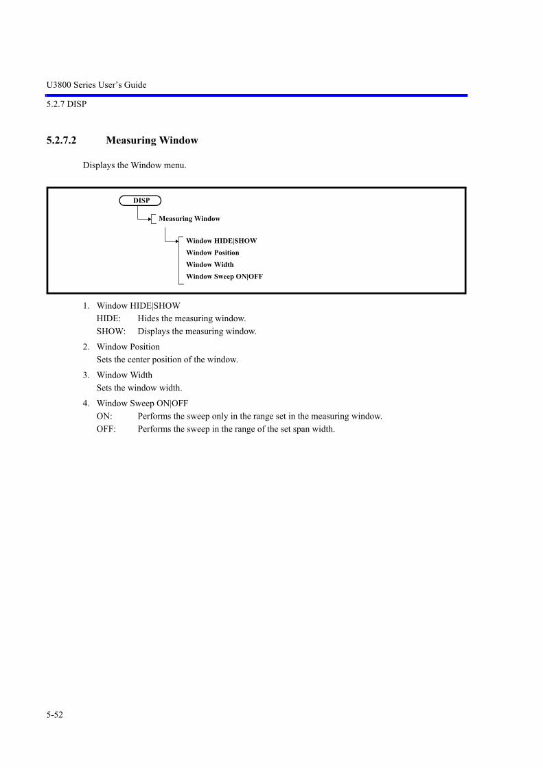
U3800 Series User’s Guide
5.2.7 DISP
5-52
5.2.7.2 Measuring Window
Displays the Window menu.
1. Window HIDE|SHOW
HIDE: Hides the measuring window.
SHOW: Displays the measuring window.
2. Window Position
Sets the center position of the window.
3. Window Width
Sets the window width.
4. Window Sweep ON|OFF
ON: Performs the sweep only in the range set in the measuring window.
OFF: Performs the sweep in the range of the set span width.
DISP
Measuring Window
Window HIDE|SHOWWindow PositionWindow WidthWindow Sweep ON|OFF

U3800 Series User’s Guide
5.2.7 DISP
5-53
5.2.7.3 Limit Lines
Displays the Pass/Fail menu.
1. Pass/Fail ON|OFF
Switches the Pass/Fail judgment ON and OFF due to the comparison with the limit value.
ON: Performs Pass/Fail judgment. Performs judgment after each sweep. If the limit line is not defined, this setting cannot be used.
OFF: Does not perform Pass/Fail judgment.
2. Line 1 ON|OFF
Switches limit line 1 ON and OFF.
ON: Displays limit line 1. When Horizontal Scale LIN is set for EMC Mode ON (EMC Filter ON), limit line 1 is dis-played as a broken line. At this point, the line is displayed as a straight line but the Pass/Fail function judges according to the Log curve line.
OFF: Hides limit line 1.
3. Line 1 ABV|BLW
Sets a judgment condition based on limit line 1.
ABV: Sets the range above limit line 1 as the PASS condition.
BLW: Sets the range below limit line 1 as the PASS condition.
4. Line 2 ON|OFF
Switches limit line 2 ON and OFF.
ON: Displays limit line 2. When Horizontal Scale LIN is set for EMC Mode ON (EMC Filter ON), limit line 2 is dis-played as a broken line. At this point, the line is displayed as a straight line but the Pass/Fail function judges according to the Log curve line.
OFF: Hides limit line 2.
5. Line 2 ABV|BLW
Sets a judgment condition based on limit line 2.
ABV: Sets the range above limit line 2 as the PASS condition.
BLW: Sets the range below limit line 2 as the PASS condition.
DISP
Limit Lines
Pass/Fail ON|OFFLine 1 ON|OFFLine 1 ABV|BLWLine 2 ON|OFFLine 2 ABV|BLWPass / Fail ConfigLimit Line Edit

U3800 Series User’s Guide
5.2.7 DISP
5-54
6. Pass/Fail Config
Displays the Pass/Fail Config menu.
6-1 X ABS|CF|FA
Sets the attributes of the horizontal axis data of the limit line.
ABS: Sets the horizontal axis position that assumes the limit line set by Limit Line Edit asthe absolute value. The horizontal axis position of the limit line moves according to changes in the fre-quency span and center frequency setting.
CF: Sets the center point of the horizontal axis as the reference position.
FA: Sets the left-most point of the horizontal axis as the reference position.
6-2 Shift X ON|OFF
ON: Sets the offset frequency from the reference position. The limit line display is shifted by the frequency offset.
OFF: Cancels the shift of the limit line.
6-3 Y ABS|REF|DL
Sets the attributes of the vertical axis (level) data of the limit line.
ABS: Sets the vertical axis position that assumes the limit line set by Limit Line Edit as theabsolute value. The vertical axis position of the limit line moves according to a change in the levelsetting.
REF: Sets the reference level as the reference position.
DL: Sets the display line as the reference position.
6-4 Shift Y ON|OFF
ON: Sets the offset (level) for the vertical axis from the reference position. The limit line display is shifted by the offset (level).
OFF: Cancels the shift of the limit line.
6-5 Display Line ON|OFF
ON: Displays the display line. Sets the position of the display line.
OFF: Hides the display line.
DISP
Limit Lines
Pass / Fail Config
X ABS|CF|FAShift X ON|OFFY ABS|REF|DLShift Y ON|OFFDisplay Line ON|OFF

U3800 Series User’s Guide
5.2.7 DISP
5-55
7. Limit Line Edit
Displays the Limit Line menu and Limit Line table.
When Horizontal Scale LOG is set for EMC Mode ON (EMC Filter ON), enter a value of 1 Hz orhigher for [Frequency].
Figure 5-24 Limit Line Edit Dialog Box
7-1 Limit Line 1|2
1: Edits limit line 1.
2: Edits limit line 2.
7-2 Delete Entry
Deletes the line on which the cursor is positioned in the limit line table.
7-3 Insert Entry
Inserts a line in the limit line table.
7-4 Table Init
Clears all settings in the limit line table.
DISP
Limit Lines
Limit Line Edit
Limit Line 1|2Delete EntryInsert EntryTable InitTable File Recall(CSV)Table File Save(CSV)
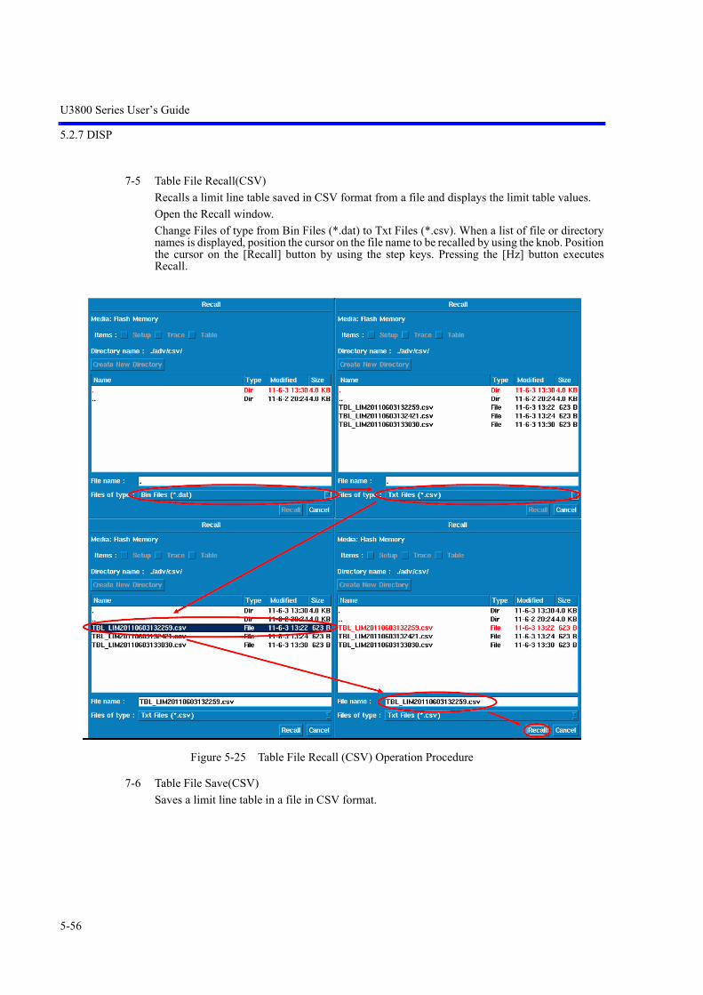
U3800 Series User’s Guide
5.2.7 DISP
5-56
7-5 Table File Recall(CSV)
Recalls a limit line table saved in CSV format from a file and displays the limit table values.
Open the Recall window.
Change Files of type from Bin Files (*.dat) to Txt Files (*.csv). When a list of file or directorynames is displayed, position the cursor on the file name to be recalled by using the knob. Positionthe cursor on the [Recall] button by using the step keys. Pressing the [Hz] button executesRecall.
Figure 5-25 Table File Recall (CSV) Operation Procedure
7-6 Table File Save(CSV)
Saves a limit line table in a file in CSV format.

U3800 Series User’s Guide
5.2.7 DISP
5-57
5.2.7.4 Ref / Disp Lines
Displays the menu.
1. Display Line ON|OFF
Switches the display of the display line, which is used as the reference line when trace levels are com-pared, between ON and OFF.
ON: Displays and activates the display line.
OFF: Hides the display line.
2. Reference Line ON|OFF
Switches the display of the reference line, which is used as the reference to display level data in relativevalue, between ON and OFF.
ON: Displays the reference line. The reference line position can be changed.
OFF: Hides the reference line.
DISP
Ref / Disp Lines
Display Line ON|OFFReference Line ON|OFF

U3800 Series User’s Guide
5.2.7 DISP
5-58
5.2.7.5 Zoom and Contexts
Displays the Zoom Contexts menu.
1. Graphic Zoom 1 Screen
Displays the G Zoom 1 menu.
1-1 Graphic Zoom 1 ON|OFF
ON: Zooms in the area selected by the window.
OFF: Cancels the zoom-in display.
1-2 Window Position
Sets the center position of the window.
1-3 Window Width
Sets the window width.
DISP
Zoom and Contexts
Graphic Z 1 ScreenGraphic Z 2 ScreenZoomFreq vs TimeTime vs TimeReset ContextContext A|B
DISP
Zoom and Contexts
Graphic Z 1 Screen
Graphic Zoom 1 ON|OFFWindow PositionWindow Width

U3800 Series User’s Guide
5.2.7 DISP
5-59
2. Graphic Zoom 2 Screen
Displays the G Zoom 2 menu.
2-1 Graphic Zoom 2 ON|OFF
ON: Splits the screen into upper and lower screens. The upper screen displays the original waveform. The lower screen zooms in on the area selected by the window.
OFF: Cancels the zoom-in display.
2-2 Window Position
Sets the center position of the window.
2-3 Window Width
Sets the window width.
3. Zoom
Displays the Zoom menu.
3-1 Zoom ON|OFF
ON: Splits the screen into upper and lower screens. The upper screen displays the original waveform. The lower screen zooms in on the frequency range selected by the window, in whichthe sweep is performed.
OFF: Cancels the dual-screen display.
3-2 Zoom Position
Sets the center position of the window.
DISP
Zoom and Contexts
Graphic Z 2 Screen
Graphic Zoom 2 ON|OFFWindow PositionWindow Width
DISP
Zoom and Contexts
Zoom
Zoom ON|OFFZoom PositionZoom WidthContext A|B

U3800 Series User’s Guide
5.2.7 DISP
5-60
3-3 Zoom Width
Sets the window width.
3-4 Context A|B
Switches the active screen between A (upper screen) and B (lower screen).
A: The upper screen settings can be changed.
B: The lower screen settings can be changed.
4. Freq vs Time
Displays the Freq vs Time menu.
4-1 Freq vs Time ON|OFF
ON: Splits the screen into upper and lower screens. The horizontal axis in the upper screen represents frequency, and the lower screen rep-resents the time (zero span) at Frequency Pos.
OFF: Cancels the dual-screen display.
4-2 Frequency Pos
Sets the frequency where the zero span is performed.
4-3 Context A|B
Switches the active screen between A (upper screen) and B (lower screen).
A: The upper screen settings can be changed.
B: The lower screen settings can be changed.
5. Time vs Time
Sets the dual-screen display and displays the horizontal axis as time for both the upper and lowerscreens.
The display of the horizontal axis in time is retained even if the dual-screen has been cancelled by usingReset Context.
Re-set SPAN to display the horizontal axis in frequency.
6. Reset Context
Cancels the dual-screen display.
7. Context A|B
Switches the active screen between A (upper screen) and B (lower screen).
A: The upper screen settings can be changed.
B: The lower screen settings can be changed.
DISP
Zoom and Contexts
Freq vs Time
Freq vs Time ON|OFFFrequency PosContext A|B

U3800 Series User’s Guide
5.2.7 DISP
5-61
5.2.7.6 Screen
NOTE: This is a menu that is displayed when the setting of MEAS1 is anything other than SPECTRUM ANAL-YSIS.
The display mode can be selected from the following four modes:
1. 2 Screens
Displays channel 1 in the upper window and channel 2 in the lower window.
2. Full Screen CH1
Displays channel 1 full screen.
The displayed channel becomes active.
3. Full Screen CH2
Displays channel 2 full screen.
The displayed channel becomes active.
4. Overlay
Overlays measured waveforms for channels 1 and 2 on each other.
DISP
Screen
2 ScreensFull Screen CH1Full Screen CH2Overlay

U3800 Series User’s Guide
5.2.7 DISP
5-62
5.2.7.7 Limit Lines
NOTE: This is a menu that is displayed when the setting of MEAS1 is anything other than SPECTRUM ANAL-YSIS.
Displays the Pass/Fail menu.
1. Pass/Fail ON|OFF
Switches the Pass/Fail judgment ON and OFF due to the comparison with the limit value.
ON: Performs Pass/Fail judgment. Performs judgment after each sweep. If the limit line is not defined, this setting cannot be used.
OFF: Does not perform Pass/Fail judgment.
2. Line 1 ON|OFF
Switches limit line 1 ON and OFF.
ON: Displays limit line 1. When Horizontal Scale LIN is set for EMC Mode ON (EMC Filter ON), limit line 1 is dis-played as a broken line. At this point, the line is displayed as a straight line but the Pass/Fail function judges according to the Log curve line.
OFF: Hides limit line 1.
3. Line 1 ABV|BLW
Sets a judgment condition based on limit line 1.
ABV: Sets the range above limit line 1 as the PASS condition.
BLW: Sets the range below limit line 1 as the PASS condition.
4. Line 2 ON|OFF
Switches limit line 2 ON and OFF.
ON: Displays limit line 2. When Horizontal Scale LIN is set for EMC Mode ON (EMC Filter ON), limit line 2 is dis-played as a broken line. At this point, the line is displayed as a straight line but the Pass/Fail function judges according to the Log curve line.
OFF: Hides limit line 2.
DISP
Limit Lines
Pass/Fail ON|OFFLine 1 ON|OFFLine 1 ABV|BLWLine 2 ON|OFFLine 2 ABV|BLWPass/Fail ConfigLimit Line Edit

U3800 Series User’s Guide
5.2.7 DISP
5-63
5. Line 2 ABV|BLW
Sets a judgment condition based on limit line 2.
ABV: Sets the range above limit line 2 as the PASS condition.
BLW: Sets the range below limit line 2 as the PASS condition.
6. Pass/Fail Config
Displays the Pass/Fail Config menu.
6-1 X ABS|CF|FA
Sets the attributes of the horizontal axis data of the limit line.
ABS: Sets the horizontal axis position that assumes the limit line set by Limit Line Edit asthe absolute value. The horizontal axis position of the limit line moves according to changes in the fre-quency span and center frequency setting.
CF: Sets the center point of the horizontal axis as the reference position.
FA: Sets the left-most point of the horizontal axis as the reference position.
6-2 Shift X ON|OFF
ON: Sets the offset frequency from the reference position. The limit line display is shifted by the frequency offset.
OFF: Cancels the shift of the limit line.
6-3 Y ABS|REF|DL
Sets the attributes of the vertical axis (level) data of the limit line.
ABS: Sets the vertical axis position that assumes the limit line set by Limit Line Edit as theabsolute value. The vertical axis position of the limit line moves according to a change in the levelsetting.
REF: Sets the reference level as the reference position.
DL: Sets the display line as the reference position.
6-4 Shift Y ON|OFF
ON: Sets the offset (level) for the vertical axis from the reference position. The limit line display is shifted by the offset (level).
OFF: The limit line display is shifted by the offset (level).
DISP
Limit Lines
Pass/Fail Config
X ABS|CF|FAShift X ON|OFFY ABS|REF|DLShift Y ON|OFFDisplay Line ON|OFF
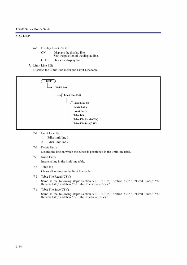
U3800 Series User’s Guide
5.2.7 DISP
5-64
6-5 Display Line ON|OFF
ON: Displays the display line. Sets the position of the display line.
OFF: Hides the display line.
7. Limit Line Edit
Displays the Limit Line menu and Limit Line table.
7-1 Limit Line 1|2
1: Edits limit line 1.
2: Edits limit line 2.
7-2 Delete Entry
Deletes the line on which the cursor is positioned in the limit line table.
7-3 Insert Entry
Inserts a line in the limit line table.
7-4 Table Init
Clears all settings in the limit line table.
7-5 Table File Recall(CSV)
Same as the following steps: Section 5.2.7, “DISP,” Section 5.2.7.3, “Limit Lines,” “7-1Rename File,” and then “7-5 Table File Recall(CSV).”
7-6 Table File Save(CSV)
Same as the following steps: Section 5.2.7, “DISP,” Section 5.2.7.3, “Limit Lines,” “7-1Rename File,” and then “7-6 Table File Save(CSV).”
DISP
Limit Lines
Limit Line Edit
Limit Line 1|2Delete EntryInsert EntryTable InitTable File Recall(CSV)Table File Save(CSV)

U3800 Series User’s Guide
5.2.7 DISP
5-65
5.2.7.8 Ref / Disp Lines
NOTE: This is a menu that is displayed when the setting of MEAS1 is anything other than SPECTRUM ANAL-YSIS.
Displays the menu.
1. Display Line ON|OFF
Switches the display of the display line, which is used as the reference line when trace levels are com-pared, between ON and OFF.
ON: Displays and activates the display line.
OFF: Hides the display line.
2. Reference Line ON|OFF
Switches the display of the reference line, which is used as the reference to display level data in relativevalue, between ON and OFF.
ON: Displays the reference line. The reference line position can be changed.
OFF: Hides the reference line.
DISP
Ref / Disp Lines
Display Line ON|OFFReference Line ON|OFF

U3800 Series User’s Guide
5.2.7 DISP
5-66
5.2.7.9 Position View
NOTE:
1. This is a menu that is displayed when the setting of MEAS1 is anything other than SPECTRUM ANALYSIS.
2. It is enabled when SYSTEM Mode Single CH1 Single CH2.
Displays the Position View menu.
1. Position View ON|OFF
ON: Zooms in the area selected by the window.
OFF: Cancels the zoom-in display.
2. Analysis Offset
Sets the analysis start point (Offset time from the top of the captured waveform) of the measured signalwaveform captured in the analyzer. (Refer to Section 5.2.25.7, “Capture BW.”)
3. Analysis Window
Sets the analysis time length (time that starts at the Analysis Offset setting value) of the measured sig-nal waveform captured in the analyzer. (Refer to Section 5.2.25.7, “Capture BW.”)
4. Meas Func
Selects which analysis function is to be displayed with the horizontal and vertical axes.
4-1 Freq - Time
Selects the analysis function for “frequency versus time.”
DISP
Position View
Position View ON|OFFAnalysis OffsetAnalysis WindowMeas FuncContext A|B
DISP
Position View
Meas Func
Freq-TimePhase-TimePower-TimeIQ-TimePower-FreqContext A|B

U3800 Series User’s Guide
5.2.7 DISP
5-67
4-2 Phase - Time
Selects the analysis function for “phase versus time.”
4-3 Power - Time
Selects the analysis function for “power versus time.”
4-4 IQ - Time
Selects the analysis function for “voltage versus time.”
4-5 Power-Freq
Enables the analysis function for “power versus frequency.”
4-6 Context A|B
Switches the active screen between A (upper screen) and B (lower screen).
A: The upper screen settings can be changed.
B: The lower screen settings can be changed.
5. Context A|B
Switches the active screen between A (upper screen) and B (lower screen).
A: The upper screen settings can be changed.
B: The lower screen settings can be changed.
5.2.7.10 Dual Measure
NOTE:
1. This is a menu that is displayed when the setting of MEAS1 is anything other than SPECTRUM ANALYSIS.
2. It is enabled when SYSTEM Mode Single CH1 Single CH2.
Displays the Dual Measure menu.
DISP
Dual Measure
Dual Measure ON|OFFAnalysis OffsertAnalysis WindowMeas FuncContext A|B

U3800 Series User’s Guide
5.2.7 DISP
5-68
1. Dual Measure ON|OFF
ON: Sets the Dual Measure function. The screen is split into upper and lower screens.The upper and lower screens display theanalysis results of the same captured waveform data. Different analysis functions can be set individually to the upper and lower screens. Also, the vertical axis display position, vertical axis scale, analysis start time, and analysistime length can be set for each screen.
OFF: Cancels the Dual Measure function.
2. Analysis Offset
Sets the analysis start point (Offset time from the top of the captured waveform) of the measured signalwaveform captured in the analyzer. (Refer to Section 5.2.25.7, “Capture BW.”)
3. Analysis Window
Sets the analysis time length (time that starts at the Analysis Offset setting value) of the measured sig-nal waveform captured in the analyzer. (Refer to Section 5.2.25.7, “Capture BW.”)
4. Meas Func
Displays the Meas Func menu.
4-1 Freq - Time
Selects the analysis function for “frequency versus time.”
4-2 Phase - Time
Selects the analysis function for “phase versus time.”
4-3 Power - Time
Selects the analysis function for “power versus time.”
4-4 IQ- Time
Selects the analysis function for “IQ data versus time.”
4-5 Power - Freq
Selects the analysis function for “power versus frequency.”
4-6 Context A|B
Switches the active screen between A (upper screen) and B (lower screen).
A: The upper screen settings can be changed.
B: The lower screen settings can be changed.
DISP
Dual Measure
Meas Func
Freq-TimePhase-TimePower-TimeIQ-TimePower-FreqContext A|B

U3800 Series User’s Guide
5.2.8 RECALL
5-69
5. Context A|B
Switches the active screen between A (upper screen) and B (lower screen).
A: The upper screen settings can be changed.
B: The lower screen settings can be changed.
5.2.8 RECALL
Refer to Section 5.2.4, “SYSTEM,” Section 5.2.4.4, “File,” and “4. Recall.”
5.2.9 SAVE
Refer to Section 5.2.4, “SYSTEM,” Section 5.2.4.4, “File,” and “2. Save.”
5.2.10 COPY
Outputs a screen image to a file according to the conditions set by SYSTEM, Config, MORE 1/2, CopyConfig , Screen Shot Config, and Image Format.
File size (For saving the image data)
PNG: Approximately 8 KB
BMP: Approximately 150 KB
5.2.11 HELP
Pressing the HELP key displays “HELP?,” which indicates the HELP mode is enabled.
CAUTION: The HELP file is loaded the first time the HELP key is pressed after the power is turned on.
When the HELP mode is set
Press a soft menu key to display the relevant menu description.
Press the soft menu key again to hide the display.
Press the HELP key again to cancel the HELP mode.

U3800 Series User’s Guide
5.2.12 SHIFT
5-70
How to use the Help key
1. Select a menu.
2. Press the Help key.
3. Press a soft menu key.
4. Press the HELP key to cancel the HELP mode.
5. Repeat from step 1 to display HELP information for other menus.
5.2.12 SHIFT
Whether the SHIFT key is on or off is indicated by an LED.
An LED illuminates when the SHIFT key is on.
5.2.13 Xmath
Sets Xmath of this instrument.

U3800 Series User’s Guide
5.2.13 Xmath
5-71
5.2.13.1 Power Ratio Phase Diff
Displays the Power ratio and the phase difference of both channels.
Displays the Power ratio as “power versus time” on Screen 1.
Displays the phase difference as “phase versus time” on Screen 2.
1. Execute ON|OFF
ON : Displays the Power ratio and the phase difference of both channels.
OFF: Does not display the Power ratio and the phase difference of both channels.
2. Vector Correction
Corrects the phase of the channel.
2-1 Vector Correction Data ON|OFF
ON: Enables vector correction data.
OFF: Disables vector correction data.
Note: If vector correction data has been already acquired, ON and OFF can be switched.
2-2 Get Current Corr Data
Corrects the phase and amplitude differences between channels.
Xmath
Power Ratio Phase Diff
Execute ON|OFFVector CorrectionRef CH CH1|CH2
Xmath
Power Ratio Phase Diff
Vector Correction
Vector Correction Data ON|OFFGet Current Corr DataGet Specific Span Corr DataGet Inband Corr DataCorr SigLvl Adjust ON|OFFSignal Source INT|EXT

U3800 Series User’s Guide
5.2.13 Xmath
5-72
2-3 Get Specific Span Corr Data
Corrects within the specified frequency range.
Figure 5-26 Vector Correction Config Dialog Window
Default Conditions:Sets Start Freq, Stop Freq, and Step Freq to the default values.
Start Freq: Enters the frequency where correction starts.
Stop Freq: Enters the frequency where correction stops.
Step Freq: Enters the correction interval frequency.
Get Corr Data: Starts correction.
Apply: Applies the entered setting value.
Cancel: Cancels operation.
IMPORTANTSpecify the frequency within the following ranges:U3841: 1 MHz to 3 GHzU3851: 1 MHz to 8 GHzU3872: 1 MHz to 8 GHz (L-Input, H-Input, internal signal used)
Specify Step Freq so that the range is (Stop Freq - Start Freq)/1000 Step Freq 50 MHz. (Same setting in all models.)
2-4 Get Inband Corr Data
Performs correction for the data in the measurement band.
2-5 Corr SigLvl Adjust ON|OFF
ON: Adjusts the correction signal output level according to the built-in preamplifier set-ting.
OFF: Does not adjust the correction signal output level.
2-6 Signal Source INT|EXT
INT: Specified when performing correction by using an internal signal source (Correctionof 8 GHz or lower).
EXT: Specified when performing correction by using an external signal source.In this case, correction is made in accordance with the Trigger Source setting.
3. Ref CH CH1|CH2
Sets the Reference CH.

U3800 Series User’s Guide
5.2.13 Xmath
5-73
5.2.13.2 Differential
Displays the vector differential measurement for both channels.
The result calculated between the following channels is displayed on Screen 1 and Screen 2.
Screen 1 (upper) = CH1 + CH2
Screen 2 (lower) = CH1 - CH2
1. Execute ON|OFF
ON: Displays the vector differential measurement for both channels.
OFF: Does not display the vector differential measurement for both channels.
2. Vector Correction
Makes corrections between channels.
2-1 Vector Correction Data ON|OFF
ON: Enables vector correction data.
OFF: Disables vector correction data.
Note: If vector correction data has been already acquired, ON and OFF can be switched.
Xmath
Differential
Execute ON|OFFVector CorrectionRef CH CH1|CH2Math Config
Xmath
Differential
Vector Correction
Vector Correction Data ON|OFFGet Current Corr DataGet Specific Span Corr DataGet Inband Corr DataCorr SigLvl Adjust ON|OFFSignal Source INT|EXT

U3800 Series User’s Guide
5.2.13 Xmath
5-74
2-2 Get Current Corr Data
Corrects the phase and amplitude differences between channels.
2-3 Get Specific Span Corr Data
Corrects within the specified frequency range.
For the operation method, refer to Sections 5.2.13.1, “Power Ratio Phase Diff”, 2-3, “GetSpecific Span Corr Data.”
2-4 Get Inband Corr Data
Performs correction for the data in the measurement band.
2-5 Corr SigLvl Adjust ON|OFF
ON: Adjusts the correction signal output level according to the built-in preamplifier set-ting.
OFF: Does not adjust the correction signal output level.
2-6 Signal Source INT|EXT
INT: Specified when performing correction by using an internal signal source (Correctionof 8 GHz or lower).
EXT: Specified when performing correction by using an external signal source.In this case, correction is made in accordance with the Trigger Source setting.
3. Ref CH CH1|CH2
Sets the Reference CH.
4. Math Config
Sets Display Type and Squelch for both of the screens.
Figure 5-27 Math Config Dialog Box (1)

U3800 Series User’s Guide
5.2.13 Xmath
5-75
After selecting Display Type and Squelch, press the [OK] button to apply the settings.
The [Cancel] button cancels the settings that have been selected for Display Type and Squelch.
Freq - Time: Sets the target screen for displaying frequency versus time.
Phase - Time: Sets the target screen for displaying phase versus time.
Power - Time: Sets the target screen for displaying power versus time.
Power - Freq: Sets the target screen for displaying power versus frequency.
Phase - Freq: Sets the target screen for displaying phase versus frequency.
When Squelch is ON, the signal display with the specified level or lower is restrained.
5.2.13.3 Ch Power Diff
Displays the CH Power difference of both channels in the Power difference display window.
1. Execute ON|OFF
Displays the CH Power difference of both channels in the Power difference display window.
ON : Displays the Power difference display window in the lowest position of the CH Power ONscreen of both channels.
OFF: Closes all of the result display windows.
2. Average Control
Displays the Power Average menu.
2-1 Averaging ON|OFF
ON: Performs averaging.
Xmath
Ch Power Diff
Execute ON|OFFAverage ControlOn Trace A|B|CChannel PositionChannel WidthRef CH CH1|CH2
Xmath
Ch Power Diff
Average Control
Averaging ON|OFFMax Sweep CountAverage ONCE|SLIDE

U3800 Series User’s Guide
5.2.13 Xmath
5-76
OFF: Cancels averaging.
2-2 Max Sweep Count
Sets the averaging count.
Up to 999 times can be set.
2-3 Average ONCE|SLIDE
ONCE : Performs averaging for the set number of times and then the process terminates.
SLIDE: Performs averaging for the set number of times and then calculates averaging usingmoving average.
3. On Trace A|B|C
Selects the applied trace memory.
4. Channel Position
Activates the setting of the position of the measuring window.
5. Channel Width
Activates the setting of the width of the measuring window.
6. Ref CH CH1|CH2
Sets the Reference CH.
5.2.13.4 Math
Displays the vector calculation results of both channels.
It is possible to perform vector calculation between channels, and the result is displayed on Screen 1 andScreen 2.
An arbitrary format is used as the waveform format.
1. Execute ON|OFF
ON: Executes vector calculations.
OFF: Does not execute vector calculations.
2. Vector Correction
Makes corrections between channels.
Xmath
Math
Execute ON|OFFVector CorrectionMath ConfigAdjustment CH1Adjustment CH2Screen SCR1|SCR2

U3800 Series User’s Guide
5.2.13 Xmath
5-77
2-1 Vector Correction Data ON|OFF
ON: Enables vector correction data.
OFF: Disables vector correction data.
Note: If vector correction data has been already acquired, ON and OFF can be switched.
2-2 Get Current Corr Data
Corrects the phase and amplitude differences between channels.
2-3 Get Specific Span Corr Data
Corrects within the specified frequency range.
For the operation method, refer to Sections 5.2.13.1, “Power Ratio Phase Diff”, 2-3, “GetSpecific Span Corr Data.”
2-4 Get Inband Corr Data
Performs correction for the data in the measurement band.
2-5 Corr SigLvl Adjust ON|OFF
ON: Adjusts the correction signal output level according to the built-in preamplifier set-ting.
OFF: Does not adjust the correction signal output level.
2-6 Signal Source INT|EXT
INT: Specified when performing correction by using an internal signal source (Correctionof 8 GHz or lower).
EXT: Specified when performing correction by using an external signal source.In this case, correction is made in accordance with the Trigger Source setting.
3. Math Config
Sets the inter-channel calculational expression, in Domain for inter-channel calculation, Display Type,and Squelch.
Xmath
Math
Vector Correction
Vector Correction Data ON|OFFGet Current Corr DataGet Specific Span Corr DataGet Inband Corr DataCorr SigLvl Adjust ON|OFFSignal Source INT|EXT

U3800 Series User’s Guide
5.2.13 Xmath
5-78
Figure 5-28 Math Config Dialog Box (2)
After selecting the inter-channel calculational expression, Display Type, and Squelch, press the [OK]button to apply the settings.
The [Cancel] button cancels the settings that have been selected for the inter-channel calculationalexpression, Display Type, and Squelch.
in Domain : Sets the domain, where calculation between channels is performed, to the time or fre-quency domain. (NOTE)
Freq - Time : Sets the target screen for displaying frequency versus time.
Phase - Time : Sets the target screen for displaying phase versus time.
Power - Time : Sets the target screen for displaying power versus time.
Power - Freq : Sets the target screen for displaying power versus frequency.
Phase - Freq : Sets the target screen for displaying phase versus frequency.
When Squelch is ON, the signal display with the specified level or lower is restrained.
NOTE: If the calculational domain setting between channels is Freq, Freq - Time, Phase - Time, or Power - Timecannot be selected for Display Type. If Freq - Time, Phase - Time, or Power - Time is set for Display Type,it is automatically changed to Power - Freq.
4. Adjustment CH1
Displays the setting menu of CH1.

U3800 Series User’s Guide
5.2.13 Xmath
5-79
4-1 Magnitude ON|OFF
ON: Performs correction for the amplitude.Use the keypad, step keys, and data knob to set the correction value of the amplitude.
OFF: Does not perform correction for the amplitude.
4-2 Phase Shift ON|OFF
ON: Performs correction for the phase.Use the keypad, step keys, and data knob to set the correction value of the phase.
OFF: Does not perform correction for the phase.
4-3 Time Shift ON|OFF
ON: Performs correction for the measurement start position of the time domain.Use the keypad, step keys, and data knob to set the correction value of the measure-ment start position of the time domain.
OFF: Does not perform correction for the measurement start position of the time domain.
5. Adjustment CH2
Displays the setting menu of CH2.
It is the same as “Adjustment CH1” except that the operations are performed on CH2.
6. Screen SCR1|SCR2
Switches the active status between Screen 1 (upper screen) and Screen 2 (lower screen).
5.2.13.5 Correction Data Info
Displays Vector Correction information currently applied inside this instrument.
If application of vector correction data is disabled, change each parameter displayed in the following to
Xmath
Math
Adjustment CH1
Magnitude ON|OFFPhase Shift ON|OFFTime Shift ON|OFF
Xmath
Math
Adjustment CH2
Magnitude ON|OFFPhase Shift ON|OFFTime Shift ON|OFF

U3800 Series User’s Guide
5.2.13 Xmath
5-80
those within the specified range. In so doing, application of vector correction data is enabled again.
Figure 5-29 Vector Correction Data Information Dialog Window
1. Applied vector correction types
2. Setting value for vector correction on Channel1
3. Setting value for vector correction on Channel2
4. Setting value for vector correction on both Channels 1 and 2*
NOTE: * Input Connector information is displayed only for the U3872.
5.2.13.6 Xmath OFF
Sets Power Ratio Phase Diff, Differential, Ch Power Diff, and Math functions to OFF.
Xmath
Correction Data Info
Current Freq Specific Span Inband
Xmath
Xmath OFF

U3800 Series User’s Guide
5.2.14 MEAS 1
5-81
5.2.14 MEAS 1
Sets MEAS 1 of this instrument.
5.2.14.1 Spectrum Analysis
Enables spectrum measurement.
5.2.14.2 Freq - Time
Enables the analysis function for “frequency versus time.”
5.2.14.3 Phase - Time
Enables the analysis function for “phase versus time.”
MEAS1
Spectrum Analysis
MEAS1
Freq - Time
MEAS1
Phase - Time

U3800 Series User’s Guide
5.2.14 MEAS 1
5-82
5.2.14.4 Power - Time
Enables the analysis function for “power versus time.”
5.2.14.5 IQ - Time
Enables the analysis function for “IQ data versus time.”
5.2.14.6 Power - Freq
Enables the analysis function for “power versus frequency.”
MEAS1
Power - Time
MEAS1
IQ - Time
MEAS1
Power - Freq

U3800 Series User’s Guide
5.2.15 MEAS 2
5-83
5.2.15 MEAS 2
Sets MEAS 2 of this instrument.

U3800 Series User’s Guide
5.2.15 MEAS 2
5-84
5.2.15.1 TX Meas
1. Channel Power
Activates the measuring window and displays the Channel Power menu.
The channel power can be obtained by using the following equation.
PCH: Channel power to be obtained
P(n): Displayed data at each trace point (dBm)
SPAN: Channel Width setting
PBW: Noise power bandwidth
X1: Trace point at the window’s left edge
X2: Trace point at the window’s right edge
MEAS2
TX Meas
Channel PowerTotal PowerAverage PowerOBWACPSpectrum EmissionSpurious
MEAS2
TX Meas
Channel Power
Execute ON|OFFAverage ControlOn Trace A|B|CChannel PositionChannel WidthDefault Conditions
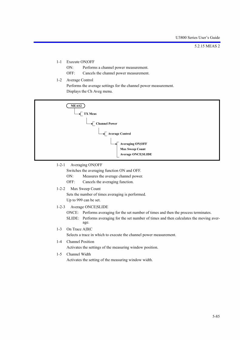
U3800 Series User’s Guide
5.2.15 MEAS 2
5-85
1-1 Execute ON|OFF
ON: Performs a channel power measurement.
OFF: Cancels the channel power measurement.
1-2 Average Control
Performs the average settings for the channel power measurement.
Displays the Ch Aveg menu.
1-2-1 Averaging ON|OFF
Switches the averaging function ON and OFF.
ON: Measures the average channel power.
OFF: Cancels the averaging function.
1-2-2 Max Sweep Count
Sets the number of times averaging is performed.
Up to 999 can be set.
1-2-3 Average ONCE|SLIDE
ONCE: Performs averaging for the set number of times and then the process terminates.
SLIDE: Performs averaging for the set number of times and then calculates the moving aver-age.
1-3 On Trace A|B|C
Selects a trace in which to execute the channel power measurement.
1-4 Channel Position
Activates the settings of the measuring window position.
1-5 Channel Width
Activates the setting of the measuring window width.
MEAS2
TX Meas
Channel Power
Average Control
Averaging ON|OFFMax Sweep CountAverage ONCE|SLIDE
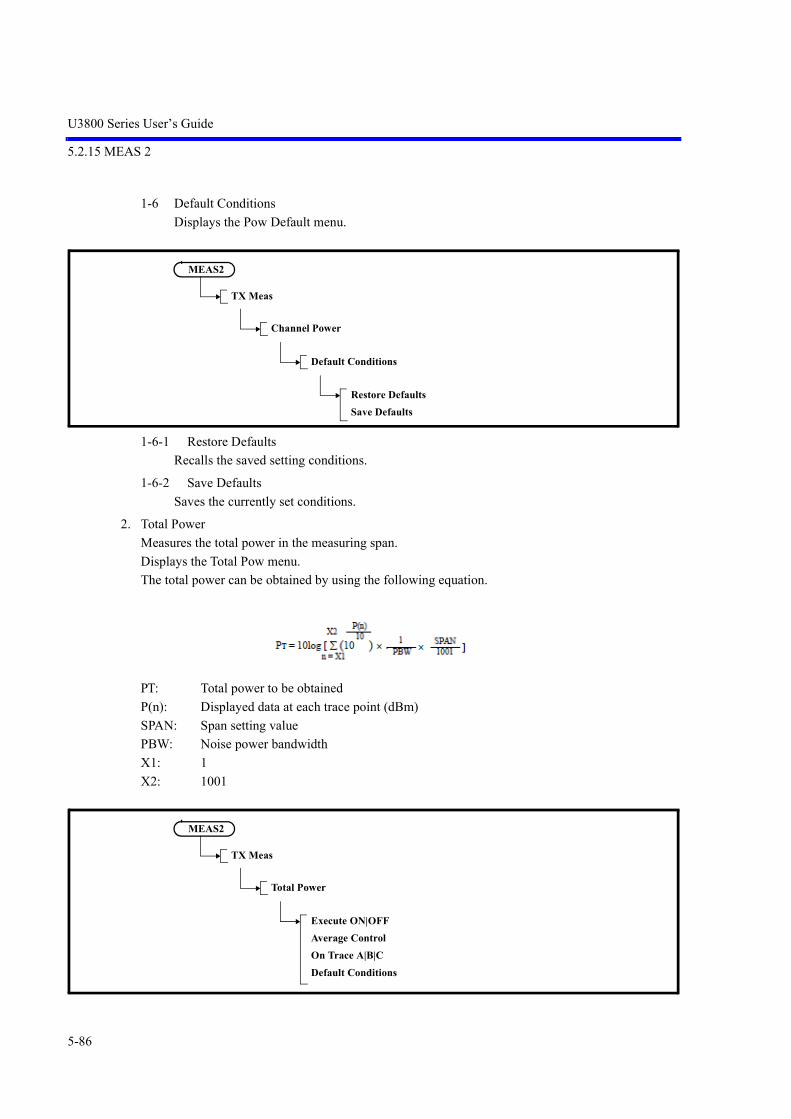
U3800 Series User’s Guide
5.2.15 MEAS 2
5-86
1-6 Default Conditions
Displays the Pow Default menu.
1-6-1 Restore Defaults
Recalls the saved setting conditions.
1-6-2 Save Defaults
Saves the currently set conditions.
2. Total Power
Measures the total power in the measuring span.
Displays the Total Pow menu.
The total power can be obtained by using the following equation.
PT: Total power to be obtained
P(n): Displayed data at each trace point (dBm)
SPAN: Span setting value
PBW: Noise power bandwidth
X1: 1
X2: 1001
MEAS2
TX Meas
Channel Power
Default Conditions
Restore DefaultsSave Defaults
MEAS2
TX Meas
Total Power
Execute ON|OFFAverage ControlOn Trace A|B|CDefault Conditions
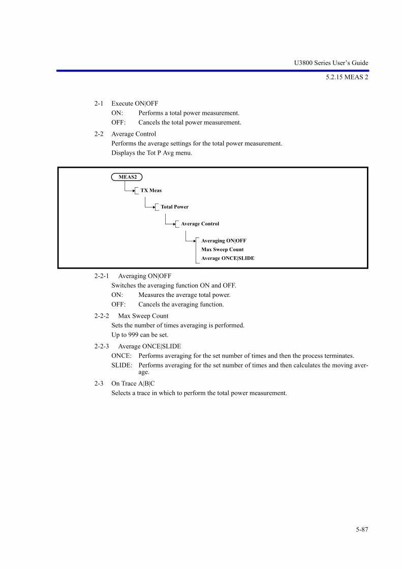
U3800 Series User’s Guide
5.2.15 MEAS 2
5-87
2-1 Execute ON|OFF
ON: Performs a total power measurement.
OFF: Cancels the total power measurement.
2-2 Average Control
Performs the average settings for the total power measurement.
Displays the Tot P Avg menu.
2-2-1 Averaging ON|OFF
Switches the averaging function ON and OFF.
ON: Measures the average total power.
OFF: Cancels the averaging function.
2-2-2 Max Sweep Count
Sets the number of times averaging is performed.
Up to 999 can be set.
2-2-3 Average ONCE|SLIDE
ONCE: Performs averaging for the set number of times and then the process terminates.
SLIDE: Performs averaging for the set number of times and then calculates the moving aver-age.
2-3 On Trace A|B|C
Selects a trace in which to perform the total power measurement.
MEAS2
TX Meas
Total Power
Average Control
Averaging ON|OFFMax Sweep CountAverage ONCE|SLIDE

U3800 Series User’s Guide
5.2.15 MEAS 2
5-88
2-4 Default Conditions
Displays the Pow Default menu.
2-4-1 Restore Defaults
Recalls the saved setting conditions.
2-4-2 Save Defaults
Saves the currently set conditions.
3. Average Power
Measures the average power in the measuring range.
Displays the Average P menu.
The average power can be obtained by using the following equation.
PAVG: Average power to be obtained
P(n): Displayed data at each trace point (dBm)
X1: 1
X2: 1001
MEAS2
TX Meas
Total Power
Default Conditions
Restore DefaultsSave Defaults
MEAS2
TX Meas
Average Power
Execute ON|OFFAverage ControlOn Trace A|B|CWindowDefault Conditions

U3800 Series User’s Guide
5.2.15 MEAS 2
5-89
3-1 Execute ON|OFF
ON: Performs an average power measurement.
OFF: Cancels the average power measurement.
3-2 Average Control
Performs the average settings for the average power measurement.
Displays the Av P Avg menu.
3-2-1 Averaging ON|OFF
Switches the averaging function ON and OFF.
ON: Sets the number of times averaging is performed and measures the average power.
OFF: Cancels the averaging function.
3-2-2 Max Sweep Count
Sets the number of times averaging is performed.
Up to 999 can be set.
3-2-3 Average ONCE|SLIDE
ONCE: Performs averaging for the set number of times and then the process terminates.
SLIDE: Performs averaging for the set number of times and then calculates the moving aver-age.
3-3 On Trace A|B|C
Selects a trace in which to execute the average power measurement.
MEAS2
TX Meas
Average Power
Average Control
Averaging ON|OFFMax Sweep CountAverage ONCE|SLIDE
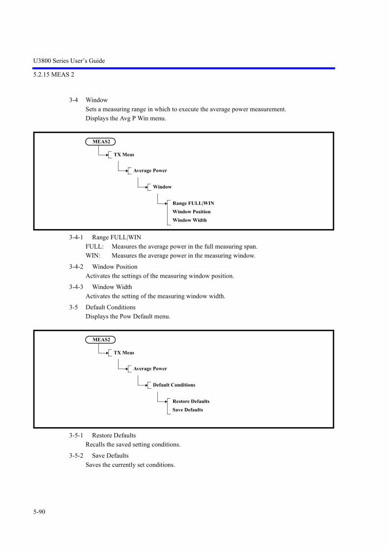
U3800 Series User’s Guide
5.2.15 MEAS 2
5-90
3-4 Window
Sets a measuring range in which to execute the average power measurement.
Displays the Avg P Win menu.
3-4-1 Range FULL|WIN
FULL: Measures the average power in the full measuring span.
WIN: Measures the average power in the measuring window.
3-4-2 Window Position
Activates the settings of the measuring window position.
3-4-3 Window Width
Activates the setting of the measuring window width.
3-5 Default Conditions
Displays the Pow Default menu.
3-5-1 Restore Defaults
Recalls the saved setting conditions.
3-5-2 Save Defaults
Saves the currently set conditions.
MEAS2
TX Meas
Average Power
Window
Range FULL|WINWindow PositionWindow Width
MEAS2
TX Meas
Average Power
Default Conditions
Restore DefaultsSave Defaults

U3800 Series User’s Guide
5.2.15 MEAS 2
5-91
4. OBW
Displays the OBW menu.
4-1 Execute ON|OFF
ON: Performs an occupied bandwidth measurement.
OFF: Cancels the occupied bandwidth measurement.
4-2 Average Control
Displays the Average Control menu.
4-2-1 Averaging ON|OFF
Switches the averaging function ON and OFF.
ON: Measures the occupied bandwidth power.
OFF: Cancels the averaging function.
4-2-2 Max Sweep Count
Sets the number of times averaging is performed.
Up to 999 can be set.
4-2-3 Average ONCE|SLIDE
ONCE: Performs averaging for the set number of times and then the process terminates.
SLIDE: Performs averaging for the set number of times and then calculates the moving aver-age.
MEAS2
TX Meas
OBW
Execute ON|OFFAverage ControlOn Trace A|B|C%OBWDefault Conditions
MEAS2
TX Meas
OBW
Average Control
Averaging ON|OFFMax Sweep CountAverage ONCE|SLIDE

U3800 Series User’s Guide
5.2.15 MEAS 2
5-92
4-3 On Trace A|B|C
Selects a trace in which to execute the occupied bandwidth measurement.
4-4 % OBW
Sets the ratio of the occupied bandwidth power to the total power in percentage.
The initial value is 99%.
4-5 Default Conditions
Displays the OBW Default menu.
4-5-1 Restore Defaults
Displays the OBW Default menu.
4-5-2 Save Defaults
Saves the currently set conditions.
5. ACP
Displays the ACP menu.
MEAS2
TX Meas
OBW
Default Conditions
Restore DefaultsSave Defaults
MEAS2
TX Meas
ACP
Execute ON|OFFAverage ControlMode FULL|CARRConfigChannel DefinitionGraph ON|OFFDefault Conditions

U3800 Series User’s Guide
5.2.15 MEAS 2
5-93
5-1 Execute ON|OFF
ON: Performs an adjacent channel leakage power measurement.
OFF: Cancels the adjacent channel leakage power measurement.
5-2 Average Control
Displays the Average Control menu.
5-2-1 Averaging ON|OFF
Switches the averaging function ON and OFF.
ON: Sets the averaging count and performs the adjacent channel leakage power measure-ment.
OFF: Cancels the averaging function.
5-2-2 Max Sweep Count
Sets the number of times averaging is performed.
Up to 999 can be set.
5-2-3 Average ONCE|SLIDE
ONCE: Performs averaging for the set number of times and then the process terminates.
SLIDE: Performs averaging for the set number of times and then calculates the moving aver-age.
5-3 Mode FULL|CARR
FULL: Calculates the adjacent channel leakage power in relation to the reference power, themeasurement of which is taken from the full bandwidth on the screen.
CARR: Calculates the adjacent channel leakage power to the reference power, the measure-ment of which is taken from the bandwidth set in Carrier Bandwidth.
MEAS2
TX Meas
ACP
Average Control
Averaging ON|OFFMax Sweep CountAverage ONCE|SLIDE

U3800 Series User’s Guide
5.2.15 MEAS 2
5-94
5-4 Config
Displays the ACP Cfg menu.
5-4-1 Carrier Bandwidth
Sets the measurement bandwidth in the channel power measurement used as the referencepower.
5-4-2 Ch Windows ON|OFF
ON: Displays the ACP channel window.
OFF: Closes the ACP channel window.
5-4-3 Nyquist Filter ON|OFF
Switches the Nyquist filter function on and off.
ON: Activates the Nyquist filter.
OFF: Cancels the Nyquist filter.
5-4-4 Nyq Symbol Rate
Set a symbol rate.
5-4-5 Nyq Roll Off Factor
Sets the roll-off factor.
5-5 Channel Definition
Displays the ACP Ch menu.
Displays the CS/BS Table dialog box.
Figure 5-30 CS/BS Table Dialog Box
MEAS2
TX Meas
ACP
Config
Carrier BandwidthCh Windows ON|OFFNyquist Filter ON|OFFNyq Symbol RateNyq Roll Off Factor

U3800 Series User’s Guide
5.2.15 MEAS 2
5-95
[Channel Space]:Sets the Offset frequency from the carrier frequency that shows the adjacent channel meas-uring position.
[Channel Bandwidth]:Sets the measurement bandwidth used in the adjacent channel leakage power measurement.
5-5-1 Insert Channel
Inserts a line on which to set adjacent channel measurement conditions at the current cursor posi-tion.
The data on the row that existed in the position before the new row was inserted is copied to thenew row.
5-5-2 Delete Channel
Deletes the measurement condition from the current cursor position.
5-5-3 Init Table
Initializes the contents of the ACP channel table.
5-5-4 Table File Recall(CSV)
Reads the CS/BS table setting from a file.
5-5-5 Table File Save(CSV)
Saves the CS/BS table setting to a file.
5-6 Graph ON|OFF
ON: Displays an ACP graph.
OFF: Hides the ACP graph.
MEAS2
TX Meas
ACP
Channel Definition
Insert ChannelDelete ChannelInit TableTable File Recall(CSV)Table File Save(CSV)

U3800 Series User’s Guide
5.2.15 MEAS 2
5-96
5-7 Default Conditions
Displays the ACP Default menu.
5-7-1 Restore Defaults
Recalls the saved setting conditions.
5-7-2 Save Defaults
Saves the currently set conditions.
6. Spectrum Emission
Displays the SEM (Spectrum Emission Mask) menu.
6-1 Execute ON|OFF
ON: Performs a spectrum emission mask measurement.
OFF: Terminates the spectrum emission mask measurement.
MEAS2
TX Meas
ACP
Default Conditions
Restore DefaultsSave Defaults
MEAS2
TX Meas
Spectrum Emission
Execute ON|OFFAverage ControlOn Trace A|B|CConfigBands DefinitionDefault Conditions

U3800 Series User’s Guide
5.2.15 MEAS 2
5-97
6-2 Average Control
Displays the SEM Avg menu.
6-2-1 Averaging ON|OFF
Switches the averaging function ON and OFF.
ON: Measures the spectrum emission mask.
OFF: Cancels the averaging function.
6-2-2 Max Sweep Count
Sets the number of times averaging is performed.
Up to 999 can be set.
6-2-3 Average ONCE|SLIDE
ONCE: Performs averaging for the set number of times and then the process terminates.
SLIDE: Performs averaging for the set number of times and then calculates the moving aver-age.
6-3 On Trace A|B|C
Selects a trace in which to execute the spectrum emission mask measurement.
MEAS2
TX Meas
Spectrum Emission
Average Control
Averaging ON|OFFMax Sweep CountAverage ONCE|SLIDE

U3800 Series User’s Guide
5.2.15 MEAS 2
5-98
6-4 Config
Displays the SEM Cfg menu.
6-4-1 Carrier Bandwidth
Sets the power conversion bandwidth for carrier signals.
6-4-2 Ref Power CHN|PEAK
Switches the reference power calculation mode between the Channel mode and the Peak Powermode.
CHN: Calculates the channel power and sets the result as the reference power for the maskmeasurement.
PEAK: Sets the Peak power value of the waveform as the reference power for the mask meas-urement.
6-4-3 Ch Windows ON|OFF
ON: Displays the SEM window.
OFF: Hides the SEM window.
6-4-4 Show Mask ON|OFF
ON: Displays the Mask line.
OFF: Hides the Mask line.
6-4-5 Nyquist Filter ON|OFF
Switches the Nyquist filter function on and off.
ON: Activates the Nyquist filter.
OFF: Cancels the Nyquist filter.
6-4-6 Nyq Symbol Rate
Set a symbol rate.
6-4-7 Nyq Roll Off Factor
Sets the roll-off factor.
MEAS2
TX Meas
Spectrum Emission
Config
Carrier BandwidthRef Power CHN|PEAKCh Windows ON|OFFShow Mask ON|OFFNyquist Filter ON|OFFNyq Symbol RateNyq Roll Off Factor

U3800 Series User’s Guide
5.2.15 MEAS 2
5-99
6-5 Bands Definition
Displays the SEM Bands menu and the SEM Table window.
6-5-1 Delete Band
Deletes a column of measurement conditions from the current cursor position.
6-5-2 Init Table
Initializes all data in the table.
Figure 5-31 SEM Table Window
[Start] Sets the offset frequency from the center frequency as the start frequency of the emis-sion mask judgment frequency band.
[Stop] Sets the offset frequency from the center frequency as the stop frequency of the emis-sion mask judgment frequency band.
[IBW] Sets the power integral bandwidth at each frequency point.(IBW: Integral bandwidth)
MEAS2
TX Meas
Spectrum Emission
Bands Definition
Delete BandInit TableTable File Recall(CSV)Table File Save(CSV)

U3800 Series User’s Guide
5.2.15 MEAS 2
5-100
[Judge] Specifies how to compare the waveform with the set mask values (absolute or relativevalues) when the mask judgment is performed.
Absolute: Compares the waveform with the mask values set in Limit Abs Start andLimit Abs Stop. If the waveform is equal to or less than the mask values,the result is Pass.
Relative: Compares the waveform with the mask values set in Limit Rel Start andLimit Rel Stop. If the waveform is equal to or less than the mask values,the result is Pass.
Abs and Rel:Compares the waveform with both the Limit Abs Start and Stop valuesand the Limit Rel Start and Stop values.If both conditions are satisfied, Pass is displayed.
Abs or Rel: Compares the waveform with both the Limit Abs Start and Stop valuesand the Limit Rel Start and Stop values. If either of the conditions is sat-isfied, Pass is displayed.
[Limit Abs Start]Sets the absolute mask value at the position of the start frequency.
[Limit Abs Stop]Sets the absolute mask value at the position of the stop frequency. A mask value at a position between the start and stop frequencies is calculated byusing the linear interpolation.
[Limit Rel Start]Sets the relative mask value at the position of the start frequency. The set mask value is used to compare with the offset value from the measured refer-ence power.
[Limit Rel Stop]Sets the relative mask value at the position of the stop frequency. A mask value at a position between the start and stop frequencies is calculated byusing the linear interpolation.
6-5-3 Table File Recall(CSV)
Reads the SEM table setting from a file.
6-5-4 Table File Save(CSV)
Saves the SEM table setting to a file.
6-6 Default Conditions
Displays the SEM Default menu.
6-6-1 Restore Defaults
Recalls the saved setting conditions.
MEAS2
TX Meas
Spectrum Emission
Default Conditions
Restore DefaultsSave Defaults

U3800 Series User’s Guide
5.2.15 MEAS 2
5-101
6-6-2 Save Defaults
Saves the currently set conditions.
7. Spurious
Displays the Spurious menu.
7-1 Execute ON|OFF
ON: Performs the spurious measurement.
OFF: Terminates the spurious measurement.
7-2 On Trace A|B|C
Selects a trace in which to execute the spurious measurement.
7-3 Bands Definition
Displays the Spr Config menu.
At the same time, the Spurious Bands setting window is displayed.
The start and stop frequencies of the spurious measurement band, the RBW, VBW, sweep time,attenuator, reference level, preamp ON or OFF, and the judgment level value used in the meas-urement can be set in the Spurious Bands setting window.
MEAS2
TX Meas
Spurious
Execute ON|OFFOn Trace A|B|CBands DefinitionResultsTable No. 1|2|3Default Conditions
MEAS2
TX Meas
Spurious
Bands Definition
Insert BandDelete BandInit TableTable File Recall(CSV)Table File Save(CSV)Table No. 1|2|3

U3800 Series User’s Guide
5.2.15 MEAS 2
5-102
Figure 5-32 Spurious Bands Setting Window
7-3-1 Insert Band
Inserts a vertical column, in which spurious measurement conditions can be set, at the currentcursor position.
The data contained in the column that existed in the position before the column was inserted iscopied as data of the new column.
7-3-2 Delete Band
Deletes a column of measurement conditions from the current cursor position.
7-3-3 Init Table
Initializes all data in the table currently being edited.
7-3-4 Table File Recall(CSV)
Reads the Spurious Bands table setting from a file.
7-3-5 Table File Save(CSV)
Saves the Spurious Bands table setting to a file.
7-3-6 Table No. 1|2|3
Sets the setting sequence table number used for the spurious measurement to 1, 2, or 3.
1: Sets table number 1.
2: Sets table number 2.
3: Sets table number 3.

U3800 Series User’s Guide
5.2.15 MEAS 2
5-103
7-4 Results
Displays the Spr Results menu.
Displays Spurious Measure Results Table.
7-4-1 Previous Band
Displays the previous screen.
7-4-2 Next Band
Displays the next screen.
7-5 Table No. 1|2|3
Sets the setting sequence table number for the spurious measurement to 1, 2, or 3.
1: Sets table number 1.
2: Sets table number 2.
3: Sets table number 3.
7-6 Default Conditions
Displays the Spr Default menu.
7-6-1 Restore Defaults
Recalls the saved setting conditions.
7-6-2 Save Defaults
Saves the currently set conditions.
MEAS2
TX Meas
Spurious
Results
Previous BandNext Band
MEAS2
TX Meas
Spurious
[Default Conditions
Restore DefaultsSave Defaults

U3800 Series User’s Guide
5.2.15 MEAS 2
5-104
5.2.15.2 MKR Meas
MEAS2
MKR Meas
Noise/HzIntermodHarmonicsFrequency Counter

U3800 Series User’s Guide
5.2.15 MEAS 2
5-105
1. Noise/Hz
Displays the Noise/Hz menu.
1-1 Noise/x Hz
Activates the setting of the noise measurement bandwidth.
The initial value is 1 Hz.
1-2 dBm/Hz ON|OFF
ON: Displays markers automatically if the marker display function is off. Sets the vertical axis unit to dBm and the marker unit to dBm/Hz.
OFF: Terminates the dBm/Hz function.
1-3 dBuV/sqrt(Hz) ON|OFF
ON: Displays markers automatically if the marker display function is off. Sets the vertical axis unit to dBµV and the marker unit to dBµV/sqrt (Hz).
OFF: Terminates the dBV/sqrt (Hz) function.
1-4 dBc/Hz ON|OFF
ON: Enables the delta marker mode automatically if the marker display function is off. Sets the delta marker unit to dBc/Hz.
OFF: Terminates the dBc/Hz function.
MEAS2
MKR Meas
Noise/Hz
Noise / x HzdBm / Hz ON|OFFdBuV / sqrt(Hz) ON|OFFdBc / Hz ON|OFF
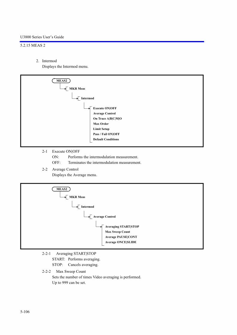
U3800 Series User’s Guide
5.2.15 MEAS 2
5-106
2. Intermod
Displays the Intermod menu.
2-1 Execute ON|OFF
ON: Performs the intermodulation measurement.
OFF: Terminates the intermodulation measurement.
2-2 Average Control
Displays the Average menu.
2-2-1 Averaging START|STOP
START: Performs averaging.
STOP: Cancels averaging.
2-2-2 Max Sweep Count
Sets the number of times Video averaging is performed.
Up to 999 can be set.
MEAS2
MKR Meas
Intermod
Execute ON|OFFAverage ControlOn Trace A|B|C|M|OMax OrderLimit SetupPass / Fail ON|OFFDefault Conditions
MEAS2
MKR Meas
Intermod
Average Control
Averaging START|STOPMax Sweep CountAverage PAUSE|CONTAverage ONCE|SLIDE

U3800 Series User’s Guide
5.2.15 MEAS 2
5-107
2-2-3 Average PAUSE|CONT
PAUSE: Pauses averaging and displays the current number of times averaging has been per-formed.
CONT: Restarts averaging from the point in which averaging was paused.
2-2-4 Average ONCE|SLIDE
ONCE: Performs averaging for the set number of times and then the process terminates.
SLIDE: Performs averaging for the set number of times and repeats averaging continuously byusing the last data.
2-3 On Trace A|B|C|M|O
Selects a trace in which to execute the intermodulation measurement.
2-4 Max Order
Sets the measurement order. The third, fifth, seventh, and ninth orders can be set.
2-5 Limit Setup
Displays the Limit Setup dialog box.
[3rd Order Limit]: Sets the limit value of the 3rd order distortion signal.
[5th Order Limit]: Sets the limit value of the 5th order distortion signal.
[7th Order Limit]: Sets the limit value of the 7th order distortion signal.
[9th Order Limit]: Sets the limit value of the 9th order distortion signal.
Figure 5-33 Limit Setup Dialog Box
2-6 Pass/Fail ON|OFF
Switches the Pass/Fail judgment based on the limit value on and off. Switches the Pass/Fail judg-ment ON and OFF due to the comparison with the value.
ON: Performs Pass/Fail judgment. If the measurement result is larger than the set limit value, it is judged as Fail.
OFF: Does not perform Pass/Fail judgment.

U3800 Series User’s Guide
5.2.15 MEAS 2
5-108
2-7 Default Conditions
Displays the IM Default menu.
2-7-1 Restore Defaults
Recalls the saved setting conditions.
2-7-2 Save Defaults
Saves the currently set conditions.
3. Harmonics
Displays the Harmonics menu.
3-1 Execute ON|OFF
ON: Executes the harmonic measurement function.
OFF: Terminates the harmonic measurement function.
MEAS2
MKR Meas
Intermod
Default Conditions
Restore DefaultsSave Defaults
MEAS2
MKR Meas
Harmonics
Execute ON|OFFAverage ControlOn Trace A|B|C|M|OHarmonic Max OrderFundamental ON|OFF

U3800 Series User’s Guide
5.2.15 MEAS 2
5-109
3-2 Average Control
Displays the Average Control menu.
3-2-1 Averaging START|STOP
START: Performs averaging.
STOP: Cancels averaging.
3-2-2 Max Sweep Count
Sets the number of times Video averaging is performed.
Up to 999 can be set.
3-2-3 Average PAUSE|CONT
PAUSE: Pauses averaging and displays the current number of times averaging has been per-formed.
CONT: Restarts averaging from the point in which averaging was paused.
3-2-4 Average ONCE|SLIDE
ONCE: Performs averaging for the set number of times and then the process terminates.
SLIDE: Performs averaging for the set number of times and repeats averaging continuously byusing the last data.
3-3 On Trace A|B|C|M|O
Selects a trace in which to execute the harmonic measurement.
3-4 Harmonic Max Order
Activates the setting of the harmonic order to be measured.
The measuring order can be set from 1 to 10.
The default value is 3.
3-5 Fundamental ON|OFF
ON: Sets the fundamental frequency. The measuring span is set in the range that includes the fundamental and set harmonicorder frequencies.
OFF: Sets the current center frequency as the fundamental frequency.
MEAS2
MKR Meas
Harmonics
Average Control
Averaging START|STOPMax Sweep CountAverage PAUSE|CONTAverage ONCE|SLIDE

U3800 Series User’s Guide
5.2.15 MEAS 2
5-110
4. Frequency Counter
Displays the Counter menu.
4-1 Execute ON|OFF
ON: Sets a frequency counter mode.
OFF: Cancels the frequency counter mode.
4-2 Counter Position
Adjusts a cursor on the measured signal.
4-3 Link to Marker ON|OFF
Corresponds the cursor at the counter position with the marker position.
If the marker position moved, then the counter position also moved.
OFF: Cancels the function.
4-4 Resolution
Displays the Cnt Res menu.
4-4-1 Resolution 1kHz
Sets the resolution of the frequency counter to 1 kHz.
4-4-2 Resolution 100Hz
Sets the resolution of the frequency counter to 100 Hz.
MEAS2
MKR Meas
Frequency Counter
Execute ON|OFFCounter PositionLink to Marker ON|OFFResolution
MEAS2
MKR Meas
Frequency Counter
Resolution
Resolution 1kHzResolution 100HzResolution 10HzResolution 1Hz
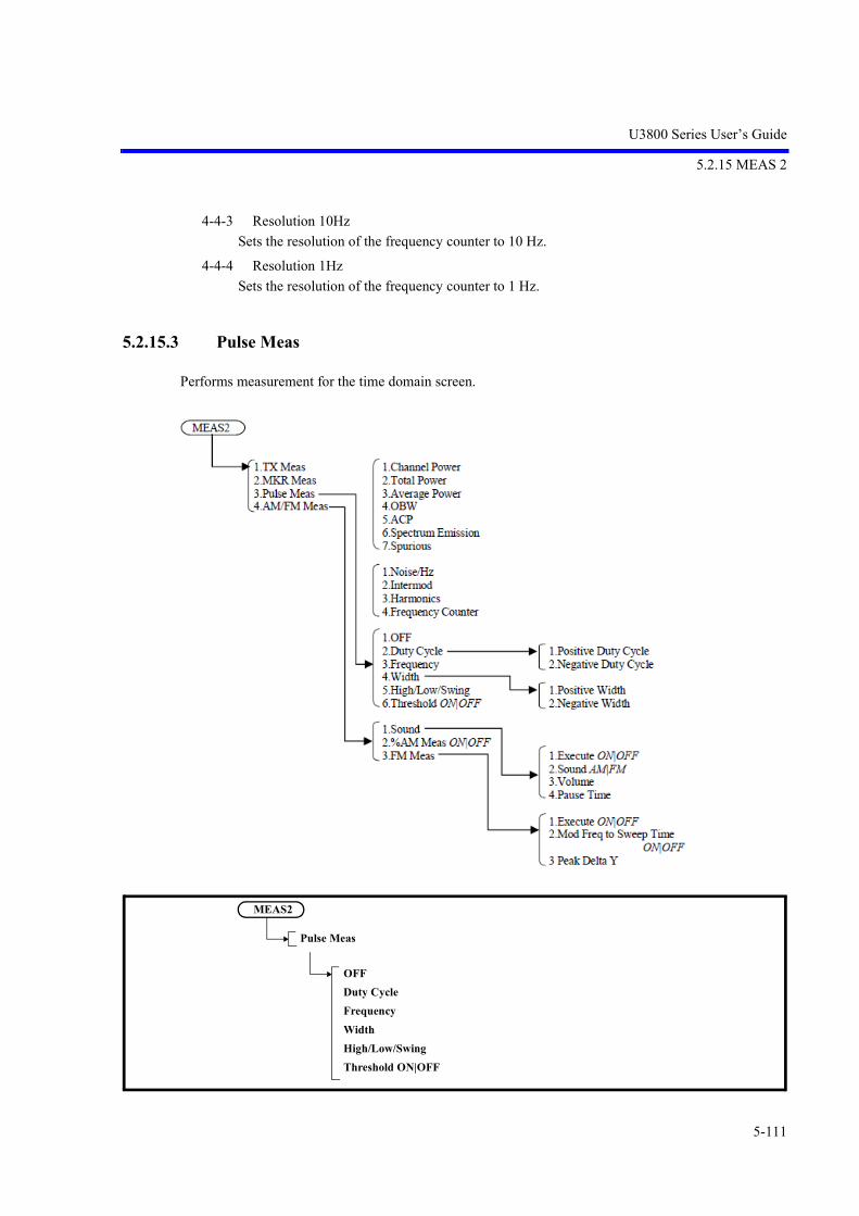
U3800 Series User’s Guide
5.2.15 MEAS 2
5-111
4-4-3 Resolution 10Hz
Sets the resolution of the frequency counter to 10 Hz.
4-4-4 Resolution 1Hz
Sets the resolution of the frequency counter to 1 Hz.
5.2.15.3 Pulse Meas
Performs measurement for the time domain screen.
MEAS2
Pulse Meas
OFFDuty CycleFrequencyWidthHigh/Low/SwingThreshold ON|OFF

U3800 Series User’s Guide
5.2.15 MEAS 2
5-112
1. OFF
Quits measuring.
2. Duty Cycle
Displays Duty Cycle measurement menus.
2-1 Positive Duty Cycle
Measures the ratio of the positive pulse width contained in the first cycle.
Positive Duty Cycle(%) = Positive pulse width/cycle * 100%
2-2 Negative Duty Cycle
Measures the ratio of the negative pulse width contained in the first cycle.
Negative Duty Cycle(%) = Negative pulse width/cycle * 100%
3. Frequency
Measures the frequency in the first cycle.
Frequency(Hz) = 1/cycle
4. Width
Displays Width measurement menus.
4-1 Positive Width
Measures the positive pulse width.
Positive Width(sec) = (Point where the waveform first crosses the threshold line from up todown) - (point where the waveform first crosses the threshold line from down to top)
4-2 Negative Width
Measures the negative pulse width.
Negative Width(sec) = (Point where the waveform first crosses the threshold line from down totop) - (point where the waveform first crosses the threshold line from top to down)
MEAS2
Pulse Meas
Duty Cycle
Positive Duty CycleNegative Duty Cycle
MEAS2
Pulse Meas
Width
Positive WidthNegative Width

U3800 Series User’s Guide
5.2.15 MEAS 2
5-113
5. High/Low/Swing
Measures the High and Low levels of trace data by using the histogram method.
When these values are displayed, obtain the amplitude (swing) value from the difference between theHigh and Low levels and display it.
The horizontal line cursor is displayed at the High and Low level positions on the measurement screen.
6. Threshold ON|OFF
Select ON/OFF for the threshold line.
This is the reference line for Measures.
5.2.15.4 AM/FM Meas
MEAS2
AM/FM Meas
Sound%AM Meas ON|OFFFM Meas

U3800 Series User’s Guide
5.2.15 MEAS 2
5-114
1. Sound
Displays the Sound menu.
Performs sound demodulation for a signal where the marker is positioned when seep ends.
1-1 Execute ON|OFF
Switches the sound demodulation function ON and OFF.
ON: Outputs the demodulated sound signal to the PHONE terminal on the front panel.
OFF: Cancels the sound demodulation function.
1-2 Sound AM/FM
Switches the demodulation mode between AM and FM.
AM: Selects the AM demodulation.
FM: Selects the FM demodulation.
1-3 Volume
Sets the demodulated sound volume.
The sound volume can be adjusted in 16 levels.
1-4 Pause Time
Sets the demodulation time.
The setting range is from 100 ms to 1000 s.
2. %AM Meas ON|OFF
Switches ON and OFF the %AM modulation factor measurement.
ON: Acquires an AM modulation factor and modulation frequency by using the peak searchfunction and displays a calculation result in percentage.
OFF: Cancels the %AM function.
MEAS2
AM/FM Meas
Sound
Execute ON|OFFSound AM|FMVolumePause Time

U3800 Series User’s Guide
5.2.15 MEAS 2
5-115
3. FM Meas
Displays the FM Meas menu.
3-1 Execute ON|OFF
Switches the FM frequency deviation measurement function on and off.
ON: Measures the frequency deviation of an FM signal.
OFF: Cancels the frequency deviation measurement function of an FM signal.
A value of Peak Delta Y is used as a condition of performing the peak search.
If setting the Mod. Freq to Sweep Time ON/OFF menu to ON and setting a modulation fre-quency in advance, a optimum sweep time is automatically set based on the modulation fre-quency and the number of display points.
If OFF is set for the Mod. Freq to Sweep Time ON/OFF menu, a sufficient sweep time must beset according to the following formula:
SWP > PT 1 / Fmod
SWP: Sweep time
PT: The number of display trace points
Fmod: Modulation frequency
(When the FM Meas function is selected, the trace detector is automatically set to the Posimode.)
3-2 Mod Freq to Sweep Time ON|OFF
Switches ON and OFF a mode, in which a sweep time is determined based on a modulation fre-quency.
ON: Sets a modulation frequency and then sets a sweep time based on the modulation fre-quency.
OFF: Cancels a mode in which a modulation frequency is set.
A value set for SWP Time AUTO/MNL is applied to a sweep time when measurement starts.
3-3 Peak Delta Y
Sets a level difference for a signal to be judged as a peak point during the peak search.
A level difference set here is used as a threshold level while searching for a peak value.
MEAS2
AM/FM Meas
FM Meas
Execute ON|OFFMod Freq to Sweep Time ON|OFFPeak Delta Y
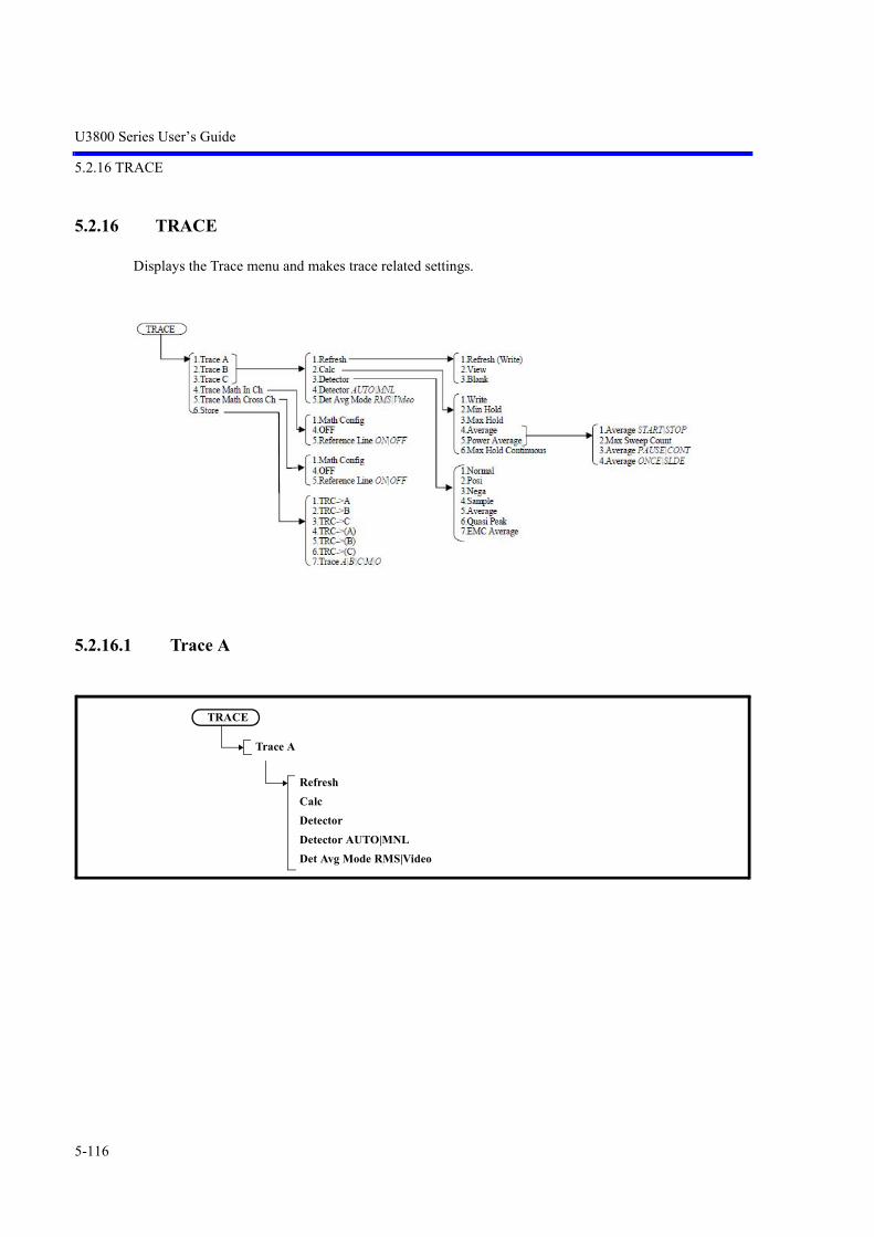
U3800 Series User’s Guide
5.2.16 TRACE
5-116
5.2.16 TRACE
Displays the Trace menu and makes trace related settings.
5.2.16.1 Trace A
TRACE
Trace A
RefreshCalcDetectorDetector AUTO|MNLDet Avg Mode RMS|Video

U3800 Series User’s Guide
5.2.16 TRACE
5-117
1. Refresh
Displays the Refresh Mode menu.
The selected setting is displayed at the bottom of the menu.
1-1 Refresh (Write)
Updates the trace data each time a sweep is performed.
1-2 View
Displays the trace data stored in the memory.
1-3 Blank
Hides the trace.
2. Calc
Displays the Calc Mode menu.
The selected setting is displayed at the bottom of the menu.
2-1 Write
Displays the waveform data acquired in the default settings.
2-2 Min Hold
Displays the minimum point value for each trace sample.
2-3 Max Hold
Displays the maximum point value for each trace sample.
TRACE
Trace A
Refresh
Refresh (Write)ViewBlank
TRACE
Trace A
Calc
WriteMin HoldMax HoldAveragePower AverageMax Hold Continuous

U3800 Series User’s Guide
5.2.16 TRACE
5-118
2-4 Average
Displays the Video Average menu.
The Video average performs averaging of the display data.
2-4-1 Average START|STOP
START: Performs averaging.
STOP: Cancels averaging.
2-4-2 Max Sweep Count
Sets the number of times Video averaging is performed.
Up to 999 can be set.
2-4-3 Average PAUSE|CONT
PAUSE: Pauses averaging and displays the current number of times averaging has been per-formed.
CONT: Restarts averaging from the point in which averaging was paused.
2-4-4 Average ONCE|SLDE
ONCE: Performs averaging for the set number of times and then the process terminates.
SLIDE: Performs averaging for the set number of times and repeats averaging continuously byusing the last data.
TRACE
Trace A
Calc
Average
Average START|STOPMax Sweep CountAverage PAUSE|CONTAverage ONCE|SLDE

U3800 Series User’s Guide
5.2.16 TRACE
5-119
2-5 Power Average
Displays the Power Average menu.
The Power Average function performs averaging of power (W) and draws waveforms.
2-5-1 Average START|STOP
START: Performs averaging.
STOP: Cancels averaging.
2-5-2 Max Sweep Count
Sets the number of times Video averaging is performed.
Up to 999 can be set.
2-5-3 Average PAUSE|CONT
PAUSE: Pauses averaging and displays the current number of times averaging has been per-formed.
CONT: Restarts averaging from the point in which averaging was paused.
2-5-4 Average ONCE|SLDE
ONCE: Performs averaging for the set number of times and then the process terminates.
SLIDE: Performs averaging for the set number of times and repeats averaging continuously byusing the last data.
2-6 Max Hold Continuous
Displays the maximum value for each trace sample.
The trace is not reset in this function which is different from the normal Calc functions.
The Max Hold operation starts at a trace point when the key is pressed.
This function can be used when the Detector mode is set to MNL.
TRACE
Trace A
Calc
Power Average
Average START|STOPMax Sweep CountAverage PAUSE|CONTAverage ONCE|SLDE

U3800 Series User’s Guide
5.2.16 TRACE
5-120
3. Detector
Displays the Detector menu.
The selected setting is displayed at the bottom of the menu.
3-1 Normal
Sets the normal detection mode to automatically detect whether the peak is positive or negativeat each trace point.
3-2 Posi
Sets the positive peak detection mode.
3-3 Nega
Sets the negative peak detection mode.
3-4 Sample
Sets the sample detection mode.
3-5 Average
Sets the average detection mode.
The average detection mode can be selected from between RMS (power average) and Video(Trace average) in the Det Avg Mode menu.
3-6 Quasi Peak
Sets the quasi peak detection mode.(OPT28)
Quasi Peak (QP) can be set when SYSTEM MODE is other than Dual Sync CH, EMC Filter isON (refer to Section 5.2.25.3, “EMC”), and RBW < 1 MHz.
According to the RBW setting, set an appropriate sweep time using the following conditions asa guide:
When RBW = 200 Hz 1 sec per 200 Hz frequency span
When RBW = 9 kHz 1 sec per 10 kHz frequency span
When RBW = 120 kHz 1 sec per 100 kHz frequency span
TRACE
Trace A
Detector
NormalPosiNegaSampleAverageQuasi PeakEMC Average
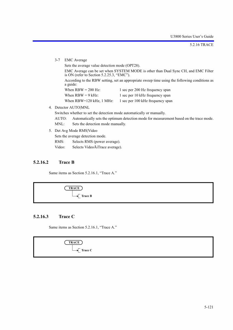
U3800 Series User’s Guide
5.2.16 TRACE
5-121
3-7 EMC Average
Sets the average value detection mode (OPT28).
EMC Average can be set when SYSTEM MODE is other than Dual Sync CH, and EMC Filteris ON (refer to Section 5.2.25.3, “EMC”).
According to the RBW setting, set an appropriate sweep time using the following conditions asa guide:
When RBW = 200 Hz: 1 sec per 200 Hz frequency span
When RBW = 9 kHz: 1 sec per 10 kHz frequency span
When RBW=120 kHz, 1 MHz: 1 sec per 100 kHz frequency span
4. Detector AUTO|MNL
Switches whether to set the detection mode automatically or manually.
AUTO: Automatically sets the optimum detection mode for measurement based on the trace mode.
MNL: Sets the detection mode manually.
5. Det Avg Mode RMS|Video
Sets the average detection mode.
RMS: Selects RMS (power average).
Video: Selects VideoÅiTrace average).
5.2.16.2 Trace B
Same items as Section 5.2.16.1, “Trace A.”
5.2.16.3 Trace C
Same items as Section 5.2.16.1, “Trace A.”
TRACE
Trace B
TRACE
Trace C

U3800 Series User’s Guide
5.2.16 TRACE
5-122
5.2.16.4 Trace Math In Ch
1. Math Config
Displays the Math Config menu.
Figure 5-34 Trace Math In Ch Dialog Box
The cursor movement of the [Write], [View], and [Blank] buttons can be switched using the step key.
Pressing the [Hz] button switches to the settings of each button.
The cursor movement of Math = [left-hand side trace] - [right-hand side trace] can also be switchedusing the step key. Operate the knob to switch the trace selection.
a. Refresh (Write)Refreshes the trace data every sweep.
b. ViewDisplays the trace data stored in memory.
c. BlankHides the trace.
d. Selecting left-hand side traceSelect Trace A, Trace B, or Trace C of the active channel by using the knob.
e. Selecting right-hand side traceSelect Trace A, Trace B, Trace C, or RefLine of the active channel by using the knob.
2. OFF
Does not perform the trace calculation.
3. Reference Line ON|OFF
ON: Displays and activates the reference line.
OFF: Hides the reference line.
TRACE
Trace Math In Ch
Math ConfigOFFReference Line ON|OFF

U3800 Series User’s Guide
5.2.16 TRACE
5-123
5.2.16.5 Trace Math Cross Ch
1. Math Config
Displays the Math Config menu.
Figure 5-35 Trace Math Cross Ch Dialog Box
The cursor movement of the [Write], [View], [Blank], [CH1-CH2], [CH2-CH1], [OFF], [Min Hold],and [Max Hold] buttons can be switched using the step key. Pressing the [Hz] button switches to thesettings of each button.
The cursor movement of Math = [left-hand side trace] - [right-hand side trace] can also be switchedusing the step key. Operate the knob to switch the trace selection.
a. Refresh (Write)Refreshes the trace data every sweep.
b. ViewDisplays the trace data stored in memory.
c. BlankHides the trace.
d. CH1-CH2Sets a subtraction in which the trace of CH2 is subtracted from the trace of CH1.
e. CH2-CH1Sets a subtraction in which the trace of CH1 is subtracted from the trace of CH2.
f. Selecting left-hand side traceSelect Trace A, Trace B, Trace C, or Trace M of the channel on the left by using the knob.
g. Selecting right-hand side traceSelect Trace A, Trace B, Trace C, or Trace M of the channel on the right by using the knob.
h. Turns off the Calc function.
i. Displays the minimum point value for each trace sample of the Trace Math result.At this point, the Trigger Sync function is set to ON.
j. Displays the maximum point value for each trace sample of the Trace Math result.At this point, the Trigger Sync function is set to ON.
TRACE
Trace Math Cross Ch
Math ConfigOFFReference Line ON|OFF
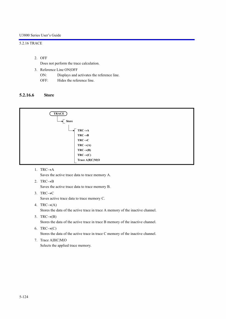
U3800 Series User’s Guide
5.2.16 TRACE
5-124
2. OFF
Does not perform the trace calculation.
3. Reference Line ON|OFF
ON: Displays and activates the reference line.
OFF: Hides the reference line.
5.2.16.6 Store
1. TRCA
Saves the active trace data to trace memory A.
2. TRCB
Saves the active trace data to trace memory B.
3. TRCC
Saves active trace data to trace memory C.
4. TRC(A)
Stores the data of the active trace in trace A memory of the inactive channel.
5. TRC(B)
Stores the data of the active trace in trace B memory of the inactive channel.
6. TRC(C)
Stores the data of the active trace in trace C memory of the inactive channel.
7. Trace A|B|C|M|O
Selects the applied trace memory.
TRACE
Store
TRCATRCBTRCCTRC(A)TRC(B)TRC(C)Trace A|B|C|M|O

U3800 Series User’s Guide
5.2.17 MKR
5-125
5.2.17 MKR
Displays the Marker menu and an active marker by pressing the MKR key.
The frequency and level on the marker are displayed in the marker area.
5.2.17.1 Select Marker
Selects the active marker and sets its position.
The marker number increases by one each time the key is pressed.
The marker number cycles from 1 to 10:
1-2-3-4-5-6-7-8-9-10-1-
The marker number decreases by one if SHIFT is pressed and then Select Marker is pressed.
MKR
Select Marker

U3800 Series User’s Guide
5.2.17 MKR
5-126
5.2.17.2 Marker ON|OFF
Activates the marker selected by Select Marker.
5.2.17.3 Marker Trace A|B|C|M|O
Moves the active marker to the selected trace.
5.2.17.4 Delta Mode
Displays the Delta Marker menu.
1. Delta ON|OFF
Switches the delta marker display function ON and OFF.
ON: Displays the delta marker and normal marker in the same position. Displays the relative values (frequency and level) to the normal marker in the marker area.
OFF: Hides the delta marker.
MKR
Marker ON|OFF
MKR
Marker Trace A|B|C|M|O
MKR
Delta Mode
Delta ON|OFFRef ObjectFlixed Mkr ON|OFF1/Delta Mkr ON|OFF
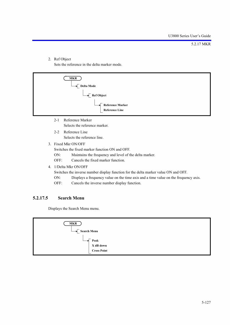
U3800 Series User’s Guide
5.2.17 MKR
5-127
2. Ref Object
Sets the reference in the delta marker mode.
2-1 Reference Marker
Selects the reference marker.
2-2 Reference Line
Selects the reference line.
3. Fixed Mkr ON/OFF
Switches the fixed marker function ON and OFF.
ON: Maintains the frequency and level of the delta marker.
OFF: Cancels the fixed marker function.
4. 1/Delta Mkr ON/OFF
Switches the inverse number display function for the delta marker value ON and OFF.
ON: Displays a frequency value on the time axis and a time value on the frequency axis.
OFF: Cancels the inverse number display function.
5.2.17.5 Search Menu
Displays the Search Menu menu.
MKR
Delta Mode
Ref Object
Reference MarkerReference Line
MKR
Search Menu
PeakX dB downCross Point

U3800 Series User’s Guide
5.2.17 MKR
5-128
1. Peak
Displays the Peak menu.
Displays the marker at the maximum level of the trace in the search range and displays the frequencyand level of the marker.
However, the frequency of the feed-through (zero carrier) is excluded.
1-1 Select Marker
Selects the active marker.
The marker number increases by one each time the key is pressed.
The marker number decreases by one if SHIFT is pressed and then Select Marker is pressed.
1-2 Next Peak
Moves the marker to the next highest peak from the current marker position in the search range.
1-3 Next Peak Right
Moves the marker to the next peak on the right (higher frequency than the current marker posi-tion) in the search range.
1-4 Next Peak Left
Moves the marker to the next peak on the left (lower frequency than the current marker position)in the search range.
MKR
Search Menu
Peak
Select MarkerNext PeakNext Peak RightNext Peak LeftConfigMin PeakNext Min PeakMin Max PeakPeak List FrequencyPeak List LevelDisplay List ON|OFF

U3800 Series User’s Guide
5.2.17 MKR
5-129
1-5 Config
Displays the Config menu.
1-5-1 Peak Delta Y
Sets a level difference for a signal to be judged as a peak point during the peak search.
This level difference is used as the threshold level for the peak point search.
1-5-2 Continuous Peak ON|OFF
Switches the continuous peak search function ON and OFF.
ON: Performs the peak search repeatedly each time a sweep is performed.
OFF: Cancels the continuous peak search function.
1-5-3 X-Search Axis
Displays the X-Search Axis menu.
MKR
Search Menu
Peak
Config
Peak Delta YContinuous Peak ON|OFFX-Search AxisY-Search Axis
MKR
Search Menu
Peak
Config
X-Search Axis
Couple to Win OFF|IN|OUTWindow PositionWindow Width

U3800 Series User’s Guide
5.2.17 MKR
5-130
1-5-3-1 Couple to Win OFF|IN|OUT
Sets a peak search range on the horizontal axis.
OFF: Sets the full range on the screen as the search range.
IN: Sets the inside of the displayed window as the search range.
OUT: Sets the outside of the displayed window as the search range.
1-5-3-2 Window Position
Sets the center position of the window defined by Couple to Win.
1-5-3-3 Window Width
Sets the window width defined by Couple to Win.
1-5-4 Y-Search Axis
Displays the Y- Search Axis menu.
1-5-4-1 Couple to DL OFF|ABV|BLW
Sets a peak search range on the vertical axis.
OFF: Searches the full range.
ABV: Sets the range above the display line as the search range.
BLW: Sets the range below the display line as the search range.
1-5-4-2 Display Line ON|OFF
ON: Displays the display line. Sets the position of the display line.
OFF: Hides the display line.
1-5-4-3 Couple to Line 1 OFF|ABV|BLW
Specifies the search range for limit line 1.
OFF: Does not specify the search range related to limit line 1.
ABV: Searches the range above limit line 1.
BLW: Searches the range below limit line 1.
MKR
Search Menu
Peak
Config
Y-Search Axis
Couple to DL OFF|ABV|BLWDisplay Line ON|OFFCouple to Line1 OFF|ABV|BLWCouple to Line2 OFF|ABV|BLWLimit Lines Edit

U3800 Series User’s Guide
5.2.17 MKR
5-131
1-5-4-4 Couple to Line 2 OFF|ABV|BLW
Specifies the search range for limit line 2.
OFF: Does not specify the search range related to limit line 2.
ABV: Searches the range above limit line 2.
BLW: Searches the range below limit line 2.
1-5-4-5 Limit Lines Edit
Displays the Limit Line menu and Limit Line table.
1-5-4-5-1 Limit Line 1|2
1: Edits limit line 1.
2: Edits limit line 2.
1-5-4-5-2 Delete Entry
Deletes the line on which the cursor is positioned in the limit line table.
1-5-4-5-3 Insert Entry
Inserts a line in the limit line table.
1-5-4-5-4 Table Edit
Edits the vertical axis limit setting.
1-5-4-5-5 Table File Recall(CSV)
Reads the vertical axis limit setting from a file.
1-5-4-5-6 Table File Save(CSV)
Saves the vertical axis limit setting to a file.
1-6 Min Peak
Moves the active marker to the minimum value of the trace in the search range.
MKR
Search Menu
Peak
Config
Y-Search Axis
Limit Lines Edit
Limit Line 1|2Delete EntryInsert EntryTable InitTable File Recall(CSV)Table File Save(CSV)

U3800 Series User’s Guide
5.2.17 MKR
5-132
1-7 Next Min Peak
Moves the marker to the next lowest peak from the current marker position in the search range.
1-8 Min Max Peak
Automatically enables the delta marker mode and moves the reference marker to the maximumvalue and the active marker to the minimum value.
1-9 Peak List Frequency
Lists peak levels and peak frequencies in order of frequency.
Figure 5-36 Peak List Frequency
1-10 Peak List Level
Lists peak levels and peak frequencies in order of peak level.
1-11 Display List ON|OFF
Switches the peak list display.
ON: Displays the list.
OFF: Hides the list.

U3800 Series User’s Guide
5.2.17 MKR
5-133
2. X dB down
Displays the X dB Down menu.
Displays markers automatically if the marker display function is off.
The trace, for which the X dB Down function is executed, is the active trace.
Set the marker on the active trace.
2-1 Execute XdBm Down
Displays the normal marker and the delta marker in the positions X dB lower than the currentpositions based on the Mode setting.
2-2 Execute XdB Left
Displays the normal marker in the position X dB lower than the current left position.
2-3 Execute XdB Right
Displays the normal marker in the position X dB lower than the current right position.
2-4 XdB Level
Activates the attenuation setting.
2-5 Display REL|ABL|ABR
Sets the method for displaying X dB Down marker data.
REL: Enables the delta marker mode when X dB Down is executed. Displays the normal marker on the right and the delta marker on the left.
ABL: Displays the marker on the left as an absolute value.
ABR: Displays the marker on the right as an absolute value.
2-6 Continuous Down ON|OFF
Switches the continuous X dB down function on and off.
ON: Performs Peak X dB down repeatedly each time a sweep is performed.
OFF: Cancels the continuous X dB down function.
2-7 Peak+XdB Down
Performs the peak search in the search range and then executes X dB Down.
MKR
Search Menu
X dB down
Execute XdBm DownExecute XdB LeftExecute XdB RightXdB LevelDisplay REL|ABL|ABRContinuous Down ON|OFFPeak+XdB Down
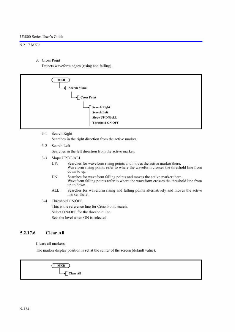
U3800 Series User’s Guide
5.2.17 MKR
5-134
3. Cross Point
Detects waveform edges (rising and falling).
3-1 Search Right
Searches in the right direction from the active marker.
3-2 Search Left
Searches in the left direction from the active marker.
3-3 Slope UP|DL|ALL
UP: Searches for waveform rising points and moves the active marker there. Waveform rising points refer to where the waveform crosses the threshold line fromdown to up.
DN: Searches for waveform falling points and moves the active marker there. Waveform falling points refer to where the waveform crosses the threshold line fromup to down.
ALL: Searches for waveform rising and falling points alternatively and moves the activemarker there.
3-4 Threshold ON|OFF
This is the reference line for Cross Point search.
Select ON/OFF for the threshold line.
Sets the level when ON is selected.
5.2.17.6 Clear All
Clears all markers.
The marker display position is set at the center of the screen (default value).
MKR
Search Menu
Cross Point
Search RightSearch LeftSlope UP|DN|ALLThreshold ON|OFF
MKR
Clear All

U3800 Series User’s Guide
5.2.17 MKR
5-135
5.2.17.7 Others HIDE|SHOW
Hides all markers except for the active marker.
5.2.17.8 Clear Others
Clears all markers except for the active marker.
5.2.17.9 Display List ON|OFF
Switches the list display of enabled markers ON and OFF.
ON: Displays a list of frequencies and levels in order of marker number.
OFF: Hides the display of marker list.
5.2.17.10 Mkr Step AUTO|MNL
Switches whether to set the step size when markers are moved by the step keys automatically or manually.
AUTO: Sets the marker step size to 1/10 of the frequency span.
MNL: Sets the step size manually.
MKR
Ohers HIDE|SHOW
MKR
Clear Others
MKR
Display List ON|OFF
MKR
Mkr Step AUTO|MNL

U3800 Series User’s Guide
5.2.17 MKR
5-136
5.2.17.11 Mode Index|Value
Selects either Index or Value as the marker position setting.
Index: Maintains the marker position at the point on the screen. If the center frequency is changed, the marker does not move and remains at the same position onthe screen.
Value: The marker position retains the frequency information. If the center frequency is changed, the marker position moves according to the frequency.
5.2.17.12 Clear All
Same as Section 5.2.17.6, “Clear All.”
5.2.17.13 Signal Track
Displays the Signal Track menu.
1. Signal Track ON|OFF
Switches the signal truck function ON and OFF.
ON: Performs the peak search for the same peak in each sweep, and sets the marker frequencyas the center frequency.
OFF: Cancels the signal truck function.
2. Y Range ON|OFF
Sets the margin when the signal track function detects the peak.
MKR
Mode Index|Value
MKR
Clear All
MKR
Signal Track
Single Track ON|OFFY Range ON|OFF

U3800 Series User’s Guide
5.2.18 PEAK
5-137
5.2.18 PEAK
Same as “1. Peak” in Section 5.2.17.5, “Search Menu.”
5.2.19 MKR
If the MKR key is pressed, active marker data such as the frequency and level can be used as the dataof other functions.
Displays the Mkr to menu.

U3800 Series User’s Guide
5.2.19 MKR
5-138
5.2.19.1 Mkr to CF
Sets the frequency at the active marker as the center frequency.
5.2.19.2 Mkr to Ref
Sets the level of the active marker as the reference level.
5.2.19.3 Peak to CF
Displays the marker at the highest peak in the search range and sets the frequency at the marker as the cen-ter frequency.
5.2.19.4 Peak to Ref
Displays the marker at the highest peak in the search range and sets the level at the marker as the referencelevel.
MKR
Mkr to CF
MKR
Mkr to Ref
MKR
Peak to CF
MKR
Peak to Ref
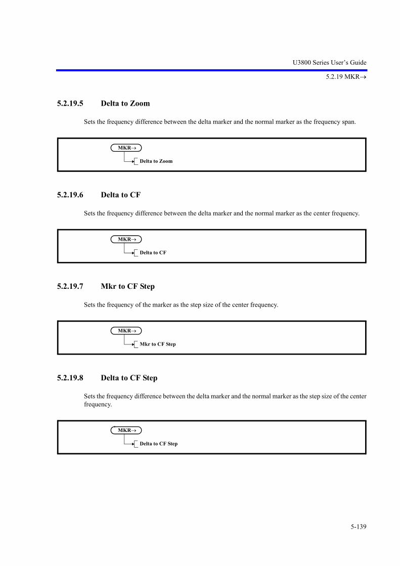
U3800 Series User’s Guide
5.2.19 MKR
5-139
5.2.19.5 Delta to Zoom
Sets the frequency difference between the delta marker and the normal marker as the frequency span.
5.2.19.6 Delta to CF
Sets the frequency difference between the delta marker and the normal marker as the center frequency.
5.2.19.7 Mkr to CF Step
Sets the frequency of the marker as the step size of the center frequency.
5.2.19.8 Delta to CF Step
Sets the frequency difference between the delta marker and the normal marker as the step size of the centerfrequency.
MKR
Delta to Zoom
MKR
Delta to CF
MKR
Mkr to CF Step
MKR
Delta to CF Step

U3800 Series User’s Guide
5.2.19 MKR
5-140
5.2.19.9 Mkr to Mkr Step
Sets the frequency of the marker as the step size of the marker.
5.2.19.10 Delta to Mkr Step
Sets the frequency difference between the delta marker and the normal marker as the step size of themarker.
5.2.19.11 Mkr to Alternate CF
Sets the frequency at the active marker for the active channel as the center frequency of the inactive chan-nel.
5.2.19.12 Peak to Alternate CF
Sets the peak frequency of the active channel as the center frequency of the inactive channel.
MKR
Mkr to Mkr Step
MKR
Delta to Mkr Step
MKR
Mkr to Alternate CF
MKR
Peak to Alternate CF

U3800 Series User’s Guide
5.2.19 MKR
5-141
5.2.19.13 Delta to Alternate Zoom
Sets the point of the delta marker (frequency) for the active channel as the start or stop frequency of theinactive channel.
5.2.19.14 Mkr to CF
NOTE: This is a menu that is displayed when the setting of MEAS1 is anything other than SPECTRUM ANAL-YSIS.
Sets the frequency at the active marker as the center frequency.
5.2.19.15 Mkr to Analysis Ofs
NOTE: This is a menu that is displayed when the setting of MEAS1 is anything other than SPECTRUM ANAL-YSIS.
Sets the time at the active marker for the active channel as Analysis Offset.
5.2.19.16 Delta to Zoom
NOTE: This is a menu that is displayed when the setting of MEAS1 is anything other than SPECTRUM ANAL-YSIS.
Sets the interval between the delta markers for the active channel as Analysis Wind, and also sets AnalysisOffset.
MKR
Delta to Alternate Zoom
MKR
Mkr to Analysis Ofs
MKR
Delta to Zoom

U3800 Series User’s Guide
5.2.19 MKR
5-142
5.2.19.17 Mkr to Vertical Pos
NOTE: This is a menu that is displayed when the setting of MEAS1 is anything other than SPECTRUM ANAL-YSIS.
Sets the vertical position value of the active marker for the active channel as the offset value of the verticalaxis when data is displayed.
5.2.19.18 Delta to V Scale/div
NOTE: This is a menu that is displayed when the setting of MEAS1 is anything other than SPECTRUM ANAL-YSIS.
Sets the vertical position value of the delta marker for the active channel as the scale (Scale/div) of thevertical axis when data is displayed.
5.2.19.19 Mkr to Mkr Step
NOTE: This is a menu that is displayed when the setting of MEAS1 is anything other than SPECTRUM ANAL-YSIS.
Sets the time at the active marker for the active channel as the step size of the marker.
MKR
Mkr to Vertical Pos
MKR
Delta to V Scale/div
MKR
Mkr to Mkr Step

U3800 Series User’s Guide
5.2.20 CURSOR
5-143
5.2.19.20 Delta to Alternate Zoom
NOTE: This is a menu that is displayed when the setting of MEAS1 is anything other than SPECTRUM ANAL-YSIS.
Sets the interval between the delta markers for the active channel as Analysis Wind of the inactive channel,and also sets Analysis Offset.
5.2.19.21 Mkr to Alternate CF
NOTE: This is a menu that is displayed when the setting of MEAS1 is anything other than SPECTRUM ANAL-YSIS.
Sets the frequency at the active marker for the active channel as the center frequency of the inactive chan-nel.
5.2.20 CURSOR
Displays the Cursor menu.
MKR
Delta to Alternate Zoom
MKR
Mkr to Alternate CF

U3800 Series User’s Guide
5.2.20 CURSOR
5-144
5.2.20.1 Execute ON|OFF
Shows or hides VertCursor.
ON: Displays VertCursor when the Dual Sync CH or Dual Async CH display mode is used.
OFF: Hides VertCursor.Also hides VertCursor when the display mode is switched to the Single CH mode.
5.2.20.2 Mode SGL|DUAL
Switches whether to display VertCursor in SINGLE mode or DUAL mode.
SGL: Displays a single VertCursor (Cursor A) for the active channel. As the measurement value of VertCursor, the absolute value of the intersection of VertCursor withthe active trace waveform is displayed along with the horizontal axis after each sweep.The difference between the 2 channels is also displayed as delta.If the X/Y domain for time domain analysis is different between the 2 channels, “*****” is dis-played.
DUAL: Displays two VertCursors (Cursors A and B) for the both channels. Cursor A is assigned to channel 1. Cursor B is assigned to channel 2.
5.2.20.3 Select A|B
Selects a cursor from between A and B when the cursor display mode is DUAL.
When the cursor is switched from A to B and vice versa, the active VertCursor and the active channel arealso switched.
CURSOR
Execute ON|OFF
CURSOR
Mode SGL|DUAL
CURSOR
Select A|B

U3800 Series User’s Guide
5.2.21 FREQUENCY
5-145
5.2.21 FREQUENCY
Displays the Frequency menu.
5.2.21.1 Center
Activates the center frequency setting.
The frequency range is displayed by the center frequency and frequency span.
5.2.21.2 Start
Activates the start frequency setting.
The frequency range is displayed by the start frequency and stop frequency.
FREQUENCY
Center
FREQUENCY
Start

U3800 Series User’s Guide
5.2.21 FREQUENCY
5-146
5.2.21.3 Stop
Activates the stop frequency setting.
The frequency range is displayed by the start frequency and stop frequency.
5.2.21.4 Frequency Offset ON|OFF
Switches the frequency offset function ON and OFF.
ON: Sets the offset value and changes only the display of the frequency by the offset value. (Displayed frequency = Set value + Offset value)
OFF: Cancels the offset function.
5.2.21.5 CF Step Size AUTO|MNL
Switches whether to set the step size when the center frequency is changed by the step keys automaticallyor manually.
AUTO: Sets the step size automatically to 1/10 of the span width.
MNL: Sets the step size manually.B
FREQUENCY
Stop
FREQUENCY
Frequency Offset ON|OFF
FREQUENCY
CF Step Size AUTO|MNL

U3800 Series User’s Guide
5.2.21 FREQUENCY
5-147
5.2.21.6 Channel Input
Displays the Channel menu.
Uses the channel code instead of the frequency for the frequency setting.
1. Freq Input Mode CALC|TABLE
Selects the channel input format.
CALC: Acquires a frequency from a channel number by using the mathematical formula.
TABLE: Acquires the frequency from the look-up table corresponding to the channel number.
2. Center CH ON|OFF
Sets a center frequency input mode for the channels.
ON: Sets the channel code input mode.
OFF: Sets the frequency input mode.
3. Start CH ON|OFF
Sets the start frequency input mode to the channel.
ON: Sets the channel code input mode.
OFF: Sets the frequency input mode.
4. Stop CH ON|OFF
Sets the stop frequency input mode to the channel.
ON: Sets the channel code input mode.
OFF: Sets the frequency input mode.
5. Start CH Offset ON|OFF
Enables the offset value of the start frequency.
ON: Offset frequency is enabled.
OFF: Offset frequency is disabled.
6. Stop CH Offset ON|OFF
Enables the offset value of the stop frequency.
ON: Offset frequency is enabled.
OFF: Offset frequency is disabled.
FREQUENCY
Channel Input
Freq Input Mode CALC|TABLECenter CH ON|OFFStart CH ON|OFFStop CH ON|OFFStart CH Offset ON|OFFStop CH Offset ON|OFFChannel Config

U3800 Series User’s Guide
5.2.21 FREQUENCY
5-148
7. Channel Config
Displays the Channels Config menu.
7-1 Edit Channel Formula
Displays the dialog box in which the mathematical formula to acquire the channel set frequencyis defined.
The following frequency is set:
Carrier frequency = Origin + CH spacing * (CH No. - CH offset)
Figure 5-37 Edit Channel Formula Dialog Box
FREQUENCY
Channel Input
Channel Config
Edit Channel FormulaEdit Channel TableFormula 1 ON|OFFFormula 2 ON|OFFFormula 3 ON|OFF
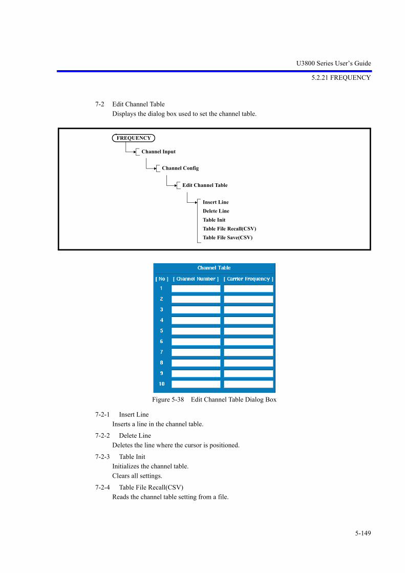
U3800 Series User’s Guide
5.2.21 FREQUENCY
5-149
7-2 Edit Channel Table
Displays the dialog box used to set the channel table.
Figure 5-38 Edit Channel Table Dialog Box
7-2-1 Insert Line
Inserts a line in the channel table.
7-2-2 Delete Line
Deletes the line where the cursor is positioned.
7-2-3 Table Init
Initializes the channel table.
Clears all settings.
7-2-4 Table File Recall(CSV)
Reads the channel table setting from a file.
FREQUENCY
Channel Input
Channel Config
Edit Channel Table
Insert LineDelete LineTable InitTable File Recall(CSV)Table File Save(CSV)

U3800 Series User’s Guide
5.2.21 FREQUENCY
5-150
7-2-5 Table File Save(CSV)
Saves the channel table setting to a file.
7-3 Formula 1 ON|OFF
Sets the mathematical formula used in the channel input mode.
This function is enabled when Freq Input Mode is set to CALC.
7-4 Formula 2 ON|OFF
Same items as “7-3 Formula 1 ON|OFF.”
7-5 Formula 3 ON|OFF
Same items as “7-3 Formula 1 ON|OFF.”
5.2.21.7 Signal Identification ON|OFF
ON: Turns on the Signal Identification function. Image signals shift to xx MHz on the screen for each sweep, but the real signals do not move.
OFF: Cancels the Signal Identification function.
5.2.21.8 Image Suppression ON|OFF
ON: Turns on the Image Suppression function. Detects image signals and deletes them from the display.
OFF: Cancels the Image Suppression function.

U3800 Series User’s Guide
5.2.22 SPAN
5-151
5.2.22 SPAN
Displays the Span menu.
5.2.22.1 Span
Activates the frequency span setting.
The frequency range is displayed by the center frequency and frequency span.
5.2.22.2 Full Span
Sets the frequency span to full span (SPAN - 8 GHz).
5.2.22.3 Zero Span
Sets zero span mode for the center frequency.
SPAN
Span
SPAN
Full Span
SPAN
Zero Span

U3800 Series User’s Guide
5.2.22 SPAN
5-152
5.2.22.4 Last Span
Returns the frequency span to the previous value.
5.2.22.5 Peak Zoom
Displays the marker at the highest peak in the targeted search range and sets the frequency of the markerto the center frequency.
At this time, the frequency span is changed to 1/10 of the currently set value.
5.2.22.6 Auto Tune ON|OFF
Searches the maximum signal level in the full band and captures the signal, then finally sets the frequencyspan to a value before AUTO TUNE starts.
The reference level is set to the peak level of the searched signal.
ON: Starts AUTO TUNE.
OFF: Stops AUTO TUNE.
SPAN
Last Span
SPAN
Peak Zoom
SPAN
Auto Tune ON|OFF
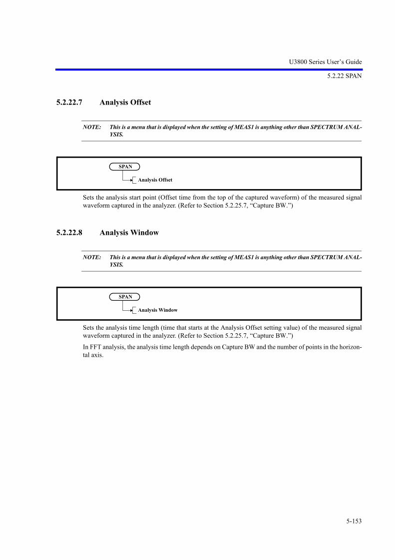
U3800 Series User’s Guide
5.2.22 SPAN
5-153
5.2.22.7 Analysis Offset
NOTE: This is a menu that is displayed when the setting of MEAS1 is anything other than SPECTRUM ANAL-YSIS.
Sets the analysis start point (Offset time from the top of the captured waveform) of the measured signalwaveform captured in the analyzer. (Refer to Section 5.2.25.7, “Capture BW.”)
5.2.22.8 Analysis Window
NOTE: This is a menu that is displayed when the setting of MEAS1 is anything other than SPECTRUM ANAL-YSIS.
Sets the analysis time length (time that starts at the Analysis Offset setting value) of the measured signalwaveform captured in the analyzer. (Refer to Section 5.2.25.7, “Capture BW.”)
In FFT analysis, the analysis time length depends on Capture BW and the number of points in the horizon-tal axis.
SPAN
Analysis Offset
SPAN
Analysis Window

U3800 Series User’s Guide
5.2.23 AMPLITUDE
5-154
5.2.23 AMPLITUDE
Displays the Level menu and enables the settings related to the amplitude display.
5.2.23.1 Ref Level
Activates the reference level setting.
5.2.23.2 ATT
Displays the Attenuation menu.
AMPLITUDE
Ref Level
AMPLITUDE
ATT
ATT AUTO|MNLMin ATTAttenuation 0dB

U3800 Series User’s Guide
5.2.23 AMPLITUDE
5-155
1. ATT AUTO|MNL
Switches whether to set the attenuator function automatically or manually.
AUTO: Automatically sets the attenuator value based on the reference level.
MNL: Sets the attenuator value manually.
2. Min ATT
Sets the minimum value of the attenuator.
This setting is enabled only when the attenuator is set manually.
3. Attenuation 0dB
Sets the attenuator to 0 dB.
Displays the confirmation window before setting.
Select OK with the step keys and press a unit key (ENTER) to confirm the entry.
5.2.23.3 dB/div
1. 10dB/div
Sets the LOG scale to 10 dB/div.
2. 5dB/div
Sets the LOG scale to 5 dB/div.
3. 2dB/div
Sets the LOG scale to 2 dB/div.
4. 1dB/div
Sets the LOG scale to 1 dB/div.
5. 0.5dB/div
Sets the LOG scale to 0.5 dB/div.
AMPLITUDE
dB/div
10dB/div5dB/div2dB/div1dB/div0.5dB/div

U3800 Series User’s Guide
5.2.23 AMPLITUDE
5-156
5.2.23.4 Vertical Scale LIN|LOG
LIN: Displays waveform data on a linear scale.
LOG: Displays waveform data on a log scale.
5.2.23.5 Units
1. dBm
Sets the display unit to dBm.
2. dBmV
Sets the display unit to dBmV.
3. dBuV
Sets the display unit to dBV.
4. dBuVemf
Sets the display unit to dVemf.
5. dBpW
Sets the display unit to dBpW.
6. Watts
Sets the display unit to Watts.
7. Volts
Sets the display unit to Volts.
AMPLITUDE
Vertical Scale LIN|LOG
AMPLITUDE
Units
dBmdBmVdBuVdBuVemfdBpWWattsVolts

U3800 Series User’s Guide
5.2.23 AMPLITUDE
5-157
5.2.23.6 Slide Screen ON|OFF
Scrolls the screen display up and down in the range of -100% to +100%.
ON: Enables the function. Enter the amount of the display scrolls by using the knob, step keys or key-pad.
OFF: Cancels the slide function.
5.2.23.7 Ref Offset ON|OFF
Switches the reference level offset function on and off.
ON: The offset level can be set in the range of -100.0 dB to +100.0 dB. The relationship among the displayed reference level, set reference level, and offset is as follows:
Displayed reference level = Set reference level + Offset
OFF: Cancels the offset function.
5.2.23.8 Input Impedance 50|75
50: Converts the level assuming that the input impedance is 50 . This setting is the standard valuethat is 50.
75: Converts the level assuming that the input impedance is 75 . The 6 dB conversion loss of the ZT-130NC, a 75/50 impedance converter, is added automati-cally.
AMPLITUDE
Slide Screen ON|OFF
AMPLITUDE
Ref Offset ON|OFF
AMPLITUDE
Input Impedance 50|75

U3800 Series User’s Guide
5.2.23 AMPLITUDE
5-158
5.2.23.9 High Sensitivity ON|OFF
Switches the high-sensitivity input function ON and OFF.
ON: Turns on the built-in preamp. Here, the preamp gain is corrected at each frequency and thereforeit does not need to be considered in level measurement.
OFF: Turns off the built-in preamp.
5.2.23.10 Correction Factor ON|OFF
ON: Corrects the display level according to the correction table.
OFF: Cancels the correction based on the correction data.
5.2.23.11 Edit Corr Factor
Displays the Corr Fact menu and the correction table.
A frequency of up to 400 GHz and a level between -100 dB and + 100 dB can be set.
1. Insert
Inserts a line in the correction table.
AMPLITUDE
High Sensitivity ON|OFF
AMPLITUDE
Correction Factor ON|OFF
AMPLITUDE
Edit Corr Fact
InsertDeleteInit TableTable File Recall(CSV)Table File Save(CSV)

U3800 Series User’s Guide
5.2.23 AMPLITUDE
5-159
2. Delete
Deletes the line on which the cursor is positioned in the correction table.
3. Init Table
Clears all settings in the correction table.
4. Table File Recall(CSV)
Reads the correction table from a file.
5. Table File Save(CSV)
Saves the correction table to a file.
5.2.23.12 Round Grid Values ON|OFF
ON: Displays the vertical scale by rounding off the Ref Level setting value to integers.
OFF: Displays the vertical scale according to the Ref Level setting value.
5.2.23.13 Ref Level
NOTE: This is a menu that is displayed when the setting of MEAS1 is anything other than SPECTRUM ANAL-YSIS, Power-Time, or Power-Freq.
Activates the reference level setting.
AMPLITUDE
Round Grid Values ON|OFF
AMPLITUDE
Ref Level

U3800 Series User’s Guide
5.2.23 AMPLITUDE
5-160
5.2.23.14 ATT
NOTE: This is a menu that is displayed when the setting of MEAS1 is anything other than SPECTRUM ANAL-YSIS, Power-Time, or Power-Freq.
Displays the Attenuation menu.
1. ATT AUTO|MNL
Switches whether to set the attenuator function automatically or manually.
AUTO: Automatically sets the attenuator value based on the reference level.
MNL: Sets the attenuator value manually.
2. Min ATT
Sets the minimum value of the attenuator.
This setting is enabled only when the attenuator is set manually.
3. Attenuation 0dB
Sets the attenuator to 0 dB.
Displays the confirmation window before setting.
Select OK with the step keys and press a unit key (ENTER) to confirm the entry.
5.2.23.15 Vertical Scale/div
NOTE: This is a menu that is displayed when the setting of MEAS1 is anything other than SPECTRUM ANAL-YSIS, Power-Time, or Power-Freq.
Sets the division of Vertical Scale.
AMPLITUDE
ATT
ATT AUTO|MNLMin ATTAttenuation 0dB
AMPLITUDE
Vertical Scale/div

U3800 Series User’s Guide
5.2.23 AMPLITUDE
5-161
5.2.23.16 Vertical Scale LIN|LOG
NOTE: This is a menu that is displayed when the setting of MEAS1 is anything other than SPECTRUM ANAL-YSIS, Power-Time, or Power-Freq.
LIN: Displays waveform data on a linear scale.
LOG: Displays waveform data on a log scale.
5.2.23.17 Units
NOTE: This is a menu that is displayed when the setting of MEAS1 is anything other than SPECTRUM ANAL-YSIS, Power-Time, or Power-Freq.
1. dBm
Sets the display unit to dBm.
2. dBmV
Sets the display unit to dBmV.
3. dBuV
Sets the display unit to dBV.
4. dBuVemf
Sets the display unit to dBVemf.
5. dBpW
Sets the display unit to dBpW.
AMPLITUDE
Vertical Scale LIN|LOG
AMPLITUDE
Units
dBmdBmVdBuVdBuVemfdBpWWattsVolts

U3800 Series User’s Guide
5.2.23 AMPLITUDE
5-162
6. Watts
Sets the display unit to Watts.
7. Volts
Sets the display unit to Volts.
5.2.23.18 Vertical Position
NOTE: This is a menu that is displayed when the setting of MEAS1 is anything other than SPECTRUM ANAL-YSIS, Power-Time, or Power-Freq.
Sets the position of Vertical Scale.
5.2.23.19 Ref Offset ON|OFF
NOTE: This is a menu that is displayed when the setting of MEAS1 is anything other than SPECTRUM ANAL-YSIS, Power-Time, or Power-Freq.
Switches the reference level offset function on and off.
ON: The offset level can be set in the range of -100.0 dB to +100.0 dB. The relationship among the displayed reference level, set reference level, and offset is as follows:
Displayed reference level = Set reference level + Offset
OFF: Cancels the offset function.
5.2.23.20 Input Impedance 50|75
NOTE: This is a menu that is displayed when the setting of MEAS1 is anything other than SPECTRUM ANAL-YSIS, Power-Time, or Power-Freq.
AMPLITUDE
Vertical Position
AMPLITUDE
Ref Offset ON|OFF

U3800 Series User’s Guide
5.2.23 AMPLITUDE
5-163
50: Converts the level assuming that the input impedance is 50 . This setting is the standard valuethat is 50.
75: Converts the level assuming that the input impedance is 75 . The 6 dB conversion loss of the ZT-130NC, a 75/50 impedance converter, is added automati-cally.
5.2.23.21 High Sensitivity ON|OFF
NOTE: This is a menu that is displayed when the setting of MEAS1 is anything other than SPECTRUM ANAL-YSIS, Power-Time, or Power-Freq.
Switches the high-sensitivity input function ON and OFF.
ON: Turns on the built-in preamp. Here, the preamp gain is corrected at each frequency and thereforeit does not need to be considered in level measurement.
OFF: Turns off the built-in preamp.
5.2.23.22 Correction Factor ON|OFF
NOTE: This is a menu that is displayed when the setting of MEAS1 is anything other than SPECTRUM ANAL-YSIS, Power-Time, or Power-Freq.
ON: Corrects the display level according to the correction table.
OFF: Cancels the correction based on the correction data.
AMPLITUDE
Input Impedance 50|75
AMPLITUDE
High Sensitivity ON|OFF
AMPLITUDE
Correction Factor ON|OFF

U3800 Series User’s Guide
5.2.23 AMPLITUDE
5-164
5.2.23.23 Edit Corr Fact
NOTE: This is a menu that is displayed when the setting of MEAS1 is anything other than SPECTRUM ANAL-YSIS, Power-Time, or Power-Freq.
Displays the Corr Factor menu and the correction table.
A frequency of up to 400 GHz and a level between -100 dB and + 100 dB can be set.
1. Insert
Inserts a line in the correction table.
2. Delete
Deletes the line on which the cursor is positioned in the correction table.
3. Init Table
Clears all settings in the correction table.
4. Table File Recall(CSV)
Reads the correction table from a file.
5. Table File Save(CSV)
Saves the correction table to a file.
AMPLITUDE
Edit Corr Fact
InsertDeleteInit TableTable File Recall(CSV)Table File Save(CSV)

U3800 Series User’s Guide
5.2.24 SWEEP
5-165
5.2.24 SWEEP
Displays the Sweep menu.
5.2.24.1 Sweep Time AUTO|MNL
Switches the sweep time between auto and manual settings.
AUTO: Automatically sets the optimum sweep time according to the frequency span, RBW, and VBWsettings.
MNL: The sweep time can be set arbitrarily.
5.2.24.2 Sweep Mode SGL|CNT
Sets the sweep mode.
SGL: Sets the SINGLE mode. The sweep starts by pressing the START/STOP key and stops after sweeping once.
CNT: Sets the CONTINUOUS mode. Repeats the sweep automatically by the next trigger signal after the sweep stops.
SWEEP
Sweep Time AUTO|MNL
SWEEP
Sweep Mode SGL|CNT

U3800 Series User’s Guide
5.2.24 SWEEP
5-166
5.2.24.3 Trigger
Displays the Trigger menu.
1. Source
Displays the Trig Source menu.
1-1 Free Run
Repeats the sweep automatically.
1-2 Video
Performs sweep in synchronization with the video signal.
1-3 External1
Synchronizes the sweep with external trigger signal 1 (EXT terminal) and then starts the sweep.
1-4 External2
Synchronizes the sweep with external trigger signal 2 (EXT terminal) and then starts the sweep.
1-5 IF
Performs sweep in synchronization with the IF signal.
1-6 Alternate Video
Selects a Video trigger signal of the other channel.
SWEEP
Trigger
SourceExt Trigger LevelLevelSlope NEG|POSDelayTrig Sync ON|OFF
SWEEP
Trigger
Source
Free RunVideoExternal1External2IFAlternate VideoAlternate IF

U3800 Series User’s Guide
5.2.24 SWEEP
5-167
1-7 Alternate IF
Selects an IF trigger signal of the other channel.
2. Ext Trigger Level
Sets the trigger signal for the external trigger signal.
3. Level
Sets the trigger level for the Video or IF trigger.
4. Slope NEG|POS
Switches the trigger slope polarity.
This setting is enabled only when the video trigger, external trigger or IF trigger is used.
NEG: The sweep starts at the falling edge of a trigger signal.
POS: The sweep starts at the rising edge of a trigger signal.
5. Delay
Sets the delay time from a trigger point.
6. Trig Sync ON|OFF
ON: When the trigger source of both channels is the same, sweep starts at the same time. When turning it ON, select the setting so that the trigger source of both channels is the same When the sweep time of each channel is different, the sweep cycle corresponds to theslower channel.
OFF: Cancels the trigger sync function. Each channel performs an asynchronous sweep.
5.2.24.4 Gated Sweep
Displays the Gated Sweep menu.
1. Gated Sweep ON|OFF
Switches the gated sweep ON and OFF.
ON: Performs the gated sweep according to the set gate conditions (gate position and width).
OFF: Cancels the gated sweep mode.
SWEEP
Gated Sweep
Gated Sweep ON|OFFSourceSlope NEG|POSGate DelayGate Width

U3800 Series User’s Guide
5.2.24 SWEEP
5-168
2. Source
Displays the Gate Source menu.
2-1 External1
Performs sweep in synchronization with external trigger signal 1.
2-2 External2
Synchronizes the sweep with external trigger signal 2 (EXT terminal) and then starts the sweep.
2-3 IF
Performs sweep in synchronization with the IF signal.
2-4 Alternate IF
Selects an IF trigger signal of the other channel.
3. Slope NEG|POS
Switches the trigger slope polarity.
NEG: The sweep starts at the falling edge of a trigger signal.
POS: The sweep starts at the rising edge of a trigger signal.
4. Gate Delay
Sets the delay time from a trigger point.
Setting range: 0 - 1sec
5. Gate Width
Sets the gate time width.
Setting range: 50sec - 1sec
Figure 5-39 Gate Width Timing Chart
SWEEP
Gated Sweep
Source
External1External2IFAlternate IF
input signal
gate signal
t1 t2 t3
t1: Gate Delay
t2: Gate Width
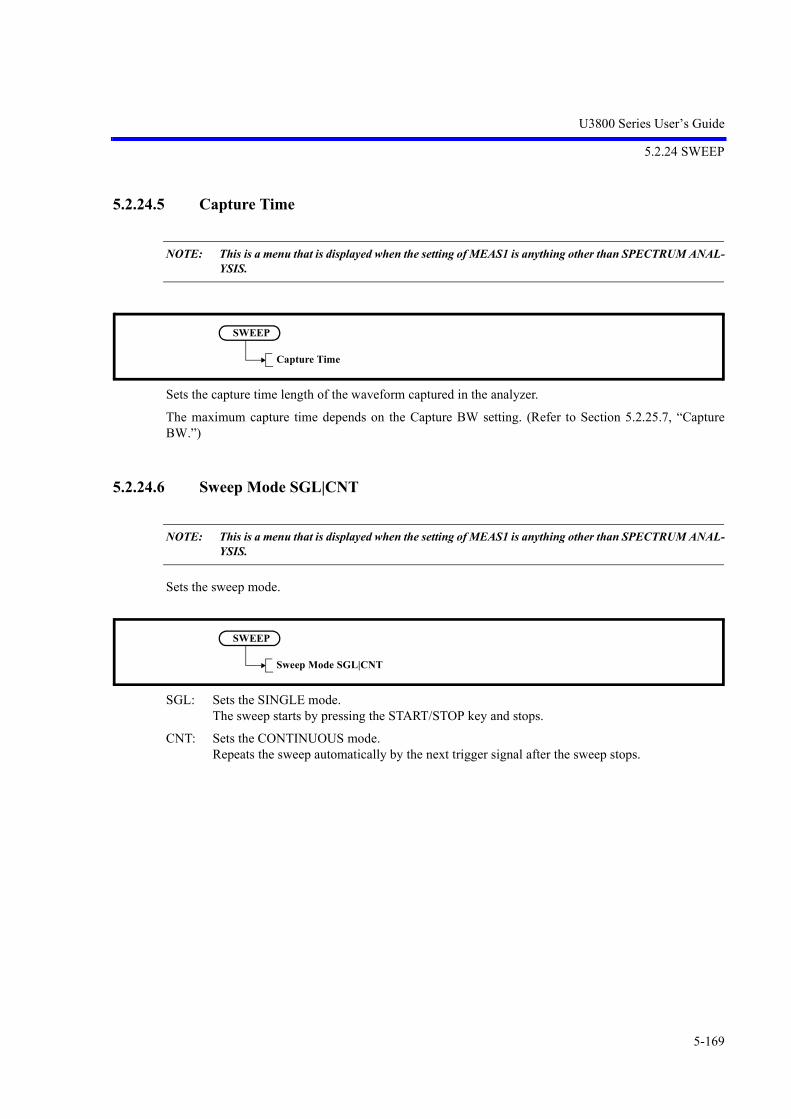
U3800 Series User’s Guide
5.2.24 SWEEP
5-169
5.2.24.5 Capture Time
NOTE: This is a menu that is displayed when the setting of MEAS1 is anything other than SPECTRUM ANAL-YSIS.
Sets the capture time length of the waveform captured in the analyzer.
The maximum capture time depends on the Capture BW setting. (Refer to Section 5.2.25.7, “CaptureBW.”)
5.2.24.6 Sweep Mode SGL|CNT
NOTE: This is a menu that is displayed when the setting of MEAS1 is anything other than SPECTRUM ANAL-YSIS.
Sets the sweep mode.
SGL: Sets the SINGLE mode. The sweep starts by pressing the START/STOP key and stops.
CNT: Sets the CONTINUOUS mode. Repeats the sweep automatically by the next trigger signal after the sweep stops.
SWEEP
Capture Time
SWEEP
Sweep Mode SGL|CNT

U3800 Series User’s Guide
5.2.24 SWEEP
5-170
5.2.24.7 Trigger
NOTE: This is a menu that is displayed when the setting of MEAS1 is anything other than SPECTRUM ANAL-YSIS.
Displays the Trigger menu.
1. Source
Displays the Trig Source menu.
1-1 Free Run
Repeats the sweep automatically.
1-2 Video
Performs sweep in synchronization with the video signal.
1-3 External1
Synchronizes the sweep with external trigger signal 1 (EXT terminal) and then starts the sweep.
1-4 External2
Synchronizes the sweep with external trigger signal 2 (EXT terminal) and then starts the sweep.
SWEEP
Trigger
SourceExt Trigger LevelLevelSlope NEG|POSDelayTrig Sync ON|OFF
SWEEP
Trigger
Source
Free RunVideoExternal1External2IFAlternate VideoAlternate IF

U3800 Series User’s Guide
5.2.24 SWEEP
5-171
1-5 IF
Performs sweep in synchronization with the IF signal.
1-6 Alternate Video
Selects a Video trigger signal of the other channel.
1-7 Alternate IF
Selects an IF trigger signal of the other channel.
2. Ext Trigger Level
Sets the trigger signal for the external trigger signal.
3. Level
Sets the trigger level for the Video or IF trigger.
4. Slope NEG|POS
Switches the trigger slope polarity.
This setting is enabled only when the video trigger, external trigger or IF trigger is used.
NEG: The sweep starts at the falling edge of a trigger signal.
POS: The sweep starts at the rising edge of a trigger signal.
5. Delay
Sets the delay time from a trigger point.
6. Trig Sync ON|OFF
ON: When the trigger source of both channels is the same, sweep starts at the same time. When turning it ON, select the setting so that the trigger source of both channels is the same When the sweep time of each channel is different, the sweep cycle corresponds to theslower channel.
OFF: Cancels the trigger sync function. Each channel performs an asynchronous sweep.

U3800 Series User’s Guide
5.2.25 BW
5-172
5.2.25 BW
Displays the Band Width menu.
5.2.25.1 RBW AUTO|MNL
Switches the RBW between auto and manual settings.
AUTO: Automatically sets the optimum RBW according to the frequency span setting.
MNL: The RBW can be set arbitrarily.
5.2.25.2 VBW AUTO|MNL
Switches the VBW between auto and manual settings.
AUTO: Automatically sets the optimum VBW according to the RBW setting.
MNL: The VBW can be set arbitrarily.
BW
RBW AUTO|MNL
BW
VBW AUTO|MNL

U3800 Series User’s Guide
5.2.25 BW
5-173
5.2.25.3 EMC
Displays the EMC menu.
1. EMC Filter ON|OFF
Cancels the EMC filter mode.
ON: Uses the EMC filter mode.
OFF: Cancels the EMC filter mode.
2. EBW Auto
Sets the resolution bandwidth (RBW) automatically according to the measurement frequency band.
3. RBW 200Hz
Sets the resolution bandwidth to 200 Hz.
4. RBW 9kHz
Sets the resolution bandwidth (RBW) to 9 kHz.
5. RBW 120kHz
Sets the resolution bandwidth (RBW) to 120 kHz.
6. RBW 1MHz
Sets the resolution bandwidth (RBW) to 1 MHz.
CAUTION:
When EMC Filter is ON, the resolution bandwidth (RBW) is displayed as follows:
(Example) For RBW 120kHz:
RBW 120kHz
RBW is underlined.
Not displayed when EMC Filter is OFF.
7. Horizontal Scale LIN|LOG
Sets LIN or LOG for Horizontal Scale.
LIN: Displays the horizontal axis in linear format.
LOG: Displays the horizontal axis in log format.
BW
EMC
EMC Filter ON|OFFRBW AutoRBW 200HzRBW 9kHzRBW 120kHzRBW 1MHzHorizontal Scale LIN|LOG

U3800 Series User’s Guide
5.2.25 BW
5-174
5.2.25.4 All Auto
Automatically sets the optimum RBW, VBW, and sweep time according to the frequency span setting.
5.2.25.5 SPAN/RBW ON|OFF
Switches the RBW versus frequency span function between the auto and manual settings.
ON: The frequency span versus RBW ratio can be changed.
OFF: The frequency span/RBW value is fixed to 100.
5.2.25.6 VBW/RBW ON|OFF
Switches the VBW versus RBW function between the auto and manual settings.
This setting is enabled only when the VBW is set to AUTO.
ON: The VBW versus RBW ratio can be changed.
OFF: The VBW/RBW value is fixed to 1.
BW
All Auto
BW
SPAN/RBW ON|OFF
BW
VBW/RBW ON|OFF

U3800 Series User’s Guide
5.2.25 BW
5-175
5.2.25.7 Capture BW
NOTE: This is a menu that is displayed when the setting of MEAS1 is anything other than SPECTRUM ANAL-YSIS.
Sets the frequency bandwidth of the waveform captured in the analyzer.
For the Capture BW setting, Capture Time is automatically limited to a value within the maximum capturetime.
NOTE: Partial FFT frequency resolution value when it is set to AUTO.
Table 5-2 Capture BW Setting Value and Partial FFT Frequency Resolution
No.Capture BW bandwidth
settingPartial FFT frequency
resolution (NOTE)
Partial FFT analysis data length
Horizontal axis of 1001 points Horizontal axis of 501 points
1 40 MHz 300 kHz 25 sec 12.5 sec
2 30 MHz 300 kHz 33 sec 16.5 sec
3 10 MHz 100 kHz 100 sec 50 sec
4 3 MHz 30 kHz 330 sec 0.165 msec
5 1 MHz 10 kHz 1 msec 0.5 msec
6 300 kHz 3 kHz 3.3 msec 1.65 msec
7 100 kHz 1 kHz 10 msec 5 msec
8 30 kHz 300 Hz 33 msec 16.5 msec
9 10 kHz 100 Hz 100 msec 50 msec
10 3 kHz 30 Hz 330 msec 165 msec
11 1 kHz 10 Hz 1 sec 500 msec
12 300 Hz 3 Hz 3.3 sec 1.65 sec
13 100 Hz 1 Hz 10 sec 5 sec
BW
Capture BW

U3800 Series User’s Guide
5.2.25 BW
5-176
5.2.25.8 RBW AUTO|MNL
NOTE: This is a menu that is displayed when the setting of MEAS1 is anything other than SPECTRUM ANAL-YSIS.
Switches the RBW between auto and manual settings.
AUTO: Automatically sets the optimum RBW according to the Capture BW setting.
MNL: The RBW can be set arbitrarily.
NOTE: The RBW is applied when the following settings are specified:Xmath: Differential or Math, and Display Type is Power-Freq or Phase-FreqMEAS1: Power-Freq
Table 5-3 Capture BW Setting Value and Capture Time Maximum Value
No. Capture BW bandwidth setting Capture Time maximum capture time
1 40 MHz 120 ms
2 30 MHz 120 ms
3 10 MHz 240 ms
4 3 MHz 600 msec
5 1 MHz 2.0 sec
6 300 kHz 6.0 sec
7 100 kHz 20 sec
8 30 kHz 60 sec
9 10 kHz 200 sec
10 3 kHz 600 sec
11 1 kHz 1000 sec
12 300 Hz 1000 sec
13 100 Hz 1000 sec
BW
RBW AUTO|MNL
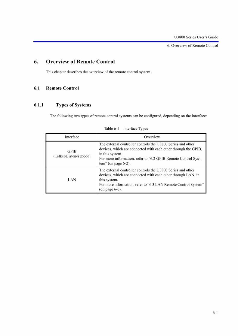
U3800 Series User’s Guide
6. Overview of Remote Control
6-1
6. Overview of Remote Control
This chapter describes the overview of the remote control system.
6.1 Remote Control
6.1.1 Types of Systems
The following two types of remote control systems can be configured, depending on the interface:
Table 6-1 Interface Types
Interface Overview
GPIB(Talker/Listener mode)
The external controller controls the U3800 Series and other devices, which are connected with each other through the GPIB, in this system.For more information, refer to “6.2 GPIB Remote Control Sys-tem” (on page 6-2).
LAN
The external controller controls the U3800 Series and other devices, which are connected with each other through LAN, in this system.For more information, refer to “6.3 LAN Remote Control System” (on page 6-6).

U3800 Series User’s Guide
6.2 GPIB Remote Control System
6-2
6.2 GPIB Remote Control System
The GPIB (General Purpose Interface Bus) that is compliant with IEEE standards 488.1-1978 and 488.2-1987 comes standard with this instrument so that remote control can be performed from the external control-ler.
The following describes how to control this instrument by using the GPIB remote control function.
6.2.1 What is the GPIB?
The GPIB (General Purpose Interface Bus) is a high performance bus that integrates computers and mea-suring instruments.
The GPIB operations are defined by IEEE standard 488.1-1978. Since the GPIB is a bus structure inter-face, the specific device can be identified by assigning a unique device address to each device. Up to 15devices can be connected to a bus in parallel. A GPIB device includes at least one of the following func-tions:
• Talker
A device that is specified to send data to the bus is called a “talker”. Only one device operates as anactive talker on a GPIB bus.
• Listener
A device that is specified to receive data from the bus is called a “listener”. Two or more active lis-tener devices exist on a GPIB bus.
• Controller
A device that specifies talkers and listeners is called a “controller”. On a GPIB bus, only one deviceoperates as an active controller. Of these controllers, a device that can control IFC and REN messagesis called the “system controller”.
Only one system controller is permitted on a GPIB bus. If there are two or more controllers on a bus,the system controller becomes the active controller at the time of system startup and the other deviceswith controller capability act as addressable devices.
To set another controller as the active controller, use Take Control (TCT) interface messages. At thistime, this controller becomes a non-active controller.
The controller controls the entire system by sending interface or device messages to each measuringinstrument. The roles of these messages are shown below.
• Interface message: Controls the GPIB bus.
• Device message: Controls the measuring instruments.

U3800 Series User’s Guide
6.2.2 Setting up the GPIB
6-3
6.2.2 Setting up the GPIB
1. GPIB connection
The standard GPIB connection is shown below. Secure the GPIB connector with two screws.
Figure 6-1 GPIB Connection
Note the following when using the GPIB interface:
• Connect the GPIB cable to the GP-IB 1 connector on the rear panel of this instrument.
• The total cable length of the GPIB cable used in one bus system should not be longer than 2 m {the number of connected devices (the GPIB controller is counted as one device)}.The total cable length should be 20 m or less.
• Up to 15 devices can be connected to one bus system.
• There is no restriction in how cables are connected. However, no more than three GPIBconnectors should be stacked on one device. If four or more GPIB connectors are stacked, thejoints of the connectors may break because excessive force is applied to them.
For example, a system consisting of five devices can use cables of up to 10 m (2 m/device 5devices = 10 m) length. Cable lengths can be allocated freely unless the total cable length exceedsthe permitted maximum length. If 10 or more devices are connected, however, some devicesshould be connected with cables less than 2 m so that the total cable length does not exceed 20 m.
• Ensure that all devices on the bus are turned on. If any device on the bus is not turned on, thesystem may not operate correctly.
• Turn off all devices on the bus before connecting or disconnecting GPIB cables.
2. GPIB address setting
GPIB addresses should be set by pressing the System key and selecting GPIB Address.

U3800 Series User’s Guide
6.2.3 GPIB Bus Functions
6-4
6.2.3 GPIB Bus Functions
6.2.3.1 GPIB Interface Functions
6.2.3.2 Responses to Interface Messages
The responses of this instrument to interface messages described in this section are defined in IEEE stan-dards 488.1-1978 and 488.2-1987.
For more information on how to send interface messages to this instrument, refer to the operation manualof the controller used.
1. Interface clear (IFC)
This message is directly sent to this instrument through a signal line.
This instrument stops the operation of the GPIB bus by using this message. Though all input/outputis stopped, the I/O buffer is not cleared (it is cleared by DCL).
2. Remote enable (REN)
This message is directly sent to this instrument through a signal line.
If this instrument is specified as a listener when this message is TRUE, it enters the remote state.
This instrument remains in this state until it receives a GTL command, REN changes to FALSE, orthe LOCAL key is pressed.
This instrument ignores all received data when it is in the local state.
When it is in the remote state, this instrument ignores all key entry except the LOCAL key.
Table 6-2 GPIB Interface Functions
Code Description
SH1 Source handshake function
AH1 Accepter handshake function
T6 Basic talker function, serial polling function, listener-specified talker cancel function
TE0 No extended talker function
L4 Basic listener function, talker-specified listener cancel function
LE0 No extended listener function
SR1 Service request function
RL1 Remote function, local function, local lockout function
PP0 No parallel polling function
DC1 Device clear function
DT0 No device trigger function
C0 No system controller function
E1 Using the open-collector bus driver

U3800 Series User’s Guide
6.2.3 GPIB Bus Functions
6-5
When it is in the local lockout state (referred to as “Local lockout (LLO)”), this instrument ignoresall key entry.
3. Serial poll enable (SPE)
When receiving this message from a controller, this instrument enters the serial polling mode.
When this instrument specified as a talker in this mode, it sends status bytes instead of ordinary mes-sages. This mode continues until this instrument receives a serial polling disable (SPD) message oran IFC message.
When this instrument is sending a service request (SRQ) message to the controller, bit6 (RQS bit) ofresponse data is set to 1 (TRUE). After transmission is completed, RQS bit is set to 0 (FALSE). Ser-vice request (SRQ) messages are directly sent through a signal line.
4. Device clear (DCL)
When receiving DCL, this instrument performs the following operations:
• Clearing the input and output buffers
• Resetting the syntax analysis, execution control, and response data generation units
• Canceling all the commands that impede the remote command to be executed next
• Canceling any commands that are waiting for other parameters
The following operations are not executed:
• Changing data that is set or stored in this instrument
• Interrupting front panel operations
• Affecting or interrupting the operations of this instrument in mid-execution
• Changing status byte excluding MAV (MAV is set to 0 as a result of clearing the output buffer)
5. Selected device clear (SDC)
Performs the same operation as DCL. However, SDC is executed only when this instrument is a lis-tener.In other cases, it is ignored.
6. Go to local (GTL)This message sets this instrument to the local state. In the local state, all front panel operations areenabled.
7. Local lockout (LLO)
This message sets this instrument to the local lockout state. When this instrument enters the remotestate from this state, all front panel operations are disabled (In the ordinary remote state, front paneloperation can be performed by pressing the LOCAL key).
In this case, this instrument can be set to the local state by any of the following two methods:
• Setting the REN message to FALSE (The local lockout state is also canceled)
• Turning off and turning on the power

U3800 Series User’s Guide
6.3 LAN Remote Control System
6-6
6.3 LAN Remote Control System
The LAN (Local Area Network) interface that is compliant with IEEE standard 802.3 is included as standardwith this instrument so that this instrument can be controlled remotely through socket communication by theexternal controller.
The controlling method using the LAN remote control function is described below.
6.3.1 Setting up the LAN
1. LAN connection
The standard LAN setup is shown below. To allow communication through the LAN between an ex-ternal controller and this instrument or other devices, connect them with 10BASE-T LAN cable andRJ45 connectors. To directly connect this instrument and an external controller with a LAN cable, usea LAN cable (cross over cable) and connect as shown in Table 6-3. To connect this instrument andother devices (excluding an external controller) with a LAN, use an external device designed to con-nect devices that has two or more LAN interfaces such as an Ethernet hub. The LAN cable used inthis case is connected as shown in Table 6-4.
Figure 6-2 LAN Setup
External controller
LAN cable
U3800 series rear panel
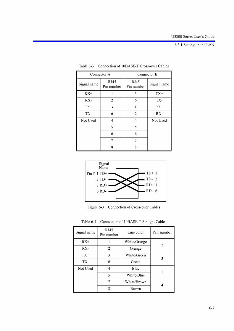
U3800 Series User’s Guide
6.3.1 Setting up the LAN
6-7
Figure 6-3 Connection of Cross-over Cables
Table 6-3 Connection of 10BASE-T Cross-over Cables
Connector A Connector B
Signal nameRJ45
Pin numberRJ45
Pin numberSignal name
RX+ 1 3 TX+
RX- 2 6 TX-
TX+ 3 1 RX+
TX- 6 2 RX-
Not Used 4 4 Not Used
5 5
6 6
7 7
8 8
Table 6-4 Connection of 10BASE-T Straight Cables
Signal nameRJ45
Pin numberLine color Pair number
RX+ 1 White/Orange2
RX- 2 Orange
TX+ 3 White/Green3
TX- 6 Green
Not Used 4 Blue1
5 White/Blue
7 White/Brown4
8 Brown
TD+ 1
TD- 2
RD+ 3
RD- 6
Pin # 1 TD+
2 TD-
3 RD+
6 RD-
Signal Name

U3800 Series User’s Guide
6.3.2 Setting the IP Address
6-8
6.3.2 Setting the IP Address
Press SYSTEM, Remote Control, and LAN IP Address.
1. Setting the IP Address Manually
Enter a check mark into the “Use the following IP address” check box.
Figure 6-4 LAN IP Address Setting
Click the Apply button and press Hz.
2. Obtaining the IP Address Automatically
Enter a check mark into the “Obtain an IP address automatically” check box.
Figure 6-5 LAN IP Address (Automatically) Setting (1)
Click the Apply button and press Hz.
After an IP address is obtained, the IP address is displayed in the window.
IP Address
Subnet Mask
Default Gateway
Set the above items.
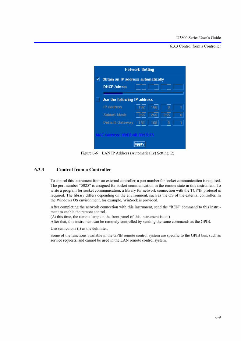
U3800 Series User’s Guide
6.3.3 Control from a Controller
6-9
Figure 6-6 LAN IP Address (Automatically) Setting (2)
6.3.3 Control from a Controller
To control this instrument from an external controller, a port number for socket communication is required.The port number “5025” is assigned for socket communication in the remote state in this instrument. Towrite a program for socket communication, a library for network connection with the TCP/IP protocol isrequired. The library differs depending on the environment, such as the OS of the external controller. Inthe Windows OS environment, for example, WinSock is provided.
After completing the network connection with this instrument, send the “REN” command to this instru-ment to enable the remote control. (At this time, the remote lamp on the front panel of this instrument is on.) After that, this instrument can be remotely controlled by sending the same commands as the GPIB.
Use semicolons (;) as the delimiter.
Some of the functions available in the GPIB remote control system are specific to the GPIB bus, such asservice requests, and cannot be used in the LAN remote control system.

U3800 Series User’s Guide
6.4 Message Exchanging Protocol
6-10
6.4 Message Exchanging Protocol
This instrument receives program messages from the controller or other devices through the GPIB bus orLAN and generates a response. Program messages include commands, queries (which are commands that askfor a response) and data.
6.4.1 Buffers
This instrument has two buffers.
1. Input buffer
This buffer temporarily stores data to analyze commands.
(1024-byte length)
The input buffer can be cleared by the following two methods:
• Turning the power on
• Executing a DCL or SDC
2. Output buffer
This buffer stores data until the data is read by the controller.
(1024-byte length)
The output buffer can be cleared by the following two methods:
• Turning the power on
• Executing a DCL or SDC
6.4.2 Message Exchange
When other controllers or devices receive messages from this instrument, the following items must beobserved:
• Generating a response in reply to a query (Refer to “Parser”).
• Generating responses in the order queries are executed (Refer to “Generating response data”).
Parser
• The parser receives command messages from the input buffer in the order queries are received, exe-cutes syntax analysis, and determines what operations are to be executed by the commands received.
Generating response data
• When the parser executes a query, this instrument generates data on the output buffer as its response (that is, a query must be sent immediately before outputting data).

U3800 Series User’s Guide
6.5 Command Syntax
6-11
6.5 Command Syntax
This chapter describes the command syntax.
6.5.1 Command Syntax
The command syntax is defined in the following format:
1. Header
Two types of header are available: the common command header and the simple header. The commoncommand header starts with an asterisk (*).The simple header is a functionally independent commandthat has no hierarchical structure.If a question mark (?) is attached immediately after a header, it becomes a query command.
2. Spaces
Spaces may be used to separate headers from data to ease readability.
3. Data
When the command requires more than one data item, list these data items by delimiting them withcommas (,). A space may be inserted before or after the comma (,). For more information on datatypes, refer to Section 6.5.2 “Data Formats.”
4. Writing more than one command
You can write multiple commands by delimiting them with semicolons (;) in one line.
DataHeader <Space (space characters)>

U3800 Series User’s Guide
6.5.2 Data Formats
6-12
6.5.2 Data Formats
This instrument uses the following data formats for the input and output data.
1. Numeric data
There are three formats for numeric data as shown below. When entering numeric values for this instrument, any format may be used. Depending on the command, a unit may be attached to the entered numeric value.
• Integer type: NR1 format
• Fixed-point type: NR2 format
• Floating-point type: NR3 format
2. Unit
Available units are listed below:
Table 6-5 Units which Can Be Used (1 of 2)
Unit Exponential Description
GZ 109 Frequency
MZ 106 Frequency
KZ 103 Frequency
HZ 100 Frequency
VOLT 100 Voltage
MV 10-3 Voltage
UV 10-6 Voltage
NV 10-9 Voltage
MW 10-3 Power
DB 100 dB description
MA 10-3 Current
SC 100 Second
MS 10-3 Second
Number[Sign]
.[Sign] Number Number
. Number
Number
Number[Sign]
E/e [Sign]

U3800 Series User’s Guide
6.5.3 Status Byte
6-13
6.5.3 Status Byte
This instrument has a layered status register structure that is compliant with IEEE standard 488.2-1987,and can send various statuses of this instrument to the controller. This section describes the behavioralmodel of status bytes and allocation of events.
1. Status Register
This instrument adopts the model of the status registers defined in IEEE standard 488.2-1987. Thestatus registers consist of the condition register, event register, and enable register.
Figure 6-7 Conditions Set for Status Byte Register
a. Condition Register
The condition register is always monitoring the status of this instrument. That is, this register alwaysretains the latest status of this instrument. However, data cannot be both written into and read fromthe condition register because the condition register retains data as internal information.
b. Event Register
The event register latches and retains statuses from the condition register (or retains changes).
Once this register is set, the setting value is kept until it is read by a query or cleared by *CLS.Data cannot be written into the event register.
US 10-6 Second
PER 100 Percentage
% 100 Percentage
Table 6-5 Units which Can Be Used (2 of 2)
Unit Exponential Description
0
1
n-1
n
0
1
n-1
n
.
.
.
.
.
0
1
n-1
n
SummaryOR
&
&
&
&
.
.
.
.
.
.
.
.
.
.
Condition register
Event register
Enable register

U3800 Series User’s Guide
6.5.3 Status Byte
6-14
c. Enable Register
The enable register specifies which bit in the event register is set as an effective status to generate asummary. The enable register is ANDed with the event register and the OR of the result is generatedas a summary. The summary is written into the status byte register.Data can be written into the enable register.
This instrument uses the following three types of status registers:
• Status byte register
• Standard event register
• Standard operation status register
The arrangement of the status register in this instrument is shown in Figure 6-8.
The details of the status register are shown in Figure 6-9.
Figure 6-8 Status Register Arrangement
UCAL
Standard event register
MAV
Standard operation status register
ESB 3 12
Output buffer
. . . . .
OPRMSS
RQS
. . . . .
Service request
Status byteregister

U3800 Series User’s Guide
6.5.3 Status Byte
6-15
Figure 6-9 Details of Status Register
2. Event Enable Register
Each event register has an enable register to determine which bit is available. The enable register setsthe corresponding bit in decimal value.
• Service request enable register setting: *SRE
• Standard event status enable register setting: *ESE
• Operation status enable register setting: OPR
3. Standard Operation Status Register
Assignment in the standard operation status register is listed below:
Standard operationstatus register
Standard event register
Status byte register
OPREVT?
dependent error

U3800 Series User’s Guide
6.5.3 Status Byte
6-16
Table 6-6 Standard Operation Status Register
Bit Function definition Description
15 Averaging 2 Set to 1 when averaging of channel 2 is complete.
14
13 Counter 2 Set to 1 when the counter measurement of channel 2 is complete.
12 Measuring 2 Set to 1 when the sequence measurement of chan-nel 2 is complete.
11 Sweeping 2 Set to 1 when the sweep of channel 2 is complete.
10
9
8 Averaging 1 Set to 1 when averaging of channel 1 is complete.
7
6
5 Counter 1 Set to 1 when the counter measurement of channel 1 is complete.
4 Measuring 1 Set to 1 when the sequence measurement of chan-nel 1 is complete.
3 Sweeping 1 Set to 1 when the sweep of channel 1 is complete.
2
1
0 Calibrating Set to 1 when correction data acquisition is com-plete.
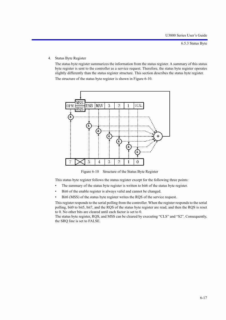
U3800 Series User’s Guide
6.5.3 Status Byte
6-17
4. Status Byte Register
The status byte register summarizes the information from the status register. A summary of this statusbyte register is sent to the controller as a service request. Therefore, the status byte register operatesslightly differently than the status register structure. This section describes the status byte register.
The structure of the status byte register is shown in Figure 6-10.
Figure 6-10 Structure of the Status Byte Register
This status byte register follows the status register except for the following three points:
• The summary of the status byte register is written to bit6 of the status byte register.
• Bit6 of the enable register is always valid and cannot be changed.
• Bit6 (MSS) of the status byte register writes the RQS of the service request.
This register responds to the serial polling from the controller. When the register responds to the serialpolling, bit0 to bit5, bit7, and the RQS of the status byte register are read, and then the RQS is resetto 0. No other bits are cleared until each factor is set to 0.The status byte register, RQS, and MSS can be cleared by executing “CLS” and “S2”. Consequently,the SRQ line is set to FALSE.

U3800 Series User’s Guide
6.5.3 Status Byte
6-18
The meaning of each bit in the status byte register is shown below:
Table 6-7 Meaning of Each Bit in Status Byte Register
Bit Functional definition Description
7 OPR A summary of the standard operation status register.
6 MSS The summary bit of the entire status data structure. RQS is set to TRUE when MSS is set to 1 in the status byte register. MSS cannot be read during serial polling but it is 1 when RQS is 1.To read the MSS, use the common command *STB?.MSS, bit0 to bit5, and bit7 of the status byte register are read by *STB?. In this case, the status byte register and MSS are not cleared.MSS is not set to 0 until all the unmasked factors in the sta-tus register structure are cleared.
5 ESB A summary of the standard event register.
4 MAV The summary bit of the output buffer.Not uses in this instrument.
3 to 1 Always 0
0 UCAL Set to 1 if a signal level error occurs because the sweep is too fast.

U3800 Series User’s Guide
6.5.3 Status Byte
6-19
5. Standard Event Register
Assignments in the standard event register are listed below:
Table 6-8 Meaning of Each Bit in Standard Event Register
Bit Functional definition Description
7 Power on Set to 1 when the power is turned on.
6 Always 0
5 Command Error Set to 1 if the parser detects a syntax error.
4 Execution Error Set to 1 if an instruction that was received as a GPIB command fails to execute for some reason (e.g., the parameter is out of range).
3 Device Dependent Error
Set to 1 if any errors except for Command Error, Exe-cution Error, and Query Error occur.
2 Query Error Set to 1 if no data exists or if data is lost when the con-troller tries to read data from this instrument.
1 Request Control Not uses in this instrument.
0 Operation Complete Not uses in this instrument.

U3800 Series User’s Guide
6.6 GPIB Remote Programming
6-20
AT Command Pages AT Command Pages
6.6 GPIB Remote Programming
This section shows the AT commands in each function:
• Command code
An asterisk “*” indicates a function that numeric or character strings data follows after the code.
Numeric data and “ON” can be omitted from [ ].
• Output format
• A comma “,” indicates that two or more data are output.
• ON or OFF indicates that 1 or 0 is output.
• Frequency is output in Hz and time is output in sec.
• Level data is output in the currently set display unit.
6.7 AT Command Index
<n>AVG*|<n>GR .................................. 6-42<n>AVG*|<n>GS ................................... 6-42<n>B ....................................................... 6-41<n>G ....................................................... 6-41<n>GC .................................................... 6-42<n>GCNT ............................................... 6-42<n>GP ..................................................... 6-42<n>GSGL ................................................ 6-42<n>MAX ................................................. 6-41<n>MIN .................................................. 6-41<n>NORM .............................................. 6-71<n>PAVG ............................................... 6-42<n>PGC .................................................. 6-42<n>PGCNT ............................................. 6-42<n>PGP ................................................... 6-42<n>PGSGL ............................................. 6-42<n>V ....................................................... 6-41<n>W ...................................................... 6-41% | PER ................................................... 6-72*CLS ....................................................... 6-68*ESE ....................................................... 6-68*ESR ....................................................... 6-68*IDN ....................................................... 6-69*OPT ....................................................... 6-69*SRE ....................................................... 6-68*STB ....................................................... 6-68AA ........................................................... 6-37ACP ......................................................... 6-58ACPCBW ................................................ 6-58
ACPLOAD .............................................. 6-58ACPNQST .............................................. 6-58ACPREF ................................................. 6-58ACPSAVE .............................................. 6-58ACPSCR ................................................. 6-58ACPTM ................................................... 6-58ACTCH ................................................... 6-29ADG ........................................................ 6-58AL ........................................................... 6-38AMMF .................................................... 6-55AMMOD ................................................. 6-55ANNOT .................................................. 6-68AR ........................................................... 6-71AS ........................................................... 6-38ASV ........................................................ 6-63ASVINTVTM ......................................... 6-63ASVLMTJDG ......................................... 6-63ASVMAXSV .......................................... 6-63ASVMODE ............................................. 6-63ASVSWPSTEP ....................................... 6-63ASVTGTCG ........................................... 6-63ASVTOTALTM ..................................... 6-63AT ........................................................... 6-37ATMIN ................................................... 6-37AUNITS .................................................. 6-37BA ........................................................... 6-38BMP ........................................................ 6-64CA ........................................................... 6-35CALCA ................................................... 6-41

U3800 Series User’s Guide
6.7 AT Command Index
6-21
CALCB ................................................... 6-41CALCC ................................................... 6-41CALCO ................................................... 6-45CAPND ................................................... 6-71CARRBS ................................................. 6-58CC ........................................................... 6-62CDB ........................................................ 6-53CF ............................................................ 6-35CFCH ...................................................... 6-36CFCHON ................................................ 6-36CHCALC1 .............................................. 6-36CHCALC2 .............................................. 6-36CHCALC3 .............................................. 6-36CHCON1 ................................................ 6-36CHCON2 ................................................ 6-36CHCON3 ................................................ 6-36CHPDIFON ............................................ 6-35CHTDEL ................................................. 6-36CHTIN .................................................... 6-36CLALL .................................................... 6-62CLATT .................................................... 6-62CLCREF ................................................. 6-62CLDREF ................................................. 6-62CLGAIN ................................................. 6-62CLPBW ................................................... 6-62CLRBW .................................................. 6-62CLSREF .................................................. 6-62CN ........................................................... 6-56CN0 ......................................................... 6-56CN1 ......................................................... 6-56CN2 ......................................................... 6-56CN3 ......................................................... 6-56CNPOS .................................................... 6-56CNPOSA ................................................. 6-56CNRES .................................................... 6-56CORS ...................................................... 6-38CORS OFF .............................................. 6-38CORS ON ............................................... 6-38COUNT ................................................... 6-56COVR ..................................................... 6-38COVR OFF ............................................. 6-38COVR ON ............................................... 6-38CP ............................................................ 6-52CP1SETTO2 ........................................... 6-29CP1TBLTO2 ........................................... 6-29CP1TO2 .................................................. 6-29CP2SETTO1 ........................................... 6-29CP2TBLTO1 ........................................... 6-29CP2TO1 .................................................. 6-29CPLCH .................................................... 6-29CR ........................................................... 6-61
CR OFF ................................................... 6-37CR ON .................................................... 6-37CRDEL ................................................... 6-37, 6-61CRIN ....................................................... 6-37, 6-61CS ............................................................ 6-35CSBSDEL ............................................... 6-58CSBSIN .................................................. 6-58CTXTSEL ............................................... 6-48DB ........................................................... 6-72DBEMF ................................................... 6-72DBM ....................................................... 6-72DBMV .................................................... 6-72DBPW ..................................................... 6-72DBUV ..................................................... 6-72DC0 ......................................................... 6-53DC1 ......................................................... 6-53DC2 ......................................................... 6-53DD ........................................................... 6-37DEL ......................................................... 6-63DET ......................................................... 6-42DETA<n> ............................................... 6-43DETAVG ................................................ 6-43DETB ...................................................... 6-42DETC ...................................................... 6-43DISP ........................................................ 6-29DLIM0 .................................................... 6-68DLIM1 .................................................... 6-68DLIM2 .................................................... 6-68DLIM5 .................................................... 6-68DLN ........................................................ 6-47DLN OFF ................................................ 6-47DLN ON ................................................. 6-47DLNFFT ................................................. 6-48DLNFRE ................................................. 6-48DLNIQ .................................................... 6-48DLNPHA ................................................ 6-48DLNPHF ................................................. 6-33DLNPWR ................................................ 6-48DS|MTSP ................................................ 6-51DUAL ..................................................... 6-29DY ........................................................... 6-52E .............................................................. 6-72EMCMEAS ............................................. 6-61EMCMEASTIM ..................................... 6-61EMCON|EMCDET ................................. 6-61ERRNO ................................................... 6-70FA ........................................................... 6-35FACH ...................................................... 6-36FACHO ................................................... 6-35FACHON ................................................ 6-36FACHOON ............................................. 6-35

U3800 Series User’s Guide
6.7 AT Command Index
6-22
FB ............................................................ 6-35FBCH ...................................................... 6-36FBCHO ................................................... 6-35FBCHON ................................................ 6-36FBCHOON ............................................. 6-35FC ............................................................ 6-62FILEFORMAT ....................................... 6-63FILEMEDIA ........................................... 6-63FINPMD ................................................. 6-35FMMEAS ................................................ 6-55FMMODF ............................................... 6-55FMMODFY ............................................ 6-55FO ........................................................... 6-35FO ON|OFF ............................................ 6-35FORM1 ................................................... 6-43FORM2 ................................................... 6-43FORM3 ................................................... 6-43FORM4 ................................................... 6-43FS ............................................................ 6-35FTPOS .................................................... 6-48FX ........................................................... 6-49GDATA .................................................. 6-64GIMAG ................................................... 6-64GTL ......................................................... 6-68GTPOS .................................................... 6-39GTSLP .................................................... 6-39GTSRC .................................................... 6-39GTSWP ................................................... 6-39GTWID ................................................... 6-39GZ ........................................................... 6-72HARM .................................................... 6-54HARMNUM ........................................... 6-54HCOPY ................................................... 6-67HRMFND ............................................... 6-54HRMFND OFF ....................................... 6-54HRMFND ON ......................................... 6-54HS ........................................................... 6-37HSCALE ................................................. 6-61HZ ........................................................... 6-72ID ............................................................ 6-69IMGSP .................................................... 6-36IMLOAD ................................................ 6-54IMLS3 ..................................................... 6-53IMLS5 ..................................................... 6-53IMLS7 ..................................................... 6-54IMLS9 ..................................................... 6-54IMM ........................................................ 6-53IMMDF ................................................... 6-53IMMREF ................................................. 6-53IMMRES ................................................. 6-53IMODR ................................................... 6-53
IMPFC .................................................... 6-54IMSAVE ................................................. 6-54IP|*RST ................................................... 6-67IQBSV .................................................... 6-63KZ ........................................................... 6-72LARNG ................................................... 6-47LBRNG ................................................... 6-47LIMAPOS ............................................... 6-46LIMAS .................................................... 6-46LIMASFT ............................................... 6-46LIMPOS .................................................. 6-46LIMS ....................................................... 6-46LIMSF ..................................................... 6-46LIMST .................................................... 6-46LL1 .......................................................... 6-37LLO ......................................................... 6-68LMTA ..................................................... 6-46LMTADELF ........................................... 6-46LMTADELT ........................................... 6-46LMTAINF ............................................... 6-46LMTAINT .............................................. 6-46LMTB ..................................................... 6-46LMTBDELF ........................................... 6-47LMTBDELT ........................................... 6-47LMTBINF ............................................... 6-47LMTBINT ............................................... 6-47LMTMRGN ............................................ 6-61LOF ......................................................... 6-67LON ........................................................ 6-67LTSP|LS .................................................. 6-35M0|MKCS ............................................... 6-51M1|MTCS ............................................... 6-51M2|MKMKS ........................................... 6-51M3|MTMKS ........................................... 6-51MC|MKCF .............................................. 6-51MDF2 ...................................................... 6-49MDL2 ...................................................... 6-49MEASFUNC ........................................... 6-29MF<n> .................................................... 6-49MFL ........................................................ 6-49MFL<n> .................................................. 6-49MFLC ...................................................... 6-49MFLC<n> ............................................... 6-49MFR ........................................................ 6-49MIS ......................................................... 6-52MK .......................................................... 6-49MKACF .................................................. 6-51MKAO .................................................... 6-51MKBW .................................................... 6-53MKD ....................................................... 6-49MKDD .................................................... 6-50

U3800 Series User’s Guide
6.7 AT Command Index
6-23
MKLST ................................................... 6-50MKMODE .............................................. 6-50MKROBJ ................................................ 6-49MKRSEL ................................................ 6-49MKSPOS ................................................ 6-52MKSWID ................................................ 6-52MKSX ..................................................... 6-52MKSYDL ................................................ 6-52MKSYLA ................................................ 6-52MKSYLB ................................................ 6-52MKTRACE ............................................. 6-50MKVP ..................................................... 6-51ML .......................................................... 6-49ML<n> .................................................... 6-49MLN ........................................................ 6-49MLN<n> ................................................. 6-49MLR ........................................................ 6-49MLSFL .................................................... 6-50MLTOFF ................................................. 6-49MLTSCR ................................................ 6-47MMS ....................................................... 6-52MNRF ..................................................... 6-68MO|MKOFF ........................................... 6-49MPA ........................................................ 6-50MPM ....................................................... 6-50MR|MKRL .............................................. 6-51MS | MSEC ............................................. 6-72MTAAW ................................................. 6-51MTASP ................................................... 6-51MTAW .................................................... 6-51MTB ........................................................ 6-44MTCF ...................................................... 6-51MTDIV ................................................... 6-51MTV ........................................................ 6-44MTW ....................................................... 6-44MV .......................................................... 6-72MW ......................................................... 6-72MZ .......................................................... 6-72NI ............................................................ 6-53NIC .......................................................... 6-53NIF .......................................................... 6-53NIM ......................................................... 6-53NION ...................................................... 6-53NIRES ..................................................... 6-53NIU ......................................................... 6-53NORM .................................................... 6-71NSEC ...................................................... 6-72NV ........................................................... 6-72NXL ........................................................ 6-52NXM ....................................................... 6-52NXP ........................................................ 6-52
NXR ........................................................ 6-52OB ........................................................... 6-44OBW ....................................................... 6-57OBWLOAD ............................................ 6-58OBWON ................................................. 6-57OBWPER ................................................ 6-57OBWSAVE ............................................. 6-58OBWTM ................................................. 6-58OHM ....................................................... 6-37OPR ......................................................... 6-68OPREVT ................................................. 6-68OPT20 ..................................................... 6-69OPT28 ..................................................... 6-69OPT76 ..................................................... 6-69OPT77 ..................................................... 6-69OV ........................................................... 6-44OW .......................................................... 6-44PFC ......................................................... 6-46PFJ?|OPF? ............................................... 6-46PKACF .................................................... 6-51PKCF ...................................................... 6-51PKRL ...................................................... 6-51PKZOOM ................................................ 6-36PLS FREQ .............................................. 6-52PLS LEVEL ............................................ 6-52PMEASAVG .......................................... 6-56PMEASAVGONCE ................................ 6-56PMEASMODE ....................................... 6-56PMEASOFF ............................................ 6-56PMEASTM ............................................. 6-56PMEASTRACE ...................................... 6-57PNG ........................................................ 6-64PPM ........................................................ 6-72PS ............................................................ 6-52PSXDB .................................................... 6-53PU ........................................................... 6-55PWAVG .................................................. 6-57PWAVGLOAD ....................................... 6-57PWAVGON ............................................ 6-57PWAVGRANGE .................................... 6-57PWAVGSAVE ....................................... 6-57PWAVGTM ............................................ 6-57PWCH ..................................................... 6-57PWCHLOAD .......................................... 6-57PWCHON ............................................... 6-57PWCHPSD .............................................. 6-57PWCHSAVE .......................................... 6-57PWCHTM ............................................... 6-57PWTOTAL ............................................. 6-57PWTOTALON ........................................ 6-57PWTOTALPSD ...................................... 6-57

U3800 Series User’s Guide
6.7 AT Command Index
6-24
PWTOTALTM ....................................... 6-57PWTOTLOAD ........................................ 6-57PWTOTSAVE ........................................ 6-57QP0 ......................................................... 6-61QP1 ......................................................... 6-61QP2 ......................................................... 6-61QP3 ......................................................... 6-61QPAUTO|QA .......................................... 6-61QRC ........................................................ 6-63QSV ........................................................ 6-63RB ........................................................... 6-38RC ........................................................... 6-63RCSET .................................................... 6-63RCTBL .................................................... 6-64RCTRC ................................................... 6-63RCVCORR ............................................. 6-64RECALCON ........................................... 6-31, 6-32,
6-34REDLT .................................................... 6-50REN ........................................................ 6-68RENAME ................................................ 6-63RF ............................................................ 6-67RFACT .................................................... 6-58RFC ......................................................... 6-67RFE ......................................................... 6-67RFI .......................................................... 6-67RFX ......................................................... 6-67RL ........................................................... 6-37RLN ........................................................ 6-47RLN OFF ................................................ 6-47RLN ON .................................................. 6-47RLNFFT .................................................. 6-48RLNFRE ................................................. 6-48RLNIQ .................................................... 6-48RLNPHA ................................................ 6-48RLNPHF ................................................. 6-33RLNPWR ................................................ 6-48RO ........................................................... 6-37RO ON|OFF ............................................ 6-37RX ........................................................... 6-71S0 ............................................................ 6-68S1 ............................................................ 6-68S2 ............................................................ 6-68SAM ........................................................ 6-55SC ............................................................ 6-72SCRF ....................................................... 6-68SDV ........................................................ 6-55SEM ........................................................ 6-59SEMCBW ............................................... 6-58SEMLOAD ............................................. 6-58SEMNQST .............................................. 6-58
SEMON .................................................. 6-58SEMRFCALC ......................................... 6-58SEMRFPOW .......................................... 6-59SEMSAVE .............................................. 6-58SEMTDEL .............................................. 6-59SEMTIN .................................................. 6-59SEMTM .................................................. 6-58SETDATE ............................................... 6-69SETTIME ................................................ 6-69SFM ........................................................ 6-55SG ........................................................... 6-50SGY ........................................................ 6-50SGY OFF ................................................ 6-50SGY ON .................................................. 6-50SIGID ...................................................... 6-36SOF ......................................................... 6-55SON ........................................................ 6-55SP ............................................................ 6-35SPRFDEL ............................................... 6-60SPRIN|SPRFIN ....................................... 6-59SPRTBL .................................................. 6-59SPURI ..................................................... 6-59SQL ......................................................... 6-33SQLLVL ................................................. 6-33STORE .................................................... 6-42SUPIP ...................................................... 6-67SV ........................................................... 6-63SW|ST ..................................................... 6-38SWM ....................................................... 6-38SWPABORT ........................................... 6-39SWPCNT ................................................ 6-41SYMRT ................................................... 6-58SYNCTRIG ............................................ 6-40SYSMODE ............................................. 6-29T<n> ....................................................... 6-41TAA ........................................................ 6-43TAB ........................................................ 6-43TAC ........................................................ 6-43TAM ........................................................ 6-44TAO ........................................................ 6-44TBA ........................................................ 6-43TBA1 ...................................................... 6-43TBA2 ...................................................... 6-43TBB ......................................................... 6-43TBB1 ....................................................... 6-43TBB2 ....................................................... 6-43TBC ......................................................... 6-43TBC1 ....................................................... 6-43TBC2 ....................................................... 6-43TBLRC .................................................... 6-64TBLSV .................................................... 6-64

U3800 Series User’s Guide
6.7 AT Command Index
6-25
TBM ........................................................ 6-44TBM1 ...................................................... 6-44TBM2 ...................................................... 6-44TBO ........................................................ 6-44TBO1 ...................................................... 6-45TBO2 ...................................................... 6-45TG ........................................................... 6-71TGDLTRLN ........................................... 6-71TGF ......................................................... 6-71TGL ......................................................... 6-71TGLO ...................................................... 6-71TGLO ON|OFF ....................................... 6-71TGO ........................................................ 6-71TGO ON|OFF ......................................... 6-71THRESH ................................................. 6-33THRFFT .................................................. 6-33THRFRE ................................................. 6-33THRIQ .................................................... 6-33THRPHA ................................................ 6-33THRPHF ................................................. 6-33THRPWR ................................................ 6-33TN ........................................................... 6-36TPL|TP .................................................... 6-42TPS|TP .................................................... 6-42TRACESEL ............................................ 6-43TRGDLY ................................................ 6-40TRGLVL ................................................. 6-40TRGOUTCH ........................................... 6-40TRGOUTTHR ........................................ 6-40TRGSLP .................................................. 6-40TRGSRC ................................................. 6-40TRGTTL2LVL ....................................... 6-40TRGTTLLVL ......................................... 6-40TRSUB .................................................... 6-44TRXSUB12 ............................................. 6-45TRXSUB21 ............................................. 6-45TRXSUBOFF ......................................... 6-44TST ......................................................... 6-69, 6-70US | USEC .............................................. 6-72UV ........................................................... 6-72V | VOLT ................................................ 6-72VA ........................................................... 6-38VB ........................................................... 6-38VCDEFCND ........................................... 6-30, 6-32,
6-34VCFA ...................................................... 6-30, 6-31,
6-34, 6-77VCFB ...................................................... 6-30, 6-31,
6-34, 6-77VCFSEXTABORT ................................. 6-77VCFSEXTEXE ....................................... 6-77
VCFSEXTFINISH .................................. 6-77VCFSEXTIDX ........................................ 6-77VCFSEXTINIT ....................................... 6-77, 6-78VCFSEXTSTPSZ ................................... 6-77VCFSTEP ............................................... 6-30, 6-31,
6-34, 6-77VCINBEXE ............................................ 6-30, 6-32,
6-34VCINBEXTABORT ............................... 6-78VCINBEXTEXE .................................... 6-78VCINBEXTFINISH ............................... 6-78VCINBEXTFO ....................................... 6-78VCINBEXTIDX ..................................... 6-78VCINBEXTINIT .................................... 6-78VCINBEXTSTPSZ ................................. 6-78VCORR ................................................... 6-30, 6-31,
6-34VCSIGLVLADJ ..................................... 6-30, 6-32,
6-34VCSIGSRC ............................................. 6-30, 6-32,
6-34VCSMPLEXE ......................................... 6-30, 6-31,
6-34VCSPANEXE ......................................... 6-30, 6-31,
6-34VCSTAT ................................................. 6-30, 6-32,
6-34VPOSPHF ............................................... 6-33VS ........................................................... 6-37VSCLPHF ............................................... 6-33VSWR ..................................................... 6-71VSWRLOSS ........................................... 6-71VSWRON ............................................... 6-71W | WATT .............................................. 6-72WDOSWP ............................................... 6-47WDX ....................................................... 6-47WLX ....................................................... 6-47WP .......................................................... 6-63XAOFS ................................................... 6-31, 6-34XATIM ................................................... 6-31, 6-33XCAPBW ............................................... 6-30XCAPTBW ............................................. 6-31, 6-32XCAPTIM .............................................. 6-30, 6-32XCAPTTIM ............................................ 6-31XCH1MAG ............................................. 6-32XCH1PHA .............................................. 6-32XCH1TIM ............................................... 6-32XCH2MAG ............................................. 6-32XCH2PHA .............................................. 6-33XCH2TIM ............................................... 6-33XDB ........................................................ 6-53

U3800 Series User’s Guide
6.7 AT Command Index
6-26
XDIFFON ............................................... 6-31XDISP ..................................................... 6-31, 6-33XDL ........................................................ 6-53XDOM .................................................... 6-33XDR ........................................................ 6-53XLHSCH ................................................ 6-33XMATHON ............................................ 6-32XMATHOP ............................................. 6-33XPRPDAOFS ......................................... 6-30XPRPDATIM ......................................... 6-30XPRPDON .............................................. 6-30XREFCH ................................................. 6-30, 6-31XRHSCH ................................................ 6-33XSCRSEL ............................................... 6-31, 6-32ZAT ......................................................... 6-37ZMPOS ................................................... 6-48ZMWID .................................................. 6-48ZS ............................................................ 6-35

U3800 Series User’s Guide
6.8 Operation of TS Command upon Dual CH
6-27
6.8 Operation of TS Command upon Dual CH
TS (Take Sweep)
When the TS command is executed, the specified channel switches to single sweep mode and starts sweep-ing. The GPIB bus maintains the hold state during the sweep, and the next command waits for the completionof the sweep and then it is executed.
6.8.1 Operation
1. TS
Starts a sweep of the active channel, and holds the GPIB bus until the sweep of the active channel iscomplete.
Figure 6-11 TS Command Timing Chart for Dual CH
NOTE: The non-active CH does not relate to TS.
CH1 (Active CH)
SWEEP
SWEEP
CH2
GPIB state
TS execution BUS release
HOLD

U3800 Series User’s Guide
6.8.1 Operation
6-28
2. TSM
Starts sweeps of channels 1 and 2 at the same time, and holds the GPIB bus until the sweeps of bothchannels is complete.
Figure 6-12 TSM Command Timing Chart for Dual CH
3. TSS
Starts sweeps of channels 1 and 2 at the same time, and holds the GPIB bus until a channel, whichevercompletes the sweep faster, completes the sweep.
Figure 6-13 TSS Command Timing Chart for Dual CH
CH1
SWEEP
SWEEP
CH2
GPIB state
TS execution BUS release
HOLD
CH1
SWEEP
SWEEP
CH2
GPIB state
TS execution BUS release
HOLD

U3800 Series User’s Guide
6.9 AT Command List
6-29
6.9 AT Command List
6.9.1 Mode
No. FunctionCommand (EXE, SET) Query (GET)
Code Argument Format Code Output Format
1 Dual Channel DUAL* ON|OFF DUAL? 0 = OFF1 = ON
2 Active Channel Select ACTCH* CH1|CH2 ACTCH? 1 = CH12 = CH2
3 Couple Channel CPLCH* ON|OFF CPLCH? 0 = OFF1 = ON
4 Display mode DISP* SPLIT|FULL1|FULL2|OLAY
DISP? 0 = SPLIT1 = FULL12 = FULL23 = OLAY
5 Copy Settings --- --- ---
Copy CH1 CH2 CP1TO2
Copy CH2 CH1 CP2TO1
6 Copy Table --- --- ---
Copy CH1 CH2 CP1TBLTO2
Copy CH2 CH1 CP2TBLTO1
Copy Setup
Copy CH1 CH2 CP1SETTO2
Copy CH2 CH1 CP2SETTO1
7 SYSTEM MODE SYSMODE* SYNC|ASYNC|SCH1|SCH2
SYSMODE? 0 = DualSyncCH1 =DualAsyncCH2 = Single CH13 = Single CH2
8 MEAS1 MEASFUNC* FRE|PHA|PWR|IQ|FFT|SPA
MEASFUNCRES? 0 = Freq-Time1 = Phase-Time2 = Power-Time3 = Voltage-Time4 = Power-Freq9 = SPA

U3800 Series User’s Guide
6.9.2 Power Ratio Phase Diff
6-30
6.9.2 Power Ratio Phase Diff
No. FunctionCommand (EXE, SET) Query (GET)
Code Argument Format Code Output Format
1 Execute XPRPDON* ON|OFF XPRPDON? 0 = OFF1 = ON
2 Ref CH XREFCH* CH1|CH2 XREFCH? 1 = CH12 = CH2
3 Capture Time XCAPTIM* Time XCAPTIM? Time
4 Capture BW XCAPBW* Frequency XCAPBW? Frequency
5 Analysis Window Width
XPRPDATIM* Time XPRPDATIM? Time
6 Analysis Window Off-set
XPRPDAOFS* Time XPRPDAOFS? Time
7 Vector Correction ON|OFF
VCORR* ON|OFF VCORR? 0 = OFF1 = ON
8 Vector Correction Cur-rent Frequency Get Correction Data
VCSMPLEXE --- --- ---
9 Vector Correction Spe-cific Span Get Correc-tion Data
VCSPANEXE --- --- ---
10 Vector Correction Start Frequency
VCFA* Frequency VCFA? Frequency
11 Vector Correction Stop Frequency
VCFB* Frequency VCFB? Frequency
12 Vector Correction Step Frequency
VCFSTEP* Frequency VCFSTEP? Frequency
13 Vector Correction Default Conditions
VCDEFCND --- --- ---
14 Vector Correction Inband Get Correction Data
VCINBEXE --- --- ---
15 Correction Signal Level Adjust
VCSIGLVLADJ* ON|OFF VCSIGLVLADJ? 0 = OFF1 = ON
16 Signal Source INT|EXT
VCSIGSRC* INT|EXT VCSIGSRC? 0 = INT1 = EXT
17 VCSTAT --- --- VCSTAT? 0 = OFF1 = ON<0 = Error

U3800 Series User’s Guide
6.9.3 Differential
6-31
6.9.3 Differential
18 Re-Calculation ON|OFF
RECALCON* ON|OFF RECALCON? 0 = OFF1 = ON
No. FunctionCommand (EXE, SET) Query (GET)
Code Argument Format Code Output Format
1 Execute XDIFFON* ON|OFF XDIFFON? 0 = OFF1 = ON
2 Ref CH XREFCH* CH1|CH2 XREFCH? 1 = CH12 = CH2
3 Capture Time XCAPTTIM* Time XCAPTTIM? Time
4 Capture BW XCAPTBW* Frequency XCAPTBW? Frequency
5 Screen Select XSCRSEL* SCR1|SCR2 XSCRSEL? 1 = Screen12 = Screen2
6 Screen1/2 Display Type
XDISP* FRE|PHA|PWR|FFT
XDISP? 0 = Freq-Time1 = Phase-Time2 = Power-Time4 = Power-Freq
7 Screen1/2 Analysis Window Width
XATIM* Time XATIM? Time
8 Screen1/2 Analysis Window Offset
XAOFS* Time XAOFS? Time
9 Vector Correction ON|OFF
VCORR* ON|OFF VCORR? 0 = OFF1 = ON
10 Vector Correction Cur-rent Frequency Get Correction Data
VCSMPLEXE --- --- ---
11 Vector Correction Spe-cific Span Get Correc-tion Data
VCSPANEXE --- --- ---
12 Vector Correction Start Frequency
VCFA* Frequency VCFA? Frequency
13 Vector Correction Stop Frequency
VCFB* Frequency VCFB? Frequency
14 Vector Correction Step Frequency
VCFSTEP* Frequency VCFSTEP? Frequency
No. FunctionCommand (EXE, SET) Query (GET)
Code Argument Format Code Output Format

U3800 Series User’s Guide
6.9.4 Math
6-32
6.9.4 Math
15 Vector Correction Default Conditions
VCDEFCND --- --- ---
16 Vector Correction Inband Get Correction Data
VCINBEXE --- --- ---
17 Correction Signal Level Adjust
VCSIGLVLADJ* ON|OFF VCSIGLVLADJ? 0 = OFF1 = ON
18 Signal Source INT|EXT
VCSIGSRC* INT|EXT VCSIGSRC? 0 = INT1 = EXT
19 VCSTAT --- --- VCSTAT? 0 = OFF1 = ON<0 = Error
20 Re-Calculation ON|OFF
RECALCON* ON|OFF RECALCON? 0 = OFF1 = ON
No. FunctionCommand (EXE, SET) Query (GET)
Code Argument Format Code Output Format
1 Execute XMATHON* ON|OFF XMATHON? 0 = OFF1 = ON
2 Capture Time XCAPTIM* Time XCAPTIM? Time
3 Capture BW XCAPTBW* Frequency XCAPTBW? Frequency
4 Screen Select XSCRSEL* SCR1|SCR2 XSCRSEL? 1 = Screen12 = Screen2
5 CH1 Config Magnitu-deMultiplier
XCH1MAG*
XCH1MAG*
ON|OFF
Real
XCH1MAGON?
XCH1MAG?
0 = OFF1 = ON Real
6 CH1 Config Phase-Shift
XCH1PHA*
XCH1PHA*
ON|OFF
Phase(degree)
XCH1PHAON?
XCH1PHA?
0 = OFF1 = ONPhase(degree)
7 CH1 Config TimeShift XCH1TIM*
XCH1TIM*
ON|OFF
Time
XCH1TIMON?
XCH1TIM?
0 = OFF1 = ONTime
8 CH2 Config Magnitu-deMultiplier
XCH2MAG*
XCH2MAG*
ON|OFF
Real
XCH2MAGON?
XCH2MAG?
0 = OFF1 = ONReal
No. FunctionCommand (EXE, SET) Query (GET)
Code Argument Format Code Output Format

U3800 Series User’s Guide
6.9.4 Math
6-33
9 CH2 Config Phase-Shift
XCH2PHA*
XCH2PHA*
ON|OFF
Phase(degree)
XCH2PHAON?
XCH2PHA?
0 = OFF1 = ONPhase(degree)
10 CH2 Config TimeShift XCH2TIM*
XCH2TIM*
ON|OFF
Time
XCH2TIMON?
XCH2TIM?
0 = OFF1 = ONTime
11 Math Config left-hand side
XLHSCH* CH1|CH2 XLHSCH? 1 = CH12 = CH2
12 Math Config math operator
XMATHOP* ADD|SUB|MUL|DIV
XMATHOP? 0 = Addition1 = Subtraction2 = Multiplication3 = Division
13 Math Config right-hand side
XRHSCH* CH1|CH2 XRHSCH? 1 = CH12 = CH2
14 Domain XDOM* XTIM|XFRE XDOM? 0 = Time1 = Frequency
15 Display Type XDISP* FRE|PHA|PWR|FFT|PHF
XDISP? 0 = Freq-Time1 = Phase-Time2 = Power-Time4 = Power-Freq5 = Phase-Freq
16 Vertical Scale Phase-Freq
VSCLPHF* Phase VSCLPHF? Phase
17 Vertical Position Phase-Freq
VPOSPHF* Position VPOSPHF? Position
18 Display Line Phase-Freq
DLNPHF* Phase DLNPHF? Phase
19 Reference Line Phase-Freq
RLNPHF* Phase RLNPHF? Phase
20 Threshold THRIQ*THRPWR*THRFRE*THRPHA*THRFFT*THRPHF*THRESH*
VoltdBmFrequencyPhasedBmPhaseON|OFF
THRIQ?THRPWR?THRFRE?THRPHA?THRFFT?THRPHF?THRESHON?
VoltdBmFrequencyPhasedBmPhase0=OFF, 1=ON
21 Squelch SQL*
SQLLVL*
ON|OFF
Real
SQL?
SQLLVL?
0 = OFF1 = ONReal(Level)
22 Analysis Window Width
XATIM* Time XATIM? Time
No. FunctionCommand (EXE, SET) Query (GET)
Code Argument Format Code Output Format
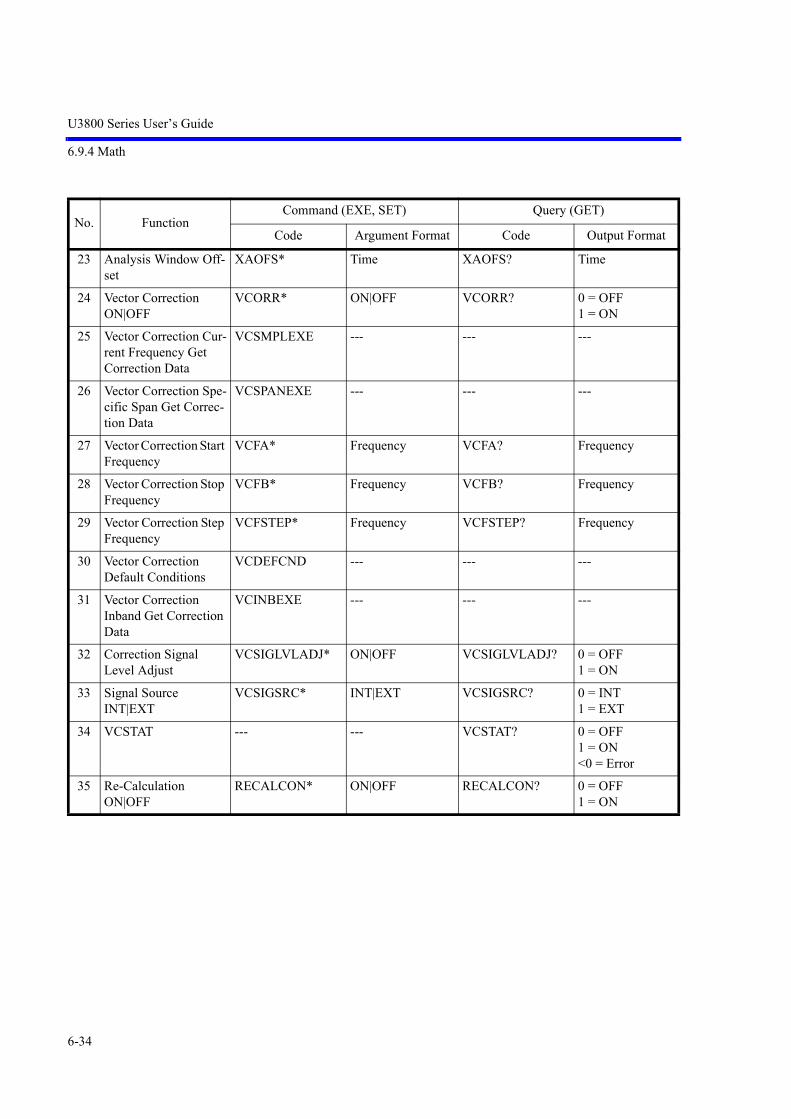
U3800 Series User’s Guide
6.9.4 Math
6-34
23 Analysis Window Off-set
XAOFS* Time XAOFS? Time
24 Vector Correction ON|OFF
VCORR* ON|OFF VCORR? 0 = OFF1 = ON
25 Vector Correction Cur-rent Frequency Get Correction Data
VCSMPLEXE --- --- ---
26 Vector Correction Spe-cific Span Get Correc-tion Data
VCSPANEXE --- --- ---
27 Vector Correction Start Frequency
VCFA* Frequency VCFA? Frequency
28 Vector Correction Stop Frequency
VCFB* Frequency VCFB? Frequency
29 Vector Correction Step Frequency
VCFSTEP* Frequency VCFSTEP? Frequency
30 Vector Correction Default Conditions
VCDEFCND --- --- ---
31 Vector Correction Inband Get Correction Data
VCINBEXE --- --- ---
32 Correction Signal Level Adjust
VCSIGLVLADJ* ON|OFF VCSIGLVLADJ? 0 = OFF1 = ON
33 Signal Source INT|EXT
VCSIGSRC* INT|EXT VCSIGSRC? 0 = INT1 = EXT
34 VCSTAT --- --- VCSTAT? 0 = OFF1 = ON<0 = Error
35 Re-Calculation ON|OFF
RECALCON* ON|OFF RECALCON? 0 = OFF1 = ON
No. FunctionCommand (EXE, SET) Query (GET)
Code Argument Format Code Output Format

U3800 Series User’s Guide
6.9.5 Ch Power Diff
6-35
6.9.5 Ch Power Diff
6.9.6 Frequency
No. FunctionCommand (EXE, SET) Query (GET)
Code Argument Format Code Output Format
1 Execute CHPDIFON* ON|OFF CHPDIFON? 0 = OFF1 = ON
2 Ch Pow Diff Result -- -- CHPDIF? Lev
No. FunctionCommand (EXE, SET) Query (GET)
Code Argument Format Code Output Format
1 Center Frequency CF* Frequency CF? Frequency
2 CF Step Size CS* Frequency CS? Frequency
3 CF Step Auto CA [*] [ON]|OFF CA? 0 = OFF (manual) 1 = ON (auto)
4 Frequency Offset FO [ON,]*FO ON|OFF
Frequency FO? FOON?
Frequency 0 = OFF 1 = ON
5 Start Frequency FA* Frequency FA? Frequency
6 Stop Frequency FB* Frequency FB? Frequency
7 Frequency Span SP* Frequency SP? Frequency
8 Full Span FS --- --- ---
9 Zero Span ZS --- --- ---
10 Last Span LTSP|LS --- --- ---
11 Frequency Setting Mode
FINPMD* CALC|TBL FINPMD? 0 = CALC 1 = TBL
12 Set Start Channel Off-set
FACHO* Frequency FACHO? Frequency
13 Set Stop Channel Off-set
FBCHO* Frequency FBCHO? Frequency
14 Start Channel Offset FACHOON* ON|OFF FACHOON? 0 = OFF 1 = ON
15 Stop Channel Offset FBCHOON* ON|OFF FBCHOON? 0 = OFF 1 = ON

U3800 Series User’s Guide
6.9.6 Frequency
6-36
16 Set Center Channel CFCH* Integer CFCH? Integer (Channel Number)
17 Set Start Channel FACH* Integer FACH? Integer (Channel Number)
18 Set Stop Channel FBCH* Integer FBCH? Integer (Channel Number)
19 Center Channel Setting CFCHON* ON|OFF CFCHON? 0 = OFF 1 = ON
20 Start Channel Setting FACHON* ON|OFF FACHON? 0 = OFF 1 = ON
21 Stop Channel Setting FBCHON* ON|OFF FBCHON? 0 = OFF 1 = ON
22 Channel Type 1 Input3 Formulas :
CHCALC1*,*,*,*,*CHCALC2 *,*,*,*,*CHCALC3*,*,*,*,*
Integer, Integer, Frequency, Frequency,Integer
--- ---
23 Formula 1 for Type 1 CHCON1* ON|OFF CHCON1? 0 = OFF 1 = ON
24 Formula 2 for Type 1 CHCON2* ON|OFF CHCON2? 0 = OFF 1 = ON
25 Formula 3 for Type 1 CHCON3* ON|OFF CHCON3? 0 = OFF 1 = ON
26 Channel Type 2 Input CHTIN*,* Integer, Frequency --- ---
27 Channel Type 2 Dele-tion
CHTDEL --- --- ---
28 Signal Ident SIGID* ON|OFF SIGID? 0 = OFF 1 = ON
29 Image Suppress IMGSP* ON|OFF IMGSP? 0 = OFF 1 = ON
30 Auto Tune TN --- --- ---
31 Peak Zoom PKZOOM --- --- ---
No. FunctionCommand (EXE, SET) Query (GET)
Code Argument Format Code Output Format

U3800 Series User’s Guide
6.9.7 Level
6-37
6.9.7 Level
No.Function
Command (EXE, SET) Query (GET)
Code Argument Format Code Output Format
1 Reference Level RL* Level RL? Level
2 Attenuation AT* DB (Integer) AT? DB (Integer)
3 Min Attenuation ATMIN* DB (Integer) ATMIN? DB (Integer)
4 Zero Attenuation ZAT --- --- ---
5 Attenuation Auto AA[*] [ON]|OFF AA? 0 = OFF (manual) 1 = ON (auto)
6 XdB/Div DD* DB (Discr. Val.: 10, 5, 2, 1, 0.5 dB)
DD? 0 = 10 dB 1 = 5 dB 2 = 2 dB 3 = 1 dB 4 = 0.5 dB -1 = others
DDB? DB
7 Linear 1 LL1 --- --- ---
8 Vertical Scale VS* LIN|LOG VS? 0 = LOG 1 = LIN
9 Level Offset RO* RO ON|OFF
DB RO? DB
ROON? 0 = OFF 1 = ON
10 Hi Sens HS[*] [ON]|OFF HS? 0 = OFF 1 = ON
11 Input OHM* Integer (Discr. Val.: 50, 75)
OHM? Integer
12 Display Unit (Level Unit)
AUNITS* DBM|DBMV|DBUV|DBEMF|DBPW| W[ATT]|V[OLT]
AUNITS? 0 = DBM 1 = DBMV 2 = DBUV 3 = DBEMF 4 = DBPW 5 = WATT 6 = VOLT
13 Correction FactorON OFF
CR ON CR OFF
--- ---
CRON? 0 = OFF 1 = ON
14 Table Input CRIN*,* Frequency, Level (DB)
--- ---
15 Table Delete CRDEL --- --- ---

U3800 Series User’s Guide
6.9.8 Bandwidth
6-38
6.9.8 Bandwidth
6.9.9 Sweep
No. FunctionCommand (EXE, SET) Query (GET)
Code Argument Format Code Output Format
1 RBW RB* Frequency RB? Frequency
2 RBW Auto BA[*] [ON]|OFF BA? 0 = OFF 1 = ON
3 VBW VB* Frequency VB? Frequency
4 VBW Auto VA[*] [ON]|OFF VA? 0 = OFF (manual) 1 = ON (auto)
5 Couple All Auto AL[*] [ON]|OFF AL? 0 = OFF 1 = ON (all auto)
6 RBW : Span CORS* CORS ON[*] CORS OFF
Ratio (float) CORS? Ratio (float)
CORSON? 0 = OFF 1 = ON
7 VBW : RBW COVR* COVR ON[*] COVR OFF
Ratio (float) COVR? Ratio (float)
COVRON? 0 = OFF 1 = ON
No. FunctionCommand (EXE, SET) Query (GET)
Code Argument Format Code Output Format
1 Sweep Time SW*|ST* Time SW?|ST? Time
2 Sweep Auto AS[*] [ON]|OFF AS? 0 = OFF (manual) 1 = ON (auto)
3 Sweep Mode --- --- SWM? 0 = Single 1 = Normal

U3800 Series User’s Guide
6.9.9 Sweep
6-39
4 Sweep Mode Normal
active Ch SN|CONTS --- --- ---
both Ch SNALL|CONTSALL
--- --- ---
Ch1 SN1|CONTS1 --- --- ---
Ch2 SN2|CONTS2 --- --- ---
5 Sweep Mode Single
active Ch SI|SNGLS --- --- ---
both Ch SIALL|SNGLSALL
--- --- ---
Ch1 SI1|SNGLS1 --- --- ---
Ch2 SI2|SNGLS2 --- --- ---
6 Take Sweep
active Ch TS --- --- ---
Ch1(*1) TSM --- --- ---
Ch2(*2) TSS --- --- ---
7 Sweep Start / Stop
active Ch SR --- --- ---
both Ch SRALL --- --- ---
Ch1(*1) SR1 --- --- ---
Ch2(*2) SR2 --- --- ---
8 Sweep Abort SWPABORT --- --- ---
9 Gated Sweep Mode GTSWP* ON|OFF GTSWP? 0 = OFF 1 = ON
10 Gate Source GTSRC* EXT|IF GTSRC? 2 = EXT 3 = IF 5 = XIF 6 = EXT2
11 Gate Slope GTSLP* (FALL|NEG|-)|(RISE|POS|+)
GTSLP? 0= RISE|POS|+ 1= FALL|NEG|-
12 Gate Delay GTPOS* Time GTPOS? Time
13 Gate Width GTWID* Time GTWID? Time
(*1) Completed when both channels are “Sweep end.”
(*2) Completed when either channel is “Sweep end.”
No. FunctionCommand (EXE, SET) Query (GET)
Code Argument Format Code Output Format
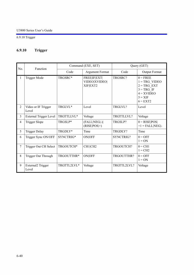
U3800 Series User’s Guide
6.9.10 Trigger
6-40
6.9.10 Trigger
No. FunctionCommand (EXE, SET) Query (GET)
Code Argument Format Code Output Format
1 Trigger Mode TRGSRC* FREE|IF|EXT|VIDEO|XVIDEO|XIF|EXT2
TRGSRC? 0 = FREE 1 = TRG_VIDEO 2 = TRG_EXT 3 = TRG_IF 4 = XVIDEO 5 = XIF 6 = EXT2
2 Video or IF Trigger Level
TRGLVL* Level TRGLVL? Level
3 External Trigger Level TRGTTLLVL* Voltage TRGTTLLVL? Voltage
4 Trigger Slope TRGSLP* (FALL|NEG|-)|(RISE|POS|+)
TRGSLP? 0 = RISE|POS| +1 = FALL|NEG|-
5 Trigger Delay TRGDLY* Time TRGDLY? Time
6 Trigger Sync ON/OFF SYNCTRIG* ON|OFF SYNCTRIG? 0 = OFF1 = ON
7 Trigger Out CH Select TRGOUTCH* CH1|CH2 TRGOUTCH? 0 = CH1 1 = CH2
8 Trigger Out Through TRGOUTTHR* ON|OFF TRGOUTTHR? 0 = OFF 1 = ON
9 External2 Trigger Level
TRGTTL2LVL* Voltage TRGTTL2LVL? Voltage

U3800 Series User’s Guide
6.9.11 Trace
6-41
6.9.11 Trace
NOTE: Three Traces are available A, B and C. In the Command List below, just replace <n> by the letter for theselected trace ie<n> = A | B | C
No. FunctionCommand (EXE, SET) Query (GET)
Code Argument Format Code Output Format
1 Trace Mode --- --- T<n>? 0 = WRITE 1 = VIEW 2 = BLANK
2 Write <n>W --- --- ---
3 View <n>V --- --- ---
4 Blank <n>B --- --- ---
5 Calc Mode Trace A CALCA* WRITE|MIN|MAX|AVG|PAVG|MAXCONT
CALCA? 0 = WRITE 1 = MIN HOLD 2 = MAX HOLD 3 = AVERAGE 4 = POWER AVG 5 = MAX HOLD
6 Calc Mode Trace B CALCB* WRITE|MIN|MAX|AVG|PAVG|MAXCONT
CALCB? 0 = WRITE 1 = MIN HOLD 2 = MAX HOLD 3 = AVERAGE 4 = POWER AVG 5 = MAX HOLD
7 Calc Mode Trace C CALCC* WRITE|MIN|MAX|AVG|PAVG|MAXCONT
CALCC? 0 = WRITE 1 = MIN HOLD 2 = MAX HOLD 3 = AVERAGE 4 = POWER AVG 5 = MAX HOLD
8 Calc Mode : Max Hold <n>MAX* ON|OFF <n>MAX? 0 = OFF 1 = ON
9 Calc Mode : Min Hold <n>MIN* ON|OFF <n>MIN? 0 = OFF 1 = ON
10 Averaging and Power Averaging Times
<n>G* Integer <n>G? Integer
11 Averaging and Power Averaging Times Active Trace
SWPCNT* Integer SWPCNT? Integer

U3800 Series User’s Guide
6.9.11 Trace
6-42
12 Average Start <n>AVG*|<n>GR
ON <n>AVG? 0 = OFF 1 = ON
13 Average Stop <n>AVG*|<n>GS
OFF
14 Average : Pause <n>GP --- <n>GP? 0 = Continue 1 = Pause
15 Average : Continue <n>GC ---
16 Average : 1 Time <n>GSGL --- <n>GSGL? 0 = sliding 1 = once
17 Average : Continuous <n>GCNT ---
18 Power Average Start <n>PAVG* ON <n>PAVG? 0 = OFF 1 = ON
19 Power Average Stop <n>PAVG* OFF
20 Power Average : Pause <n>PGP --- <n>PGP? 0 = Continue 1 = Pause
21 Power Average : Con-tinue
<n>PGC ---
22 Power Average : 1 Time
<n>PGSGL --- <n>PGSGL? 0 = sliding 1 = once
23 Power Average : Con-tinuous
<n>PGCNT ---
24 Math : Trace Store (Current trace trace n)
STORE* TRA|TRB|TRC| TRXA|TRXB TRXC
--- ---
25 Number of Trace Points
TPS|TP* 501 TP? 0 = 5011 = 1001
26 TPL|TP* 1001
27 Detector Mode Trace A
DET* NRM|POS|NEG|SMP|AVG|QP|EMCAV
DET? 0 = NRM 1 = POS 2 = NEG 3 = SMP 4 = AVG 5 = QP 6 = EMCAV
28 Detector Mode Trace B DETB* NRM|POS|NEG|SMP|AVG|QP|EMCAV
DETB? 0 = NRM 1 = POS 2 = NEG 3 = SMP 4 = AVG 5 = QP 6 = EMCAV
No. FunctionCommand (EXE, SET) Query (GET)
Code Argument Format Code Output Format

U3800 Series User’s Guide
6.9.11 Trace
6-43
29 Detector Mode Trace C DETC* NRM|POS|NEG|SMP|AVG|QP|EMCAV
DETC? 0 = NRM 1 = POS 2 = NEG 3 = SMP 4 = AVG 5 = QP 6 = EMCAV
30 Detector Mode Auto DETA<n>* ON|OFF DETA<n>? 0 = OFF 1 = ON
31 Detector Average Mode
DETAVG* RMS|VIDEO DETAVG? 0 = VIDEO 1 = RMS
32 Select Active Trace TRACESEL* TRA|TRB|TRC|TRM|TRO
TRACESEL? 0 = TRA 1 = TRB 2 = TRC3 = TRM 4 = TRO
33 Trace A I/O ASCII TAA* DDDDD<DLM> TRP (*1)
TAA? DDDDD<DLM>TRP (*1)
34 Trace A I/O Binary TBA* 2BytesTRP TBA? 2BytesTRP
35 Trace B I/O ASCII TAB* DDDDD<DLM> TRP (*1)
TAB? DDDDD<DLM>TRP (*1)
36 Trace B I/O Binary TBB* 2BytesTRP TBB? 2BytesTRP
37 Trace C I/O ASCII TAC* DDDDD<DLM> TRP (*1)
TAC? DDDDD<DLM>TRP (*1)
38 Trace C I/O Binary TBC* 2BytesTRP TBC? 2BytesTRP
39 Trace Output Fornat
40 16bits Integer FORM1 --- ---
41 16bits Integer FORM2 --- ---
42 IEEE 32bits Float FORM3 --- ---
43 IEEE 32bits Float FORM4 --- ---
44 Trace Data Binary OutChannel1 TraceAChannel2 TraceAChannel1 TraceBChannel2 TraceBChannel1 TraceCChannel2 TraceC
--- ---TBA1?TBA2?TBB1?TBB2?TBC1?TBC2?
Follows the FORM command.
(*1) TRP: Number of trace points<DLM>: Delimiter
No. FunctionCommand (EXE, SET) Query (GET)
Code Argument Format Code Output Format

U3800 Series User’s Guide
6.9.12 Trace Math
6-44
6.9.12 Trace Math
No. FunctionCommand (EXE, SET) Query (GET)
Code Argument Format Code Output Format
1 Math Trace Write MTW --- --- ---
2 Math Trace View MTV --- --- ---
3 Math Trace Blank MTB --- --- ---
4 Cross Channel Math Trace Write
OW --- --- ---
5 Cross Channel Math Trace View
OV --- --- ---
6 Cross Channel Math Trace Blank
OB --- --- ---
7 TRACE MATH IN CHANNELMath OFF
TRSUB* OFF TRSUB? 0 = OFF
8 Trace Math R/W IN CH Ascii
TAM TAM?
9 Trace Math R/W IN CH Bin
TBM TBM?
10 Trace Math R/W IN Channel1 BIN
--- TBM1?
11 Trace Math R/W IN Channel2 BIN
--- TBM2?
12 TRACE MATH IN CHANNELA - BA - CA - DLB - AB - CB - DLC - AC - BC - DL
TRSUB*
AMBAMCAMDLBMABMCBMDLCMACMBCMDL
TRSUB?
1 = A - B2 = A - C3 = A - DL4 = B - A5 = B - C6 = B - DL7 = C - A8 = C - B9 = C - DL
13 TRACE MATH CROSS CHANNEL Math OFF
TRXSUBOFF --- TRXSUB? 0 = OFF
14 Trace Math R/W CROSS CH Ascii
TAO TAO?
15 Trace Math R/W CROSS CH Bin
TBO TBO?

U3800 Series User’s Guide
6.9.12 Trace Math
6-45
16 Trace Math R/W Channel1 BIN
--- TBO1?
17 Trace Math R/W Channel2 BIN
--- TBO2?
18 TRACE MATH CROSS CHANNELCH1-CH2A - AA - BA - CA - MB - AB - BB - CB - MC - AC - BC - CC - MM - AM - BM - CM - M
TRXSUB12*
XAMAXAMBXAMCXAMMXBMAXBMBXBMCXBMMXCMAXCMBXCMCXCMMXMMAXMMBXMMCXMMM
TRXSUB?
0 = OFF1 = XAMA2 = XAMB3 = XAMC4 = XAMM5 = XBMA6 = XBMB7 = XBMC8 = XBMM9 = XCMA10 = XCMB11 = XCMC12 = XCMM13 = XMMA14 = XMMB15 = XMMC16 = XMMM
19 TRACE MATH CROSS CHANNELCH2-CH1A - AA - BA - CA - MB - AB - BB - CB - MC - AC - BC - CC - MM - AM - BM - CM - M
TRXSUB21*
XAMAXAMBXAMCXAMMXBMAXBMBXBMCXBMMXCMAXCMBXCMCXCMMXMMAXMMBXMMCXMMM
TRXSUB?
17 = XAMA18 = XAMB19 = XAMC20 = XAMM21 = XBMA22 = XBMB23 = XBMC24 = XBMM25 = XCMA26 = XCMB27 = XCMC28 = XCMM29 = XMMA30 = XMMB31 = XMMC32 = XMMM
20 TRACE MATHCROSS CHANNELCalc Mode
CALCO* OFFMINMAX
CALCO? 0 = OFF1 = MIN2 = MAX
No. FunctionCommand (EXE, SET) Query (GET)
Code Argument Format Code Output Format
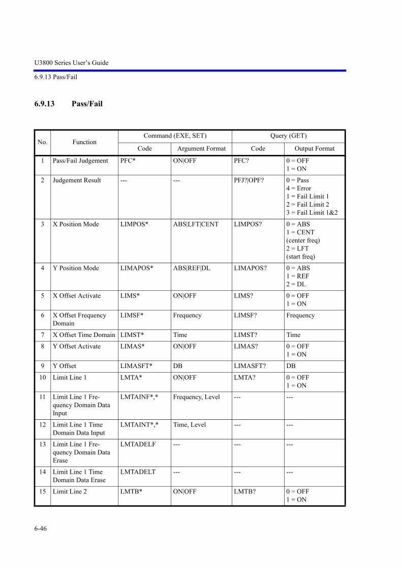
U3800 Series User’s Guide
6.9.13 Pass/Fail
6-46
6.9.13 Pass/Fail
No. FunctionCommand (EXE, SET) Query (GET)
Code Argument Format Code Output Format
1 Pass/Fail Judgement PFC* ON|OFF PFC? 0 = OFF 1 = ON
2 Judgement Result --- --- PFJ?|OPF? 0 = Pass 4 = Error 1 = Fail Limit 1 2 = Fail Limit 2 3 = Fail Limit 1&2
3 X Position Mode LIMPOS* ABS|LFT|CENT LIMPOS? 0 = ABS 1 = CENT (center freq) 2 = LFT (start freq)
4 Y Position Mode LIMAPOS* ABS|REF|DL LIMAPOS? 0 = ABS 1 = REF 2 = DL
5 X Offset Activate LIMS* ON|OFF LIMS? 0 = OFF 1 = ON
6 X Offset Frequency Domain
LIMSF* Frequency LIMSF? Frequency
7 X Offset Time Domain LIMST* Time LIMST? Time
8 Y Offset Activate LIMAS* ON|OFF LIMAS? 0 = OFF 1 = ON
9 Y Offset LIMASFT* DB LIMASFT? DB
10 Limit Line 1 LMTA* ON|OFF LMTA? 0 = OFF 1 = ON
11 Limit Line 1 Fre-quency Domain Data Input
LMTAINF*,* Frequency, Level --- ---
12 Limit Line 1 Time Domain Data Input
LMTAINT*,* Time, Level --- ---
13 Limit Line 1 Fre-quency Domain Data Erase
LMTADELF --- --- ---
14 Limit Line 1 Time Domain Data Erase
LMTADELT --- --- ---
15 Limit Line 2 LMTB* ON|OFF LMTB? 0 = OFF 1 = ON

U3800 Series User’s Guide
6.9.14 Display
6-47
6.9.14 Display
16 Limit Line 2 Fre-quency Domain Data Input
LMTBINF*,* Frequency, Level --- ---
17 Limit Line 2 Time Domain Data Input
LMTBINT*,* Time, Level --- ---
18 Limit Line 2 Fre-quency Domain Data Erase
LMTBDELF --- --- ---
19 Limit Line 2 Time Domain Data Erase
LMTBDELT --- --- ---
20 Limit Line 1 Pass Range
LARNG* ABOVE|BELOW LARNG? 0 = ABOVE 1 = BELOW
21 Limit Line 2 Pass Range
LBRNG* ABOVE|BELOW LBRNG? 0 = ABOVE 1 = BELOW
No. FunctionCommand (EXE, SET) Query (GET)
Code Argument Format Code Output Format
1 Display Line Level DLN* DLN ON[,*] DLN OFF
Level DLN? Level
DLNON? 0 = OFF 1 = ON
2 Reference Line Level RLN* RLN ON[,*] RLN OFF
Level RLN? Level
RLNON? 0 = OFF 1 = ON
3 Window Center Posi-tion
WLX* Frequency|Time WLX? Frequency|Time
4 Window Width WDX* Frequency|Time WDX? Frequency|Time
5 Window Sweep WDOSWP* ON|OFF WDOSWP? 0 = OFF 1 = ON
6 Zoom MLTSCR* ZM|FT|TT|OFF MLTSCR? 0 = OFF 1 = ZM 2 = FT 3 = TT
No. FunctionCommand (EXE, SET) Query (GET)
Code Argument Format Code Output Format

U3800 Series User’s Guide
6.9.14 Display
6-48
7 Zoom Position ZMPOS* Frequency|Time ZMPOS? Frequency|Time
8 Zoom Width ZMWID* Frequency|Time ZMWID? Frequency|Time
9 Frequency Pos FTPOS* Frequency FTPOS? Frequency
10 Select Active Context CTXTSEL* Integer (0|1) SCRSEL? 0 = CTXT A1 = CTXT B
11 Display Line IQ DLNIQ* Voltage DLNIQ? Voltage
12 Display Line Power DLNPWR* Level DLNPWR? Level
13 Display Line Freq DLNFRE* Frequency DLNFRE? Frequency
14 Display Line Phase DLNPHA* Phase DLNPHA? Phase
15 Display Line FFT DLNFFT* Level DLNFFT? Level
16 Reference Line IQ RLNIQ* Voltage RLNIQ? Voltage
17 Reference Line Power RLNPWR* Level RLNPWR? Level
18 Reference Line Freq RLNFRE* Frequency RLNFRE? Frequency
19 Reference Line Phase RLNPHA* Phase RLNPHA? Phase
20 Reference Line FFT RLNFFT* Level RLNFFT? Level
No. FunctionCommand (EXE, SET) Query (GET)
Code Argument Format Code Output Format

U3800 Series User’s Guide
6.9.15 Marker
6-49
6.9.15 Marker
<n> = 0 | 1 | 2 | 3 | 4 | 5 | 6 | 7 | 8 | 9 | 10
NOTE: Marker 0 is the reference marker.
No. FunctionCommand (EXE, SET) Query (GET)
Code Argument Format Code Output Format
1 All Markers Off MO|MKOFF --- --- ---
2 All Markers Off Except Active Marker
MLTOFF --- --- ---
3 Select Active Marker MKRSEL* <n> MKRSEL? <n>
4 Active Marker ON / OFF
MLN* ON|OFF MLN? 0 = OFF 1 = ON
5 Marker ON / OFF MLN<n>* [ON]|OFF MLN<n>? 0 = OFF 1 = ON
6 Active Marker Fre-quency
MK* Frequency|Time MK? MF?
Frequency|Time
7 Marker Frequency MF<n>* Frequency|Time MF<n>? Frequency|Time
8 Active Marker Level --- --- ML? Level
9 Marker Level --- --- ML<n>? Level
10 Active Marker Freq + Lev
--- --- MFL? Frequency|Time, Level
11 Marker Freq + Lev --- --- MFL<n>? Frequency|Time, Level
12 Active Marker Num + Stauts + Freq + Lev
--- --- MFLC? Marker Number, Sta-tus (1=ON| 0=OFF), Frequency|Time, Level
13 MarkerNum + Stauts + Freq + Lev
--- --- MFLC<n>? Marker Number, Sta-tus (1=ON|0=OFF), Frequency|Time, Level
14 Reference Marker Fre-quency Absolute Value
--- --- MDF2? MFR?
Frequency|Time
15 Reference Marker Level Absolute Value
--- --- MDL2? MLR?
Level
16 Delta Mode MKD* [ON]|OFF --- ---
17 Reference Object MKROBJ* MARK|RLIN MKROBJ? 0 = MARK 1 = RLIN
18 Fixed Marker FX* ON|OFF FX? 0 = OFF 1 = ON

U3800 Series User’s Guide
6.9.15 Marker
6-50
19 Inverse Marker REDLT* ON|OFF REDLT? 0 = OFF 1 = ON
20 Marker Step Size MPM* Frequency|Time MPM? Frequency|Time
21 Marker Step Auto MPA[*] [ON]|OFF MPA? 0 = OFF 1 = ON
22 Signal Track SG[*] [ON]|OFF SG? 0 = OFF 1 = ON
23 Signal Track Y Range SGY[ON,]* SGY ON SGY OFF
Level SGY? Level
SGYON? 0 = OFF 1 = ON
24 Active Marker Trace MKTRACE* TRA|TRB|TRC|TRM|TRO
MKTRACE? 0 = TRA 1 = TRB 2 = TRC 3 = TRM 4 = TRO
25 Marker Mode MKMODE* INDEX|VAL MKMODE? 0 = INDEX 1 = VAL
26 Display Marker List MKLST* ON|OFF MKLST? 0 = OFF 1 = ON
27 Get Marker List --- --- MLSFL? Num Marker, Active (1=ON|0=OFF), Fre-quency|Time, Level (, )
28 Dual Delta Mode MKDD* ON|OFF MKDD? 0 = OFF 1 = ON
No. FunctionCommand (EXE, SET) Query (GET)
Code Argument Format Code Output Format
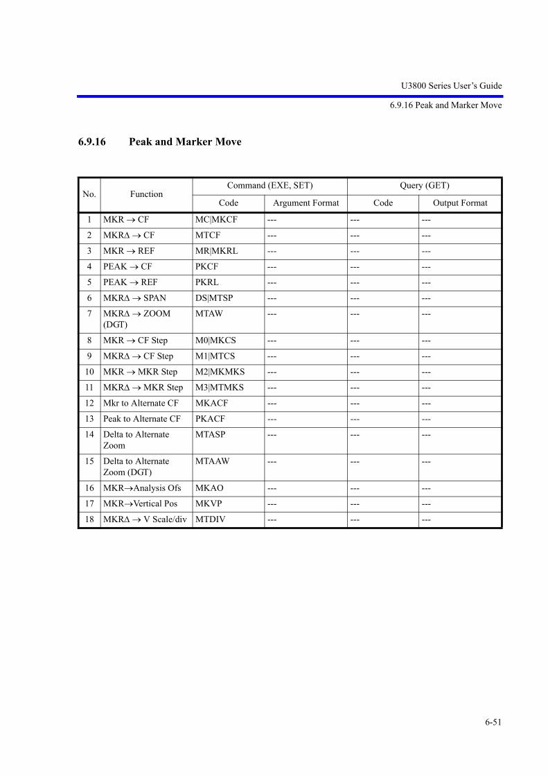
U3800 Series User’s Guide
6.9.16 Peak and Marker Move
6-51
6.9.16 Peak and Marker Move
No. FunctionCommand (EXE, SET) Query (GET)
Code Argument Format Code Output Format
1 MKR CF MC|MKCF --- --- ---
2 MKR CF MTCF --- --- ---
3 MKR REF MR|MKRL --- --- ---
4 PEAK CF PKCF --- --- ---
5 PEAK REF PKRL --- --- ---
6 MKR SPAN DS|MTSP --- --- ---
7 MKR ZOOM (DGT)
MTAW --- --- ---
8 MKR CF Step M0|MKCS --- --- ---
9 MKR CF Step M1|MTCS --- --- ---
10 MKR MKR Step M2|MKMKS --- --- ---
11 MKR MKR Step M3|MTMKS --- --- ---
12 Mkr to Alternate CF MKACF --- --- ---
13 Peak to Alternate CF PKACF --- --- ---
14 Delta to Alternate Zoom
MTASP --- --- ---
15 Delta to Alternate Zoom (DGT)
MTAAW --- --- ---
16 MKRAnalysis Ofs MKAO --- --- ---
17 MKRVertical Pos MKVP --- --- ---
18 MKR V Scale/div MTDIV --- --- ---

U3800 Series User’s Guide
6.9.17 Peak
6-52
6.9.17 Peak
No. FunctionCommand (EXE, SET) Query (GET)
Code Argument Format Code Output Format
1 Peak Search PS --- --- ---
2 Next Peak NXP --- --- ---
3 Next Peak Left NXL --- --- ---
4 Next Peak Right NXR --- --- ---
5 Min Search MIS --- --- ---
6 Next Min Peak NXM --- --- ---
7 Min Max Peak MMS --- --- ---
8 Continuous Peak CP* ON|OFF CP? 0 = OFF 1 = ON
9 Peak Y Div DY* Level Div DY? Level Div
10 Peak List Frequency Level
PLS FREQ PLS LEVEL
--- --- ---
11 X Peak Area Couple to Window
MKSX* OFF|IN|OUT MKSX? 0 = OFF 1 = IN 2 = OUT
12 X Peak Area Position MKSPOS* Frequency|Time MKSPOS? Frequency|Time
13 X Peak Area Width MKSWID* Frequency|Time MKSWID? Frequency|Time
14 Y Peak Area Couple to Display Line
MKSYDL* OFF|ABOVE|BELOW
MKSYDL? 2 = OFF 0 = ABOVE 1 = BELOW
15 Y Peak Area Couple to Limit Line 1
MKSYLA* OFF|ABOVE|BELOW
MKSYLA? 2 = OFF 0 = ABOVE 1 = BELOW
16 Y Peak Area Couple to Limit Line 2
MKSYLB* OFF|ABOVE|BELOW
MKSYLB? 2 = OFF 0 = ABOVE 1 = BELOW

U3800 Series User’s Guide
6.9.18 Measurement
6-53
6.9.18 Measurement
No. FunctionCommand (EXE, SET) Query (GET)
Code Argument Format Code Output Format
1 Noise NI* Frequency NI? Frequency
2 Noise ON + dBm/Hz NIM --- --- ---
3 Noise ON + dBV/Hz
NIU --- --- ---
4 Noise ON + dBc/Hz NIC --- --- ---
5 Noise OFF NIF --- --- ---
6 Noise Mode Query --- --- NION? 0 = OFF 1 = dBm/Hz 2 = dBV/Hz 3 = dBc/Hz
7 Noise Value --- --- NIRES? Level
8 X dB Down Level MKBW* DB MKBW? DB
9 X dB Down XDB --- --- ---
10 X dB Down Left XDL --- --- ---
11 X dB Down Right XDR --- --- ---
12 X dB Relative X dB Absolute Left X dB Absolute Right
DC0 DC1 DC2
---------
DC? 0 = Relative 1 = Absolute Left 2 = Absolute Right
13 Continuous dB Down CDB[*] [ON]|OFF CDB? 0 = OFF 1 = ON
14 Peak + X dB Down PSXDB --- --- ---
15 IM Measurement Mode
IMM[*] [ON]|OFF IMM? 0 = OFF 1 = ON
16 IM Reference Fre-quency
--- --- IMMREF? Frequency, Level
17 IM Delta Frequency --- --- IMMDF? Delta Frequency
18 IM Distortion Signal Data Readout
--- --- IMMRES? n<DLM>LL1, LJ1, UL1, UJ1<DLM>(*1)
19 IM Order Setting IMODR* Integer (3|5|7|9) IMODR? Integer (3|5|7|9)
20 IM Criteria Input 3rd Order
IMLS3* DB IMLS3? DB
21 IM Criteria Input 5th Order
IMLS5* DB IMLS5? DB
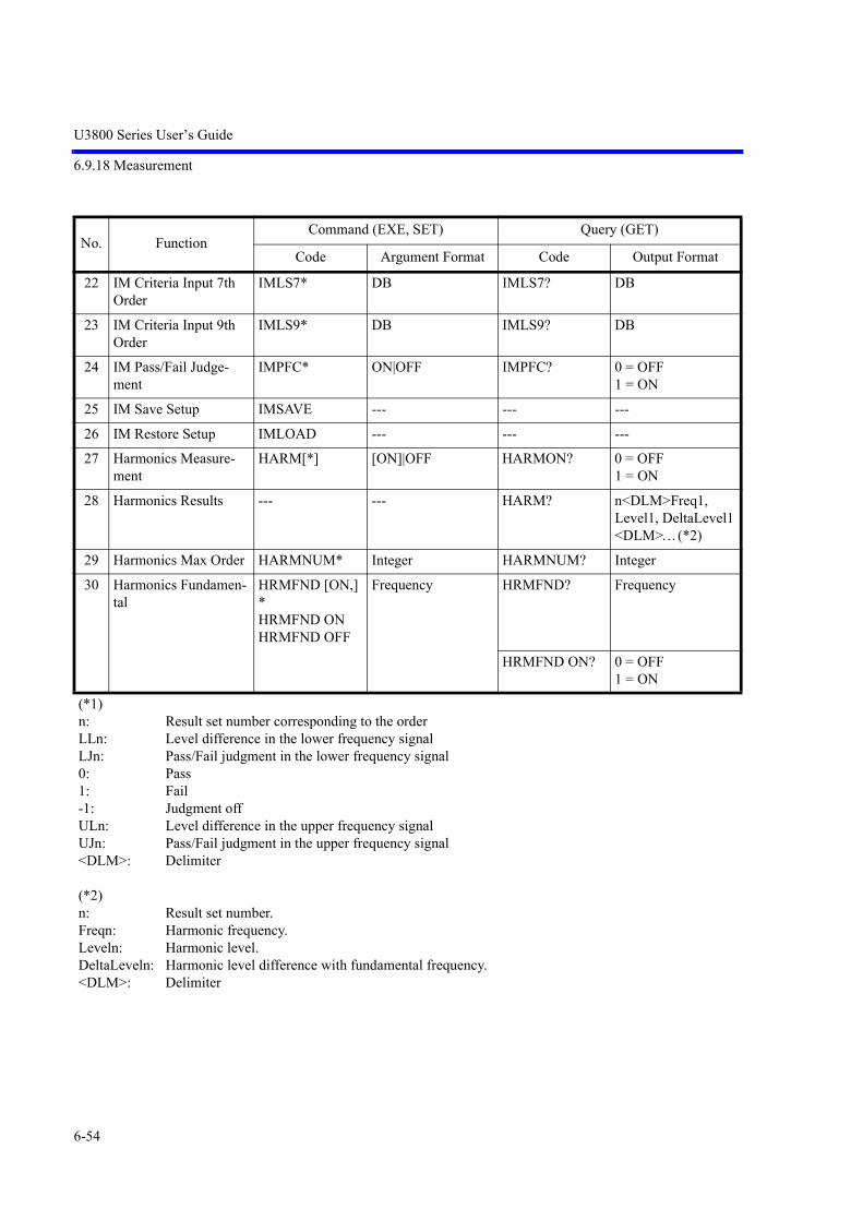
U3800 Series User’s Guide
6.9.18 Measurement
6-54
22 IM Criteria Input 7th Order
IMLS7* DB IMLS7? DB
23 IM Criteria Input 9th Order
IMLS9* DB IMLS9? DB
24 IM Pass/Fail Judge-ment
IMPFC* ON|OFF IMPFC? 0 = OFF 1 = ON
25 IM Save Setup IMSAVE --- --- ---
26 IM Restore Setup IMLOAD --- --- ---
27 Harmonics Measure-ment
HARM[*] [ON]|OFF HARMON? 0 = OFF 1 = ON
28 Harmonics Results --- --- HARM? n<DLM>Freq1, Level1, DeltaLevel1<DLM>(*2)
29 Harmonics Max Order HARMNUM* Integer HARMNUM? Integer
30 Harmonics Fundamen-tal
HRMFND [ON,] *HRMFND ON HRMFND OFF
Frequency HRMFND? Frequency
HRMFND ON? 0 = OFF 1 = ON
(*1)n: Result set number corresponding to the orderLLn: Level difference in the lower frequency signalLJn: Pass/Fail judgment in the lower frequency signal0: Pass1: Fail-1: Judgment offULn: Level difference in the upper frequency signalUJn: Pass/Fail judgment in the upper frequency signal<DLM>: Delimiter
(*2)n: Result set number.Freqn: Harmonic frequency.Leveln: Harmonic level.DeltaLeveln: Harmonic level difference with fundamental frequency.<DLM>: Delimiter
No. FunctionCommand (EXE, SET) Query (GET)
Code Argument Format Code Output Format

U3800 Series User’s Guide
6.9.18 Measurement
6-55
31 AM Modulation Mea-surement
AMMOD* ON|OFF AMMODON? 0=OFF 1=ON
32 AM Modulation Depth --- --- AMMOD? Real %
33 AM Modulation --- --- AMMF? Frequency
34 FM Measurement FMMEAS* ON|OFF FMMEASON? 0=OFF 1=ON
35 FM Frequency Devia-tion
--- --- FMMEAS? Frequency
36 Modulation Frequency to Sweep time
FMMODF[ON,]* (*3)
Frequency FMMODF? Frequency
FMMODFY* (*4)
Frequency FMMODFY? Frequency
FMMODF* ON|OFF FMMODFON? 0=OFF 1=ON
37 Sound Mode
:ON SON --- SD? 0 = OFF 1 = ON (AM) 2 = ON (FM)
:ON (AM) SAM
:ON (FM) SFM
:OFF SOF
38 Sound Volume SDV* Integer SDV? Integer
39 Demodulation Time PU* Time PU? Time
(*3) Sets the Modulation Frequency to Sweep Time mode to ON and then sets an FM frequency devia-tion value.
(*4) Sets an FM frequency deviation value without setting the Modulation Frequency to Sweep Time mode to ON.
No. FunctionCommand (EXE, SET) Query (GET)
Code Argument Format Code Output Format

U3800 Series User’s Guide
6.9.19 Counter
6-56
6.9.19 Counter
6.9.20 Power
No. FunctionCommand (EXE, SET) Query (GET)
Code Argument Format Code Output Format
1 Resolution 1 kHz CN0 --- --- ---
2 Resolution 100 Hz CN1 --- --- ---
3 Resolution 10 Hz CN2 --- --- ---
4 Resolution 1 Hz CN3 --- --- ---
5 Resolution Query --- --- CN? 0 = 1 kHz 1 = 100 Hz 2 = 10 Hz 3 = 1 Hz
6 Counter Position CNPOS* Frequency CNPOS? Frequency
7 Counter Position Auto(Position Linked to Marker)
CNPOSA[*] [ON]|OFF CNPOSA? 0 = OFF 1 = ON
8 Counter COUNT* ON|OFF COUNT? 0 = OFF 1 = ON
9 Counter Value --- --- CNRES? Frequency
No. FunctionCommand (EXE, SET) Query (GET)
Code Argument Format Code Output Format
1 Measure Mode PMEASMODE? 0 = OFF 1 = CHPOW 2 = TOTPOW 3 = AVGPOW 4 = OBW 5 = ACP 6 = SEM 7 = SPU
2 Measure OFF PMEASOFF --- --- ---
3 Measure Averaging PMEASAVG* ON|OFF PMEASAVG? 0 = OFF 1 = ON
PMEASAVGONCE*
ONCE|MULT PMEASAVGONCE?
0 = ONCE 1 = MULT
4 Measure Averaging Times
--- --- PMEASTM? Integer

U3800 Series User’s Guide
6.9.20 Power
6-57
5 Measure Trace PMEASTRACE* TRA|TRB|TRC PMEASTRACE? 0 = TRA 1 = TRB 2 = TRC
6 Channel Power ON/OFF
PWCHON[*] [ON]|OFF PWCHON? 0 = OFF 1 = ON
7 Channel Power Aver-age Times
PWCHTM* Integer PWCHTM? Integer
8 Channel Power --- --- PWCH? Level
9 Channel Power Spec-tral Density
--- --- PWCHPSD? dB
10 Power Measure Save PWCHSAVE --- --- ---
11 Power Measure Restore
PWCHLOAD --- --- ---
12 Total Power ON/OFF PWTOTA-LON[*]
[ON]|OFF PWTOTALON? 0 = OFF 1 = ON
13 Total Power Average Times
PWTOTALTM* Integer PWTOTALTM? Integer
14 Total Power --- --- PWTOTAL? Level
15 Total Power Spectral Density
--- --- PWTOTALPSD? dB
16 Power Measure Save PWTOTSAVE --- --- ---
17 Power Measure Restore
PWTOTLOAD --- --- ---
18 Average Power ON/OFF
PWAVGON[*] [ON]|OFF PWAVGON? 0 = OFF 1 = ON
19 Average Power Aver-age Times
PWAVGTM* Integer PWAVGTM? Integer
20 Average Power Range PWAVGRANGE*
FULL|WIN PWAVGRANGE?
0 = FULL 1 = WIN
21 Average Power --- --- PWAVG? Level
22 Power Measure Save PWAVGSAVE --- --- ---
23 Power Measure Restore
PWAVGLOAD --- --- ---
24 OBW Execution OBWON[*] [ON]|OFF OBWON? 0 = OFF 1 = ON
25 OBW Measurement Value
--- --- OBW? Frequency (Fc), Frequency (OBW)
26 OBW % OBWPER* Real% OBWPER? Real%
No. FunctionCommand (EXE, SET) Query (GET)
Code Argument Format Code Output Format

U3800 Series User’s Guide
6.9.20 Power
6-58
27 OBW Average Times OBWTM* Integer OBWTM? Integer
28 OBW save setup OBWSAVE --- --- ---
29 OBW restore setup OBWLOAD --- --- ---
30 ACP Execution ACP[*] [ON]|OFF ACPON? 0 = OFF 1 = ON
31 ACP Measurement Value
--- --- ACP? n<DLM>f1L, l1L, f1H, l1H<DLM>(*1)
32 ACP Average Times ACPTM* Integer ACPTM? Integer
33 ACP Reference Power Value
--- --- ACPREF? Level
34 ACP Screen ACPSCR* FULL|CARR ACPSCR? 0 = FULL 1 = CARR
35 ACP Carrier Band-width
CARRBS* ACPCBW*
Frequency CARRBS? ACPCBW?
Frequency
36 CS/BS Table Input CSBSIN*,* Frequency (CS), Frequency (BS)
--- ---
37 CS/BS Table Deletion CSBSDEL --- --- ---
38 ACP Graphics Mode ADG[*] [ON]|OFF ADG? 0 = OFF 1 = ON
39 ACP save setup ACPSAVE --- --- ---
40 ACP restore setup ACPLOAD --- --- ---
41 ACP Nyquist Filter ACPNQST* ON|OFF ACPNQST? 0 = OFF 1 = ON
42 Nyquist Symbol Rate SYMRT* Frequency SYMRT? Frequency
43 Nyquist Roll Off Fac-tor
RFACT* Real RFACT? Real
44 Spectrum Emission Mask Execution
SEMON[*] [ON]|OFF SEMON? 0 = OFF 1 = ON
45 SEM Average Times SEMTM* Integer SEMTM? Integer
46 SEM Carrier Band-width
SEMCBW* Frequency SEMCBW? Frequency
47 SEM Ref Power SEMRFCALC* CHN|PEAK SEMRFCALC? 0 = Channel 1 = Peak
48 SEM Nyquist Filter SEMNQST* ON|OFF SEMNQST? 0 = OFF 1 = ON
49 SEM save setup SEMSAVE --- --- ---
50 SEM restore setup SEMLOAD --- --- ---
No. FunctionCommand (EXE, SET) Query (GET)
Code Argument Format Code Output Format

U3800 Series User’s Guide
6.9.20 Power
6-59
51 SEM Band Table Input SEMTIN*,*,*,*,*,*,*,*
Frequency, (start) Frequency, (stop) Frequency, (ibw) dB, (limit abs start) dB, (limit abs stop) dB, (limit rel start) dB, (limit rel stop) ABS|REL|A_AND_R|A_OR_R (judge)
--- ---
52 SEM Band Table Delete
SEMTDEL --- --- ---
53 SEM Reference Power --- --- SEMRFPOW? dBm
54 SEM Measurement Value
--- --- SEM? Channel Number, Start Frequency, Stop Frequency, Frequency, Absolute Power, Relative Power, Judge (, )
55 Spurious Measure-ment Execution
SPURI* [ON|FREQ]|OFF SPURION? 0 = OFF 1 = ON
56 SPU Measurement Result
--- --- SPURI? n<DLM>m1<DLM>f1, l1, j1<DLM> fm1, lm1, jm1<DLM>m2<DLM>f1, l1, j1<DLM> fm2, lm2, jm2<DLM>mn<DLM>f1, l1, j1<DLM> fmn, lmn, jmn<DLM>(*2)
57 SPU Table Selection SPRTBL* Integer (0|1|2) SPRTBL? Integer (0|1|2)
58 SPU Table Input Freq SPRIN|SPRFIN *,*,*,*,*
Freq, (start) Freq, (stop) AUTO|Freq, (rbw) AUTO|Freq, (vbw) AUTO|Time, (swp) Level, (ref level) AUTO|Level, (att) ON|OFF, (preamp) Level (Limit)
--- ---
No. FunctionCommand (EXE, SET) Query (GET)
Code Argument Format Code Output Format

U3800 Series User’s Guide
6.9.20 Power
6-60
59 SPU Freq Table Dele-tion
SPRFDEL --- --- ---
(*1)n: Number of points (0 thru 5)fnL: nth frequency LowlnL: nth level LowfnH: nth frequency HighlnH: nth level High<DLM>: Delimiter
(*2)n: Number of measurement points (0 thru 15)m: Number of spurious signal (0 thru 10)f: Spurious frequencyl: Spurious levelj: Spurious judgment result (0:Pass, 1:Fail)<DLM>: Delimiter
No. FunctionCommand (EXE, SET) Query (GET)
Code Argument Format Code Output Format

U3800 Series User’s Guide
6.9.21 EMC
6-61
6.9.21 EMC
No. FunctionCommand (EXE, SET) Query (GET)
Code Argument Format Code Output Format
1 Correction Factor CR[*] [ON]|OFF CRON? 0 = OFF 1 = ON
2 Correction Factor Table Input
CRIN*,* Frequency, Level(DB)
--- ---
3 Correction Factor Table Deletion
CRDEL --- --- ---
4 EMC Trace DetectionOFFON
EMCON*|EMC-DET*
NRM|OFFPEAK|ON
EMCON?EMCDET?
0 = OFF3 = ON
5 EMC BWAuto200 Hz9 kHz120 kHz1 MHz
QPAUTO|QAQP0QP1QP2QP3
---QPAUTO?QA?
0 = Auto 1 = 200 Hz 2 = 9 kHz 3 = 120 kHz 4 = 1 MHz
6 Measure EMCMEAS[*] [ON]|OFF EMCMEAS? 0 = OFF1 = ON
7 Measure Time EMCMEASTIM*
EMCMEASTIM*
[ON]|OFF
Time
EMCMEASTI-MON?EMC-MEASTIM?
0 = OFF1 = ONTime
8 Horizontal Scale HSCALE* LIN|LOG HSCALE? 0 = LOG1 = LIN
9 Limit Line Margin LMTMRGN*
LMTMRGN*
ON|OFF
dB
LMTMRGNON?
LMTMRGN?
0 = OFF1 = ONdB

U3800 Series User’s Guide
6.9.22 Calibration
6-62
6.9.22 Calibration
No. FunctionCommand (EXE, SET) Query (GET)
Code Argument Format Code Output Format
1 U3841/51Calibration All (CH1)Calibration All (CH2)
CLALL* CLCH1CLCH2
--- ---
2 U3872Calibration All (CH1-L)Calibration All (CH1-H)Calibration All (CH2-L)Calibration All (CH2-H)
CLALL* CLCH1LCLCH1HCLCH2LCLCH2H
--- ---
3 Total Gain Calibration Status
--- --- CLGAIN [RFC1]|RFC2 ?(*1)
Integer 0 = OK >0 = Warning <0 = Error
4 RBW Calibration Sta-tus
--- --- CLRBW [RFC1]|RFC2 ?(*1)
Integer 0 = OK >0 = Warning <0 = Error
5 PBW Calibration Sta-tus
--- --- CLPBW [RFC1]|RFC2 ?(*1)
Integer 0 = OK >0 = Warning <0 = Error
6 ATT step Calibration --- --- CLATT[RFC1]|RFC2 ?(*1)
Integer 0 = OK>0 = Warning <0 = Error
7 CAL 10 M Reference Adjust
CLCREF* Integer CLCREF? Integer
8 CAL 10 M Reference Default
CLDREF --- --- ---
9 CAL 10 M Reference Store
CLSREF --- --- ---
10 F-Correction FC* ON|OFF FC? 0 = OFF 1 = ON
11 CAL-Correction CC* ON|OFF CC? 0 = OFF 1 = ON
(*1) RFC1 = Lo input, RFC2 = Hi input

U3800 Series User’s Guide
6.9.23 Save/Recall
6-63
6.9.23 Save/Recall
No. FunctionCommand (EXE, SET) Query (GET)
Code Argument Format Code Output Format
1 Save (File or File Number)
SV[*] :String|Integer --- ---
2 Delete (File) DEL* :String --- ---
3 Recall (File) RC* :String --- ---
4 Rename (File, New Name)
RENAME*,* :String, :String --- ---
5 Write Protect (File) WP*,* :String, ON|OFF --- ---
6 File Format FILEFORMAT* BIN|CSV|XML FILEFORMAT? 0 = BIN 1 = CSV 2 = XML
7 Media FILEMEDIA* FLASH|USB FILEMEDIA? 0 = FLASH 1 = USB
8 Auto Save Execute ASV* ON|OFF ASV? 0 = OFF 1 = ON
9 Auto Save Mode ASVMODE* LMT|SWP|TIME ASVMODE? 0 = Limit 1 = Sweep 2 = Time
10 Auto Save Max Save Count
ASVMAXSV* Integer ASVMAXSV? Integer
11 Auto Save Target CH ASVTGTCH* CH1|CH2 ASVTGTCH? 0:CH1 1:CH2
12 Auto Save Sweep Step ASVSWPSTEP* Integer ASVSWPSTEP? Integer
13 Auto Save Interval Time
ASVINTVTM* Time ASVINTVTM? Time
14 Auto Save Total Time ASVTOTALTM* Time ASVTOTALTM? Time
15 Auto Save Limit Save On
ASVLMTJDG* PASS|FAIL ASVLMTJDG? 0:PASS 1:FAIL
16 Quick Save QSV* 0 to 9 --- ---
17 Quick Recall QRC* 0 to 9 --- ---
18 Save Sampling Data IQBSV* :String --- ---
19 Recall Items Setup RCSET* ON|OFF RCSET? 0 = OFF 1 = ON
20 Recall Items Trace RCTRC* ON|OFF RCTRC? 0 = OFF 1 = ON

U3800 Series User’s Guide
6.9.24 File Management
6-64
* When specifying a file or folder name, specify it from a folder within the /adv folder (The path settingof /adv is unnecessary.)
Example 1: Save/Recall of the abc001.dat file to the adv/dat folder.
- SaveSV:dat/abc001.dat
- RecallRC:dat/abc001.dat
Example 2: Delete the abc001.dat file in the adv/dat folder.DEL:dat/abc001.dat
Example 3: Rename the abc001.dat file in the adv/dat folder.RENAME:dat/abc001.dat,:dat/abc002.dat
Example 4: Write Protect ON/OFF to the abc001.dat file in the adv/dat folder.
- Write Protect ONWP:dat/abc001.dat,ON
- Write Protect OFFWP:dat/abc001.dat,OFF
6.9.24 File Management
21 Recall Items Table RCTBL* ON|OFF RCTBL? 0 = OFF1 = ON
22 Recall Items Vector Correction
RCVCORR* ON|OFF RCVCORR? 0 = OFF1 = ON
23 Table Data Save (Type,:Filename)
TBLSV *,:* TLIM|TCHN|TACP|TSEM|TSPU|TANT,:String
--- ---
24 Table Data Recall TBLRC* :String --- ---
No. FunctionCommand (EXE, SET) Query (GET)
Code Argument Format Code Output Format
1 Reading Bitmap File --- --- BMP? Binary data <EOI>
2 Reading Portable Net-work Graphics File
--- --- PNG? Binary data <EOI>
3 Reading Image File --- --- GIMAG :String Binary data <EOI>
4 Reading Data File --- --- GDATA :String Binary data <EOI>
No. FunctionCommand (EXE, SET) Query (GET)
Code Argument Format Code Output Format

U3800 Series User’s Guide
6.9.25 Vertical Cursor
6-65
6.9.25 Vertical Cursor
6.9.26 Time Domain Analysis
No. FunctionCommand (EXE, SET) Query (GET)
Code Argument Format Code Output Format
1 V-Cursor ON/OFF VCURS* ON|OFF VCURS? 0 = OFF 1 = ON
2 V-Cursor Mode VCMODE* CSGL|CDUAL VCMODE? 0 = Single 1 = Dual
3 V-Cursor Position VCSETA*VCSETB*
Frequency, Time VCSETA?VCSETB?
Frequency, Time
4 V-Cursor Result --- --- VCRES? CH1 Hor, Ver, CH2 Hor, Ver, Dlt Hor, Ver
No. FunctionCommand (EXE, SET) Query (GET)
Code Argument Format Code Output Format
1 Time Domain Analy-sis
TDANA* ON/OFF TDANAON? 0:OFF, 1:ON
2 Analysis Offset TDAOFS* Time TDAOFS? Time
3 Analysis Window TDATIM* Time TDATIM? Time
4 Vertical Scale IQ VSCLIQ* Voltage VSCLIQ? Voltage
5 Vertical Scale Power VSCLPWR* Power VSCLPWR? Power
6 Vertical Scale Freq VSCLFRE* Frequency VSCLFRE? Frequency
7 Vertical Scale Phase VSCLPHA* Phase VSCLPHA? Phase
8 Vertical Scale FFT VSCLFFT* Level VSCLFFT? Level
9 Vertical Position IQ VPOSIQ* Position VPOSIQ? Position
10 Vertical Position Power
VPOSPWR* Position VPOSPWR? Position
11 Vertical Position Freq VPOSFRE* Position VPOSFRE? Position
12 Vertical Position Phase
VPOSPHA* Position VPOSPHA? Position
13 Vertical Position FFT VPOSFFT* Position VPOSFFT? Position
14 Measurement Func-tion
TMEAS* FRE/PHA/PWR/IQ/FFT
TMEAS? 0:FRE,1:PHA,2:PWR,3:IQ,4:FFT

U3800 Series User’s Guide
6.9.26 Time Domain Analysis
6-66
15 Capture Time CAPTIM* Time CAPTIM? Time
16 Capture BW CAPBW* Frequency CAPBW? Frequency
17 RBW TDRB* Frequency TDRB? Frequency
18 RBW Auto TDBA[*] [ON]|OFF TDBA? 0 = OFF1 = ON
19 Display Mode TDDISP* NORM|POSV|DUAL
TDDISP? 0=Normal,1=Position View,2=Dual Measure
20 Cross point Search Right
CRSPR --- --- ---
21 Cross point Search Left
CRSPL --- --- ---
22 Slope CRSSLP* UP|DN|ALL CRSSLP? 0=Up,1=Down,2=All
23 Threshold THRIQ*THRPWR*THRFRE*THRPHA*THRFFT*THRESH*
VoltdBmFrequencyPhasedBmON|OFF
THRIQ?THRPWR?THRFRE?THRPHA?THRFFT?THRESHON?
VoltdBmFrequencyPhasedBm0=OFF,1=ON
24 Measures DMEAS* OFF/DTYP/DTYN FREQ/WIDP/WIDN/HILO
DMEAS? 0:OFF,1:Pos Duty,2:Neg Duty,3:Freq,4:Pos Wid,5:Neg Wid,6: HILO
25 Measures Result --- --- DMEASRES?SWINGRES?
RealH,L,S
26 Mkr to Analysis Offs MKAO --- --- ---
27 Delta Mkr to Analy-sis Win
MTAW --- --- ---
28 Mkr to Vertical Pos MKVP --- --- ---
29 Delta Mkr to scale/div
MTDIV --- --- ---
30 IQ Output Binary --- --- IQB? 8 bytes x IQP (*1)
31 IQ Output Scale --- --- IQS? Real
32 IQ Output Points --- --- IQP? Points
33 IQ Sample Rate --- --- IQR? Frequency
No. FunctionCommand (EXE, SET) Query (GET)
Code Argument Format Code Output Format

U3800 Series User’s Guide
6.9.27 Config
6-67
6.9.27 Config
6.9.28 Preset
34 ALL IQ Sample Points
--- --- IQPAL? Points
35 Clear IQP value --- --- --- ---
36 Re-Calculation ON|OFF
RECALCON* ON|OFF RECALCON? 0 = OFF1 = ON
(*1) IQP : Number of IQ Pair Sample Points
No. FunctionCommand (EXE, SET) Query (GET)
Code Argument Format Code Output Format
1 Title LON* /*String*/ LB? String
2 Erase Title LOF --- --- ---
3 10 MHz Internal Refer-ence Signal Source
RFI --- FREF? 0 = INT 1 = EXT 2 = XTL
4 10 MHz External Ref-erence Signal Source
RFE
5 Xtal RFX
6 Reference Signal Source
RF* Frequency RF? Frequency
7 Input RF Connector RFC* RFC1|RFC2 RFC? 1 = RFC1(Lo input)2 = RFC2(Hi input)
8 Screen Copy HCOPY --- --- ---
No. FunctionCommand (EXE, SET) Query (GET)
Code Argument Format Code Output Format
1 Preset IP|*RST --- --- ---
2 Factory Init SUPIP --- --- ---
No. FunctionCommand (EXE, SET) Query (GET)
Code Argument Format Code Output Format

U3800 Series User’s Guide
6.9.29 GPIB
6-68
6.9.29 GPIB
No. FunctionCommand (EXE, SET) Query (GET)
Code Argument Format Code Output Format
1 Status Byte Clear *CLS --- --- ---
2 STB Read --- --- *STB? Integer
3 SRE Read/Write *SRE0* Integer *SRE? Integer
4 ESR Read --- --- *ESR? Integer
5 ESE Read/Write *ESE Integer *ESE? Integer
6 OSR Read --- --- OPREVT? Integer
7 OSER Read OPR* Integer OPR? Integer
8 SRQ Interrupt ON S0 --- --- ---
9 SRQ Interrupt OFF S1 --- --- ---
10 SRQ status clear S2 --- --- ---
11 Delimiter CR LF EOI DLIM0 --- --- ---
12 Delimiter LF DLIM1
13 Delimiter EOI DLIM2 --- --- ---
14 Delimiter ; DLIM5
15 Local Lockout LLO --- --- ---
16 Remote Control REN --- --- ---
17 Local Control GTL --- --- ---
18 Refresh Screen in Remote Control
SCRF[*] [ON]|OFF SCRF? ON|OFF
19 Open Menus in Remote Control
MNRF[*] [ON]|OFF MNRF? ON|OFF
20 Annotations ANNOT[*] [ON]|OFF ANNOT? ON|OFF
21 Access Channel CH1 X1 --- --- ---
22 Access Channel CH2 X2 --- --- ---

U3800 Series User’s Guide
6.9.30 Others
6-69
6.9.30 Others
No. FunctionCommand (EXE, SET) Query (GET)
Code Argument Format Code Output Format
1 Device ID Output --- --- *IDN?ID?
Maker Name, Device Name, Serial No., Revision
2 Date Setting SETDATE* Date (YYMMDD) SETDATE? Date
3 Time Setting SETTIME* Time (HHMMSS) SETTIME? Time
4 Option List --- --- *OPT? Opt1,Opt2,...,Optn<DLM>
5 Option
6 : High Stability --- --- OPT20?
7 : EMC Filter --- --- OPT28?
8 : TG -60 dBm --- --- OPT76?
9 : TG High Freq. --- --- OPT77?
10 Execute Self Test CH1 --- --- *TST? Supply_Voltage,judge<DLM>Memory,judge<DLM>CPU_Registers,judge<DLM>RF_Registers,judge<DLM>RF_PLL_Lock,judge<DLM>LO_Registers,judge<DLM>LO_PLL_Lock,judge<DLM>AIF_Registers,judge<DLM>AIF_PLL_Lock,judge<DLM>TG_Registers,judge<DLM>*Temperature,judge<DLM>RBD_PLL_Lock,judge<DLM>LD_PLL_Lock,judge<DLM>

U3800 Series User’s Guide
6.9.30 Others
6-70
11 Execute Self Test CH2 --- --- *TST? Supply_Voltage,judge<DLM>Memory,judge<DLM>CPU_Registers,judge<DLM>RF_Registers,judge<DLM>RF_PLL_Lock,judge<DLM>LO_Registers,judge<DLM>LO_PLL_Lock,judge<DLM>AIF_Registers,judge<DLM>AIF_PLL_Lock,judge<DLM>
12 Error Number --- --- ERRNO? 0 = No Error 0 = Error Code
* TG Option
No. FunctionCommand (EXE, SET) Query (GET)
Code Argument Format Code Output Format

U3800 Series User’s Guide
6.9.31 TG
6-71
6.9.31 TG
No. FunctionCommand (EXE, SET) Query (GET)
Code Argument Format Code Output Format
1 TG ON TG --- TG? 0 = OFF 1 = ON
2 TG OFF TGF --- --- ---
3 TG Level TGL* Level TGL? Level
4 TG Frequency Offset TGO[ON,]* TGO ON|OFF
Frequency TGO? TGOON?
Frequency 0 = OFF 1 = ON
5 TG Level Offset TGLO[ON,]* TGLO ON|OFF
DB TGLO? TGLOON?
DB 0 = OFF 1 = ON
6 Capture Normalize Data Active Trace
CAPND --- --- ---
7 Normalize Correction Active Trace
NORM* ON|OFF NORM? 0 = OFF 1 = ON
8 Capture Normalize Data Trace (n = A|B|C)
<n>RX --- --- ---
9 Normalize Correction Trace (n = A|B|C)
<n>NORM* ON|OFF <n>NORM? 0 = OFF 1 = ON
10 Normalize Execute Active Trace
AR --- --- ---
11 Delta Reference Line TGDLTRLN* ON|OFF TGDLTRLN? 0 = OFF 1 = ON
12 VSWR ON/OFF VSWRON [*] [ON]|OFF VSWRON? 0 = OFF 1 = ON
13 VSWR Measurement Value
--- --- VSWR? Real
14 VSWR Return Loss Value
--- --- VSWRLOSS? DB (Real)

U3800 Series User’s Guide
6.9.32 Units
6-72
6.9.32 Units
Function Code
Exponent E (see IEEE Std 488.2-1992 page 89)
GHz GZ
MHz MZ
KHz KZ
Hz HZ
DB DB
DBM DBM
DBMV DBMV
DBUV DBUV
DBEMF DBEMF
DBPW DBPW
Watt W | WATT
mW MW
Volt V | VOLT
Millivolt MV
Microvolt UV
Nanovolt NV
Second SC
Millisecond MS | MSEC
Microsecond US | USEC
Nanosecond NSEC
% % | PER
ppm PPM

U3800 Series User’s Guide
6.10 I/Q Data Output
6-73
6.10 I/Q Data Output
6.10.1 IQB Data Output
Data output by IQB? is in Binary (32bit) format, and I and Q are alternately output.
Data output by IQB? shows a relative value between I and Q, and it can be used for phase angle calculation.
Data output by IQS? shows scaling data for absolute value conversion of I and Q Pairs.
Data output by IQPAL? shows the number of all I and Q Pairs which were captured.
Data output by IQP? shows the number of samples (N) of I and Q Pairs which is returned from the next-called IQB?.
Data output by IQR? shows a sampling frequency of I and Q Pairs.
IQPRST returns the IQP? value to the initial value.
Voltages (VIN and VQN) that correspond the Nth data (IN, QN) of I and Q output can be obtained by usingthe following equations.
VIN=IN IQS [V]
VQN=QN IQS [V]
Example: Obtain all IQ data items when the return value of IQPAL? is the 4.5M sample.
1. The first IQP? returns 2Mi, so obtain the 2M sample data by IQB?.
2. The second IQP? also returns 2Mi, so obtain the 2M sample data by IQB?.
3. The third IQP? returns 0.5Mi, so obtain the 0.5M sample data by IQB?.
4. The fourth IQP? returns 0, so the obtaining of data is complete.
Repeat IQB? to obtain all data items until IQP? returns 0.
Using the TS or IQPRST command returns to the initial state.
Table 6-9 IQ-Pair data output (8xN bytes) of N obtained samples (0 to N-1)
Sample number 0 1 ... N-2 N-1
IQB?Data
I0 Q0 I1 Q1 ... ... IN-2 QN-2 IN-1 QN-1
SizeBytes
4 4 4 4 4 4 4 4 4 4

U3800 Series User’s Guide
6.10.2 IQBSV Data Output
6-74
6.10.2 IQBSV Data Output
Data output by IQBSV? is in binary format. The header data section (24 bytes), and I and Q data (dataoutput for IQB?) are output.
Table 6-10 IQBSV Data Output Format
Header data size
IQR
IQP
IQS
Capture BW
Center Frequency
I0
Q0
I1
Q1
:
IN-2
QN-2
IN-1
QN-1
4 bytes each: 24 bytes total
Refer to Section6.10.1, “IQB DataOutput.”

U3800 Series User’s Guide
6.11 Recalculation Operation Setting of Time Domain Analysis Using RECALCON
6-75
6.11 Recalculation Operation Setting of Time Domain Analysis Using RECALCON
The time domain analysis function and the between-channel vector calculation analysis function recalculate/redisplay the measurement data recorded in this instrument when the analysis function is switched or the dis-play range is changed in the RF signal record stop status. However, while operating under remote control,setting operations may became slow due to this recalculation function.
In this case, the setting operation speed can be improved by prohibiting the recalculation operation by usingthe RECALCON command.
Usage
RECALCON ON: Performs the recalculation operation. (Default setting)
RECALCON OFF: Prohibits the recalculation operation.
The recalculation operation setting that uses the RECALCON command is only valid during remote opera-tion. If remote control is cancelled by a LOCAL key operation or GTL message, the status where recalcula-tion operation is performed is set.
6.12 UNCAL Message, List of Error Messages, and Restrictions
6.12.1 How to Delete UNCAL Message for Partial FFT Analysis
The Partial FFT analysis uses time length data that is related to the Capture BW setting value (equal to thedisplayed frequency Span). If the data length required for FFT analysis is insufficient, the UNCAL mes-sage is displayed to show the displayed value may not be correct.
The UNCAL message is displayed if a relationship among each setting value of the FFT analysis datalength, which is shown in the table in Chpter 5, “Menu Map and Function Description,” Capture Time, andAnalysis Offset does not satisfy the following equation.
FFT analysis data length. (Capture Time - Analysis Offset)
To delete the UNCAL message, perform either or both of the following (1) and (2).
1. Increase the Capture Time setting value.
2. Decrease the Analysis Offset setting value.

U3800 Series User’s Guide
6.13 Multiple-Points Correction Using External Signal Sources
6-76
6.13 Multiple-Points Correction Using External Signal Sources
Multiple-points correction (Specific Span and InBand) is achieved by controlling an external signal sourceand this instrument from an external controller.
This method is applied to Section 5.2.13.1, “Power Ratio Phase Diff”, Section 5.2.13.2, “Differential”, andSection 5.2.13.4, “Math.”
Figure 6-14 Correction Connection Using External Controller and External Signal Source (GPIB Interface)
Figure 6-15 Correction Connection Using External Controller and External Signal Source (LAN Interface)
For the reference signal source of the frequency (EXT.REF.IN), press SYSTEM, Config, Frequency Refer-ence, and Frequency Reference INT|EXT|XTL(EXT). The reference signal source of the frequency is set toEXT.
When using the LAN interface, connect this instrument via an external instrument such as an Ethernet hubwhich is used to connect instruments having two or more LAN interfaces. Use a straight cable for connectionbetween the instruments. For more information, refer to Section 6.3, “LAN Remote Control System.”

U3800 Series User’s Guide
6.13.1 Remote Commands for Specific Span
6-77
6.13.1 Remote Commands for Specific Span
IMPORTANT: Specify the frequency within the following ranges:U3841: 1 MHz to 3 GHzU3851: 1 MHz to 8 GHzU3872: 1 MHz to 8 GHz (L-Input)U3872: 10 MHz to 43 GHz (H-Input)
Specify Step Freq so that the range is (Stop Freq - Start Freq)/1000 Step Freq 50 MHz. (Same setting in all models.).
Remote commands used to set frequencies (Start Freq, Stop Freq, and Step Freq) are as follows:
No. FunctionCommand (EXE, SET) Query (GET)
Code Arguments Code Output
1 Vector CorrectionSpecific Span Initialize
VCFSEXTINIT --- --- ---
2 Vector CorrectionSpecific Span Get Step Size
--- --- VCFSEXTSTPSZ? Integer
3 Vector CorrectionSpecific Span Set Index
VCFSEXTIDX* Integer --- ---
4 Vector Correction Specific Span Get Correction Data
VCFSEXTEXE --- --- ---
5 Vector CorrectionSpecific Span Finish
VCFSEXTFINISH --- --- ---
6 Vector CorrectionSpecific Span Abort
VCFSEXTABORT --- --- ---
FunctionCommand (EXE, SET) Query (GET)
Code Arguments Code Output
Vector Correction StartFrequency
VCFA* Frequency VCFA? Frequency
Vector Correction StopFrequency
VCFB* Frequency VCFB? Frequency
Vector Correction StepFrequency
VCFSTEP* Frequency VCFSTEP? Frequency

U3800 Series User’s Guide
6.13.2 Remote Commands for InBand
6-78
6.13.2 Remote Commands for InBand
For an example program that executes multiple-points correction by controlling an external signal sourceand this instrument from an external controller, refer to Section 6.14.2, “Example Program for CorrectingMultiple Points Using External Signal Source.”
No. FunctionCommand (EXE,SET) Query (GET)
Code Arguments Code Output
1 Vector CorrectionInBand Initialize
VCINBEXTINIT --- --- ---
2 Vector CorrectionInBand Get Step Size
--- --- VCINBEXTSTPSZ? Integer
3 Vector CorrectionInBand Set Index
VCINBEXTIDX* Integer --- ---
4 Vector CorrectionInBand Get FrequencyOffset
--- --- VCINBEXTFO? Fre-quency
5 Vector Correction InBand Get Correction Data
VCINBEXTEXE --- --- ---
6 Vector CorrectionInBand Finish
VCINBEXTFINISH --- --- ---
7 Vector CorrectionInBand Abort
VCINBEXTABORT --- --- ---

U3800 Series User’s Guide
6.14 Example Remote Control Program
6-79
6.14 Example Remote Control Program
This chapter describes examples of programs which control the instrument by remote.
The example programs in this chapter use Microsoft Visual Basic 6.0 language (VB). If programming in anyother language, change the description to that language.
The example program is explained, assuming that the GPIB bus controller used is a GPIB board producedby National Instruments (hereafter NI).
6.14.1 Basic Steps for GPIB Bus Control
The subsequent sections describe operations required for controlling the GPIB bus from Visual Basic 6.0/ Microsoft Visual Basic 2008 step by step.
For initialization of variables and definition of function routines that depend on Visual Basic 6.0 /Microsoft Visual Basic 2008, follow the notation rules for the Visual Basic 6.0 / Microsoft Visual Basic2008 program.
6.14.1.1 Reading GPIB Control Library
To control the GPIB board manufactured by NI from a program written in Visual Basic 6.0 / MicrosoftVisual Basic 2008 language, the VBIB-32.BAS file in which the GPIB communication interface for VisualBasic 6.0 / Microsoft Visual Basic 2008 provided by NI is described and the NIGLOBAL.BAS file andDLL file in which error and timeout values are defined must be incorporated in the Visual Basic 6.0 /Microsoft Visual Basic 2008 project.

U3800 Series User’s Guide
6.14.1 Basic Steps for GPIB Bus Control
6-80
6.14.1.2 Example Programs
Example 1 Master-resetting this instrument and setting the center frequency
Visual Basic 6.0
Microsoft Visual Basic 2008
'***************************************************************************'* Example 1 Setting the center frequency after resetting this instrument. *'***************************************************************************Private Sub CmdSetup_Click() Dim u38 As Integer Call ibdev(0, 8, 0, T30s, 1, 0, u38) ' Initialize Call ibclr(u38) ' Performs a Device Clear. Call ibwrt(u38, "IP") ' preset Call ibwrt(u38, "CF 30MZ") ' Sets the center frequency to 30 MHz. Call ibonl(u38, 0)End Sub
Imports NationalInstruments.NI4882
Module MdlManualSample_01 Private GpibDevice As Device Private Const U38_GpibBoardId As Integer = 0 Private Const U38_GpibAddress As Byte = 8 Private Const U38_GpibSecondaryAddress As Byte = 0 '*************************************************************************** '* Example 1 Setting the center frequency after resetting this instrument. * '*************************************************************************** Sub Main() Dim str As String = Space(1) GpibDevice = New Device(U38_GpibBoardId, U38_GpibAddress, U38_GpibSecondaryAddress)
Call GpibDevice.Clear() ' Performs a Device Clear. System.Console.WriteLine("preset.") Call GpibDevice.Write("IP") ' preset. System.Console.WriteLine("Sets the center frequency to 30 MHz.") Call GpibDevice.Write("CF 30MZ") ' Sets the center frequency to 30 MHz.
Call GpibDevice.Dispose()
System.Console.WriteLine("Please push Enter key.") str = System.Console.ReadLine End Sub
End Module

U3800 Series User’s Guide
6.14.1 Basic Steps for GPIB Bus Control
6-81
Example 2 Setting the start frequency to 300 kHz, setting the stop frequency to 800 kHz, and adding 50kHz to the frequency offset
Microsoft Visual Basic 2008
'*********************************************************'* Example 2 Setting the start frequency to 300 kHz, *'* setting the stop frequency to 800 kHz and *'* adding 50 kHz to the frequency offset. *'*********************************************************Private Sub CmdSetup_Click() Dim u38 As Integer Call ibdev(0, 8, 0, T30s, 1, 0, u38) ' Initialize Call ibclr(u38) ' Performs a Device Clear. Call ibwrt(u38, "FA 300KZ") ' Sets the start frequency to 300 kHz. Call ibwrt(u38, "FB 800KZ") ' Sets the stop frequency to 800 kHz. Call ibwrt(u38, "FO 50KZ") ' Adds 50 kHz to the frequency offset. Call ibonl(u38, 0)End Sub
Imports NationalInstruments.NI4882
Module MdlManualSample_02 Private GpibDevice As Device Private Const U38_GpibBoardId As Integer = 0 Private Const U38_GpibAddress As Byte = 8 Private Const U38_GpibSecondaryAddress As Byte = 0
'************************************************************************************************************************************** '* Example 2 Setting the start frequency to 300 kHz, setting the stop frequency to 800kHz and adding 50 kHz to the frequency offset. *
'************************************************************************************************************************************** Sub Main() Dim str As String = Space(1)
GpibDevice = New Device(U38_GpibBoardId, U38_GpibAddress, U38_GpibSecondaryAddress) Call GpibDevice.Clear() ' Performs a Device Clear. System.Console.WriteLine("Sets the start frequency to 300 kHz.") Call GpibDevice.Write("FA 300KZ") ' Sets the start frequency to 300 kHz. System.Console.WriteLine("Sets the stop frequency to 800 kHz.") Call GpibDevice.Write("FB 800KZ") ' Sets the stop frequency to 800 kHz. System.Console.WriteLine("Adds 50 kHz to the frequency offset.") Call GpibDevice.Write("FO 50KZ") ' Adds 50 kHz to the frequency offset.
Call GpibDevice.Dispose()
System.Console.WriteLine("Please push Enter key.") str = System.Console.ReadLine End Sub
End Module

U3800 Series User’s Guide
6.14.1 Basic Steps for GPIB Bus Control
6-82
Example 3 Setting the reference level to 87 dBV (in 5 dB/div) and the RBW to 100 kHz
Visual Basic 6.0
Microsoft Visual Basic 2008
'******************************************************************************************'* Example 3 Setting the reference level to 87 dBV (in 5 dB/div) and the RBW to 100 kHz *'******************************************************************************************Private Sub CmdSetup_Click() Dim u38 As Integer Call ibdev(0, 8, 0, T30s, 1, 0, u38) ' Initialize Call ibclr(u38) ' Performs a Device Clear. Call ibwrt(u38, "AUNITS DBUV") ' Sets the level unit to dBV. Call ibwrt(u38, "RL 87DB") ' Sets the reference level to 87 dB (V). Call ibwrt(u38, "DD 5DB") ' Sets the vertical scale to 5 dB/div. Call ibwrt(u38, "RB 100KZ") ' Sets the RBW to 100 kHz. Call ibonl(u38, 0)End Sub
Imports NationalInstruments.NI4882
Module MdlManualSample_03 Private GpibDevice As Device Private Const U38_GpibBoardId As Integer = 0 Private Const U38_GpibAddress As Byte = 8 Private Const U38_GpibSecondaryAddress As Byte = 0
'******************************************************************************************* '* Example 3 Setting the reference level to 87 dBV (in 5 dB/div) and the RBW to 100 kHz. *
'******************************************************************************************* Sub Main() Dim str As String = Space(1)
GpibDevice = New Device(U38_GpibBoardId, U38_GpibAddress, U38_GpibSecondaryAddress) Call GpibDevice.Clear() ' Performs a Device Clear. System.Console.WriteLine("Sets the level unit to dBV.") Call GpibDevice.Write("AUNITS DBUV") ' Sets the level unit to dBV. System.Console.WriteLine("Sets the reference level to 87 dB (V).") Call GpibDevice.Write("RL 87DB") ' Sets the reference level to 87 dB (V). System.Console.WriteLine("Sets the vertical scale to 5 dB/div.") Call GpibDevice.Write("DD 5DB") ' Sets the vertical scale to 5 dB/div. System.Console.WriteLine("Sets the RBW to 100 kHz.") GpibDevice.Write("RB 100KZ") ' Sets the RBW to 100 kHz.
Call GpibDevice.Dispose()
System.Console.WriteLine("Please push Enter key.") str = System.Console.ReadLine End Sub
End Module

U3800 Series User’s Guide
6.14.1 Basic Steps for GPIB Bus Control
6-83
Example 4 Setting made by using variables
Visual Basic 6.0
'****************************************************'* Example 4 Setting the instrument using variables *'****************************************************Private Sub CmdSetup_Click() Dim u38 As Integer Dim A As String Dim B As String Dim C As String Call ibdev(0, 8, 0, T30s, 1, 0, u38) ' Initialize A = "10" ' Sets the character string. B = "2" C = "20" Call ibclr(u38) ' Performs a Device Clear. Call ibwrt(u38, "CF " & A & "MZ") ' Sets the center frequency to A MHz. Call ibwrt(u38, "SP " & B & "MZ") ' Sets the span to B MHz. Call ibwrt(u38, "AT " & C & "DB") ' Sets the ATT to C dB. Call ibonl(u38, 0)End Sub

U3800 Series User’s Guide
6.14.1 Basic Steps for GPIB Bus Control
6-84
Microsoft Visual Basic 2008
Imports NationalInstruments.NI4882
Module MdlManualSample_04 Private GpibDevice As Device Private Const U38_GpibBoardId As Integer = 0 Private Const U38_GpibAddress As Byte = 8 Private Const U38_GpibSecondaryAddress As Byte = 0 '***************************************************** '* Example 4 Setting the instrument using variables. * '***************************************************** Sub Main() Dim A As String Dim B As String Dim C As String Dim str As String = Space(1)
GpibDevice = New Device(U38_GpibBoardId, U38_GpibAddress, U38_GpibSecondaryAddress) A = "10" ' Sets the character string. B = "2" C = "20" Call GpibDevice.Clear() ' Performs a Device Clear. System.Console.WriteLine("Sets the center frequency to A MHz.") Call GpibDevice.Write("CF " & A & "MZ") ' Sets the center frequency to A MHz. System.Console.WriteLine("Sets the span to B MHz.") Call GpibDevice.Write("SP " & B & "MZ") ' Sets the span to B MHz. System.Console.WriteLine("Sets the ATT to C dB.") Call GpibDevice.Write("AT " & C & "DB") ' Sets the ATT to C dB.
Call GpibDevice.Dispose()
System.Console.WriteLine("Please push Enter key.") str = System.Console.ReadLine End Sub
End Module

U3800 Series User’s Guide
6.14.1 Basic Steps for GPIB Bus Control
6-85
Example 5 Saving set values to Register 5 and recalling them from Register 5
Visual Basic 6.0
'********************************************************************************'* Example 5 Saving set values in Register 5 and recalling them from Register 5 *'********************************************************************************Private Sub CmdSetup_Click() Dim u38 As Integer Dim LabelBuff As String ' Defines the character string buffer for the Call ibdev(0, 8, 0, T30s, 1, 0, u38) ' Initialize ' label LabelBuff = "/*Cross Domain Analyzer*/" ' Sets the label. Call ibclr(u38) ' Performs a Device Clear. Call ibwrt(u38, "CF 30MZ") ' Sets the parameter. Call ibwrt(u38, "SP 1MZ") Call ibwrt(u38, "DET POS") Call ibwrt(u38, "LON " & LabelBuff) ' Sets the label. Call ibwrt(u38, "SV 5") ' Saves the data to Register 5. Call ibwrt(u38, "CF 1GZ") ' Changes the set parameters. Call ibwrt(u38, "SP 200MZ") Call ibwrt(u38, "RC 5") ' Recalls the data from Register 5. Call ibonl(u38, 0)End Sub

U3800 Series User’s Guide
6.14.1 Basic Steps for GPIB Bus Control
6-86
Microsoft Visual Basic 2008
Imports NationalInstruments.NI4882
Module MdlManualSample_05 Private GpibDevice As Device Private Const U38_GpibBoardId As Integer = 0 Private Const U38_GpibAddress As Byte = 8 Private Const U38_GpibSecondaryAddress As Byte = 0 '******************************************************************************* 'Example 5 Saving set values in Register 5 and recalling them from Register 5. * '******************************************************************************* Sub Main() Dim LabelBuff As String ' Defines the character string buffer for the label. Dim str As String = Space(1)
GpibDevice = New Device(U38_GpibBoardId, U38_GpibAddress, U38_GpibSecondaryAddress) LabelBuff = "/*Cross Domain Analyzer*/" ' Sets the label. Call GpibDevice.Clear() ' Performs a Device Clear. System.Console.WriteLine("Sets the center frequency to 30 MHz.") Call GpibDevice.Write("CF 30MZ") ' Sets the parameter. System.Console.WriteLine("Sets the span frequency to 1 MHz.") Call GpibDevice.Write("SP 1MZ") System.Console.WriteLine("Sets the detector mode trace A positive.") Call GpibDevice.Write("DET POS") System.Console.WriteLine("Sets the label.") Call GpibDevice.Write("LON " & LabelBuff) ' Sets the label. System.Console.WriteLine("Saves the data to Register 5.") Call GpibDevice.Write("SV 5") ' Saves the data to Register 5. System.Console.WriteLine("Sets the center frequency to 1 GHz.") Call GpibDevice.Write("CF 1GZ") ' Changes the set parameters. System.Console.WriteLine("Sets the span frequency to 200 MHz.") Call GpibDevice.Write("SP 200MZ") System.Console.WriteLine("Recalls the data from Register 5.") Call GpibDevice.Write("RC 5") ' Recalls the data from Register 5.
Call GpibDevice.Dispose()
System.Console.WriteLine("Please push Enter key.") str = System.Console.ReadLine End Sub
End Module

U3800 Series User’s Guide
6.14.1 Basic Steps for GPIB Bus Control
6-87
Example 6 Entering limit line1 in the table and turning limit line 1 on
Visual Basic 6.0
Microsoft Visual Basic 2008
'*********************************************************************'* Example 6 Enter Limit line1 in the table and turn Limit line 1 on *'**********************************************************************Private Sub CmdSetup_Click() Dim u38 As Integer Call ibdev(0, 8, 0, T30s, 1, 0, u38) ' Initialize Call ibclr(u38) ' Performs a Device Clear. Call ibwrt(u38, "LMTADEL") ' Clears the table used for Limit Line 1. Call ibwrt(u38, "AUNITS DBUV") ' Sets the level unit to dBV. Call ibwrt(u38, "LMTAINF 25MZ, 49.5DB") ' Enters data used by Limit Line 1. Call ibwrt(u38, "LMTAINF 35MZ, 49.5DB") Call ibwrt(u38, "LMTAINF 35MZ, 51.5DB") Call ibwrt(u38, "LMTAINF 55MZ, 51.5DB") Call ibwrt(u38, "LMTAINF 55MZ, 54.3DB") Call ibwrt(u38, "LMTAINF 65MZ, 54.3DB") Call ibwrt(u38, "LMTAINF 65MZ, 57.0DB") Call ibwrt(u38, "LMTAINF 68MZ, 57.0DB") Call ibwrt(u38, "LMTAINF 68MZ, 60.0DB") Call ibwrt(u38, "LMTAINF 75MZ, 60.0DB") Call ibwrt(u38, "LMTAINF 75MZ, 62.5DB") Call ibwrt(u38, "LMTAINF 82MZ, 62.5DB") Call ibwrt(u38, "LMTAINF 82MZ, 64.7DB") Call ibwrt(u38, "FA 0MZ") ' Sets the start frequency to 0 MHz. Call ibwrt(u38, "FB 100MZ") ' Sets the stop frequency to 100 MHz. Call ibwrt(u38, "LMTA ON") ' Turns Limit line 1 on. Call ibonl(u38, 0)End Sub
Imports NationalInstruments.NI4882
Module MdlManualSample_06 Private GpibDevice As Device Private Const U38_GpibBoardId As Integer = 0 Private Const U38_GpibAddress As Byte = 8 Private Const U38_GpibSecondaryAddress As Byte = 0 '********************************************************************** '* Example 6 Enter Limit line1 in the table and turn Limit line 1 on. * '********************************************************************** Sub Main() Dim str As String = Space(1) GpibDevice = New Device(U38_GpibBoardId, U38_GpibAddress, U38_GpibSecondaryAddress) Call GpibDevice.Clear() ' Performs a device clear. Call GpibDevice.Write("LMTADEL") ' Clears the table used for Limit Line 1. Call GpibDevice.Write("AUNITS DBUV") ' Sets the level unit to dBV. ' Enters data used by Limit Line 1.

U3800 Series User’s Guide
6.14.1 Basic Steps for GPIB Bus Control
6-88
System.Console.WriteLine("Sets the limit frequency to 25 MHz and limit level 49.5dBV.") Call GpibDevice.Write("LMTAINF 25MZ, 49.5DB") System.Console.WriteLine("Sets the limit frequency to 35 MHz and limit level 49.5dBV.") Call GpibDevice.Write("LMTAINF 35MZ, 49.5DB") System.Console.WriteLine("Sets the limit frequency to 35 MHz and limit level 51.5dBV.") Call GpibDevice.Write("LMTAINF 35MZ, 51.5DB") System.Console.WriteLine("Sets the limit frequency to 55 MHz and limit level 51.5dBV.") Call GpibDevice.Write("LMTAINF 55MZ, 51.5DB") System.Console.WriteLine("Sets the limit frequency to 55 MHz and limit level 54.3dBV.") Call GpibDevice.Write("LMTAINF 55MZ, 54.3DB") System.Console.WriteLine("Sets the limit frequency to 65 MHz and limit level 54.3dBV.") Call GpibDevice.Write("LMTAINF 65MZ, 54.3DB") System.Console.WriteLine("Sets the limit frequency to 65 MHz and limit level 57.0dBV.") Call GpibDevice.Write("LMTAINF 65MZ, 57.0DB") System.Console.WriteLine("Sets the limit frequency to 68 MHz and limit level 57.0dBV.") Call GpibDevice.Write("LMTAINF 68MZ, 57.0DB") System.Console.WriteLine("Sets the limit frequency to 68 MHz and limit level 60.0dBV.") Call GpibDevice.Write("LMTAINF 68MZ, 60.0DB") System.Console.WriteLine("Sets the limit frequency to 75 MHz and limit level 60.0dBV.") Call GpibDevice.Write("LMTAINF 75MZ, 60.0DB") System.Console.WriteLine("Sets the limit frequency to 75 MHz and limit level 62.5dBV.") Call GpibDevice.Write("LMTAINF 75MZ, 62.5DB") System.Console.WriteLine("Sets the limit frequency to 82 MHz and limit level 62.5dBV.") Call GpibDevice.Write("LMTAINF 82MZ, 62.5DB") System.Console.WriteLine("Sets the limit frequency to 82 MHz and limit level 64.7dBV.") Call GpibDevice.Write("LMTAINF 82MZ, 64.7DB") System.Console.WriteLine("Sets the start frequency to 0 MHz.") Call GpibDevice.Write("FA 0MZ") ' Sets the start frequency to 0 MHz. System.Console.WriteLine("Sets the stop frequency to 100 MHz.") Call GpibDevice.Write("FB 100MZ") ' Sets the stop frequency to 100 MHz. System.Console.WriteLine("Turns Limit line 1 on.") Call GpibDevice.Write("LMTA ON") ' Turns Limit line 1 on.
Call GpibDevice.Dispose()
System.Console.WriteLine("Please push Enter key.") str = System.Console.ReadLine End Sub
End Module

U3800 Series User’s Guide
6.14.1 Basic Steps for GPIB Bus Control
6-89
6.14.1.3 Sample Programs for Reading Data
In order to output measurement data or settings, use the “xx?” command. This ensures that the data is readwhen this instrument is in the talker mode. Available output formats are listed in the table below. Thedelimiter positioned at the end of data can be specified from 5 types (refer to “Others” in the GPIB codelist). Once set, “xx?” command continues to operate until it is changed.
<Supplement>1 = Sign (a space for plus sign; “-” for minus sign)2 = Mantissa of data3 = Exponent of data4 = Delimiter (CR/LF in initial setting can be changed with “DLn” code.)
Table 6-11 Data Output Format
Output Format
Frequency D.DDDDDDDDDDD E DD CR LF
The maximum size of data 1 + 2 + 3 is 19 bytes long and the unit is Hz
ExampleSpecify “CF?” and output as center frequency.
Level D.DDDDDDD E DD CR LF
The maximum size of data 1 + 2 + 3 is 19 bytes long and the unit depends on the setting of each UNIT.
ExampleSpecify “ML?” and output as the marker level.
Time D.DDD E DD CR LF
The maximum size of data 1 + 2 + 3 is 19 bytes and the unit is sec
ExampleSpecify “SW?” and the output sweep time.
Constant DDDD CR LF
The maximum size of the data in bytes corresponds to the maximum size of the output data
ExampleThe ON/OFF status or Averaging count is output
1 2 3 4
1 2 3 4
1 2 3
4
2 4

U3800 Series User’s Guide
6.14.1 Basic Steps for GPIB Bus Control
6-90
Example 1 Reading and displaying the marker level
Visual Basic 6.0
'******************************************************'* Example 1 Reading and displaying the marker level. *'******************************************************Private Sub CmdReadMarkerLevel_Click() Dim u38 As Integer Dim Rdbuff As String Dim sep As Integer Call ibdev(0, 8, 0, T30s, 1, 0, u38) ' Initialize Call ibclr(u38) ' Performs a Device Clear. Call ibwrt(u38, "CF 30MZ") ' Sets the parameter. Call ibwrt(u38, "SP 1MZ") Call ibwrt(u38, "MLN ON") ' Marker ON Call ibwrt(u38, "MK 30MZ") ' Sets the marker to 30 MHz. Call ibwrt(u38, "TS") Call ibwrt(u38, "ML?") ' Requests the value of the marker level. Rdbuff = Space(30) ' Allocates 30 bytes to the buffer area. Call ibrd(u38, Rdbuff) ' Reads the data (30 bytes Max.). sep = InStr(1, Rdbuff, vbCrLf, 0) ' Checks the number of character up to the delimiter. Label.Caption = "MarkerLevel = " & Left(Rdbuff, sep - 1) ' Displays the data on the screen. ' An example display: ' MarkerLevel = -88.1875 Call ibonl(u38, 0)End Sub

U3800 Series User’s Guide
6.14.1 Basic Steps for GPIB Bus Control
6-91
Microsoft Visual Basic 2008
Imports NationalInstruments.NI4882
Module MdlManualSample_01 Private GpibDevice As Device Private Const U38_GpibBoardId As Integer = 0 Private Const U38_GpibAddress As Byte = 8 Private Const U38_GpibSecondaryAddress As Byte = 0 '****************************************************** '* Example 1 Reading and displaying the marker level. * '****************************************************** Sub Main() Dim Rdbuff As String Dim sep As Integer Dim str As String = Space(1)
GpibDevice = New Device(U38_GpibBoardId, U38_GpibAddress,U38_GpibSecondaryAddress) Call GpibDevice.Clear() ' Performs a device clear. System.Console.WriteLine("Sets the center frequency to 30 MHz.") Call GpibDevice.Write("CF 30MZ") ' Sets the parameter. System.Console.WriteLine("Sets the span frequency to 1 MHz.") Call GpibDevice.Write("SP 1MZ") System.Console.WriteLine("Marker ON.") Call GpibDevice.Write("MLN ON") ' Marker ON. System.Console.WriteLine("Sets the marker to 30 MHz.") Call GpibDevice.Write("MK 30MZ") ' Sets the marker to 30 MHz. System.Console.WriteLine("Single sweep.") Call GpibDevice.Write("TS") System.Console.WriteLine("Requests the value of the marker level.") Call GpibDevice.Write("ML?") ' Requests the value of the marker level. Rdbuff = Space(30) ' Allocates 30 bytes to the buffer area. Rdbuff = GpibDevice.ReadString ' Reads the data (30 bytes Max.). sep = InStr(1, Rdbuff, vbCr & vbLf, 0) ' Checks the number of character up to thedelimiter. ' Displays the data on the screen. ' An example display: ' MarkerLevel = -88.1875 System.Console.WriteLine("MarkerLevel = " & Left(Rdbuff, sep - 1))
Call GpibDevice.Dispose()
System.Console.WriteLine("Please push Enter key.") str = System.Console.ReadLine End SubEnd Module
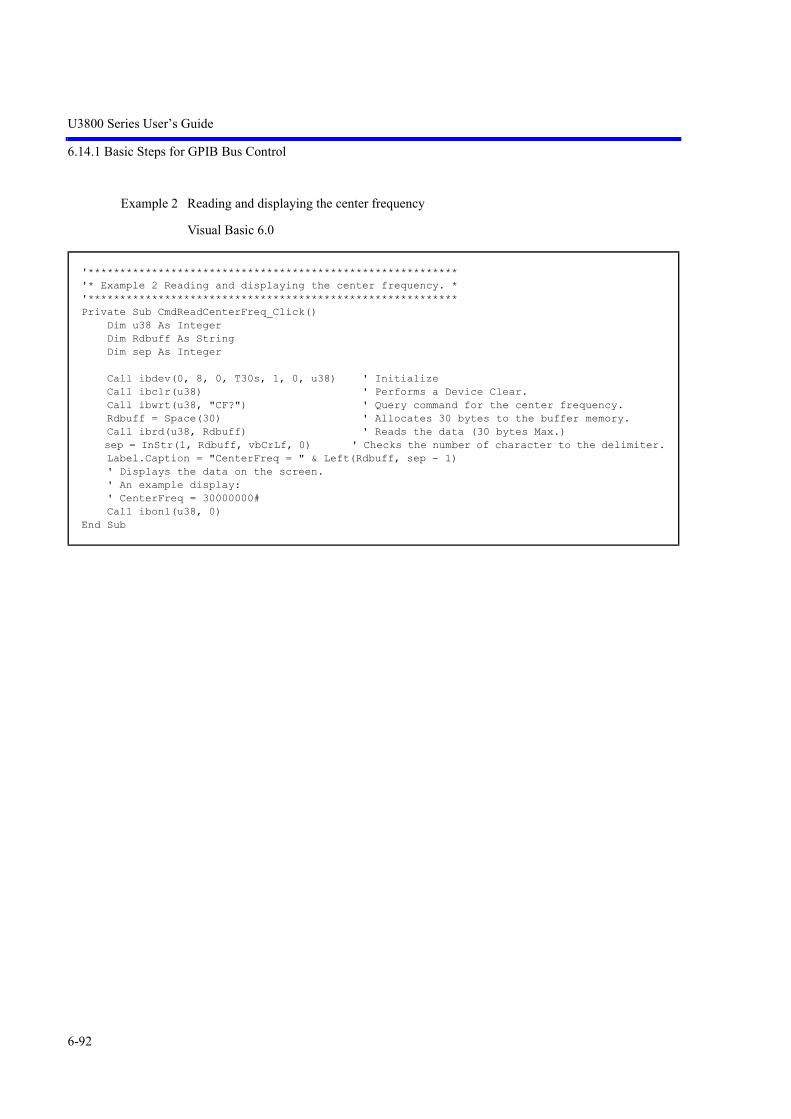
U3800 Series User’s Guide
6.14.1 Basic Steps for GPIB Bus Control
6-92
Example 2 Reading and displaying the center frequency
Visual Basic 6.0
'**********************************************************'* Example 2 Reading and displaying the center frequency. *'**********************************************************Private Sub CmdReadCenterFreq_Click() Dim u38 As Integer Dim Rdbuff As String Dim sep As Integer Call ibdev(0, 8, 0, T30s, 1, 0, u38) ' Initialize Call ibclr(u38) ' Performs a Device Clear. Call ibwrt(u38, "CF?") ' Query command for the center frequency. Rdbuff = Space(30) ' Allocates 30 bytes to the buffer memory. Call ibrd(u38, Rdbuff) ' Reads the data (30 bytes Max.) sep = InStr(1, Rdbuff, vbCrLf, 0) ' Checks the number of character to the delimiter. Label.Caption = "CenterFreq = " & Left(Rdbuff, sep - 1) ' Displays the data on the screen. ' An example display: ' CenterFreq = 30000000# Call ibonl(u38, 0)End Sub

U3800 Series User’s Guide
6.14.1 Basic Steps for GPIB Bus Control
6-93
Microsoft Visual Basic 2008
Imports NationalInstruments.NI4882
Module MdlManualSample_02 Private GpibDevice As Device Private Const U38_GpibBoardId As Integer = 0 Private Const U38_GpibAddress As Byte = 8 Private Const U38_GpibSecondaryAddress As Byte = 0 '********************************************************** '* Example 2 Reading and displaying the center frequency. * '********************************************************** Sub Main() Dim Rdbuff As String Dim sep As Integer Dim str As String = Space(1)
GpibDevice = New Device(U38_GpibBoardId, U38_GpibAddress, U38_GpibSecondaryAddress) Call GpibDevice.Clear() ' Performs a Device Clear. System.Console.WriteLine("Query command for the center frequency.") Call GpibDevice.Write("CF?") ' Query command for the center frequency. Rdbuff = Space(30) ' Allocates 30 bytes to the buffer memory. Rdbuff = GpibDevice.ReadString ' Reads the data (30 bytes Max.) sep = InStr(1, Rdbuff, vbCr & vbLf, 0) ' Checks the number of character to thedelimiter. ' Displays the data on the screen. System.Console.WriteLine("CenterFreq = " & Left(Rdbuff, sep - 1))
Call GpibDevice.Dispose()
System.Console.WriteLine("Please push Enter key.") str = System.Console.ReadLine End Sub
End Module

U3800 Series User’s Guide
6.14.1 Basic Steps for GPIB Bus Control
6-94
Example 3 Reading and displaying the level and its display unit
Visual Basic 6.0
'********************************************************************'* Example 3 Reading the level and display unit and displaying them *'********************************************************************Private Sub CmdReadRefLevel_Click() Dim u38 As Integer Dim Rdbuff As String Dim sep As Integer Call ibdev(0, 8, 0, T30s, 1, 0, u38) ' Initialize Call ibclr(u38) ' Performs a Device Clear. Call ibwrt(u38, "RL?") ' Query command for the reference level. Rdbuff = Space(30) ' Allocates 30 bytes to the buffer memory. Call ibrd(u38, Rdbuff) ' Reads the data from the spectrum analyzer. sep = InStr(1, Rdbuff, vbCrLf, 0) ' Checks the number of characters to the delimiter. Label.Caption = "RefLevel = " & Left(Rdbuff, sep - 1) ' Display the data on the screen. Call ibwrt(u38, "AUNITS?") ' Requests the level unit. Rdbuff = Space(3) Call ibrd(u38, Rdbuff) sep = InStr(1, Rdbuff, vbCrLf, 0) ' Checks the number of characters to the delimiter. Label.Caption = Label.Caption & vbCrLf & "UNIT = " & Left(Rdbuff, sep - 1) ' Displays the previous result, followed by a return mark and the most recent result. ' An example display: ' RefLevel = 0# ' UNIT = 0 Call ibonl(u38, 0)End Sub

U3800 Series User’s Guide
6.14.1 Basic Steps for GPIB Bus Control
6-95
Microsoft Visual Basic 2008
Imports NationalInstruments.NI4882
Module MdlManualSample_03 Private GpibDevice As Device Private Const U38_GpibBoardId As Integer = 0 Private Const U38_GpibAddress As Byte = 8 Private Const U38_GpibSecondaryAddress As Byte = 0
'********************************************************************* '* Example 3 Reading the level and display unit and displaying them. * '********************************************************************* Sub Main() Dim Rdbuff As String Dim sep As Integer Dim tmp As String = Space(256) Dim str As String = Space(1)
GpibDevice = New Device(U38_GpibBoardId, U38_GpibAddress, U38_GpibSecondaryAddress) Call GpibDevice.Clear() ' Performs a Device Clear. System.Console.WriteLine("Query command for the reference level.") Call GpibDevice.Write("RL?") ' Query command for the reference level. Rdbuff = Space(30) ' Allocates 30 bytes to the buffer memory. Rdbuff = GpibDevice.ReadString ' Reads the data from the U3800. sep = InStr(1, Rdbuff, vbCr & vbLf, 0) ' Checks the number of characters to thedelimiter. tmp = "RefLevel = " & Left(Rdbuff, sep - 1) System.Console.WriteLine(tmp) ' Display the data on the screen. System.Console.WriteLine("Requests the level unit.") Call GpibDevice.Write("AUNITS?") ' Requests the level unit. Rdbuff = Space(3) Rdbuff = GpibDevice.ReadString sep = InStr(1, Rdbuff, vbCr & vbLf, 0) ' Checks the number of characters to thedelimiter. ' Displays the previous result, followed by a return mark and the most recent result. System.Console.WriteLine(tmp & vbCrLf & "UNIT = " & Left(Rdbuff, sep - 1))
Call GpibDevice.Dispose()
System.Console.WriteLine("Please push Enter key.") str = System.Console.ReadLine End Sub
End Module

U3800 Series User’s Guide
6.14.1 Basic Steps for GPIB Bus Control
6-96
Example 4 Executing the 6 dB-down operation, reading the frequency and level, and displaying them
Visual Basic 6.0
'*****************************************************************************************************'* Example 4 Executing the 6 dB-down operation, reading the frequency and level and displayingthem. *'*****************************************************************************************************Private Sub Cmd6dBDownOpe_Click() Dim u38 As Integer Dim Rdbuff As String Dim sep As Integer Call ibdev(0, 8, 0, T30s, 1, 0, u38) ' Initialize Call ibclr(u38) ' Performs a Device Clear. Call ibwrt(u38, "CF 30MZ") ' Sets the parameter. Call ibwrt(u38, "SP 20MZ") Call ibwrt(u38, "MKBW 6DB") ' Sets a 6 dB down measurement. Call ibwrt(u38, "PS") ' Executes the peak search. Call ibwrt(u38, "XDB") ' Performs the 6 dB down measurement. Call ibwrt(u38, "MFL?") ' Requests the value of the marker level and frequency. Rdbuff = Space(50) ' Allocates the buffer memory space to 50 bytes. Call ibrd(u38, Rdbuff) ' Reads the data (50 bytes Max.) from the u3800. sep = InStr(1, Rdbuff, vbCrLf, 0) ' Checks the number of characters to the delimiter. Label.Caption = "Marker Freq && Level = " & Left(Rdbuff, sep - 1) ' Displays the data on the screen. ' An example display: ' Marker Freq & Level = 200000#, 1.0234375 Call ibonl(u38, 0)End Sub

U3800 Series User’s Guide
6.14.1 Basic Steps for GPIB Bus Control
6-97
Microsoft Visual Basic 2008
Imports NationalInstruments.NI4882
Module MdlManualSample_04 Private GpibDevice As Device Private Const U38_GpibBoardId As Integer = 0 Private Const U38_GpibAddress As Byte = 8 Private Const U38_GpibSecondaryAddress As Byte = 0
'***************************************************************************************************** '* Example 4 Executing the 6 dB-down operation, reading the frequency and level and dis-playing them. *
'***************************************************************************************************** Sub Main() Dim Rdbuff As String Dim sep As Integer Dim str As String = Space(1)
GpibDevice = New Device(U38_GpibBoardId, U38_GpibAddress, U38_GpibSecondaryAddress) Call GpibDevice.Clear() ' Performs a Device Clear. System.Console.WriteLine("Sets the center frequency to 30 MHz.") Call GpibDevice.Write("CF 30MZ") ' Sets the parameter. System.Console.WriteLine("Sets the span frequency to 20 MHz.") Call GpibDevice.Write("SP 20MZ") System.Console.WriteLine("Sets a 6 dB down measurement.") Call GpibDevice.Write("MKBW 6DB") ' Sets a 6 dB down measurement. System.Console.WriteLine("Executes the peak search.") Call GpibDevice.Write("PS") ' Executes the peak search. System.Console.WriteLine("Performs the 6 dB down measurement.") Call GpibDevice.Write("XDB") ' Performs the 6 dB down measurement. System.Console.WriteLine("Requests the value of the marker level and frequency. ") Call GpibDevice.Write("MFL?") ' Requests the value of the marker level andfrequency. Rdbuff = Space(50) ' Allocates the buffer memory space to 50 bytes. Rdbuff = GpibDevice.ReadString ' Reads the data (50 bytes Max.) from the U3800. sep = InStr(1, Rdbuff, vbCr & vbLf, 0) ' Checks the number of characters to thedelimiter. ' Displays the data on the screen. ' An example display: ' Marker(Freq & Level = +200000.0, +1.0234375) System.Console.WriteLine("Marker Freq & Level = " & Left(Rdbuff, sep - 1))
Call GpibDevice.Dispose()
System.Console.WriteLine("Please push Enter key.") str = System.Console.ReadLine End Sub
End Module

U3800 Series User’s Guide
6.14.1 Basic Steps for GPIB Bus Control
6-98
Example 5 Measuring and displaying OBW
Visual Basic 6.0
Microsoft Visual Basic 2008
'*********************************************'* Example 5 Measuring OBW and displaying it *'*********************************************Private Sub CmdMeasOBW_Click() Dim u38 As Integer Dim LENG1 As Integer, LENG2 As Integer Dim OBW As String Dim FC As String Dim Rdbuff As String Call ibdev(0, 8, 0, T30s, 1, 0, u38) ' Initialize Call ibclr(u38) ' Performs a Device Clear. Call ibwrt(u38, "CF 30MZ") ' Sends the command already set. Call ibwrt(u38, "SP 1MZ") Call ibwrt(u38, "MLN ON") ' Marker ON Call ibwrt(u38, "MK 30MZ") Call ibwrt(u38, "OBWON ON") Call ibwrt(u38, "TS") Call ibwrt(u38, "OBW?") ' Sends the query command. Rdbuff = Space(60) ' Allocates the area to the read buffer. Call ibrd(u38, Rdbuff) ' Reads the read buffer (the maximum number ofbytes to be output is determined by the buffer area size). ' Formatting output character string LENG1 = InStr(1, Rdbuff, Chr(44), 0) ' Searches for the first comma. FC = Mid(Rdbuff, 1, LENG1 - 1) ' Reads the character before the comma. DoEvents LENG2 = InStr((LENG1 + 1), Rdbuff, vbCr, 0) ' Determines the last data by searching forthe delimiter. OBW = Mid(Rdbuff, (LENG1 + 1), (LENG2 - LENG1 - 1)) ' Reads the data between the secondcomma and the delimiter. Label.Caption = "OBW = " & OBW & vbCrLf & "Fc = " & FC & vbCrLf ' Displays the data on the screen. ' An example display: ' OBW = 981000# ' FC = 30002500# Call ibonl(u38, 0)End Sub
Imports NationalInstruments.NI4882
Module MdlManualSample_05 Private GpibDevice As Device Private Const U38_GpibBoardId As Integer = 0 Private Const U38_GpibAddress As Byte = 8 Private Const U38_GpibSecondaryAddress As Byte = 0 '********************************************** '* Example 5 Measuring OBW and displaying it. * '**********************************************

U3800 Series User’s Guide
6.14.1 Basic Steps for GPIB Bus Control
6-99
Sub Main() Dim Rdbuff As String Dim LENG1 As Integer, LENG2 As Integer Dim OBW As String Dim FC As String Dim str As String = Space(1)
GpibDevice = New Device(U38_GpibBoardId, U38_GpibAddress, U38_GpibSecondaryAddress) Call GpibDevice.Clear() ' Performs a Device Clear. System.Console.WriteLine("Sets the center frequency to 30 MHz.") Call GpibDevice.Write("CF 30MZ") ' Sends the command already set. System.Console.WriteLine("Sets the span frequency to 1 MHz.") Call GpibDevice.Write("SP 1MZ") System.Console.WriteLine("Marker ON.") Call GpibDevice.Write("MLN ON") ' Marker ON. System.Console.WriteLine("Sets the marker frequency to 30 MHz.") Call GpibDevice.Write("MK 30MZ") System.Console.WriteLine("OBW ON.") Call GpibDevice.Write("OBWON ON") System.Console.WriteLine("Single Sweep.") Call GpibDevice.Write("TS") System.Console.WriteLine("Sends the query OBW command.") Call GpibDevice.Write("OBW? ") ' Sends the query command. Rdbuff = Space(60) ' Allocates the area to the read buffer. Rdbuff = GpibDevice.ReadString ' Reads the read buffer (the maximum number of bytesto be output is determined by the buffer area size). ' Formatting output character string. LENG1 = InStr(1, Rdbuff, Chr(44), 0) ' Searches for the first comma. FC = Mid(Rdbuff, 1, LENG1 - 1) ' Reads the character before the comma. LENG2 = InStr((LENG1 + 1), Rdbuff, vbCr, 0) 'Determines the last data by searching for the delimiter. OBW = Mid(Rdbuff, (LENG1 + 1), (LENG2 - LENG1 - 1)) ' Reads the data between the second comma and the delimiter. ' Displays the data on the screen. ' An example display: ' OBW = +981000.0 ' FC = +30002500.0 System.Console.WriteLine("OBW = " & OBW & vbCr & vbLf & "Fc = " & FC & vbCr & vbLf)
Call GpibDevice.Dispose()
System.Console.WriteLine("Please push Enter key.") str = System.Console.ReadLine End Sub
End Module

U3800 Series User’s Guide
6.14.1 Basic Steps for GPIB Bus Control
6-100
Example 6 Reading and displaying the first, second, and third largest peak level values of the signal
Visual Basic 6.0
'******************************************************************'* Example 6 Reading and displaying the three largest peak levels *'******************************************************************Private Sub CmdPeakLevel_Click() Dim u38 As Integer Dim Rdbuff As String Dim pk1, pk2, pk3 As String Call ibdev(0, 8, 0, T30s, 1, 0, u38) ' Initialize Call ibclr(u38) ' Performs a Device Clear. Call ibwrt(u38, "CF 0MZ") ' Applies the settings. Call ibwrt(u38, "SP 100MZ") Call ibwrt(u38, "TS") Call ibwrt(u38, "PS") ' Executes the peak search. Call ibwrt(u38, "ML?") ' Query command to search for the marker level Rdbuff = Space(25) ' Allocates the buffer memory. Call ibrd(u38, Rdbuff) ' Receives the output. pk1 = Left(Rdbuff, (InStr(1, Rdbuff, vbCr, 1) - 1)) ' Reads the data between the startingpoint and the delimiter. Call ibwrt(u38, "NXP") ' Searches for the next peak. Call ibwrt(u38, "ML?") Rdbuff = Space(25) Call ibrd(u38, Rdbuff) pk2 = Left(Rdbuff, (InStr(1, Rdbuff, vbCr, 1) - 1)) ' Reads the data between the startingpoint and the delimiter. Call ibwrt(u38, "NXP") Call ibwrt(u38, "ML?") Rdbuff = Space(25) Call ibrd(u38, Rdbuff) pk3 = Left(Rdbuff, (InStr(1, Rdbuff, vbCr, 1) - 1)) ' Reads the data between the startingpoint and the delimiter. Label.Caption = "1st PK = " & pk1 & vbCrLf & "2nd PK = " & pk2 & vbCrLf & "3rd PK = " &pk3 & vbCrLf ' Displays the data on the screen. ' An example display: ' 1 st PK = -85.5390625 ' 2 nd PK = -70.046875 ' 3 rd PK = -86.5546875 Call ibonl(u38, 0)End Sub

U3800 Series User’s Guide
6.14.1 Basic Steps for GPIB Bus Control
6-101
Microsoft Visual Basic 2008
Imports NationalInstruments.NI4882
Module MdlManualSample_06 Private GpibDevice As Device Private Const U38_GpibBoardId As Integer = 0 Private Const U38_GpibAddress As Byte = 8 Private Const U38_GpibSecondaryAddress As Byte = 0 '*********************************************************************** '* Example 6 Reading and displaying the three largest peak levels. * '*********************************************************************** Sub Main() Dim Rdbuff As String Dim pk1 As String, pk2 As String, pk3 As String Dim str As String = Space(1)
GpibDevice = New Device(U38_GpibBoardId, U38_GpibAddress, U38_GpibSecondaryAddress) Call GpibDevice.Clear() ' Performs a device clear. System.Console.WriteLine("Sets the center frequency to 0 MHz.") Call GpibDevice.Write("CF 0MZ") ' Applies the settings. System.Console.WriteLine("Sets the span frequency to 100 MHz.") Call GpibDevice.Write("SP 100MZ") System.Console.WriteLine("Single Sweep.") Call GpibDevice.Write("TS") System.Console.WriteLine("Executes the peak search.") Call GpibDevice.Write("PS") ' Executes the peak search. System.Console.WriteLine("Requests the value of the marker level.") Call GpibDevice.Write("ML?") ' Requests the value of the marker level. Rdbuff = Space(25) ' Allocates the buffer memory. Rdbuff = GpibDevice.ReadString ' Receives the output. pk1 = Left(Rdbuff, (InStr(1, Rdbuff, vbCr, 1) - 1)) ' Reads the data between the starting point and the delimiter. System.Console.WriteLine("Searches for the next peak.") Call GpibDevice.Write("NXP") ' Searches for the next peak. System.Console.WriteLine("Requests the value of the marker level.") Call GpibDevice.Write("ML?") Rdbuff = Space(25) Rdbuff = GpibDevice.ReadString pk2 = Left(Rdbuff, (InStr(1, Rdbuff, vbCr, 1) - 1)) ' Reads the data between the starting point and the delimiter. System.Console.WriteLine("Searches for the next peak.") Call GpibDevice.Write("NXP") System.Console.WriteLine("Requests the value of the marker level.") Call GpibDevice.Write("ML?") Rdbuff = Space(25) Rdbuff = GpibDevice.ReadString pk3 = Left(Rdbuff, (InStr(1, Rdbuff, vbCr, 1) - 1)) ' Reads the data between the starting point and the delimiter. ' Displays the data on the screen. ' An example display: ' 1st PK = -8.553906250000E+01 ' 2: nd(PK = -70.046875) ' 3rd PK = -8.655468750000E+01

U3800 Series User’s Guide
6.14.1 Basic Steps for GPIB Bus Control
6-102
System.Console.WriteLine("1st PK = " & pk1 & vbCr & vbLf & "2nd PK = " & pk2 & vbCr& vbLf & "3rd PK = " & pk3 & vbCr & vbLf)
Call GpibDevice.Dispose()
System.Console.WriteLine("Please push Enter key.") Str = System.Console.ReadLine
End Sub
End Module

U3800 Series User’s Guide
6.14.1 Basic Steps for GPIB Bus Control
6-103
Example 7 Access channel example program
To set or read data to or from channels 1 and 2 by remote control, an active channel must beset. When setting only one command for the inactive channel, it can be done with two com-mands of “X2” and “command” by using the Access Channel command. The channel settingwith the Access Channel command is applied to only one command that follows “X1” or“X2”.
Visual Basic 6.0
'*****************************'* Example 7 Access Channel. *'*****************************Private Sub CmdReadMarkerFreq_Click() Dim u38 As Integer Dim Rdbuff1 As String, Rdbuff2 As String Call ibdev(0, 8, 0, T30s, 1, 0, u38) ' Initialize Call ibclr(u38) ' Performs a Device Clear. Call ibwrt(u38, "IP") ' preset Call ibwrt(u38, "TSM") ' Sweeps both channels once Call ibwrt(u38, "PS") ' Peak search for channel 1 Call ibwrt(u38, "X2;PS") ' Peak search for channel 2 Rdbuff1 = Space(30) ' Allocates 30 bytes to the buffer area Rdbuff2 = Space(30) ' Allocates 30 bytes to the buffer area Call ibwrt(u38, "MF?") ' Reads the marker frequency of channel 1 Call ibrd(u38, Rdbuff1) ' Reads data Call ibwrt(u38, "X2;MF?") ' Reads the marker frequency of channel 2 Call ibrd(u38, Rdbuff2) ' Reads data TextBox.Text = "CH1 Marker Freq = " & Trim(Rdbuff1) & "CH2 Marker Freq = " & Rdbuff2 Call ibonl(u38, 0)End Sub

U3800 Series User’s Guide
6.14.1 Basic Steps for GPIB Bus Control
6-104
Microsoft Visual Basic 2008
Imports NationalInstruments.NI4882
Public Class frmManualSample_07 Private GpibDevice As Device Private Const U38_GpibBoardId As Integer = 0 Private Const U38_GpibAddress As Byte = 8 Private Const U38_GpibSecondaryAddress As Byte = 0 '***************************** '* Example 7 Access Channel. * '***************************** Private Sub CmdReadMarkerFreq_Click(ByVal sender As System.Object, ByVal e As System.Even-tArgs) Handles CmdReadMarkerFreq.Click Dim Rdbuff1 As String = "" Dim Rdbuff2 As String = ""
GpibDevice = New Device(U38_GpibBoardId, U38_GpibAddress, U38_GpibSecondaryAddress) Call GpibDevice.Clear() ' Performs a Device Clear. Call GpibDevice.Write("IP") ' preset Call GpibDevice.Write("TSM") ' Sweeps both channels once Call GpibDevice.Write("PS") ' Peak search for channel 1 Call GpibDevice.Write("X2;PS") ' Peak search for channel 2 Call GpibDevice.Write("MF?") ' Reads the marker frequency of channel 1 Rdbuff1 = GpibDevice.ReadString() ' Reads data Call GpibDevice.Write("X2;MF?") ' Reads the marker frequency of channel 2 Rdbuff2 = GpibDevice.ReadString() ' Reads data Me.RichTextBox.Text = "CH1 Marker Freq = " & Rdbuff1 & "CH2 Marker Freq = " & Rdbuff2 Call GpibDevice.Dispose() End SubEnd Class

U3800 Series User’s Guide
6.14.1 Basic Steps for GPIB Bus Control
6-105
6.14.1.4 Sample Programs for Inputting or Outputting Trace Data
Trace data on the screen includes data for 501 or 1001 points on the frequency axis. For inputting and out-putting data, it is necessary to transfer data for 501 or 1001 points from the left side (start frequency) inorder. Each point level is expressed by an integer from 1792 to 14592 (however, if the trace exceeds theupper limit of the vertical scale, a value greater than 14592 is transferred).
Figure 6-16 Relationship between the Screen Graticule and Trace Data
Trace data can be input or output in either ASCII or binary format.
Specify the output by using 16-bit integer data or the absolute value when outputting a value with binarydata.For the “FORM1” or “FORM3” format, transfer data in order from the high-order byte of the data. For the“FORM2” or “FORM4” format, transfer data in order from the low-order byte.
NOTE: Only “dB” can be used as a unit for the absolute value output.When the Units setting is Watts or Volts, a value with a unit of dBm is output.
14592
1792
Tra
ce d
ata
valu
e
Number of data points
10019018017016015014013012011011
(501)(451)(401)(351)(301)(251)(201)(151)(101)(51)

U3800 Series User’s Guide
6.14.1 Basic Steps for GPIB Bus Control
6-106
Table 6-12 Trace Point Specification Codes
GPIB Code Description
TPS Sets the number of measurement points to 501.
TPL Sets the number of measurement points to 1001.
Table 6-13 Binary Data Output Format Specified Code
GPIB code Description Byte order
FORM1 (*1) 16-bit integer value from 1792 to 14592
FORM2 (*2) 16-bit integer value from 1792 to 14592 Order swap
FORM3 (*2) Absolute value IEEE 32 bit floating-point type
FORM4 (*2) Absolute value IEEE 32 bit floating-point type Order swap
*1: When not specified, FORM1 is used.*2: The input format cannot be specified.
Table 6-14 I/O Format (1 of 2)
I/O format Description
ASCII format DDDDD CR LF
Five-byte data without header
Input GPIB code Output GPIB code
Memory A TAA TAA?
Memory B TAB TAB?
Memory C TAC TAC?
Memory O TAO TAO?
Memory M TAM TAM?
Delimiter
Data for one point

U3800 Series User’s Guide
6.14.1 Basic Steps for GPIB Bus Control
6-107
Binary format16 bit-integer
FORM1DD DD .......... DD DD + EOI
FORM2DD DD .......... DD DD + EOI
Each point data is divided into two parts: high-and low-order bytes. EOI signal is attached at the end of the data for continuous 1001 points.
Memory A TBA TBA?
Memory B TBB TBB?
Memory C TBC TBC?
Memory O TBO TBO?
Memory M TBM TBM?
Table 6-14 I/O Format (2 of 2)
I/O format Description
Delimiter
High-order byte for 1001/501st point
Low-order byte for 1001/501st point
High-order byte for 1st point
Low-order byte for 1st point
Delimiter
Low-order byte for 1001/501st point
High-order byte for 1001/501st point
Low-orderr byte for 1st point
High-order byte for 1st point

U3800 Series User’s Guide
6.14.1 Basic Steps for GPIB Bus Control
6-108
Table 6-15 Absolute Value Output Format
I/O format Description
Binary format32-bit floating point
FORM3DD DD DD DD .......... DD DD DD DD + EOI
For DDDDDDDD=12345678, data is output in order from 12345678.
FORM4DD DD DD DD .......... DD DD DD DD + EOI
For DDDDDDDD=12345678, data is output in order from 78563412.
Each point data is 32-bit (4 bytes) floating-point type. EOI signal is attached at the end of the data for continuous 1001 points.
Output GPIB code
Memory A TBA?
Memory B TBB?
Memory C TBC?
Memory O TBO?
Memory M TBM?
Delimiter
High-order byte for 1001/501st point
Low-order byte for 1001/501st point
High-order byte for 1st point
Low-order byte for 1st point
Delimiter
Low-order byte for 1001/501st point
High-order byte for 1001/501st point
Low-order byte for 1st point
High-order byte for 1st point

U3800 Series User’s Guide
6.14.1 Basic Steps for GPIB Bus Control
6-109
Example 1 Reading the trace data in ASCII format
Visual Basic 6.0
'**************************************************'* Example 1 Read the trace data in ASCII format. *'**************************************************Private Sub CmdReadTraceAscii_Click() Dim u38 As Integer Dim i As Integer Dim res As String Dim tr(1000) As String ' Allocates an array in the buffer for 1001 points. Call ibdev(0, 8, 0, T30s, 1, 0, u38) ' Initialize Call ibclr(u38) ' Performs a Device Clear. Call ibwrt(u38, "DLIM0") ' CR LF EOI Call ibwrt(u38, "TAA?") For i = 0 To 1000 Step 1 ' Repeats the operation for 1001 points. tr(i) = Space(7) ' Allocates 7 bytes (5 bytes for the data, and 2bytes for delimiters). Call ibrd(u38, tr(i)) ' Reads the data. ' Displays the data on the screen. res = res & "tr(" & Str(i) & ") = " & Left(tr(i), 5) & vbCrLf DoEvents Next i TextBox.Text = res Call ibonl(u38, 0)End Sub

U3800 Series User’s Guide
6.14.1 Basic Steps for GPIB Bus Control
6-110
Microsoft Visual Basic 2008
Imports NationalInstruments.NI4882
Public Class frmManualSample_01 Private GpibDevice As Device Private Const U38_GpibBoardId As Integer = 0 Private Const U38_GpibAddress As Byte = 8 Private Const U38_GpibSecondaryAddress As Byte = 0 '************************************************** '* Example 1 Read the trace data in ASCII format. * '************************************************** Private Sub CmdReadTraceAscii_Click(ByVal sender As System.Object, ByVal e As System.Even-tArgs) Handles CmdReadTraceAscii.Click Dim res As String = "" Dim tr(1000) As String Dim i As Integer
GpibDevice = New Device(U38_GpibBoardId, U38_GpibAddress, U38_GpibSecondaryAddress) Call GpibDevice.Clear() ' Performs a Device Clear. Call GpibDevice.Write("DLIM0") ' Sets the delimiter to the CR, LF and EOI. Call GpibDevice.Write("TAA?") For i = 0 To 1000 ' Repeats the operation for 1001 points. tr(i) = GpibDevice.ReadString ' Reads the data. res = res & "tr(" & Str(i) & ") = " & Mid(tr(i), 1, 5) & vbCrLf Next ' Displays the data on the screen. Me.RichTextBox.Text = res
Call GpibDevice.Dispose() End SubEnd Class

U3800 Series User’s Guide
6.14.1 Basic Steps for GPIB Bus Control
6-111
Example 2 Reading the memory A data in binary format
Visual Basic 6.0
'*********************************************************'* Example 2 Reading the memory A data in binary format. *'*********************************************************Private Sub CmdReadTraceBin_Click() Dim u38 As Integer Dim i As Integer Dim res As String Dim Rslt As Integer, tmp As Integer Dim tr(1000) As Integer ' Allocates an array in the buffer for 1001 Call ibdev(0, 8, 0, T30s, 1, 0, u38) ' Initialize Call ibclr(u38) ' Performs a Device Clear. Call ibconfig(0, IbcEndBitIsNormal, 0) ' Sets the GPIB-board software so that the end bit of the Ibsta variable is set to 1 onlywhen EOI has been received. Call ibwrt(u38, "DLIM2") ' Sets the delimiter to EOI only. Call ibwrt(u38, "TBA?") ' Requests Trace A in binary data. Call ibrdi(u38, tr(), 1001 * 2) ' Reads 1001 points of binary data. For i = 0 To 1000 Step 1 ' Repeats the operation for 1001 points. tmp = tr(i) ' Swaps the high and low bites. Rslt = (tmp And &HFF&) * 256 Rslt = Rslt + ((tmp And &HFF00&) / 256) res = res & Str(Rslt) & vbCrLf 'Displays the data on the screen. DoEvents Next i TextBox.Text = res Call ibwrt(u38, "DLIM0") ' Sets the delimiter to the CR, LF and EOI. Call ibconfig(0, IbcEndBitIsNormal, 1) Call ibwrt(u38, "FORM0") ' Switches to FORM0. Call ibonl(u38, 0)End Sub

U3800 Series User’s Guide
6.14.1 Basic Steps for GPIB Bus Control
6-112
Microsoft Visual Basic 2008
Imports NationalInstruments.NI4882
Public Class frmManualSample_02 Private GpibDevice As Device Private Const U38_GpibBoardId As Integer = 0 Private Const U38_GpibAddress As Byte = 8 Private Const U38_GpibSecondaryAddress As Byte = 0 '********************************************************* '* Example 2 Reading the memory A data in binary format. * '********************************************************* Private Sub CmdReadTraceBin_Click(ByVal sender As System.Object, ByVal e As System.Even-tArgs) Handles CmdReadTraceBin.Click Dim res As String = "" Dim tmp_buf(1001 * 2) As Byte Dim tmp(2) As Byte Dim tr(1000) As UShort Dim i As Integer
GpibDevice = New Device(U38_GpibBoardId, U38_GpibAddress, U38_GpibSecondaryAddress) Call GpibDevice.Clear() ' Performs a Device Clear. ' Sets the GPIB-board software so that the end bit of the Ibsta variable is set to 1only when EOI has been received. Call GpibDevice.Write("DLIM2") ' Sets the delimiter to EOI only. Call GpibDevice.Write("TBA?") ' Requests Trace A in binary data. tmp_buf = GpibDevice.ReadByteArray(1001 * 2) ' Reads 1001 points of binary data. For i = 0 To 1000 ' Repeats the operation for 1001 points. tmp(1) = tmp_buf(i * 2) ' Swaps the high and low bites. tmp(0) = tmp_buf(i * 2 + 1) tr(i) = System.BitConverter.ToUInt16(tmp, 0) res = res & "tr(" & Str(i) & ") = " & Mid(tr(i), 1, 5) & vbCrLf Next Me.RichTextBox.Text = res GpibDevice.Write("DLIM0") ' Sets the delimiter to the CR, LF and EOI.
Call GpibDevice.Dispose() End SubEnd Class

U3800 Series User’s Guide
6.14.1 Basic Steps for GPIB Bus Control
6-113
Example 3 Entering data into memory A in ASCII format
Visual Basic 6.0
'*********************************************************'* Example 3 Entering data into memory A in ASCII format *'*********************************************************Private Sub CmdTraceSetAscii_Click() Dim u38 As Integer Dim trdata(1000) As Integer Dim i As Integer Call ibdev(0, 8, 0, T30s, 1, 0, u38) ' Initialize trdata(0) = 1792 ' Creates a temporary test value used to test theinput (*). ' If measurement data exists, the steps between the place marked with (*) and this pointare not required. For i = 1 To 1000 Step 1 trdata(i) = Str(Val(trdata(i - 1)) + 12) DoEvents Next i Call ibclr(u38) ' Performs a device clear. Call ibwrt(u38, "AB") ' Sets Trace A to BLANK. Call ibwrt(u38, "TAA") ' Sets Trace A in ASCII. For i = 0 To 1000 Step 1 ' Repeats the operation for 1001 points. ' Sends the value after it has been converted to the ASCII data. Call ibwrt(u38, CStr(trdata(i))) DoEvents Next i Call ibwrt(u38, "AV") ' Sets Trace A to VIEW. Label.Caption = "Sets Trace A to VIEW." Call ibonl(u38, 0)End Sub

U3800 Series User’s Guide
6.14.1 Basic Steps for GPIB Bus Control
6-114
Microsoft Visual Basic 2008
Imports NationalInstruments.NI4882
Public Class frmManualSample_03 Private GpibDevice As Device Private Const U38_GpibBoardId As Integer = 0 Private Const U38_GpibAddress As Byte = 8 Private Const U38_GpibSecondaryAddress As Byte = 0 '********************************************************* '* Example 3 Entering data into memory A in ASCII format * '********************************************************* Private Sub CmdTraceSetAscii_Click(ByVal sender As System.Object, ByVal e As System.Even-tArgs) Handles CmdTraceSetAscii.Click Dim trdata(1000) As UShort Dim i As Integer
GpibDevice = New Device(U38_GpibBoardId, U38_GpibAddress, U38_GpibSecondaryAddress) trdata(0) = 1792 ' Creates a temporary test value used to test the input (*). ' If measurement data exists, the steps between the place marked with (*) and thispoint are not required. For i = 1 To 1000 trdata(i) = Str(Val(trdata(i - 1) + 12)) Next Call GpibDevice.Clear() ' Performs a Device Clear. Call GpibDevice.Write("AB") ' Sets Trace A to BLANK. Call GpibDevice.Write("TAA") ' Sets Trace A in ASCII. For i = 0 To 1000 ' Repeats the operation for 1001 points. ' Sends the value after it has been converted to the ASCII data. GpibDevice.Write(CStr(trdata(i))) Next GpibDevice.Write("AV") ' Sets Trace A to VIEW. Me.Label.Text = "Sets Trace A to VIEW."
Call GpibDevice.Dispose() End SubEnd Class

U3800 Series User’s Guide
6.14.1 Basic Steps for GPIB Bus Control
6-115
Example 4 FORM2 Reading the memory A data in binary 16-bit integer (order swap)
Visual Basic 6.0
'************************************************************************************'* Example 4 FORM2 Reading the memory A data in binary 16-bit integer (order swap). *'************************************************************************************Private Sub CmdReadMemoryA_TraceSwap_Click() Dim u38 As Integer Dim tr(1000) As Integer ' Allocates an array in the buffer for 1001 points. Dim i As Integer Dim res As String Call ibdev(0, 8, 0, T30s, 1, 0, u38) ' Initialize Call ibclr(u38) ' Performs a Device Clear. Call ibwrt(u38, "FORM2") ' Switches to FORM2. Call ibconfig(0, IbcEndBitIsNormal, 0) ' Sets the GPIB-board software so that the end bit of each Ibsta variable is set to 1 onlywhen EOI has been received. Call ibwrt(u38, "DLIM2") ' Sets a delimiter to EOI only. Call ibwrt(u38, "TBA?") ' Requests Trace A in binary data. Call ibrdi(u38, tr(), 1001 * 2) ' Reads 1001 points of binary data. For i = 0 To 1000 Step 1 ' Repeats the operation for 1001 points. res = res & Str(tr(i)) & vbCrLf ' Displays the data on the screen. DoEvents Next i TextBox.Text = res Call ibwrt(u38, "DLIM0") ' Sets the delimiter to the CR, LF and EOI. Call ibconfig(0, IbcEndBitIsNormal, 1) Call ibwrt(u38, "FORM0") ' Switches to FORM0. Call ibonl(u38, 0)End Sub

U3800 Series User’s Guide
6.14.1 Basic Steps for GPIB Bus Control
6-116
Microsoft Visual Basic 2008
Imports NationalInstruments.NI4882
Public Class frmManualSample_04 Private GpibDevice As Device Private Const U38_GpibBoardId As Integer = 0 Private Const U38_GpibAddress As Byte = 8 Private Const U38_GpibSecondaryAddress As Byte = 0 '************************************************************************************ '* Example 4 FORM2 Reading the memory A data in binary 16-bit integer (order swap). * '************************************************************************************ Private Sub CmdReadTraceA_TraceSwap_Click(ByVal sender As System.Object, ByVal e As Sys-tem.EventArgs) Handles CmdReadTraceA_TraceSwap.Click Dim res As String = "" Dim tmp_buf(1001 * 2) As Byte Dim tr(1000) As UShort Dim i As Integer
GpibDevice = New Device(U38_GpibBoardId, U38_GpibAddress, U38_GpibSecondaryAddress) Call GpibDevice.Clear() ' Performs a Device Clear. Call GpibDevice.Write("FORM2") ' Switches to FORM2. Call GpibDevice.Write("DLIM2") ' Sets a delimiter to EOI only. Call GpibDevice.Write("TBA?") ' Requests Trace A in binary data. tmp_buf = GpibDevice.ReadByteArray(1001 * 2) ' Reads 1001 points of binary data. For i = 0 To 1000 tr(i) = System.BitConverter.ToUInt16(tmp_buf, i * 2) ' Repeats the operationfor 1001 points. res = res & "tr(" & Str(i) & ") = " & Mid(tr(i), 1, 5) & vbCrLf Next Me.RichTextBox.Text = res GpibDevice.Write("DLIM0") ' Sets the delimiter to the CR, LF and EOI. GpibDevice.Write("FORM0") ' Switches to FORM0.
Call GpibDevice.Dispose() End SubEnd Class

U3800 Series User’s Guide
6.14.1 Basic Steps for GPIB Bus Control
6-117
Example 5 FORM3 Reading the memory A data in binary 32-bit floating point
Visual Basic 6.0
'*****************************************************************************'* Example 5 FORM3 Reading the memory A data in binary 32-bit floating point *'*****************************************************************************Private Sub CmdReadTraceFloating_Click() Dim u38 As Integer Dim tr(1000) As Single ' Allocates an array in the buffer for 1001 points. 32-bitfloating point type Dim i As Integer Dim res As String Dim tra(4) As Byte ' Variable which swaps the high-order byte and low-order byte Dim tran As Byte ' Variable which swaps the high-order byte and low-order byte Dim tmp As Single ' Variable which stores converted data Call ibdev(0, 8, 0, T30s, 1, 0, u38) ' Initialize Call ibclr(u38) ' Performs a Device Clear. Call ibwrt(u38, "FORM3") ' Switches to FORM3. Call ibconfig(0, IbcEndBitIsNormal, 0) ' Sets the GPIB-board software so that the end bit of each Ibsta variable is set to 1 onlywhen EOI has been received. Call ibwrt(u38, "DLIM2") ' Sets a delimiter to EOI only. Call ibwrt(u38, "TBA?") ' Requests Trace A in binary data. Call ibrd32(u38, tr(0), 1001 * 4) ' Reads 1001 points of binary data. * 4 for four bytes. For i = 0 To 1000 Step 1 ' Repeats the operation for 1001 points. Call CopyValtoVal(tra(0), tr(i), 4) ' Copies the 4-byte data stored in tri(i) to tra(0 to 3). tran = tra(0) ' Swaps the high and low orders. tra(0) = tra(3) tra(3) = tran tran = tra(1) tra(1) = tra(2) tra(2) = tran Call CopyValtoVal(tmp, tra(0), 4) ' Copies the 4-byte data stored in tra (0 to 3),whose high and low orders are swapped, to tmp. res = res & Str(tmp) & vbCrLf DoEvents Next i TextBox.Text = res ' Displays the data on the screen. Call ibwrt(u38, "DLIM0") ' Sets the delimiter to the CR, LF and EOI. Call ibconfig(0, IbcEndBitIsNormal, 1) Call ibwrt(u38, "FORM0") ' Switches to FORM0. Call ibonl(u38, 0)End Sub

U3800 Series User’s Guide
6.14.1 Basic Steps for GPIB Bus Control
6-118
Microsoft Visual Basic 2008
Imports NationalInstruments.NI4882
Public Class frmManualSample_05 Private GpibDevice As Device Private Const U38_GpibBoardId As Integer = 0 Private Const U38_GpibAddress As Byte = 8 Private Const U38_GpibSecondaryAddress As Byte = 0 '***************************************************************************** '* Example 5 FORM3 Reading the memory A data in binary 32-bit floating point * '***************************************************************************** Private Sub CmdReadTraceFloating_Click(ByVal sender As System.Object, ByVal e As Sys-tem.EventArgs) Handles CmdReadTraceFloating.Click Dim res As String = "" Dim tmp_buf(1001 * 4) As Byte ' Variable which stores converted allocates an arrayin the buffer for 1001 points. Dim tmp(4) As Byte ' Variable which swaps the high-order byte and low-order byte Dim tr(1000) As Single ' Allocates an array in the buffer for 1001 points.32-bit floating point type Dim i As Integer
GpibDevice = New Device(U38_GpibBoardId, U38_GpibAddress, U38_GpibSecondaryAddress) Call GpibDevice.Clear() ' Performs a Device Clear. Call GpibDevice.Write("FORM3") ' Switches to FORM3. Call GpibDevice.Write("DLIM2") ' Sets a delimiter to EOI only. Call GpibDevice.Write("TBA?") ' Requests Trace A in binary data. ' Reads 1001 points of binary data. * 4 for four bytes. tmp_buf = GpibDevice.ReadByteArray(1001 * 4) For i = 0 To 1000 tmp(3) = tmp_buf(i * 4) ' Swaps the high and low orders. tmp(2) = tmp_buf(i * 4 + 1) tmp(1) = tmp_buf(i * 4 + 2) tmp(0) = tmp_buf(i * 4 + 3) tr(i) = System.BitConverter.ToSingle(tmp, 0) res = res & "tr(" & Str(i) & ") = " & Mid(tr(i), 1, 5) & vbCrLf Next Me.RichTextBox.Text = res ' Displays the data on the screen. Call GpibDevice.Write("DLIM0") ' Sets the delimiter to the CR, LF and EOI. Call GpibDevice.Write("FORM0") ' Switches to FORM0.
Call GpibDevice.Dispose() End SubEnd Class

U3800 Series User’s Guide
6.14.1 Basic Steps for GPIB Bus Control
6-119
Example 6 FORM4 Reading the memory A data in binary 32-bit floating point (order swap)
Visual Basic 6.0
'*******************************************************************************************'* Example 6 FORM4 Reading the memory A data in binary 32-bit floating point (order swap). *'*******************************************************************************************Private Sub CmdReadTraceFloatingOrderSwap_Click() Dim u38 As Integer Dim tr(1000) As Single ' Allocates an array in the buffer for 1001 points. 32-bit floatingpoint type Dim i As Integer Dim res As String Call ibdev(0, 8, 0, T30s, 1, 0, u38) ' Initialize Call ibclr(u38) ' Performs a Device Clear. Call ibwrt(u38, "FORM4") ' Switches to FORM4. Call ibconfig(0, IbcEndBitIsNormal, 0) ' Sets the GPIB-board software so that the end bit of each Ibsta variable is set to 1 whenEOI has been received. Call ibwrt(u38, "DLIM2") ' Sets a delimiter to EOI only. Call ibwrt(u38, "TBA?") ' Requests Trace A in binary data. Call ibrd32(u38, tr(0), 1001 * 4) ' Reads 1001 points of binary data. * 4 for four bytes. For i = 0 To 1000 Step 1 ' Repeats the operation for 1001 points. res = res & Str(tr(i)) & vbCrLf DoEvents Next i ' Displays the data on the screen. TextBox.Text = res Call ibwrt(u38, "DLIM0") ' Sets the delimiter to the CR, LF and EOI. Call ibconfig(0, IbcEndBitIsNormal, 1) Call ibwrt(u38, "FORM0") ' Switches to FORM0. Call ibonl(u38, 0)End Sub

U3800 Series User’s Guide
6.14.1 Basic Steps for GPIB Bus Control
6-120
Microsoft Visual Basic 2008
Imports NationalInstruments.NI4882
Public Class frmManualSample_06 Private GpibDevice As Device Private Const U38_GpibBoardId As Integer = 0 Private Const U38_GpibAddress As Byte = 8 Private Const U38_GpibSecondaryAddress As Byte = 0
'******************************************************************************************* '* Example 6 FORM4 Reading the memory A data in binary 32-bit floating point (order swap). *
'******************************************************************************************* Private Sub CmdReadTraceFloatingSwap_Click(ByVal sender As System.Object, ByVal e As Sys-tem.EventArgs) Handles CmdReadTraceFloatingSwap.Click Dim res As String = "" Dim tmp_buf(1001 * 4) As Byte Dim tr(1000) As Single Dim i As Integer
GpibDevice = New Device(U38_GpibBoardId, U38_GpibAddress, U38_GpibSecondaryAddress) Call GpibDevice.Clear() 'Performs a Device Clear. Call GpibDevice.Write("FORM4") ' Switches to FORM4. Call GpibDevice.Write("DLIM2") ' Sets a delimiter to EOI only. Call GpibDevice.Write("TBA?") ' Requests Trace A in binary data. ' Reads 1001 points of binary data. * 4 for four bytes. tmp_buf = GpibDevice.ReadByteArray(1001 * 4) For i = 0 To 1000 ' Repeats the operation for 1001 points. tr(i) = System.BitConverter.ToSingle(tmp_buf, i * 4) res = res & "tr(" & Str(i) & ") = " & Mid(tr(i), 1, 5) & vbCrLf Next ' Displays the data on the screen. Me.RichTextBox.Text = res Call GpibDevice.Write("DLIM0") ' Sets the delimiter to the CR, LF and EOI. Call GpibDevice.Write("FORM0") ' Switches to FORM0.
Call GpibDevice.Dispose() End SubEnd Class

U3800 Series User’s Guide
6.14.1 Basic Steps for GPIB Bus Control
6-121
6.14.1.5 Example Program for Screen Image Output
Example 1 Outputting the current screen image as bitmap data and writing it to a file. Approximately 150 KB of data are output in the BMP format and approximately 5 KB of dataare output in the PNG format.
Visual Basic 6.0
'********************************************************************************************'* Example 1 Outputs a current screen image as bitmap data and writes it to a file. *'* Data, which is approximately 150 KB for the BMP format or approximately 5 KB for the PNG *'* format, is output. *'********************************************************************************************Private Sub CmdScreenImageOutput_Click() Dim u38 As Integer Call ibdev(0, 8, 0, T30s, 1, 0, u38) ' Initialize Call ibclr(u38) ' Performs a Device Clear. Call ibwrt(u38, "DLIM2") ' Sets a delimiter to EOI only. Call ibwrt(u38, "BMP?") ' Requests bitmap data output. Call ibrdf(u38, "bitmap.bmp") ' Writes bitmap data to a file. Call ibwrt(u38, "DLIM0") ' Returns delimiter setting to CR, LF and EOI. Call ibonl(u38, 0)End Sub

U3800 Series User’s Guide
6.14.1 Basic Steps for GPIB Bus Control
6-122
Microsoft Visual Basic 2008
Imports NationalInstruments.NI4882
Public Class frmManualSample_01 Private GpibDevice As Device Private Const U38_GpibBoardId As Integer = 0 Private Const U38_GpibAddress As Byte = 8 Private Const U38_GpibSecondaryAddress As Byte = 0
'******************************************************************************************** '* Example 1 Outputs a current screen image as bitmap data and writes it to a file. * '* Data, which is approximately 150 KB for the BMP format or approximately 5 KB for the PNG * '* format, is output. *
'******************************************************************************************** Private Sub CmdScreenImageOutput_Click(ByVal sender As System.Object, ByVal e As Sys-tem.EventArgs) Handles CmdScreenImageOutput.Click
GpibDevice = New Device(U38_GpibBoardId, U38_GpibAddress, U38_GpibSecondaryAddress) Call GpibDevice.Clear() ' Performs a device clear. Call GpibDevice.Write("DLIM2") ' Sets a delimiter to EOI only. Call GpibDevice.Write("BMP?") ' Requests bitmap data output. Call GpibDevice.ReadToFile("bitmap.bmp") ' Writes bitmap data to a file. Call GpibDevice.Write("DLIM0") ' Returns delimiter setting to CR, LF and EOI.
Call GpibDevice.Dispose() End SubEnd Class

U3800 Series User’s Guide
6.14.1 Basic Steps for GPIB Bus Control
6-123
6.14.1.6 Example Program Which Uses the TS (Take Sweep) Command
Example 1 Performing ACP measurement and reading the measurement result (using the TS command)
Visual Basic 6.0
'***************************************************************************'* Example 1 Setting the center frequency after resetting this instrument. *'***************************************************************************Private Sub CmdSetup_Click() Dim u38 As Integer Dim Rdbuff As String Dim state As Integer Dim sep1 As Integer, sep2 As Integer Dim i As Integer, j As Integer Dim cnt As Integer Dim LvlH As String, LvlL As String Dim FrqH As String, FrqL As String Call ibdev(0, 8, 0, T10s, 1, 0, u38) ' Initialize Call ibclr(u38) ' Performs a Device Clear. Call ibwrt(u38, "SI") ' Sets the single mode. Call ibwrt(u38, "CF 1500MZ") ' Sets the center frequency to 1500 MHz. Call ibwrt(u38, "SP 250KZ") ' Sets the frequency span to 250 kHz. Call ibwrt(u38, "RB 1KZ") ' Sets RBW to 1 kHz. Call ibwrt(u38, "VB 3KZ") ' Sets VBW to 3 kHz. Call ibwrt(u38, "ST 5SC") ' Sets the sweep time to 5 sec. Call ibwrt(u38, "CSBSDEL") ' Clears the channel space and bandwidth previouslyset. Call ibwrt(u38, "CSBSIN 50KZ,21KZ") ' Sets CS to 50 kHz, and BS to 21 kHz. Call ibwrt(u38, "ACP ON") ' Starts the ACP measurement. For j = 1 To 10 Step 1 Call ibwrt(u38, "TS") ' Executes one sweep. Call ibwrt(u38, "ACP?") ' Requests the result of the ACP measurement. Rdbuff = Space(3) ' Assigns 1 byte for an integer and 2 bytes fora delimiter before reading the result. Call ibrd(u38, Rdbuff) ' Reads the data. cnt = CInt(Rdbuff) ' Converts the contents of the buffer into integers. For i = 1 To cnt Step 1 Rdbuff = Space(81) ' Assigns an area of 81 bytes (Real number x 4 +',' x 3 + CRLF). Call ibrd(u38, Rdbuff) ' Reads the data. sep1 = InStr(1, Rdbuff, ",", 0) ' Searches for the first comma starting from thetop of the buffer. FrqL = Left(Rdbuff, sep1 - 1) ' Reads the string between thetop and the character string. sep2 = InStr(sep1 + 1, Rdbuff, ",", 0) ' Searches for the next comma. LvlL = Mid(Rdbuff, sep1 + 1, sep2 - sep1 - 1) ' Reads the string between thefirst and second commas. sep1 = InStr(sep2 + 1, Rdbuff, ",", 0) ' Searches for the next comma. FrqH = Mid(Rdbuff, sep2 + 1, sep1 - sep2 - 1) ' Reads the string between thesecond and third commas. sep2 = InStr(sep1, Rdbuff, Chr(13), 0) ' Searches for the terminator (CR). LvlL = Mid(Rdbuff, sep1 + 1, sep2 - sep1 - 1) ' Reads the string between thethird comma and the CR. ' Displays the data on the screen. TextBox.Text = TextBox.Text & FrqL & "Hz;" & LvlL & vbCrLf TextBox.Text = TextBox.Text & FrqH & "Hz;" & LvlL & vbCrLf

U3800 Series User’s Guide
6.14.1 Basic Steps for GPIB Bus Control
6-124
Microsoft Visual Basic 2008
Next i DoEvents Next j Call ibonl(u38, 0)End Sub
Imports NationalInstruments.NI4882
Public Class frmManualSample_01 Private GpibDevice As Device Private Const U38_GpibBoardId As Integer = 0 Private Const U38_GpibAddress As Byte = 8 Private Const U38_GpibSecondaryAddress As Byte = 0 '*************************************************************************** '* Example 1 Setting the center frequency after resetting this instrument. * '*************************************************************************** Private Sub CmdSetup_Click(ByVal sender As System.Object, ByVal e As System.EventArgs)Handles CmdSetup.Click Dim j, i As Integer Dim cnt As Integer Dim Rdbuff As String Dim str As String = Space(1) Dim sep1 As Integer, sep2 As Integer Dim LvlL As String Dim FrqH As String, FrqL As String
GpibDevice = New Device(U38_GpibBoardId, U38_GpibAddress, U38_GpibSecondaryAddress) Call GpibDevice.Clear() ' Performs a device clear. Call GpibDevice.Write("SI") ' Sets the single mode. Call GpibDevice.Write("CF 1500MZ") ' Sets the center frequency to 1500 MHz. Call GpibDevice.Write("SP 250KZ") ' Sets the frequency span to 250 kHz. Call GpibDevice.Write("RB 1KZ") ' Sets RBW to 1 kHz. Call GpibDevice.Write("VB 3KZ") ' Sets VBW to 3 kHz. Call GpibDevice.Write("ST 5SC") ' Sets the sweep time to 5 sec. Call GpibDevice.Write("CSBSDEL") ' Clears the channel space and bandwidthpreviously set. Call GpibDevice.Write("CSBSIN 50KZ,21KZ") ' Sets CS to 50 kHz, and BS to 21 kHz. Call GpibDevice.Write("ACP ON") ' Starts the ACP measurement. For j = 1 To 10 Step 1 Call GpibDevice.Write("TS") ' Executes one sweep. Call GpibDevice.Write("ACP?") ' Requests the result of the ACP measurement. Rdbuff = Space(3) ' Assigns 1 byte for an integer and 2bytes for a delimiter before reading the result. Rdbuff = GpibDevice.ReadString() ' Reads the data. cnt = CInt(Rdbuff) ' Converts the contents of the buffer intointegers.

U3800 Series User’s Guide
6.14.1 Basic Steps for GPIB Bus Control
6-125
For i = 1 To cnt Step 1 Rdbuff = Space(81) ' Assigns an area of 81 bytes(Real number x 4 + ',' x 3 + CRLF). Rdbuff = GpibDevice.ReadString() ' Reads the data. sep1 = InStr(1, Rdbuff, ",", 0) ' Searches for the first commastarting from the top of the buffer. FrqL = Mid(Rdbuff, 1, sep1 - 1) ' Reads the string betweenthe top and the character string. sep2 = InStr(sep1 + 1, Rdbuff, ",", 0) ' Searches for the next comma. LvlL = Mid(Rdbuff, sep1 + 1, sep2 - sep1 - 1) ' Reads the string betweenthe first and second commas. sep1 = InStr(sep2 + 1, Rdbuff, ",", 0) ' Searches for the next comma. FrqH = Mid(Rdbuff, sep2 + 1, sep1 - sep2 - 1) ' Reads the string betweenthe second and third commas. sep2 = InStr(sep1, Rdbuff, Chr(13), 0) ' Searches for the terminator (CR). LvlL = Mid(Rdbuff, sep1 + 1, sep2 - sep1 - 1) ' Reads the string betweenthe third comma and the CR. ' Displays the data on the screen. RichTextBox.Text = RichTextBox.Text & FrqL & "Hz;" & LvlL & vbCrLf RichTextBox.Text = RichTextBox.Text & FrqH & "Hz;" & LvlL & vbCrLf RichTextBox.Refresh() Next i Next
Call GpibDevice.Dispose() End SubEnd Class

U3800 Series User’s Guide
6.14.1 Basic Steps for GPIB Bus Control
6-126
6.14.1.7 Example Programs Which Use the Status Byte
Example 1 Executing a single sweep and waiting for the completion of the sweep (when not using SRQ)
Visual Basic 6.0
'**************************************************************************************'* Example 1 Execute a single sweep and wait until its finished (when not using SRQ). *'**************************************************************************************Private Sub CmdStatusByteChk_Click() Dim u38 As Integer Dim Rdbuff As String Dim state As Integer Call ibdev(0, 8, 0, T30s, 1, 0, u38) ' Initialize Call ibclr(u38) ' Performs a Device Clear. Call ibwrt(u38, "SI") ' Turns the single sweep mode on. Call ibwrt(u38, "OPR8") ' Enables the sweep-end bit of the operation ' status register. Call ibwrt(u38, "*CLS") ' Clears the status byte. Label.Caption = "Sweep Start." Call ibwrt(u38, "SI") ' Begins sweeping. Do Call ibwrt(u38, "*STB?") ' Requests the value of the status byte. Rdbuff = Space(8) ' Reserve a maximum of 8 bytes including the delimiter. Call ibrd(u38, Rdbuff) ' Reads the data. state = Val(Rdbuff) ' Converts the character string into numeric values. DoEvents ' Checks the loop for other events currently taking place. Loop Until (state And 128) ' Exits from the loop if the sweep-end bit is set to 1. Label.Caption = "Sweep End." Call ibonl(u38, 0)End Sub

U3800 Series User’s Guide
6.14.1 Basic Steps for GPIB Bus Control
6-127
Microsoft Visual Basic 2008
Imports NationalInstruments.NI4882
Public Class frmManualSample_01 Private GpibDevice As Device Private Const U38_GpibBoardId As Integer = 0 Private Const U38_GpibAddress As Byte = 8 Private Const U38_GpibSecondaryAddress As Byte = 0 '************************************************************************************** '* Example 1 Execute a single sweep and wait until its finished (when not using SRQ). * '************************************************************************************** Private Sub CmdStatusByteChk_Click(ByVal sender As System.Object, ByVal e As System.Even-tArgs) Handles CmdStatusByteChk.Click Dim Rdbuff As String Dim state As Integer
GpibDevice = New Device(U38_GpibBoardId, U38_GpibAddress, U38_GpibSecondaryAddress) Call GpibDevice.Clear() ' Performs a Device Clear. Call GpibDevice.Write("SI") ' Turns the single sweep mode on. Call GpibDevice.Write("OPR8") ' Enables the sweep-end bit of the operation Call GpibDevice.Write("*CLS") ' Clears the status byte. Label.Text = "Sweep Start." Label.Refresh() Call GpibDevice.Write("SI") ' Begins sweeping. Do Call GpibDevice.Write("*STB?") ' Requests the value of the status byte. Rdbuff = Space(8) ' Reserve a maximum of 8 bytes including thedelimiter. Rdbuff = GpibDevice.ReadString ' Reads the data. state = Val(Rdbuff) ' Converts the character string into numeric values. Loop Until (state And 128) ' Exits from the loop if the sweep-end bit isset to 1. Label.Text = "Sweep End." Label.Refresh()
Call GpibDevice.Dispose() End SubEnd Class

U3800 Series User’s Guide
6.14.1 Basic Steps for GPIB Bus Control
6-128
Example 2 Reading the peak frequency and level when the single sweep is completed (when using SRQ)
Visual Basic 6.0
Microsoft Visual Basic 2008
'****************************************************************************************************'* Example 2 Reading the peak frequency and level at the end of a single sweep (when usingSRQ) *'****************************************************************************************************Private Sub CmdSrqWait_Click() Dim u38 As Integer Dim boardID As Integer Dim Rdbuff As String Dim res As Integer Dim CFLEV As String boardID = 0 ' Sets the board ID. Call ibdev(boardID, 8, 0, T30s, 1, 0, u38) ' Initialize Call ibclr(u38) ' Performs a Device Clear. Call ibwrt(u38, "SI") ' Turns the single sweep mode on. Call ibwrt(u38, "*CLS") ' Clears the status byte. Call ibwrt(u38, "OPR 8") ' Enables the Sweep-end bit of the operation ' status register Call ibwrt(u38, "*SRE 128") ' Enables the Operation status bit of the ' status byte. Call ibwrt(u38, "S0") ' Specifies Send mode for the SRQ signal. Call ibwrt(u38, "SI") ' Begins sweeping. Call WaitSRQ(boardID, res) ' Waits until SRQ interruption occurs. Call ibrsp(u38, res) ' Executes serial polling. Call ibwrt(u38, "PS") ' Executes the peak search. Call ibwrt(u38, "MFL?") ' Request the values of the marker frequencyand level. Rdbuff = Space(43) ' Reserves 43 bytes. Call ibrd(u38, Rdbuff) ' Reads the data. CFLEV = Left(Rdbuff, InStr(1, Rdbuff, vbCr, 0) - 1) ' Display data on the screen and start a new line. TextBox.Text = TextBox.Text & "No. 1/1 Freq ,Level = " & CFLEV & vbCrLf Call ibonl(u38, 0)
End Sub
Imports NationalInstruments.NI4882
Public Class frmManualSample_02 Public Delegate Sub GetSrqNotifyDelegate(ByVal readText As String) Private GpibDevice As Device Private Const U38_GpibBoardId As Integer = 0 Private Const U38_GpibAddress As Byte = 8 Private Const U38_GpibSecondaryAddress As Byte = 0 Private srqNotifyHandler As GetSrqNotifyDelegate
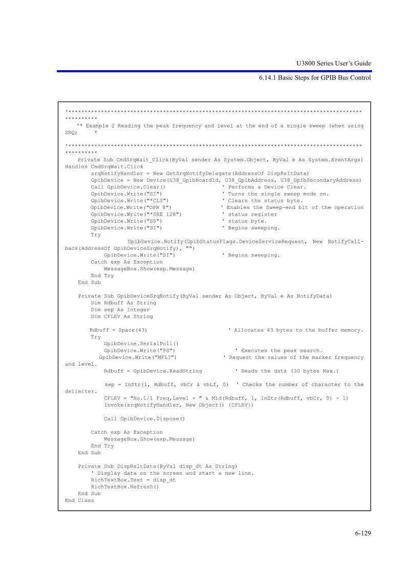
U3800 Series User’s Guide
6.14.1 Basic Steps for GPIB Bus Control
6-129
'**************************************************************************************************** '* Example 2 Reading the peak frequency and level at the end of a single sweep (when usingSRQ) *
'**************************************************************************************************** Private Sub CmdSrqWait_Click(ByVal sender As System.Object, ByVal e As System.EventArgs)Handles CmdSrqWait.Click srqNotifyHandler = New GetSrqNotifyDelegate(AddressOf DispRsltData) GpibDevice = New Device(U38_GpibBoardId, U38_GpibAddress, U38_GpibSecondaryAddress) Call GpibDevice.Clear() ' Performs a Device Clear. GpibDevice.Write("SI") ' Turns the single sweep mode on. GpibDevice.Write("*CLS") ' Clears the status byte. GpibDevice.Write("OPR 8") ' Enables the Sweep-end bit of the operation GpibDevice.Write("*SRE 128") ' status register GpibDevice.Write("S0") ' status byte. GpibDevice.Write("SI") ' Begins sweeping. Try GpibDevice.Notify(GpibStatusFlags.DeviceServiceRequest, New NotifyCall-back(AddressOf GpibDeviceSrqNotify), "") GpibDevice.Write("SI") ' Begins sweeping. Catch exp As Exception MessageBox.Show(exp.Message) End Try End Sub
Private Sub GpibDeviceSrqNotify(ByVal sender As Object, ByVal e As NotifyData) Dim Rdbuff As String Dim sep As Integer Dim CFLEV As String
Rdbuff = Space(43) ' Allocates 43 bytes to the buffer memory. Try GpibDevice.SerialPoll() GpibDevice.Write("PS") ' Executes the peak search. GpibDevice.Write("MFL?") ' Request the values of the marker frequencyand level. Rdbuff = GpibDevice.ReadString ' Reads the data (30 bytes Max.)
sep = InStr(1, Rdbuff, vbCr & vbLf, 0) ' Checks the number of character to thedelimiter. CFLEV = "No.1/1 Freq,Level = " & Mid(Rdbuff, 1, InStr(Rdbuff, vbCr, 0) - 1) Invoke(srqNotifyHandler, New Object() {CFLEV})
Call GpibDevice.Dispose()
Catch exp As Exception MessageBox.Show(exp.Message) End Try End Sub
Private Sub DispRsltData(ByVal disp_dt As String) ' Display data on the screen and start a new line. RichTextBox.Text = disp_dt RichTextBox.Refresh() End SubEnd Class

U3800 Series User’s Guide
6.14.1 Basic Steps for GPIB Bus Control
6-130
6.14.1.8 Program Examples Using the LAN
Common function from example 1 to 6
Visual Basic 6.0
'****************************************************************************' Function name' SendDtFunc' Argument' dt : transmission command. (string)' Explanation' The transmission command of argument is transmitted to U3800 by TCP/IP.' Return value' 0 : Normal' 0 Excluding: Error number'****************************************************************************Private Function SendDtFunc(dt As String) As Integer Dim ipErr As Long SendDtFunc = 0 On Error GoTo ErrOcc ipErr = 0 Me.tcpClient.SendData dt + vbLf If ipErr <> 0 Then SendDtFunc = 1 Exit Function End If Exit Function
ErrOcc: ipErr = Err.Number Resume Next
End Function
'***********************************************************' Function name' ReceiveFunc' Argument' dt : Receive data. (string)' Explanation' It receive it from R3800 by TCP/IP in the argument.' Return value' 0 : Normal' 0 Excluding: Error number'***********************************************************

U3800 Series User’s Guide
6.14.1 Basic Steps for GPIB Bus Control
6-131
Private Function ReceiveFunc(ByRef dt As String) As Integer Dim ipErr As Long ReceiveFunc = 0 ipErr = 0 On Error GoTo ErrRecv Do While (Me.tcpClient.BytesReceived = 0) DoEvents Loop Me.tcpClient.GetData dt Exit Function
ErrRecv: ipErr = Err.Number ReceiveFunc = ipErr Resume Next
End Function
Private Sub Form_Unload(Cancel As Integer) Dim ErrRet As Integer If tcpClient.State = sckClosed Then Exit Sub ErrRet = SendDtFunc("GTL" & vbLf) tcpClient.CloseEnd Sub

U3800 Series User’s Guide
6.14.1 Basic Steps for GPIB Bus Control
6-132
Microsoft Visual Basic 2008
Imports System.Net.Sockets
Public Class frmManualSample_xx Private client As TcpClient
'**************************************************************************** ' Function name ' SendDtFunc ' Argument ' dt : transmission command. (string) ' Explanation ' The transmission command of argument is transmitted to U3800 by TCP/IP. ' Return value ' 0 : Normal ' 0 Excluding: Error number '**************************************************************************** Public Function SendDtFunc(ByVal dt As String) As Integer Try Dim stream As NetworkStream = client.GetStream() Dim send_buf() As Byte = System.Text.Encoding.ASCII.GetBytes(dt + ControlChars.CrLf+ ControlChars.CrLf) stream.Write(send_buf, 0, send_buf.Length) SendDtFunc = 0 Catch ex As Exception SendDtFunc = 1 End Try End Function
'**************************************************************************** ' Function name ' ReceiveFunc ' Argument ' dt : Receive data. (string) ' Explanation ' It receive it from U3800 by TCP/IP in the argument. ' Return value ' 0 : Normal ' 0 Excluding: Error number '**************************************************************************** Public Function ReceiveFunc(ByRef dt As String) As Integer Dim n As Integer Try Dim stream As NetworkStream = client.GetStream() Dim read_buf(4006) As Byte n = stream.Read(read_buf, 0, read_buf.Length) dt = System.Text.Encoding.Default.GetString(read_buf) ReceiveFunc = 0 Catch ex As Exception ReceiveFunc = 1 End Try End Function

U3800 Series User’s Guide
6.14.1 Basic Steps for GPIB Bus Control
6-133
'**************************************************************************** ' Function name ' QeryCmdFunc ' Argument ' dt : transmission command (character string) ' QryDt : Receive data area to transmission command (character string) ' Explanation ' The transmission command of argument is transmitted to U3800 by TCP/IP. ' The data reply to QryDt is stored and returned. ' Return value ' 0 : Normal ' 0 Excluding: Error number '**************************************************************************** Public Function QeryCmdFunc(ByVal dt As String, ByRef QryDt As String) As Integer Dim n As Integer Try Dim stream As NetworkStream = client.GetStream() Dim send_buf() As Byte = System.Text.Encoding.ASCII.GetBytes(dt + ControlChars.CrLf+ ControlChars.CrLf) stream.Write(send_buf, 0, send_buf.Length) Dim read_buf(4006) As Byte n = stream.Read(read_buf, 0, read_buf.Length) QryDt = System.Text.Encoding.Default.GetString(read_buf) n = InStr(QryDt, vbCr, vbBinaryCompare) QryDt = Mid(QryDt, 1, n) QeryCmdFunc = 0 Catch ex As Exception QeryCmdFunc = 1 End Try
End Function
Private Sub frmManualSample_xx_Disposed(ByVal sender As Object, ByVal e As System.Even-tArgs) Handles Me.Disposed If client.Connected = True Then client.Close() End If End Sub
Private Sub frmManualSample_xx_Load(ByVal sender As Object, ByVal e As System.EventArgs)Handles Me.Load client = New TcpClient End SubEnd Class

U3800 Series User’s Guide
6.14.1 Basic Steps for GPIB Bus Control
6-134
Example 1 Connection LAN Interface
Visual Basic 6.0
Microsoft Visual Basic 2008
'***************************************'* Example 1 Connection LAN Interface. *'***************************************Private Sub CmdLanConnect_Click() Dim Ini As String Dim ErrRet As Integer tcpClient.RemoteHost = "192.168.0.1" ' Sets IP Address of U38 tcpClient.Protocol = sckTCPProtocol ' Sets protocol to TCP tcpClient.RemotePort = 5025 ' Sets port no. 5025 of U38 tcpClient.Connect ' Connects to U3800 port Do While (tcpClient.BytesReceived = 0) ' Waits connection DoEvents Loop tcpClient.GetData Ini ErrRet = SendDtFunc("REN" & vbLf) ' Remote enableEnd Sub
Public Class frmManualSample_01 Private client As TcpClient '*************************************** '* Example 1 Connection LAN Interface. * '*************************************** Private Sub CmdLanConnect_Click(ByVal sender As System.Object, ByVal e As System.Even-tArgs) Handles CmdLanConnect.Click client.Connect("192.168.0.1", "5025") ' Sets IP Address and port no. "5025"of U38 Dim steam As NetworkStream = client.GetStream() ' TCP Connects to U3800 port Dim read_buf(1000) As Byte Dim intRtn As Integer
steam.Read(read_buf, 0, read_buf.Length) intRtn = SendDtFunc("REN") ' Remote enable End SubEnd Class

U3800 Series User’s Guide
6.14.1 Basic Steps for GPIB Bus Control
6-135
Example 2 Initialize U3800
Visual Basic 6.0
'*******************************'* Example 2 Initialize U3800. *'*******************************Private Sub CmdInitialize_Click() Dim Ini As String Dim ErrRet As Integer tcpClient.RemoteHost = "192.168.0.1" ' Sets IP Address of U38 tcpClient.Protocol = sckTCPProtocol ' Sets protocol to TCP tcpClient.RemotePort = 5025 ' Sets port no. 5025 of U38 tcpClient.Connect ' Connects to U3800 port Do While (tcpClient.BytesReceived = 0) ' Waits connection DoEvents Loop tcpClient.GetData Ini ErrRet = SendDtFunc("REN" & vbLf) ' Remote enable Call InitU38 ' Initialize U3800 End Sub
Public Sub InitU38() Dim ErrRet As Integer ErrRet = SendDtFunc("*CLS" & vbLf) ' Resets status register ErrRet = SendDtFunc("*RST" & vbLf) ' Resets this instrumentEnd Sub

U3800 Series User’s Guide
6.14.1 Basic Steps for GPIB Bus Control
6-136
Microsoft Visual Basic 2008
Public Class frmManualSample_02 Private client As TcpClient
'******************************* '* Example 2 Initialize U3800. * '******************************* Private Sub CmdInitialize_Click(ByVal sender As System.Object, ByVal e As System.Even-tArgs) Handles CmdInitialize.Click client.Connect("192.168.0.1", "5025") ' Sets IP Address and port no. "5025"of U38 Dim steam As NetworkStream = client.GetStream() ' TCP Connects to U3800 port Dim read_buf(1000) As Byte Dim intRtn As Integer
steam.Read(read_buf, 0, read_buf.Length) intRtn = SendDtFunc("REN") ' Remote enable
Call InitU38() ' Initialize U3800 End Sub
Public Sub InitU38() Dim intRtn As Integer
intRtn = SendDtFunc("*CLS") ' Resets status register intRtn = SendDtFunc("*RST") ' Resets this instrument End SubEnd Class
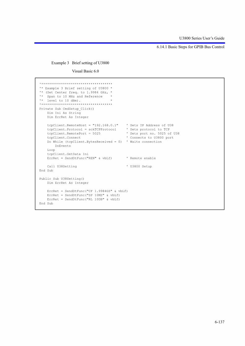
U3800 Series User’s Guide
6.14.1 Basic Steps for GPIB Bus Control
6-137
Example 3 Brief setting of U3800
Visual Basic 6.0
'************************************'* Example 3 Brief setting of U3800 *'* (Set Center freq. to 1.9984 GHz, *'* Span to 10 MHz and Reference *'* level to 10 dBm). *'************************************Private Sub CmdSetup_Click() Dim Ini As String Dim ErrRet As Integer tcpClient.RemoteHost = "192.168.0.1" ' Sets IP Address of U38 tcpClient.Protocol = sckTCPProtocol ' Sets protocol to TCP tcpClient.RemotePort = 5025 ' Sets port no. 5025 of U38 tcpClient.Connect ' Connects to U3800 port Do While (tcpClient.BytesReceived = 0) ' Waits connection DoEvents Loop tcpClient.GetData Ini ErrRet = SendDtFunc("REN" & vbLf) ' Remote enable Call U38Setting ' U3800 SetupEnd Sub
Public Sub U38Setting() Dim ErrRet As Integer ErrRet = SendDtFunc("CF 1.9984GZ" & vbLf) ErrRet = SendDtFunc("SP 10MZ" & vbLf) ErrRet = SendDtFunc("RL 10DB" & vbLf)End Sub

U3800 Series User’s Guide
6.14.1 Basic Steps for GPIB Bus Control
6-138
Microsoft Visual Basic 2008
Public Class frmManualSample_03 Private client As TcpClient
'************************************ '* Example 3 Brief setting of U3800 * '* (Set Center freq. to 1.9984 GHz, * '* Span to 10 MHz and Reference * '* level to 10 dBm). * '************************************ Private Sub CmdSetup_Click(ByVal sender As System.Object, ByVal e As System.EventArgs)Handles CmdSetup.Click client.Connect("192.168.0.1", "5025") ' Sets IP Address and port no. "5025"of U38 Dim steam As NetworkStream = client.GetStream() ' TCP Connects to U3800 port Dim read_buf(1000) As Byte Dim intRtn As Integer
steam.Read(read_buf, 0, read_buf.Length) intRtn = SendDtFunc("REN") ' Remote enable
Call U38Setting() ' U3800 Setup End Sub
Public Sub U38Setting() Dim intRtn As Integer
intRtn = SendDtFunc("CF 1.9984 GZ") intRtn = SendDtFunc("SP 10MZ") intRtn = SendDtFunc("RL 10DB") End SubEnd Classc

U3800 Series User’s Guide
6.14.1 Basic Steps for GPIB Bus Control
6-139
Example 4 Read the setting value of U3800
Visual Basic 6.0
'*********************************************'* Example 4 Read the setting value of U3800 *'*********************************************Private Sub CmdRead_Click() Dim Ini As String Dim ErrRet As Integer Dim CF As String Dim SP As String CF = Space(20) ' Prepares the text variable for read SP = Space(20) ' Prepares the text variable for read tcpClient.RemoteHost = "192.168.0.1" ' Sets IP Address of U38 tcpClient.Protocol = sckTCPProtocol ' Sets protocol to TCP tcpClient.RemotePort = 5025 ' Sets port no. 5025 of U38 tcpClient.Connect ' Connects to U3800 port Do While (tcpClient.BytesReceived = 0) ' Waits connection DoEvents Loop tcpClient.GetData Ini ErrRet = SendDtFunc("REN" & vbLf) ' Remote enable Call ReadU38Setting(CF, SP) ' Read U3800 Label.Caption = "Center freq.: " & CF & "Span freq.: " & SPEnd Sub
Public Sub ReadU38Setting(ByRef CF As String, ByRef SP As String) Dim ErrRet As Integer ErrRet = SendDtFunc("CF?" & vbLf) ' Reads request of center freq. ErrRet = ReceiveFunc(CF) ' Reads setting value ErrRet = SendDtFunc("SP?" & vbLf) ' Reads request of span freq. ErrRet = ReceiveFunc(SP) ' Reads setting valueEnd Sub

U3800 Series User’s Guide
6.14.1 Basic Steps for GPIB Bus Control
6-140
Microsoft Visual Basic 2008
Public Class frmManualSample_04 Private client As TcpClient
'********************************************* '* Example 4 Read the setting value of U3800 * '********************************************* Private Sub CmdRead_Click(ByVal sender As System.Object, ByVal e As System.EventArgs)Handles CmdRead.Click client.Connect("192.168.0.1", "5025") ' Sets IP Address and port no. "5025"of U38 Dim steam As NetworkStream = client.GetStream() ' TCP Connects to U3800 port Dim read_buf(1000) As Byte Dim intRtn As Integer Dim CF As String = Space(20) Dim SP As String = Space(20)
steam.Read(read_buf, 0, read_buf.Length) intRtn = SendDtFunc("REN") ' Remote enable
Call ReadU38Setting(CF, SP) ' Read U3800 Label.Text = "Center freq. = " & CF & "Span freq. = " & SP End Sub
Public Sub ReadU38Setting(ByRef CF As String, ByRef SP As String) Dim intRtn As Integer
intRtn = QeryCmdFunc("CF?", CF) ' Reads request of center freq. intRtn = QeryCmdFunc("SP?", SP) ' Reads request of span freq. End SubEnd Class

U3800 Series User’s Guide
6.14.1 Basic Steps for GPIB Bus Control
6-141
Example 5 Read signal level using the marker function
Visual Basic 6.0
'*********************************************************'* Example 5 Read signal level using the marker function *'*********************************************************Private Sub CmdMarkerRead_Click() Dim Ini As String Dim ErrRet As Integer Dim MKFreq As String Dim MKLevel As String MKFreq = Space(20) ' Prepares the text variable for read MKLevel = Space(20) ' Prepares the text variable for read tcpClient.RemoteHost = "192.168.0.1" ' Sets IP Address of U38 tcpClient.Protocol = sckTCPProtocol ' Sets protocol to TCP tcpClient.RemotePort = 5025 ' Sets port no. 5025 of U38 tcpClient.Connect ' Connects to U3800 port Do While (tcpClient.BytesReceived = 0) ' Waits connection DoEvents Loop tcpClient.GetData Ini ErrRet = SendDtFunc("REN" & vbLf) ' Remote enable Call ReadMkrSignal(MKFreq, MKLevel) ' Read U3800 Label.Caption = "Marker freq.: " & MKFreq & "Level: " & MKLevelEnd Sub
Public Sub ReadMkrSignal(ByRef MKFreq As String, ByRef MKLevel As String) Dim ErrRet As Integer ErrRet = SendDtFunc("MLN ON" & vbLf) ' Turns on the marker ErrRet = SendDtFunc("PS" & vbLf) ' Searches peak point of signal ErrRet = SendDtFunc("MF?" & vbLf) ' Query the marker frequency ErrRet = ReceiveFunc(MKFreq) ' Reads marker frequency ErrRet = SendDtFunc("ML?" & vbLf) ' Query the marker level ErrRet = ReceiveFunc(MKLevel) ' Reads marker levelEnd Sub

U3800 Series User’s Guide
6.14.1 Basic Steps for GPIB Bus Control
6-142
Microsoft Visual Basic 2008
Public Class frmManualSample_05 Private client As TcpClient
'********************************************************* '* Example 5 Read signal level using the marker function * '********************************************************* Private Sub CmdMarkerRead_Click(ByVal sender As System.Object, ByVal e As System.Even-tArgs) Handles CmdMarkerRead.Click client.Connect("192.168.0.1", "5025") ' Sets IP Address and port no. "5025"of U38 Dim steam As NetworkStream = client.GetStream() ' TCP Connects to U3800 port Dim read_buf(1000) As Byte Dim intRtn As Integer Dim MKFreq As String = Space(20) Dim MKLevel As String = Space(20)
steam.Read(read_buf, 0, read_buf.Length) intRtn = SendDtFunc("REN") ' Remote enable
Call ReadU38Signal(MKFreq, MKLevel) ' Read U3800 Label.Text = "Marker freq.: " & MKFreq & "Level : " & MKLevel End Sub
Public Sub ReadU38Signal(ByRef MKFreq As String, ByRef MKLevel As String) Dim intRtn As Integer
intRtn = SendDtFunc("MLN ON") ' Turns on the marker intRtn = SendDtFunc("PS") ' Searches peak point of signal intRtn = QeryCmdFunc("MF?", MKFreq) ' Query the marker frequency and Reads markerfrequency intRtn = QeryCmdFunc("ML?", MKLevel) ' Query the marker level and Reads marker level End SubEnd Class

U3800 Series User’s Guide
6.14.1 Basic Steps for GPIB Bus Control
6-143
Example 6 Measure Adjacent Channel Power
Visual Basic 6.0
'********************************************'* Example 6 Measure Adjacent Channel Power *'********************************************Private Declare Sub Sleep Lib "KERNEL32.DLL" (ByVal dwMilliseconds As Long)Private Sub CmdAcpRead_Click() Dim Ini As String Dim ErrRet As Integer Dim ResultACP As String ResultACP = Space(200) ' Prepares the text variable for read tcpClient.RemoteHost = "192.168.0.1" ' Sets IP Address of U38 tcpClient.Protocol = sckTCPProtocol ' Sets protocol to TCP tcpClient.RemotePort = 5025 ' Sets port no. 5025 of U38 tcpClient.Connect ' Connects to U3800 port Do While (tcpClient.BytesReceived = 0) ' Waits connection DoEvents Loop tcpClient.GetData Ini ErrRet = SendDtFunc("REN" & vbLf) ' Remote enable Call MeasACP(ResultACP) ' Read U3800 Label.Caption = "ACP results : " & ResultACP
End Sub
Public Sub MeasACP(ByRef ResultACP As String) Dim ErrRet As Integer Dim stb As String ErrRet = SendDtFunc("CF 2GZ" & vbLf) ' Sets carrier freq. ErrRet = SendDtFunc("SP 25MZ" & vbLf) ErrRet = SendDtFunc("CSBSDEL" & vbLf) ' Clears Channel Space param. ErrRet = SendDtFunc("ACPSCR CARR" & vbLf) ' Sets ACP mode to Carrier ErrRet = SendDtFunc("CARRBS 3.84MHz" & vbLf) ' Sets Channel Bandwidth ErrRet = SendDtFunc("CSBSIN 5MZ,3.84MZ" & vbLf) ' Adj. Channel param. ErrRet = SendDtFunc("CSBSIN 10MZ,3.84MZ" & vbLf) ' Adj. Channel param. ErrRet = SendDtFunc("ACPNQST ON" & vbLf) ' Sets Nyq. Filter operation to on ErrRet = SendDtFunc("SYMRT 3.84MZ" & vbLf) ' Sets Symbol rate of filter ErrRet = SendDtFunc("RFACT 0.22" & vbLf) ' Sets Roll off factor of filter ErrRet = SendDtFunc("ACPTM 10" & vbLf) ' Sets average times ErrRet = SendDtFunc("PMEASAVG ON" & vbLf) ' Sets average func. to ON ErrRet = SendDtFunc("ACP" & vbLf) ' Starts measurement ErrRet = SendDtFunc("*CLS;OPR 16;*SRE 128" & vbLf) ' Sets status byte stb = Space(10) Do ErrRet = SendDtFunc("*STB?" + vbLf) ErrRet = ReceiveFunc(stb) If CLng(Val(stb)) And 128 Then Exit Do Loop ErrRet = SendDtFunc("ACP?" + vbLf) Call Sleep(500) ErrRet = ReceiveFunc(ResultACP) ' Reads out all meas. results of ACPEnd Sub

U3800 Series User’s Guide
6.14.1 Basic Steps for GPIB Bus Control
6-144
Microsoft Visual Basic 2008
Public Class frmManualSample_06 Private client As TcpClient '******************************************** '* Example 6 Measure Adjacent Channel Power * '******************************************** Private Sub CmdAcpRead_Click(ByVal sender As System.Object, ByVal e As System.EventArgs)Handles CmdAcpRead.Click client.Connect("192.168.0.1", "5025") ' Sets IP Address and port no. "5025"of U38 Dim steam As NetworkStream = client.GetStream() ' TCP Connects to U3800 port Dim read_buf(1000) As Byte Dim intRtn As Integer Dim ResultACP As String = Space(200)
steam.Read(read_buf, 0, read_buf.Length) intRtn = SendDtFunc("REN") ' Remote enable
Call MeasACP(ResultACP) ' Read U3800 RichTextBox.Text = "ACP result : " & ResultACP End Sub
Public Sub MeasACP(ByRef ResultACP As String) Dim intRtn As Integer Dim stb As String = Space(3)
intRtn = SendDtFunc("CF 2GZ") ' Sets carrier freq. intRtn = SendDtFunc("SP 25MZ") intRtn = SendDtFunc("CSBSDEL") ' Clears Channel Space param. intRtn = SendDtFunc("ACPSCR CARR") ' Sets ACP mode to Carrier intRtn = SendDtFunc("CARRBS 3.84MHz") ' Sets Channel Bandwidth intRtn = SendDtFunc("CSBSIN 5MZ,3.84MZ") ' Adj. Channel param. intRtn = SendDtFunc("CSBSIN 10MZ,3.84MZ") ' Adj. Channel param. intRtn = SendDtFunc("ACPNQST ON") ' Sets Nyq. Filter operation to on intRtn = SendDtFunc("SYMRT 3.84MZ") ' Sets Symbol rate of filter intRtn = SendDtFunc("RFACT 0.22") ' Sets Roll off factor of filter intRtn = SendDtFunc("ACPTM 10") ' Sets average times intRtn = SendDtFunc("PMEASAVG ON") ' Sets average func. to ON intRtn = SendDtFunc("ACP") ' Starts measurement intRtn = SendDtFunc("*CLS;OPR 16;*SRE 128") ' Sets status byte stb = Space(10) Do intRtn = QeryCmdFunc("*STB?", stb) If CLng(Val(stb)) And 128 Then Exit Do Loop intRtn = SendDtFunc("ACP?") System.Threading.Thread.Sleep(500) intRtn = ReceiveFunc(ResultACP) ' Reads out all meas. results of ACP End SubEnd Class

U3800 Series User’s Guide
6.14.2 Example Program for Correcting Multiple Points Using External Signal Source
6-145
6.14.2 Example Program for Correcting Multiple Points Using External Signal Source
This section describes a program flow for remote control used to correct multiple points using an externalsignal source.
The following shows a flowchart of the remote control program used to perform Specific Span correction:
Specific Span Correction
idx > max?
user abort?
VCorr Abort VCFSEXTABORT
Return signal source VCSIGSRC INT
yes
yes
no
no
Set signal source VCSIGSRC EXT
Specific Vcorr Initialize VCFSEXTINIT
max Read number of steps VCFSEXTSTPSZ?
Initialize idx. idx = 1
Set index VCFSEXTIDX *
cf Read CF value (CF?).
Set cf to SigGen
Capture data for single frequency VCFSEXTEXE
Count up idx
VCorr post process VCFSEXTFINISH

U3800 Series User’s Guide
6.14.2 Example Program for Correcting Multiple Points Using External Signal Source
6-146
The following shows a flowchart of the remote control program used to perform Inband correction:
Inband Correction
idx > max?
user abort?
VCorr Abort VCINBEXTABORT
yes
yes
no
no
Set signal source VCSIGSRC EXT
Initialize idx. idx = 1
cf Read CF value (CF?). Set cf to SigGen
Inband Vcorr Initialize VCINBEXTINIT
max Read number of steps VCINBEXTSTPSZ?
Set index VCINBEXTIDX *
FOfs Read offset value VCINBEXTFO?
Set cf+FOfs to SigGen
Count up idx
Capture data for single frequency VCINBEXTEXE
Return signal source VCSIGSRC INT
VCorr post process VCINBEXTFINISH

U3800 Series User’s Guide
6.14.2 Example Program for Correcting Multiple Points Using External Signal Source
6-147
Examples 1 and 2 show GPIB and LAN versions of the program that contain these two correction func-tions.
The sample program can be downloaded from http://www.advantest.co.jp/products/emi/index.shtml.
Example 1 Multiple-points correction program GPIB version
• Required instruments
E8257D (by Agilent) PSG analog signal generator 250kHz to 50GHz
• GPIB evaluation environment
PC
Microsoft Windows XP SP3 (32bit)
Professional Ver 2002 (Japanese)
GPIB I/F
National Instruments GPIB Interfaces board
GPIB control API DLL
gpib-32.dll
File version 2.5.2.49159
GPIB API Shell
Development language
Microsoft Visual Basic 6.0(SP6)
'***********************************************************'* U3800 External SG Vector Correction Start *'* *'* GPIB I/F *'* National Instruments GPIB Interfaces *'* *'* E8257D (Agilent) PSG Analog Signal Generator *'* GPIB (SCIPI) Command *'* SG_OUTPUT__CMD = "OUTP " *'* SG_OUT_ON__CMD = "ON" *'* SG_OUT_OFF_CMD = "OFF" *'* SG_OUT_LVL_CMD = "SOUR:POW " *'* SG_OUT_LVL_UNT = "DBM" *'* SG_SET_FRQ_CMD = "SOUR:FREQ " *'* SG_SET_FRQ_UNT = "HZ" *'* *'***********************************************************

U3800 Series User’s Guide
6.14.2 Example Program for Correcting Multiple Points Using External Signal Source
6-148
Private Sub CmdVCorrStart_Click() Dim err As Long Dim i As Long Dim buf As String Dim VCorr_TtlCnt As Long Dim strVCorr_TtlCnt As String Dim CentFreq As Double Dim OfstFreq As Double Dim strFreq As String Lbl_SG_Start_Freq.Caption = "" Lbl_SG_Step_Freq.Caption = "" Lbl_SG_End_Freq.Caption = "" Lbl_SG_Current_Freq.Caption = "" Lbl_Count.Caption = "/" Call GetSetting ' U3800 & SG Setting acquisition of a Textbox. '*** GPIB **** GpibConnect = True If U38_GpibAddress > -1 And SG_GpibAddress > -1 _ And (U38_GpibAddress <> SG_GpibAddress) Then
If OpenGpib(U38_GpibAddress) < 0 Then err = MsgBox("Can't open the GPIB address(" & CStr(U38_GpibAddress) & ").", _ vbOKOnly) GpibConnect = False End If If OpenGpib(SG_GpibAddress) < 0 Then err = MsgBox("Can't open the GPIB address(" & CStr(SG_GpibAddress) & ").", _ vbOKOnly) GpibConnect = False End If End If If GpibConnect = False Then Exit Sub err = PutGpib(U38_GpibAddress, "RFE") 'RefClk=External err = PutGpib(U38_GpibAddress, "VCSIGSRC EXT") 'SigSrc EXT err = QryGpib(U38_GpibAddress, "CF?", buf) If err < 0 Then err = MsgBox("CF? query command error.", vbOKOnly) GoTo GpibOffline End If CentFreq = CDbl(buf) strFreq = CStr(CentFreq) Lbl_SG_Current_Freq.Caption = strFreq err = PutGpib(SG_GpibAddress, SG_SET_FRQ_CMD & strFreq & SG_SET_FRQ_UNT) Lbl_SG_Start_Freq.Caption = buf

U3800 Series User’s Guide
6.14.2 Example Program for Correcting Multiple Points Using External Signal Source
6-149
'Set SG output on err = PutGpib(SG_GpibAddress, SG_OUT_ON__CMD) 'Set SG output level err = PutGpib(SG_GpibAddress, SG_OUT_LVL_CMD & CStr(SG_OutputLevel) & SG_OUT_LVL_UNT) Call Sleep(500) VCorrAbort = False If Me.Opt_VCorr_Type1.value = True Then '*** Specific Span *** 'Xmath 1.Power Ratio Phase Diff Execute ON/OFF err = QryGpib(U38_GpibAddress, "XPRPDON?", buf): i = CLng(buf) 'Xmath 2.Differential Execute ON/OFF err = QryGpib(U38_GpibAddress, "XDIFFON?", buf): i = i + CLng(buf) 'Xmath 4.Power Math Execute ON/OFF err = QryGpib(U38_GpibAddress, "XMATHON?", buf): i = i + CLng(buf) If i = 0 Then err = MsgBox("Xmath Function OFF.", vbOKOnly) GoTo GpibOffline End If
err = PutGpib(U38_GpibAddress, "VCFSEXTINIT") 'Initialize Specific Span 'external SG 'vector correction. err = QryGpib(U38_GpibAddress, "VCFSEXTSTPSZ?", buf) 'Get Specific Span external 'SG vector correction 'total count. If err < 0 Then err = MsgBox("VCFSEXTSTPSZ? query command error.", vbOKOnly) Exit Sub End If VCorr_TtlCnt = CLng(buf) 'External SG vector correction 'total count. strVCorr_TtlCnt = CStr(VCorr_TtlCnt) err = QryGpib(U38_GpibAddress, "VCFA?", buf) 'Start Freq. CentFreq = CDbl(buf) strFreq = CStr(CentFreq) err = PutGpib(SG_GpibAddress, SG_SET_FRQ_CMD & strFreq & SG_SET_FRQ_UNT) Call Sleep(1000) Lbl_SG_Start_Freq.Caption = buf err = QryGpib(U38_GpibAddress, "VCFB?", buf) 'Stop Freq. Lbl_SG_End_Freq.Caption = buf err = QryGpib(U38_GpibAddress, "VCFSTEP?", buf) 'Step Freq. Lbl_SG_Step_Freq.Caption = buf Lbl_Count.Caption = "0/" & strVCorr_TtlCnt Lbl_Count.Refresh

U3800 Series User’s Guide
6.14.2 Example Program for Correcting Multiple Points Using External Signal Source
6-150
For i = 1 To VCorr_TtlCnt If VCorrAbort = True Then Exit For err = PutGpib(U38_GpibAddress, "VCFSEXTIDX " & CStr(i)) err = QryGpib(U38_GpibAddress, "CF?", buf) CentFreq = CDbl(buf) strFreq = CStr(CentFreq) Lbl_SG_Current_Freq.Caption = strFreq err = PutGpib(SG_GpibAddress, SG_SET_FRQ_CMD & strFreq & SG_SET_FRQ_UNT) Call Sleep(1000) err = PutGpib(U38_GpibAddress, "VCFSEXTEXE") Lbl_Count.Caption = CStr(i) & " / " & strVCorr_TtlCnt DoEvents Next i
If VCorrAbort = False Then err = PutGpib(U38_GpibAddress, "VCFSEXTFINISH") 'End Specific Span 'vector correction. Else err = PutGpib(U38_GpibAddress, "VCFSEXTABORT") 'Abort Specific Span 'vector correction. err = PutGpib(U38_GpibAddress, "VCSIGSRC INT") 'SigSrc INT End If Else '*** InBand *** err = PutGpib(U38_GpibAddress, "VCINBEXTINIT") 'Initialize InBand external 'SG vector correction. err = QryGpib(U38_GpibAddress, "VCINBEXTSTPSZ?", buf) 'Get InBand external SG 'vector correction 'total count. If err < 0 Then err = MsgBox("VCINBEXTSTPSZ? query command error.", vbOKOnly) Exit Sub End If VCorr_TtlCnt = CLng(buf) 'External SG vector correction total count. strVCorr_TtlCnt = CStr(VCorr_TtlCnt) Lbl_Count.Caption = "0/" & strVCorr_TtlCnt Lbl_Count.Refresh For i = 1 To VCorr_TtlCnt If VCorrAbort = True Then Exit For err = PutGpib(U38_GpibAddress, "VCINBEXTIDX " & CStr(i)) err = QryGpib(U38_GpibAddress, "VCINBEXTFO?", buf) OfstFreq = CDbl(buf) err = QryGpib(U38_GpibAddress, "CF?", buf) CentFreq = CDbl(buf) strFreq = CStr(CentFreq + OfstFreq) Lbl_SG_Current_Freq.Caption = strFreq err = PutGpib(SG_GpibAddress, SG_SET_FRQ_CMD & strFreq & SG_SET_FRQ_UNT) Call Sleep(1000) err = PutGpib(U38_GpibAddress, "VCINBEXTEXE") Lbl_Count.Caption = CStr(i) & " / " & strVCorr_TtlCnt DoEvents Next i

U3800 Series User’s Guide
6.14.2 Example Program for Correcting Multiple Points Using External Signal Source
6-151
If VCorrAbort = False Then err = PutGpib(U38_GpibAddress, "VCINBEXTFINISH") 'End InBand vector 'correction. Else err = PutGpib(U38_GpibAddress, "VCINBEXTABORT") 'Abort InBand vector 'correction. err = PutGpib(U38_GpibAddress, "VCSIGSRC INT") 'SigSrc INT End If End If GpibOffline: Call CloseGpib(U38_GpibAddress) Call CloseGpib(SG_GpibAddress)
End Sub
'*********************************************'* U3800 External SG Vector Correction Abort *'*********************************************Private Sub CmdVCorrAbort_Click() VCorrAbort = TrueEnd Sub

U3800 Series User’s Guide
6.14.2 Example Program for Correcting Multiple Points Using External Signal Source
6-152
Example 2 Multiple-points correction program LAN version
• Required instruments
E8257D (by Agilent) PSG analog signal generator 250kHz to 50GHz
• LAN evaluation environment
PC
Microsoft Windows XP SP3 (32bit)
Professional Ver 2002 (Japanese)
Etherbet I/F
3Com 3C920 Integrated Fast Ethernet Controller board
TCP/IP control API DLL
wsock32.dll
File version 5.1.2600.5512
Windows Socket 32-Bit DLL
Development language
Microsoft Visual Basic 6.0(SP6)
'***********************************************************'* U3800 External SG Vector Correction Start *'* *'* Ethernet I/F *'* 3Com 3C920 Integrated Fast Ethernet Controller *'* *'* E8257D (Agilent) PSG Analog Signal Generator *'* GPIB (SCIPI) Command *'* SG_OUTPUT__CMD = "OUTP " *'* SG_OUT_ON__CMD = "ON" *'* SG_OUT_OFF_CMD = "OFF" *'* SG_OUT_LVL_CMD = "SOUR:POW " *'* SG_OUT_LVL_UNT = "DBM" *'* SG_SET_FRQ_CMD = "SOUR:FREQ " *'* SG_SET_FRQ_UNT = "HZ" *'* *'***********************************************************Private Sub CmdVCorrStart_Click() Dim err As Long Dim i As Long Dim buf As String Dim VCorr_TtlCnt As Long Dim strVCorr_TtlCnt As String Dim CentFreq As Double Dim OfstFreq As Double Dim strFreq As String

U3800 Series User’s Guide
6.14.2 Example Program for Correcting Multiple Points Using External Signal Source
6-153
Lbl_SG_Start_Freq.Caption = "" Lbl_SG_Step_Freq.Caption = "" Lbl_SG_End_Freq.Caption = "" Lbl_SG_Current_Freq.Caption = "" Lbl_Count.Caption = "/" Call GetSetting ' U3800 & SG Setting acquisition of a Textbox. '*** TCP/IP **** Call InitWinsock
TcpipConnect = True If OpenSocket(U38_SockID, str_U38_TcpipAddress, U38_PortNo) < 0 Then err = MsgBox("Can't open the TCP/IP address(" & str_U38_TcpipAddress & ").", _ vbOKOnly) TcpipConnect = False Else err = GetSocket(U38_SockID, buf) err = PutSocket(U38_SockID, "REN") End If If OpenSocket(SG_SockID, str_SG_TcpipAddress, SG_PortNo) < 0 Then err = MsgBox("Can't open the TCP/IP address(" & str_SG_TcpipAddress & ").", _ vbOKOnly) TcpipConnect = False End If If TcpipConnect = False Then Exit Sub
err = PutSocket(U38_SockID, "RFE") 'RefClk=External err = PutSocket(U38_SockID, "VCSIGSRC EXT") 'SigSrc EXT
err = QrySocket(U38_SockID, "CF?", buf) If err < 0 Then err = MsgBox("CF? query command error.", vbOKOnly) GoTo SocketClose End If CentFreq = CDbl(buf) strFreq = CStr(CentFreq) Lbl_SG_Current_Freq.Caption = strFreq err = PutSocket(SG_SockID, SG_SET_FRQ_CMD & strFreq & SG_SET_FRQ_UNT) Lbl_SG_Start_Freq.Caption = buf 'Set SG output on err = PutSocket(SG_SockID, SG_OUT_ON__CMD) 'Set SG output level err = PutSocket(SG_SockID, SG_OUT_LVL_CMD & CStr(SG_OutputLevel) & SG_OUT_LVL_UNT) Call Sleep(500) VCorrAbort = False

U3800 Series User’s Guide
6.14.2 Example Program for Correcting Multiple Points Using External Signal Source
6-154
If Me.Opt_VCorr_Type1.Value = True Then '*** Specific Span *** 'Xmath 1.Power Ratio Phase Diff Execute ON/OFF err = QrySocket(U38_SockID, "XPRPDON?", buf): i = CLng(buf) 'Xmath 2.Differential Execute ON/OFF err = QrySocket(U38_SockID, "XDIFFON?", buf): i = i + CLng(buf) 'Xmath 4.Power Math Execute ON/OFF err = QrySocket(U38_SockID, "XMATHON?", buf): i = i + CLng(buf) If i = 0 Then err = MsgBox("Xmath Function OFF.", vbOKOnly) GoTo SocketClose End If err = PutSocket(U38_SockID, "VCFSEXTINIT") 'Initialize Specific Span 'external SG vector correction. err = QrySocket(U38_SockID, "VCFSEXTSTPSZ?", buf) 'Get Specific Span external SG 'vector correction total count. If err < 0 Then err = MsgBox("VCFSEXTSTPSZ? query command error.", vbOKOnly) Exit Sub End If VCorr_TtlCnt = CLng(buf) 'External SG vector correction total count. strVCorr_TtlCnt = CStr(VCorr_TtlCnt) err = QrySocket(U38_SockID, "VCFA?", buf) 'Start Freq. CentFreq = CDbl(Trim(buf)) strFreq = CStr(CentFreq) err = PutSocket(SG_SockID, SG_SET_FRQ_CMD & strFreq & SG_SET_FRQ_UNT) Call Sleep(1000) Lbl_SG_Start_Freq.Caption = Trim(buf) err = QrySocket(U38_SockID, "VCFB?", buf) 'Stop Freq. Lbl_SG_End_Freq.Caption = Trim(buf) err = QrySocket(U38_SockID, "VCFSTEP?", buf) 'Step Freq. Lbl_SG_Step_Freq.Caption = Trim(buf) Lbl_Count.Caption = "0/" & strVCorr_TtlCnt Lbl_Count.Refresh For i = 1 To VCorr_TtlCnt If VCorrAbort = True Then Exit For err = PutSocket(U38_SockID, "VCFSEXTIDX " & CStr(i)) err = QrySocket(U38_SockID, "CF?", buf) CentFreq = CDbl(Trim(buf)) strFreq = CStr(CentFreq) Lbl_SG_Current_Freq.Caption = strFreq err = PutSocket(SG_SockID, SG_SET_FRQ_CMD & strFreq & SG_SET_FRQ_UNT) Call Sleep(1000) err = PutSocket(U38_SockID, "VCFSEXTEXE") Lbl_Count.Caption = CStr(i) & " / " & strVCorr_TtlCnt DoEvents Next i

U3800 Series User’s Guide
6.14.2 Example Program for Correcting Multiple Points Using External Signal Source
6-155
If VCorrAbort = False Then err = PutSocket(U38_SockID, "VCFSEXTFINISH") 'End Specific Span 'vector correction. Else err = PutSocket(U38_SockID, "VCFSEXTABORT") 'Abort Specific Span 'vector correction. err = PutSocket(U38_SockID, "VCSIGSRC INT") 'SigSrc INT End If Else '*** InBand *** err = PutSocket(U38_SockID, "VCINBEXTINIT") 'Initialize InBand external 'SG vector correction. err = QrySocket(U38_SockID, "VCINBEXTSTPSZ?", buf) 'Get InBand external SG 'vector correction total count. If err < 0 Then err = MsgBox("VCINBEXTSTPSZ? query command error.", vbOKOnly) Exit Sub End If VCorr_TtlCnt = CLng(buf) 'External SG vector correction total count. strVCorr_TtlCnt = CStr(VCorr_TtlCnt) Lbl_Count.Caption = "0/" & strVCorr_TtlCnt Lbl_Count.Refresh For i = 1 To VCorr_TtlCnt If VCorrAbort = True Then Exit For err = PutSocket(U38_SockID, "VCINBEXTIDX " & CStr(i)) err = QrySocket(U38_SockID, "VCINBEXTFO?", buf) OfstFreq = CDbl(Trim(buf)) err = QrySocket(U38_SockID, "CF?", buf) CentFreq = CDbl(buf) Lbl_SG_Current_Freq.Caption = strFreq strFreq = CStr(CentFreq + OfstFreq) err = PutSocket(SG_SockID, SG_SET_FRQ_CMD & strFreq & SG_SET_FRQ_UNT) Call Sleep(1000) err = PutSocket(U38_SockID, "VCINBEXTEXE") Lbl_Count.Caption = CStr(i) & " / " & strVCorr_TtlCnt DoEvents Next i
If VCorrAbort = False Then err = PutSocket(U38_SockID, "VCINBEXTFINISH") 'End InBand vector 'correction. Else err = PutSocket(U38_SockID, "VCINBEXTABORT") 'Abort InBand vector 'correction. err = PutSocket(U38_SockID, "VCSIGSRC INT") 'SigSrc INT End If End If

U3800 Series User’s Guide
6.14.2 Example Program for Correcting Multiple Points Using External Signal Source
6-156
SocketClose: Call CloseConnect(U38_SockID) Call CloseConnect(SG_SockID) Call CloseWinsock End Sub
'*********************************************'* U3800 External SG Vector Correction Abort *'*********************************************Private Sub CmdVCorrAbort_Click() VCorrAbort = TrueEnd Sub
U3800 Series User’s Guide
7. Specifications
7-1
7. Specifications
This chapter describes the specifications of this instrument.
The performance of this instrument is guaranteed under the following conditions unless otherwise specified.
• The specified calibration period must be adhered to.
• After turning on the power and warming-up for 5 minutes or more under the specified environmental conditions.
• After automatic calibration has been performed.
Reference data is provided to help you use the product efficiently, but it will not guarantee the performanceof this instrument. The data is described by using the following notation.
Specifications (spec.): Indicates the specifications within which the performance of the product can beguaranteed. Includes variations in the performance of each product, uncertaintyin calibrations, and changes in performance due to the environment.
Typical value (typ.): Indicates the average performance of the product. Excludes variations in the per-formance of each product, uncertainty in measurements, and changes in perfor-mance due to the environment.
Nominal value (nom.): Indicates the general performance of the product and does not refer to the guar-anteed performance.

U3800 Series User’s Guide
7.1 U3841 Performance Specifications
7-2
7.1 U3841 Performance Specifications
7.1.1 Frequency
7.1.2 Sweep
Description Specifications
Frequency range 9 kHz to 3 GHz
Built-in preamp 10 MHz to 3 GHz
Internal frequency reference stability
Aging rate 2 10-6/ year
Temperature stability 2.5 10-6 (0C to 50C)
Frequency span
Range Zero span, 5 kHz to full spanFrequency sweep 100 Hz to 40 MHz FFT, CBW step
Accuracy 1% of frequency span
Signal purity(When the internal frequency reference is used.)
-85 dBc/Hz, 10 kHz offset (SPAN < 200 kHz)
Resolution bandwidth (RBW)
Range 100 Hz to 3 MHz (1, 3 sequence)1 Hz to 400 kHz (FFT, CBW/100)
Accuracy 12%
Video bandwidth (VBW)Range 10 Hz to 3 MHz (1, 3 sequence)
Description Specifications
Sweep
Sweep time setting range
Zero span 50 s to 1000 s
Spectrum mode 20 ms to 1000 s
Sweep time accuracy 2% (Zero Span)
Sweep mode CONTINUOUS, SINGLE, GATE
Trigger function
Trigger source Free run, Video, IF, External

U3800 Series User’s Guide
7.1.3 Amplitude
7-3
7.1.3 Amplitude
7.1.4 Amplitude Accuracy
Description Specifications
Amplitude measurement range +30 dBm to displayed average noise level
Maximum safe input level
Average continuous power +30 dBm (Input attenuator 10 dB) Preamp Off+13 dBm (Input attenuator 0 dB) Preamp On
DC voltage 50 VDCmax
Input attenuator range 0 to 50 dB, 10 dB step
Detector mode Normal, Positive Peak, Negative Peak, Sample, RMS, Video Average
Description Specifications
Calibration signal accuracy (20 MHz)
Frequency 20 MHz
Amplitude -20 dBm
Accuracy 0.3 dB
Total level accuracy (After performing the automatic calibration, Signal level: -10 dBm, Preamp Off, Input attenuator: 10 dB, REF = 0 dBm, Tem-perature +20C to +30C)0.8 dB Frequency range 10 MHz to 3 GHz1.0 dB Frequency range 9 kHz to 3 GHz

U3800 Series User’s Guide
7.1.5 Dynamic Range
7-4
7.1.5 Dynamic Range
7.1.6 Vector Analysis
Description Specifications
Displayed average noise level Ref level < -45 dBm RBW = 100 Hz-123 dBm + 2 f (GHz)dB 10MHz < f < 2.5 GHz Preamp Off-123 dBm + 2.5 f (GHz)dB f 2.5 GHz Preamp Off-138 dBm + 3 f (GHz)dB Preamp On
1 dB gain compression Frequency range > 20 MHz> -8 dBm Preamp Off> -25 dBm Preamp On
Third order intermodulation distortion (TOI) (Frequency range > 20 MHz, Preamp Off, Mixer input level: -20 dBm, Frequency separation: 200 kHz)< -60 dBc
Image responses, Multiple responses, and Out-of-band responses
< -60 dBc, Mixer input level: -20 dBm
Residual responses (Frequency > 10 MHz, Preamp Off)< -80 dBm
Description Specifications
IQ waveform record
Measurement synchronization Trigger synchronization, phase synchronization
Measurement bandwidth (CBW) 100 Hz to 30 MHz, 1, 3 step, 40 MHz
Sampling rate 500 Hz (CBW 100 Hz) to 65 MHz (CBW 40 MHz)IQ pair data
Time resolution 15.4 ns (CBW 40 MHz) to 2 ms (CBW 100 Hz)Sampling interval
Capture time 120 ms (CBW 40 MHz) to 1000 sec (CBW 100 Hz)In each channel (channels 1 and 2)
Balance between the channels After calibration, frequency: 1 GHz, mixer input level: -30 dBm, preamp: off BW: 100 kHz/1 ms, CBW center
Amplitude 2.0dB
Phase 15deg

U3800 Series User’s Guide
7.1.7 Input and Output
7-5
7.1.7 Input and Output
Description Specifications
RF input
Connector Type-N (f) on the front panel
Impedance 50 nomVSWR Input attenuator 10 dB, 10 MHz to 3 GHz
< 1.5:1
Calibration signal output
Connector Type-N (f) on the front panel
Impedance 50 nomFrequency 20 MHz
Level -20 dBm
External trigger input
Connector BNC (f) on the rear panel
Impedance 10 k nom, DC coupling
Trigger level 0 V to +5 V
External trigger output
Connector BNC (f) on the rear panel
BNC (f) on the rear panel 3.3 V (CMOS)
Frequency reference input
Connector BNC (f) on the rear panel
Impedance 50 nomFrequency 10 MHz
Level -2 dBm to 16 dBm
Frequency reference source output
Connector BNC (f) on the rear panel
Impedance 50 (nom.)
Frequency 10 MHz
Level > 0dBm
IF output
Connector BNC (f) on the rear panel
Impedance 50 nomFrequency 21.4 MHz, 97.5 MHz (Depends on RBW and CBW)
GPIB IEEE-488 bus connector
USB-A USB1.1 on the front and rear panels
LAN RJ45 on the rear panel10/100Base-T, Protocol TCP/IP
Video out VGA (15pin f) on the rear panel
Sound out Small monophonic jack

U3800 Series User’s Guide
7.2 U3851 Performance Specifications
7-6
7.2 U3851 Performance Specifications
7.2.1 Frequency
7.2.2 Sweep
Description Specifications
Frequency range 9 kHz to 8 GHz
Frequency band 9 kHz to 3.1 GHz Band 03.0 GHz to 8 GHz Band 1
Built-in preamp 10 MHz to 8 GHz
Internal frequency reference stability
Aging rate 2 10-6/ year
Temperature stability 2.5 10-6 (0C to 50C)
Frequency span
Range Zero span, 5 kHz to full span Frequency sweep 100 Hz to 40 MHz FFT, CBW step
Accuracy 1% of frequency span
Signal purity(When the internal frequency reference is used.)
-85 dBc/Hz, 10 kHz offset (SPAN < 200 kHz)
Resolution bandwidth (RBW)
Range 100 Hz to 3 MHz (1, 3 sequence)1 Hz to 400 kHz (FFT, CBW/100)
Accuracy 12%
Video bandwidth (VBW)Range 10 Hz to 3 MHz (1, 3 sequence)
Description Specifications
Sweep
Sweep time setting range
Zero span 50 s to 1000 s
Spectrum mode 20 ms to 1000 s
Sweep time accuracy 2% (Zero Span)
Sweep mode REPEAT, SINGLE
Trigger function
Trigger source Free run, Video, IF, External

U3800 Series User’s Guide
7.2.3 Amplitude
7-7
7.2.3 Amplitude
7.2.4 Amplitude Accuracy
Description Specifications
Amplitude measurement range +30 dBm to displayed average noise level
Maximum safe input level
Average continuous power +30 dBm (Input attenuator 10 dB) Preamp Off+13 dBm (Input attenuator 10 dB) Preamp On
DC voltage 15 VDCmax
Input attenuator range 0 to 50 dB, 10 dB step
Detector mode Normal, Positive Peak, Negative Peak, Sample, RMS, Video Average
Description Specifications
Calibration signal accuracy (20 MHz)
Frequency 20 MHz
Amplitude -20 dBm
Accuracy 0.3 dB
Total level accuracy (After performing the automatic calibration, Image Suppression Off, Signal level: -10 dBm, Preamp Off, Input attenuator: 10dB, REF = 0 dBm, Temperature 20C to 30C)0.8 dB Frequency range 10 MHz to 3.1 GHz1.0 dB Frequency range 3.1 GHz to 8 GHz1.5 dB Frequency range 9 kHz to 10 MHz

U3800 Series User’s Guide
7.2.5 Dynamic Range
7-8
7.2.5 Dynamic Range
7.2.6 Vector Analysis
Description Specifications
Displayed average noise level Frequency range 10 MHz to 8 GHzRef level < -45 dBm RBW = 100 Hz-123 dBm + 2 f (GHz)dB Band 0 Preamp Off-122 dBm + 1.2 f (GHz)dB Band 1 Preamp Off-138 dBm + 3 f (GHz)dB Band 0 Preamp On-139 dBm + 1.4 f (GHz)dB Band 1 Preamp On
1 dB gain compression Frequency range 10 MHz to 8 GHz> -8 dBm Preamp Off> -25 dBm Preamp On
Third order intermodulation distortion (TOI) (Frequency range 10 MHz to 8 GHz, Preamp Off, Mixer input level: -20 dBm, Frequency separation: 200 kHz)-50 dBc
Image responses, Multiple responses, and Out-of-band responses
(Image suppression: on, mixer input level: -30 dBm)< 60 dBc
Residual responses (Frequency 10 MHz to 8 GHz)< -80 dBm Preamp Off
Description Specifications
IQ waveform record
Measurement synchronization Trigger synchronization, phase synchronization
Measurement bandwidth (CBW) 100 Hz to 30 MHz, 1, 3 step, 40 MHz
Sampling rate 500 Hz (CBW 100 Hz) to 65 MHz (CBW 40 MHz)IQ pair data
Time resolution 15.4 ns (CBW 40 MHz) to 2 ms (CBW 100 Hz)Sampling interval
Capture time 120 ms (CBW 40 MHz) to 1000 sec (CBW 100 Hz)In each channel (channels 1 and 2)
Balance between the channels After calibration, frequency: 1 GHz, mixer input level: -30 dBm, preamp: off BW: 100 kHz/1 ms, CBW center
Amplitude 2.0dB
Phase 15deg

U3800 Series User’s Guide
7.2.7 Input and Output
7-9
7.2.7 Input and Output
Description Specifications
RF input
Connector Type-N (f) on the front panel
Impedance 50 nomVSWR Input attenuator 10 dB
< 1.7:1 (10 MHz to 3 GHz)< 2.0:1 (> 3.0 GHz)
Calibration signal output
Connector Type-N (f) on the front panel
Impedance 50 nomFrequency 20 MHz
Level -20 dBm
External trigger input
Connector BNC (f) on the rear panel
Impedance 10 k nom, DC coupling
Trigger level 0 V to 5 V
External trigger output
Connector BNC (f) on the rear panel
Level 3.3 V (CMOS)
Frequency reference input
Connector BNC (f) on the rear panel
Impedance 50 nomFrequency 10 MHz
Level -2 dBm to 16 dBm
Frequency reference source output
Connector BNC (f) on the rear panel
Impedance 50 (nom.)
Frequency 10 MHz
Level > 0dBm
IF output
Connector BNC (f) on the rear panel
Impedance 50 nomFrequency 21.4 MHz, 97.5 MHz (Depends on RBW and CBW)
GPIB IEEE-488 bus connector
USB-A USB1.1 on the front and rear panels
LAN RJ45 on the rear panel10/100Base-T, Protocol TCP/IP
Video out VGA (15pin f) on the rear panel

U3800 Series User’s Guide
7.3 U3872 Performance Specifications
7-10
7.3 U3872 Performance Specifications
7.3.1 Frequency
7.3.2 Sweep
Description Specifications
Frequency range [L-Input] 9 kHz to 8 GHz
Frequency band 9 kHz to 3.1 GHz: Band 03.0 GHz to 8 GHz: Band 1
Built-in preamp 10 MHz to 8 GHz
Frequency range [H-Input] 10 MHz to 43 GHz
Frequency band 10 MHz to 3.1 GHz Band 0 (N=1)3.0 GHz to 8.0 GHz Band 1 (N=1)7.8 GHz to 14.573 GHz Band 2 (N=2)14.4288 GHz to 28.0 GHz Band 3 (N=4)27.8 GHz to 43.0 GHz Band 4 (N=6)
Internal frequency reference stability
Aging rate 2 10-6/ year
Temperature stability 2.5 10-6 (0C to 50C)
Frequency span
Range Zero span, 5 kHz to full spanFrequency sweep 100 Hz to 40 MHz FFT, CBW step
Accuracy 1% of frequency span
Signal purity(When the internal frequency reference is used.)
(-85 + 20logN) dBc/Hz, 10 kHz offset (SPAN < 200 kHz)
Resolution bandwidth (RBW)
Range 100 Hz to 3 MHz (1, 3 sequence)1 Hz to 400 kHz (FFT, CBW/100)
Accuracy 12%
Video bandwidth (VBW)
Range 10 Hz to 3 MHz (1, 3 sequence)
Description Specifications
Sweep
Sweep time setting range
Zero span 50 s to 1000 s
Spectrum mode 20 ms to 1000 s
Sweep time accuracy 2% (Zero Span)
Sweep mode REPEAT, SINGLE
Trigger function
Trigger source Free run, Video, IF, External

U3800 Series User’s Guide
7.3.3 Amplitude
7-11
7.3.3 Amplitude
7.3.4 Amplitude Accuracy
Description Specifications
Amplitude measurement range
[L-Input] Noise to +30 dBm
[H-Input] Noise to +10 dBm
Maximum safe input level
[L-Input] +30 dBm (Input attenuator 10 dB) Preamp Off+13 dBm (Input attenuator = 0 dB) Preamp On
DC voltage 15 VDCmax
[H-Input] +10 dBm (Input attenuator 0 dB)
DC voltage 25 VDCmax
Input attenuator range
[L-Input] 0 to 50 dB, 10 dB step
[H-Input] 0 to 30 dB, 10 dB step
Display range 100, 50, 20, 10, 5 dB, Linear
Scale unit dBm, dBmV, dBV, dBVemf, dBpW, W, V
Reference level setting range
[L-Input] -140 dBm to +40 dBm
[H-Input] -140 dBm to +20 dBm
Detector mode Normal, Positive Peak, Negative Peak, Sample, RMS, Video Average
Description Specifications
Calibration signal accuracy (20 MHz)
Frequency 20 MHz
Amplitude -20 dBm
Accuracy 0.3 dB
Total level accuracy (After performing the automatic calibration, Image Suppression Off, Signal level: -10 dBm to -50 dBm, Preamp Off, Input attenu-ator: 10 dB, REF = 0 dBm, Temperature 20C to 30C)
[L-Input] 0.8 dB (Band 0) Frequency 10 MHz to 3.1 GHz1 dB (Band 1) Frequency 3.1 GHz to 8 GHz1.5 dB Frequency 9 kHz to 10 MHz
[H-Input] 0.8 dB (Band 0) Frequency 10 MHz to 3.1 GHz1 dB (Band 1) Frequency 3.1 GHz to 8 GHz3.0 dB (Band 2) Frequency 7.8 GHz to 14.573 GHz3.5 dB (Band 3) Frequency 14.4288 GHz to 28.0 GHz4.5 dB (Band 4) Frequency 27.8 GHz to 43 GHz

U3800 Series User’s Guide
7.3.5 Dynamic Range
7-12
7.3.5 Dynamic Range
7.3.6 Vector Analysis
Description Specifications
Displayed average noise level Frequency range > 10 MHzRef level < -45 dBm RBW = 100 Hz
[L-Input] -123 dBm + 2 f (GHz)dB Band 0 Preamplifier Off-122 dBm + 1.2 f (GHz)dB Band 1 Preamplifier Off-138 dBm + 3 f (GHz)dB(TBD) Band 0 Preamplifier On-139 dBm + 1.4 f (GHz)dB Band 1 Preamplifier On
[H-Input] -121 dBm + 2 f (GHz)dB Band 0-120 dBm + 1.5 f (GHz)dB Band 1-111 dBm (-118 dBm typ.) Band 2-109 dBm (-117 dBm typ.) Band 3-105 dBm (-112 dBm typ.) Band 4
1 dB gain compression Frequency range > 10 MHz> -8 dBm Preamp Off> -25 dBm Preamp On
Third order intermodulation distortion (TOI) (Frequency range > 10 MHz, Preamp Off, Mixer input level: -20 dBm, 2-Signal separation:1 MHz)-50 dBc
Image responses, Multiple responses, and Out-of-band responses
(Mixer input level: -30 dBm, image suppression: on, span < 5 GHz)< -60 dBc
Residual responses (Frequency range > 10 MHz)-80 dBm Preamp Off
Description Specifications
IQ waveform record
Measurement synchronization Trigger synchronization, phase synchronization
Measurement bandwidth (CBW) 100 Hz to 30 MHz, 1, 3 step, 40 MHz
Sampling rate 500 Hz (CBW 100 Hz) to 65 MHz (CBW 40 MHz)IQ pair data
Time resolution 15.4 ns (CBW 40 MHz) to 2 ms (CBW 100 Hz)Sampling interval
Capture time 120 ms (CBW 40 MHz) to 1000 sec (CBW 100 Hz)In each channel (channels 1 and 2)
Balance between the channels After calibration, frequency: 1 GHz, mixer input level: -30 dBm, preamp: off BW: 100 kHz/1 ms, CBW center
Amplitude 2.0dB
Phase 15deg
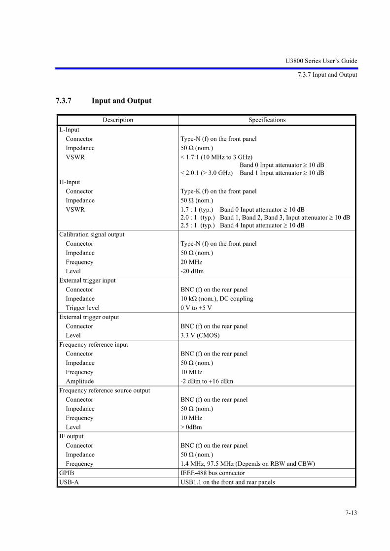
U3800 Series User’s Guide
7.3.7 Input and Output
7-13
7.3.7 Input and Output
Description Specifications
L-Input
Connector Type-N (f) on the front panel
Impedance 50 nomVSWR < 1.7:1 (10 MHz to 3 GHz)
Band 0 Input attenuator 10 dB< 2.0:1 (> 3.0 GHz) Band 1 Input attenuator 10 dB
H-Input
Connector Type-K (f) on the front panel
Impedance 50 (nom.)
VSWR 1.7 : 1 (typ.) Band 0 Input attenuator 10 dB2.0 : 1 (typ.) Band 1, Band 2, Band 3, Input attenuator 10 dB2.5 : 1 (typ.) Band 4 Input attenuator 10 dB
Calibration signal output
Connector Type-N (f) on the front panel
Impedance 50 nomFrequency 20 MHz
Level -20 dBm
External trigger input
Connector BNC (f) on the rear panel
Impedance 10 k nom, DC coupling
Trigger level 0 V to +5 V
External trigger output
Connector BNC (f) on the rear panel
Level 3.3 V (CMOS)
Frequency reference input
Connector BNC (f) on the rear panel
Impedance 50 nomFrequency 10 MHz
Amplitude -2 dBm to 16 dBm
Frequency reference source output
Connector BNC (f) on the rear panel
Impedance 50 (nom.)
Frequency 10 MHz
Level > 0dBm
IF output
Connector BNC (f) on the rear panel
Impedance 50 nomFrequency 1.4 MHz, 97.5 MHz (Depends on RBW and CBW)
GPIB IEEE-488 bus connector
USB-A USB1.1 on the front and rear panels
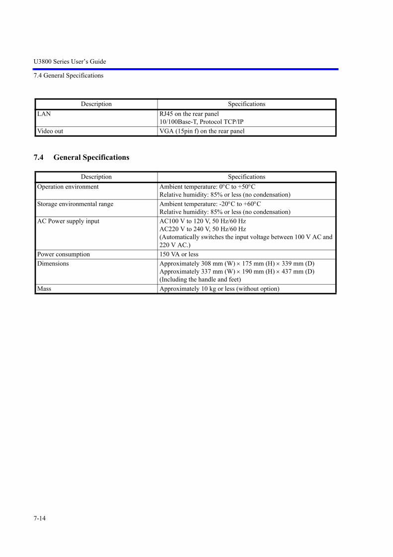
U3800 Series User’s Guide
7.4 General Specifications
7-14
7.4 General Specifications
LAN RJ45 on the rear panel10/100Base-T, Protocol TCP/IP
Video out VGA (15pin f) on the rear panel
Description Specifications
Operation environment Ambient temperature: 0C to +50CRelative humidity: 85% or less (no condensation)
Storage environmental range Ambient temperature: -20C to +60CRelative humidity: 85% or less (no condensation)
AC Power supply input AC100 V to 120 V, 50 Hz/60 HzAC220 V to 240 V, 50 Hz/60 Hz(Automatically switches the input voltage between 100 V AC and 220 V AC.)
Power consumption 150 VA or less
Dimensions Approximately 308 mm (W) 175 mm (H) 339 mm (D)Approximately 337 mm (W) 190 mm (H) 437 mm (D) (Including the handle and feet)
Mass Approximately 10 kg or less (without option)
Description Specifications

U3800 Series User’s Guide
7.5 Options
7-15
7.5 Options
7.5.1 Option 20 High Stability Frequency Reference
7.5.2 Option 28 EMC Filter
7.5.3 Option 76 3 GHz Tracking Generator
Description Specifications
Reference frequency stability
Aging rate 2 10-8/ day, 1 10-7/ year
Warm-up drift (nominal) 5 10-8 (+25C, 10 minutes after turning the power on)
Temperature drift 5 10-8 (0 to +40C, with reference to +25C)
Description Specifications
6 dB bandwidth
Range 200 Hz, 9 kHz, 120 kHz, 1 MHz
Accuracy < ±10%
Detector mode Normal, Positive peak, Negative peak, Sample, RMS, Average, QP
Description Specifications
Frequency range 100 kHz to 3 GHz
Frequency offset
Range 0 to 1 GHz
Resolution 1 kHz
Accuracy 300 Hz
Output level range -5 to -60 dBm 0.5 dB step
TG leakage -80 dBm Input attenuator: 0 dB
Output impedance 50 (nom.)
Maximum allowable input 10 dBm, 10 VDC
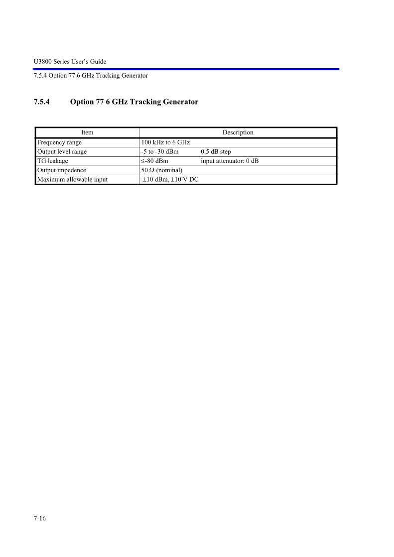
U3800 Series User’s Guide
7.5.4 Option 77 6 GHz Tracking Generator
7-16
7.5.4 Option 77 6 GHz Tracking Generator
Item Description
Frequency range 100 kHz to 6 GHz
Output level range -5 to -30 dBm 0.5 dB step
TG leakage -80 dBm input attenuator: 0 dB
Output impedence 50 (nominal)
Maximum allowable input 10 dBm, 10 V DC

U3800 Series User’s Guide
8. Options and Accessories
8-1
8. Options and Accessories
This chapter describes the options and accessories for this instrument.
8.1 Options
8.2 Accessories
Table 8-1 Options
Option Description Note
OPT20 High stability frequency reference source
OPT28 EMC filter
OPT76 Tracking generator (50 , 3 GHz)
OPT77 Tracking generator (50 , 6 GHz) Applies to the U3851 and U3872.
Table 8-2 Accessories
Name Product Code
50 / 75 converter ZT-130NC
Transit case A129003
Power divider kit (8 GHz/SMA) A199002
Power divider kit (40 GHz/K) A199003
Rack mount kit (JIS) A122004
Rack mount kit (EIA) A124005
Highpass filter (2.8 GHz to 18 GHz) A899001
Highpass filter (8 GHz to 18 GHz) A899002
Highpass filter (11 GHz to 26 GHz) A899003
Highpass filter (18 GHz to 30 GHz) A899004
VSWR bridge A199001
U3800 Series User’s Guide in Japanese (printed document)
JU3800S
U3800 Series User’s Guide in English (printed document)
EU3800S


U3800 Series User’s Guide
9. Maintenance
9-1
9. Maintenance
This chapter describes the following matters related to the maintenance of this instrument in order to maintainits designed performance.
• 9.1 Cleaning
• 9.2 About Calibration
• 9.3 About Replacement of Limited-Life Parts
• 9.4 Method of Storing the Instrument
• 9.5 Transportation
• 9.6 Notes for Requesting Repair, Replacement of Parts, and Periodic Calibration
• 9.7 List of Error Messages
• 9.8 In Case of Difficulty
• 9.9 Product Disposal and Recycle
9.1 Cleaning
This section describes how to clean this instrument and some matters to note.
WARNING: Turn off the AC power switch on the rear panel and extract the power cable from the wall socket toprotect yourself from electric shock accidents. Never attempt to remove the cabinet cover to clean the inside of the instrument.
9.1.1 Cabinet Cleaning
Use the following procedure to clean the cabinet of this instrument.
Clean the cabinet surface with a soft dry cloth.If the surface is not clean enough, try again with a cloth soaked in a weakened neutral detergent. Then wipethe surface with a soft dry cloth.
CAUTION: Do not allow water to splash into the inside of the instrument. Do not use an organic solvent such as benzene, toluene, xylene, or acetone and the cleanser forcleaning. They can cause the paint on the cabinet to come off, deform, or degrade.

U3800 Series User’s Guide
9.1.2 Cleaning of Other Parts
9-2
9.1.2 Cleaning of Other Parts
Use appropriate caution to protect this instrument from dust.
WARNING: Remove dust periodically from wall sockets and power connector plugs. Dust that is wet with humidity may cause tracking that could cause a fire. The rear panel is equipped with an exhaust cooling fan and the side and the bottom panels haveexhaust vents. Keep these vents clean for sufficient exhaustion. If dust piled on the vents causesexhaustion to become poor, the temperature inside will rise and the instrument will not work cor-rectly.
9.2 About Calibration
Calibration should be performed periodically to prevent performance deterioration or to adjust chronologicalperformance changes.The recommended period of regular calibration is once a year.
Calibration is done at the factory site. For more information, call a sales representative.
9.3 About Replacement of Limited-Life Parts
Table 9-1 lists the proper limited-life parts of this instrument.The table also shows the number of operations for the expected life spans of each of these parts, to suggest arecommended time of replacement in terms of the number of times of operations. For replacement, call thenearest Advantest service company.
Note that the life span can become shorter than expected depending on the operation environment, frequencyof use, and storage environment.
MEMO: The table shows the expected life spans or recommended time of replacement only for the user's reference.It does not guarantee the life of the components.
Table 9-1 Limited-Life Parts
Name Life (Reference values)
Panel key switchKey switch with LED
106 operations
105 operationsLCD back light 50,000 hoursRotary encoder 106 operationsCooling fan 40,000 hoursLithium battery cells for data backup About 3 yearsMechanical relay (For input attenuator) 106 operationsCoaxial relay (Switch between L-INPUT and H-INPUT)
106 operations

U3800 Series User’s Guide
9.4 Method of Storing the Instrument
9-3
9.4 Method of Storing the Instrument
When you store this instrument, keep it in an environment that meets the following requirements.
• Reduced vibration
• Not dusty
• Protected from direct sunlight
• Ambient temperature range: -20C to +60C
• Relative humidity: 30% to 85%
When you do not use the instrument for 90 days or more, store it in an appropriate moisture-proof bag withdesiccant.
9.5 Transportation
For transportation, use the packing materials used for the shipping of this instrument. If you use othermaterials, pack the instrument using the following procedure.
1. Install the protection cover of the touch screen display on this instrument.
2. Cover the instrument with a protective plastic sheet. (Put desiccant inside for protection from mois-ture.)
3. Prepare a carton case. The panels of the case must be 5 mm or more thick. The inner dimensions must be 10 cm or morelarger than the physical size of this instrument because cushioning materials are placed inside. Place the instrument so that it is covered with cushioning or plastic foam material on all sides. (Thecushioning material must be 4 cm or more thick.)
4. Seal the carton case with an industrial stapler or packing tape.
9.6 Notes for Requesting Repair, Replacement of Parts, and Periodic Calibration
9.6.1 Work Request
Attach a tag indicating the following data to this instrument when you send it to a sales representative.
• Your company name and address
• Name of the person in charge
• Serial number (on the rear panel)
• What work to request (repair or periodic calibration)
9.6.2 Destination and Phone Number for Contact
Call Advantest MS (Measuring Instruments) Call Center.

U3800 Series User’s Guide
9.7 List of Error Messages
9-4
9.7 List of Error Messages
This section describes error messages which are displayed because of function restrictions or errors in oper-ation of this instrument.
Error code Type Displayed Message
0/2 WARNING Some formula parameters are out of range. The system has adjusted auto-matically the value.
0/3 WARNING Some channel table parameters are out of range. The system has adjusted automatically the value.
0/4 WARNING Some limit line table parameters are out of range. The system has adjusted automatically the value.
0/5 WARNING The table is full. Impossible to insert a new item.
0/7 WARNING No formula for this channel number.
0/8 WARNING Channel number not in table.
0/12 WARNING The pass fail table is empty.
0/15 WARNING No peak detected.
0/16 WARNING The bandwidth of the SEM item is null. Insertion forbidden.
0/18 WARNING The current environment does not authorize this command.
0/23 WARNING The selected trace is not available.
0/35 WARNING The Quasi Peak setting became invalid.
0/36 WARNING The Quasi Peak detector is not available. Please set EMC mode ON and RBW<1MHz
0/37 WARNING The Quasi Peak detector is active. Please change it to other detector.
0/38 WARNING The Time Domain Analysis is ON. Please change to OFF.
0/39 WARNING The Negative Trigger Delay Time is not available. The Trigger Delay Time is set to 0sec.
0/40 WARNING The Trigger Delay Time has been set to -Sweep or -Capture Time.
0/41 WARNING The EMC Average setting became invalid.
0/42 WARNING The Average detector of the other trace has been changed to EMC Average.
0/43 WARNING The EMC Average detector of the other trace has been changed to Average.
0/44 WARNING The EMC Average detector is not available. Please set EMC mode ON.
0/-97 ERROR This functionality is not allowed on Overlay mode.
0/-98 ERROR The selected trace is not allowed to do Normalize. Please change the active trace.
0/-99 ERROR The TTL Trigger level is available only in EXTERNAL2 mode.
0/-100 ERROR There is no normalization data available for the selected trace.
0/-114 ERROR The ElectroMagnetic Compatibility option is required.

U3800 Series User’s Guide
9.7 List of Error Messages
9-5
0/-115 ERROR The target trace is not available in this environment for the store functional-ity.
0/-116 ERROR The Window sweep mode is not allowed if a measure is active.
0/-117 ERROR The Signal Track is not allowed when Image Suppression is active.
0/-118 ERROR This functionality is not allowed if the Tracking Generator is not active.
0/-119 ERROR This functionality is not allowed if the Reference Object in Delta mode is not the Ref Marker.
0/-121 ERROR This functionality is not allowed if Channel or Average or Total Power Mea-sure is active.
0/-122 ERROR The Tracking Generator option is required.
0/-123 ERROR This functionality is not allowed on Spurious Power Measure mode.
0/-124 ERROR All limit Lines are OFF. Please activiate at least one line.
0/-125 ERROR The active measure is not allowed in this context mode. The measure has been switched off.
0/-126 ERROR This functionality is not allowed on Graphical Zoom Mode. Please change the context mode.
0/-127 ERROR This functionality is not allowed on multi-context Mode. Please change the context mode.
0/-128 ERROR The Frequency Reference INT mode is not available with crystal option.
0/-129 ERROR The crystal option is required.
0/-130 ERROR Not available in Zoom (F/F) mode.
0/-131 ERROR Not available in Zoom (T/T) mode.
0/-132 ERROR Not available in F/T mode (Ext. config).
0/-133 ERROR Not available in T/T mode (Ext. config).
0/-138 ERROR The table selected for the spurious measure is empty. Please fill the table.
0/-141 ERROR Impossible to change the Fundamental Frequency . Please change to Funda-mental mode ON.
0/-142 ERROR Impossible to execute recall functionality. The file is not compatible with this system version.
0/-145 ERROR The TTL Trigger level is available only in EXTERNAL1 mode.
0/-146 ERROR The Trigger level is available only in IF or VIDEO mode.
0/-147 ERROR The Trigger slope is not available in FREE RUN mode.
0/-148 ERROR The Trigger video is only available in zero span mode.
0/-149 ERROR The ACP graph mode is ON. Watt and Volt Units is not allowed.
0/-151 ERROR The Carrier Band Width is not available when Nyquist Filter is ON. Please change to OFF.
0/-152 ERROR The Carrier Band Width is not available in FULL mode screen. Please change to CARR mode.
Error code Type Displayed Message

U3800 Series User’s Guide
9.7 List of Error Messages
9-6
0/-153 ERROR The ACP Power Measure is executed on Trace A. This trace is actually in blank mode. Please change to Write mode.
0/-154 ERROR The ACP Channel definition table is empty.
0/-155 ERROR The Carrier Band Width is not available when Nyquist Filter is ON. Please change to OFF.
0/-157 ERROR The SEM table is empty.
0/-158 ERROR Impossible to insert in the SEM table. Overlapping Band.
0/-159 ERROR Pass Fail functionality not authorized. Spectrum Emission Mask active.
0/-160 ERROR The power measure is performed on a blank trace.
0/-161 ERROR The OBW Power Measure is active.
0/-162 ERROR The Power Measure environment is not valid. Please do ensure you have already save an environment for this Power Measure.
0/-163 ERROR The power measure trace is in blank mode. Please change to Write mode.
0/-166 ERROR Scale is Linear Mode. Please select dB/div scale. (Level -> dB/div)
0/-167 ERROR The target stored trace is the same to the active trace.
0/-168 ERROR Impossible to set all the trace in blank mode.
0/-169 ERROR The active trace is in blank mode.
0/-170 ERROR Noise Measure (dBc/Hz) Impossible to work on the reference marker.
0/-171 ERROR Impossible to work on the reference marker.
0/-172 ERROR The delta mode is disable.
0/-173 ERROR The fixed mode is active.
0/-174 ERROR The active marker is not enable.
0/-175 ERROR There is no enable marker.
0/-178 ERROR Span is not set to 0 Hz. Please change span.
0/-179 ERROR Span is set 0 Hz. Please change span.
0/-180 ERROR Impossible to change the parameter. Please insert data in channel table.
0/-181 ERROR Impossible to change the parameter. Please switch on at least one formula.
0/-182 ERROR Impossible to change the Stop Frequency via normal mode.
0/-183 ERROR Impossible to change the Start Frequency via normal mode.
0/-184 ERROR Impossible to change the Center Frequency via normal mode.
0/-185 ERROR Impossible to change the Stop Frequency via channel mode.
0/-186 ERROR Impossible to change the Start Frequency via channel mode.
0/-187 ERROR Impossible to change the Center Frequency via channel mode.
0/500 WARNING The Analysis Window is out of range. (Analysis Offset + Analysis Window <= Capture Time)
Error code Type Displayed Message

U3800 Series User’s Guide
9.7 List of Error Messages
9-7
0/501 WARNING The Analysis Offset is out of range. (Analysis Offset + Analysis Window <= Capture Time)
0/502 WARNING The Analysis Window is out of range.Analysis Offset + Analysis Window + Time Shift => Capture Time
0/503 WARNING The Analysis Offset is out of range.Analysis Offset + Analysis Window + Time Shift => Capture Time
0/504 WARNING The Time Shift is out of range.Analysis Offset + Analysis Window + Time Shift => Capture Time
3/1 ERROR Could not save screen copy.
3/2 ERROR The screen copy cannot be saved on the analyzer memory. Please select another media.
3/3 ERROR Cannot remove protected file : %1
3/4 ERROR Cannot rename protected file : %1
3/5 ERROR Cannot replace protected file : %1
3/6 ERROR Cannot open file : %1
3/7 ERROR File %1 Unknown data format.
3/8 ERROR File %1 Corrupted Data.
3/9 ERROR File %1 Incompatible Version.
3/10 ERROR Cannot access media.
3/11 ERROR File not saved. Not enough space on media.
3/12 ERROR XML files cannot be saved on the analyzer memory. Please select another media.
3/13 ERROR Cannot create file.
3/14 ERROR Format media failed.
3/17 WARNING The last power measure mode has been turned off.
3/18 WARNING The selected button already exist.
3/19 WARNING The user menu is full.
3/21 WARNING Quit spurious results before.
3/22 WARNING Quit table edition before.
3/24 WARNING Cannot format flash memory.
3/25 WARNING The tracking generator option is required.
3/26 WARNING No DHCP server found. Please ensure ethernet cable is connected and ver-ify DHCP server configuration.
3/31 ERROR File %1 is improper.
3/500 WARNING The Time Domain Analysis mode has been turned off.
3/501 WARNING The Step Freq is out of range.(%1 Hz Step Freq 50 MHz)
Error code Type Displayed Message

U3800 Series User’s Guide
9.7 List of Error Messages
9-8
CAUTION:
An error may be displayed because of a hardware failure. In this case, contact Advantest.
1. An error that occurred when the calibration was performed
2. An error that was detected while the self test was performed
3. Others
5/-87 WARNING NO PEAK FOUND.
5/-88 WARNING NO MIN PEAK FOUND.
5/-89 WARNING NO PEAK FOUND.
5/-90 WARNING IM : NO PEAK FOUND.
5/-92 WARNING Parameter out of range : Nyquist data must be changed.
5/-93 WARNING Integration bandwidth out of range.
5/-94 WARNING Parameter out of range.
5/-95 WARNING Parameter out of range : the SPAN must be reduced.
5/-96 WARNING The Channel table is empty.
5/-97 WARNING ACP parameter out of range.
5/-98 WARNING Parameter out of range. Please set the span to a value greater than (1+B)1/T.
5/-99 WARNING Parameter out of range. Please change span.
5/-100 WARNING Parameter out of range.
7/83 WARNING Frequency Reference Unlocked
7/109 WARNING FAN alarm
Error code Type Displayed Message

U3800 Series User’s Guide
9.8 In Case of Difficulty
9-9
9.8 In Case of Difficulty
Check the following basics before calling Advantest.
No. Description Operation
1 "Warning 7/83 Frequency Reference Unlocked" is displayed.
Is the Frequency Reference set to EXT? SYSTEM , Frequency Reference,
1. Set it to INT. INT
2. If EXT is used as the Frequency Reference:Is a frequency reference signal input to the REF IN con-nector on the rear panel?
Is the input reference frequency equal to the reference frequency set in this instrument?
Ref Freq
2 After the power is turned on, the system does not boot up.
Is a USB memory key inserted?Remove the USB memory key and then turn the power on again.
3 The USB memory key is not recognized.
1. Check its format.If formatting the USB memory key on a PC, use the FAT format.Some formats such as NTFS are not recognized.
2. The USB memory key with a security function cannot be used.
3. A USB port is located on the front and rear panels.Attempt to change the USB memory key to a different port.
4 An incorrect measured value, which is approx. 6 dB higher than the correct level, is displayed.
Is the Input Impedance set to 75 ?Set it to 50 .
AMPLITUDE, Input Impedance (50)

U3800 Series User’s Guide
9.9 Product Disposal and Recycle
9-10
9.9 Product Disposal and Recycle
This product should be disposed of according to the regulations and laws that are established in your countryand municipality.
Before this product is disposed of, separately collect components shown in the table below to prevent thespread of substances, which may be harmful to the global environment, humans, and ecology.
Substance/ComponentUsed/
Not usedLocation Parts and material
Polychlorinated biphenyls (PCB) con-taining capacitors
Not used - -
Mercury containing components Used LCD monitor Fluorescent tube
Batteries Used BPL-035851 Lithium-ion battery
Printed circuit boards Used Panel Printed circuit board
Power supply
Board
Toner cartridges Not used - -
Plastic containing brominated flame retardants
Used BEB-032400BEG-032413BEG-032415BPL-035851BPG-032412BEG-036043BPG-036392BPL-037230BPD-037335BPC-037453BPG-037466BPG-037467
Connectors, inductors, tantalum capacitors, diodes, transistors, semiconductor packages
Asbestos waste and components which contain asbestos
Not used - -
Cathode ray tubes Not used - -
Chlorofluorocarbons (CFC), Hydro-chlorofluorocarbons (HCFC), Hydrof-luorocarbons (HFC) or Hydrocarbons (HC)
Not used - -
Gas discharge lamps Used LCD monitor Fluorescent tube
Liquid crystal displays of a surface greater than 100 square centimeters and all those back-lighted with gas discharge lamps
Used LCD monitor Liquid crystal displays

U3800 Series User’s Guide
9.9 Product Disposal and Recycle
9-11
External electric cables Used Standard accessory Power cable
Signal cable
Components containing refractory ceramic fibers
Not used - -
Components containing radioactive substances
Not used - -
Electrolyte capacitors containing sub-stances of concern (height > 25 mm, diameter > 25 mm or proportionately similar volume)
Not used - -
Cadmium and Cadmium compounds Used BPC-032551 Variable resistor electric contact
Antimony and Antimony compounds Used BEB-032400BEG-032413BEG-032415BPL-035851BPG-032412BEG-036043BPG-036392BPL-037230BPD-037335BPC-037453BPG-037466BPG-037467A199001 (Accessory)
Electronic components (Semicon-ductors, capacitors, inductors, resis-tors), electric components (Connectors)
Beryllium and Beryllium compounds Used BEG-032413BPG-036392Coaxial cable
Electric components (Switches, connectors)
Arsenic and Arsenic compounds Used BEG-032413BEG-036043BPL-035851
Module (Inverter), electronic com-ponents (GaAs)
Lead and Lead compounds Used BEB-032400BEG-032413BEG-032415BPL-035851BPG-032412BEG-036043BPG-036392BPL-037230BPD-037335BPC-037453BPG-037466BPG-037467A199001 (Accessory)
Electronic components mounted on the printed circuit board and lead solder used for mounting.
Vinyl chloride (PVC) Used Coaxial cable PVC-material resin parts
Substance/ComponentUsed/
Not usedLocation Parts and material


EXT-1
Uni
t:m
m
NO
TE
Thi
s dr
awin
g sh
ows
exte
rnal
dim
ensi
ons
of
this
inst
rum
ent.
The
dif
fere
nce
in p
rodu
cts
and
opti
ons
used
can
cau
se a
cha
nge
in th
e ap
pear
ance
of th
e in
stru
men
t.
U38
41/U
3851
Dim
ensi
onal
Out
line
Dra
win
g
Dimensional Outline Drawing

EXT-2
Uni
t:m
m
NO
TE
Thi
s dr
awin
g sh
ows
exte
rnal
dim
ensi
ons
of
this
inst
rum
ent.
The
dif
fere
nce
in p
rodu
cts
and
opti
ons
used
can
cau
se a
cha
nge
in th
e ap
pear
ance
of th
e in
stru
men
t.
U38
72 D
imen
siona
l Out
line
Dra
win
g

U3800 Series User’s Guide
Alphabetical Index
I-1
[Symbol]% OBW ................................................... 5-92%AM Meas ON|OFF .............................. 5-114
[Numerics]0.5dB/div ................................................. 5-1551/Delta Mkr ON/OFF .............................. 5-12710dB/div .................................................. 5-1551dB/div .................................................... 5-1552 Screens ................................................. 5-51, 5-612dB/div .................................................... 5-1555dB/div .................................................... 5-155
[A]About Calibration ................................... 9-2About Replacement of Limited-Life Parts 9-2Accessories ............................................. 8-1ACP ......................................................... 5-92Adjust ...................................................... 5-14Adjustment CH1 ..................................... 5-78Adjustment CH2 ..................................... 5-79All Auto .................................................. 5-174All Item ................................................... 5-11, 5-12,
5-37, 5-38Alternate IF ............................................. 5-167,
5-168, 5-171
Alternate Video ....................................... 5-166, 5-171
AM/FM Meas ......................................... 5-113AMPLITUDE ......................................... 5-154Amplitude ............................................... 7-3, 7-7,
7-11Amplitude Accuracy ............................... 7-3, 7-7,
7-11Analysis Offset ....................................... 5-66, 5-68,
5-153Analysis Window .................................... 5-66, 5-68,
5-153Annotations ON|OFF .............................. 5-17APPLI ..................................................... 5-41Arrangement of the three status registers 6-14AT Command Index ............................... 6-20AT Command List .................................. 6-29ATT ......................................................... 5-154,
5-160ATT AUTO|MNL ................................... 5-155,
5-160Attenuation 0dB ...................................... 5-155,
5-160
Auto Save ................................................ 5-27Auto Save Config .................................... 5-28Auto Tune ON|OFF ................................ 5-152Average ................................................... 5-118,
5-120Average Control ...................................... 5-75, 5-85,
5-87, 5-89, 5-91, 5-93, 5-97, 5-106, 5-109
Average ONCE|SLDE ............................ 5-118, 5-119
Average ONCE|SLIDE ........................... 5-76, 5-85, 5-87, 5-89, 5-91, 5-93, 5-97, 5-107, 5-109
Average PAUSE|CONT .......................... 5-107, 5-109, 5-118, 5-119
Average Power ........................................ 5-88Average START|STOP ........................... 5-118,
5-119Averaging ................................................ 5-91Averaging ON|OFF ................................. 5-75, 5-85,
5-87, 5-89, 5-91, 5-93, 5-97
Averaging START|STOP ....................... 5-106, 5-109
[B]Bands Definition ..................................... 5-99, 5-101Bandwidth ............................................... 6-38Basic Measurement ................................. 4-15Basic Operation ....................................... 4-12Basic Steps for GPIB Bus Control .......... 6-79Black and White ...................................... 5-18Blank ....................................................... 5-117Buffers .................................................... 6-10BW .......................................................... 5-172
[C]Cabinet Cleaning ..................................... 9-1Calc ......................................................... 5-117Calibrate ALL ......................................... 5-13Calibrate CH1 ......................................... 5-13
Alphabetical Index Alphabetical Index

U3800 Series User’s Guide
Alphabetical Index
I-2
Calibrate CH1 H-In ................................. 5-14Calibrate CH1 L-In ................................. 5-14Calibrate CH2 ......................................... 5-13Calibrate CH2 H-In ................................. 5-14Calibrate CH2 L-In ................................. 5-14Calibration .............................................. 5-13, 6-62Calibration Corrections ON|OFF ............ 5-14Calibration F Int Ref ............................... 5-14CAPBW .................................................. 6-66CAPTIM ................................................. 6-66Capture BW ............................................ 5-175Capture Normz Data ............................... 5-35Capture Time .......................................... 5-169Carrier Bandwidth ................................... 5-94, 5-98Caution when Connecting Peripherals .... 3-7Center ...................................................... 5-145Center CH ON|OFF ................................ 5-147CF Step Size AUTO|MNL ...................... 5-146Ch Power Diff ......................................... 5-75, 6-35Ch Select CH1|CH2 ................................ 5-16Ch Windows ON|OFF ............................. 5-94, 5-98CH1>>CH2 ............................................. 5-11, 5-37CH2>>CH1 ............................................. 5-12, 5-37Channel Config ....................................... 5-148Channel Definition .................................. 5-94Channel Input .......................................... 5-147Channel Position ..................................... 5-76, 5-85Channel Power ........................................ 5-84Channel Width ........................................ 5-76, 5-85Cleaning .................................................. 9-1Cleaning of Other Parts ........................... 9-2Clear All .................................................. 5-48,
5-134, 5-136
Clear Others ............................................ 5-135Color 1 .................................................... 5-17Color 2 .................................................... 5-17Color Pattern ........................................... 5-17Command Syntax .................................... 6-11Condition Register .................................. 6-13Conditions Definition ............................. 5-44Conditions File Recall ............................ 5-42Config ..................................................... 5-15, 5-94,
5-98, 5-129, 6-67
Context A|B ............................................ 5-60, 5-67, 5-68, 5-69
Continuous Down ON|OFF .................... 5-133Continuous Peak ON|OFF ...................... 5-129Control from a Controller ....................... 6-9Conventions of Notation Used in This Document ................................................ 1-1COPY ...................................................... 5-69
COPY (File Output to USB Memory) .... 4-34Copy All to Flash .................................... 5-33Copy All to USB ..................................... 5-33Corr Factor Conditions ........................... 5-49Corr SigLvl Adjust ON|OFF ................... 5-72, 5-74,
5-77Correction Data Info ............................... 5-79Correction Factor ON|OFF ..................... 5-49,
5-158, 5-163
Correction Using Built-in Signal Source 4-45Correction Using External Signal Sources 4-48Counter .................................................... 6-56Counter Position ..................................... 5-110Couple CH ON|OFF ............................... 5-10Couple to DL OFF|ABV|BLW ............... 5-130Couple to Line 1 OFF|ABV|BLW .......... 5-130Couple to Line 2 OFF|ABV|BLW .......... 5-131Couple to Win OFF|IN|OUT .................. 5-130Cross Point .............................................. 5-134Cross Polarization Discrimination (XPD) Measurement ........................................... 4-55CRSPL .................................................... 6-66CRSPR .................................................... 6-66CRSSLP .................................................. 6-66CURSOR ................................................ 5-143
[D]Data format ............................................. 6-12Date Time ............................................... 5-18dB/div ...................................................... 5-155dBc/Hz ON|OFF ..................................... 5-105dBm ......................................................... 5-156,
5-161dBm/Hz ON|OFF .................................... 5-105dBmV ...................................................... 5-156,
5-161dBpW ...................................................... 5-156,
5-161dBuV ....................................................... 5-156,
5-161dBuV/sqrt(Hz) ON|OFF .......................... 5-105dBuVemf ................................................. 5-156,
5-161Default .................................................... 5-14Default Conditions .................................. 5-86, 5-88,
5-90, 5-92, 5-96, 5-100, 5-103, 5-108
Delay ....................................................... 5-167, 5-171

U3800 Series User’s Guide
Alphabetical Index
I-3
Delete ...................................................... 5-159, 5-164
Delete Band ............................................. 5-99, 5-102Delete Channel ........................................ 5-95Delete Entry ............................................ 5-55, 5-64,
5-131Delete Line .............................................. 5-149Delta Mode ............................................. 5-126Delta ON|OFF ......................................... 5-126Delta Ref Line ON|OFF .......................... 5-35Delta to Alternate Zoom ......................... 5-141,
5-143Delta to CF .............................................. 5-139Delta to CF Step ...................................... 5-139Delta to Mkr Step .................................... 5-140Delta to V Scale/div ................................ 5-142Delta to Zoom ......................................... 5-139,
5-141Destination and Phone Number for Contact .................................................... 9-3Det Avg Mode RMS|Video .................... 5-121Details of the three status registers ......... 6-15Detector ................................................... 5-120Detector AUTO|MNL ............................. 5-121Differential .............................................. 5-73, 6-31DISP ........................................................ 5-50Display .................................................... 6-47Display Line ON|OFF ............................. 5-54, 5-57,
5-64, 5-65, 5-130
Display List ON|OFF .............................. 5-48, 5-132, 5-135
Display REL|ABL|ABR .......................... 5-133Displaying Trace Status .......................... 4-22Disposal and Recycle .............................. 9-10DMEAS .................................................. 6-66DMEASRES ........................................... 6-66Dual Async CH ....................................... 5-10Dual Measure .......................................... 5-67Dual Measure ON|OFF ........................... 5-68Dual Sync CH ......................................... 5-10Duty Cycle .............................................. 5-112Dynamic Range ....................................... 7-4, 7-8,
7-12
[E]Each Channel .......................................... 5-13EBW Auto ............................................... 5-173Edit Channel Formula ............................. 5-148Edit Channel Table ................................. 5-149Edit Corr Fact .......................................... 5-164Edit Corr Factor ...................................... 5-49, 5-158
Edit Date Time ........................................ 5-18Electromagnetic Interference .................. 2-1EMC ........................................................ 5-173, 6-61EMC Average ......................................... 5-121EMC Filter ON|OFF ............................... 5-173EMC Mode ............................................. 5-41Enable Register ....................................... 6-14Error Messages ....................................... 9-4Event Enable Register ............................. 6-15Event Register ......................................... 6-13Example Program for Screen Image Output ..................................................... 6-121Example Programs .................................. 6-80Example Remote Control Program ......... 6-79Execute ON|OFF ..................................... 5-27, 5-71,
5-73, 5-75, 5-76, 5-85, 5-87, 5-89, 5-91, 5-93, 5-96, 5-101, 5-106, 5-108, 5-110, 5-114, 5-115, 5-144
Execute XdB Left ................................... 5-133Execute XdB Right ................................. 5-133Execute XdBm Down ............................. 5-133Ext Trigger Level .................................... 5-167,
5-171External1 ................................................. 5-166,
5-168, 5-170
External2 ................................................. 5-166, 5-168, 5-170
[F]Factory Init .............................................. 5-40File .......................................................... 5-22File Control ............................................. 5-20, 5-31File Format BIN|CSV|XML ................... 5-28, 5-29,
5-30, 5-33File Management .................................... 6-64File Save ................................................. 5-49Fixed Mkr ON/OFF ................................ 5-127FM Meas ................................................. 5-115Format ..................................................... 5-18Format Media .......................................... 5-33Formula 1 ON|OFF ................................. 5-150Formula 2 ON|OFF ................................. 5-150

U3800 Series User’s Guide
Alphabetical Index
I-4
Formula 3 ON|OFF ................................. 5-150Free Run .................................................. 5-166,
5-170Freq - Time ............................................. 5-66, 5-68,
5-81Freq Input Mode CALC|TABLE ............ 5-147Freq vs Time ........................................... 5-60Freq vs Time ON|OFF ............................ 5-60FREQUENCY ........................................ 5-145Frequency ................................................ 5-112, 6-35,
7-2, 7-6, 7-10
Frequency Correction ON|OFF ............... 5-14Frequency Counter .................................. 5-110Frequency Offset ON|OFF ...................... 5-146Frequency Pos ......................................... 5-60Frequency Reference .............................. 5-15Frequency Reference INT|EXT|XTL ...... 5-15Front Panel .............................................. 4-1Full Screen CH1 ...................................... 5-51, 5-61Full Screen CH2 ...................................... 5-51, 5-61Full Span ................................................. 5-151Function Description ............................... 5-1, 5-8Fundamental ON|OFF ............................. 5-109
[G]Gate Delay .............................................. 5-168Gate Width .............................................. 5-168Gated Sweep ........................................... 5-167Gated Sweep ON|OFF ............................ 5-167General Specifications ............................ 7-14Get Current Corr Data ............................. 5-71, 5-74,
5-77Get Inband Corr Data .............................. 5-72, 5-74,
5-77Get Specific Span Corr Data ................... 5-72, 5-74,
5-77GPIB ....................................................... 6-68GPIB Address ......................................... 5-16GPIB Bus Functions ............................... 6-4GPIB Interface Functions ....................... 6-4GPIB Remote Control System ................ 6-2GPIB Remote Programming ................... 6-20Graph ON|OFF ........................................ 5-95Graphic Zoom 1 ON|OFF ....................... 5-58Graphic Zoom 1 Screen .......................... 5-58Graphic Zoom 2 ON|OFF ....................... 5-59Graphic Zoom 2 Screen .......................... 5-59
[H]Harmonic Max Order .............................. 5-109Harmonics ............................................... 5-108
Header ..................................................... 6-11HELP ...................................................... 5-69High Sensitivity ON|OFF ....................... 5-158,
5-163High/Low/Swing ..................................... 5-113Horizontal Scale LIN|LOG ..................... 5-49, 5-173How to Cancel the UNCAL Message ..... 4-27How to Delete UNCAL Message for Partial FFT Analysis ............................... 6-75
[ I ]Identifying an Image Signal .................... 4-29IF ............................................................. 5-166,
5-168, 5-171
If a Fault Occurs ..................................... 2-1Image Format PNG|BMP ........................ 5-19, 5-28,
5-29, 5-30Image Suppression ON|OFF ................... 5-150In Case of Difficulty ............................... 9-9Init Table ................................................. 5-95, 5-99,
5-102, 5-159, 5-164
Input and Output ..................................... 7-5, 7-9, 7-13
Input Impedance 50|75 ............................ 5-157, 5-162
Insert ....................................................... 5-158, 5-164
Insert Band .............................................. 5-102Insert Channel ......................................... 5-95Insert Entry ............................................. 5-55, 5-64,
5-131Insert Line ............................................... 5-149Inspection on Delivery ............................ 3-1Instrument Configuration and Basic Operations ............................................... 4-1Inter-channel Vector Correction ............. 4-45Intermod .................................................. 5-106Interval Time ........................................... 5-30Introduction ............................................. 1-1IQ - Time ................................................ 5-67, 5-68,
5-82IQB .......................................................... 6-66IQB Data Output ..................................... 6-73IQBSV Data Output ................................ 6-74IQP .......................................................... 6-66IQPAL ..................................................... 6-67IQR .......................................................... 6-66IQS .......................................................... 6-66

U3800 Series User’s Guide
Alphabetical Index
I-5
[L]LAN ........................................................ 6-130LAN IP Address ...................................... 5-16LAN Remote Control System ................. 6-6Last Span ................................................. 5-152Level ....................................................... 5-167,
5-171, 6-37Level Calibration .................................... 4-16Limit ........................................................ 5-27Limit Line 1|2 ......................................... 5-55, 5-64,
5-131Limit Line Conditions ............................. 5-48Limit Line Edit ........................................ 5-55, 5-64Limit Line Margin ON|OFF .................... 5-49Limit Lines .............................................. 5-28, 5-48,
5-53, 5-62Limit Lines Edit ...................................... 5-131Limit Setup ............................................. 5-107Line 1 ABV|BLW ................................... 5-53, 5-62Line 1 ON|OFF ....................................... 5-53, 5-62Line 2 ABV|BLW ................................... 5-53, 5-63Line 2 ON|OFF ....................................... 5-53, 5-62Link to Marker ON|OFF ......................... 5-110LOCAL REMOTE .................................. 5-8Locating This Instrument ........................ 3-3
[M]Magnitude ON|OFF ................................ 5-79Maintenance ............................................ 9-1Marker ..................................................... 6-49Marker ON|OFF ...................................... 5-126Marker Trace A|B|C|M|O ........................ 5-126Math ........................................................ 5-76, 6-32Math Config ............................................ 5-74, 5-77,
5-122, 5-123
Max Hold ................................................ 5-117Max Hold Continuous ............................. 5-119Max Order ............................................... 5-107Max Save ................................................ 5-28, 5-29Max Sweep Count ................................... 5-76, 5-85,
5-87, 5-89, 5-91, 5-93, 5-97, 5-106, 5-109, 5-118, 5-119
MEAS 1 .................................................. 5-81MEAS 2 .................................................. 5-83Meas Func ............................................... 5-66, 5-68Measure ON|OFF .................................... 5-47
Measure Time ON|OFF .......................... 5-47Measurement ........................................... 6-53Measurement Example ........................... 4-49Measurement Example with Vector Calculation Function ............................... 4-52Measurement of Power Ratio/Phase Difference between Channels ................. 4-49Measurement of Signals in Asynchronous Mode ....................................................... 4-23Measuring Window ................................. 5-52Media ...................................................... 5-21, 5-28,
5-29, 5-30, 5-34, 5-49
Menu Index ............................................. 5-1Menu Map ............................................... 5-1Menu ON|OFF ........................................ 5-19Menu Operation and Data Entry ............. 4-12Message Exchange .................................. 6-10Message Exchanging Protocol ................ 6-10Method of Storing the Instrument ........... 9-3Min .......................................................... 5-155Min ATT ................................................. 5-155,
5-160Min Hold ................................................. 5-117Min Max Peak ......................................... 5-132Min Peak ................................................. 5-131MKAO .................................................... 6-66MKR ....................................................... 5-125MKR Meas .............................................. 5-104Mkr Step AUTO|MNL ............................ 5-135Mkr to Alternate CF ................................ 5-140,
5-143Mkr to Analysis Ofs ................................ 5-141Mkr to CF ................................................ 5-138,
5-141Mkr to CF Step ....................................... 5-139Mkr to Mkr Step ..................................... 5-140,
5-142Mkr to Ref ............................................... 5-138Mkr to Vertical Pos ................................. 5-142MKR ................................................... 5-137MKVP ..................................................... 6-66Mod Freq to Sweep Time ON|OFF ........ 5-115Mode ....................................................... 5-10, 5-27,
5-93, 6-29Mode FULL|CARR ................................ 5-93Mode Index|Value ................................... 5-136Mode SGL|DUAL ................................... 5-144MTAW .................................................... 6-66MTDIV ................................................... 6-66
[N]Nega ........................................................ 5-120

U3800 Series User’s Guide
Alphabetical Index
I-6
Negative Duty Cycle ............................... 5-112Negative Width ....................................... 5-112Next Band ............................................... 5-103Next Min Peak ........................................ 5-132Next Peak ................................................ 5-128Next Peak Left ........................................ 5-128Next Peak Right ...................................... 5-128Noise/Hz ................................................. 5-105Noise/x Hz .............................................. 5-105Normal .................................................... 5-120Normalize ................................................ 5-35Normalize Correction ON|OFF ............... 5-35Note when Turning on the Power ........... 2-3Notes for Requesting Repair, Replacement of Parts, and Periodic Calibration ........... 9-3Nyq Roll Off Factor ................................ 5-94, 5-98Nyq Symbol Rate .................................... 5-94, 5-98Nyquist Filter ON|OFF ........................... 5-94, 5-98
[O]OBW ....................................................... 5-91OFF ......................................................... 5-112,
5-122, 5-124
On Trace A|B|C ....................................... 5-85, 5-87, 5-89, 5-92, 5-97, 5-101
On Trace A|B|C|M|O ............................... 5-76, 5-107, 5-109
Operating Environment ........................... 3-3Operation ................................................ 6-27Operation of TS Command upon Dual CH 6-27Option 20 High Stability Frequency Reference ................................................ 7-15Option 28 EMC Filter ............................. 7-15Option 76 3 GHz Tracking Generator .... 7-15Option 77 6 GHz Tracking Generator .... 7-16Options .................................................... 7-15, 8-1Options and Accessories ......................... 8-1Others ...................................................... 6-69Others HIDE|SHOW ............................... 5-135Overlay .................................................... 5-51, 5-61Overview of Remote Control .................. 6-1
[P]Panel and Screen Descriptions ................ 4-1Pass/Fail .................................................. 6-46Pass/Fail Config ...................................... 5-54, 5-63Pass/Fail ON|OFF ................................... 5-53, 5-62,
5-107Pause Time .............................................. 5-114
PEAK ...................................................... 5-137Peak ......................................................... 5-128, 6-52Peak and Marker Move ........................... 6-51Peak Delta Y ........................................... 5-48,
5-115, 5-129
Peak List ................................................. 5-48Peak List Frequency ................................ 5-48, 5-132Peak List Level ....................................... 5-48, 5-132Peak to Alternate CF ............................... 5-140Peak to CF ............................................... 5-138Peak to Ref .............................................. 5-138Peak Zoom .............................................. 5-152Peak+XdB Down .................................... 5-133Phase - Time ........................................... 5-67, 5-68,
5-81Phase Shift ON|OFF ............................... 5-79Posi .......................................................... 5-120Position View .......................................... 5-66Position View ON|OFF ........................... 5-66Positive Duty Cycle ................................ 5-112Positive Width ......................................... 5-112Power ...................................................... 6-56Power - Freq ............................................ 5-68, 5-82Power - Time .......................................... 5-67, 5-68,
5-82Power Average ........................................ 5-119Power Fuse .............................................. 3-6Power Ratio Phase Diff ........................... 5-71, 6-30Power Requirements ............................... 3-5Power-Freq .............................................. 5-67Precautions When Using the U3800 ....... 2-1PRESET .................................................. 5-40Preset ....................................................... 6-67Previous Band ......................................... 5-103Product Overview ................................... 1-1Pulse Meas .............................................. 5-111
[Q]Quasi Peak .............................................. 5-120
[R]Range FULL|WIN .................................. 5-90RBW 120kHz .......................................... 5-173RBW 1MHz ............................................ 5-173RBW 200Hz ............................................ 5-173RBW 9kHz .............................................. 5-173RBW AUTO|MNL .................................. 5-172,
5-176Reading Data ........................................... 6-89Reading GPIB Control Library ............... 6-79Rear Panel ............................................... 4-11

U3800 Series User’s Guide
Alphabetical Index
I-7
RECALCON ........................................... 6-67Recalculation Operation Setting of Time Domain Analysis Using RECALCON ... 6-75RECALL ................................................. 5-69Recall ...................................................... 5-24Ref / Disp Lines ...................................... 5-57, 5-65Ref CH CH1|CH2 ................................... 5-72, 5-74,
5-76Ref Freq .................................................. 5-15Ref Freq 10MHz ..................................... 5-15Ref Level ................................................. 5-154,
5-159Ref Object ............................................... 5-127Ref Offset ON|OFF ................................. 5-157,
5-162Ref Power CHN|PEAK ........................... 5-98Reference Line ........................................ 5-127Reference Line ON|OFF ......................... 5-35, 5-57,
5-65, 5-122, 5-124
Reference Marker ................................... 5-127Refresh .................................................... 5-117Refresh (Write) ....................................... 5-117Remote Control ....................................... 5-16, 6-1Remove File ............................................ 5-21, 5-32Removing the Case ................................. 2-1Rename File ............................................ 5-20, 5-31Report HIDE|SHOW .............................. 5-14Reset Context .......................................... 5-60Resolution ............................................... 5-110Resolution 100Hz ................................... 5-110Resolution 10Hz ..................................... 5-111Resolution 1Hz ....................................... 5-111Resolution 1kHz ..................................... 5-110Responses to Interface Messages ............ 6-4Restore Defaults ...................................... 5-86, 5-88,
5-90, 5-92, 5-96, 5-100, 5-103, 5-108
Results ..................................................... 5-103Round Grid Values ON|OFF .................. 5-159
[S]Sample .................................................... 5-120Sampling Data Save ................................ 5-26SAVE ...................................................... 5-69Save ......................................................... 5-22, 5-101Save As ................................................... 5-22Save Defaults .......................................... 5-86, 5-88,
5-90, 5-92,
5-96, 5-101, 5-103, 5-108
Save On FAIL|PASS ............................... 5-28Save/Recall ............................................. 6-63Save/Recall Mode NORM|QUIK ........... 5-22Screen ...................................................... 4-7, 5-51,
5-61Screen SCR1|SCR2 ................................. 5-79Screen Shot Config ................................. 5-19Search Left .............................................. 5-134Search Menu ........................................... 5-127Search Right ............................................ 5-134SELECT .................................................. 5-8Select A|B ............................................... 5-144Select Marker .......................................... 5-125,
5-128Selecting the Active Channel (Window) 4-19Self Test .................................................. 5-40Self Test ALL ......................................... 5-40Self Test CH1 .......................................... 5-40Self Test CH2 .......................................... 5-40Setting the IP Address ............................. 6-8Setting the Operation Mode and Display Mode ....................................................... 4-20Setting up the GPIB ................................ 6-3Setting up the LAN ................................. 6-6Setup ....................................................... 3-1Setup copy ............................................... 5-11, 5-37Setup Only .............................................. 5-11, 5-12,
5-37, 5-38SHIFT ..................................................... 5-70Shift X ON|OFF ...................................... 5-54, 5-63Shift Y ON|OFF ...................................... 5-54, 5-63Show Mask ON|OFF ............................... 5-98Show ON|OFF ........................................ 5-19Signal Identification ON|OFF ................. 5-150Signal Source INT|EXT .......................... 5-72, 5-74,
5-77Signal Track ............................................ 5-136Signal Track ON|OFF ............................. 5-136Single CH1 .............................................. 5-10Single CH2 .............................................. 5-10Slide Screen ON|OFF ............................. 5-157Slope NEG|POS ...................................... 5-167,
5-168, 5-171
Slope UP|DL|ALL .................................. 5-134Sound ...................................................... 5-114Sound AM/FM ........................................ 5-114Source ..................................................... 5-166,
5-168,

U3800 Series User’s Guide
Alphabetical Index
I-8
5-170SPAN ...................................................... 5-151Span ........................................................ 5-151SPAN/RBW ON|OFF ............................. 5-174Specifications .......................................... 7-1Spectrum Analysis .................................. 5-81Spectrum Emission ................................. 5-96Spurious .................................................. 5-101Standard Event Register .......................... 6-19Standard Operation Status Register ........ 6-15Start ......................................................... 5-145Start CH Offset ON|OFF ........................ 5-147Start CH ON|OFF ................................... 5-147Status Byte .............................................. 6-13, 6-126Status Byte Register ................................ 6-17Status Register ........................................ 6-13Stop ......................................................... 5-146Stop CH Offset ON|OFF ......................... 5-147Stop CH ON|OFF .................................... 5-147Store ........................................................ 5-14, 5-124SWEEP ................................................... 5-165Sweep ...................................................... 5-27, 6-38,
7-2, 7-6, 7-10
Sweep Mode SGL|CNT .......................... 5-165, 5-169
Sweep Step .............................................. 5-29Sweep Time AUTO|MNL ....................... 5-165SWINGRES ............................................ 6-66SYNC ...................................................... 5-8Synchronous Mode and Vector Calculation Function .................................................. 4-42SYSTEM ................................................. 5-9
[T]Table Edit ................................................ 5-131Table File Recall(CSV) .......................... 5-56, 5-64,
5-95, 5-100, 5-102, 5-131, 5-149, 5-159, 5-164
Table File Save(CSV) ............................. 5-56, 5-64, 5-95, 5-100, 5-102, 5-131, 5-150, 5-159, 5-164
Table Init ................................................. 5-55, 5-64,
5-149Table No. 1|2|3 ........................................ 5-102,
5-103Table Only .............................................. 5-11, 5-12,
5-37, 5-38Target CH CH1|CH2 ............................... 5-28, 5-29TDANA .................................................. 6-65TDAOFS ................................................. 6-65TDATIM ................................................. 6-65TDBA ...................................................... 6-66TDDISP .................................................. 6-66TDRB ...................................................... 6-66TG ........................................................... 5-34, 6-71TG Freq Offset ON|OFF ......................... 5-34TG Level ................................................. 5-34TG Level Offset ON|OFF ....................... 5-34TG ON|OFF ............................................ 5-34THRESH ................................................. 6-66Threshold ON|OFF ................................. 5-113,
5-134THRFFT .................................................. 6-66THRFRE ................................................. 6-66THRFRE* THRPHA .............................. 6-66THRIQ .................................................... 6-66Through Mode ON|OFF ......................... 5-17THRPHA ................................................ 6-66THRPWR ................................................ 6-66Time ........................................................ 5-27Time Domain Analysis ........................... 4-36, 6-65Time Shift ON|OFF ................................ 5-79Time vs Time .......................................... 5-60Title ......................................................... 5-39TMEAS ................................................... 6-65Total Power ............................................. 5-86Total Time ............................................... 5-30TRACE ................................................... 5-116Trace ....................................................... 6-41Trace A ................................................... 5-116Trace A|B|C|M|O .................................... 5-35, 5-124Trace B .................................................... 5-121Trace C .................................................... 5-121Trace Data ............................................... 6-105Trace Math .............................................. 6-44Trace Math Cross Ch .............................. 5-123Trace Math In Ch .................................... 5-122Trace Points 501|1001 ............................. 5-17Transportation ......................................... 9-3TRC(A) ............................................... 5-124TRC(B) ............................................... 5-124TRC(C) ............................................... 5-124TRCA .................................................. 5-124TRCB .................................................. 5-124TRCC .................................................. 5-124

U3800 Series User’s Guide
Alphabetical Index
I-9
Trig Sync ON|OFF .................................. 5-167, 5-171
Trigger .................................................... 5-166, 5-170, 6-40
Trigger Out ............................................. 5-16TS (Take Sweep) command .................... 6-123TX Meas ................................................. 5-84Types of Systems .................................... 6-1
[U]U3841 Performance Specifications ........ 7-2U3851 Performance Specifications ........ 7-6U3872 Performance Specifications ........ 7-10UNCAL Message, List of Error Messages, and Restrictions ....................................... 6-75Unit ......................................................... 6-12Units ........................................................ 5-156,
5-161, 6-72USER Key ............................................... 4-35
[V]VBW AUTO|MNL ................................. 5-172VBW/RBW ON|OFF .............................. 5-174VCMODE ............................................... 6-65VCRES .................................................... 6-65VCSETA ................................................. 6-65VCSETB ................................................. 6-65VCURS ................................................... 6-65Vector Analysis ....................................... 7-4, 7-8,
7-12Vector Correction ................................... 5-71, 5-73,
5-76Vector Correction Data ON|OFF ............ 5-71, 5-73,
5-77Version .................................................... 5-36Vertical Cursor ........................................ 6-65Vertical Position ..................................... 5-162Vertical Scale LIN|LOG ......................... 5-156,
5-161Vertical Scale/div .................................... 5-160Video ....................................................... 5-166,
5-170View ........................................................ 5-117Volts ........................................................ 5-156,
5-162Volume .................................................... 5-114VPOSFFT ............................................... 6-65VPOSFRE ............................................... 6-65VPOSIQ .................................................. 6-65VPOSPHA .............................................. 6-65VPOSPWR .............................................. 6-65VSCLFFT ............................................... 6-65
VSCLFRE ............................................... 6-65VSCLIQ .................................................. 6-65VSCLPHA .............................................. 6-65VSCLPWR .............................................. 6-65VSWR ON|OFF ...................................... 5-35
[W]Watts ....................................................... 5-156,
5-162White and Black ...................................... 5-18Width ...................................................... 5-112Window ................................................... 5-90Window HIDE|SHOW ............................ 5-52Window Position ..................................... 5-52, 5-58,
5-59, 5-90, 5-130
Window Sweep ON|OFF ........................ 5-52Window Width ........................................ 5-52, 5-58,
5-59, 5-90, 5-130
Work Request ......................................... 9-3Write ....................................................... 5-117Write Protect ON|OFF ............................ 5-21, 5-33
[X]X ABS|CF|FA ......................................... 5-54, 5-63X dB down .............................................. 5-133X1 ............................................................ 6-68X2 ............................................................ 6-68XdB Level ............................................... 5-133Xmath ...................................................... 5-70Xmath OFF ............................................. 5-80X-Search Axis ......................................... 5-129
[Y]Y ABS|REF|DL ...................................... 5-54, 5-63Y Range ON|OFF ................................... 5-136Y-Search Axis ......................................... 5-130
[Z]Zero Span ................................................ 5-151Zoom ....................................................... 5-59Zoom and Contexts ................................. 5-58Zoom ON|OFF ........................................ 5-59Zoom Position ......................................... 5-59Zoom Width ............................................ 5-60