u-j-buggy
74
J or d an Un iv er sit y of sc ien ce and technology Fac ult y of eng ineer ing Mec hanic al engi neer ing depa rtment Graduation project “2 ” Project Design, simulation, stresses and forces analysis for a chassis, front suspension system and steering system of an off-road buggy car Supervisor: Dr. Sam e r M as ’ o ud Project submitted by: Husam Barham 960025058
-
Upload
georgemesfingmail -
Category
Documents
-
view
215 -
download
0
Transcript of u-j-buggy
8/12/2019 u-j-buggy
http://slidepdf.com/reader/full/u-j-buggy 1/74
J ordan University of scienceand technology
Faculty of engineeringMechanical engineering department
Graduation project “2”
ProjectDesign, simulation, stresses and forces
analysis for a chassis, front suspension systemand steering system of an off-road buggy car
Supervisor: Dr. Samer Mas’oud
Project submitted by:Husam Barham
960025058
8/12/2019 u-j-buggy
http://slidepdf.com/reader/full/u-j-buggy 2/74
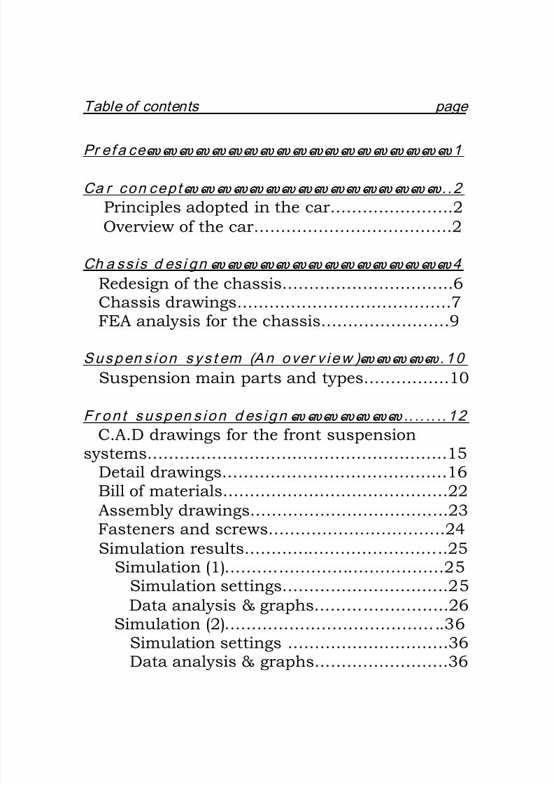
Table of contents page
Pr ef a ce…………………………………………………1
Ca r con cept…………………………………………..2
Principles adopted in the car…………………..2
Overview of the car……………………………….2
Ch a ss is d es i gn ………………………………………4
Redesign of the chassis…………………………..6Chassis drawings………………………………….7FEA analysis for the chassis……………………9
Suspen s ion sys t em (An over v iew )…………….10
Suspension main parts and types…………….10
Fr on t suspen s ion d es ign ………………….. .. .. .. 12C.A.D drawings for the front suspension
systems……………………….……………………….15Detail drawings……………………………………16Bill of materials……………………………………22
Assembly drawings……………………………….23Fasteners and screws……………………………24
Simulation results………………………………..25Simulation (1)………..…………………………25
Simulation settings………………………….25
Data analysis & graphs…………………….26Simulation (2)…………………………………..36
Simulation settings …………………………36Data analysis & graphs…………………….36

8/12/2019 u-j-buggy
http://slidepdf.com/reader/full/u-j-buggy 3/74
St r ess ana l y s i s f o r t h e f r on t a x el ……………4 1
Detailed results……………………………………42
St eer i n g sys t em (An over v i ew )…………………44
Turning a car………………………………………44Steering system main parts and types………44
Rack and pinion steering…………………….45Recirculating-ball steering…………………..46
Steer i n g sys t em d es ign …………………………4 8Simulation settings (initial settings)…………49Simulation results (data analysis)……………49
C.A.D drawings for the rack and pinionsteering system……………………………………...53
Detail drawings…………………………………54
Bill of materials…………………………………61
Assembly drawings…………………………….62Fasteners and screws…………………………68
A fu t u r e l ook ……………………………………….6 9
Conc l u s i o n s a n d l ea r n ed l es sons……………6 9
Refer en ces…………………………………………..7 1

8/12/2019 u-j-buggy
http://slidepdf.com/reader/full/u-j-buggy 4/74
Design, simulation, stresses and force analysis for
a chassis, front suspension system, and steeringsystem of an off-road buggy car
Preface.
The most mechanism system used worldwide is the car, sothrough the past years this field had many upgrades and innovations in
the concepts of designing the cars, due to the high competition betweenthe manufacturing companies around the world in a race to win thecustomer satisfaction. The results is a very high technologic cars that
covers every aspect in the designing of cars including car performance,
safety, luxury, economical aspects, liability and reliability.
Until this moment the Arabic world with all the human and
natural resources it has didn’t have a footstep in the field ofmanufacturing and producing cars, with taking in consideration the
necessity of cars for the Arabic citizen nowadays and the economical
load above these countries for importing the cars, and on the other
hand, the high economical benefits from having a local manufacturedcar, and the saving of the country incomes from being transferred to the
foreign countries, which will be reflected on the living level of the
country’s citizens, for all what is mentioned above, I think that theArabic countries should have a second thought about the idea of making
a local manufactured car.
So for me as a graduated mechanical engineer, and because of my
believe that the science only useful when someone could make from it auseful output to life, I choused my graduation project to be a startingpoint in the way of designing a local car, which is suitable for the
country we live in, and could be manufactured using local resources andmanufacturing capabilities, so to obtain an economical price car
suitable for the average income person.

8/12/2019 u-j-buggy
http://slidepdf.com/reader/full/u-j-buggy 5/74
Car concept.
The basic concept for the car is to be an off -road one-seated car ,with a rear engine. The car should be suitable for roaming in theJordanian deserts as in (Wadi rum desert).
Principles adopted in the car.
Some of the principles that I would adopt in this car are: -1- To be low in weight as possible.
2- A small car in dimensions.
3- To use in it local produced mechanical parts as possible.4- To have an energetic look of an off-road sport car.5- Low price car.
6- To consist of easy changeable mechanical parts when they are
damaged.
7- An acceptable level of safety.
Overview of the car.
The car would have a chassis consist from hollow roll bars, andhollow rectangular sections beams. This will insure a low weight
chassis, a low price chassis, which could be made in the universityworkstations, by just welding the beams to the prescribed dimensions ofthe chassis. The chassis design and the dimensions of the hollow cross-
sections that would be used in it depended on a one-dimensional finiteelement analysis (FEA) for the chassis using [COSMOSM software].
The body of the car will be the same chassis.
The car will have a motorcycle engine, which will be installedbehind the driver seat, at the rear end of the car, in the place that is
shown in figure (1).
8/12/2019 u-j-buggy
http://slidepdf.com/reader/full/u-j-buggy 6/74
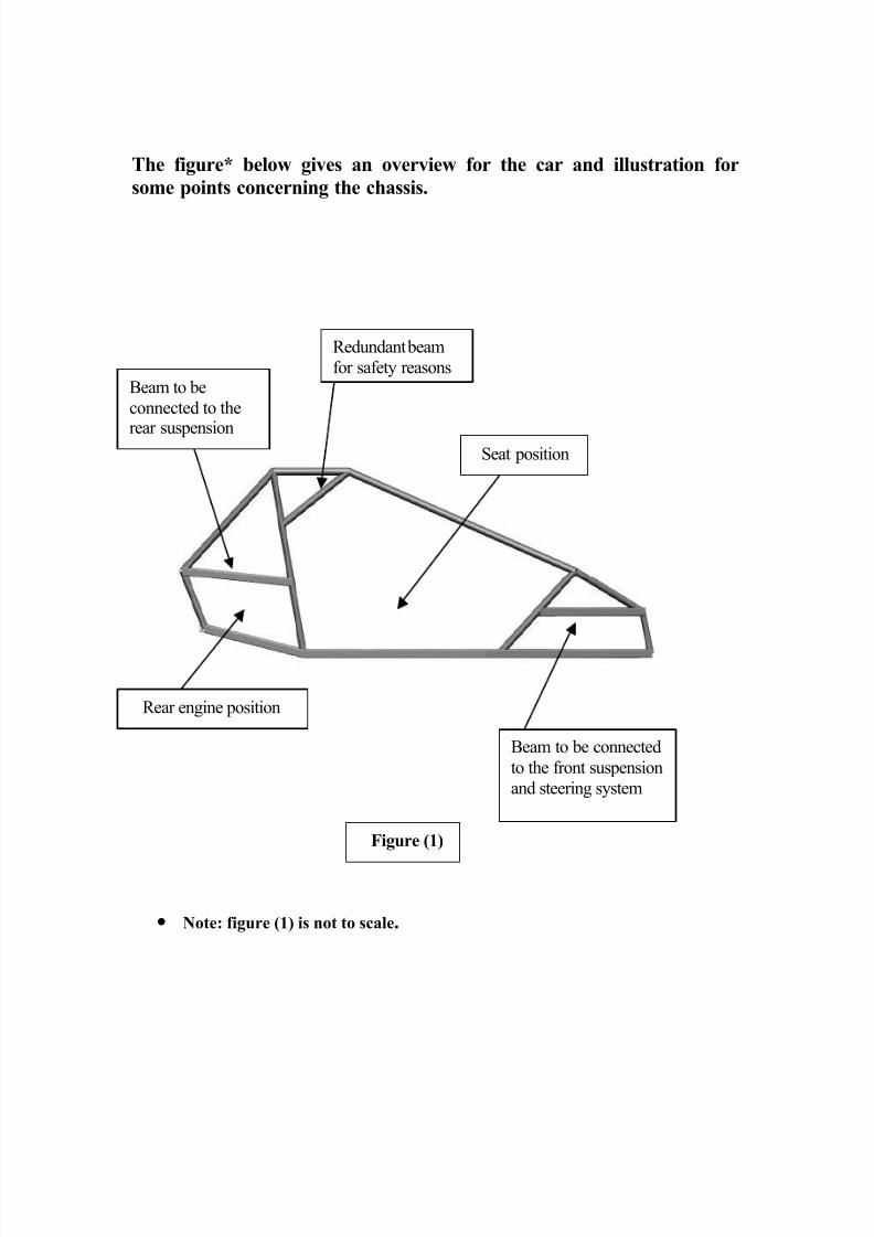
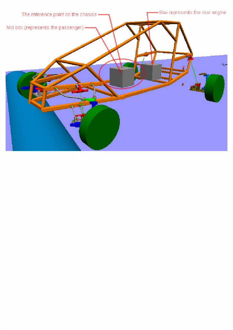
The figure* below gives an overview for the car and illustration for
some points concerning the chassis.
Rear engine position
Seat position
Beam to be
connected to the
rear suspension
Beam to be connected
to the front suspension
and steering system
Redundant beam
for safety reasons
Figure (1)
• Note: figure (1) is not to scale.

8/12/2019 u-j-buggy
http://slidepdf.com/reader/full/u-j-buggy 7/74
Chassis design.
After studying some of the chassis shapes of some off-road buggycars from there pictures which I downloaded from the Internet, and
after I could measure the dimensions of a buggy car chassis that I found
in (Wadi Al-saiyr industrial city), I started drawing sketches for the
chassis depending on the principles I mentioned it before.
Then I used mechanical desktop software, which helps me a lot invisualizing my imagination about the chassis in a 3D solid modeling.
The first modeling of the chassis is shown in figure (2). As it could
be seen clearly the curves of the beams is very hard to be manufacturedhere, as there is not any bending machine that can do such job in the
university workstations. The chassis in this model consist totally ofhollow roll bars section beams, which is not the best suitable beams to
be used incase of bending stresses as the case of lower frame of the
chassis, and also the cross section diameter of (10 cm) outer diameterand (8.85 cm) inner diameter in this model is thicker than what should
be for a low weight car, the (FEA) results which is included next, prove
also that the cross-section should be narrower.
High bending stresses
for lower frame beams
Hard to be obtainedcurves using local
manufacturing capabilities
Thick pipe
diameter
Figure (2)

8/12/2019 u-j-buggy
http://slidepdf.com/reader/full/u-j-buggy 8/74

8/12/2019 u-j-buggy
http://slidepdf.com/reader/full/u-j-buggy 9/74
Redesign of the chassis.
In the new chassis design, the roll bars of the lower frame and thebars which is connected to the front and rear suspensions changed into
hollow rectangular cross-section beams. As seen in the figure all the
curves have been removed from the beams in the chassis, so the chassis
now consist just of straight beams, which don’t any machiningoperations else to be cut to size using available steel saw then welded
together using a DC-welding machine. The mass of this chassisaccording to Cosmosm and mechanical desktop software is
approximately (100 kg) with the cross-section dimensions given in the
next figures
Rectangular
hollow section to
stand bending
stresses
Straight beams
welded together.
Figure (3)

8/12/2019 u-j-buggy
http://slidepdf.com/reader/full/u-j-buggy 10/74

8/12/2019 u-j-buggy
http://slidepdf.com/reader/full/u-j-buggy 11/74

8/12/2019 u-j-buggy
http://slidepdf.com/reader/full/u-j-buggy 12/74
VWUHVVHV[ [ EEPS

8/12/2019 u-j-buggy
http://slidepdf.com/reader/full/u-j-buggy 13/74
Suspension system (An overview).
"Suspension," when discussing cars, refers to the use of front andrear springs to suspend a vehicle's "sprung" weight. The springs usedon today's cars and trucks are constructed in a variety of types, shapes,
sizes, rates, and capacities. Types include leaf springs, coil springs, airsprings, and torsion bars. These are used in sets of four for each vehicle,
or they may be paired off in various combinations and are attached by
several different mounting techniques. The suspension system also
includes shocks and/or struts, and sway bars.
Back in the earliest days of automobile development, when most of
the car's weight (including the engine) was on the rear axle, steering wasa simple matter of turning a tiller that pivoted the entire front axle.When the engine was moved to the front of the car, complex steering
systems had to evolve. The modern automobile has come a long way
since the days when "being self-propelled" was enough to satisfy the carowner. Improvements in suspension and steering, increased strength
and durability of components, and advances in tire design and
construction have made large contributions to riding comfort and to
safe driving.
The suspension system has two basic functions, to keep the car'swheels in firm contact with the road and to provide a comfortable ride
for the passengers. A lot of the system's work is done by the springs.
Under normal conditions, the springs support the body of the car evenly
by compressing and rebounding with every up-and-down movement.This up-and-down movement, however, causes bouncing and swaying
after each bump and is very uncomfortable to the passenger. Theseundesirable effects are reduced by the shock absorbers.
Suspension main parts and types.
The main part of the suspension is the spring. The three types of
springs used are the coil spring, leaf spring and torsion bar.
Coil springs and torsion bars are generally used in the front whereasleaf springs are generally used in the rear. Coil springs are generally
8/12/2019 u-j-buggy
http://slidepdf.com/reader/full/u-j-buggy 14/74
installed between the upper and lower control arms with the shock
absorber mounted inside the spring. In some cases, the coil spring is
mounted on top of the upper control arm and a spring tower formed inthe front-end sheet metal. Coil springs come in many "rates" and can
be used to change the handling and ride characteristics of a vehicle.
Leaf springs are made from layers of spring steel bolted together
through the center of the leafs. This center bolt locates the spring to the
axle housing and is attached to the housing with large U-bolts. The endsof the leaf spring are attached to the frame or body through a shackle
that allows the spring to flex without tearing out. The leaf spring alsoacts as control arms to keep the axle housing in proper position.
Most trucks with a solid beam front end still use leaf springs on the
front. Some cars use a single leaf spring, front and rear, transverselymounted. In other words, the springs are mounted 90 degrees to the
center of the car.
Another important part is the hydraulic shock absorber. Something
that has not changed too much since its use started sometime in the1930's.
The operating principle of standard hydraulic shock absorbers is in
forcing fluid through restricting openings in the valves. This restrictedflow serves to slow down and control rapid movement in the car springs
as they react to road irregularities. Usually, spring-loaded valves
control fluid flow through the pistons. Hydraulic shock absorber
automatically adapt to the severity of the shock. If the axle movesslowly, resistance to the flow of fluid will be light. If the axle movement
is rapid or violent, the resistance is stronger, since more time is required
to force fluid through the openings.
By these actions and reactions, the shock absorbers permit a softride over small bumps and provide firm control over spring action for
cushioning large bumps. The double-acting units must be effective in
both directions because spring rebound can be almost as violent as the
original action that compressed the shock absorber.
Some vehicles came with a control that allowed the driver to selectthe ride type. By setting a control in the passenger compartment, a

8/12/2019 u-j-buggy
http://slidepdf.com/reader/full/u-j-buggy 15/74
motor on the top of the shock would rotate a set of different sized valves
inside the shock to change the damping ability of the shock. There are
usually three settings, Firm, Normal and Soft.
In an active suspension system there is a small sonar unit mountedin the bottom of the front bumper. The sonar unit sends a signal down
onto the road and takes a "picture" of the road surface. This "picture"
is sent to a control unit to automatically change the valving inside the
shock to compensate for the road surface and maintain a smooth ride.
Another component of the suspension system is the sway bar. Somecars require stabilizers to steady the chassis against front-end roll and
sway on turns. Stabilizers are designed to control this centrifugaltendency that forces a rising action on the side toward the inside of the
turn. When the car turns and begins to lean over, the sway bar uses theupward force on the outer wheel to lift on the inner wheel, thus keeping
the car more level.
Finally, we have the control arms. The primary job of the control
arms is to mount the suspension to the frame or body of the vehicle andto allow the suspension to move and keep it in it's proper place. They
come in all shapes and sizes and are specifically designed to maintainthe geometry of the suspension in a wide range of movement. The most
common problem is that the bushings at the body mounting points wearout causing unwanted movement at worst and a terrible squeaking noise
at best. Next, the design of the front suspension of the buggy car will be
put in plain words.
Front suspension design.
As an off-road car, the main features of the suspension should be toabsorb high-shock forces due to the rough road, and have a high degree
of freedom in the vertical direction of the ground; i.e to have highamplitude, so depending on these conditions I could come up with a
front suspension design. One of the main challenges in designing the
suspension is how and on which point should the suspension be
connected to the car chassis, in a way that assure a free moving for thesuspension in the (Z-direction) – the vertical direction to the ground –
8/12/2019 u-j-buggy
http://slidepdf.com/reader/full/u-j-buggy 16/74
while at the same time prevent the moving of the suspension in the (X
and Y directions) of course relative to the body, with taking in
consideration that these connection should be designing in a way thatderive minimum forces on them due to the axial and bending forces
which is transformed from the wheel to the axel to the connections, sothe connections should be capable of standing these forces. For these
reasons I used (working model) software, which help me a lot in
simulating the movement of the car over a road-pump and the reaction
of the suspension due to the pump, as the accompanied movie (avi file)shows, the results will be discussed later on this report.
The basic principle of the first design of the suspension is an
integration of TWO [four-bar-linkage mechanisms], as shown in figure(4). The final dimensions of the bar connections still under study
depending on the angle which should be set to the wheel, as theseconnection will play the main factor in determining the angles of the
wheel.
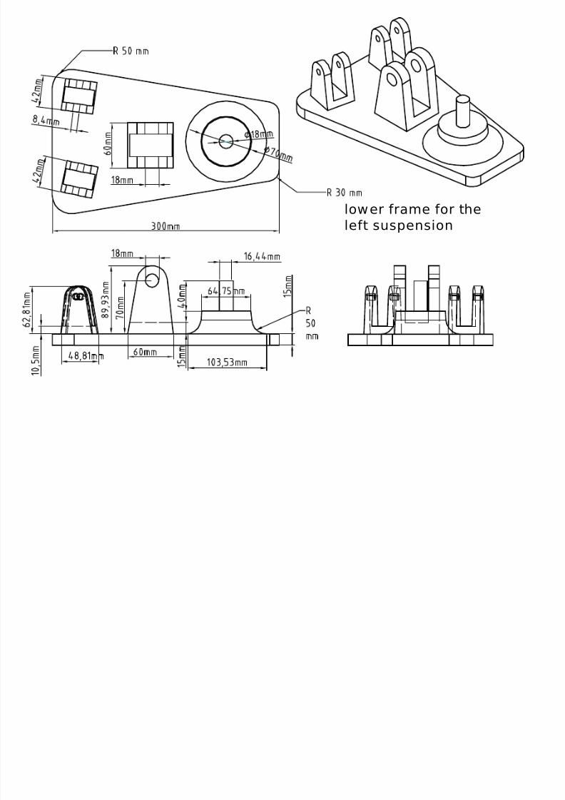
The spring-damper mechanism is connected to a two brackets,
one is fixed by welding to the chassis and the other is fixed also bywelding to the lower frame of the suspension mechanism. The spring-
damper is free to revolute parallel to its plane of movement, but limitedto the bars connections length. By this type of connection the shear or
bending force applied to the spring-damper would be minimum, whichis a desired result, and the force applied will be in an axial form in the
same direction of the spring-damper movement.
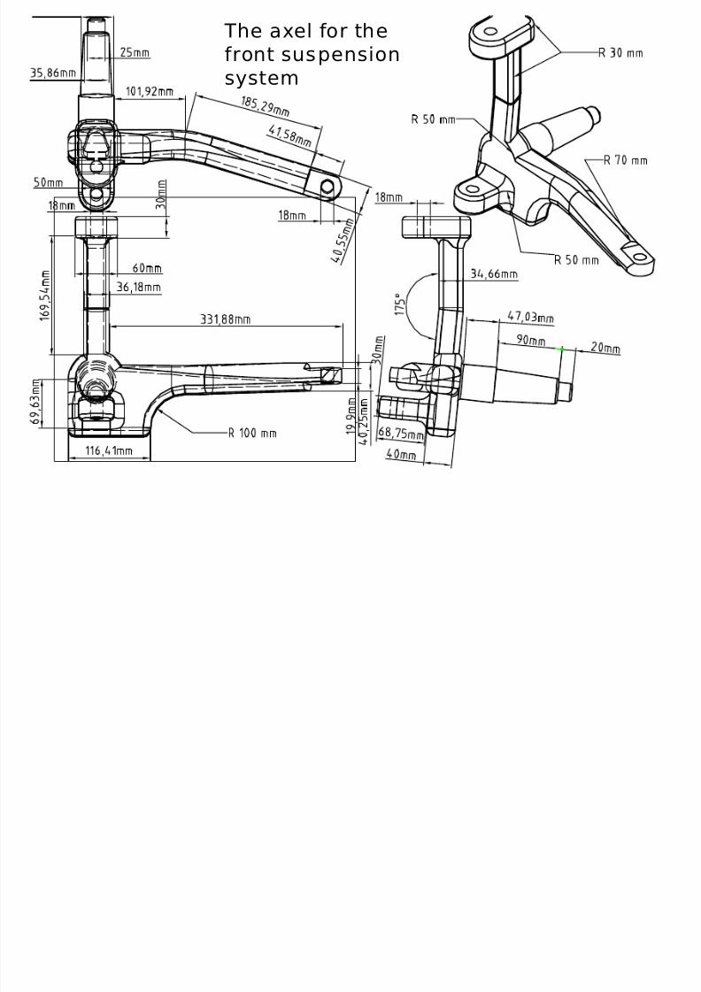
The axel is designed in a way that makes it possible for the wheelto revolute around a fixed axes relative to the suspension, this constraint
permits a rotational (D.O.F) for the axel in a plane parallel to the lower
frame plane (X-Y plane), the rotational movement is limited just to the
constraints of the steering system which will be discussed later. Theseparator between the axel body and both the lower and upper framebodies will be two axial roller bearings, which will permit the rotation of
the axel with the least amount of friction force.
The type of connection between the bars and the lower and upperframe would be a plane bearings, which is fixed by screw and nuts, but
the specific types of nuts and bearing will be determined when the frontsuspension reach it’s final design.
8/12/2019 u-j-buggy
http://slidepdf.com/reader/full/u-j-buggy 17/74
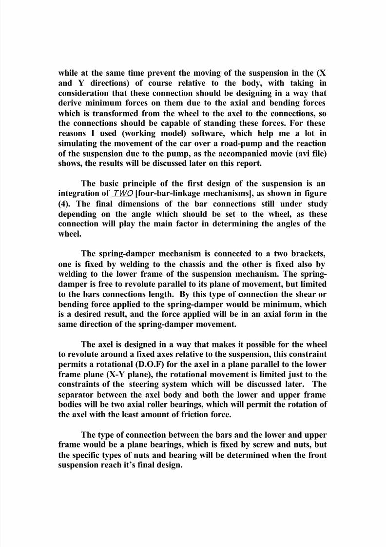
The figure below shows the main parts of the suspension.
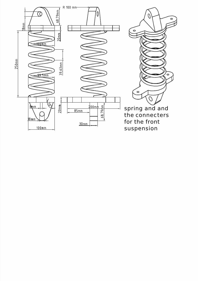
Spring-damper
system
Upper-frame
Axel
Connecter to
the steering
system
Lower frame
Upper bracket
Bars
Plane bearings
Axial bearing
Figure (4)

8/12/2019 u-j-buggy
http://slidepdf.com/reader/full/u-j-buggy 18/74
C.A.D DRAWINGS FOR THE FRONT
SUSPENSION SYSTMEM
DETAILS
&ASSEMBLIES
8/12/2019 u-j-buggy
http://slidepdf.com/reader/full/u-j-buggy 19/74
The axel for the
front suspension
system
8/12/2019 u-j-buggy
http://slidepdf.com/reader/full/u-j-buggy 20/74
lower frame for the
left suspension

8/12/2019 u-j-buggy
http://slidepdf.com/reader/full/u-j-buggy 21/74
Wheel disk

8/12/2019 u-j-buggy
http://slidepdf.com/reader/full/u-j-buggy 22/74
spring connecter
8/12/2019 u-j-buggy
http://slidepdf.com/reader/full/u-j-buggy 23/74
spring and and
the connecters
for the front
suspension

8/12/2019 u-j-buggy
http://slidepdf.com/reader/full/u-j-buggy 24/74
Upper frame for the
front suspension
8/12/2019 u-j-buggy
http://slidepdf.com/reader/full/u-j-buggy 25/74
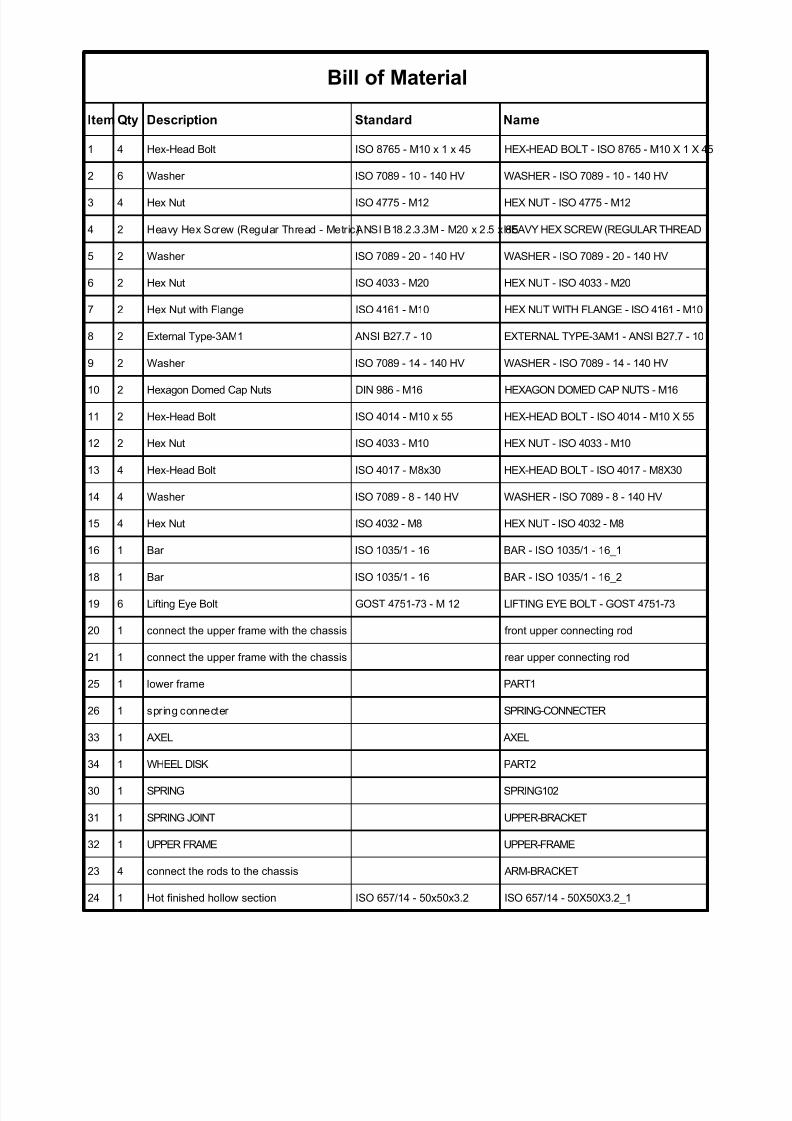
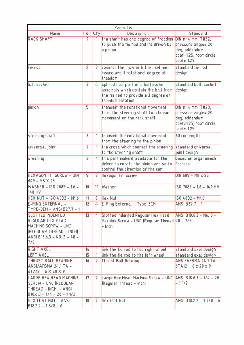
Bill of Material
Item Qty Description Standard Name
1 4 Hex-Head Bolt ISO 8765 - M10 x 1 x 45 HEX-HEAD BOLT - ISO 8765 - M10 X 1 X 45
2 6 Washer ISO 7089 - 10 - 140 HV WASHER - ISO 7089 - 10 - 140 HV
3 4 Hex Nut ISO 4775 - M12 HEX NUT - ISO 4775 - M12
4 2 Heavy Hex Screw (Regular Thread - Metric)ANSI B18.2.3.3M - M20 x 2.5 x 85HEAVY HEX SCREW (REGULAR THREAD
5 2 Washer ISO 7089 - 20 - 140 HV WASHER - ISO 7089 - 20 - 140 HV
6 2 Hex Nut ISO 4033 - M20 HEX NUT - ISO 4033 - M20
7 2 Hex Nut with Flange ISO 4161 - M10 HEX NUT WITH FLANGE - ISO 4161 - M10
8 2 External Type-3AM1 ANSI B27.7 - 10 EXTERNAL TYPE-3AM1 - ANSI B27.7 - 10
9 2 Washer ISO 7089 - 14 - 140 HV WASHER - ISO 7089 - 14 - 140 HV
10 2 Hexagon Domed Cap Nuts DIN 986 - M16 HEXAGON DOMED CAP NUTS - M16
11 2 Hex-Head Bolt ISO 4014 - M10 x 55 HEX-HEAD BOLT - ISO 4014 - M10 X 55
12 2 Hex Nut ISO 4033 - M10 HEX NUT - ISO 4033 - M10
13 4 Hex-Head Bolt ISO 4017 - M8x30 HEX-HEAD BOLT - ISO 4017 - M8X30
14 4 Washer ISO 7089 - 8 - 140 HV WASHER - ISO 7089 - 8 - 140 HV
15 4 Hex Nut ISO 4032 - M8 HEX NUT - ISO 4032 - M8
16 1 Bar ISO 1035/1 - 16 BAR - ISO 1035/1 - 16_1
18 1 Bar ISO 1035/1 - 16 BAR - ISO 1035/1 - 16_2
19 6 Lifting Eye Bolt GOST 4751-73 - M 12 LIFTING EYE BOLT - GOST 4751-73
20 1 connect the upper frame with the chassis front upper connecting rod
21 1 connect the upper frame with the chassis rear upper connecting rod
25 1 lower frame PART1
26 1 spring connecter SPRING-CONNECTER
33 1 AXEL AXEL
34 1 WHEEL DISK PART2
30 1 SPRING SPRING102
31 1 SPRING JOINT UPPER-BRACKET
32 1 UPPER FRAME UPPER-FRAME
23 4 connect the rods to the chassis ARM-BRACKET
24 1 Hot finished hollow section ISO 657/14 - 50x50x3.2 ISO 657/14 - 50X50X3.2_1

8/12/2019 u-j-buggy
http://slidepdf.com/reader/full/u-j-buggy 26/74
FASTENERS AND
SCREWS FOR THE
FRONT SUSPENSION
SYSTEM

8/12/2019 u-j-buggy
http://slidepdf.com/reader/full/u-j-buggy 27/74
Assembly for the front
suspension system &
presentation for the
methods of connection
8/12/2019 u-j-buggy
http://slidepdf.com/reader/full/u-j-buggy 28/74
Simulation results
Simulation ( 1 )
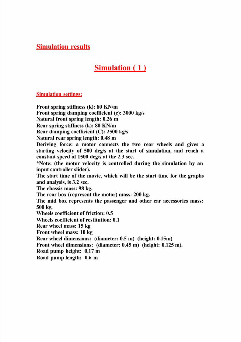
Simulation settings:
Front spring stiffness (k): 80 KN/mFront spring damping coefficient (c): 3000 kg/s
Natural front spring length: 0.26 mRear spring stiffness (k): 80 KN/mRear damping coefficient (C): 2500 kg/s
Natural rear spring length: 0.48 m
Deriving force: a motor connects the two rear wheels and gives a
starting velocity of 500 deg/s at the start of simulation, and reach aconstant speed of 1500 deg/s at the 2.3 sec.
*Note: (the motor velocity is controlled during the simulation by aninput controller slider).
The start time of the movie, which will be the start time for the graphs
and analysis, is 3.2 sec.
The chassis mass: 98 kg.The rear box (represent the motor) mass: 200 kg.
The mid box represents the passenger and other car accessories mass:
500 kg.Wheels coefficient of friction: 0.5
Wheels coefficient of restitution: 0.1Rear wheel mass: 15 kg
Front wheel mass: 10 kg
Rear wheel dimensions: (diameter: 0.5 m) (height: 0.15m)Front wheel dimensions: (diameter: 0.45 m) (height: 0.125 m).Road pump height: 0.17 m
Road pump length: 0.6 m

8/12/2019 u-j-buggy
http://slidepdf.com/reader/full/u-j-buggy 29/74
Data analysis:
The following graph shows the change in the chassis position in the
direction perpendicular to the road as it moves across the road pump.The reference point, which the altitude is measured on it, is a point on
the upper surface of the mid box, which is rigid relative to the chassis.
chassis position in the Z direction (mm)vs. t (s)
220
230
240
250
260
270
280
290
300
310
320
330
340
350
360
370
380
3.2 3.4 3.6 3.8 4 4.2 4.4 4.6 4.8 5 5.2 5.4 5.6 5.8 6 6.2 6.4
8/12/2019 u-j-buggy
http://slidepdf.com/reader/full/u-j-buggy 30/74

8/12/2019 u-j-buggy
http://slidepdf.com/reader/full/u-j-buggy 31/74
angular veloci ty of the left rear wheel (de g/s) vs. t (s)
30 0
40 0
50 0
60 0
70 0
80 0
90 0
1000
1100
1200
1300
1400
1500
1600
1700
1800
1900
2000
2100
2200
0 1 2 3 4 5 6
As it could be seen from the above graph that angular velocity is almost
constant from the time 3.2 sec to the time 5 sec which is the time of the
movie and the analysis.co n t a c t f o r ce b e t w e e n t h e g ro u n d a n d t h e f r o n t l e f t w h e e l (N ) vs . t (s )
0
2 0 0
4 0 0
6 0 0
8 0 0
1 0 0 0
1 2 0 0
1 4 0 0
1 6 0 0
1 8 0 02 0 0 0
2 2 0 0
2 4 0 0
2 6 0 0
2 8 0 0
3 0 0 0
3 2 0 0
3 4 0 0
3 6 0 0
3 8 0 0
4 0 0 0
4 2 0 0
4 4 0 0
4 6 0 0
4 8 0 0
5 0 0 0
3 . 2 3 .4 3.6 3 . 8 4 4.2 4.4 4.6 4 . 8 5 5.2 5 . 4 5 .6 5 . 8 6 6.2 6 . 4
Note: the zero contact force from (3.4-3.9) sec, because the meter didn’t measure the contactforce between the pump and the wheel as the pump didn’t consider a part from the ground
8/12/2019 u-j-buggy
http://slidepdf.com/reader/full/u-j-buggy 32/74
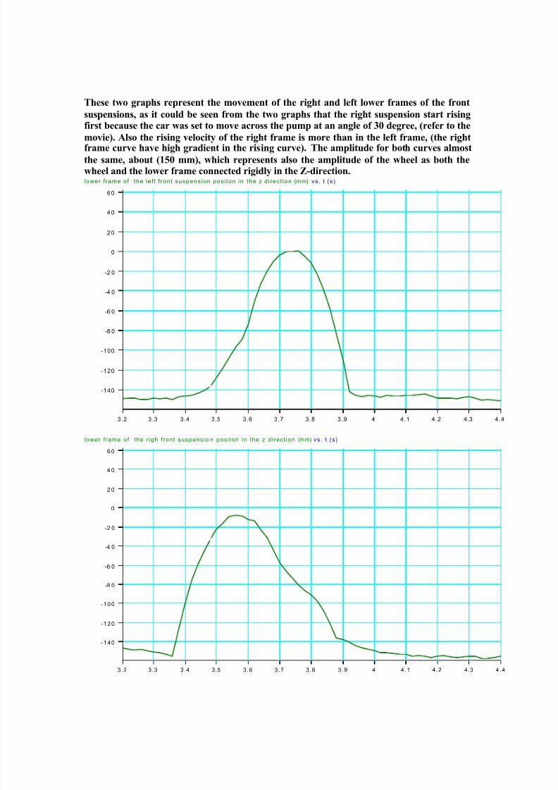
These two graphs represent the movement of the right and left lower frames of the front
suspensions, as it could be seen from the two graphs that the right suspension start risingfirst because the car was set to move across the pump at an angle of 30 degree, (refer to the
movie). Also the rising velocity of the right frame is more than in the left frame, (the rightframe curve have high gradient in the rising curve). The amplitude for both curves almost
the same, about (150 mm), which represents also the amplitude of the wheel as both thewheel and the lower frame connected rigidly in the Z-direction.lower f rame of the le f t f ront suspension posi ton in the z d i rect ion (mm) vs. t (s)
-140
-120
-100
-8 0
-6 0
-4 0
-2 0
0
2 0
4 0
6 0
3.2 3.3 3.4 3.5 3.6 3.7 3.8 3.9 4 4.1 4.2 4.3 4.4
lower f rame of the r igh f ront suspensio n posi ton in the z d irect ion (mm) vs. t (s)
- 140
-120
-100
-8 0
-6 0
-4 0
-2 0
0
2 0
4 0
6 0
3.2 3.3 3.4 3.5 3.6 3.7 3.8 3.9 4 4.1 4.2 4.3 4.4

8/12/2019 u-j-buggy
http://slidepdf.com/reader/full/u-j-buggy 33/74
This graph shows the velocity of the car, which is almost constant
around (2600 mm/s) or (9.4 km/h)velocity of the chassis in the X-direction ( parallel to the road path) (mm/s) vs. t (s)
0
20 0
40 0
60 0
80 0
1000
1200
1400
1600
1800
2000
2200
2400
2600
2800
3000
3200
3400
3600
3800
4000
3.2 3.4 3.6 3.8 4 4.2 4.4 4.6 4.8 5 5.2 5.4 5.6 5.8 6 6.2 6.4
velocity of the c hassis in the Y-direction (mm/s) vs. t (s)
0
100
200
300
400
500
600
700
800
900
1000
1100
3.2 3.4 3.6 3.8 4 4.2 4.4 4.6 4.8 5 5.2 5.4 5.6 5.8 6 6.2 6.4

8/12/2019 u-j-buggy
http://slidepdf.com/reader/full/u-j-buggy 34/74
chassis position inthe X-direction chassis position in the y-direction (mm) vs. t (s)
0
1000
2000
3000
4000
5000
6000
7000
8000
9000
10000
11000
12000
13000
0 1 2 3 4 5 6
8/12/2019 u-j-buggy
http://slidepdf.com/reader/full/u-j-buggy 35/74
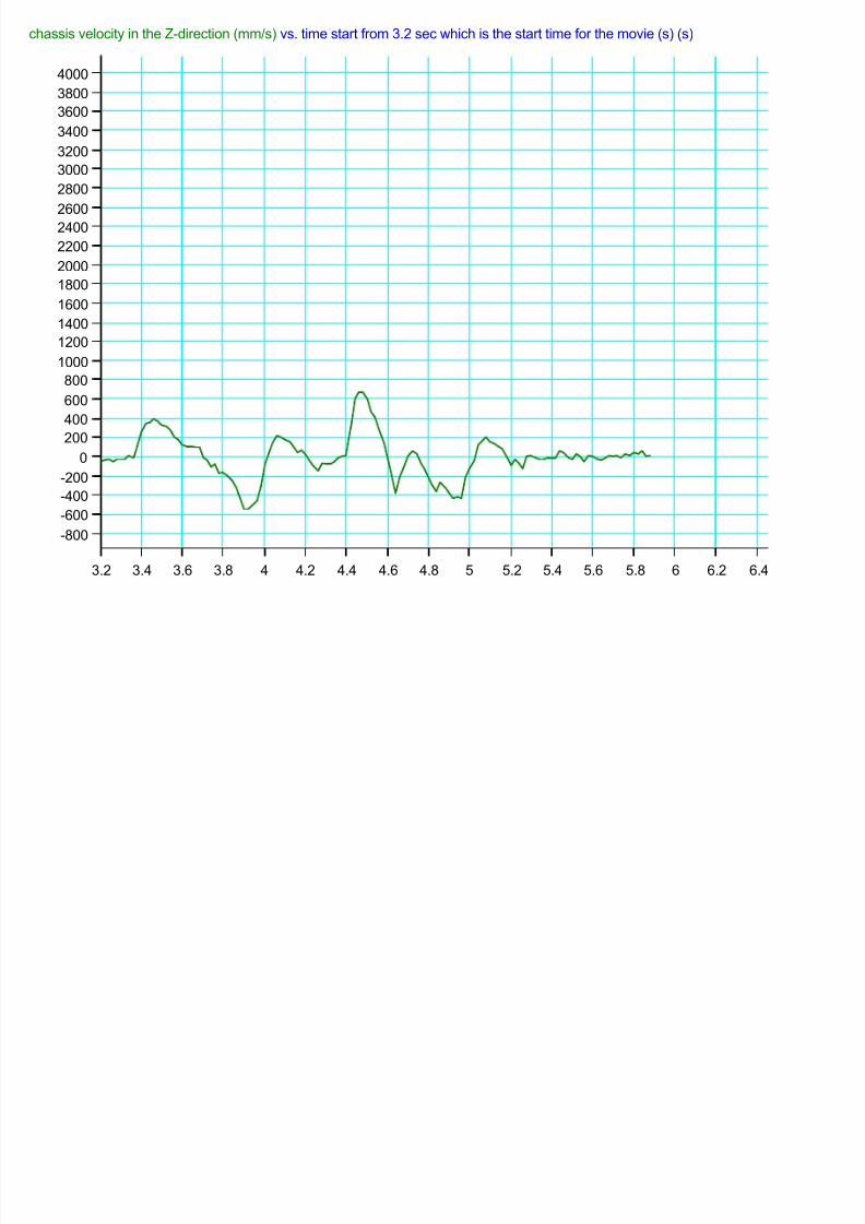
chassis velocity in the Z-direction (mm/s) vs. time start from 3.2 sec which is the start time for the movie (s) (s)
-800
-600
-400
-200
0
200
400
600
800
1000
1200
1400
1600
1800
2000
2200
24002600
2800
3000
3200
3400
3600
3800
4000
3.2 3.4 3.6 3.8 4 4.2 4.4 4.6 4.8 5 5.2 5.4 5.6 5.8 6 6.2 6.4

8/12/2019 u-j-buggy
http://slidepdf.com/reader/full/u-j-buggy 36/74
Magnitude of force acting on the front axel of the left suspension at it's point of connection with the lower frame (N) vs. time (s)
-6000
-5000
-4000
-3000
-2000
-1000
0
1000
2000
3000
4000
5000
6000
7000
3.2 3.4 3.6 3.8 4 4.2 4.4 4.6 4.8 5 5.2 5.4 5.6 5.8 6 6.2 6.4

8/12/2019 u-j-buggy
http://slidepdf.com/reader/full/u-j-buggy 37/74
Impulse magnitude between the left front wheel and the ground (kg mm/s) vs. t (s)
0
10000
20000
30000
40000
50000
60000
70000
80000
90000
3.7 3.8 3.9 4 4.1 4.2 4.3 4.4 4.5

8/12/2019 u-j-buggy
http://slidepdf.com/reader/full/u-j-buggy 38/74
magnitude of force acting on the front lower bar of the front left suspension at it's point of connection with the lower frame (N) vs. time (
-3000
-2000
-1000
0
1000
2000
3000
4000
5000
6000
7000
8000
9000
10000
11000
12000
3.2 3.4 3.6 3.8 4 4.2 4.4 4.6 4.8 5 5.2 5.4 5.6 5.8 6 6.2 6.4

8/12/2019 u-j-buggy
http://slidepdf.com/reader/full/u-j-buggy 39/74
Simulation ( 2 )
Simulation settings:
Front spring stiffness (k): 80 KN/mFront spring damping coefficient (c): 1700 kg/sNatural front spring length: 0.26 m
Rear spring stiffness (k): 60 KN/mRear damping coefficient (C): 500 kg/s
Natural rear spring length: 0.48 m
Deriving force: an applied force to the center of the rear mid beam ofthe chassis, acting in the x-direction, the initial force is 160 N andcontinue to rise until it reach 4000 N.
*Note: (the force magnitude is controlled during the simulation by aninput controller slider).
The chassis mass: 98 kg.
The rear box (represent the motor) mass: 200 kg.
The mid box represents the passenger and other car accessories mass:500 kg.
Wheels coefficient of fri ction: 0.5
Wheels coefficient of restitution: 0.5Rear wheel mass: 15 kg
Front wheel mass: 10 kgRear wheel dimensions: (diameter: 0.5 m) (height: 0.15m)
Front wheel dimensions: (diameter: 0.45 m) (height: 0.125 m).
Road pump height: 0.17 m
Road pump length: 0.6 m
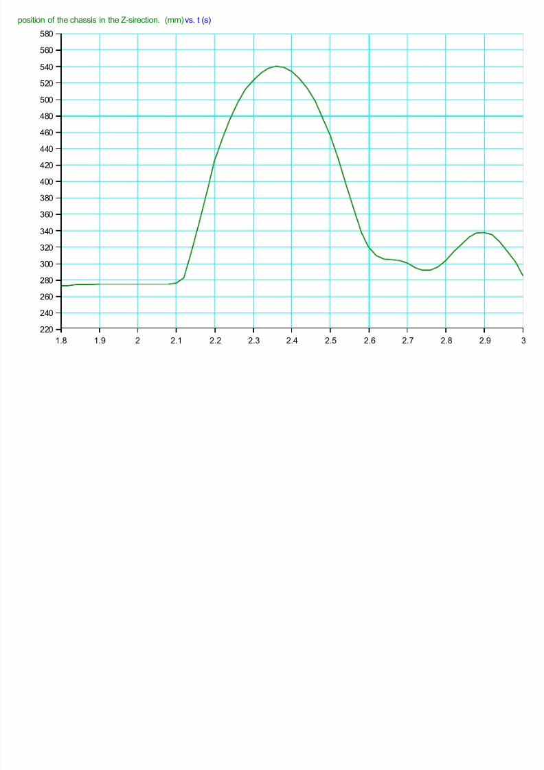
Data analysis:From the movie it could be seen that the car lose control when it hits the
pump. The reason maybe that deriving force acts as a coupling force
with the reaction force from the right wheel, which hit the pump first.
*Note: the average velocity of the car when passing over the pump is(21 km/h), which is relatively high speed for a car over a pump.
8/12/2019 u-j-buggy
http://slidepdf.com/reader/full/u-j-buggy 40/74
position of the chassis in the Z-sirection. (mm) vs. t (s)
220
240
260
280
300
320
340
360
380
400
420
440
460
480
500
520
540
560
580
1.8 1.9 2 2.1 2.2 2.3 2.4 2.5 2.6 2.7 2.8 2.9 3

8/12/2019 u-j-buggy
http://slidepdf.com/reader/full/u-j-buggy 41/74
position of the lower frame of the left suspension in the Z-direction (mm) vs. t (s)
-140
-120
-100
-80
-60
-40
-20
0
20
40
60
80
100
120
140
160
180
200
220
240
260
280
300
1.8 1.9 2 2.1 2.2 2.3 2.4 2.5 2.6 2.7 2.8
8/12/2019 u-j-buggy
http://slidepdf.com/reader/full/u-j-buggy 42/74
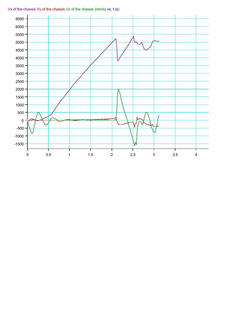
Vx of the chassis Vy of the chassis Vz of the chassis (mm/s) vs. t (s)
-1500
-1000
-500
0
500
1000
1500
2000
2500
3000
3500
4000
4500
5000
5500
6000
6500
0 0.5 1 1.5 2 2.5 3 3.5 4
8/12/2019 u-j-buggy
http://slidepdf.com/reader/full/u-j-buggy 43/74
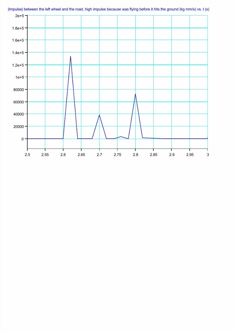
|Impulse| between the left wheel and the road, high impulse because was flying before it hits the ground (kg mm/s) vs. t (s)
0
20000
40000
60000
80000
1e+5
1.2e+5
1.4e+5
1.6e+5
1.8e+5
2e+5
2.5 2.55 2.6 2.65 2.7 2.75 2.8 2.85 2.9 2.95 3
8/12/2019 u-j-buggy
http://slidepdf.com/reader/full/u-j-buggy 44/74
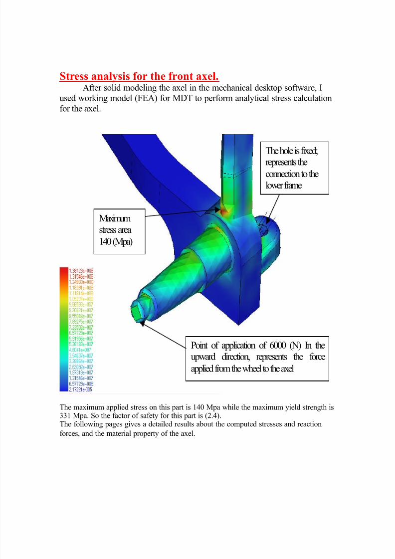
Stress analysis for the front axel.After solid modeling the axel in the mechanical desktop software, I
used working model (FEA) for MDT to perform analytical stress calculationfor the axel.
Maximumstress area
140 (Mpa)
Point of application of 6000 (N) In theupward direction, represents the force
applied from the wheel to the axel
The hole is fixed;represents the
connection to thelower frame
The maximum applied stress on this part is 140 Mpa while the maximum yield strength is331 Mpa. So the factor of safety for this part is (2.4).The following pages gives a detailed results about the computed stresses and reaction
forces, and the material property of the axel.
8/12/2019 u-j-buggy
http://slidepdf.com/reader/full/u-j-buggy 45/74
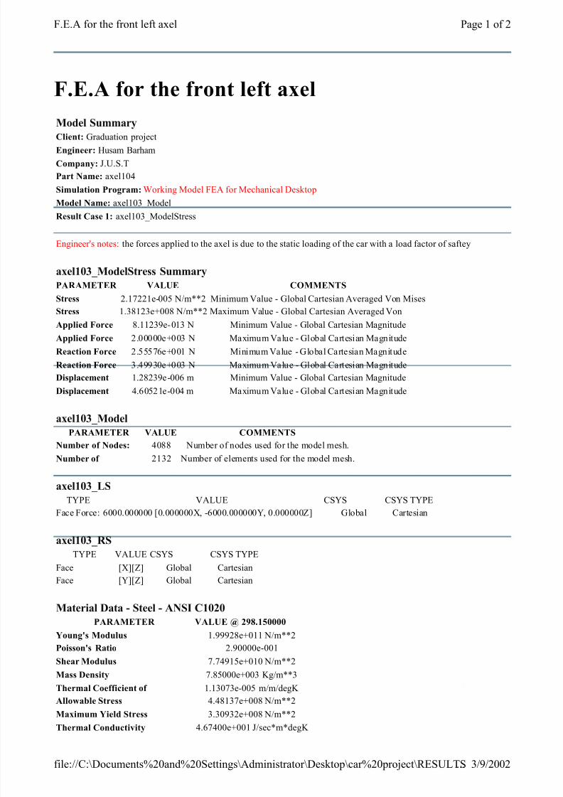
F.E.A for the front left axel
Model Summary
Client: Graduation projectEngineer: Husam Barham
Company: J.U.S.T
Part Name: axel104
Simulation Program: Working Model FEA for Mechanical Desktop
Model Name: axel103_Model
Result Case 1: axel103_ModelStress
Engineer's notes: the forces applied to the axel is due to the static loading of the car with a load factor of saftey
axel103_ModelStress Summary
PARAMETER VALUE COMMENTS
Stress 2.17221e-005 N/m**2 Minimum Value - Global Cartesian Averaged Von Mises
Stress 1.38123e+008 N/m**2 Maximum Value - Global Cartesian Averaged Von
Applied Force 8.11239e-013 N Minimum Value - Global Cartesian Magnitude
Applied Force 2.00000e+003 N Maximum Value - Global Cartesian Magnitude
Reaction Force 2.55576e+001 N Minimum Value - Global Cartesian Magnitude
Reaction Force 3.49930e+003 N Maximum Value - Global Cartesian Magnitude
Displacement 1.28239e-006 m Minimum Value - Global Cartesian Magnitude
Displacement 4.60521e-004 m Maximum Value - Global Cartesian Magnitude
axel103_Model PARAMETER VALUE COMMENTS
Number of Nodes: 4088 Number of nodes used for the model mesh.
Number of 2132 Number of elements used for the model mesh.
axel103_LS
TYPE VALUE CSYS CSYS TYPE
Face Force: 6000.000000 [0.000000X, -6000.000000Y, 0.000000Z] Global Cartesian
axel103_RS
TYPE VALUE CSYS CSYS TYPEFace [X][Z] Global Cartesian
Face [Y][Z] Global Cartesian
Material Data - Steel - ANSI C1020
PARAMETER VALUE @ 298.150000
Young's Modulus 1.99928e+011 N/m**2
Poisson's Ratio 2.90000e-001
Shear Modulus 7.74915e+010 N/m**2
Mass Density 7.85000e+003 Kg/m**3
Thermal Coefficient of 1.13073e-005 m/m/degK
Allowable Stress 4.48137e+008 N/m**2
Maximum Yield Stress 3.30932e+008 N/m**2
Thermal Conductivity 4.67400e+001 J/sec*m*degK
Page 1 of 2F.E.A for the front left axel
3/9/2002file://C:\Documents%20and%20Settings\Administrator\Desktop\car%20project\RESULTS...

8/12/2019 u-j-buggy
http://slidepdf.com/reader/full/u-j-buggy 46/74
Specific Heat 4.18400e+002 J/Kg*degK
axel103_ModelStress - Details (All values are averaged and in the global cartesian coordinatesystem)
PARAMETER X VALUE Y VALUE Z VALUE
Location 9.50000e-003 m 7.10543e-017 m -1.60000e-001 m
Applied Force 0.00000e+000 N -1.32015e-012 N 0.00000e+000 NLocation 4.75000e-003 m -4.75000e-003 m -1.60000e-001 m
Applied Force 0.00000e+000 N -1.00016e+003 N 0.00000e+000 N
Location -2.38761e-009 m -9.50000e-003 m -1.60000e-001 m
Applied Force 0.00000e+000 N -8.11239e-013 N 0.00000e+000 N
Location -4.75000e-003 m -4.74851e-003 m -1.60000e-001 m
Applied Force 0.00000e+000 N -1.00016e+003 N 0.00000e+000 N
Location -9.50000e-003 m 2.98690e-006 m -1.60000e-001 m
Applied Force 0.00000e+000 N -1.69806e-012 N 0.00000e+000 N
Location -4.74701e-003 m 4.75149e-003 m -1.60000e-001 m
Applied Force 0.00000e+000 N -9.99843e+002 N 0.00000e+000 N
Location 5.97141e-006 m 9.50000e-003 m -1.60000e-001 m
Applied Force 0.00000e+000 N -8.76743e-013 N 0.00000e+000 N
Location 4.75299e-003 m 4.75000e-003 m -1.60000e-001 m
Applied Force 0.00000e+000 N -9.99843e+002 N 0.00000e+000 N
Location 2.34778e-010 m 1.49345e-006 m -1.60000e-001 m
Applied Force 0.00000e+000 N -2.00000e+003 N 0.00000e+000 N
axel103_ModelStress Summations PARAMETER X VALUE Y VALUE Z VALUE
Summation of Reaction Forces -1.75476e-003 N 6.00002e+003 N 3.47090e-003 N
Summation of Reaction 1.76022e+003 N*m 6.30627e-002 N*m -1.45127e+000 N*m
Page 2 of 2F.E.A for the front left axel
3/9/2002file://C:\Documents%20and%20Settings\Administrator\Desktop\car%20project\RESULTS...
8/12/2019 u-j-buggy
http://slidepdf.com/reader/full/u-j-buggy 47/74
Steering system (An overview).
You know that when you turn the steering wheel in your car, thewheels turn. Cause and effect, right? However, a lot of interesting stuffgoes on between the steering wheel and the tires to make this happen.
Here are some facts.
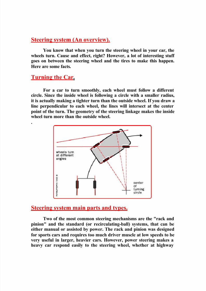
Turning the Car.
For a car to turn smoothly, each wheel must follow a differentcircle. Since the inside wheel is following a circle with a smaller radius,
it is actually making a tighter turn than the outside wheel. If you draw aline perpendicular to each wheel, the lines will intersect at the center
point of the turn. The geometry of the steering linkage makes the insidewheel turn more than the outside wheel.
.
Steering system main parts and types.
Two of the most common steering mechanisms are the "rack and
pinion" and the standard (or recirculating-ball) systems, that can beeither manual or assisted by power. The rack and pinion was designed
for sports cars and requires too much driver muscle at low speeds to bevery useful in larger, heavier cars. However, power steering makes aheavy car respond easily to the steering wheel, whether at highway

8/12/2019 u-j-buggy
http://slidepdf.com/reader/full/u-j-buggy 48/74
speeds or inching into a narrow parking place, and it is normal
equipment for large automobiles. A brief description about each
mechanism is presented next.
Rack-and-pinion Steering.
Rack-and-pinion steering is quickly becoming the most common
type of steering on cars, small trucks and SUVs. It is actually a pretty
simple mechanism.
A rack-and-pinion gear set is enclosed in a metal tube, with eachend of the rack protruding from the tube. A rod, called a tie rod,
connects to each end of the rack.
The pinion gear is attached to the steering shaft. When you turn
the steering wheel, the gear spins, moving the rack. The tie rod at eachend of the rack connects to the steering arm on the spindle (see diagramabove).
The rack-and-pinion gearset does two things:
• It converts the rotational motion of the steering wheel into the
linear motion needed to turn the wheels.
• It provides a gear reduction, making it easier to turn the wheels.

8/12/2019 u-j-buggy
http://slidepdf.com/reader/full/u-j-buggy 49/74
On most cars, it takes three to four complete revolutions of the
steering wheel to make the wheels turn from lock to lock (from far left
to far right).
The steering ratio is the ratio of how far you turn the steering wheel
to how far the wheels turn. For instance, if one complete revolution (360degrees) of the steering wheel results in the wheels of the car turning 20
degrees, then the steering ratio is 360 divided by 20, or 18:1. A higher
ratio means that you have to turn the steering wheel more to get thewheels to turn a given distance. However, less effort is required because
of the higher gear ratio.
Generally, lighter, sportier cars have lower steering ratios thanlarger cars and trucks. The lower ratio gives the steering a quicker
response -- you don't have to turn the steering wheel as much to get thewheels to turn a given distance -- which is a desirable quality in sports
cars. These smaller cars are light enough that even with the lower ratio,the effort required to turn the steering wheel is not excessive. Due to the
light weight of the buggy off-road car and to the rapid reactions in
varying the direction, it has been taken in consideration to have a lower
steering ratio during the design process.
Some cars have variable-ratio steering, which uses a rack-and-pinion gearset that has a different tooth pitch in the center than it has
on the outside. This makes the car respond quickly when starting a turn
(the rack is near the center), and also reduces effort near the wheel's
turning limits.
The advantage of rack & pinion steering is that it is more precisethan the mechanical system. By reducing the number of parts and pivot
points, it can more accurately control wheel direction and is more
responsive. The down side of a rack & pinion steering system is thatthey are prone to leakage requiring replacement of the rack assembly.
Recirculating-ball Steering.
Recirculating-ball steering is used on mainly on trucks. The
linkage that turns the wheels is slightly different than on a rack-and-pinion system.

8/12/2019 u-j-buggy
http://slidepdf.com/reader/full/u-j-buggy 50/74
The recirculating-ball steering gear contains a worm gear. You
can image the gear in two parts. The first part is a block of metal with a
threaded hole in it. This block has gear teeth cut into the outside of it,which engage a gear that moves the pitman arm (see diagram above).
The steering wheel connects to a threaded rod, similar to a bolt, thatsticks into the hole in the block. When the steering wheel turns, it turns
the bolt. Instead of twisting further into the block the way a regular boltwould, this bolt is held fixed so that when it spins, it moves the block,which moves the gear that turns the wheels.

8/12/2019 u-j-buggy
http://slidepdf.com/reader/full/u-j-buggy 51/74
Instead of the bolt directly engaging the threads in the block, all
of the threads are filled with ball bearings that recirculate through the
gear as it turns. The balls actually serve two purposes: First, theyreduce friction and wear in the gear; second, they reduce slop in the
gear. Slop would be felt when you change the direction of the steeringwheel -- without the balls in the steering gear, the teeth would come out
of contact with each other for a moment, making the steering wheel feel
loose.
Power steering in a recirculating-ball system works similarly to a
rack-and-pinion system. Assist is provided by supplying higher-pressurefluid to one side of the block.
Steering system design
After taking in consideration the required performance from anoff-road buggy car, such as the rapid change in directions and the
factors affecting the steering system such as the light weight of the carand the rough road that an off-road car should pass through, I
concluded that a rack and pinion steering mechanism should formulate
the best performance for this car. For these reasons, I made my mind to
design a rack and pinion steering mechanism for the car.
The design process went through two main divisions.
First, are the motion analysis and simulation processes, which are
done with working model software. These simulations help me to
visualize the motion type of the steering mechanism and the functionaryof the system parts. Also, help me in providing the necessary dimensions
for the parts and assembly, which is responsible on giving the bestturning performance as, will be discussed later.
Second, are the C.A.D drawings; details, assemblies and the
means of connections for the steering system parts. In this division a
complete parts dimensions have been presented, which help visualize
the steering system shape.
8/12/2019 u-j-buggy
http://slidepdf.com/reader/full/u-j-buggy 52/74
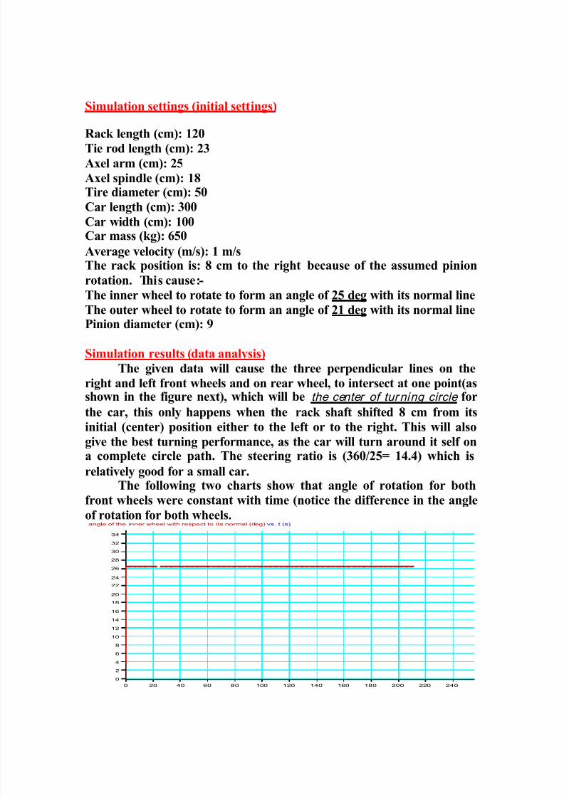
Simulation settings (initial settings)
Rack length (cm): 120Tie rod length (cm): 23
Axel arm (cm): 25
Axel spindle (cm): 18Tire diameter (cm): 50
Car length (cm): 300
Car width (cm): 100Car mass (kg): 650
Average velocity (m/s): 1 m/sThe rack position is: 8 cm to the right because of the assumed pinion
rotation. This cause:-The inner wheel to rotate to form an angle of 25 deg with its normal line
The outer wheel to rotate to form an angle of 21 deg with its normal linePinion diameter (cm): 9
Simulation results (data analysis)
The given data will cause the three perpendicular lines on the
right and left front wheels and on rear wheel, to intersect at one point(asshown in the figure next), which will be the center of turning circle for
the car, this only happens when the rack shaft shifted 8 cm from its
initial (center) position either to the left or to the right. This will also
give the best turning performance, as the car will turn around it self ona complete circle path. The steering ratio is (360/25= 14.4) which is
relatively good for a small car.The following two charts show that angle of rotation for both
front wheels were constant with time (notice the difference in the angle
of rotation for both wheels.angle of the inner wheel with respect to its normal (deg) vs. t (s)
0
2
4
6
8
10
12
14
16
18
20
22
24
26
28
30
32
34
0 20 40 60 80 100 120 140 160 180 200 220 240

8/12/2019 u-j-buggy
http://slidepdf.com/reader/full/u-j-buggy 53/74

8/12/2019 u-j-buggy
http://slidepdf.com/reader/full/u-j-buggy 54/74
angle of the outter wheel with respect to its normal (deg) vs. t (s)
-22
-20
-18
-16
-14
-12
-10
-8
-6
-4
-2
0
0 20 40 60 80 100 120 140 160 180 200 220 240
The next graph shows the position of the car in the x-y direction (considering the carmove in the x-y plane). An important result giving here is that the car rotates around acircle of (8 m) average diameter as the variation between the maximum x-y positions and
the minimum x-y positions relatively show. (Notice that the car rotates about (7 turns) around it self in this simulation as the sinusoidal wave show.
position of the car in the x direction position of the car in the y direction (m) vs. t (s)
-13
-12
-11
-10
-9
-8
-7
-6
-5
-4
-3
-2
-1
0
1
2
3
0 20 40 60 80 100 120 140 160 180 200 220 240

8/12/2019 u-j-buggy
http://slidepdf.com/reader/full/u-j-buggy 55/74
This chart shows the orientation of the car with respect to time. On an
average basis, it took the car 25 second to have a complete 360-degree
turn around its self. The car turns around it self 7 times in thissimulation.
orientation of the car body (deg) vs. time (s)
-260
-240
-220
-200
-180
-160
-140
-120
-100
-80
-60
-40
-200
20
40
60
80
100
120
140
160
180
200
220
240
260
0 20 40 60 80 100 120 140 160 180 200 220 240
The car has an average speed of (1 m/s) as the chart below shows.
average car speed (m/s) vs. t (s)
0
0.1
0.2
0.3
0.4
0.5
0.6
0.7
0.8
0.9
1
1.1
1.2
1.3
1.4
1.5
0 20 40 60 80 100 120 140 160 180 200 220 240
8/12/2019 u-j-buggy
http://slidepdf.com/reader/full/u-j-buggy 56/74
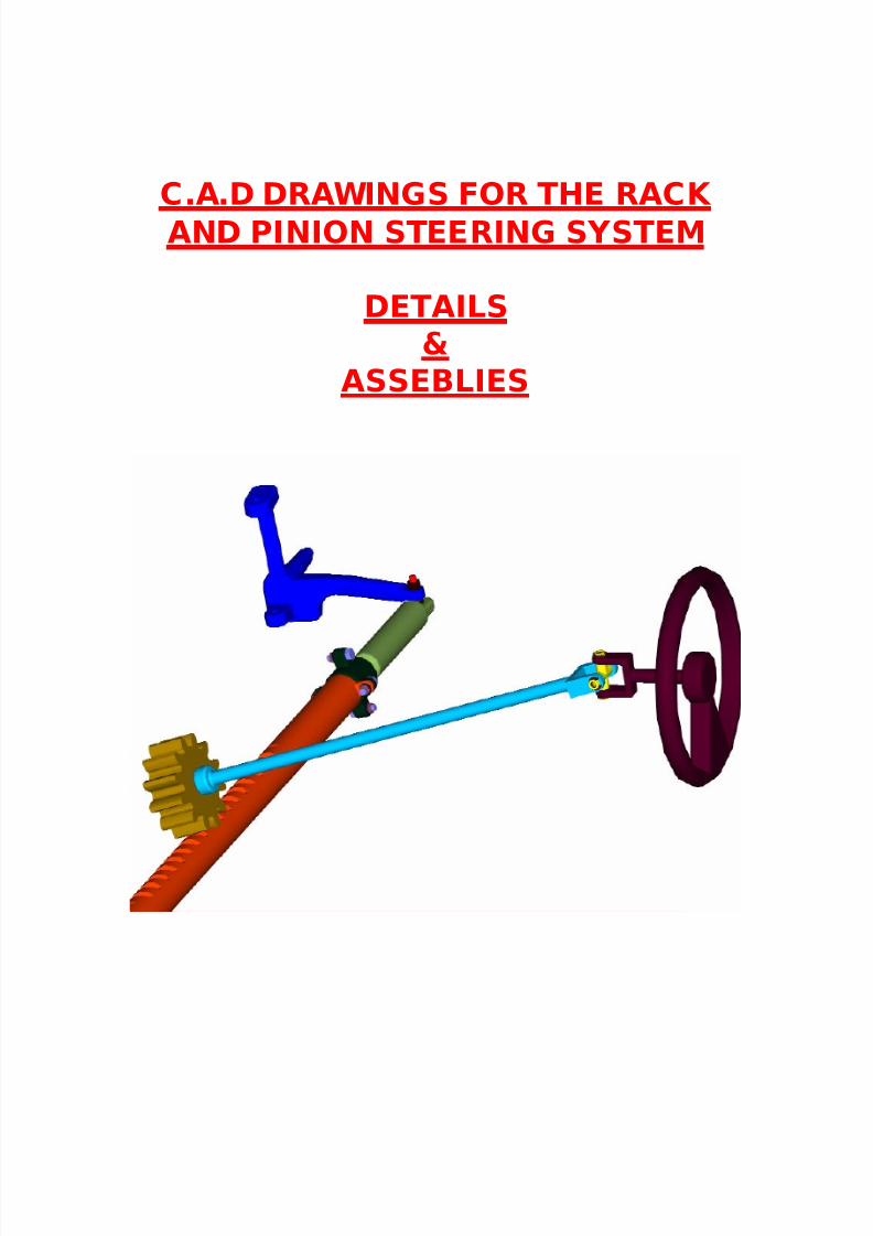
C.A.D DRAWINGS FOR THE RACK
AND PINION STEERING SYSTEM
DETAILS&
ASSEBLIES
8/12/2019 u-j-buggy
http://slidepdf.com/reader/full/u-j-buggy 57/74
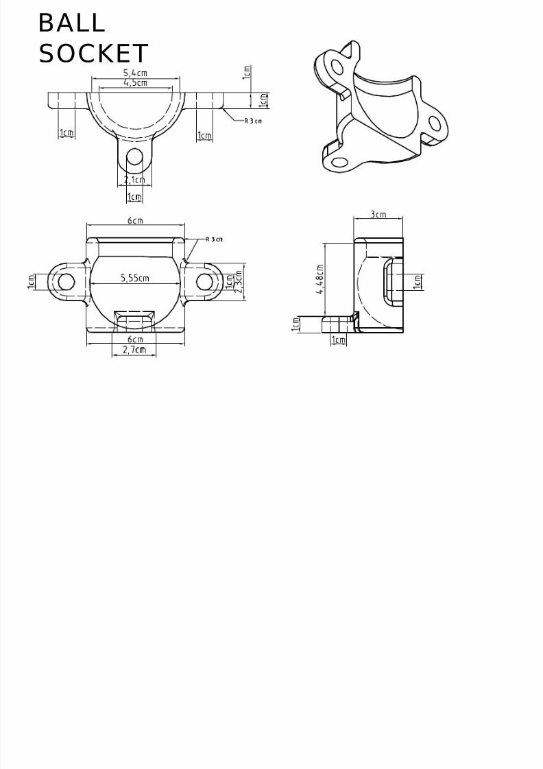
BALL
SOCKET

8/12/2019 u-j-buggy
http://slidepdf.com/reader/full/u-j-buggy 58/74
rack shaft

8/12/2019 u-j-buggy
http://slidepdf.com/reader/full/u-j-buggy 59/74
Tie rod(connecter)
8/12/2019 u-j-buggy
http://slidepdf.com/reader/full/u-j-buggy 60/74
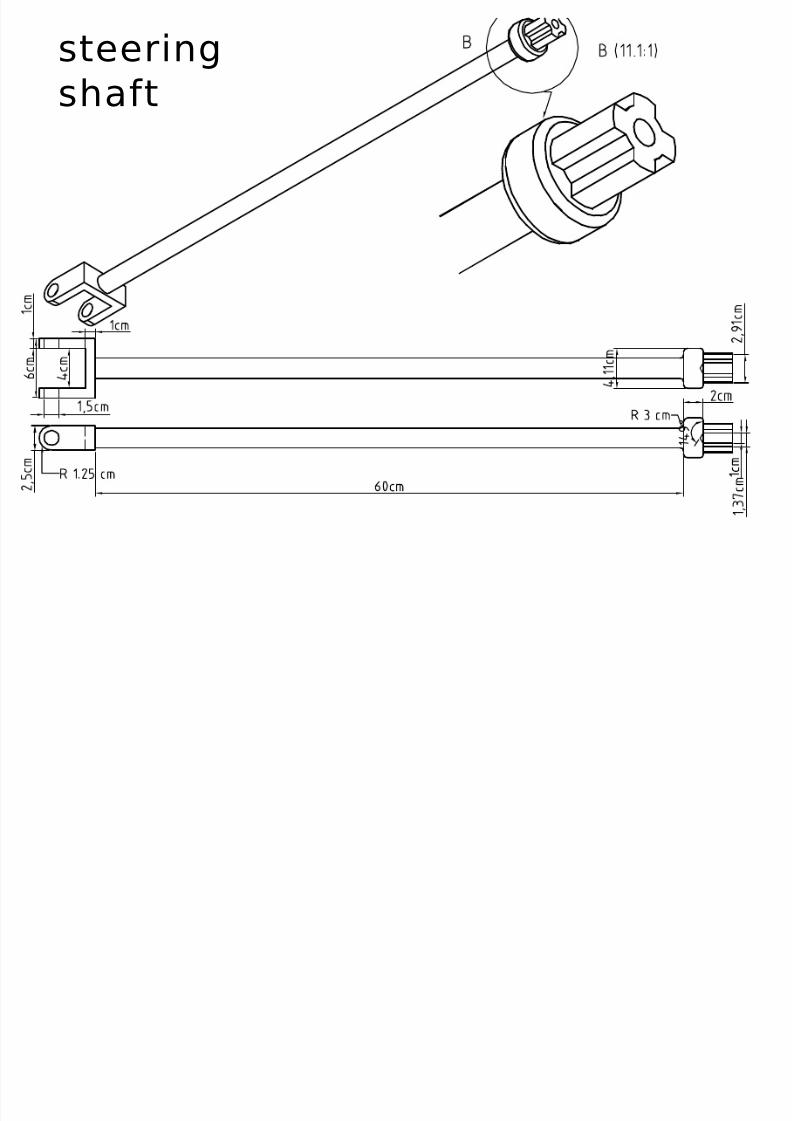
steering
shaft

8/12/2019 u-j-buggy
http://slidepdf.com/reader/full/u-j-buggy 61/74
pinion
8/12/2019 u-j-buggy
http://slidepdf.com/reader/full/u-j-buggy 62/74
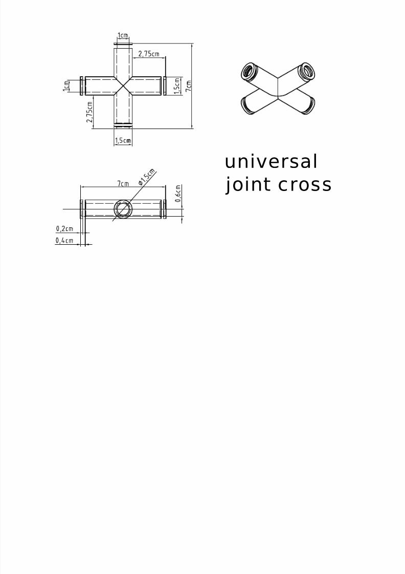
universal
joint cross
8/12/2019 u-j-buggy
http://slidepdf.com/reader/full/u-j-buggy 63/74
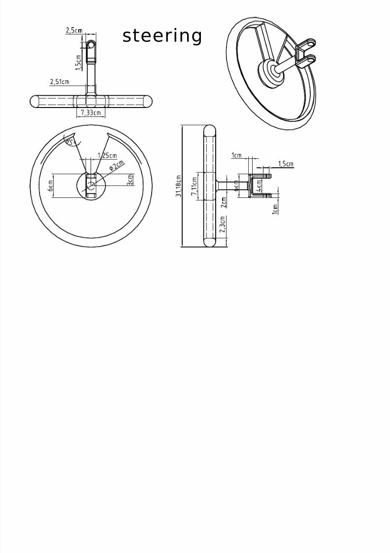
steering
8/12/2019 u-j-buggy
http://slidepdf.com/reader/full/u-j-buggy 64/74

8/12/2019 u-j-buggy
http://slidepdf.com/reader/full/u-j-buggy 65/74
assembly for the universal
joint connection with the
steering and the steering
shaft, which help in varying
the angle of the steering
relative to the steering shaft
the brown part is a
retaining ring
which help in
keeping the cross
in its place.

8/12/2019 u-j-buggy
http://slidepdf.com/reader/full/u-j-buggy 66/74
assembly for the
pinion and the
steering shaft
(connected together
using a HEX HEAD
MACHINE SCREW)

8/12/2019 u-j-buggy
http://slidepdf.com/reader/full/u-j-buggy 67/74
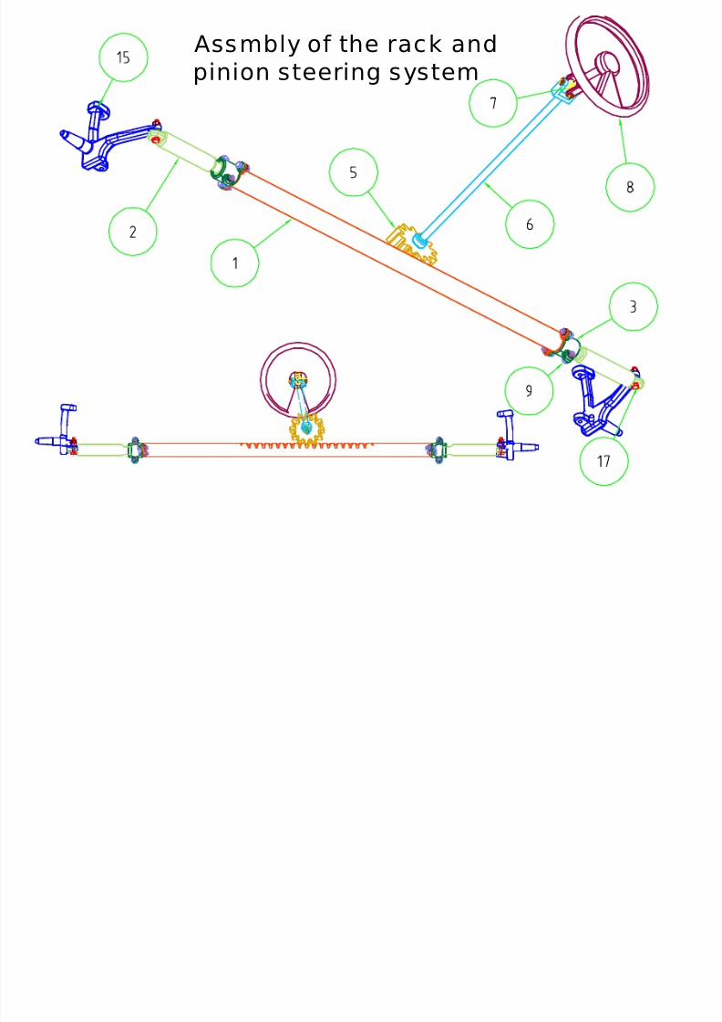
Assembly
of the
rack and
pinion

8/12/2019 u-j-buggy
http://slidepdf.com/reader/full/u-j-buggy 68/74
Assembly of the rack and the right
tie rod connected together using a
split able ball-socket

8/12/2019 u-j-buggy
http://slidepdf.com/reader/full/u-j-buggy 69/74
assmbly of the
tie rod
connection withthe axel ( the
figure also shoe
the axial
bearing
between tie rod
and axel)
Axial bearing which carry
the axial load between
the tie rod and the axel
and help in reducing the
friction
8/12/2019 u-j-buggy
http://slidepdf.com/reader/full/u-j-buggy 70/74
Assmbly of the rack and
pinion steering system

8/12/2019 u-j-buggy
http://slidepdf.com/reader/full/u-j-buggy 71/74
FASTENERS AND SCREWS FOR
THE STEERING MECHANISM

8/12/2019 u-j-buggy
http://slidepdf.com/reader/full/u-j-buggy 72/74
A future look.
This design data and analysis of is only a start in the long andcomplex way of designing and manufacturing a car, which couldcompete with other on road cars. But in my opinion no one can really
understand and add on the more complex mechanism without passthrough the starting point and understanding thoroughly the basic
functionality, and the theory behind the basic design. So this starting
point is the most essential factor in any designing process.
The next step in designing the complete car is to the design the
complete rear and front axles, then the back axe and transmission gear,which also includes the linkages between them. The selection of a motorwill help in both designing the gear transmission and the back axe. This
selection will include also a generator set, a battery set, an exhaust
system, gasoline tank and car accessories. Then will come the selection
for the right fasteners. After that will be the auditing process on all thedesigning processes which include a through checking of the design data
and measurements. Finally will be the manufacturing and assembling ofthe parts to form the complete car (product).
Conclusions & learned lessons
Two reasons make me choose this project. First is that cars
industry forms the major part in industry around the world, due to its
wide range of areas that is used in. Second is that the car it self form afertile environment of learning and studies for any mechanical engineer
with the various mechanical parts and systems it includes.
The project starts just from an idea of making a small, low cost
car, and then the project goes harmonically with the question (what is
the steps needed to make a car?). First, a shape for the car is needed tovisualize it in mind, then determining a specific function for the car help
in making decision of what will be the shape and what will be a better
design for the parts. The shape of the car require the design of thechassis, the chassis determine in bold lines the dimensions and the
capacity of the car. This lead for designing a suitable suspension system,
8/12/2019 u-j-buggy
http://slidepdf.com/reader/full/u-j-buggy 73/74
which could be built on that chassis, with taking in consideration that
the car will function as an off-road buggy car. The design of a
suspension system make it possible to design the steering system whichis essentially connected to the suspension system. And this was the last
step in this project hoping to continue the project later on.
I learned a lot from this project about how to synchronize my
work, and how to think scientifically and logically about every difficulty
that faced me. The project helps me also to learn how to make analysisto the problem in front me and how to choose the best solution for it.
The project also gave me the ability to have a wider and clearer look tothe theory behind mechanisms and help me to think how a mechanical
engineer should think.
I also had constructive skills in many mechanical engineeringsoftware and applications due to the working on the project such as
mechanical desktop, working model, cosmosm, AutoDesk inventor and
think design.
I had some minor troubles due to my inexperience in the realmechanical parts shapes, standards and means of connections, also
because of the unavailability of these parts in the university as theeducation here focus on the theory aspects only. Another problem faced
me in the long computation time for the software, especially in the finiteelement analysis processes, the assembling of the parts and the motion
analysis for the big mechanisms.
Finally, I would heartily thank Dr. Samer Mas’oud for hissupporting to me from the starting point in this project and for
accepting my basic concept and integrating it to an existing mechanism,
which would never have been done without his vital advices at the most
critical points. As I hope that, this project will meet your expectation tome.

8/12/2019 u-j-buggy
http://slidepdf.com/reader/full/u-j-buggy 74/74
References
References:
Theory of machines and mechanisms: JOHN JOSEPPH UI CKER, second
edition
Engineering graphics communication: BERTOLINE, WIEBE, MILLER,
third edition.
Mechanical engineering design: JOSEPH EDWARD SHIGLY, fif th
edition.
Engineering vibration: Daniel J. Inman
Mechanical desktop R4& 6 manual.
Working model FEA V6 for MDT manual.
Working model 4D V6 manual.
Cosmosm V2 manual.
Internet
www.howstuffworks.com
www.autorepair.about.com