Types of Flowmeters - Walter Scott, Jr. College of Engineeringpierre/ce_old/classes/CIVE 401/Team...
10
1 Types of Flowmeters Created By: Nick Alfino Matt Amidei Alwaleed Alomairah
-
Upload
truongkiet -
Category
Documents
-
view
219 -
download
4
Transcript of Types of Flowmeters - Walter Scott, Jr. College of Engineeringpierre/ce_old/classes/CIVE 401/Team...

1
Types of Flowmeters
Created By: Nick Alfino Matt Amidei Alwaleed Alomairah

2
Introduction
Flow measurement is vital to many different industries such as oil, power, water and wa ste treatmen t. These industries require that they know exactly how much fluid is passing through a point at any given point. Flowmeters help to determine how much fluid is passing through to determine how much money should be billed or how much product is being produced. A flowmeter is an instrument used to measure linear, non-‐linear, mass or volumetric flow rate of a liquid or gas.
Most flow meters work by forcing flow through a known confined space and measuring different properties to determine the flow rate of fluid. Examples of measured properties include pressure, thermal, magnetic, etc. In the report below, we will provide example for five different types of flowmeters. Most popular flowmeters include: Coriollis, Differential Pressure, Magnetic, Positive Displacement and Variable area. The most common type
of flowmeter is differential pressure and is pictured in Figure 3. The piezometers at the entrance and center measures the
incoming pressure used to determine the velocity of the flow. Background and History:
For thousands of years now, determining flow has been important to human culture and development. In ancient times, the Egyptians used the flow of the Nile River to determine how well their harvest for the year was going to go. Knowledge of the direction and velocity of both air and water has helped ancient navigators and early communities in their development of aqueducts.
The first major development in determining flow came from Swiss physicist Daniel Bernoulli in 1783. He determined that increasing the velocity of flowing fluid increases the kinetic energy while decreasing static energy. Bernoulli was able to relate the permanent pressure loss as the velocity head.
The next major development happened in 1831 by research form English scientist Michael Faraday. Faraday discovered that if a copper disk is rotated between the poles of a permanent magnet. Electromagnetic induction is the basis for operation of the magnetic flowmeter. If a liquid conductor move through a pipe of a know diameter through a magnetic
Figure 3 – Orifice Plate
Figure 1: Daniel Bernoulli
3
field, the induced voltage produced can be used to determine the velocity of the liquid.
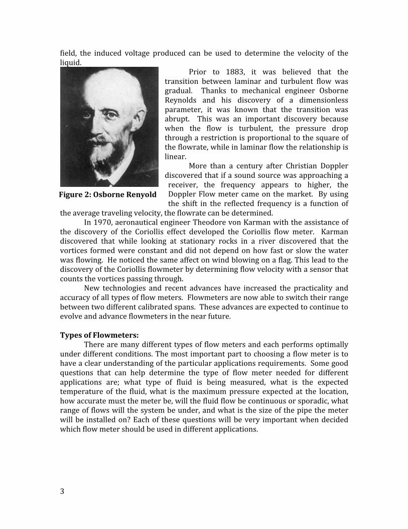
Prior to 1883, it was believed that the transition between laminar and turbulent flow was gradual. Thanks to mechanical engineer Osborne Reynolds and his discovery of a dimensionless parameter, it was known that the transition was abrupt. This was an important discovery because when the flow is turbulent, the pressure drop through a restriction is proportional to the square of the flowrate, while in laminar flow the relationship is linear.
More than a century after Christian Doppler discovered that if a sound source was approaching a receiver, the frequency appears to higher, the Doppler Flow meter came on the market. By using the shift in the reflected frequency is a function of
the average traveling velocity, the flowrate can be determined. In 1970, aeronautical engineer Theodore von Karman with the assistance of
the discovery of the Coriollis effect developed the Coriollis flow meter. Karman discovered that while looking at stationary rocks in a river discovered that the vortices formed were constant and did not depend on how fast or slow the water was flowing. He noticed the same affect on wind blowing on a flag. This lead to the discovery of the Coriollis flowmeter by determining flow velocity with a sensor that counts the vortices passing through.
New technologies and recent advances have increased the practicality and accuracy of all types of flow meters. Flowmeters are now able to switch their range between two different calibrated spans. These advances are expected to continue to evolve and advance flowmeters in the near future. Types of Flowmeters:
There are many different types of flow meters and each performs optimally under different conditions. The most important part to choosing a flow meter is to have a clear understanding of the particular applications requirements. Some good questions that can help determine the type of flow meter needed for different applications are; what type of fluid is being measured, what is the expected temperature of the fluid, what is the maximum pressure expected at the location, how accurate must the meter be, will the fluid flow be continuous or sporadic, what range of flows will the system be under, and what is the size of the pipe the meter will be installed on? Each of these questions will be very important when decided which flow meter should be used in different applications.
Figure 2: Osborne Renyold

4
This section is going to discuss the most common types of flowmeters including; • Differential Pressure Flow Meters • Positive Displacement Flow Meters • Open Channel Flow Meters • Electromagnetic Flow Meters
It will also identify the major advantage and disadvantages of each flow meter when necessary. Differential Pressure Flow Meters
Differential pressure flow meters operate by introducing a restriction in the cross sectional area of a flowing fluid. Restricting the flow area causes a pressure drop across the constriction, this pressure drop is cause by a change in the fluids velocity. The operating principal is based on the Bernoulli equation and the continuity equation of fluid flow, combining these equations you can find the relationship between the flow rate and pressure drop. This theory can be seen below. Bernoulli’s equation can be written as
𝑃! +𝜌𝑉!!
2 + 𝛾𝑍! = 𝑃! +𝜌𝑉!!
2 + 𝛾𝑍! We assume the flow is horizontal
𝑍! = 𝑍! And the Bernoulli equation becomes
𝑃! +𝜌𝑉!!
2 = 𝑃! +𝜌𝑉!!
2 We also assume the velocity profiles are uniform at sections 1 and 2. The
continuity equation and be written as 𝑄 = 𝐴!𝑉! = 𝐴!𝑉!
Where 𝐴! is the smaller flow area 𝐴! < 𝐴! . Combining these equations gives and equation for the flow rate in the pipe.
𝑄 = 𝐴!2 𝑃! − 𝑃!
𝜌 1− 𝐴!𝐴!
!
The most common types of differential pressure flow meters are: • Orifice Plates
An orifice plate is a plate with a circular hole in the middle of it. When fluid flows through the hole, the velocity will increase and the pressure will decrease. Orifice plates are commonly used when the flow is continuous and occupies the entire pipe.

5
Figure 1. Example of an Orifice Plate; (Engineering ToolBox, 2010)
• Flow Nozzles
A Flow Nozzle is very similar to an orifice plate, the main difference is that flow nozzles have a gradual constriction rather than the abrupt constriction of an orifice plate. Flow nozzles are common for high velocity, low viscosity flows. Flow nozzles also have a greater flow capacity when compared to other differential pressure meters.
Figure 2. Example of a Flow Nozzle; (Engineering ToolBox, 2010)
• Venturi Tubes
Venturi tubes are very common differential pressure flow meters because of their simplicity and high pressure and energy recovery. Venturi tubes are very accurate over wide flow ranges and the gradual contraction and expansion reduces the drag and allows for a low pressure loss.
Figure 3. Example of a Venturi Tube; (Engineering Toolbox, 2010)
• Rotameters (Variable Area)
Rotameters require a vertically oriented transparent pipe with a larger opening at the top than the bottom. A float is then placed in the pipe and the upward fluid flow causes the float to rise. Once the float has reached equilibrium, upward pressure and buoyancy forces equal the gravitational forces, the flow rate can be calculated.

6
Figure 4. Example of a Rotameter; (Engineering ToolBox, 2010)
Positive Displacement Flow Meters Positive displacement flow meters are the only family of flow meters that
directly measure the volume of fluid passing through a pipe. This is achieved by passing a specific amount of fluid with each rotation of the meter. A good analogy on how these work is to imagine filling a bucket and dumping it numerous times to measure the amount of water. Positive displacement flow meters are very accurate regardless of the fluids viscosity, density, velocity, or temperature. Because of the accuracy and ease of use, positive displacement flow meters are commonly used for domestic water measurement. The main types of positive displacement flow meters are:
• Piston Flow Meters
Piston flow meters or rotary piston displacement meters are most commonly used for domestic water measurement in the UK and are very common in pipes 1.5 in or less (Max, 2010). They operate by having a piston rotate in a chamber with a known volume. Every rotation the piston makes passes a volume of water equivalent to the chambers known volume down the pipe. Knowing the number of rotations and the volume of the chamber allows the flow rate to be calculated.
Figure 5. Example of a Piston Flow Meter; (MaxTools, 2010)
• Gear Flow Meters
Gear flow meters consist of two round gears that are mounted in overlapping compartments. When a fluid flows through the inlet it gets trapped in the teeth of

7
the gear and is transported to the outlet. Knowing the volume of the voids between the teeth and the wall and the number of rotation, the flow rate can be calculated.
Figure 6. Example of a Gear Flow Meter; (MaxTools, 2010)
• Helical Flow Meters
Helical or helical gear flow meters operate using the same principal of the previous displacement flow meters. As the fluid flows through the inlet it causes the helix shaped structure to rotate. As the meter rotates it traps a known amount of fluid in the rotors, this fluid is then released towards the outlet. Knowing the speed of rotation and the volume between the rotors, the flow rate is calculated.
Figure 7. Example of a Helical Flow Meter; (MaxTools, 2010)
Open Channel Flow Meters
Open channel flow occurs when part of the flowing fluid is open to the free surface. Because of this the cross section of the flow is determined by the shape and depth of the channel or pipe that the fluid is flowing through. This inconsistency in area makes it difficult to calculate the flow compared to fixed area flows such as pressurized pipe flow. Below are the most common types of open channel flow meters and a description on how each one works.
• Flumes
Flumes are specifically shaped structures that are placed in the flowing fluid. Under free flow the flume forces the flow to accelerate in a way that can be characterized by known relationships between the head of the fluid, and the fluids flow rate. Flumes generally consist of three sections; the inlet, the throat, and the diverging exit. The purpose of the inlet is to collect the channel flow and direct it into the throat of the flume. The throat is the narrowest part of the flume and this is where the waters velocity is increased. The purpose of the diverging exit is to minimize downstream disturbances in the flow and reduce the fluid velocity back to its original velocity.

8
Figure 8. Example of an Open Channel Flume; (Streamflow, 2003)
• Weir
Weirs are generally structures that are placed as an obstruction in the fluid flow such as a dam with a special shaped opening at the top. When the weir is placed perpendicular to the flow its causes the fluid level to rise, this rise is usually recorded by a device upstream of the weir. Knowing the increase in head, the flow rate over the weir can be calculated.
Figure 9. Example of an Open Channel Weir; (Engineering ToolBox, 2009)
• Sluice Gate
A sluice gate is very similar to a weir for measuring open channel flows. The only difference is the opening for the fluid is placed at the bottom of the obstruction rather than the top. Sluice gates are also commonly used to regulate the amount of flow passing through them. The head of the fluid preceding the sluice gate can be measured using devices upstream and the fluids flow rate can then be calculated.
Figure 10. Example of an Open Channel Sluice Gate; (Engineering ToolBox, 2004)
9
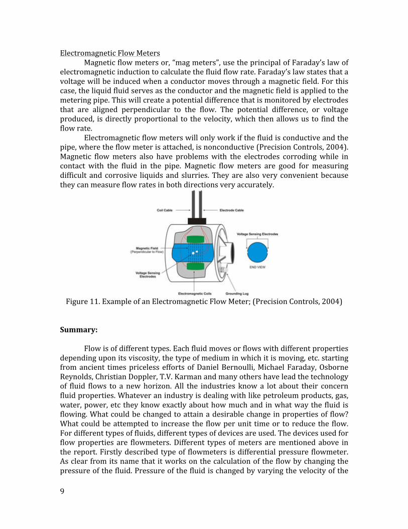
Electromagnetic Flow Meters Magnetic flow meters or, “mag meters”, use the principal of Faraday’s law of
electromagnetic induction to calculate the fluid flow rate. Faraday’s law states that a voltage will be induced when a conductor moves through a magnetic field. For this case, the liquid fluid serves as the conductor and the magnetic field is applied to the metering pipe. This will create a potential difference that is monitored by electrodes that are aligned perpendicular to the flow. The potential difference, or voltage produced, is directly proportional to the velocity, which then allows us to find the flow rate.
Electromagnetic flow meters will only work if the fluid is conductive and the pipe, where the flow meter is attached, is nonconductive (Precision Controls, 2004). Magnetic flow meters also have problems with the electrodes corroding while in contact with the fluid in the pipe. Magnetic flow meters are good for measuring difficult and corrosive liquids and slurries. They are also very convenient because they can measure flow rates in both directions very accurately.
Figure 11. Example of an Electromagnetic Flow Meter; (Precision Controls, 2004)
Summary:
Flow is of different types. Each fluid moves or flows with different properties depending upon its viscosity, the type of medium in which it is moving, etc. starting from ancient times priceless efforts of Daniel Bernoulli, Michael Faraday, Osborne Reynolds, Christian Doppler, T.V. Karman and many others have lead the technology of fluid flows to a new horizon. All the industries know a lot about their concern fluid properties. Whatever an industry is dealing with like petroleum products, gas, water, power, etc they know exactly about how much and in what way the fluid is flowing. What could be changed to attain a desirable change in properties of flow? What could be attempted to increase the flow per unit time or to reduce the flow. For different types of fluids, different types of devices are used. The devices used for flow properties are flowmeters. Different types of meters are mentioned above in the report. Firstly described type of flowmeters is differential pressure flowmeter. As clear from its name that it works on the calculation of the flow by changing the pressure of the fluid. Pressure of the fluid is changed by varying the velocity of the

10
fluid. Some hindrance is introduced in the path of flow to increase the velocity. Differential pressure flow meters are based on Bernoulli’s equation and continuity equation of flow. Orifice plates, flow nozzles, Venturi tubes and Rotameters are used in differential pressure flowmeters. These all devices are used on a single principal of reducing the area of flow to increase the speed of flow although there are different shapes used to reduce the area of flow. Second type of flow meters is positive displacement flow meters. Contrary to the differential pressure flow meters, these flowmeters measures the flow of a fluid directly by the volume of the fluid passing through a unit known area in unit time. Piston, gear and helical flow meters are all devices which calculates the flow by the help of moving piston, gear or helical in a chamber of known volume. The amount of fluid passed by one complete cycle of the piston gear or helical shaft is equal to the volume of the known chamber volume. In this way the amount of flow is calculated in the unit time. These two types can be used for the calculation of flow of some fluid in some closed shaft or pipe, etc. Sometimes fluid flowing in some open channel is needed to be observed and measurements of different flow properties are required. For this sort of fluid flow, open channel flow meters are used. The shape of the channel describes the way of calculating the volume of fluid flowing through that channel. The depth and width of the channel in case of the rectangular channel effects the calculation. On the other hand radius affects the circular channel. However, a channel with varying area or volume could be different to calculate and difficult. With different shapes, flumes, weir and sluice gate flow meters measures the flowrate by measuring the amount of fluid flowing through the known area opening in a unit time. Sluice gate and weir channel flow meters are quiet same in their working principle for measuring flow rate. Just the difference is the presence of opening. Weirs have opening at some height but the sluice gate allows flow from its bottom. The last type of flow meters is somewhat advanced and based on the Faraday’s law of electromagnetic induction. However it is advanced, but also has some restrictions. Electromagnetic flow meters can only work if the fluid is conductive and the flow pipe is non-‐conductive. References: Positive Displacement Flow meter Technology. (2012, January 1). Retrieved November 10, 2014. Weirs -‐ Flow Rate Measure. (2009, March 29). Retrieved November 10, 2014. Flumes for Measuring the Flow of Water in Open Channels. (2014, January 1). Retrieved November 10, 2014. Positive Displacement Flow Meters. (2010, June 1). Retrieved November 10, 2014. Sluice Gate Flow Measurements. (2004, October 16). Retrieved November 10, 2014. Streamflow. (2003, June 28). Retrieved November 10, 2014.