TYPE K TEMPORARY CONCRETE BARRIER SYSTEM · shall be ASTM A 706 except that a 2 ... All...
15
07/01/10 414 1 TYPE K TEMPORARY CONCRETE BARRIER SYSTEM 12/ 30/ 2011 11: 42: 28 AM REVI SI ON C:\ d\ pr o j ec t s \ s t andar ds \ r o adway \ 00400- s \ 00414- 01. dgn NO. SHEET NO. INDEX r d960r h DESCRIPTION: REVISION LAST FY 2012/2013 FDOT DESIGN STANDARDS weight of one unit equals 2.7 tons. HANDLING: At no time shall the Barrier Units be lifted or moved by use of Bars 6D that extend from the ends of the units. Approximate - Date of manufacture (day, month and year) - Fabricator’s name or symbol - Type K1 and figures a minimum of 0.5" tall. Ink stamps are not allowed. Permanently mark with the following information: MARKING: Permanently mark the top left end of each Barrier Unit by the use of an embedded and anchored metallic plate with letters floating in lieu of the General Surface Finish. Use stationary metal forms or stationary timber forms with a form liner. of the Barrier Units with a General Surface Finish. Finish the bottom of the Barrier Units to a dense uniform surface by SURFACE FINISH: Construct Barrier Units in accordance with Specification Sections 400 and 521. Finish the top and sides with ASTM A 53. Hot-dip galvanize the Lifting Sleeve Assemblies after their fabrication in accordance with the Specifications. LIFTING SLEEVE ASSEMBLY: Inclusion of the Lifting Sleeve Assemblies is optional. Steel for Pipe Sleeve shall be in accordance All dimensions in the Bending Diagrams are out to out. All reinforcing steel shall have a 2" minimum cover except as noted. may be utilized in lieu of Bars 4A and 5B. At the option of the Fabricator, Deformed Welded Wire Fabric in accordance with ASTM A 497 and the details shown on Sheet 2 Correct placement of Bars 6D is critical for proper fit up and performance of individual Barrier Units. »¿Fabricator’s option, the entire length of Bars 6D may be galvanized or coated. Install Bars 6D within ˘" of the plan dimensi accordance with Specification Section 975. The minimum limit of galvanizing or coating is shown in the Bending Diagrams. At the of Bars 6D shall be hot dip galvanized in accordance with Specification Section 962 or coated with a cold galvanizing compound in »¿shall be ASTM A 706 except that a 2˘" diameter pin must be used for the 180 degree bend test. After fabrication, all or REINFORCING STEEL: All reinforcing steel shall be ASTM A 615, Grade 60 except for Bars 6D1, 6D2 and 6D3. Bars 6D1, 6D2 and 6D3 are not applicable. Barrier Units represented by concrete acceptance strength tests which fall below 5000 psi will be rejected. CONCRETE: Concrete shall be Class IV in accordance with Specification Section 346. Specification Sections 346-10.2 through 346-10.4 Specification Section 450 or in a precast plant meeting the requirements of Specification Section 6-8. FABRICATOR PREQUALIFICATION: The Barrier Units shall be made in a prestressed concrete plant that meets the requirements of FABRICATION NOTES: keeper pins, or guardrail components for installing Type K Barrier Units. different type, size, length or material grade anchor bolts, nuts, washers, adhesives, connector pins, stakes, types of reinforcing steel for those shown for constructing Type K Barrier Units. Also, do not substitute In order to maintain crashworthiness of the system, do not substitute different grades, sizes, shapes or and installation materials as shown. configurations as shown utilizing the types, sizes, lengths, shapes, strengths and grades of the fabrication or structurally evaluated to meet the requirements of NCHRP Report 350 TL-3 criteria for the installation The Type K Temporary Concrete Barrier System has been crash tested to NCHRP Report 350 TL-3 criteria
Transcript of TYPE K TEMPORARY CONCRETE BARRIER SYSTEM · shall be ASTM A 706 except that a 2 ... All...
07/01/10 414 1
TYPE K TEMPORARY CONCRETE BARRIER SYSTEM
12/30/2011
11:4
2:2
8
AM
RE
VISIO
N
C:\
d\projects\standards\road
way\00400-s\00414-01.d
gn
NO.
SHEET
NO.
INDEX
rd960rh
DESCRIPTION:
REVISION
LAST
FY 2012/2013
FDOT DESIGN STANDARDS
weight of one unit equals 2.7 tons.
HANDLING: At no time shall the Barrier Units be lifted or moved by use of Bars 6D that extend from the ends of the units. Approximate
- Date of manufacture (day, month and year)
- Fabricator’s name or symbol
- Type K1
and figures a minimum of 0.5" tall. Ink stamps are not allowed. Permanently mark with the following information:
MARKING: Permanently mark the top left end of each Barrier Unit by the use of an embedded and anchored metallic plate with letters
floating in lieu of the General Surface Finish. Use stationary metal forms or stationary timber forms with a form liner.
of the Barrier Units with a General Surface Finish. Finish the bottom of the Barrier Units to a dense uniform surface by
SURFACE FINISH: Construct Barrier Units in accordance with Specification Sections 400 and 521. Finish the top and sides
with ASTM A 53. Hot-dip galvanize the Lifting Sleeve Assemblies after their fabrication in accordance with the Specifications.
LIFTING SLEEVE ASSEMBLY: Inclusion of the Lifting Sleeve Assemblies is optional. Steel for Pipe Sleeve shall be in accordance
All dimensions in the Bending Diagrams are out to out. All reinforcing steel shall have a 2" minimum cover except as noted.
may be utilized in lieu of Bars 4A and 5B.
At the option of the Fabricator, Deformed Welded Wire Fabric in accordance with ASTM A 497 and the details shown on Sheet 2
Correct placement of Bars 6D is critical for proper fit up and performance of individual Barrier Units.
Fabricator’s option, the entire length of Bars 6D may be galvanized or coated. Install Bars 6D within ˘�" of the plan dimensi
accordance with Specification Section 975. The minimum limit of galvanizing or coating is shown in the Bending Diagrams. At the
of Bars 6D shall be hot dip galvanized in accordance with Specification Section 962 or coated with a cold galvanizing compound in
shall be ASTM A 706 except that a 2˘�" diameter pin must be used for the 180 degree bend test. After fabrication, all or
REINFORCING STEEL: All reinforcing steel shall be ASTM A 615, Grade 60 except for Bars 6D1, 6D2 and 6D3. Bars 6D1, 6D2 and 6D3
are not applicable. Barrier Units represented by concrete acceptance strength tests which fall below 5000 psi will be rejected.
CONCRETE: Concrete shall be Class IV in accordance with Specification Section 346. Specification Sections 346-10.2 through 346-10.4
Specification Section 450 or in a precast plant meeting the requirements of Specification Section 6-8.
FABRICATOR PREQUALIFICATION: The Barrier Units shall be made in a prestressed concrete plant that meets the requirements of
FABRICATION NOTES:
keeper pins, or guardrail components for installing Type K Barrier Units.
different type, size, length or material grade anchor bolts, nuts, washers, adhesives, connector pins, stakes,
types of reinforcing steel for those shown for constructing Type K Barrier Units. Also, do not substitute
In order to maintain crashworthiness of the system, do not substitute different grades, sizes, shapes or
and installation materials as shown.
configurations as shown utilizing the types, sizes, lengths, shapes, strengths and grades of the fabrication
or structurally evaluated to meet the requirements of NCHRP Report 350 TL-3 criteria for the installation
The Type K Temporary Concrete Barrier System has been crash tested to NCHRP Report 350 TL-3 criteria

07/01/07 414 2
TYPE K TEMPORARY CONCRETE BARRIER SYSTEM
12/30/2011
11:4
2:2
9
AM
RE
VISIO
N
C:\
d\projects\standards\road
way\00400-s\00414-02.d
gn
NO.
SHEET
NO.
INDEX
rd960rh
DESCRIPTION:
REVISION
LAST
FY 2012/2013
FDOT DESIGN STANDARDS
to outside edge of Bars 6D.
Measured from end of Barrier Unit
CONCRETE BARRIER QUANTITIES
ESTIMATED TEMPORARY
ASSEMBLY DETAIL (OPTIONAL)
LIFTING SLEEVE
shown for clarity)
(Reinforcement not
SECTION D-D
Section C-C see Sheet 3.
For Section A-A, Section B-B and
Cross References:
Bars 4A1
Bar 6D3
Bar 6D2
Bar 6D1
(both sides) (Typ.)
Anchor Blockout
Bars 6C Bars 6C Bars 6C
" Chamfer (Typ.)21(Optional) with
2" Ø Lifting Sleeve Assembly
Bar 4A2
(Typ.)
clear Bars 6D)
Bars 4E (Bend to
Bars 4A1
Bars 5B
Optional Sp. used)
Bar 4A2 (Omit if
Bars 4A1
Bar 6D1
Bar 6D2
Bar 6D3
Bars 4A1
Bars 6D
Bar 6C
Bar 6C Bar 4A1 Bars 5B
Bar 4A2
clear Bars 6D) (Typ.)
Bars 4E (Bend to
Bar 4A1Bar 4A1 Bar 6C
" Chamfer (Typ.)21with
2" Ø Lifting Sleeve Assembly
Bar 4A2
Bar 6C Bar 6C
(Typ.)
Anchor Blockout
Bar 6CBar 4A1
Bars 4A1
Bars 6D
â�� 2" ˆ
2" Ø Hole
(2"
NPS)
Pipe Sleev
e
Bars 4
E
3"
(Typ.)
3’-0"
6"
1’-
5"
2’-
8"
3"
6"
*
"212 sp. @ 8
3’-3"
10""211’-8
1’-1"1’-3"1’-1"
"211’-810"
6’-0"
Optional Spacing
Bars 4A (Typ.)
"211’-8
(Typ.)
1’-
0"
"211’-810"
3’-3"
"212 sp. @ 8
Marked End
(see Note)
2"
41
2
"419
"412
"434
3"
4"
5"
4"
3"
5"
"2
11’-
10
"4
111
"4
111
2’-0"4’-3"2’-0" 4’-3"
12’-6"
ELEVATION VIEW
C B
BCA
A
SECTION THRU LIFT/DRAIN SLOT
ANCHOR BLOCKOUT DETAIL
D
D
PLAN VIEW
ITEM UNIT QUANTITY
Concrete
Reinforcing Steel
The above quantities are for one Barrier Unit.
LB
CY 1.29
218
Slot
3"
2’-3" (Lift/Drain Slot)3’-0" 2’-0" 2’-3" (Lift/Drain Slot)
"2
14
3"
1’-
5"
"2
17
"81–
"85*3
Cha
mfer
1"
Top
Chamfer
" Side431
2" Spacing Bars 4A
"81–
"85*3

07/01/07 414 3
TYPE K TEMPORARY CONCRETE BARRIER SYSTEM
12/30/2011
11:4
2:2
9
AM
RE
VISIO
N
C:\
d\projects\standards\road
way\00400-s\00414-03.d
gn
NO.
SHEET
NO.
INDEX
rd960rh
DESCRIPTION:
REVISION
LAST
FY 2012/2013
FDOT DESIGN STANDARDS
(SECTION B-B SIMILAR)
SECTION A-A (SHOWN)
(Bars 6D not shown for clarity)
SECTION C-C
BARS 6D1, 6D2 & 6D3
SIDE VIEW
BARS 6D1, 6D2 & 6D3
TOP VIEW
(CONVENTIONAL STEEL)
DRAIN SLOTS
NO. 4 BAR OVER
(CONVENTIONAL STEEL)
NO. 4 TYPICAL BAR
(CONVENTIONAL STEEL)
DRAIN SLOTS
NO. 4 BAR OVER
(Typ.)
55°
View, Sheet 2. Field trim D 17.2’s to clear drain slots by 2".
D 17.2 spacing shall match spacings for Bars 4A shown in Elevation
Reinforcement cage as shown.
Place 2 ~ No. 5 Bars (12’-3" long) in bottom of Welded Wire
NOTES:
(Typ.)
55°
vertical bar)
D 17.2 (Typ.
(Typ.)
D 15.5
Bends
(Typ.) all
2" Ø Pin
(Conventional Steel)
2 ~ No. 5 Bars
placed with D 17.2’s
slots (Conventional Steel),
No. 4 Bar over drain
(Typ.)
55°
(Typ.)
55°
D 19.7
Pin
4" Ø
(Typ.)
D 15.5
" –417
except over drain slots
placed with D 19.7’s
(Conventional Steel),
No. 4 Typical Bar
placed with D 19.7’
slots (Conventional Steel),
No. 4 Bar over drain
D 6.3 (2 required)
(Conventional Steel)
2 ~ No. 5 Bars
Sheet 2. Field trim D 19.7’s to clear drain slots by 2".
D 19.7 spacing shall match spacings for Bars 4A shown in Elevation View,
Reinforcement cage as shown.
Place 2 ~ No. 5 Bars (12’-3" long) in bottom of Welded Wire
NOTES:
" Ø Pin216
" Ø Pin432
8" Min. (Limit of Galvanizing)
" Ø Pin214
55°55°
" Ø Pin414
2" Ø Pin
" Ø Pin414
2" Ø Pin
of Barrier.
top and bottom corners
" Chamfer at 43 Provide
NOTE:
Bars 4A1
(Marked end shown)
Bars 6D (Typ.)
(Typ.)
Bars 5B
to 2" Ø Holes (Typ.)
" Cover - Bars 6C 21
Bar 4A2
(Typ.)
Bars 5B
(see Detail)
Bars 4E
" Chamfer21Assembly with
2" Ø Lifting Sleeve
Bars 6C
(see Detail)
Anchor Blockout
1’-4"
8"
"2
12
STIRRUP BAR 4A2STIRRUP BAR 4A1
BAR 4E
BAR 6C
BILL OF REINFORCING STEEL
CONVENTIONAL REINFORCING STEEL BENDING DIAGRAMS
WELDED WIRE REINFORCEMENT
ALTERNATE REINFORCING STEEL DETAIL
CONFIGURATION ONE
CONFIGURATION TWO
MARK SIZE NUMBER LENGTH
6’-1"104A1
A2
B
C
D1
D2
D3
E 4
6
6
6
6
5
4 2
5
6
2
2
2
4 2’-0"
8’-6"
7’-6"
8’-4"
3’-1"
12’-3" (Straight)
5’-5"
1’-0"
7"
"213 "2
13"214"2
14
"8
52
8"
6" 11°30’ 1’-
9"
7""
21
4
6"
1’-4"
6"
7"
1’-0"
1’-4"
10" "
21
4"
21
6"
43
1
2’-
2"
11°30’
"2
14
"432’-9
2’-9"
"212’-10
6D1
6D2
6D3
1’-0
" (Typ.)
1’-
4" (6
D1)
1’-
0" (6
D2)
1’-
4" (6
D3)90°
"213 "2
14 "214 "2
13
1’-
9"
6" 6"
7"
11°30’
11°30’
"211 "2
14 "214 "2
11
1’-
9"
"4
14
"215 "2
15
"8
51’-
2"
87
2
1’-
10"
2’-
8"
7"
3"
"2
16
8"
5" "412 8" "4
12 5"
"211’-10
"4111 "4
111
10" R
Cover top
2"
Min.
(Min.) sides
" Cover43
1
Cover botto
m
2"
Min.
5" "412 8" "4
12 5"
"211’-10
"8
72
"8
51’-
2
1’-
10"
2’-
8"
7"
3"
"2
16
8"
10" R
Cover top
2"
Min.
botto
m
2"
Cover
(Min.) sides
" Cover43
1
1’-
0"
01/01/11 414 4
TYPE K TEMPORARY CONCRETE BARRIER SYSTEM
12/30/2011
11:4
2:3
0
AM
RE
VISIO
N
C:\
d\projects\standards\road
way\00400-s\00414-04.d
gn
NO.
SHEET
NO.
INDEX
rd960rh
DESCRIPTION:
REVISION
LAST
FY 2012/2013
FDOT DESIGN STANDARDS
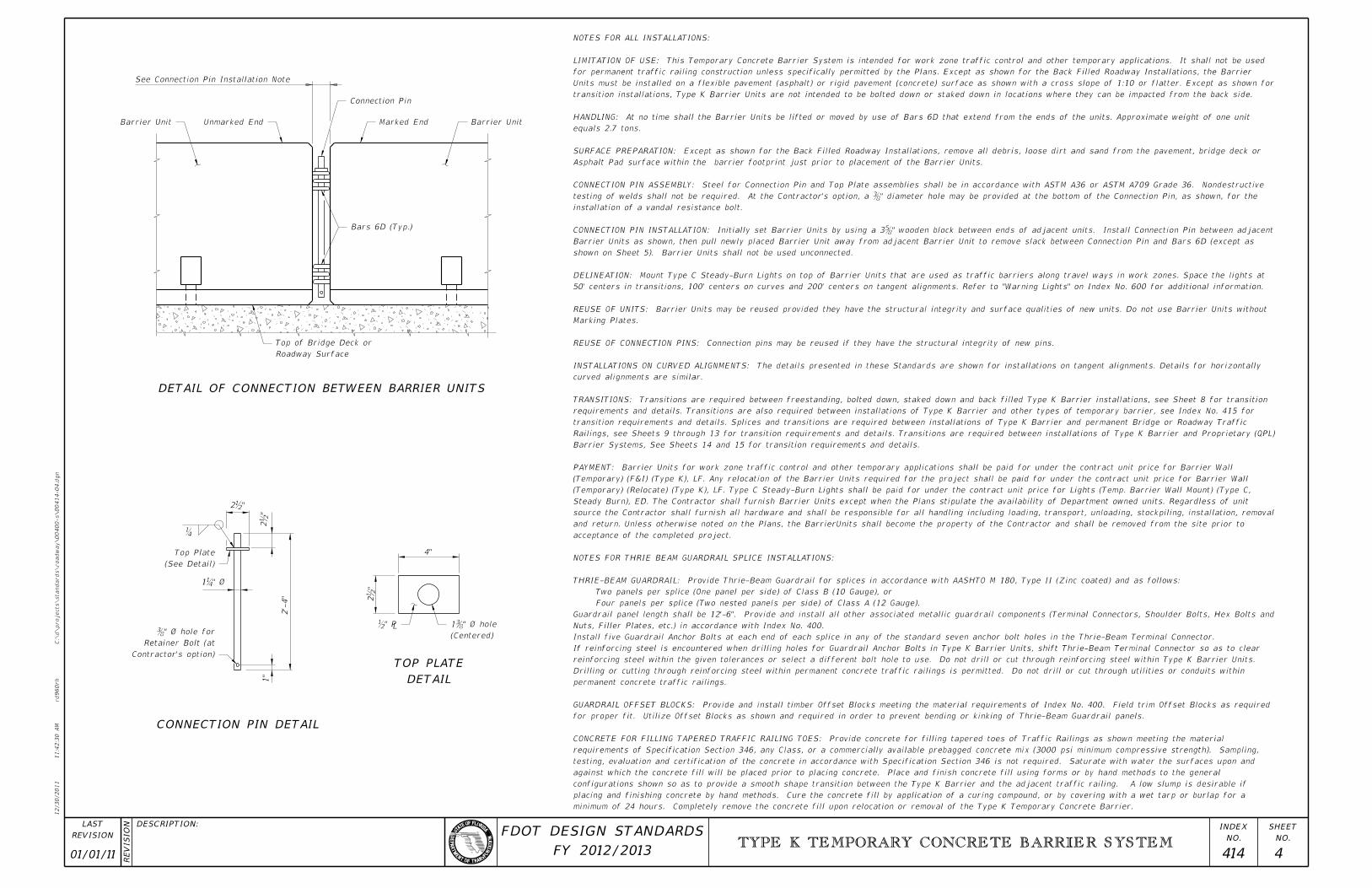
DETAIL
TOP PLATE
Barrier Unit Unmarked End Barrier UnitMarked End
Connection Pin
Bars 6D (Typ.)
Roadway Surface
Top of Bridge Deck or
(Centered)
1˘�" ˆ��»¿?
Contractor’s option)
Retainer Bolt (at
˘�" ˆ� hole
(See Detail)
Top Plate
See Connection Pin Installation Note
2b"
2b"
�
2’-
4"
1"
2b"
4"
1˘
CONNECTION PIN DETAIL
DETAIL OF CONNECTION BETWEEN BARRIER UNITS
minimum of 24 hours. Completely remove the concrete fill upon relocation or removal of the Type K Temporary Concrete Barrier.
placing and finishing concrete by hand methods. Cure the concrete fill by application of a curing compound, or by covering with a wet tarp or burlap for a
configurations shown so as to provide a smooth shape transition between the Type K Barrier and the adjacent traffic railing. A low slump is desirable if
against which the concrete fill will be placed prior to placing concrete. Place and finish concrete fill using forms or by hand methods to the general
testing, evaluation and certification of the concrete in accordance with Specification Section 346 is not required. Saturate with water the surfaces upon and
requirements of Specification Section 346, any Class, or a commercially available prebagged concrete mix (3000 psi minimum compressive strength). Sampling,
CONCRETE FOR FILLING TAPERED TRAFFIC RAILING TOES: Provide concrete for filling tapered toes of Traffic Railings as shown meeting the material
for proper fit. Utilize Offset Blocks as shown and required in order to prevent bending or kinking of Thrie-Beam Guardrail panels.
GUARDRAIL OFFSET BLOCKS: Provide and install timber Offset Blocks meeting the material requirements of Index No. 400. Field trim Offset Blocks as required
permanent concrete traffic railings.
Drilling or cutting through reinforcing steel within permanent concrete traffic railings is permitted. Do not drill or cut through utilities or conduits within
reinforcing steel within the given tolerances or select a different bolt hole to use. Do not drill or cut through reinforcing steel within Type K Barrier Units.
If reinforcing steel is encountered when drilling holes for Guardrail Anchor Bolts in Type K Barrier Units, shift Thrie-Beam Terminal Connector so as to clear
Install five Guardrail Anchor Bolts at each end of each splice in any of the standard seven anchor bolt holes in the Thrie-Beam Terminal Connector.
Nuts, Filler Plates, etc.) in accordance with Index No. 400.
Guardrail panel length shall be 12’-6". Provide and install all other associated metallic guardrail components (Terminal Connectors, Shoulder Bolts, Hex Bolts and
Four panels per splice (Two nested panels per side) of Class A (12 Gauge).
Two panels per splice (One panel per side) of Class B (10 Gauge), or
THRIE-BEAM GUARDRAIL: Provide Thrie-Beam Guardrail for splices in accordance with AASHTO M 180, Type II (Zinc coated) and as follows:
NOTES FOR THRIE BEAM GUARDRAIL SPLICE INSTALLATIONS:
acceptance of the completed project.
and return. Unless otherwise noted on the Plans, the BarrierUnits shall become the property of the Contractor and shall be removed from the site prior to
source the Contractor shall furnish all hardware and shall be responsible for all handling including loading, transport, unloading, stockpiling, installation, removal
Steady Burn), ED. The Contractor shall furnish Barrier Units except when the Plans stipulate the availability of Department owned units. Regardless of unit
(Temporary) (Relocate) (Type K), LF. Type C Steady-Burn Lights shall be paid for under the contract unit price for Lights (Temp. Barrier Wall Mount) (Type C,
(Temporary) (F&I) (Type K), LF. Any relocation of the Barrier Units required for the project shall be paid for under the contract unit price for Barrier Wall
PAYMENT: Barrier Units for work zone traffic control and other temporary applications shall be paid for under the contract unit price for Barrier Wall
Barrier Systems, See Sheets 14 and 15 for transition requirements and details.
Railings, see Sheets 9 through 13 for transition requirements and details. Transitions are required between installations of Type K Barrier and Proprietary (QPL)
transition requirements and details. Splices and transitions are required between installations of Type K Barrier and permanent Bridge or Roadway Traffic
requirements and details. Transitions are also required between installations of Type K Barrier and other types of temporary barrier, see Index No. 415 for
TRANSITIONS: Transitions are required between freestanding, bolted down, staked down and back filled Type K Barrier installations, see Sheet 8 for transition
curved alignments are similar.
INSTALLATIONS ON CURVED ALIGNMENTS: The details presented in these Standards are shown for installations on tangent alignments. Details for horizontally
REUSE OF CONNECTION PINS: Connection pins may be reused if they have the structural integrity of new pins.
Marking Plates.
REUSE OF UNITS: Barrier Units may be reused provided they have the structural integrity and surface qualities of new units. Do not use Barrier Units without
50’ centers in transitions, 100’ centers on curves and 200’ centers on tangent alignments. Refer to "Warning Lights" on Index No. 600 for additional information.
DELINEATION: Mount Type C Steady-Burn Lights on top of Barrier Units that are used as traffic barriers along travel ways in work zones. Space the lights at
shown on Sheet 5). Barrier Units shall not be used unconnected.
Barrier Units as shown, then pull newly placed Barrier Unit away from adjacent Barrier Unit to remove slack between Connection Pin and Bars 6D (except as
CONNECTION PIN INSTALLATION: Initially set Barrier Units by using a 3˘�" wooden block between ends of adjacent units. Install Connection Pin between adjac
installation of a vandal resistance bolt.
testing of welds shall not be required. At the Contractor’s option, a ˘�" diameter hole may be provided at the bottom of the Connection Pin, as shown, for
CONNECTION PIN ASSEMBLY: Steel for Connection Pin and Top Plate assemblies shall be in accordance with ASTM A36 or ASTM A709 Grade 36. Nondestructive
Asphalt Pad surface within the barrier footprint just prior to placement of the Barrier Units.
SURFACE PREPARATION: Except as shown for the Back Filled Roadway Installations, remove all debris, loose dirt and sand from the pavement, bridge deck or
equals 2.7 tons.
HANDLING: At no time shall the Barrier Units be lifted or moved by use of Bars 6D that extend from the ends of the units. Approximate weight of one unit
transition installations, Type K Barrier Units are not intended to be bolted down or staked down in locations where they can be impacted from the back side.
Units must be installed on a flexible pavement (asphalt) or rigid pavement (concrete) surface as shown with a cross slope of 1:10 or flatter. Except as shown for
for permanent traffic railing construction unless specifically permitted by the Plans. Except as shown for the Back Filled Roadway Installations, the Barrier
LIMITATION OF USE: This Temporary Concrete Barrier System is intended for work zone traffic control and other temporary applications. It shall not be used
NOTES FOR ALL INSTALLATIONS:

01/01/08 414 5
TYPE K TEMPORARY CONCRETE BARRIER SYSTEM
12/30/2011
11:4
2:3
1
AM
RE
VISIO
N
C:\
d\projects\standards\road
way\00400-s\00414-05.d
gn
NO.
SHEET
NO.
INDEX
rd960rh
DESCRIPTION:
REVISION
LAST
FY 2012/2013
FDOT DESIGN STANDARDS
PLATE WASHER DETAIL
SUPPLEMENTAL BOTTOM
WASHER DETAIL
BOTTOM PLATE
WASHER DETAIL
TOP PLATE
OVERLAY
WITHOUT ASPHALT
OVERLAY
WITH ASPHALTTAPING DETAIL
OPTIONAL PTFE
INSTALLATION ON BRIDGE DECK
THROUGH BOLTED ANCHOR
DROP-OFF SHOWN, MEDIAN TRANSITION INSTALLATION SIMILAR)
OR RIGID PAVEMENT SIMILAR; INSTALLATION ADJACENT TO
TYPICAL SECTION (BRIDGE DECK SHOWN, APPROACH SLAB
BRIDGE DECK, APPROACH SLAB OR RIGID PAVEMENT
ADHESIVE BONDED ANCHOR INSTALLATION ON
patch asphalt material.
If a flexible pavement overlay is present and is to remain, completely fill the remaining holes in the flexible pavement with hot or cold
accordance with Specification Section 930 or with an Epoxy Resin Compound, Type I or Q, in accordance with Specification Section 926.
in bridge decks, approach slabs and roadway rigid pavements that are to remain with Magnesium Ammonium Phosphate Concrete in
REMOVAL OF ANCHOR BOLTS: Upon removal or relocation of Barrier Units, remove all Anchor Bolts and completely fill the remaining holes
test Anchor Bolts after testing as directed by the Engineer.
Barrier Units when requested by the Engineer. Remove the demonstration Barrier Unit prior to testing the Anchor Bolts. Remove the
demonstration Barrier Unit and test each Anchor Bolt with a 29,800 pound tensile proof load. Install and test additional demonstration
Engineer. In lieu of the production test requirements of Specification Section 416-6, install six (6) Adhesive-Bonded Anchor Bolts in the
the Plan location(s), install a demonstration Barrier Unit using the proposed production installation method, at a location approved by the
Specification Section 937 and shall be installed in accordance with Specification Section 416. Prior to installation of the Barrier Units in
ADHESIVE-BONDING MATERIAL SYSTEMS: Adhesive Bonding Material Systems for Anchor Bolts shall be Type HSHV in accordance with
Unit straddles a bridge deck expansion joint. The adjacent Barrier Units must each be installed with the standard three (3) Anchor Bolts.
Omit one (1) Anchor Bolt within a single Barrier Unit as shown in the Treatment at Bridge Deck Expansion Joint Schematic if the Barrier
joint or drain. The adjacent Barrier Units must each be installed with the standard three (3) Anchor Bolts.
Omit one (1) Anchor Bolt within a single Barrier Unit if a conflict exists between the Anchor Bolt location and a bridge deck expansion
installations, snug tighten the double Nuts on the underside of the deck against each other to minimize the potential for loosening.
the maximum extension beyond the face of the Barrier Units is b". Snug tighten the Nuts on the Anchor Bolts. For through bolted
otherwise damage the tops of supporting beams or girders, bridge deck expansion joints or drains. Install Anchor Bolts and Nuts so that
may be installed by through bolting (where geometrically possible) or by the use of Adhesive-Bonded Anchor Bolts. Do not drill into or
deck reinforcing steel to install Anchor Bolts is permitted. Unless otherwise shown in the Plans, at the Contractor’s option Barrier Units
For the number and positions of Anchor Bolts required in Transition Installations see Sheets 8 and 9 and Index No. 415. Drilling through
Install three (3) Anchor Bolts per Barrier Unit on the traffic side of the Barrier Units as shown, except for Transition Installations.
ASTM A 36 or ASTM A 709 Grade 36.
with ASTM A 563 or ASTM A 194. Flat Washers shall be in accordance with ASTM F 436 and Plate Washers shall be in accordance with
36. Anchor Bolts for through bolting shall be in accordance with ASTM A 307 or ASTM F 1554 Grade 36. Nuts shall be in accordance
ANCHOR BOLTS, NUTS AND WASHERS: Adhesive-Bonded Anchor Bolts shall be fully threaded rods in accordance with ASTM F 1554 Grade
or modular expansion joints.
slab units. Anchor Bolts must not be installed on both sides of the Barrier Units. Do not bolt down Barrier Units across bridge finger
box girders) or on bridge superstructures consisting of longitudinally prestressed, transversely post-tensioned, solid or voided concrete
shall not be bolted down on bridge superstructures that contain post-tensioned tendons within the concrete deck (top flange of concrete
LIMITATION OF USE: This installation technique can only be used on rigid pavement and concrete bridge decks as shown. Barrier Units
NOTES FOR BOLTED DOWN BRIDGE, APPROACH SLAB, ROADWAY AND TRANSITION INSTALLATIONS:
Sheet 9
Railings, see
Median Traffic
Transition to
Traffic Side for
SIDE
TRAFFIC
3b" Min.
Nominal
1b"
Ground Hazard
Edge of Above
Drop-off
Slab or Rigid Pavement
Bridge Deck, Approach
if present
Asphalt Overlay
Barrier Unit
Bolt Detail
See Anchor
Washer on Bottom
Nuts with 4b" Sq. Bottom Plate
Washer on Top and 2 ~ Heavy Hex
Heavy Hex Nut & 3b" Sq. Top Plate
1˘�" ˆ� Through Bolted Anchor
if present
Asphalt Overlay
SIP Metal Forms present
Washer also required if
Supplemental Bottom Plate
Deck
Bridge
Barrier Unit
removal of anchors.
of PTFE tape to facilitate
with a single overlapping layer
** Threads may be wrapped
Tape
PTFE
Asphalt Overlay
Embedment
7" Min. **
Taping Detail
See Optional PTFE
Roadway Rigid Pavement
Bridge Deck, Approach Slab or
See Optional PTFE Taping Detail
Embedment
7" Min. **
3b" Sq. Top Plate Washer
Anchor with Heavy Hex Nut &
1˘�" ˆ� Adhesive-Bo
Barrier Unit Unit
Barrier
overlap each side
Corrugations plus b" Min.
to span SIP Metal Form
Dimension as required
�»¿?
(Centered)
1˘�" ˆ�
(Centered)
1˘�" ˆ��»¿?(Centered)
1˘�" ˆ��»¿?
 Barrier Units with 3˘�" gap at locations sh
* To accommodate movement at Expansion Joint, set
Barrier Units
Approach Slab
Bridge Deck or
to Expansion Joint
Omit this Anchor Bolt adjacent
Bridge Deck Expansion Joint
Adhesive-Bonded similar)
(Through Bolted shown,
Anchor Bolts (Typ.)
Tape
Heig
ht
7"
Min.
Thread
PT
FE Tape
WidthTREATMENT AT BRIDGE DECK EXPANSION JOINT SCHEMATIC
BOLTED DOWN BRIDGE, APPROACH SLAB, ROADWAY AND TRANSITION INSTALLATIONS
2’-0"
Overla
p b Tape
Width
4b"
4b"
3b"
3b"
3˘ï»¿3˘

01/01/11 414 6
TYPE K TEMPORARY CONCRETE BARRIER SYSTEM
12/30/2011
11:4
2:3
2
AM
RE
VISIO
N
C:\
d\projects\standards\road
way\00400-s\00414-06.d
gn
NO.
SHEET
NO.
INDEX
rd960rh
DESCRIPTION:
REVISION
LAST
FY 2012/2013
FDOT DESIGN STANDARDS
Min.
2"
APPROACH SLAB SIMILAR)
TYPICAL SECTION (BRIDGE DECK SHOWN,
REUSE OF STAKES: Stakes may be reused if they have the structural integrity of new stakes.
remaining holes in flexible pavement that is to remain with hot or cold patch asphalt material.
REMOVAL OF STAKES: Upon removal or relocation of Barrier Units, completely remove all Stakes and completely fill the
Barrier Unit may be omitted if the adjacent Barrier Units are installed with the standard three (3) Stakes.
pipes, etc. If conflicts between Stake locations and buried elements exist, a maximum of two (2) Stakes within a single
BURIED UTILITIES: Prior to installation of Stakes verify locations of all adjacent buried utilities, drainage structures,
Stakes so that the Stop Plate is snug against the bottom of the Anchor Blockout.
number and positions of stakes required in Transition Installations see Sheets 8 and 9 and Index No. 415. Install
Install three (3) Stakes on the traffic side of the Barrier Units as shown, except for Transition Installations. For the
metal shall be E60XX or E70XX. Nondestructive testing of welds is not required.
in accordance with the American Welding Society Structural Welding Code (Steel) ANSI/AWS D1.1 (current edition). Weld
STAKES: Provide steel for Stake assemblies in accordance with ASTM A 36 or ASTM A 709 Grade 36. All welding shall be
required. No separate payment will be made for the Asphalt Pad.
Pavement in accordance with Specification Section 339 with the exception that the use of a pre-emergent herbicide is not
ASPHALT PAD: Where existing flexible pavement is not present, construct the Asphalt Pad using Miscellaneous Asphalt
Stakes must not be installed on both sides of the Barrier Units.
LIMITATION OF USE: This installation technique can only be used on flexible pavement or an Asphalt Pad as shown.
NOTES FOR STAKED DOWN ROADWAY AND TRANSITION INSTALLATIONS:
Sheet 9
Railings, see
Median Traffic
Transition to
Traffic Side for
SIDE
TRAFFIC
SIDE
TRAFFIC
SIDE
TRAFFIC
Min.
2"
1b"
Barrier Unit
Stake
Asphalt Pad
Pavement or
Flexible
Asphalt Pad
Pavement or
Edge of Flexible
or Hazard
Drop-off
Plate
Stop
1b" to a point
Grind bottom
Extraction Detail
See Optional Stake
Device by others
for Extraction
Threaded Stake Head
�»¿?
(Centered)
1˘�" ˆ�
6" Min. Length
b" Ø Steel Bar,
Keeper Pin,
˘�" ˆ�
Barrier Unit
or Hazard
Drop-off
(if present)
Asphalt Overlay
Approach Slab
Bridge Deck or
or Less
Design Speed 45 MPH
and Greater
Design Speed 50 MPH
Asphalt Pad
Pavement, or
Flexible or Rigid
Barrier Unit
Rigid Pavement or Asphalt Pad
Limits of Flexible Pavement or
and greater
with Design Speed 50 MPH
All other drop-off conditions 4’-0" Min. -
= 4’-0" and no traffic below
and greater with drop-off
Design Speed 50 MPH 2’-0" Min. -
Design Speed 45 MPH or less2’-0" Min. -
Edge of Above Ground Hazard or Obstruction
Drop-off
FREESTANDING BRIDGE OR APPROACH SLAB INSTALLATIONS FREESTANDING ROADWAY INSTALLATION
STAKED DOWN ROADWAY AND TRANSITION INSTALLATIONS
STAKE DETAIL STOP PLATE DETAIL
EXTRACTION DETAIL
OPTIONAL STAKE
TYPICAL SECTION
TRANSITION INSTALLATION SIMILAR)
ADJACENT TO DROP-OFF SHOWN, MEDIAN
TYPICAL SECTION (INSTALLATION
overlay is present and is to remain, completely fill the remaining holes in the flexible pavement with hot or cold patch asphalt material.
Section 930 or with an Epoxy Resin Compound, Type I or Q, in accordance with Specification Section 926. If a flexible pavement
in bridge decks and approach slabs that are to remain with Magnesium Ammonium Phosphate Concrete in accordance with Specification
REMOVAL OF KEEPER PINS: Upon removal or relocation of Barrier Units, remove all Keeper Pins and completely fill the remaining holes
traffic side of the Barrier Units as shown. Do not drill into or otherwise damage bridge deck expansion joints or drains.
by the Engineer in order to limit vibration induced translation of the Barrier Units, install one (1) Keeper Pin per Barrier Unit on the
KEEPER PINS: Keeper Pins shall be b" diameter, smooth steel bar in accordance with ASTM A 36 or ASTM A 709 Grade 36. As directed
NOTES FOR FREE STANDING BRIDGE OR APPROACH SLAB INSTALLATIONS:
separate payment will be made for the Asphalt Pad.
accordance with Specification Section 339 with the exception that the use of a pre-emergent herbicide is not required. No
ASPHALT PAD: Where existing pavement is not present, construct the Asphalt Pad using Miscellaneous Asphalt Pavement in
LIMITATION OF USE: This installation technique can only be used on flexible or rigid pavement or on an Asphalt Pad as shown.
NOTES FOR FREE STANDING ROADWAY INSTALLATION:
1b" Ø
3’-
4"
1b"
3b"
�
Min.
1’-0"

3b"
3b"
4’-0" Minimum
1" (Min.)
2" (M
ax.)
4’-0" Minimum
2’-0" Minimum

01/01/11 414 7
TYPE K TEMPORARY CONCRETE BARRIER SYSTEM
12/30/2011
11:4
2:3
3
AM
RE
VISIO
N
C:\
d\projects\standards\road
way\00400-s\00414-07.d
gn
NO.
SHEET
NO.
INDEX
rd960rh
DESCRIPTION:
REVISION
LAST
FY 2012/2013
FDOT DESIGN STANDARDS
WITH FLOWABLE FILL BACK FILL
ADJACENT TO RETAINING WALL
TYPICAL SECTION
WITH SOIL BACK FILL
ADJACENT TO RETAINING WALL
TYPICAL SECTION
be made for the Asphalt Pad.
with Specification Section 339 with the exception that the use of a pre-emergent herbicide is not required. No separate payment will
ASPHALT PAD: Where existing pavement is not present, construct the Asphalt Pad using Miscellaneous Asphalt Pavement in accordance
holes in the flexible pavement with hot or cold patch asphalt material.
accordance with Specification Section 926. If a flexible pavement overlay is present and is to remain, completely fill the remaining
Ammonium Phosphate Concrete in accordance with Specification Section 930 or with an Epoxy Resin Compound, Type I or Q, in
remove all Keeper Pins and completely fill the remaining holes in bridge decks and approach slabs that are to remain with Magnesium
installation. Do not drill into or otherwise damage bridge deck expansion joints or drains. Upon removal or relocation of Barrier Units,
Keeper Pin per Barrier Unit as shown. Alternate Keeper Pin locations from side to side of Barrier Units along the length of the
ASTM A 709 Grade 36. As directed by the Engineer in order to limit vibration induced translation of the Barrier Units, install one (1)
" diameter, smooth steel bar in accordance with ASTM A 36 or 21KEEPER PINS: Required for Bridge Decks only, Keeper Pins shall be
NOTES FOR FREESTANDING MEDIAN INSTALLATION:
between Barrier Units.
required to cover the Lift / Drain Slots and open vertical joints
and height of the installation or may be individual pieces as
Barrier Units. Geotextile Fabric may be continuous over the length
accordance with Index No. 199 to contain Back Fill Material behind
GEOTEXTILE FABRIC: Provide Type D-5 Geotextile Fabric in
as required to maintain the integrity of the Back Fill embankment.
the Plans. If none is specified in the Plans, provide erosion control
mass is firm and unyielding. Provide erosion control as specified in
any available clean soil. Compact Back Fill Material until the soil
SOIL BACK FILL MATERIAL: Provide Back Fill Material consisting of
NOTES FOR SOIL BACK FILLED ROADWAY INSTALLATIONS:
accordance with Specification Section 121.
FLOWABLE FILL: Provide Flowable Fill in
FILLED ROADWAY INSTALLATIONS:
NOTES FOR FLOWABLE FILL BACK
or Less
Design Speed 45 MPH
and Greater
Design Speed 50 MPH
Travel Way
Edge of
if present
Asphalt Overlay
Rigid Pavement
Flexible or
For Roadway
2" Min.
or Less
Design Speed 45 MPH
and Greater
Design Speed 50 MPH
Travel Way
Edge of
Bar, 6" Min. Length
" Ø Steel 21Keeper Pin,
" Ø Hole43
Barrier Unit
Approach Slab
Bridge Deck or
Min.
3"
Pavement, or Asphalt Pad
Flexible or Rigid
Barrier Unit
Bond Breaker
Flowable Fill
Bond Breaker
Retaining Wall Face
Retaining Wall Face
Barrier Unit
or Asphalt Pad
Rigid Pavement,
Flexible or
Geotextile Fabric Soil Back Fill
Geotextile Fabric
Barrier Unit
or Asphalt Pad
Rigid Pavement,
Flexible or
Soil Back Fill
2’-0" Preferred
1-0" Min.,
2’-0" Preferred
1-0" Min.,
4’-0" preferred
2’-0" Mini.
4’-0" preferred
2’-0" Mini.
(BRIDGE DECK SHOWN, APPROACH SLAB, ASPHALT PAD, FLEXIBLE OR RIGID PAVEMENT SIMILAR)FLOWABLE FILL BACK FILL ROADWAY INSTALLATIONSFREESTANDING MEDIAN INSTALLATION
SOIL BACK FILLED ROADWAY INSTALLATIONS
TYPICAL SECTION
WITH SOIL BACK FILL
TYPICAL SECTION
TRAFFIC SIDE
TRAFFIC ON BOTH SIDES
TRAFFIC SIDE
TRAFFIC SIDE
2" (M
ax.)
1" (Min.)
Minimum
6"
Minimum
1’-0" Typ.
With Temporary MSE Wall Systems
2’-
8"
Min.
1
2 (Min.)
5’-0" Min.

07/01/07 414 8
TYPE K TEMPORARY CONCRETE BARRIER SYSTEM
12/30/2011
11:4
2:3
4
AM
RE
VISIO
N
C:\
d\projects\standards\road
way\00400-s\00414-08.d
gn
NO.
SHEET
NO.
INDEX
rd960rh
DESCRIPTION:
REVISION
LAST
FY 2012/2013
FDOT DESIGN STANDARDS
Type K Barrier Units (Typ.)
Drop-off or Hazard
Back Fill
See Sheet 6 for dimensions
Edge of Travel Way
Edge of Travel Way
Type K Barrier Units (Typ.)
See Sheet 6 for dimensions
Drop-off or Hazard
shielded by Bolted or Staked Units
First full Barrier Unit after Drop-off or Hazard
Staked - 1’-0" Min.
" Nominal21Bolted - 1
position of Bolts or Stakes
Dot indicates number and
Edge of Travel Way
Edge of Travel Way
Type K Barrier Units (Typ.)
Type K Barrier Units (Typ.)
Drop-off or Hazard
Back Fill
First full Barrier Unit before Back Filled Units
See Sheet 6 for dimensions
See Sheet 6 for dimensions
Hazard shielded by Bolted or Staked Units
First full Barrier Unit before Drop-off or
Drop-off or Hazard
Staked - 1’-0" Min.
" Nominal21Bolted - 1
Approach Transition is required.
Clear Zone of opposing traffic,
Where Barrier is located within
* NOTE:
*
*
APPROACH TRANSITION FROM FREESTANDING TO BOLTED OR STAKED DOWN TYPE K TEMPORARY CONCRETE BARRIERS
APPROACH TRANSITION FROM FREESTANDING TO BACK FILLED TYPE K TEMPORARY CONCRETE BARRIERS
TRAILING END TRANSITION FROM BOLTED OR STAKED DOWN TO FREESTANDING TYPE K TEMPORARY CONCRETE BARRIERS
TRAILING END TRANSITION FROM BACK FILLED TO FREESTANDING TYPE K TEMPORARY CONCRETE BARRIERS
LEGEND:
Freestanding UnitsBack Filled Units
Freestanding UnitsBolted or Staked Units
Transition Units (4 Units)Freestanding Units (13 Units Min.) Back Filled Units
Freestanding Units (13 Units Min.) Transition Units (4 Units) Bolted or Staked Units Transition Units (4 Units) * Freestanding Units (13 Units Min.) *
Transition Units (4 Units) * Freestanding Units (13 Units Min.) *

07/01/07 414 9
TYPE K TEMPORARY CONCRETE BARRIER SYSTEM
12/30/2011
11:4
2:3
5
AM
RE
VISIO
N
C:\
d\projects\standards\road
way\00400-s\00414-09.d
gn
NO.
SHEET
NO.
INDEX
rd960rh
DESCRIPTION:
REVISION
LAST
FY 2012/2013
FDOT DESIGN STANDARDS
Approach Transition is required.
Clear Zone of opposing traffic,
Where Barrier is located within
* NOTE:
Barrier Wall (32" F Shape or New Jersey Shape)
New Jersey Shape) or Roadway Concrete Median
Bridge Median Traffic Railing (32" F Shape or
Edge of Travel Way
Edge of Travel Way
Edge of Travel Way
Edge of Travel Way
Details Sheets 11 thru 13
* See Trailing End Splice
Details Sheets 11 thru 13
* See Trailing End Splice
Details Sheets 10, 12 & 13
See Approach Transition Splice
Details Sheets 10, 12 & 13
See Approach Transition Splice
Type K Barrier Units (Typ.)Staked - 1’-0" Min.
Bolted - 1b" Nominal
Drop-off or Hazard
Drop-off or Hazard
Type K Barrier Units (Typ.)
Thrie-Beam Guardrail Splice (Typ.)
Thrie-Beam Guardrail Splice (Typ.)
Thrie-Beam Guardrail Splice (Typ.)
Details Sheets 10, 12 & 13
See Approach Transition Splice
Type K Barrier Units (Typ.)
See Sheet 6 for dimensions
Details Sheets 10 & 13
See Approach Transition Splice
See Sheet 7 for dimensions
position of Bolts or Stakes
Dot indicates number and
TRANSITION FROM FREESTANDING TYPE K TEMPORARY CONCRETE BARRIERS TO BRIDGE MEDIAN TRAFFIC RAILING OR ROADWAY MEDIAN CONCRETE BARRIER WALL
TRANSITION FROM FREESTANDING TYPE K TEMPORARY CONCRETE BARRIERS TO BRIDGE TRAFFIC RAILING OR ROADWAY CONCRETE BARRIER WALL
TRANSITION FROM BOLTED OR STAKED DOWN TYPE K TEMPORARY CONCRETE BARRIERS TO BRIDGE TRAFFIC RAILING OR ROADWAY CONCRETE BARRIER WALL
LEGEND:
*
Bridge Traffic Railing or Bolted or Staked Units
Roadway Concrete Barrier Wall
Bolted or Staked Units
* Freestanding Units (13 Units Min.)Bridge Traffic Railing or
Roadway Concrete Barrier Wall
Transition Units (4 Units)Freestanding Units (13 Units Min.)
Freestanding Units (13 Units Min.) Transition Units (4 Units) Transition Units (4 Units) Freestanding Units (13 Units Min.)

07/01/01 414 10
TYPE K TEMPORARY CONCRETE BARRIER SYSTEM
12/30/2011
11:4
2:3
6
AM
RE
VISIO
N
C:\
d\projects\standards\road
way\00400-s\00414-10.d
gn
NO.
SHEET
NO.
INDEX
rd960rh
DESCRIPTION:
REVISION
LAST
FY 2012/2013
FDOT DESIGN STANDARDS
TRAFFIC RAILING / SOUND BARRIERS (CONCRETE BARRIER WALL SIMILAR)
FOR F AND NEW JERSEY SHAPE TRAFFIC RAILINGS AND 8’ & 14’
APPROACH TRANSITION SPLICE DETAIL
SHAPE TRAFFIC RAILINGS
FOR FLORIDA CORRAL AND VERTICAL
APPROACH TRANSITION SPLICE DETAIL
Median Traffic Railing
32" F or New Jersey Shape
Section B-B and Section C-C.
See Sheet 13 for Section A-A,
Cross References:
* Thrie-Beam Guardrail Splice
New Jersey Shape Median Traffic Railing
Align � of Type K Barrier Unit with � 32
or Stakes
Anchor Bolts
with concrete, see Note on Sheet 4
Fill tapered toe if present (shown hatched)
Splice Installations, Sheet 4.
Sheet 13 and Notes for Thrie-Beam Guardrail
* See Thrie-Beam Guardrail Positioning Detail,
Railing / Sound Barriers (similar)
Traffic Railings and 8’ or 14’ Traffic
32" New Jersey Shape and 42" F Shape
32" F Shape Traffic Railing (shown);
* Thrie-Beam Guardrail Splice
bolted to guardrail
Offset Block
Offset Block
or Stakes
Anchor Bolts
Align Top of Type K Barrier Unit with Traffic Railing at its end
Railing / Sound Barriers (similar)
Traffic Railings and 8’ or 14’ Traffic
32" New Jersey Shape and 42" F Shape
32" F Shape Traffic Railing (shown);
Railing & 8’ & 14’ Traffic Railing / Sound Barrier
Vertical End Taper required for 42" F Shape Traffic
installations, see Note on Sheet 4
hatched) with concrete on Median
Fill tapered toe if present (shown
* Thrie-Beam Guardrail Splice
see Partial Plan Views for locations
Anchor Bolts or Stakes (shown); (Type varies)
Paved Surface
32" & 42" Vertical Shape Traffic Railings (similar)
32" Florida Corral Traffic Railing (shown),
* Thrie-Beam Guardrail Splice
bolted to guardrail
Offset Block
with Traffic Railing at its end
Align Top of Type K Barrier Unit
or Stakes
Anchor Bolts
Offset Block
Section B-B and Section C-C.
See Sheet 13 for Section A-A,
Cross References:
* Thrie-Beam Guardrail Splice
see Partial Plan Views for locations
Anchor Bolts or Stakes (shown); (Type varies)
Paved Surface
32" Vertical Shape Traffic Railing (similar)
42" Vertical Shape Traffic Railing (shown),
42" Vertical Shape Traffic Railing
Vertical End Taper required for
* Thrie-Beam Guardrail Splice
Raised Sidewalksee Partial Plan Views for locations
Anchor Bolts or Stakes (shown); (Type varies)
Paved Surface
PARTIAL PLAN VIEW AT MEDIAN TRAFFIC RAILING
PARTIAL PLAN VIEW
PARTIAL PLAN VIEW AT SHOULDER TRAFFIC RAILING PARTIAL ELEVATION VIEW - FLORIDA CORRAL TRAFFIC RAILING
PARTIAL ELEVATION VIEW PARTIAL ELEVATION VIEW - VERTICAL SHAPE TRAFFIC RAILINGS
B C
CBA
A
A
A
C
C
A
A B C
C
B
Bolted or Staked Down Type K Barrier Units
Bolted or Staked Down Type K Barrier Units
Bolted or Staked Down Type K Barrier Units
Bolted or Staked Down Type K Barrier Units
1’-0" –
32" Florida Corral Traffic Railing Bolted or Staked Down Type K Barrier Units
Bolted or Staked Down Type K Barrier Units
07/01/07 414 11
TYPE K TEMPORARY CONCRETE BARRIER SYSTEM
12/30/2011
11:4
2:3
7
AM
RE
VISIO
N
C:\
d\projects\standards\road
way\00400-s\00414-11.d
gn
NO.
SHEET
NO.
INDEX
rd960rh
DESCRIPTION:
REVISION
LAST
FY 2012/2013
FDOT DESIGN STANDARDS
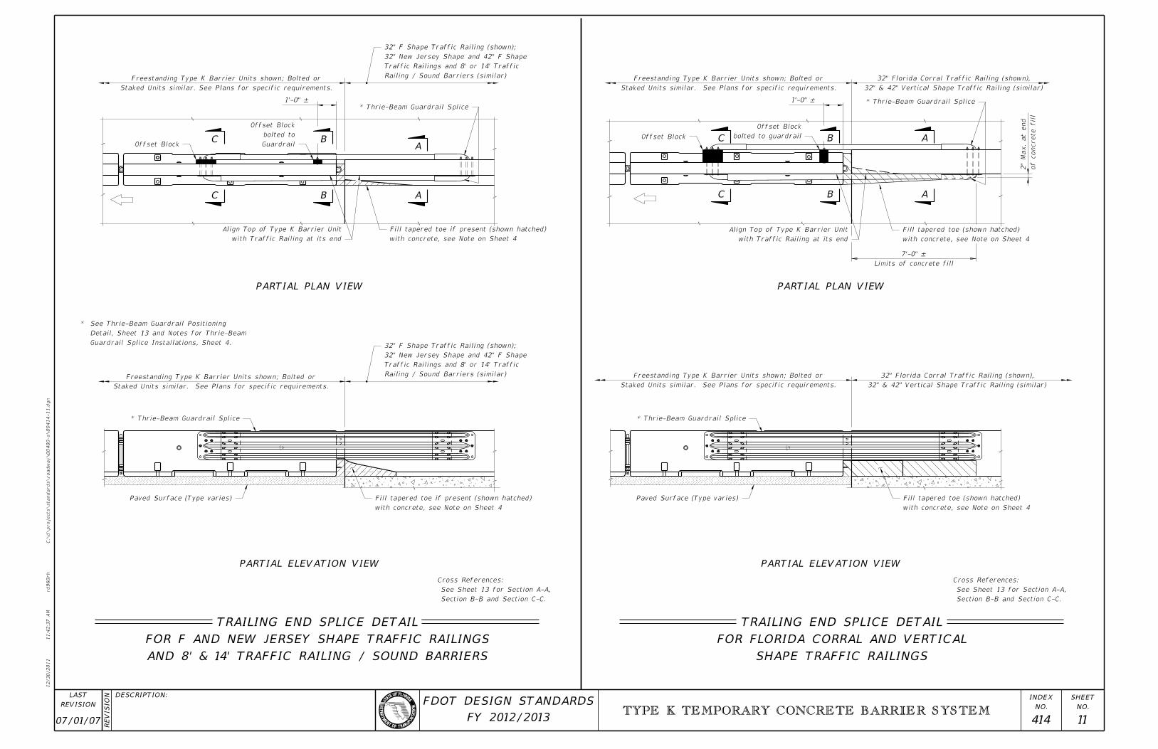
SHAPE TRAFFIC RAILINGS
FOR FLORIDA CORRAL AND VERTICAL
TRAILING END SPLICE DETAIL
AND 8’ & 14’ TRAFFIC RAILING / SOUND BARRIERS
FOR F AND NEW JERSEY SHAPE TRAFFIC RAILINGS
TRAILING END SPLICE DETAIL
Staked Units similar. See Plans for specific requirements.
Freestanding Type K Barrier Units shown; Bolted or
Staked Units similar. See Plans for specific requirements.
Freestanding Type K Barrier Units shown; Bolted or
Staked Units similar. See Plans for specific requirements.
Freestanding Type K Barrier Units shown; Bolted or
Staked Units similar. See Plans for specific requirements.
Freestanding Type K Barrier Units shown; Bolted or
32" & 42" Vertical Shape Traffic Railing (similar)
32" Florida Corral Traffic Railing (shown),
32" & 42" Vertical Shape Traffic Railing (similar)
32" Florida Corral Traffic Railing (shown),
of concrete fill
2"
Max. at end
Section B-B and Section C-C.
See Sheet 13 for Section A-A,
Cross References:
Section B-B and Section C-C.
See Sheet 13 for Section A-A,
Cross References:
Offset Block Guardrail
bolted to
Offset Block
with Traffic Railing at its end
Align Top of Type K Barrier Unit
with concrete, see Note on Sheet 4
Fill tapered toe if present (shown hatched)
* Thrie-Beam Guardrail Splice
Railing / Sound Barriers (similar)
Traffic Railings and 8’ or 14’ Traffic
32" New Jersey Shape and 42" F Shape
32" F Shape Traffic Railing (shown);
Railing / Sound Barriers (similar)
Traffic Railings and 8’ or 14’ Traffic
32" New Jersey Shape and 42" F Shape
32" F Shape Traffic Railing (shown);
* Thrie-Beam Guardrail Splice
Paved Surface (Type varies)
with concrete, see Note on Sheet 4
Fill tapered toe if present (shown hatched)
Offset Block bolted to guardrail
Offset Block
with Traffic Railing at its end
Align Top of Type K Barrier Unit
with concrete, see Note on Sheet 4
Fill tapered toe (shown hatched)
* Thrie-Beam Guardrail Splice
* Thrie-Beam Guardrail Splice
Paved Surface (Type varies)
with concrete, see Note on Sheet 4
Fill tapered toe (shown hatched)
PARTIAL PLAN VIEWPARTIAL PLAN VIEW
PARTIAL ELEVATION VIEW PARTIAL ELEVATION VIEW
C
C B
BA
A C
C B
B A
A
1’-0" – 1’-0" –
Limits of concrete fill
7’-0" –
Guardrail Splice Installations, Sheet 4.
Detail, Sheet 13 and Notes for Thrie-Beam
See Thrie-Beam Guardrail Positioning *

07/01/07 414 12
TYPE K TEMPORARY CONCRETE BARRIER SYSTEM
12/30/2011
11:4
2:3
7
AM
RE
VISIO
N
C:\
d\projects\standards\road
way\00400-s\00414-12.d
gn
NO.
SHEET
NO.
INDEX
rd960rh
DESCRIPTION:
REVISION
LAST
FY 2012/2013
FDOT DESIGN STANDARDS
WITH RAILING TRANSITION AND END POST
FOR 32" F AND NEW JERSEY SHAPE TRAFFIC RAILINGS
APPROACH TRANSITION SPLICE DETAIL
WITH RAILING TRANSITION AND END POST
FOR 32" F AND NEW JERSEY SHAPE TRAFFIC RAILINGS
TRAILING END SPLICE DETAIL
Down Units similar; See Plans for specific requirements
Freestanding Type K Barrier Units shown, Bolted or Staked
Down Units similar; See Plans for specific requirements
Freestanding Type K Barrier Units shown, Bolted or Staked
Traffic Railing
Transition
Railing
Bridge shown, Flat Slab Bridge similar)
Railing Transition & End Post (Beam or Girder
32" F or New Jersey Shape Traffic Railing,
Bridge shown, Flat Slab Bridge similar)
Railing Transition & End Post (Beam or Girder
32" F or New Jersey Shape Traffic Railing,
Offset Block bolted to Guardrail
Offset Block
(approximate location)
Begin or End Approach Slab
with Traffic Railing at its end
Align Top of Type K Barrier Unit
with concrete, see Note on Sheet 4
Fill tapered toe if present (shown hatched)
Guardrail Splice
* Thrie-Beam
* Thrie-Beam Guardrail Splice
with concrete, see Note on Sheet 4
Fill tapered toe if present (shown hatched)Approach Slab
(approximate location)
Begin or End Approach Slab
(type varies)
Paved Surface
shown, Beam or Girder Bridge similar)
Railing Transition & End Post (Flat Slab Bridge
32" F or New Jersey Shape Traffic Railing,
* Thrie-Beam Guardrail Splice Offset Block bolted to Guardrail
Offset Block Offset Block
with Traffic Railing at its end
Align Top of Type K Barrier Unit
Anchor Bolts or Stakes
* Thrie-Beam Guardrail Splice
Begin or End Bridge see Partial Plan View for locations
Anchor Bolts (shown) or Stakes;
Paved Surface similar
Approach Slab shown,
shown, Beam or Girder Bridge similar)
Railing Transition & End Post (Flat Slab Bridge
32" F or New Jersey Shape Traffic Railing,
Transition
RailingTraffic Railing
PARTIAL PLAN VIEW PARTIAL PLAN VIEW
PARTIAL ELEVATION VIEW PARTIAL ELEVATION VIEW
C
C B
B D
D
E
E B
B
C
C
Section C-C and Section E-E.
See Sheet 13 for Section B-B,
Cross References:
Section C-C and Section D-D.
See Sheet 13 for Section B-B,
Cross References:
1’-0" –1’-0" –
Guardrail Splice Installations, Sheet 4.
Detail, Sheet 13 and Notes for Thrie-Beam
See Thrie-Beam Guardrail Positioning *
Bolted or Staked Down Type K Barrier Units
Bolted or Staked Down Type K Barrier Units
End Post End Post

07/01/07 414 13
TYPE K TEMPORARY CONCRETE BARRIER SYSTEM
12/30/2011
11:4
2:3
8
AM
RE
VISIO
N
C:\
d\projects\standards\road
way\00400-s\00414-13.d
gn
NO.
SHEET
NO.
INDEX
rd960rh
DESCRIPTION:
REVISION
LAST
FY 2012/2013
FDOT DESIGN STANDARDS
Median Concrete Barrier Wall (similar)
32" F Shape Median Traffic Railing (shown),
SECTION A-A
Railing / Sound Barriers (similar)
42" Traffic Railing and 8’ & 14’ Traffic
32" F Shape Traffic Railing (shown),
SECTION A-A
Railing & other Narrow Traffic Railings (similar)
Wall (shown), 32" New Jersey Shape Traffic
32" New Jersey Shape Concrete Barrier
SECTION A-A
Traffic Railing (similar)
Railing (shown), Florida Corral
32" & 42" Vertical Shape Traffic
SECTION A-A
Median Concrete Barrier Wall
Median Traffic Railing or
Adjacent to 32" F or New Jersey Shape
SECTION C-C
Railing, Railing Transition & End Post
32" F or New Jersey Shape Traffic
SECTION D-D
Railing (similar)
(shown), 32" F Shape Traffic
32" New Jersey Shape Traffic Railing
SECTION E-E
can not be obtained
shown) when 3" Min. dimension
beyond Open Joint 1’-0" Min. (as
* Shift Thrie-Beam Guardrail Splice
in Railing
Open Joint
Min.
* 1’-0"
in Railing
Open Joint
1’-0" Max.
" Min.,85Varies 3
4’-10" Max.
Varies 2’-11" Min.,
Thrie-Beam Guardrail Splice
Traffic Railing Traffic Railing
Thrie-Beam Guardrail Splice
or Filler Plate
Offset Block
Thrie-Beam Guardrail Splice
Traffic Railing
Offset Block
Thrie-Beam Guardrail Splice
on Trailing Ends only
hatched) with concrete
Fill tapered toe (shown
or Filler Plate
Offset Block
Railing
Traffic
Thrie-Beam Guardrail SpliceThrie-Beam Guardrail Splice
Approach Transition
or Stake required for
Anchor Bolt (shown)
Type K Barrier Unit
" Ø Bolts85two
to Guardrail with
Offset Block bolted
Type K Barrier Unit
Approach Transition
(shown) required for
Anchor Bolt or Stake
Type K Barrier Unit
Approach Transition
(shown) required for
Anchor Bolt or Stake
Offset Block
Traffic Railing
Thrie-Beam Guardrail Splice Thrie-Beam Guardrail Splice
Riding Surface
Roadway Concrete Barrier Wall
Bridge Traffic Railing or
See Notes, Sheet 4
Thrie-Beam Guardrail Splice Type K Barrier Unit
Terminal Connector (Typ.)
Thrie-Beam Guardrail Splice
Traffic Railing
Offset Block
THRIE-BEAM GUARDRAIL POSITIONING DETAIL
Adjacent to Shoulder Traffic Railings
SECTION B-B
Adjacent to Shoulder Traffic Railings
SECTION C-C
* 3" Min.
Varies 7’-8" Min., 9’-7" Max.
1’-
9"
– 1"

07/01/07 414 14
TYPE K TEMPORARY CONCRETE BARRIER SYSTEM
12/30/2011
11:4
2:3
9
AM
RE
VISIO
N
C:\
d\projects\standards\road
way\00400-s\00414-14.d
gn
NO.
SHEET
NO.
INDEX
rd960rh
DESCRIPTION:
REVISION
LAST
FY 2012/2013
FDOT DESIGN STANDARDS
Approach Transition is required.
Clear Zone of opposing traffic,
Where Barrier is located within
* NOTE: Edge of Travel Way
Edge of Travel Way
Edge of Travel Way
Barrier Units (Typ.)
Barrier Units (Typ.)
Barrier Units (Typ.)
Hazard shielded by Bolted or Staked Units
First full Type K Barrier Unit before Drop-off or
Staked - 1’-0" Min.
" Nominal21Bolted - 1
See Sheet 6 for dimensions
Unit A or B (See QPL)
Type K-Proprietary Barrier Transition
Drop-off or Hazard
Unit A or B (See QPL)
Type K-Proprietary Barrier Transition
position of Bolts or Stakes
Dot indicates number and
Hazard shielded by Bolted or Staked Units
First full Type K Barrier Unit before Drop-off or
Staked - 1’-0" Min.
" Nominal21Bolted - 1
Drop-off or Hazard
See Sheet 6 for dimensions
Unit A or B (See QPL)
Type K-Proprietary Barrier Transition
Type K-Proprietary Barrier Transition Unit A or B (See QPL)
Drop-off or Hazard
See Sheet 6 for dimensions
~
or Staked Barrier Units *
Freestanding to Bolted
Transition Section from
Barrier Units (4 Units)
or Staked Type K
Partially / Fully Bolted
or Staked Barrier Units
Freestanding to Bolted
Transition Section from
Barrier Units (4 Units)
or Staked Type K
Partially / Fully Bolted
*
TYPE K-PROPRIETARY TEMPORARY CONCRETE BARRIER TRANSITIONS
LEGEND:
APPROACH TRANSITION FROM FREESTANDING PROPRIETARY TEMPORARY BARRIERS TO BOLTED OR STAKED DOWN TYPE K TEMPORARY CONCRETE BARRIERS
TRAILING END TRANSITION FROM BOLTED OR STAKED DOWN TYPE K TEMPORARY CONCRETE BARRIERS TO FREESTANDING PROPRIETARY TEMPORARY BARRIERS
APPROACH AND TRAILING END TRANSITIONS FROM FREESTANDING TYPE K TEMPORARY CONCRETE BARRIERS TO FREESTANDING PROPRIETARY TEMPORARY BARRIERS
Freestanding Proprietary Barrier Units *Fully Bolted or Staked Type K Barrier UnitsFreestanding Proprietary Barrier Units
Fully Bolted or Staked Type K Barrier Units Freestanding Proprietary Barrier Units
Freestanding Proprietary Barrier Units Freestanding Type K Barrier Units Freestanding Proprietary Barrier Units

07/01/07 414 15
TYPE K TEMPORARY CONCRETE BARRIER SYSTEM
12/30/2011
11:4
2:4
0
AM
RE
VISIO
N
C:\
d\projects\standards\road
way\00400-s\00414-15.d
gn
NO.
SHEET
NO.
INDEX
rd960rh
DESCRIPTION:
REVISION
LAST
FY 2012/2013
FDOT DESIGN STANDARDS
Approach Transition is required.
Clear Zone of opposing traffic,
Where Barrier is located within
NOTE:
Edge of Travel Way
Edge of Travel Way
Barrier Units (Typ.)
Barrier Units (Typ.)
Barrier Units (Typ.)
First full Type K Barrier Unit before Back Filled Units
See Sheet 6 for dimensions
See Sheet 6 for dimensions
Back FillDrop-off or Hazard
Transition Unit A or B (See QPL)
Type K-Proprietary Barrier
Transition Unit A or B (See QPL)
Type K-Proprietary Barrier
position of Bolts or Stakes
Dot indicates number and
Back Fill Drop-off or Hazard
Transition Unit A or B (See QPL)
Type K-Proprietary Barrier
Type K-Proprietary Barrier Transition Unit A or B (See QPL)
Filled Barrier Units *
Freestanding to Back
Transition Section from
Barrier Units (4 Units)
or Staked Type K
Partially / Fully Bolted
*
*
*
Barrier Units (4 Units)
or Staked Type K
Partially / Fully Bolted
Filled Barrier Units
Freestanding to Back
Transition Section from
TYPE K-PROPRIETARY TEMPORARY CONCRETE BARRIER TRANSITIONS
LEGEND:
APPROACH TRANSITION FROM FREESTANDING PROPRIETARY TEMPORARY BARRIERS TO BACK FILLED TYPE K TEMPORARY CONCRETE BARRIERS
TRAILING END TRANSITION FROM BACK FILLED TYPE K TEMPORARY CONCRETE BARRIERS TO FREESTANDING PROPRIETARY BARRIERS
MEDIAN APPROACH AND TRAILING END TRANSITIONS FROM FREESTANDING TYPE K TEMPORARY CONCRETE BARRIERS TO FREESTANDING PROPRIETARY TEMPORARY BARRIERS
Freestanding Proprietary Barrier Units *Back Filled Type K Barrier UnitsFreestanding Proprietary Barrier Units
Back Filled Type K Barrier Units Freestanding Proprietary Barrier Units
Freestanding Proprietary Barrier Units Freestanding Type K Barrier Units Freestanding Proprietary Barrier Units