Type JCK Class 9050 Catalog 2013
11
Catalog 2013 Electronic Timing Relays Type JCK Class 9050
Transcript of Type JCK Class 9050 Catalog 2013

Catalog
2013
Electronic Timing Relays Type JCK Class 9050

˚ Application, General Information. . . . . . . . . . . . . . . . . . . . . . . . . . . . . . . . . . . . . . . 4
˚ Selection. . . . . . . . . . . . . . . . . . . . . . . . . . . . . . . . . . . . . . . . . . . . . . . . . . . . . . . . . 6
˚ Specifi cations . . . . . . . . . . . . . . . . . . . . . . . . . . . . . . . . . . . . . . . . . . . . . . . . . . . . . 8
˚ Dimensions, Wiring Diagrams. . . . . . . . . . . . . . . . . . . . . . . . . . . . . . . . . . . . . . . . . 9
˚ Accessories . . . . . . . . . . . . . . . . . . . . . . . . . . . . . . . . . . . . . . . . . . . . . . . . . . . . . 10
Contents Type JCK Electronic Timing Relays
3

Application,General Information
Type JCK Electronic Timing Relays
Timing FunctionsClass 9050 Type JCK1•/
JCK60JCK2• JCK3• JCK4• JCK5• JCK70
TimingFunctions
On Delay
Off Delay
Off Delay Power Trigger
Interval
One Shot
One Shot Power Trigger
Repeat Cycle–Off
Repeat Cycle–On
On/Off Delay
One Shot Falling EdgeWatchdog
Trigger On Delay
Number of Pins 8 11 8 11 8 11
9050JCK Electronic Timing Functions
Function Description Timing DiagramOn Delay When the input voltage is applied, the time delay begins. Relay contacts change
state after time delay is complete. When the input voltage is removed, contacts return to their shelf state. The trigger switch is not used in this function.
Interval When the input voltage is applied, the relay contacts change state immediately and the timing cycle begins. When the time delay is complete, or when the input voltage is removed, contacts return to shelf state. The trigger switch is not used in this function.
Off Delay Switch and Power Trigger
Input voltage must be applied continuously. When the trigger switch closes, the relay contacts change state. When the trigger switch opens, the time delay begins. When the delay is complete, the contacts return to their shelf state. If the trigger switch closes before the time delay is complete, then timing is reset. When the trigger switch opens, the delay begins again, and the relay contacts remain in their energized state. If the input voltage is removed, the relay contacts return to their shelf state.
One Shot Switch and Power Trigger
Input voltage must be applied continuously. When the trigger switch closes, the relay contacts change state and the pre-set delay begins. During time-out, the trigger signal is ignored. If the input voltage is removed, the relay contacts return to their shelf state.
ON
OFF
ON
OFFDELAY
InputVoltage
Relay Contacts
DELAY
ON
OFF
ON
OFF
Input Voltage
RelayContacts
ON
OFF
CLOSED
OPEN
ON
OFF
InputVoltage
TriggerSwitch
RelayContacts
DELAY DELAY DELAY
TriggerSwitch
CLOSED
OPEN
ON
OFF
InputVoltage
ON
OFF
RelayContacts
DELAYDELAY
4
9050JCK Electronic Timing Functions
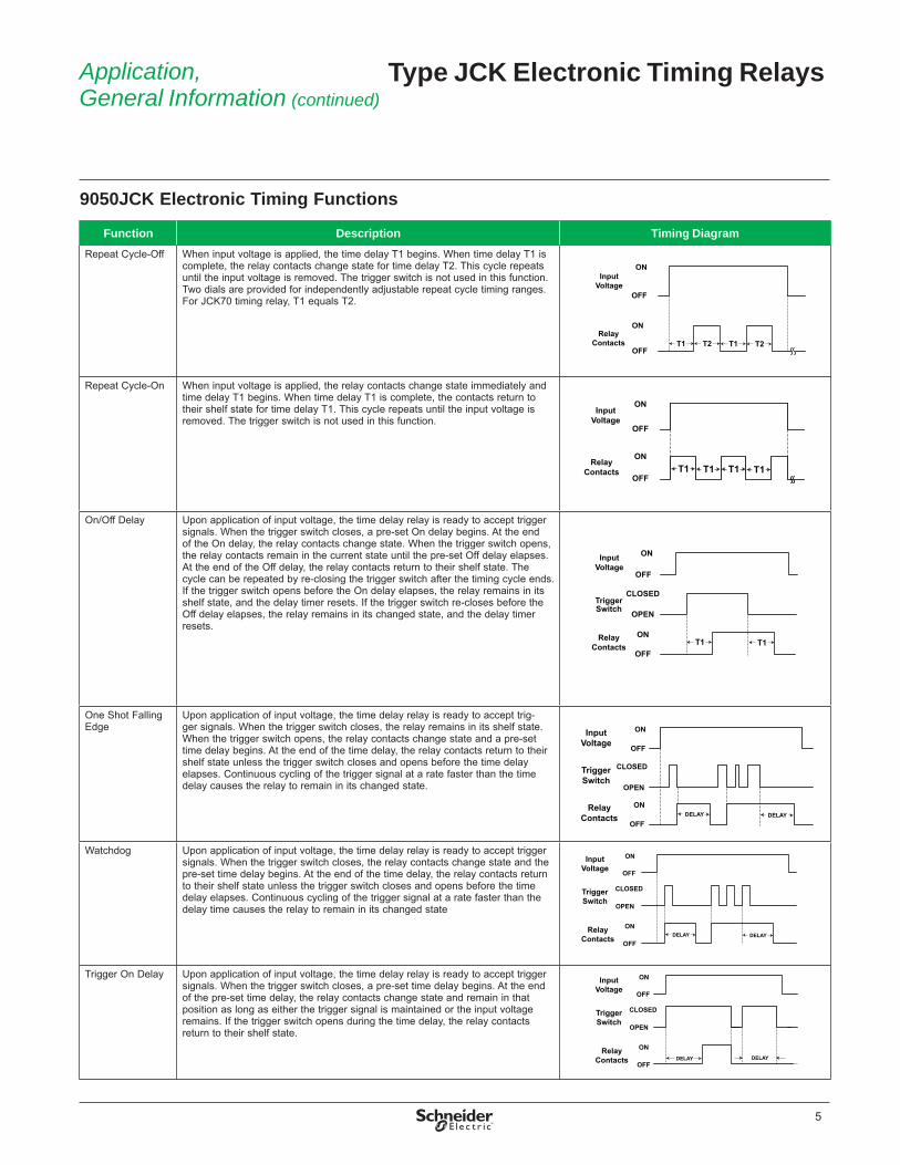
Function Description Timing DiagramRepeat Cycle-Off When input voltage is applied, the time delay T1 begins. When time delay T1 is
complete, the relay contacts change state for time delay T2. This cycle repeats until the input voltage is removed. The trigger switch is not used in this function. Two dials are provided for independently adjust able repeat cycle timing ranges. For JCK70 tim ing relay, T1 equals T2.
Repeat Cycle-On When input voltage is applied, the relay contacts change state immediately and time delay T1 begins. When time delay T1 is complete, the contacts return to their shelf state for time delay T1. This cycle repeats until the input voltage is removed. The trigger switch is not used in this function.
On/Off Delay Upon application of input voltage, the time delay relay is ready to accept trigger signals. When the trigger switch closes, a pre-set On delay begins. At the end of the On delay, the relay contacts change state. When the trigger switch opens, the relay contacts remain in the current state until the pre-set Off delay elapses. At the end of the Off delay, the relay contacts return to their shelf state. The cycle can be repeated by re-closing the trigger switch after the timing cycle ends. If the trigger switch opens before the On delay elapses, the relay remains in its shelf state, and the delay timer resets. If the trigger switch re-closes before the Off delay elapses, the relay remains in its changed state, and the delay timer resets.
One Shot Falling Edge
Upon application of input voltage, the time delay relay is ready to accept trig-ger signals. When the trigger switch closes, the relay remains in its shelf state. When the trigger switch opens, the relay contacts change state and a pre-set time delay begins. At the end of the time delay, the relay contacts return to their shelf state unless the trigger switch closes and opens before the time delay elapses. Continuous cycling of the trigger signal at a rate faster than the time delay causes the relay to remain in its changed state.
Watchdog Upon application of input voltage, the time delay relay is ready to accept trigger signals. When the trigger switch closes, the relay contacts change state and the pre-set time delay begins. At the end of the time delay, the relay contacts return to their shelf state unless the trigger switch closes and opens before the time delay elapses. Continuous cycling of the trigger signal at a rate faster than the delay time causes the relay to remain in its changed state
Trigger On Delay Upon application of input voltage, the time delay relay is ready to accept trigger signals. When the trigger switch closes, a pre-set time delay begins. At the end of the pre-set time delay, the relay contacts change state and remain in that position as long as either the trigger signal is maintained or the input voltage remains. If the trigger switch opens during the time delay, the relay contacts return to their shelf state.
InputVoltage
ON
OFF
ON
OFF
RelayContacts T2T1 T1 T2
ON
OFF
ON
OFF
InputVoltage
RelayContacts T1 T1 T1 T1
ON
OFF
ON
OFF
TriggerSwitch
CLOSED
OPEN
InputVoltage
RelayContacts T1 T1
DELAY DELAY
InputVoltage
RelayContacts
TriggerSwitch
ON
OFF
CLOSED
OPEN
ON
OFF
InputVoltage
RelayContacts
TriggerSwitch
ON
OFF
CLOSED
OPEN
ON
OFFDELAY DELAY
InputVoltage
RelayContacts
TriggerSwitch
ON
OFF
CLOSED
OPEN
ON
OFFDELAY DELAY
Application,General Information (continued)
Type JCK Electronic Timing Relays
5
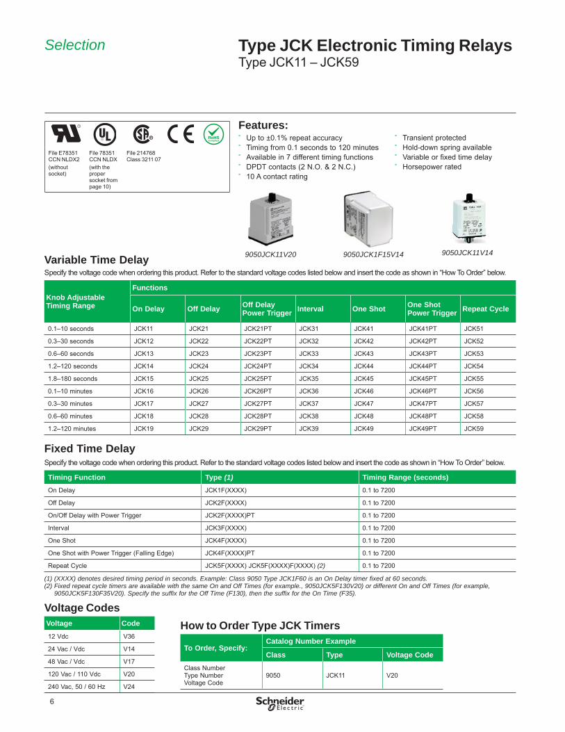
Variable Time DelaySpecify the voltage code when ordering this product. Refer to the standard voltage codes listed below and insert the code as shown in “How To Order” below.
Knob Adjustable Timing Range
Functions
On Delay Off Delay Off DelayPower Trigger Interval One Shot One Shot
Power Trigger Repeat Cycle
0.1–10 seconds JCK11 JCK21 JCK21PT JCK31 JCK41 JCK41PT JCK51
0.3–30 seconds JCK12 JCK22 JCK22PT JCK32 JCK42 JCK42PT JCK52
0.6–60 seconds JCK13 JCK23 JCK23PT JCK33 JCK43 JCK43PT JCK53
1.2–120 seconds JCK14 JCK24 JCK24PT JCK34 JCK44 JCK44PT JCK54
1.8–180 seconds JCK15 JCK25 JCK25PT JCK35 JCK45 JCK45PT JCK55
0.1–10 minutes JCK16 JCK26 JCK26PT JCK36 JCK46 JCK46PT JCK56
0.3–30 minutes JCK17 JCK27 JCK27PT JCK37 JCK47 JCK47PT JCK57
0.6–60 minutes JCK18 JCK28 JCK28PT JCK38 JCK48 JCK48PT JCK58
1.2–120 minutes JCK19 JCK29 JCK29PT JCK39 JCK49 JCK49PT JCK59
Fixed Time DelaySpecify the voltage code when ordering this product. Refer to the standard voltage codes listed below and insert the code as shown in “How To Order” below.
Timing Function Type (1) Timing Range (seconds)On Delay JCK1F(XXXX) 0.1 to 7200
Off Delay JCK2F(XXXX) 0.1 to 7200
On/Off Delay with Power Trigger JCK2F(XXXX)PT 0.1 to 7200
Interval JCK3F(XXXX) 0.1 to 7200
One Shot JCK4F(XXXX) 0.1 to 7200
One Shot with Power Trigger (Falling Edge) JCK4F(XXXX)PT 0.1 to 7200
Repeat Cycle JCK5F(XXXX) JCK5F(XXXX)F(XXXX) (2) 0.1 to 7200
(1) (XXXX) denotes desired timing period in seconds. Example: Class 9050 Type JCK1F60 is an On Delay timer fixed at 60 seconds.(2) Fixed repeat cycle timers are available with the same On and Off Times (for example., 9050JCK5F130V20) or different On and Off Times (for example,
9050JCK5F130F35V20). Specify the suffix for the Off Time (F130), then the suffix for the On Time (F35).
Voltage CodesVoltage Code12 Vdc V36
24 Vac / Vdc V14
48 Vac / Vdc V17
120 Vac / 110 Vdc V20
240 Vac, 50 / 60 Hz V24
Selection Type JCK Electronic Timing RelaysType JCK11 – JCK59
Features: ˚ Up to ±0.1% repeat accuracy ˚ Timing from 0.1 seconds to 120 minutes ˚ Available in 7 different timing functions ˚ DPDT contacts (2 N.O. & 2 N.C.) ˚ 10 A contact rating
˚ Transient protected ˚ Hold-down spring available ˚ Variable or fixed time delay ˚ Horsepower rated
9050JCK11V20 9050JCK1F15V14 9050JCK11V14
How to Order Type JCK Timers
To Order, Specify:Catalog Number Example
Class Type Voltage CodeClass NumberType NumberVoltage Code
9050 JCK11 V20
File E78351CCN NLDX2(without socket)
File 78351CCN NLDX(with the proper socket from page 10 )
File 214768Class 3211 07
6

Selection (continued) Type JCK Electronic Timing RelaysType JCK60 – JCK70
Programmable TimersClass 9050 Type JCK programmable timers are microprocessor controlled to provide flexibility with accurate timing. The Type JCK60 On Delay timer has seven programmable timing ranges. The Type JCK70 multifunction timer has 10 timing functions and seven programmable timing ranges. To program the timers, remove power and select the timing range and timing functions. Settings of less than 0.05 seconds are not recommended due to the response time of the electromechanical outputs.
Type JCK60 (On Delay)This On Delay timer uses a push-button thumbwheel to select the timing range, and uses three push-button thumbwheels to select the time value.
Timing Function Timing Ranges Type
On Delay
0.01 s0.1 sS0.1 mM0.1 hH
0.05–9.99 seconds0.1–99.9 seconds1–999 seconds0.1–99.9 minutes1–999 minutes0.1–99.9 hours1–999 hours
JCK60 (1)
(1) The voltage code must be specified to order this product. Refer to standard voltage codes listed below and insert the code as shown in “How To Order” below.
Type JCK70 (Multifunction)One 10-position push button thumbwheel is used to select the function. Three 10-position push button thumbwheels are used to select the time value. One 7-position push button thumbwheel is used to select the timing range.
Timing Functions Timing Ranges Type
On DelayIntervalOff DelayOne ShotRepeat Cycle–Off (1) Repeat Cycle–On (1)On/Off Delay1 Shot Falling EdgeWatchdogTrig. On Delay
0.01 s0.1 sS0.1 mM0.1 hH
0.05–9.99 seconds0.1–99.9 seconds1–999 seconds0.1–99.9 minutes1–999 minutes0.1–99.9 hours1–999 hours
JCK70 (2)
(1) The Repeat Cycle function uses the same On and Off times.(2) Specify the voltage code when ordering this product. Refer to the standard voltage codes listed below and insert as shown in How To Order.Note: Turn off power to the 9050JCK70 before changing the timing function.
Voltage CodesVoltage Code12 Vdc V36
24 Vac / Vdc V14
48 Vac / Vdc V17
120 Vac / 110 Vdc V20
Features: ˚ Up to ±0.1% repeat accuracy ˚ Timing from 0.05 seconds to 999 hours ˚ Available in up to 10 timing functions ˚ DPDT contacts (2 N.O. & 2 N.C.) ˚ 10 A contact rating
˚ Transient protected ˚ Hold-down spring available ˚ Wide timing range ˚ Horsepower rated
File E78351CCN NLDX2(without socket)
File 78351CCN NLDX(with the proper socket from page 10 )
File 214768Class 3211 07
How to Order Type JCK Timers
To Order, Specify:Catalog Number Example
Class Type Voltage CodeClass NumberType NumberVoltage Code
9050 JCK60 V24
7

Operating Specifications Voltage range AC operation +10%, -15% of nominal @ 50/60 Hz
DC operation +10%, -15% of nominalRepeat accuracy
For constant voltage and temperature 9050JCK11–59 ±0.1%, ±0.04 s, whichever is greater9050JCK60–70 ±0.1% of set time or ± 0.02 ms, whichever is greater
For variable voltage and temperature, within specs
9050JCK11–59 ±10%9050JCK60–70 ±0.1% of set time or 0.02 s, whichever is greater
Reset time All functions 100 msTemperature range
Operating (with the proper derating, see curve on page 9 )
12–120 Vac/Vdc –18 to +150 °F (–28 to +65 °C)240 Vac –18 to +122 °F (–28 to +50 °C)
Storage –67 to +185 °F (–55 to +85 °C)IEC 60664-1 Degree of pollution 2
Overvoltage category IIIContact material Silver nickelMounting position indifferentBurden 9050JCK11–59, 1, 2–120 Vac/Vdc 2.0 VA
9050JCK11–59, 240 Vac 3.0 VA9050JCK60–70, 12–120 Vac/Vdc 3.0 VA9050JCK60–70, 240 Vac 3.2 VA
Relative humidity 15% to 85%, per IEC 60068-2-3Insulation test voltage 9050JCK11–59
9050JCK60–702,000 Vac1,500 Vac between coil and contacts1,000 Vac between open contacts1,500 Vac between contacts of different circuitry
Transient protection 13 J, 10x 1000 μsVibration 10–55 Hz, 3 g max., 0.5 mm total displacement (+0.25 mm)Shock 30 g, 11 ms duration, half sine waveEndurance (1) Mechanical (no load, 18,000 operations/hr max.) 10 million operations
Electrical (full rated load, 1,800 operations/hr max., operating temperature –18 to 104 °F [–28 to 40 °C]).
100,000 operations
Degree of protection (IEC 60529) IP20Max. switching frequency 1800 cycles per hourCompliance UL Component Recognized File E78351 CCN NLDX2 (without socket)
UL Listed File E78351 CCN NLDX (with the proper socket from page 10 )CSA File 214768 Class 3211 07CE EN60947-4-1, EN60947-5-1, EN61812-1RoHS As of Series E for JCK1-59
As of Series D for JCK60 and JCK70Fuse 10 A, Class CC (e.g., Bussmann KTK-R 10)
(1) The product life expressed on this page is based on average and normal operating conditions. Actual life will vary with conditions. The above statements are not intended to, nor shall they, create any expressed or implied warranties as to product operation or life. For more information on the listed warranty offered on this product, refer to the Terms and Conditions of sale found in the Digest.
Electromagnetic Compatibility (EMC) RatingsTest IEC LevelElectrostatic discharge 61000-4-2 3 (6 kV, 8 kV)Radiated, radio-frequency, electromagnetic field 61000-4-3 3 (10 V/m)Electrical fast transient/burst 61000-4-4 3 (2 kV, 1 kV) (1)Surge 61000-4-5 3 (2 kV, 1 kV) (1)
Conducted disturbances, induced by radio-frequency fields 61000-4-6 3 (10 V/m)Radiated emissions CISPR 22Conducted emissions CISPR 22
(1) Supply port, output port, and control port
LED Indicators (1)
LED StateSteady (On) Power present
Flashing Device is timing
(1) The LED is not an indicator of the output state of the timing relay.
Specifi cations Type JCK Electronic Timing Relays
8

Dimensions,Wiring Diagrams
Type JCK Electronic Timing Relays
AC Maximum Contact RatingsAC Voltage 120 / 240 Vac (N.C.) 120 / 240 Vac (N.O.)
Horsepower 1/3 1/2
AC Amperes
Resistive 75% P.F. Make, Break, and Continuous 10 10
Inductive 35% P.F. Continuous 10 10
Break 3 1.5
Make 30 15
NOTES:• Use the same voltage for the
power trigger and control power. Do not use terminal 6 with power trigger devices.
• For timers that use trigger switches, the maximum distance for the trigger switch is 50 ft. from the timer.
Rep
eat
Cyc
le T
imer
s
2.4061
MIN. MAX. MIN. MAX.
ONENERGIZADO
SOUS TENSION
OFFDESENERGIZADOHORS TENSION 1.71
43
MIN. MAX.
2.4061
1.7143
All
Oth
ers
2.79713.39
86
4.10104
Dimensions of Type JCK11 – JCK59 Dimensions of Type JCK60 and JCK70
2.38 60
2.88 73
1.75 44
3.55 91
The knob shown is for variable time versions only.
Wiring Diagrams
Dimensions — inches mm
Contact Derating Curve
0 A
5 A
10 A
10 ˚C 40 ˚C 55 ˚C
Consult the factory
DC Maximum Contact Ratings
DC Volts 30
DC Amperes
Resistive Make, Break, and Continuous 10
Inductive Make 3
Break 3AC15/B300 (NO/NC), DC13/R300 (NO)Recommended minimum load current is 100 mA @ 12 Vdc.
4 8
111
32
9
65 7
10
+ –
Customer Supplied Trigger Switch(Hard Contact Only)
L1 L2
4 5
6
7
81
2
3
+ –L1 L2
Power Trigger
++ –L1 L2
4 8
111
32
9
65 7
10
+ –
Customer suppliedswitch for
power trigger
L1 L2
111098
7654321
Control Power
Customer SuppliedTrigger Switch
(Hard Contact Only)
Type (1):JCK11 – JCK19JCK31 – JCK39JCK51 – JCK59JCK60
Type (1):JCK21PT – JCK29PTJCK41PT – JCK49PT
Type (1):JCK70
Control Power Control Power Control Power
Type (1) (2):JCK21 – JCK29JCK41 – JCK49
PIN 10Control Power
PIN 2
5 6(1) Do not apply DC voltage to the 240 Vac timers (voltage code V24).(2) There is no internal jumper between pins 6 and 7.
9

Snapmount Sockets-Screw TerminalFor Use with Class 9050 Type Description Socket Rating Type Order Qty.
JCK11–19JCK31–39JCK51–59JCK60JCK1FJCK3FJCK5F
8–Pin TubularSingle Tier
UL 10 A @ 600 V, 15 A @ 300 V 8501NR518501NR51B
110 (bulk package)CSA 10 A @ 300 V
8–Pin TubularDouble Tier
UL 5 A @ 600 V, 16 A @ 300 V8501NR528501NR52B
110 (bulk package)CSA 10 A @ 300 V
JCK21–29JCK41–49JCK70JCK2FJCK4F
11–Pin TubularSingle Tier
UL 5 A @ 600 V, 15 A @ 300 V 8501NR618501NR61B
110 (bulk package)CSA 10 A @ 300 V (20 A max. load)
11–Pin TubularThree Tier
UL 5 A @ 600 V, 16 A @ 300 V 8501NR62 (1) 8501NR62B
110 (bulk package)CSA 10 A @ 300 V (20 A max. load)
(1) The 8501NR62 socket is approximately the same width as the base of the JCK timer. Use the wider NR61 where space permits for ease of wiring.
Input CompatabilityThe Type JCK timer is not compatible with 2-wire AC input sensors. A hard contact relay (for instance, a general purpose relay) must be interposed. Class 8501 Type NR sockets are designed for use with plug-in Class 9050 Type JCK timers. All sockets have pressure clamps that accept one or two #12–22 AWG wires. The recommended tightening torque for all terminals is 7–8 lb-in.
˚ 35 mm DIN 3 track mounting or direct panel mounting
˚ Tubular sockets available in easy-to-wire single tier or space-saving multi-tier versions
˚ All sockets are stocked
Selection Type JCK Electronic Timing RelaysAccessories
Class 8501 Hold-Down Spring For Use on Class 9050 Type JCK Timers Class TypeHold-down spring to hold the timer in its socket during heavy vibration. (See the photo on page 6 of the 9050JCK timer with the 8501NH7 hold-down spring attached.) 8501 NH7
Note: For DIN3 mounting track and end clamps, refer to the IEC type terminal block section in Catalog 9080CT9901.
Conformity to Standards (Sockets Only):
File E66924 CCN SWIV2
File 211268Class 3211 07
8501NR62
8501NR52
8501NR61
8501NR51
8501NH7
10

Dimensions,Wiring Diagrams
Type JCK Electronic Timing RelaysAccessories
Socket Dimensions and Wiring Diagrams — inches mm
32111109
8 4567
TerminalLocation
Top ViewNR61 8501NR618501NR51
3456
LocationTerminal
NR51ViewTop
21870.7720
0.9725
Terminal screws M3 .5 x .6
2.1454
2.0351
1.3033
1.6041
0.174
1.0126
1.07(27)
0.7720
0.9725
Terminal screws 6-32 x 5/16"
dia.0.174
2.0652
2.3359
0.9624
1.3033
2.1655
2.0452
1.0928
1.4236
3.0678
2.8673
0.8822
0.7118
1.1128
0.144
1.5740
2.0452
TerminalscrewsM3.5 x 7
5 1 4
6 8 33
7 2
8 7 5 4
3
11 6
9
210
3.2282
3.0277
1.8848
0.7619
0.3810
0.7118
1.4437
0.6216
1.0326
1.3234
1.5038
1.7946
TerminalLocationTerminal
8501NR52 8501NR62
0.144
Terminal screwsM3.5 x 7
NR52ViewTop
NR62ViewTop
Dimensions: Inchesmm
11

© 2013 Schneider Electric. All Rights ReservedSchneider Electric and Square D are trademarks owned by Schneider Electric Industries SAS or its affi liated companies. All other trademarks are the property of their respective owners.
9050CT9601R06/13 Replaces 9050CT9601R03/09 dated 11/2011
http://www.schneider-electric.com/
6/2013
Schneider Electric USA, Inc.1415 S. Roselle Road Palatine, IL 60067 USA
Tel: 888-778-2733www.schneider-electric.us