Type code for standard program -...
27
Type code for standard program A10V O / 31 – V 01 02 03 04 05 06 07 08 09 10 11 12 13 Version 18 28 45 71 100 140 01 Standard version (without symbol) l l l l l l HFA, HFB, HFC hydraulic fluid (except for Skydrol) – l l l l l E High-speed version – – l l l l H Axial piston unit 02 Swashplate design, variable, nominal pressure 280 bar, maximum pressure 350 bar A10VS Operation mode 03 Pump, open circuit O Size (NG) 04 Geometric displacement, see table of values on pages 6 and 7 18 28 45 71 100 140 Control device 05 Two-point control, directly operated l l l l l l DG Pressure control l l l l l l DR with flow control, hydraulic X-T open l l l l l l DFR X-T closed l l l l l l DFR1 with swivel angle control, electric – l l l l l FE1 1) pressure and swivel-angle control, electric l l l l l l DFE1 1) with pressure cut-off, remotely operated hydraulic l l l l l l DRG electrical negative characteristic 12V l l l l l l ED71 24V l l l l l l ED72 positive characteristic 12V l l l l l l ER71 2) 24V l l l l l l ER72 2) Pressure, flow and power control – l l l l l DFLR Series 06 Series 3, Index 1 31 Direction of rotation 07 Viewed on drive shaft clockwise R counter clockwise L Seals 08 FKM (fluor-caoutchouc) V = available m = on request – = not available See RE 30030 1) The following must be taken into account during project planning: 2) Excessive current levels (I > 1200 mA with 12 V or I > 600 mA with 24 V) to the ER solenoid can result in undesired increase of pressure which can lead to pump or system damage: - Use I max current limiter solenoids. - A sandwich plate pressure reducing valve can be used to protect the pump in the event of overflow.
-
Upload
duongthuan -
Category
Documents
-
view
244 -
download
0
Transcript of Type code for standard program -...

Type code for standard program
A10V O / 31 – V01 02 03 04 05 06 07 08 09 10 11 12 13
Version 18 28 45 71 100 140
01
Standard version (without symbol) l l l l l l
HFA, HFB, HFC hydraulic fluid (except for Skydrol) – l l l l l E
Highspeed version – – l l l l H
Axial piston unit02 Swashplate design, variable, nominal pressure 280 bar, maximum pressure 350 bar A10VS
Operation mode03 Pump, open circuit O
Size (NG)04 Geometric displacement, see table of values on pages 6 and 7 18 28 45 71 100 140
Control device
05
Twopoint control, directly operated l l l l l l DG
Pressure control l l l l l l DR
with flow control, hydraulic
XT open l l l l l l DFR
XT closed l l l l l l DFR1
with swivel angle control, electric – l l l l l FE11)
pressure and swivelangle control, electric l l l l l l DFE11)
with pressure cutoff, remotely operated
hydraulic l l l l l l DRG
electrical negative characteristic 12V l l l l l l ED71
24V l l l l l l ED72
positive characteristic 12V l l l l l l ER712)
24V l l l l l l ER722)
Pressure, flow and power control – l l l l l DFLR
Series06 Series 3, Index 1 31
Direction of rotation
07Viewed on drive shaft clockwise R
counter clockwise L
Seals08 FKM (fluorcaoutchouc) V
= available m = on request – = not available
See RE 300301)
The following must be taken into account during project planning: 2)
Excessive current levels (I > 1200 mA with 12 V or I > 600 mA with 24 V) to the ER solenoid can result in undesired increase of pressure which can lead to pump or system damage: Use Imax current limiter solenoids. A sandwich plate pressure reducing valve can be used to protect the pump in the event of overflow.
Type code for standard program
A10V O / 31 – V01 02 03 04 05 06 07 08 09 10 11 12 13
Drive shaft 18 28 45 71 100 140
09
Splined shaft ANSI B92.1a
standard shaft l l l l l l S
similar to shaft "S" however for higher input torque l l l l – – R
Parallel keyed shaft DIN 6885
not for through drivel l l l l l P
Mounting flange 18 28 45 71 100 140
10ISO 30192 2hole l l l l l – A
4hole – – – – – l B
Service line port 18 28 45 71 100 140
11SAE flange ports on opposite side, metric fastening thread l l l – l l 12
– – – l – – 42
Through drive 18 28 45 71 100 140
12
without through drive l l l l l l N00
Flange ISO 30191 coupling for splined shaft1)
Diameter diameter
822 (A) 5/8 in 9T 16/32DP l l l l l l K01
3/4 in 11T 16/32DP l l l l l l K52
1012 (B) 7/8 in 13T 16/32DP – l l l l l K68
1 in 15T 16/32DP – – l l l l K041272 (C) 1 1/4 in 14T 12/24DP – – – l l l K07
1 1/2 in 17T 12/24DP – – – – l l K241524 (D) 1 3/4 in 13T 8/16DP – – – – – l K17
Ø 63, metric 4hole shaft key Ø 25 – l l l l l K57Flange ISO 30192 Diameter
80, 2hole 3/4 in 11T 16/32DP l l l l l l KB2100, 2hole 7/8 in 13T 16/32DP – l l l l l KB3
1 in 15T 16/32DP – – l l l l KB4125, 2hole 1 1/4 in 14T 12/24DP – – – l l l KB5
1 1/2 in 17T 12/24DP – – – – l l KB6180, 4hole 1 3/4 in 13T 8/16DP – – – – – l KB7
Connectors for solenoids2) 18 28 45 71 100 14013 HIRSCHMANN connector – without suppressor diode l l l l l l H
Coupling for splined shaft as per ANSI B92.1a1)
Connectors for other electric components can deviate.2)
= available m = on request – = not available

Technical data, standard unitTable of values (theoretical values, without efficiencies and tolerances: values rounded)
Size NG 18 28 45 71 100 140
Geometrical displacement per revolution
Vg max cm3 18 28 45 71 100 140
Speed1)
maximum at Vg max nnom rpm 3300 3000 2600 2200 2000 1800
maximum at Vg < Vg max nmax perm rpm 3900 3600 3100 2600 2400 2100
Flow
at nnom and Vg max qv max l/min 59 84 117 156 200 252
at nE = 1500 rpm and Vg max qvE max l/min 27 42 68 107 150 210
Power at Dp = 280 bar
at nnom, Vg max Pmax kW 30 39 55 73 93 118
at nE = 1500 rpm and Vg max PE max kW 12.6 20 32 50 70 98
Torque
at Vg max and Dp = 280 bar Tmax Nm 80 125 200 316 445 623
Dp = 100 bar T Nm 30 45 72 113 159 223Rotary stiffness, drive shaft
S c Nm/rad 11087 22317 37500 71884 121142 169537
R c Nm/rad 14850 26360 41025 76545 – –
P c Nm/rad 13158 25656 41232 80627 132335 188406
Moment of inertial rotary group JTW kgm2 0.00093 0.0017 0.0033 0.0083 0.0167 0.0242
Angular acceleration, maximum2) a rad/s2 6800 5500 4000 3300 2700 2700
Filling capacity V L 0.4 0.7 1.0 1.6 2.2 3.0
Weight (without through drive) approx. m kg 12 15 21 33 45 60
The values are applicable:1)
for an absolute pressure pabs = 1 bar at suction port S within the optimum viscosity range from nopt = 16 to 36 mm2/s for mineraloil based hydraulic fluid.
The scope of application lies between the minimum necessary and the maximum permissible drive speeds. 2)
Valid for external excitation (e.g. diesel engine 2 to 8fold rotary frequency, cardan shaft 2fold rotary frequency). The limiting value is only valid for a single pump. The loading capacity of the connecting parts must be taken into account.
NoteExceeding the maximum or falling below the minimum permissible values can lead to a loss of function, a reduction in operational service life or total destruction of the axial piston unit. We recommend to check the loading through tests or calculation / simulation and comparison with the permissible values.
Determination of size
Flow qV =Vg • n • hV
[l/min]Vg = Displacement per revolution in cm3
1000 Dp = Differential pressure in bar
Torque T =Vg • Dp
[Nm]n = Speed in rpm
20 • p • hmh hV = Volumetric efficiency
Power P =2p • T • n
=qV • Dp
[kW]hmh = Mechanicalhydraulic efficiency
60000 600 • ht ht = Total efficiency(ht = hV • hmh)

Technical data, highspeed versionTable of values (theoretical values, without efficiencies and tolerances: values rounded)
Size NG 45 71 100 140
Geometrical displacement per revolution
Vg max cm3 45 71 100 140
Speed1)
maximum at Vg max nnom rpm 3000 2550 2300 2050
maximum at Vg < Vg max nmax perm rpm 3300 2800 2500 2200
Flow
at nnom and Vg max qv max l/min 135 178 230 287
Power at Dp = 280 bar
at nnom, Vg max Pmax kW 63 83 107 134
Torque
at Vg max and Dp = 280 bar Tmax Nm 200 316 445 623
Dp = 100 bar T Nm 72 113 159 223Rotary stiffness, drive shaft
S c Nm/rad 37500 71884 121142 169537
R c Nm/rad 41025 76545 – –
P c Nm/rad 41232 80627 132335 188406
Moment of inertial rotary group JTW kgm2 0.0033 0.0083 0.0167 0.0242
Angular acceleration, maximum2) a rad/s2 4000 3300 2700 2700
Filling capacity V L 1.0 1.6 2.2 3.0
Weight (without through drive) approx. m kg 21 33 45 60
The values are applicable:1)
for an absolute pressure pabs = 1 bar at suction port S within the optimum viscosity range from nopt = 16 to 36 mm2/s for mineraloil based hydraulic fluid.
The scope of application lies between the minimum necessary and the maximum permissible drive speeds. 2)
Valid for external excitation (e.g. diesel engine 2 to 8fold rotary frequency, cardan shaft 2fold rotary frequency). The limiting value is only valid for a single pump. The loading capacity of the connecting parts must be taken into account.
NoteExceeding the maximum or falling below the minimum permissible values can lead to a loss of function, a reduction in operational service life or total destruction of the axial piston unit. We recommend to check the loading through tests or calculation / simulation and comparison with the permissible values.
Sizes 45, 71, 100 and 140 are optionally available in highspeed version. External dimensions are not affected by this option.
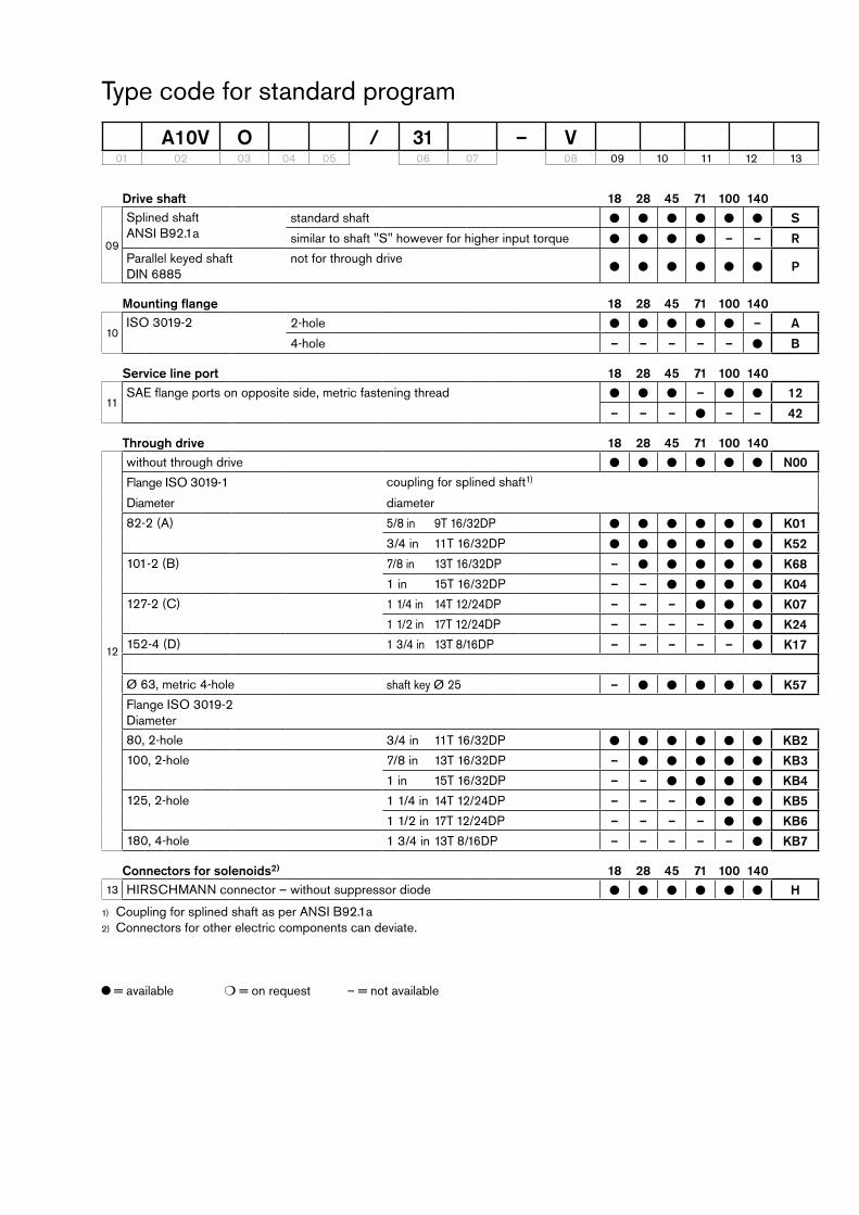
Dimensions size 18DFR, DFR1 – Pressure and flow control, hydraulic Clockwise rotation
PortsDesignation Port for Standard Size1) Maximum
pressure [bar]2)State
B Service line, fastening thread
SAE J5183) DIN 13
3/4 in M10 x 1.5; 17 deep
350 O
S Suction line, fastening thread
SAE J5183) DIN 13
1 in M10 x 1.5; 17 deep
10 O
L Case drain fluid DIN 38524) M16 x 1.5; 12 deep 2 O5)
L1 Case drain fluid DIN 38524) M16 x 1.5; 12 deep 2 X5)
X Pilot pressure DIN 38524) M14 x 1.5; 12 deep 350 O
X Pilot pressure with DGcontrol DIN ISO 2284) G 1/4 in 350 O
195
6363
W
V
145
XL
L1
108
43
Ø80
-0.0
460
6.383
11.5
52.4
26.2
S
S
Ø25
47.6
Ø20
B
B
22.2
L
126
40
152
66
11
109
max
. 110
64 69
109
45°45°
X
View W
Valve mounting for ccw rotation
View V
Flange ISO 30192
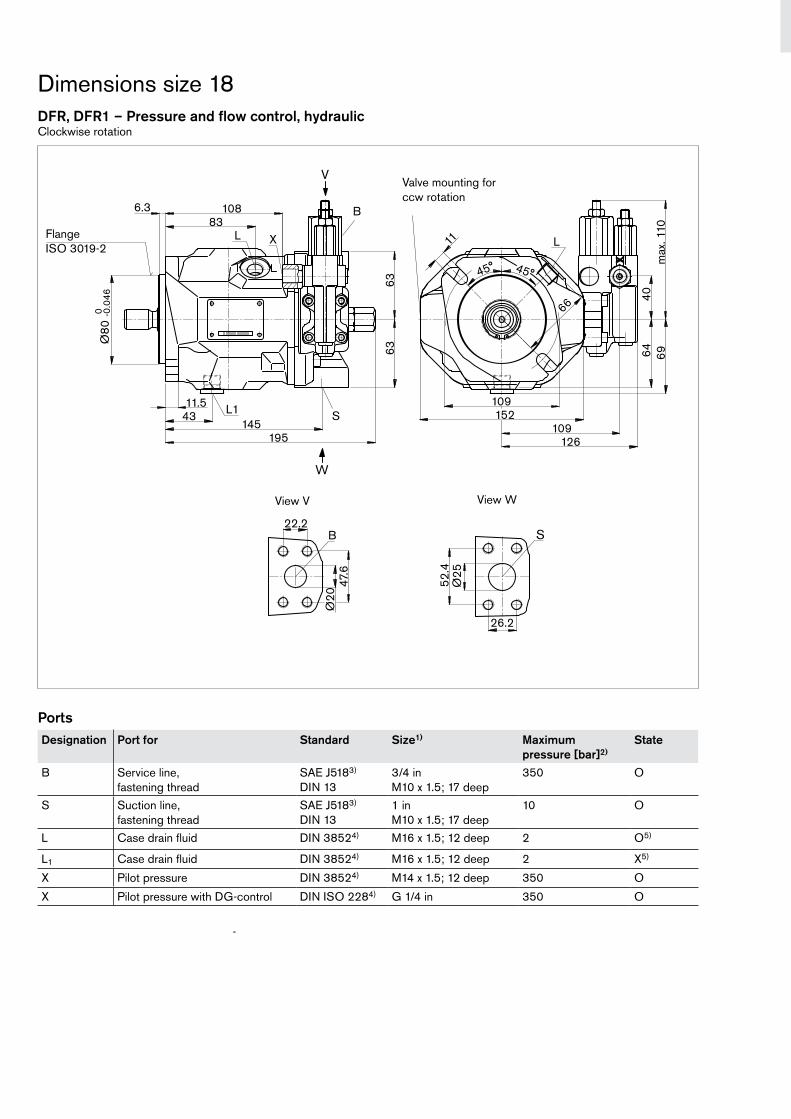
Dimensions size 18 Before finalizing your design request a certified installation drawing. Dimensions in mm.
Drive shaftS Splined shaft 3/4 in
11T 16/32DP1) (SAE J744)R Splined shaft 3/4 in
11T 16/32DP1)2) (SAE J744)P Parallel shaft key
DIN 6885, A6x6x25
ANSI B92.1a, 30° pressure angle, flat root, side fit, tolerance class 51)
Splines according to ANSI B92.1a, run out of spline is a deviation from standard2)
Thread according to ASME B1.13)
38
145
30
21
1/4-
20U
NC
-2B
3) 4
)
36
2 25
28 0
20.5
-0.1
ø18
- 0.0
03+
0.0
08
ø22
- 0.0
33 0
+ 0.3
1/4-
20U
NC
-2B
3) 4
)
14
38
21
5
Centering5) R 3.15 x 6.7 DIN 332
Usable shaft length
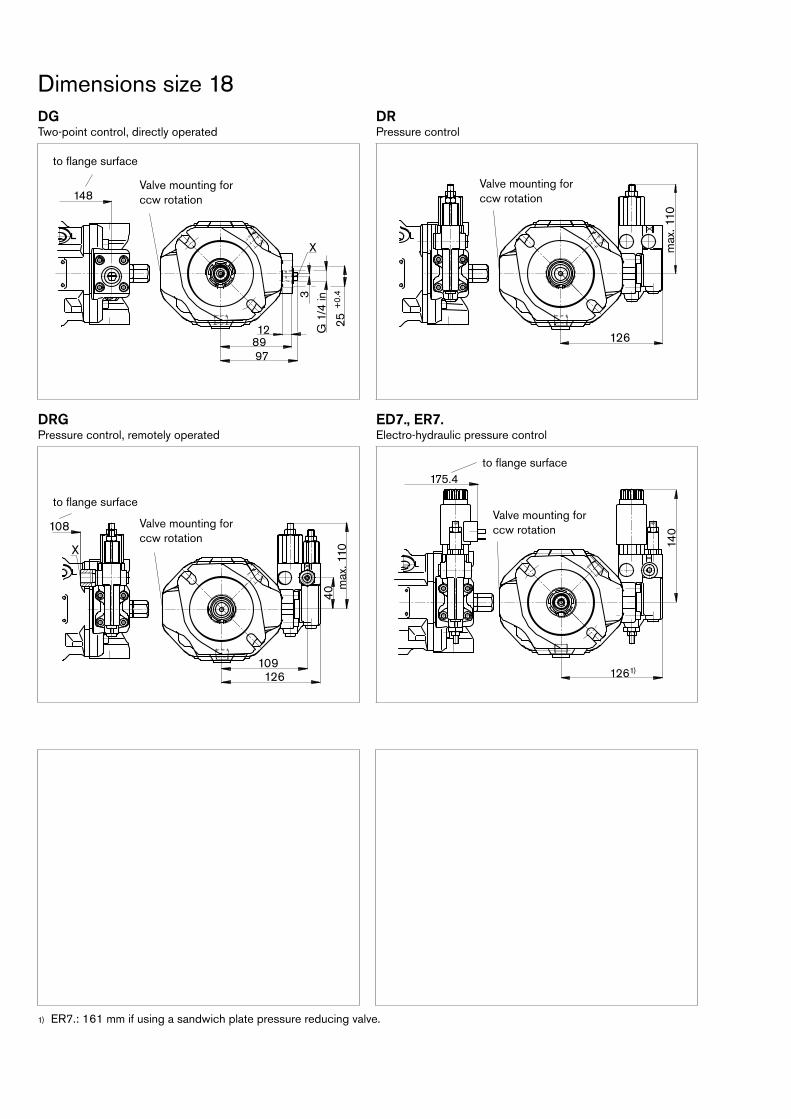
Dimensions size 18DGTwopoint control, directly operated
DRPressure control
DRGPressure control, remotely operated
ED7., ER7.Electrohydraulic pressure control
ER7.: 161 mm if using a sandwich plate pressure reducing valve.1)
3G
1/4
in
25+
0.4
8912
97
X
148
126
max
. 110
X
X
108
126
40
109
max
. 110
X
1261)14
0
X
175.4
to flange surface
to flange surface
to flange surface
Valve mounting for ccw rotation
Valve mounting for ccw rotation
Valve mounting for ccw rotation
Valve mounting for ccw rotation
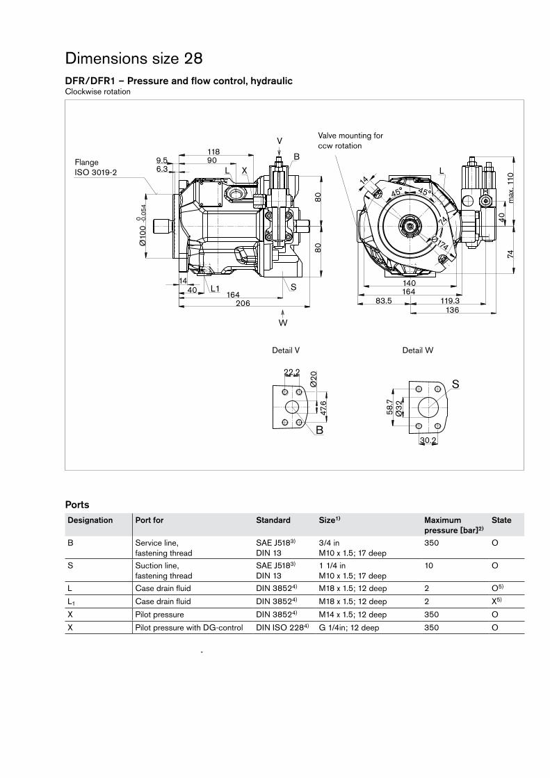
Dimensions size 28DFR/DFR1 – Pressure and flow control, hydraulic Clockwise rotation
PortsDesignation Port for Standard Size1) Maximum
pressure [bar]2)State
B Service line, fastening thread
SAE J5183) DIN 13
3/4 in M10 x 1.5; 17 deep
350 O
S Suction line, fastening thread
SAE J5183) DIN 13
1 1/4 in M10 x 1.5; 17 deep
10 O
L Case drain fluid DIN 38524) M18 x 1.5; 12 deep 2 O5)
L1 Case drain fluid DIN 38524) M18 x 1.5; 12 deep 2 X5)
X Pilot pressure DIN 38524) M14 x 1.5; 12 deep 350 O
X Pilot pressure with DGcontrol DIN ISO 2284) G 1/4in; 12 deep 350 O
X
S58
.7Ø
32
30.2B
22.2
Ø20
47.6
Ø10
0-0
.054
0
8080
206
1440
XL L
L1164
6.39.5
W
V
90118
136119.3
74
83.5
140164
max
. 110
4074
14
45°45°
Ø174
S
B
Detail V Detail W
Flange ISO 30192
Valve mounting for ccw rotation

Dimensions size 28Drive shaftS Splined shaft 7/8 in
13T 16/32DP1) (SAE J744)R Splined shaft 7/8 in
13T 16/32DP1)2) (SAE J744)P Parallel shaft key
DIN 6885, A6x6x32
ANSI B92.1a, 30° pressure angle, flat root, side fit, tolerance class 51)
Spline according to ANSI B92.1a, run out of spline is a deviation from standard.2)
Thread according to ASME B1.13)
Thread according to DIN 134)
41
165
33.1
25.1
1/4-
20U
NC
-2B
3) 5
)
1/4-
20U
NC
-2B
3) 5
)
16
41
25
5
ø22 M
64), 5
)
24.4
-0.2
46
216
36 + 0.30.0
32
-0.0
04+
0.00
9
Usable shaft length
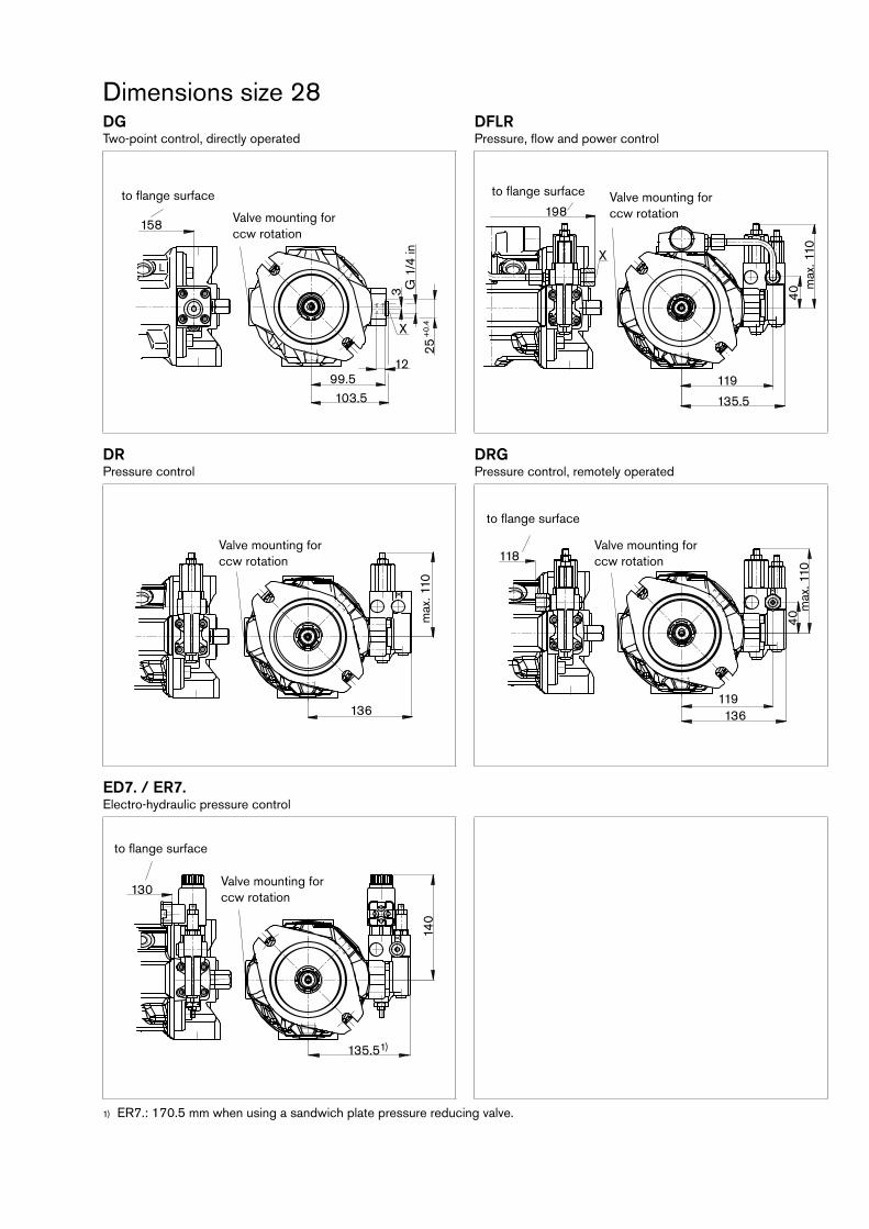
Dimensions size 28DGTwopoint control, directly operated
DFLRPressure, flow and power control
DRPressure control
DRGPressure control, remotely operated
ED7. / ER7.Electrohydraulic pressure control
ER7.: 170.5 mm when using a sandwich plate pressure reducing valve.1)
130
135.51)
X 140
L
3 G 1
/4 in
25+
0.4
99.5103.5
12
X
158
X
136
max
. 110 X
118
136119
max
. 110
4040
max
. 110
135.5
119
198
X
Valve mounting for ccw rotation
Valve mounting for ccw rotation
Valve mounting for ccw rotation
Valve mounting for ccw rotation
Valve mounting for ccw rotation
to flange surface
to flange surface
to flange surface
to flange surface
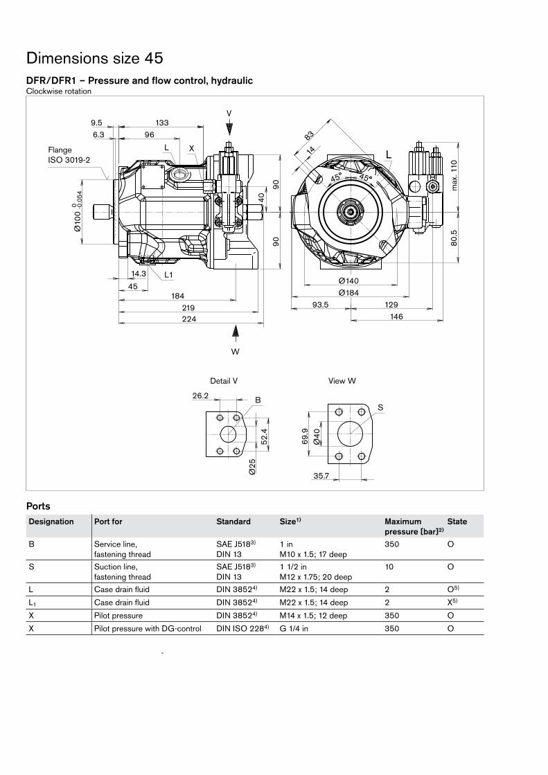
Dimensions size 45DFR/DFR1 – Pressure and flow control, hydraulic Clockwise rotation
PortsDesignation Port for Standard Size1) Maximum
pressure [bar]2)State
B Service line, fastening thread
SAE J5183) DIN 13
1 in M10 x 1.5; 17 deep
350 O
S Suction line, fastening thread
SAE J5183) DIN 13
1 1/2 in M12 x 1.75; 20 deep
10 O
L Case drain fluid DIN 38524) M22 x 1.5; 14 deep 2 O5)
L1 Case drain fluid DIN 38524) M22 x 1.5; 14 deep 2 X5)
X Pilot pressure DIN 38524) M14 x 1.5; 12 deep 350 O
X Pilot pressure with DGcontrol DIN ISO 2284) G 1/4 in 350 O
W
V
X
35.7
Ø40
69.9
SB
Ø25
52.4
26.2
129146
133
9090
max
. 110
40
Ø140
9.5
LL
X
L1
Ø10
0
-0.0
540
219224
Ø184
966.3
18445
14.3
80.5
93.5
14
83
45°45°
View WDetail V
Flange ISO 30192
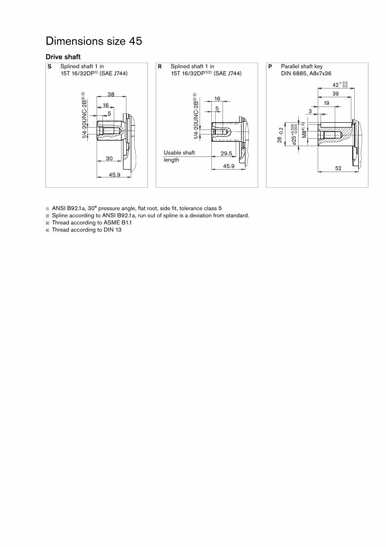
Dimensions size 45Drive shaftS Splined shaft 1 in
15T 16/32DP1) (SAE J744)R Splined shaft 1 in
15T 16/32DP1)2) (SAE J744)P Parallel shaft key
DIN 6885, A8x7x36
ANSI B92.1a, 30° pressure angle, flat root, side fit, tolerance class 51)
Spline according to ANSI B92.1a, run out of spline is a deviation from standard.2)
Thread according to ASME B1.13)
Thread according to DIN 134)
45.9
165
38
30
1/4-
20U
NC
-2B
3) 5
)
1/4-
20U
NC
-2B
3) 5
)
16
45.9
29.5
5
ø25 M
84), 5
)
28 -0
.2
52
319
42 + 0.30.0
39
-0.0
04+
0.00
9
Usable shaft length

Dimensions size 45DGTwopoint control, directly operated
DFLRPressure, flow and power control
DRPressure control
DRGPressure control, remotely operated
ED7. / ER7.Electrohydraulic pressure control
ER7.: 180.5 mm if using a sandwich plate pressure reducing valve.1)
140
145.51)
146
L XG
1/4
in25
+0.
4
173
110117
X
3
12
X
146
max
. 110
X
129146
133
max
. 110
40
X
40
129
X
112
213
146
Valve mounting for ccw rotation
Valve mounting for ccw rotation
Valve mounting for ccw rotation
Valve mounting for ccw rotation
Valve mounting for ccw rotation
to flange surface
to flange surface
to flange surface
to flange surface

Dimensions size 71DFR/DFR1 – Pressure and flow control, hydraulic Clockwise rotation
PortsDesignation Port for Standard Size1) Maximum
pressure [bar]2)State
B Service line, fastening thread
SAE J5183) DIN 13
1 in M10 x 1.5; 17 deep
350 O
S Suction line, fastening thread
SAE J5183) DIN 13
2 in M12 x 1.75; 20 deep
10 O
L Case drain fluid DIN 38524) M22 x 1.5; 14 deep 2 O5)
L1 Case drain fluid DIN 38524) M22 x 1.5; 14 deep 2 X5)
X Pilot pressure DIN 38524) M14 x 1.5; 12 deep 350 O
X Pilot pressure with DGcontrol DIN ISO 2284) G 1/4 in 350 O
L
77.8
Ø50
S
42.9
Ø2552.4
26.2
B
257
V
W
92m
ax. 1
10
143107.5160
40
5318
Ø12
5-0
.063
0
1898
180210
L1
L
104
104
1616 115
12.7
45°45°
X
217
X
Detail V Detail W
Flange ISO 30192
Valve mounting for ccw rotation

Drive shaftS Splined shaft 1 1/4 in
14T 12/24DP1) (SAE J744)R Splined shaft 1 1/4 in
14T 12/24DP1)2) (SAE J744)P Parallel shaft key
DIN 6885, A10x8x45
ANSI B92.1a, 30° pressure angle, flat root, side fit, tolerance class 51)
Spline according to ANSI B92.1a, run out of spline is a deviation from standard.2)
Thread according to ASME B1.13)
Thread according to DIN 134)
Dimensions size 71
55.4
195
47.5
39.5
5/16
-18U
NC
-2B
3) 5
)
5/16
-18U
NC
-2B
3) 5
)
19
55.4
38
5
ø32 M
104)
, 5)
35 -0
.2
60
2.522
50
47.5
+0.
018
+0.
002
Usable shaft length
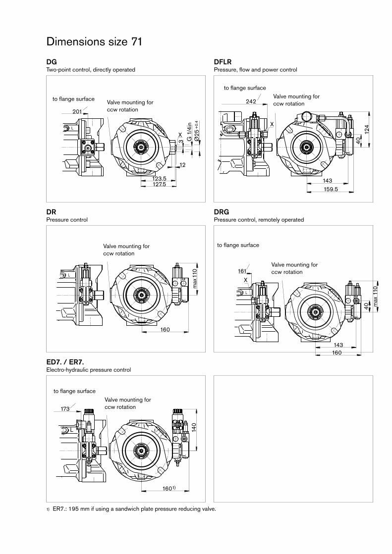
DGTwopoint control, directly operated
DFLRPressure, flow and power control
DRPressure control
DRGPressure control, remotely operated
ED7. / ER7.Electrohydraulic pressure control
ER7.: 195 mm if using a sandwich plate pressure reducing valve.1)
Dimensions size 71
173
140
X
1601)
L
L
201
12
3 G 1
/4in
Ø25
+0.
4
127.5123.5
X
L 110
max
160
X
40
X
242
143159.5
124
L 110
max
143160
40
161
X
X
Valve mounting for ccw rotation
Valve mounting for ccw rotation
Valve mounting for ccw rotation
Valve mounting for ccw rotation
Valve mounting for ccw rotation
to flange surface
to flange surface
to flange surface
to flange surface

Dimensions size 100DFR/DFR1 – Pressure and flow control, hydraulic Clockwise rotation
PortsDesignation Port for Standard Size1) Maximum
pressure [bar]2)State
B Service line, fastening thread
SAE J5183) DIN 13
1 1/4 in M14 x 2; 19 deep
350 O
S Suction line, fastening thread
SAE J5183) DIN 13
2 1/2 in M12 x 1.75; 17 deep
10 O
L Case drain fluid DIN 38524) M27 x 2; 16 deep 2 O5)
L1 Case drain fluid DIN 38524) M27 x 2; 16 deep 2 X5)
X Pilot pressure DIN 38524) M14 x 1.5; 12 deep 350 O
X Pilot pressure with DGcontrol DIN ISO 2284) G 1/4 in 350 O
X
Ø32
66.7
31.8
B
S
88.9
Ø60
50.8
40
148.4
164.9317
329
100
100
180210
118
17.5
152
106
95
W
VX
L
L1
6229
2095
275
17512.7
max
. 110
Ø12
5-0
.063
0
45°
Detail V Detail W
Flange ISO 30192
Valve mounting for ccw rotation
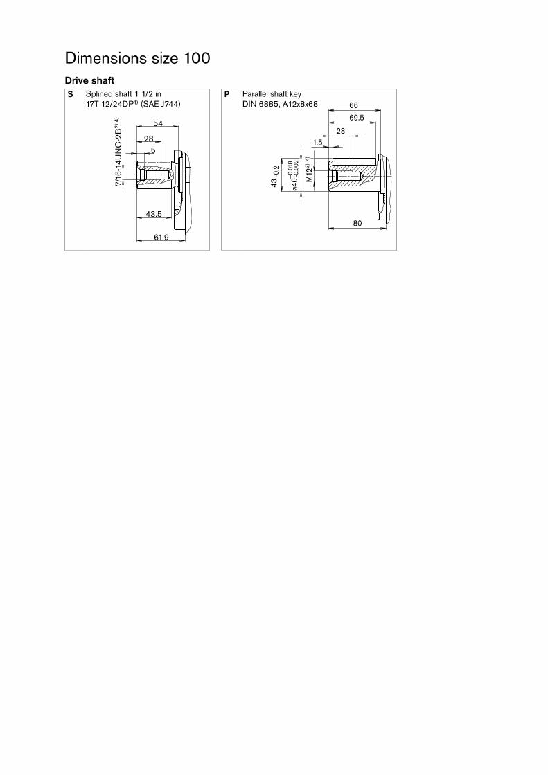
Drive shaftS Splined shaft 1 1/2 in
17T 12/24DP1) (SAE J744)P Parallel shaft key
DIN 6885, A12x8x68
Dimensions size 100
61.9
285
54
43.5
7/16
-14U
NC
-2B
2) 4
)
ø40 M
123)
, 4)
43 -0
.2
80
1.528
66
69.5
+0.
018
-0.0
02
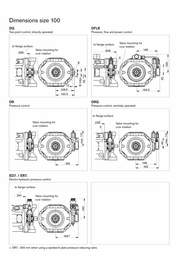
DGTwopoint control, directly operated
DFLRPressure, flow and power control
DRPressure control
DRGPressure control, remotely operated
ED7. / ER7.Electrohydraulic pressure control
ER7.: 200 mm when using a sandwich plate pressure reducing valve.1)
Dimensions size 100
X
165
max
. 110
X
40148165
X
228
max
. 110
148
40
164.5
129
X
308268
1225
+0.
4R
1/4
in3
128.5
132.5
X
140
1651)
X
241
Valve mounting for ccw rotation
Valve mounting for ccw rotation
Valve mounting for ccw rotation
Valve mounting for ccw rotation
Valve mounting for ccw rotation
to flange surfaceto flange surface
to flange surface
to flange surface

Dimensions size 140DFR/DFR1 – Pressure and flow control, hydraulic Clockwise rotation
PortsDesignation Port for Standard Size1) Maximum
pressure [bar]2)State
B Service line, fastening thread
SAE J5183) DIN 13
1 1/4 in M14 x 2; 19 deep
350 O
S Suction line, fastening thread
SAE J5183) DIN 13
2 1/2 in M12 x 1.75; 17 deep
10 O
L Case drain fluid DIN 38524) M27 x 2; 16 deep 2 O5)
L1 Case drain fluid DIN 38524) M27 x 2; 16 deep 2 X5)
X Pilot pressure DIN 38524) M14 x 1.5; 12 deep 350 O
X Pilot pressure with DGcontrol DIN 38524) M14 x 1.5; 12 deep 350 O
MH Gauge port, high pressure DIN 3852 M14 x 1.5, 12 deep 350 X
L
88.9
66.7
S
BØ32
31.8
Ø63
50.8
110
110
275
158.
420
0
131
20.6
V
W
45°
2178
Ø18
0-0
.063
0
X
L1
L L
337
244
118.5
126
183209
112
2610
8
158.4200
17312.7
6.4
Detail V Detail W
Flange 30192
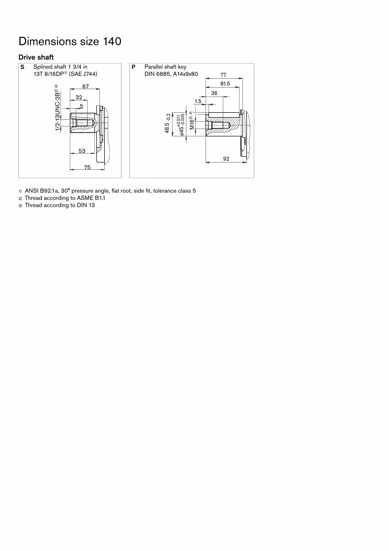
Drive shaftS Splined shaft 1 3/4 in
13T 8/16DP1) (SAE J744)P Parallel shaft key
DIN 6885, A14x9x80
ANSI B92.1a, 30° pressure angle, flat root, side fit, tolerance class 51)
Thread according to ASME B1.12)
Thread according to DIN 133)
Dimensions size 140
75
32
5
67
53
1/2-
13U
NC
-2B
2) 4
)
ø45 M
163)
, 4)
48.5
-0.2
92
1.536
77
81.5
+0.
011
-0.0
05
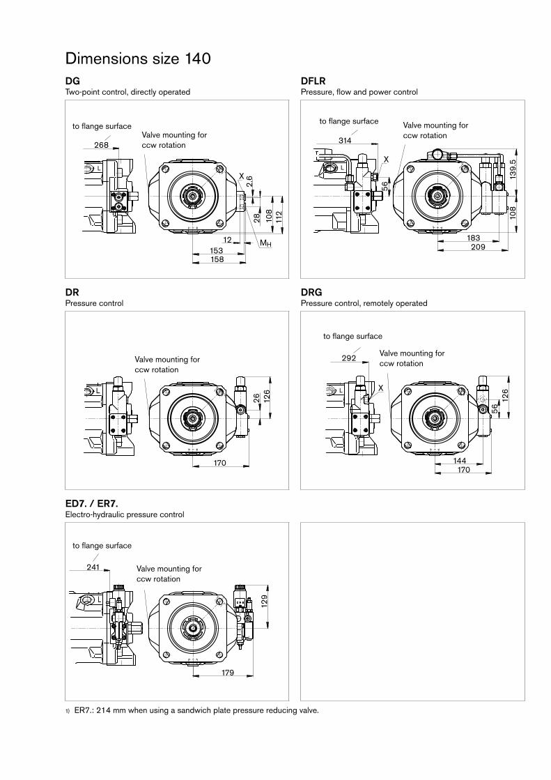
DGTwopoint control, directly operated
DFLRPressure, flow and power control
DRPressure control
DRGPressure control, remotely operated
ED7. / ER7.Electrohydraulic pressure control
ER7.: 214 mm when using a sandwich plate pressure reducing valve.1)
Dimensions size 140
L
108
112
28153
12
158
MH
X
2.6
268
L
139.
5X
314
108
56
183209
L
170
26 126 L
126
56
292
X
170144
129
179
241
L
X
Valve mounting for ccw rotation
Valve mounting for ccw rotation
Valve mounting for ccw rotation
Valve mounting for ccw rotation
Valve mounting for ccw rotation
to flange surfaceto flange surface
to flange surface
to flange surface
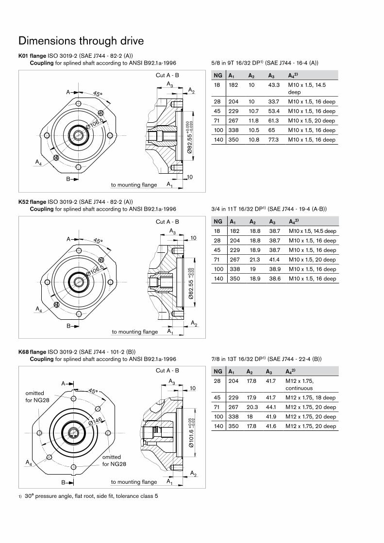
Dimensions through driveK01 flange ISO 30192 (SAE J744 822 (A)) Coupling for splined shaft according to ANSI B92.1a1996 5/8 in 9T 16/32 DP1) (SAE J744 164 (A))
K52 flange ISO 30192 (SAE J744 822 (A)) Coupling for splined shaft according to ANSI B92.1a1996 3/4 in 11T 16/32 DP1) (SAE J744 194 (AB))
K68 flange ISO 30192 (SAE J744 1012 (B)) Coupling for splined shaft according to ANSI B92.1a1996 7/8 in 13T 16/32 DP1) (SAE J744 224 (B))
NG A1 A2 A3 A42)
18 182 10 43.3 M10 x 1.5, 14.5 deep
28 204 10 33.7 M10 x 1.5, 16 deep
45 229 10.7 53.4 M10 x 1.5, 16 deep
71 267 11.8 61.3 M10 x 1.5, 20 deep
100 338 10.5 65 M10 x 1.5, 16 deep
140 350 10.8 77.3 M10 x 1.5, 16 deep
NG A1 A2 A3 A42)
18 182 18.8 38.7 M10 x 1.5, 14.5 deep
28 204 18.8 38.7 M10 x 1.5, 16 deep
45 229 18.9 38.7 M10 x 1.5, 16 deep
71 267 21.3 41.4 M10 x 1.5, 20 deep
100 338 19 38.9 M10 x 1.5, 16 deep
140 350 18.9 38.6 M10 x 1.5, 16 deep
NG A1 A2 A3 A42)
28 204 17.8 41.7 M12 x 1.75, continuous
45 229 17.9 41.7 M12 x 1.75, 18 deep
71 267 20.3 44.1 M12 x 1.75, 20 deep
100 338 18 41.9 M12 x 1.75, 20 deep
140 350 17.8 41.6 M12 x 1.75, 20 deep
30° pressure angle, flat root, side fit, tolerance class 51)
Ø106.5
45°
B
A
10
Ø82
.55
+0.
050
–0.0
20
A4
A3A2
A1
Ø106.5
45°
B
A
A4
A3
A2A1
Ø82
.55
+0.
05–0
.02
10
A
B
A4
45°
Ø10
1.6
+0.
05–0
.02
A2A1
A310
Ø146
Cut A B
Cut A B
Cut A B
omitted for NG28
omitted for NG28
to mounting flange
to mounting flange
to mounting flange

Dimensions through driveK04 flange ISO 30192 (SAE J744 1012 (B)) Coupling for splined shaft according to ANSI B92.1a1996 1 in 15T 16/32 DP1) (SAE J744 254 (BB))
K07 flange ISO 30192 (SAE J744 1272 (C)) Coupling for splined shaft according to ANSI B92.1a1996 1 1/4 in 14T 12/24 DP1) (SAE J744 324 (C))
K24 flange ISO 30192 (SAE J744 1272 (C)) Coupling for splined shaft according to ANSI B92.1a1996 1 1/2 in 17T 12/24 DP1) (SAE J744 384 (CC))
NG A1 A2 A3 A42)
71 267 21.8 58.6 M16 x 2, continuous
100 338 19.5 56.4 M16 x 2, continuous
140 350 19.3 56.1 M16 x 2, 24 deep
NG A1 A2 A33) A3a
4) A42)
100 338 10.5 65 – M16 x 2, continuous
140 350 10.8 75 – M16 x 2, 24 deep
350 10.3 – 69.1 M16 x 2, 24 deep
NG A1 A2 A3 A42)
45 229 18.4 46.7 M12 x 1.75, 18 deep
71 267 20.8 49.1 M12 x 1.75, 20 deep
100 338 18.2 46.6 M12 x 1.75, 20 deep
140 350 18.3 45.9 M12 x 1.75, 20 deep
30° pressure angle, flat root, side fit, tolerance class 51)
A
B
A4
45°
Ø10
1.6
+0.
05–0
.02
A2A1
A310
Ø146
45°A
B
Ø181
Ø12
7+
0.05
–0.0
2
A2A1
A3
A4
13
Ø181
45°A
B
A2A1
A3
A4
A3a
13
Ø12
7+
0.05
–0.0
2
Cut A B
Cut A B
Cut A B
omitted for NG71
omitted for NG71
to mounting flange
to mounting flange
to mounting flange
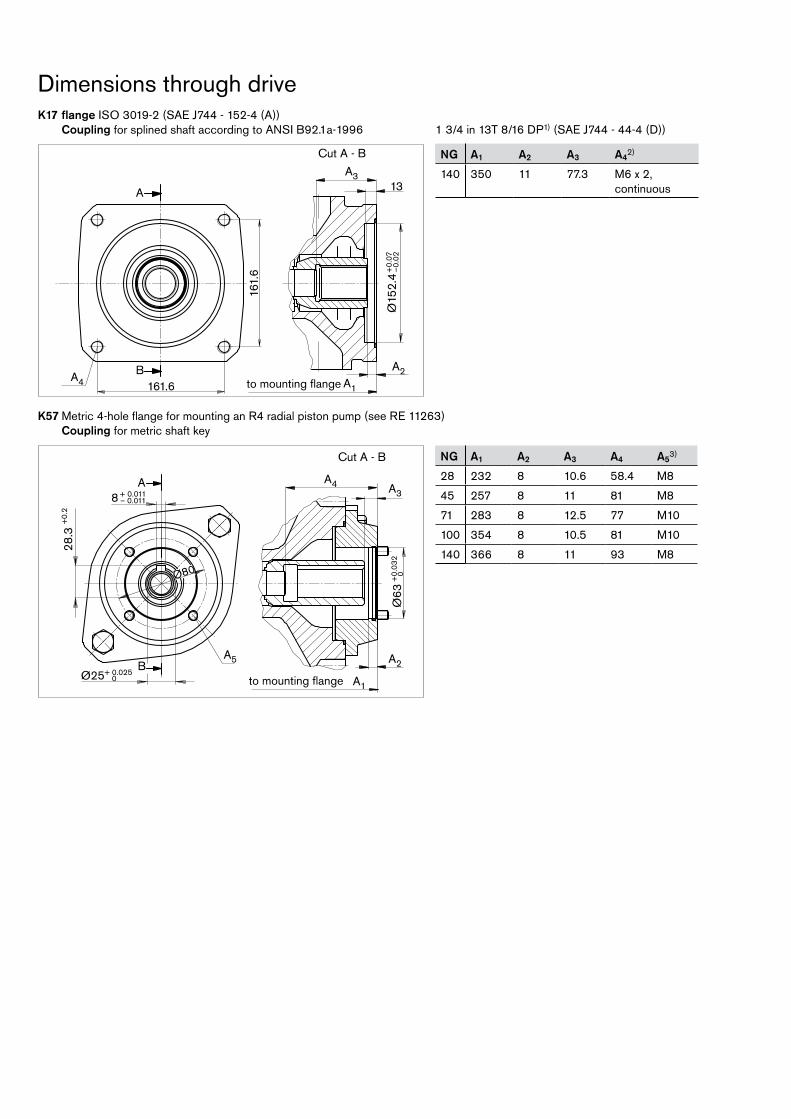
Dimensions through driveK17 flange ISO 30192 (SAE J744 1524 (A)) Coupling for splined shaft according to ANSI B92.1a1996 1 3/4 in 13T 8/16 DP1) (SAE J744 444 (D))
NG A1 A2 A3 A42)
140 350 11 77.3 M6 x 2, continuous
K57 Metric 4hole flange for mounting an R4 radial piston pump (see RE 11263) Coupling for metric shaft key
NG A1 A2 A3 A4 A53)
28 232 8 10.6 58.4 M8
45 257 8 11 81 M8
71 283 8 12.5 77 M10
100 354 8 10.5 81 M10
140 366 8 11 93 M8
Cut A B
A
B A2A1
A4
A313
Ø15
2.4
+0.
07–0
.02
161.
6
161.6
A2
A1
A4 A3A
B
28.3
+0.
2
Ø25+ 0.0250
Ø80
8 + 0.011– 0.011
A5
Ø63
+0.
032
0
Cut A B
to mounting flange
to mounting flange
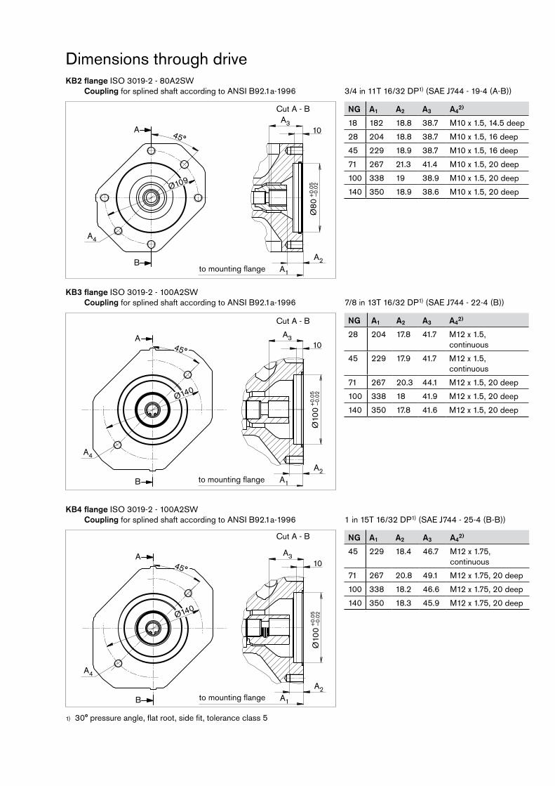
Dimensions through driveKB2 flange ISO 30192 80A2SW Coupling for splined shaft according to ANSI B92.1a1996 3/4 in 11T 16/32 DP1) (SAE J744 194 (AB))
KB3 flange ISO 30192 100A2SW Coupling for splined shaft according to ANSI B92.1a1996 7/8 in 13T 16/32 DP1) (SAE J744 224 (B))
KB4 flange ISO 30192 100A2SW Coupling for splined shaft according to ANSI B92.1a1996 1 in 15T 16/32 DP1) (SAE J744 254 (BB))
NG A1 A2 A3 A42)
18 182 18.8 38.7 M10 x 1.5, 14.5 deep
28 204 18.8 38.7 M10 x 1.5, 16 deep
45 229 18.9 38.7 M10 x 1.5, 16 deep
71 267 21.3 41.4 M10 x 1.5, 20 deep
100 338 19 38.9 M10 x 1.5, 20 deep
140 350 18.9 38.6 M10 x 1.5, 20 deep
NG A1 A2 A3 A42)
28 204 17.8 41.7 M12 x 1.5, continuous
45 229 17.9 41.7 M12 x 1.5, continuous
71 267 20.3 44.1 M12 x 1.5, 20 deep
100 338 18 41.9 M12 x 1.5, 20 deep
140 350 17.8 41.6 M12 x 1.5, 20 deep
NG A1 A2 A3 A42)
45 229 18.4 46.7 M12 x 1.75, continuous
71 267 20.8 49.1 M12 x 1.75, 20 deep
100 338 18.2 46.6 M12 x 1.75, 20 deep
140 350 18.3 45.9 M12 x 1.75, 20 deep
30° pressure angle, flat root, side fit, tolerance class 51)
45°
A2A1
A4
A310
Ø80
+0.
05–0
.02Ø109
A
B
A
B
A4
45°
Ø10
0+
0.05
–0.0
2
A2A1
A310
Ø140
A
B
A4
45°
Ø10
0+
0.05
–0.0
2
A2A1
A310
Ø140
Cut A B
Cut A B
Cut A B
to mounting flange
to mounting flange
to mounting flange

NG A1 A2 A33) A3a
4) A42)
100 338 10.5 65 – M16 x 2, continuous
140 350 10.8 75 – M16 x 2, 24 deep
350 10.3 – 69.1 M16 x 2, 24 deep
Dimensions through driveKB5 flange ISO 30192 125A2SW Coupling for splined shaft according to ANSI B92.1a1996 1 1/4 in 14T 12/24 DP1) (SAE J744 324 (C))
KB6 flange ISO 30192 125A2SW Coupling for splined shaft according to ANSI B92.1a1996 1 1/2 in 17T 12/24 DP1) (SAE J744 384 (CC))
KB7 flange ISO 30192 180B4HW Coupling for splined shaft according to ANSI B92.1a1996 1 3/4 in 13T 8/16 DP1) (SAE J744 444 (D))
NG A1 A2 A3 A42)
140 350 11.3 77.3 M16 x 2, continuous
NG A1 A2 A3 A42)
71 267 21.8 58.6 M16 x 2, continuous
100 338 19.5 56.4 M16 x 2, continuous
140 350 19.3 56.1 M16 x 2, 24 deep
30° pressure angle, flat root, side fit, tolerance class 51)
45°A
B
Ø180
12
Ø12
5+
0.05
-0.0
2
A2A1
A3
A4
10
Ø181
45°A
B
A2A1
A3
A4
A3a
10
Ø12
5+
0.05
–0.0
2
A
B A2A1
A4
A310
Ø18
0+
0.05
–0.0
2
158.
4
158.4
Cut A B
Cut A B
Cut A B
omitted for NG71
omitted for NG71
to mounting flange
to mounting flange
to mounting flange


![Ch 5: ARIMA model · 1.1 Non-Stationary Data [ToC] Dow Jones Index From Aug. 28 to Dec. 18, 1972 l l l l l ll l l l l l l l l l l l l l l l l l l l l l l l l l l l l l l l l l l l](https://static.fdocuments.us/doc/165x107/5ee0213ead6a402d666b5f8b/ch-5-arima-model-11-non-stationary-data-toc-dow-jones-index-from-aug-28-to.jpg)


![%UDFNHWV [CT] High School 106content.ciacsports.com/pdfs/wrestling_open_info_2020.pdf[L1]James Lunt Xavier - Gr12 L L L L L L L L L L L L L L L L L L L L L L L L &,$&6WDWH2SHQ3UHOLPLQDU\%UDFNHWV](https://static.fdocuments.us/doc/165x107/6056cf3169537459b5566dee/udfnhwv-ct-high-school-l1james-lunt-xavier-gr12-l-l-l-l-l-l-l-l-l-l-l-l-l.jpg)