Type ANV… ANH… - HOUDEC INNOVATIONhoudec.com/uploads/pdf/alarmes-de-niveau/HOUDEC... ·...
8
Technical data Sheet 50466-609 October 2008 Level Switch Houdec Instrument SAS Type ANV… - ANH… MAGNETIC LEVEL SWITCH
Transcript of Type ANV… ANH… - HOUDEC INNOVATIONhoudec.com/uploads/pdf/alarmes-de-niveau/HOUDEC... ·...

Technical data Sheet 50466-609 October 2008 Level Switch
Houdec Instrument SAS
Type ANV… - ANH… MAGNETIC LEVEL SWITCH

Magnetic Level Switches
Technical data Sheet 50466-609
October 2008
Page 2
Code
H
Code
C
Code
M
Code
P
Use
The vertical (series ANV) or horizontal (series ANH) level switches are designed to detect level variations in tanks containing liquids. The alarm switches commute electric or pneumatic circuits to switch relays, pumps, electric valves… or control luminous signal or alarms. They can be used for normal, corrosive or dangerous liquids with particular severe conditions of most industrial processes.
Principle
A stainless steel float follows the liquid level variations and transmits its movement to a rod equipped with an emitter. The rod and emitter assembly moves into a scaled non-magnetic guide-tube and magnetically controls the changeover of the switch which is protected by a waterproof of ADF case-housing. The ANV models must be mounted vertically, either directly on the top of the tank (series ANV-T) or on the side of the tank through an independent chamber fitted with two side connections (series ANV-C) The ANH models must be mounted horizontally, directly on the side of the tank or through an independent chamber (type ANH-C).
Description This equipment consists of standard components case switches and customized connection and chamber.
ORDERING Information - Coding Example:
ANV CM EX – CP -AC – 20 –CC6 – PO – MO – H – S – Z – D I I I I I I I I I I I I I
Design type Construction type
Housing type
Emitter Material type
Rating Flange
Connection type
Drain type
Float type Care Housing
Type
Switch type
Option types
Documents
see Page 3
see Page 3
see Page 3
see Page 4
see Page 8
see Page 8
see Page 5
see Page 5
see Page 6
see Page 2
see Page 4
see Page 8
CONSTRUCTION CODING = CODAP 2005 div1 or div2 – Instructions for pressure instruments 97/23/CE – module H or
H1 / Electric equipments: STD, ATEX //ISO 9001/2000 Certification
Body According to process condition standard carbon steel (AC) and 316L stainless steel (SS)
Normalized Flanges according to process condition, Bolts and gaskets according to process
condition
Drain For draining according to customer process
or application
Extension High temperature extension
Name plate Manufacturer name plate including all main technical data and specifications according to applicable rules and standards. In stainless steel French/ English in
standard.
Alarm Contacts According to CP piston emitter or MA magnet emitter. Standard version or
ATEX flame-proof version (EExd.)
Process Connections Many options for process tank
connections.
Case Housing According to process condition STD, EX, R
Float
Follows the variations of liquid inside the chamber. Types and pressure rating on request.
Code
C
Code
S

Technical data Sheet
50466-609 October 2008 Magnetic Level Switch
Page 3
TYPES OF CONSTRUCTION
Top Mounting Version Series
ANV…T…
Designed for direct mounting on the container through an adapted flange.
Flange materials:
Carbon steel BF48N/A105
Stainless steel 316L or 304L Other materials on request
Detailed characteristics see table on pages 4 and 5
Machined Welded Chamber Series
ANV…CM… Chamber model with machined welded elements. It
allows realisation according to customer requirement.
Materials:
Carbon steel version
Stainless steel version 316L (304L in option)
Other materials on request
TYPES OF MEASURE
Float Version see code M Used as standard for normal
applications Min. specific gravity: 0.65
Max. operating pressure: 100 bars
Max. operating temperature: 350°C Material: stainless steel Z2CND17-
12(316L)
Other material on request
NOTA: The adjustment of switching levels must only be made by changing
the float position on the rod or on the
cable. DO NOT CHANGE THE POSITION
OF THE MECHANISM IN THE
CASE HOUSING
Detailed characteristics see table on
page 6
Mass Version Mainly used for industrial processes with a high
pressure/temperature couple and/or low specific gravity. Used when the buoyancy force is not sufficient to move
the float/emitter assembly.
The float is replaced by a mass hanged to a spring. When the level gets higher, the buoyancy force on the
mass reduces the tractive force on the spring which
contracts. The assembly mass/emitter gets higher and switches on
the contact in the case-housing. When the level gets
down, the buoyancy force on the mass decreases, the spring spreads itself, the assembly mass/emitter gets
down again and the switch returns to its initial position.
It is possible to use two independent masses to control two distinct switches or to create an important re-
engaging differential.
Min. specific gravity: 0.45 Max. operating pressure: 400 bars
Max. operating temperature: 350°C
Material: stainless steel Z2CND17-12(316L), other material on request.
Double level models/double float on request
TYPE OF CASE HOUSING
Standard case-housing – IP54 Waterproof case housing IP54, enabling
the adjustment of the alarm switches. Electrical cable entry with cable gland,
connectors, connections according to
the needs (360° orientation)
Material :
Base: alloy epoxy polyester painted Cover : anodised aluminium
Option : protection rating IP65
Code H0
H1
H2
H3
H4
H5
H6
H7
H8
H9
H10
H12
HX
Designation Standard IP54 with 1 cable gland PG11 for diam. 8 to 10 cable
Standard IP54 with 2 cable glands PG11 for diam. 8 to 10 cable
Standard IP54 with 1 brass gland PG16 for diam. 10 to 15 cable
Standard IP54 with 1 cable gland M20 X 1.5 BV2 for diam. 8.5
to 14.5 cable
Standard IP54 with 1 tap M20 X 1.5
Lengthened housing (height dimension 230 becomes 330)
Heat dissipater (according to the switch type)
High temperature extension
3 pins SOURIAU male plug (Stainless steel)
7 pins SOURIAU male plug (Stainless steel)
Waterproof IP65
3 pins SOURIAU female (Stainless steel)
Special
Explosive proof case-housing
EEx dIICT6 – IP66 Code = Ex Waterproof case housing enable to put alarm switches in electrical cable
entry with cable gland, connectors,
connections according to the needs and the type of contact.
Material :
Base: alloy epoxy polyester painted
Cover : alloy epoxy polyester painted
Code H0
H1
H2
H3
H4
H5
H6
H7
H11
H13
H14
HX
Designation Standard IP66 with 1 tapped entry ¾” NPT
Standard IP66 with 2 tapped entries ¾” NPT
Aluminium cable gland for diam. 5 to 12 cable
Bronze cable gland for diam. 9 to 15 cable
Brass nickel plated steel reduction ¾” NPT- M20 X 1.5
Lengthened housing (height quotation 300 becomes 400)
Heat dissipater (according to the switch type)
High temperature extension
Brass nickel plated cable gland armoured cable diam. 6.5 to 12,
diam.10.5 to 16
Brass nickel plated adaptator 3/4NPT / M20 X 1.5
Brass nickel plated adaptator 3/4NPT / 1/2NPT
Special
.

Magnetic Level Switches
Technical data Sheet 50466-609
October 2008
Page 4
TYPE OF SWITCHES
- Switches actuated by stainless steel magnetic piston (CP)
REED SWITCH
Model :
Simple
Double
CODE
S0
S1
Characteristics U~
U= 24 48 110 230
I.Res.
(A)
1
1
1
1
0.55
0.75
0.25
0.35
Changeover switch
Screwed electric connection S=2.5mm²
*Operating temperature : -40°C à +100°C
IS REED SWITCH
Model :
Simple
Double
CODE
S15
S16
Characteristics
Change over switch
Certificate : ATEX N° LCIE05ATEX6034X
Marking: II 1 G ExiaIICT6/T5/T4
Electric Parameters: Ui≤30V; li≤50mA; Pi≤400mW Ci=0nF ; Li=0mH
Screwed electric connection S=2.5mm²
*Operating temperature : T6: Ta=50°C max./ T5:Ta=65°C max./ T4: Ta=80°C max
MICROSWITCH
Model :
Simple
Double
CODE
S2
S3
Characteristics
U~ 24 48 110 230
U=
I. Rés.
(A)
4 4 5 3
4 4 3 2
I. Ind.
(A)
2 2 2 2
2 2 0.5 0.2
Changeover switch
Screwed electric connection S=2.5mm²
*Operating temperature : -25°C to +85°C
PNEUMATIC SWITCH
Model :
Simple
CODE
S6
Characteristics
Series changeover
Supply circuit : filtered air 1 to 6bar
Connection in / out : 1/4"NPT-F
*Operating temperature : -15°C to +60°C
- Switches actuated by magnet (MA)
CONTACTS TYPE MICROSWITCH HERMETICALLY SEALED
Model :
Simple
Double
CODE
S7
S8
Characteristics
U~ 24 48 110 230
U=
I. Rés.
(A)
7 5 3 2.5
4 3 1
I. Ind.
(A)
5 3 2 1.5
2.5 1.8 0.5
Changeover switch
Screwed electric connection S=2.5mm²
*Operating temperature : -30°C à +65°C
Options : **Operating temperature : -55°C à +155°C
REED SWITCH
Model :
Simple
Double
CODE
S9
S10
Characteristics
U~ 24 48 110 230
U=
I. Rés.
(A)
1 1 0.55 0.25
1 1 0.75 0.35
Changeover switch
Screwed electric connection S=2.5mm²
*Operating temperature : -40°C à +100°C
IS REED SWITCH
Modèle :
Simple
Double
CODE
S17
S18
Characteristics
Change over switch
Certificate : ATEX N° LCIE05ATEX6034X
Marking: II 1 G ExiaIICT6/T5/T4
Paramètres électriques: Ui≤30V; li≤50mA; Pi≤400mW Ci=0nF ; Li=0mH
Screwed electric connection S=2.5mm²
*Operating temperature : T6: Ta=50°C max./ T5:Ta=65°C max./ T4: Ta=80°C max
*Allowable temperature at the switch level
For an allowable temperature inside (with ambient T°<40°C) it is possible to increase the maximum temperature by 80°C with standard design, by 130°C with H6 option, by
230°C with H6+H7 option.
For the explosion proof version, liquid and ambient T° must be in accordance with explosion proof certificate.
MA*= Used with switches actuated by magnet (see page 3)
CP*= Used with switches actuated by magnetic stainless steel piston (see page 3)
Interface level measures on request.

Technical data Sheet
50466-609 October 2008 Magnetic Level Switch
Page 5
CHARACTERISTICS AND CHOICE OF CONNECTION ACCORDING TO THE TYPE OF CONSTRUCTION
ANV-T TOP MOUNTING
Carbone steel version Stainless steel version 304 L Stainless steel version 316L CODE PN…* DN… CODE PN…* DN… CODE PN…* DN…
CO …* 80 (3”) C3 …* 80 (3”) C6 …* 80 (3”)
C1 …* 100 (4”) C4 …* 100 (4”) C7 …* 100 (4”)
C2 …* 150 (6”) C5 …* 150 (6”) C8 …* 150 (6”)
ANV – CM With Mechanically Machined Welded Chamber DN 80 (3”) (Side-bottom = CF, Side-side = CC, Drain = P)
CODE TYPE OF
CONNECTION
CONNECTION
DRAWINGS
NOTES
CF0 Socket Weld 1”
A and B as standard construction
and on request
- Body and Head DN80 PN … standard 20, 50, 100
- Connections : please precise: The dimension of connections ABCE
The dimension PN…DN…
- Mini 150* : depending on PN/DN flange, float type, switching level will be defined by Technical Dept
- Chamber material: Carbon steel. Fittings A105 or equivalent, flange BF48N, tube P265GH (standard or other on request)
- Chamber material: Stainless steel 316L. Flanges, fittings, tube,
cap, 316L (standardised components, other on request), 304L in option
- Standard head Gasket: Klingersil C4430 or according to service
conditions.
- Studs and Nuts: as standard carbon steel (B7-2H), stainless steel in
option
- Various options see page 8
PN EN1092 16 20 40 50 100
NP ANSI B16-5 150# 300# 600#
DN EN1092 15 20 25 40 50 80 100
ND ANSI B16-5 1/2" 3/4" 1" 1 1/2" 2" 3" 4"
CF1 Tapped ½” or ¾” NPT-F
CF2 Tapped ½” or ¾” BSPP-F
CF2 Threaded tube 1” (L<=150mm)
CF4 Flange ISO PN…DN15
CF5 Flange ISO PN…DN20
CF6 Flange ISO PN…DN25
Cf7 Flange ISO PN…DN40
CF8 Flange ISO PN…DN50
CF9 RTJ gasket facing
CFX Special on request
CC0 Socket Weld 1”
E and B as standard construction
and on request
CC1 Tapped ½” or ¾” NPT-F
CC2 Tapped ½” or ¾” BSPP-F
CC3 Threaded tube 1” (L<=150mm)
CC4 Flange ISO PN…DN15
CC5 Flange ISO PN…DN20
CC6 Flange ISO PN…DN25
CC7 Flange ISO PN…DN40
CC8 Flange ISO PN…DN50
CC9 RTJ gasket facing
CCX Special on request
P0 Socket Weld 1”
C and B as standard construction
and on request
P1 Tapped ½” or ¾” NPT-F
P2 Tapped ½” or ¾” BSPP-F
P3 Threaded tube 1” (L<=150mm)
P4 Flange ISO PN…DN15
P5 Flange ISO PN…DN20
P6 Flange ISO PN…DN25
P7 Flange ISO PN…DN40
P8 Flange ISO PN…DN50
P9 RTJ gasket facing
PX Special on request
Characteristics of Chamber Construction: Standard construction : connection welded by fillet welds, on request, full penetration weld (code Z2 see page 8)
Pressure/temperature limit of chambers according to the normalised rating
of the flanges. Design conditions for construction = Service (or design) value of
customer.
Hydrostatic test (at 20°C) = service (or design) pressure X 1.5 or X 1.2 following the max. pressure for float (see page 6)
Calculation and verification of the resistance according to CODAP (on
request see D3 page 8)
NOTA: The maximum operating pressures are limited either by the float or the flange and chamber rating.
Make sure that the tank dimensions are compatible with the necessary
measuring elements (see floats page 6)
Precise the PN (standard 16, 20, 40, 50, 100)
On request : other PN or DN On request : other materials
Pressure/temperature LIMITS (NFE 29005) for:
CARBON STEEL FLANGES STAINLESS STEEL 316 L FLANGES PN/T° 20 50 100 150 200 250 300 350 PN/T° 20 50 100 150 200 250 300 350
16 16 16 16 15.7 15.2 14.4 12.8 11.2 16 13.5 12.9 11.8 10.8 9.7 9 8.4 8
20 19.6 19.2 17.7 15.8 14 12.1 10.2 8.4 20 15.9 15.3 13.2 12 11 10.2 9.7 8.4
40 40 40 40 39.2 38 36 32 28 40 33.8 32.4 29.5 27 24.4 22.6 21 20.1
50 51.1 50.1 46.4 45.2 43.8 41.7 38.7 37 50 41.4 40 34.5 31.2 28.7 26.7 25.2 24
100 102.1 100.2 92.8 90.5 87.6 83.4 77.5 73.9 100 82.7 79.9 69 62.5 57.4 53.4 50.5 48.1
*

Magnetic Level Switches
Technical data Sheet 50466-609
October 2008
Page 6
CHOICE OF THE FLOAT OR MASS
Nota: the characteristics mentioned hereafter are valid only if the chamber receiving the float or the mass, has harmonized characteristics.
Min
spec
ific
gra
vit
y
Max
aper
at.
Pre
ssure
(20°C
) TYPE OF FLOAT
OR MASS CODE
CHARACTERISTICS
Mini specific gravity
according to level
Standard operating pressure (bar) according to max.
operating temperature C°
Test pressure
20°C
TOP MOUNTING > 4"
0.70
à
0.85
27
à
33
bar
M3 Stainless
steel
material
316L
H MA CP Temp.°C >> 20 50 100 150 200 250 300 350
<250 0.75 0.7 Standard 27 26 23 21 19 17.5 16 15 Test pres=Op.pres
X1.5 (<=40 bar)
<500 0.8 1.75 Maximum 33 31.5 28 25 23 21 19.5 18 Test pres=Op.pres
X1.5 (<=40 bar)
<1000 0.9 0.85
WELDED CHAMBER 3"OR TOP MOUNTING
0.85
à
1
40
à
50
bar
M0 Stainless
steel
material
316L
H MA CP Temp.°C >> 20 50 100 150 200 250 300 350
<250 0.9 0.85 Standard 40 38 34 31 28 26 24 22 Test pres=Op.pres
X1.5 (<=60 bar)
<500 0.95 0.9 Maximum 50 47.5 42 38.
5 35 32.5 30 28
Test pres=Op.pres
X1.2 (<=60 bar)
<1000 1.05 1
0.65
à
0.8
12
à
15
bar
M1 Stainless
steel
material
316L
H MA CP Temp.°C >> 20 50 100 150 200 250 300 350
<250 0.7 0.75 Standard 12 11.5 10 9 8.5 7.5 7 6 Test pres=Op.pres
X1.5 (<=18 bar)
<500 0.75 0.7 Maximum 15 14 12 11.5 10.5 9.5 9 8 Test pres=Op.pres
X1.2 (<=18 bar)
<1000 0.85 0.8
>0.6 155
à
188
bar
M5 Stainless
steel
material
316L
H MA CP Temp.°C >> 20 50 100 150 200 250 300 350
<1000 0.6 0.6 Standard 155 140 130 125 115 110 100 90 Test pres=Op.pres
X1.5 (<=230 bar)
Maximum 188 170 158 142 140 134 122 110 Test pres=Op.pres
X1.2 (<=230 bar)
>0.45
150
à
190
bar
M6 Stainless
steel
material
316L
H MA CP Temp.°C >> 20 50 100 150 200 250 300 350
<3000 0.45 0.45 Standard 150 143 126 116 105 97 88 83 Test pres=Op.pres
X1.5 (<=230 bar)
Maximum 190 180 160 147 133 123 112 104 Test pres=Op.pres
X1.2 (<=230 bar)
0.9
à
**
16
à
20
bar
M11 Stainless
steel
material
316L
H MA CP Temp.°C >> 20 50 100 150 200 250 300 350
<12000 0.9 Standard 16 14.5 13.5 13 12 11 11 11 Test pres=Op.pres
X1.5 (<=25 bar)
Maximum 20 17.5 16.5 16 14.5 13.5 13.5 13.5 Test pres=Op.pres
X1.2 (<=25 bar)
FLOATING ROOF
0
à
400
bar
M10 Stainless
steel
material
316L
H MA CP Temp.°C >> 20 50 100 150 200 250 300 350
<6000 -- -- Standard
T pres=Op.pres X1.5
=T.pres of chamber
Maximum
T pres=Op.pres X1.5
=T.pres of chamber
FLOAT FOR 4" chamber or TOP
Min
spec
ific
gra
vit
y
Max
aper
at.
Pre
ssure
(20°C
) TYPE OF FLOAT OR MASS
According to flange or chamber
CODE CHARACTERISTICS
Mini specific gravity
according to level
Standard operating pressure (bar) according to max. operating
temperature C°
Test pressure
20°C
>0.75 102
M8 Stainless
steel
material
316
H MA Temp.°C >> 20 50 100 150 200 250 300 350
<250 0.75 Standard 102 88 79 73 69 66 63 61 Test pres= 127 bar
<500 0.78
<1000 0.82
>0.66 50
M9 Stainless
steel
material
316
H MA Temp.°C >> 20 50 100 150 200 250 300 350
<250 0.66 Standard 51 44 39 37 34.5 33 31.5 30 Test pres= 63 bar
<500 0.7
<1000 0.8
Non limited till 400bar
Non limited till 400bar
Ø76x66 ép2
Ø80x30
Ø85x160
Ø85x160
Technical data Sheet
50466-609 October 2008 Magnetic Level Switch
Page 7
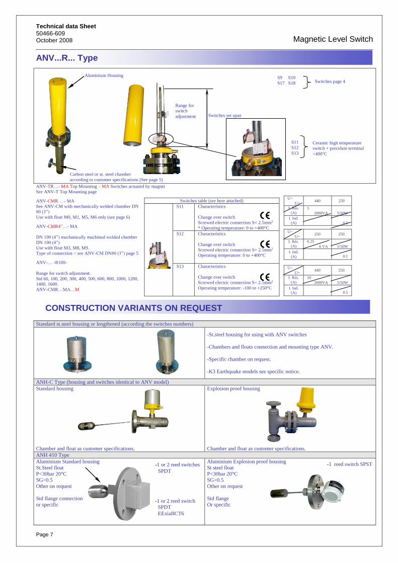
ANV...R... Type
ANV-TR…- MA Top Mounting – MA Switches actuated by magnet
See ANV-T Top Mounting page
ANV-CMR… - MA
See ANV-CM with mechanically welded chamber DN
80 (3”)
Use with float M0, M1, M5, M6 only (see page 6)
ANV-CMR4”…- MA
DN 100 (4”) mechanically machined welded chamber
DN 100 (4”)
Use with float M3, M8, M9.
Type of connection = see ANV-CM DN80 (3”) page 5
ANV-… -R100-
Range for switch adjustment.
Std 60, 100, 200, 300, 400, 500, 600, 800, 1000, 1200,
1400, 1600.
ANV-CMR…MA…M
CONSTRUCTION VARIANTS ON REQUEST
Standard st.steel housing or lengthened (according the switches numbers)
-St.steel housing for using with ANV switches
-Chambers and floats connection and mounting type ANV.
-Specific chamber on request.
-K3 Earthquake models see specific notice. ANH-C Type (housing and switches identical to ANV model)
Standard housing
Chamber and float as customer specifications.
Explosion proof housing
Chamber and float as customer specifications.
ANH 410 Type
Aluminium Standard housing
St.Steel float
P<30bar 20°C SG>0.5
Other on request
Std flange connection
or specific
Aluminium Explosion proof housing
St steel float
P<30bar 20°C SG>0.5
Other on request
Std flange
Or specific
U~ 440 250
U=
I. Rés.
(A)
5
2000VA 5/50W
I. Ind.
(A)
0.5
Switches table (see here attached)
S11 Characteristics
Change over switch
Screwed electric connection S= 2.5mm2
* Operating temperature: 0 to +400°C
S12 Characteristics
Change over switch
Screwed electric connection S= 2.5mm2
Operating temperature: 0 to +400°C
S13 Characteristics
Change over switch
Screwed electric connection S= 2.5mm2
Operating temperature: -100 to +250°C
U~ 250 250
U=
I. Rés.
(A)
0.25
6 VA 5/50W
I. Ind.
(A)
0.1
U~ 440 250
U=
I. Rés.
(A)
10
2000VA 5/50W
I. Ind.
(A)
0.5
-1 or 2 reed switches
SPDT
-1 or 2 reed switch
SPDT
EExiaIICT6
-1 reed switch SPST
Switches set span
Aluminium Housing
Carbon steel or st. steel chamber
according to customer specifications (See page 5)
Range for
switch
adjustment
S9 S10
S17 S18 Switches page 4
S11
S12
S13
Ceramic high temperature
switch + porcelain terminal
<400°C

Magnetic Level Switches
Technical data Sheet 50466-609
October 2008
Page 8
copyright information
Houdec Instrument S.A.S.
Z.A. de la Tour– ABREST– France
Tel: +33 (0)4.70.59.81.81.
Fax: +33 (0)4.70.59.96.37.
www.houdec.com
GENERAL CODIFICATION
ANV Level Switch (vertical mounting)
ANH Level Switch (horizontal mounting)
T Standard case-housing, top mounting
TR Top Mounting type R housing
TEX Explosion proof case-housing, top mounting
CM Welded chamber with standard case-housing
CMR Welded chamber with type R Housing
CMEX Welded chamber with explosion proof case-housing
CP Construction with piston emitter
MA Construction with magnetic emitter
AC Carbon steel model
SS Stainless steel model
*** Nominal connection pressure: 16,20,40,50,100…
C0 to C… Top mounting
CF0 to CF… Side-bottom mounting
CC0 to CC… Side-side mounting
P0 to P… Type of drain for welded chamber
M0 to M… Float or mass code
H0 to H… Code for options on case-housing
S0 to S… Code for type of switch
Z0 to Z… Code for varied options
D0 to D…
Code
documents
VARIED OPTIONS Z0 Stainless steel bolts and nuts (304 or 316) Z1 Spiral head gasket Z2 Full penetration weld Z3 Welding with penetrating tube Z4 Heat treatment (for carbon steel welded chamber) Z5 Sand blasting SA 2.5 (for carbon steel chamber) Z6 Epoxy paint steel chamber (cleaning + primary epoxy + epoxy finish) Z7 Silicone paint T = 400°C (600°C for peak) (cleaning + 1 layer of silicon aluminium)
DOCUMENTS OPTIONS D0 Material certificates 3.1.B. (must be asked when the order is placed) D1 Nace standard certificate (curve and annealing diagram for carbon steel) D2 Welding book (welding procedures and welders qualification) D3 Calculation note according to CODAP (machine-welded chamber)
D4A File according to French Pressure Vessel regulation D5 Technical passport (according to definition) D6 Dye penetrant test for welds D7 10% dye penetrant test for welds by Third Party
D7A 20% dye penetrant test for welds by Third Party D8 10 % radiography for butt welds
D8A 20% radiography for butt welds D9 100 % radiography for butt welds
D10 Thickness test with cartography D11 Documentation on CD ROM D12 G/A drawing D13 Certificate of conformity and hydraulic test (not applicable if D4A)
ESSENTIAL INFORMATIONS REQUIRED FOR PLACING AN ORDER
- Nature of the liquid to choose the compatible materials - Specific gravity of the liquid (if interface: precise specific gravity of both liquids)
- Maximum operating temperature and pressure (and design if exists) - Switching level and the way of (up or down)
- Dimensions and shapes of connecting systems on tank
- Type of classification desired for case-housing (Protection class IP…, protection class in dangerous areas, EEx dIICT…, use on IS circuit…)
- Characteristics of switched circuit
(Voltage, current, power, resistive or inductive circuit, pressure and flow for pneumatic circuits…)
- Options and necessary documents