Type 90 Ti Rotor · 2 Type 90 Ti Rotor SAFETY NOTICE This safety notice summarizes information...
28
Type 90 Ti Rotor Used In Beckman Coulter Class H, R, and S Preparative Ultracentrifuges LXL-TB-005AN August 2009 © 2009 Beckman Coulter, Inc.
-
Upload
truongdiep -
Category
Documents
-
view
218 -
download
0
Transcript of Type 90 Ti Rotor · 2 Type 90 Ti Rotor SAFETY NOTICE This safety notice summarizes information...
Type 90 Ti Rotor
Used In Beckman CoulterClass H, R, and S
Preparative Ultracentrifuges
LXL-TB-005ANAugust 2009
© 2009 Beckman Coulter, Inc.
2
Type 90 Ti Rotor
SAFETY NOTICE
This safety notice summarizes information basic to the safe use of the rotor described in this manual. The international symbol displayed above is a reminder to the user that all safety instructions should be read and understood before operation or maintenance of this equip-ment is attempted. When you see the symbol on other pages throughout this publication, pay special attention to the specific safety information presented. Observance of safety precau-tions will also help to avoid actions that could damage or adversely affect the performance of the rotor. This rotor was developed, manufactured, and tested for safety and reliability as part of a Beckman Coulter ultracentrifuge/rotor system. Its safety or reliability cannot be assured if used in a centrifuge not of Beckman Coulter’s manufacture or in a Beckman Coulter ultra-centrifuge that has been modified without Beckman Coulter’s approval.
Handle body fluids with care because they can transmit disease. No known test offers complete assurance that such fluids are free of micro-organisms. Some of the most virulent—Hepatitis (B and C) viruses, HIV (I–V), atypical mycobacteria, and certain systemic fungi —further emphasize the need for aerosol protection. Handle other infectious samples according to good laboratory procedures and methods to prevent spread of disease. Because spills may generate aerosols, observe proper safety precautions for aerosol contain-ment. Do not run toxic, pathogenic, or radioactive materials in this centrifuge without taking appropriate safety precautions. Biosafe containment should be used when Risk Group II materials (as identified in the World Health Organization Laboratory Biosafety Manual) are handled; materials of a higher group require more than one level of protection.
The rotor and accessories are not designed for use with materials capable of developing flammable or explosive vapors. Do not centrifuge such materials in nor handle or store them near the ultracentrifuge.
Although rotor components and accessories made by other manufacturers may fit in the Type 90 Ti rotor, their safety in this rotor cannot be ascertained by Beckman Coulter. Use of other manufacturers’ components or accessories in the Type 90 Ti rotor may void the rotor warranty and should be prohibited by your laboratory safety officer. Only the components and accessories listed in this publication should be used in this rotor.
Make sure that filled containers are loaded symmetrically into the rotor and that opposing tubes are filled to the same level with liquid of the same density. Make sure that cavities in use have the proper spacers inserted (if applicable) before installing the rotor lid.
If disassembly reveals evidence of leakage, you should assume that some fluid escaped the rotor. Apply appropriate decontamination procedures to the centrifuge and accessories.
Never exceed the maximum rated speed of the rotor and labware in use. Refer to the section on RUN SPEEDS, and derate the run speed as appropriate.
Do not use sharp tools on the rotor that could cause scratches in the rotor surface. Corrosion begins in scratches and may open fissures in the rotor with continued use.
!
!
!
!
!
!
!
!
Type 90 Ti Rotor
* Relative Centrifugal Field (RCF) is the ratio of the centrifugal acceleration at a specified radiusand speed (rω2) to the standard acceleration of gravity (g) according to the following formula:
where r is the radius in millimeters, ω is the angular velocity in radians per second(2 π RPM /60), and g is the standard acceleration of gravity (9807 mm/s2). After substitution:
RCF rω2
g---------=
RCF 1.12 r RPM1000------------⎝ ⎠
⎛ ⎞ 2=
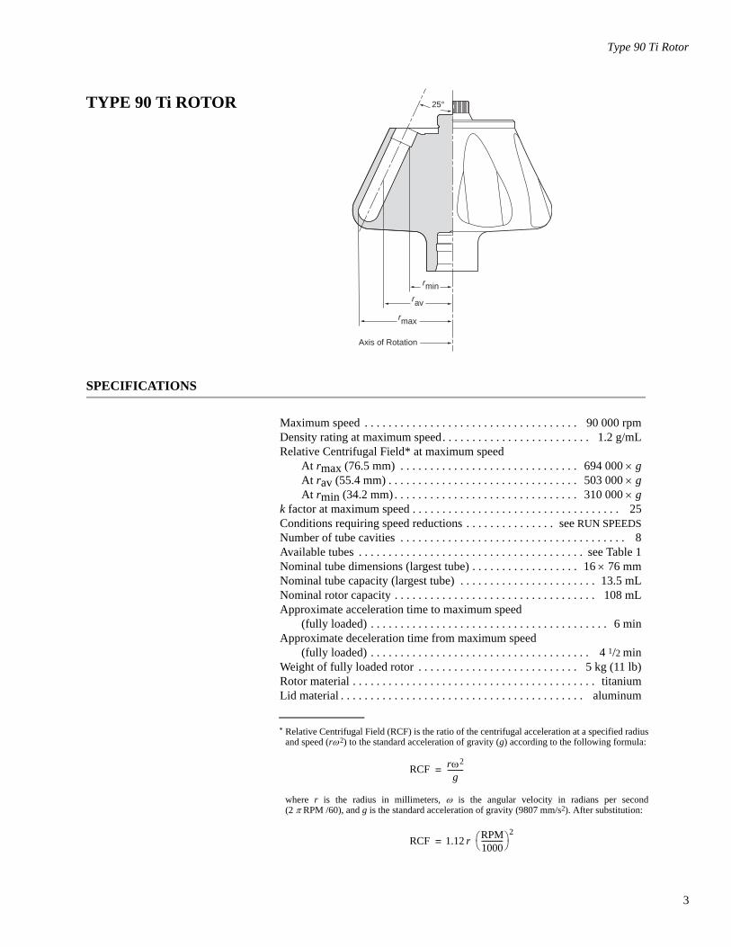
TYPE 90 Ti ROTOR
SPECIFICATIONS
Maximum speed . . . . . . . . . . . . . . . . . . . . . . . . . . . . . . . . . . . . 90 000 rpmDensity rating at maximum speed. . . . . . . . . . . . . . . . . . . . . . . . . 1.2 g/mLRelative Centrifugal Field* at maximum speed
At rmax (76.5 mm) . . . . . . . . . . . . . . . . . . . . . . . . . . . . . . 694 000 × gAt rav (55.4 mm) . . . . . . . . . . . . . . . . . . . . . . . . . . . . . . . . 503 000 × gAt rmin (34.2 mm) . . . . . . . . . . . . . . . . . . . . . . . . . . . . . . . 310 000 × g
k factor at maximum speed . . . . . . . . . . . . . . . . . . . . . . . . . . . . . . . . . . . 25Conditions requiring speed reductions . . . . . . . . . . . . . . . see RUN SPEEDSNumber of tube cavities . . . . . . . . . . . . . . . . . . . . . . . . . . . . . . . . . . . . . . 8Available tubes . . . . . . . . . . . . . . . . . . . . . . . . . . . . . . . . . . . . . . see Table 1Nominal tube dimensions (largest tube) . . . . . . . . . . . . . . . . . . 16 × 76 mmNominal tube capacity (largest tube) . . . . . . . . . . . . . . . . . . . . . . . 13.5 mLNominal rotor capacity . . . . . . . . . . . . . . . . . . . . . . . . . . . . . . . . . . 108 mLApproximate acceleration time to maximum speed
(fully loaded) . . . . . . . . . . . . . . . . . . . . . . . . . . . . . . . . . . . . . . . . 6 minApproximate deceleration time from maximum speed
(fully loaded) . . . . . . . . . . . . . . . . . . . . . . . . . . . . . . . . . . . . . 4 1/2 minWeight of fully loaded rotor . . . . . . . . . . . . . . . . . . . . . . . . . . . 5 kg (11 lb)Rotor material . . . . . . . . . . . . . . . . . . . . . . . . . . . . . . . . . . . . . . . . . titaniumLid material . . . . . . . . . . . . . . . . . . . . . . . . . . . . . . . . . . . . . . . . . aluminum
rmin rav
rmax
Axis of Rotation
25°
3

4
Type 90 Ti Rotor
DESCRIPTIONThis rotor has been manufactured in a registered ISO 9001 or 13485 facility for use with the appropriately classified Beckman Coulter ultracentrifuges.
The Type 90 Ti, rated for 90 000 rpm, is a fixed angle rotor designed to centrifuge up to eight tubes at a 25-degree angle to the axis of rotation. Used in Beckman Coulter class H, R, and S preparative ultracentrifuges, the rotor develops centrifugal forces sufficient for the differential separation of particles, and for equilibrium sedimenta-tion of particles such as DNA and viruses. Up to 108 mL of gradient and sample volume can be centrifuged per run.
The rotor is made of titanium and is finished with black polyurethane paint. The aluminum lid and handle are anodized for corrosion resis-tance. O-rings made of Buna N rubber in the lid and handle maintain atmospheric pressure inside the rotor during centrifugation, if they are properly lubricated. Because of the weight of the rotor, drive pins are not required in the rotor drive hub cavity.
For overspeed protection, a photoelectrical detector in the ultracentri-fuge monitors the overspeed disk on the rotor bottom and shuts down the run if speeds exceeding 90 000 rpm are detected.
See the Warranty at the back of this manual for warranty information.
PREPARATION AND USE
Specific information about the Type 90 Ti rotor is given here. Infor-mation common to this and other rotors is contained in Rotors and Tubes for Preparative Ultracentrifuges (publication LR-IM), which should be used together with this manual for complete rotor and accessory operation.
➠ NOTEAlthough rotor components and accessories made by other manufacturers may fit in the Type 90 Ti rotor, their safety in this rotor cannot be ascertained by Beckman Coulter. Use of other manufacturers’ components or accessories in the Type 90 Ti rotor may void the rotor warranty and should be prohibited by your laboratory safety officer. Only the components and acces-sories listed in this publication should be used in this rotor.
Handle(364392)
Lid
HandleO-Ring(839347)
LidO-Ring(876089)
Overspeed Disk(355539)
RotorBody
Type 90 Ti Rotor
PRERUN SAFETY CHECKS
Read the Safety Notice page at the front of this manual before using the rotor.
1. Make sure that the rotor and lid are clean and show no signs of corrosion or cracking.
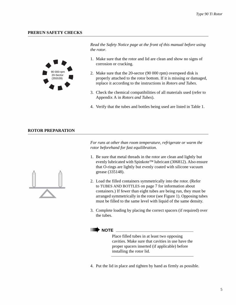
2. Make sure that the 20-sector (90 000 rpm) overspeed disk is properly attached to the rotor bottom. If it is missing or damaged, replace it according to the instructions in Rotors and Tubes.
3. Check the chemical compatibilities of all materials used (refer to Appendix A in Rotors and Tubes).
4. Verify that the tubes and bottles being used are listed in Table 1.
ROTOR PREPARATION
For runs at other than room temperature, refrigerate or warm the rotor beforehand for fast equilibration.
1. Be sure that metal threads in the rotor are clean and lightly but evenly lubricated with Spinkote™ lubricant (306812). Also ensure that O-rings are lightly but evenly coated with silicone vacuum grease (335148).
2. Load the filled containers symmetrically into the rotor. (Refer to TUBES AND BOTTLES on page 7 for information about containers.) If fewer than eight tubes are being run, they must be arranged symmetrically in the rotor (see Figure 1). Opposing tubes must be filled to the same level with liquid of the same density.
3. Complete loading by placing the correct spacers (if required) over the tubes.
➠ NOTEPlace filled tubes in at least two opposing cavities. Make sure that cavities in use have the proper spacers inserted (if applicable) before installing the rotor lid.
4. Put the lid in place and tighten by hand as firmly as possible.
90 000-rpm20-Sector(355539)
5

6
Type 90 Ti Rotor
Figure 1. Arranging Tubes in the Rotor. Two, four, six, or eight tubes can be centrifuged per run, if they are arranged in the rotor as shown.
OPERATION
1. Carefully lower the rotor straight down onto the drive hub.
2. Refer to the applicable instrument instruction manual for ultracen-trifuge operation.
3. For additional operating information, see the following:
• RUN TIMES, page 12, for using k factors to adjust run durations
• RUN SPEEDS, page 13, for information about speed limitations
• SELECTING CsCl GRADIENTS, page 15, for methods to avoid CsCl precipitation during centrifugation
REMOVAL AND SAMPLE RECOVERY
! CAUTIONIf disassembly reveals evidence of leakage, you should assume that some fluid escaped the rotor. Apply appropriate decontamination procedures to the ultracentrifuge and accessories.
1. Remove the rotor by lifting it straight up and off the drive hub.
2. Remove the rotor lid.
3. Use the appropriate removal tool (listed in the SUPPLY LIST) to remove the spacers and tubes.
Quick-Seal TubeRemoval Tool
(361668)

Type 90 Ti Rotor
TUBES AND BOTTLES
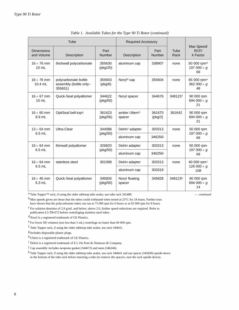
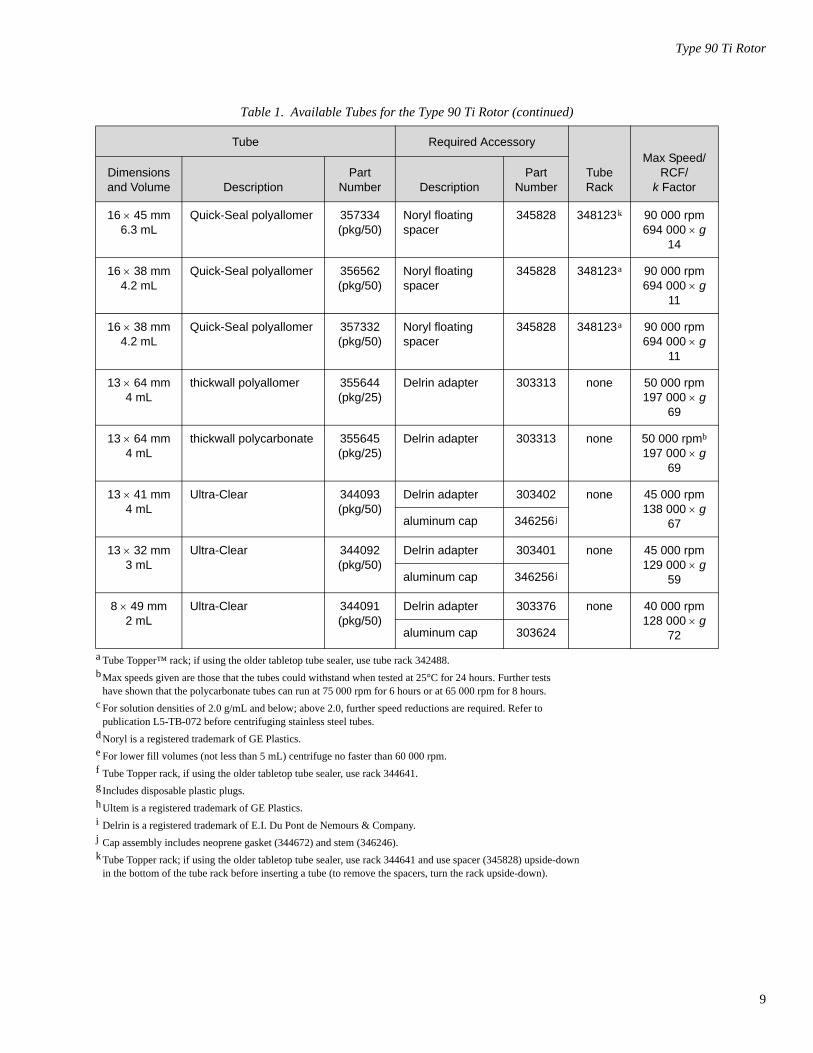
The Type 90 Ti rotor uses the tubes and bottles listed in Table 1. Be sure to use only those items listed, and to observe the maximum speed limits and fill volumes shown. (Maximum fill volume is the maximum amount that can be centrifuged in the container listed.) Refer to Appendix A in Rotors and Tubes for chemical compatibili-ties of tube, bottle, and accessory materials.
Table 1. Available Tubes for the Type 90 Ti Rotor. Use only the items listed here.
a Tube Topper™ rack; if using the older tabletop tube sealer, use tube rack 342488. — continuedb Max speeds given are those that the tubes could withstand when tested at 25°C for 24 hours. Further tests
have shown that the polycarbonate tubes can run at 75 000 rpm for 6 hours or at 65 000 rpm for 8 hours.c For solution densities of 2.0 g/mL and below; above 2.0, further speed reductions are required. Refer to
publication L5-TB-072 before centrifuging stainless steel tubes.d Noryl is a registered trademark of GE Plastics.e For lower fill volumes (not less than 5 mL) centrifuge no faster than 60 000 rpm.f Tube Topper rack, if using the older tabletop tube sealer, use rack 344641.g Includes disposable plastic plugs.h Ultem is a registered trademark of GE Plastics.i Delrin is a registered trademark of E.I. Du Pont de Nemours & Company.j Cap assembly includes neoprene gasket (344672) and stem (346246).k Tube Topper rack; if using the older tabletop tube sealer, use rack 344641 and use spacer (345828) upside-down
in the bottom of the tube rack before inserting a tube (to remove the spacers, turn the rack upside-down).
Tube Required Accessory
TubeRack
Max Speed/RCF/
k FactorDimensionsand Volume Description
PartNumber Description
PartNumber
16 × 76 mm13.5 mL
Quick-Seal®Ultra-Clear™
344322(pkg/50)
red aluminum spacer
342695 348123a 90 000 rpm694 000 × g
25
16 × 76 mm13.5 mL
Quick-Seal polyallomer 342413(pkg/50)
red aluminum spacer
342695 348123a 90 000 rpm694 000 × g
25
16 × 76 mm13.5 mL
Ultra-Clear 344085(pkg/50)
titanium cap (use the red silicone O-ring)
341968 none 80 000 rpm548 000 × g
32
16 × 76 mm13.5 mL
thinwall polyallomer 326814(pkg/50)
titanium cap (use the black Buna N O-ring)
341968 none 80 000 rpm548 000 × g
32
16 × 76 mm10 mL
thickwall polyallomer 355640(pkg/25)
aluminum cap 338907 none 30 000 rpm77 000 × g
190
7
8
Type 90 Ti Rotor
Table 1. Available Tubes for the Type 90 Ti Rotor (continued)
a Tube Topper™ rack; if using the older tabletop tube sealer, use tube rack 342488. — continuedb Max speeds given are those that the tubes could withstand when tested at 25°C for 24 hours. Further tests
have shown that the polycarbonate tubes can run at 75 000 rpm for 6 hours or at 65 000 rpm for 8 hours.c For solution densities of 2.0 g/mL and below; above 2.0, further speed reductions are required. Refer to
publication L5-TB-072 before centrifuging stainless steel tubes.d Noryl is a registered trademark of GE Plastics.e For lower fill volumes (not less than 5 mL) centrifuge no faster than 60 000 rpm.f Tube Topper rack, if using the older tabletop tube sealer, use rack 344641.g Includes disposable plastic plugs.h Ultem is a registered trademark of GE Plastics.i Delrin is a registered trademark of E.I. Du Pont de Nemours & Company.j Cap assembly includes neoprene gasket (344672) and stem (346246).k Tube Topper rack; if using the older tabletop tube sealer, use rack 344641 and use spacer (345828) upside-down
in the bottom of the tube rack before inserting a tube (to remove the spacers, turn the rack upside-down).
Tube Required Accessory
TubeRack
Max Speed/RCF/
k FactorDimensionsand Volume Description
PartNumber Description
PartNumber
16 × 76 mm10 mL
thickwall polycarbonate 355630(pkg/25)
aluminum cap 338907 none 50 000 rpmb
197 000 × g69
16 × 76 mm10.4 mL
polycarbonate bottle assembly (bottle only–355651)
355603(pkg/6)
Noryld cap 355604 none 65 000 rpme
362 000 × g48
16 × 67 mm10 mL
Quick-Seal polyallomer 344622(pkg/50)
Noryl spacer 344676 348123 f 90 000 rpm694 000 × g
21
16 × 60 mm8.9 mL
OptiSeal bell-topg 361623(pkg/56)
amber Ultemh spacer
361670(pkg/2)
361642 90 000 rpm694 000 × g
21
13 × 64 mm6.5 mL
Ultra-Clear 344088(pkg/50)
Delrin i adapter 303313 none 50 000 rpm197 000 × g
69aluminum cap 346256 j
16 × 64 mm6.5 mL
thinwall polyallomer 326820(pkg/50)
Delrin adapter 303313 none 50 000 rpm197 000 × g
69aluminum cap 346256 j
16 × 64 mm6.5 mL
stainless steel 301099 Delrin adapter 303313 none 40 000 rpmc
126 000 × g108aluminum cap 303319
16 × 45 mm6.3 mL
Quick-Seal polyallomer 345830(pkg/50)
Noryl floating spacer
345828 348123k 90 000 rpm694 000 × g
14
Type 90 Ti Rotor
Table 1. Available Tubes for the Type 90 Ti Rotor (continued)
a Tube Topper™ rack; if using the older tabletop tube sealer, use tube rack 342488.b Max speeds given are those that the tubes could withstand when tested at 25°C for 24 hours. Further tests
have shown that the polycarbonate tubes can run at 75 000 rpm for 6 hours or at 65 000 rpm for 8 hours.c For solution densities of 2.0 g/mL and below; above 2.0, further speed reductions are required. Refer to
publication L5-TB-072 before centrifuging stainless steel tubes.d Noryl is a registered trademark of GE Plastics.e For lower fill volumes (not less than 5 mL) centrifuge no faster than 60 000 rpm.f Tube Topper rack, if using the older tabletop tube sealer, use rack 344641.g Includes disposable plastic plugs.h Ultem is a registered trademark of GE Plastics.i Delrin is a registered trademark of E.I. Du Pont de Nemours & Company.j Cap assembly includes neoprene gasket (344672) and stem (346246).k Tube Topper rack; if using the older tabletop tube sealer, use rack 344641 and use spacer (345828) upside-down
in the bottom of the tube rack before inserting a tube (to remove the spacers, turn the rack upside-down).
Tube Required Accessory
TubeRack
Max Speed/RCF/
k FactorDimensionsand Volume Description
PartNumber Description
PartNumber
16 × 45 mm6.3 mL
Quick-Seal polyallomer 357334(pkg/50)
Noryl floating spacer
345828 348123k 90 000 rpm694 000 × g
14
16 × 38 mm4.2 mL
Quick-Seal polyallomer 356562(pkg/50)
Noryl floating spacer
345828 348123a 90 000 rpm694 000 × g
11
16 × 38 mm4.2 mL
Quick-Seal polyallomer 357332(pkg/50)
Noryl floating spacer
345828 348123a 90 000 rpm694 000 × g
11
13 × 64 mm4 mL
thickwall polyallomer 355644(pkg/25)
Delrin adapter 303313 none 50 000 rpm197 000 × g
69
13 × 64 mm4 mL
thickwall polycarbonate 355645(pkg/25)
Delrin adapter 303313 none 50 000 rpmb
197 000 × g69
13 × 41 mm4 mL
Ultra-Clear 344093(pkg/50)
Delrin adapter 303402 none 45 000 rpm138 000 × g
67aluminum cap 346256 j
13 × 32 mm3 mL
Ultra-Clear 344092(pkg/50)
Delrin adapter 303401 none 45 000 rpm129 000 × g
59aluminum cap 346256 j
8 × 49 mm2 mL
Ultra-Clear 344091(pkg/50)
Delrin adapter 303376 none 40 000 rpm128 000 × g
72aluminum cap 303624
9
10
Type 90 Ti Rotor
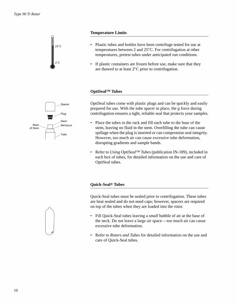
Temperature Limits
• Plastic tubes and bottles have been centrifuge tested for use at temperatures between 2 and 25°C. For centrifugation at other temperatures, pretest tubes under anticipated run conditions.
• If plastic containers are frozen before use, make sure that they are thawed to at least 2°C prior to centrifugation.
OptiSeal™ Tubes
OptiSeal tubes come with plastic plugs and can be quickly and easily prepared for use. With the tube spacer in place, the g force during centrifugation ensures a tight, reliable seal that protects your samples.
• Place the tubes in the rack and fill each tube to the base of the stem, leaving no fluid in the stem. Overfilling the tube can cause spillage when the plug is inserted or can compromise seal integrity. However, too much air can cause excessive tube deformation, disrupting gradients and sample bands.
• Refer to Using OptiSeal™ Tubes (publication IN-189), included in each box of tubes, for detailed information on the use and care of OptiSeal tubes.
Quick-Seal® Tubes
Quick-Seal tubes must be sealed prior to centrifugation. These tubes are heat sealed and do not need caps; however, spacers are required on top of the tubes when they are loaded into the rotor.
• Fill Quick-Seal tubes leaving a small bubble of air at the base of the neck. Do not leave a large air space—too much air can cause excessive tube deformation.
• Refer to Rotors and Tubes for detailed information on the use and care of Quick-Seal tubes.
Spacer
Plug
Tube
StemMeniscusBase
of Stem
Type 90 Ti Rotor
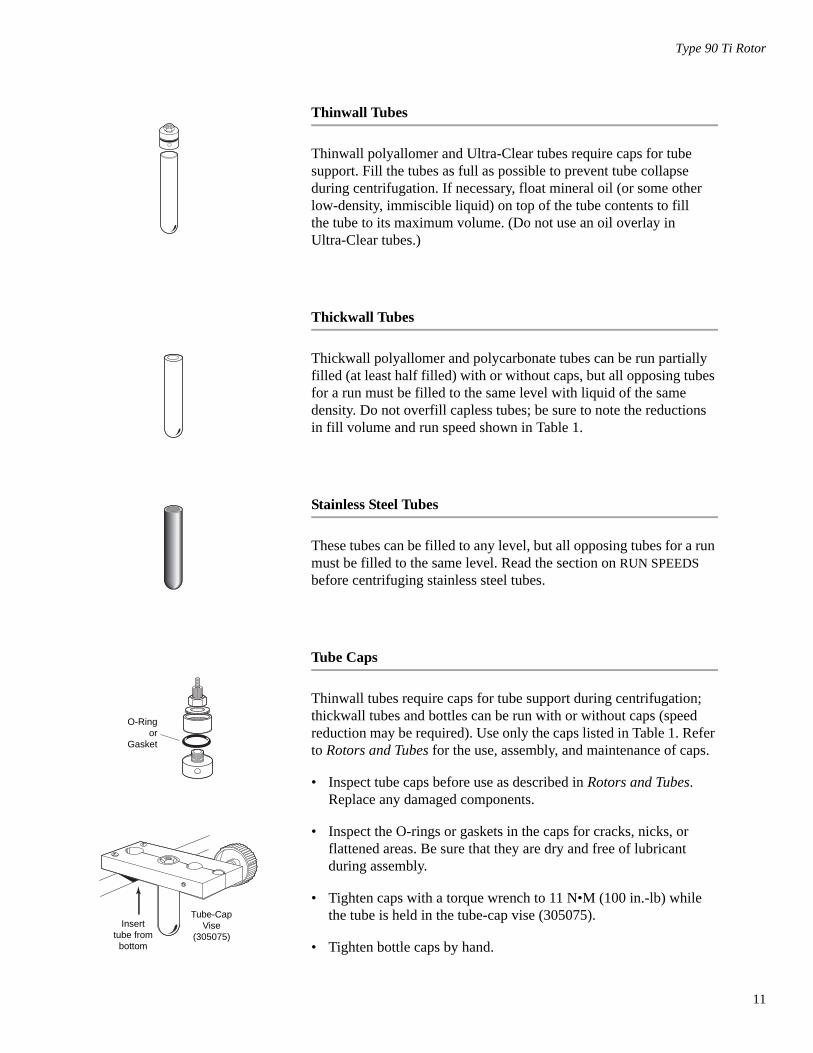
Thinwall Tubes
Thinwall polyallomer and Ultra-Clear tubes require caps for tube support. Fill the tubes as full as possible to prevent tube collapse during centrifugation. If necessary, float mineral oil (or some other low-density, immiscible liquid) on top of the tube contents to fill the tube to its maximum volume. (Do not use an oil overlay in Ultra-Clear tubes.)
Thickwall Tubes
Thickwall polyallomer and polycarbonate tubes can be run partially filled (at least half filled) with or without caps, but all opposing tubes for a run must be filled to the same level with liquid of the same density. Do not overfill capless tubes; be sure to note the reductions in fill volume and run speed shown in Table 1.
Stainless Steel Tubes
These tubes can be filled to any level, but all opposing tubes for a run must be filled to the same level. Read the section on RUN SPEEDS before centrifuging stainless steel tubes.
Tube Caps
Thinwall tubes require caps for tube support during centrifugation; thickwall tubes and bottles can be run with or without caps (speed reduction may be required). Use only the caps listed in Table 1. Refer to Rotors and Tubes for the use, assembly, and maintenance of caps.
• Inspect tube caps before use as described in Rotors and Tubes. Replace any damaged components.
• Inspect the O-rings or gaskets in the caps for cracks, nicks, or flattened areas. Be sure that they are dry and free of lubricant during assembly.
• Tighten caps with a torque wrench to 11 N•M (100 in.-lb) while the tube is held in the tube-cap vise (305075).
• Tighten bottle caps by hand.
O-Ringor
Gasket
Tube-CapVise
(305075)Insert
tube frombottom
11

12
Type 90 Ti Rotor
Polycarbonate Bottles
The polycarbonate bottles may be centrifuged completely filled, or partially filled (not less than half full). Again, all opposing containers for a run must be filled to the same level. Be sure to note the reduc-tions in run speed shown in Table 1 if bottles are partially filled.
RUN TIMES
The k factor of the rotor is a measure of the rotor’s pelleting effi-ciency. (Beckman Coulter has calculated the k factors for all of its preparative rotors at maximum rated speed and using full tubes.) The k factor is calculated from the formula:
(1)
where ω is the angular velocity of the rotor in radians per second (ω = 0.105 × rpm), rmax is the maximum radius, and rmin is the minimum radius.
After substitution:
(2)
Use the k factor in the following equation to estimate the run time t (in hours) required to pellet particles of known sedimentation coeffi-cient s (in Svedberg units, S).
(3)
Run times can be estimated for centrifugation at less than maximum speed by adjusting the k factor as follows:
(4)
TIME HR:MIN
krmax rmin⁄( )ln
ω 2------------------------------------- 1013
3600------------×=
k2.533 1011×( ) rmax r⁄ min( )ln
rpm2--------------------------------------------------------------------------=
t ks--=
kadj k 90 000actual run speed---------------------------------------⎝ ⎠
⎛ ⎞2
=
Type 90 Ti Rotor
Run times can also be estimated from data established in prior experi-ments using a different rotor if the k factor of the previous rotor is known. For any two rotors, a and b:
(5)
For more information on k factors see Use of k Factor for Estimating Run Times from Previously Established Run Conditions (publication DS-719).
RUN SPEEDS
The centrifugal force at a given radius in a rotor is a function of speed. Comparisons of forces between different rotors are made by comparing the rotors’ relative centrifugal fields (RCF). When rotational speed is adjusted so that identical samples are subjected to the same RCF in two different rotors, the samples are subjected to the same force. The RCF at a number of rotor speeds is provided in Table 2.
Do not select rotational speeds that exceed the limits in Table 1. In addition, speeds must be reduced under the following circumstances:
1. If nonprecipitating solutions more dense than 1.2 g/mL are centri-fuged in plastic tubes or bottles, the maximum allowable run speed must be reduced according to the following equation:
(6)
where ρ is the density of tube contents. This speed reduction will protect the rotor from excessive stresses due to the added tube load. Note, however, that the use of this formula may still produce maximum speeds that are higher than the limitations imposed by the use of certain tubes or adapters (see Table 1). In such cases, use the lower of the two speeds.
ta tb -----
ka kb ------=
SPEED RPM/RCF
reduced maximum speed = (90 000 rpm) 1.2 g/mLρ
----------------------
13

14
Type 90 Ti Rotor
Table 2. Relative Centrifugal Fields for the Type 90 Ti Rotor.Entries in this table are calculated from the formula
RCF = 1.12 r (RPM/100)2 and then rounded to three significant digits.
* Calculated for all Beckman Coulter preparative rotors as a measure of the rotor’s pelleting efficiencyin water at 20°C.
RotorSpeed(rpm)
Relative Centrifugal Field (× g)
kFactor*
At rmax(76.5 mm)
At rav(55.4 mm)
At rmin(34.2 mm)
90 00085 00080 00075 00070 000
694 000619 000548 000482 000420 000
503 000448 000397 000349 000304 000
310 000277 000245 000215 000188 000
2528323642
65 00060 00055 00050 000
362 000308 000259 000214 000
262 000223 000188 000155 000
162 000138 000116 00095 800
48576782
45 00040 00035 00030 000
174 000137 000105 00077 100
126 00099 30076 00055 800
77 60061 30046 90034 500
101127166227
RC
F (x
g)
rmax
rmin
rav
Relative Centrifugal Fields (RCF)for the Type 90 Ti Rotor
0
80 000
160 000
240 000
320 000
400 000
480 000
560 000
0 10 000 20 000 30 000 40 000 50 000 60 000
Speed (rpm)
640 000
720 000
70 000 80 000 90 000
Type 90 Ti Rotor
2. For centrifuging solutions of any density in stainless steel tubes and aluminum cap combinations, use the following formula to determine the allowable rotor speed based on the tube load:
(7)
where X = the weight in grams of the capped tube plus the liquid contents to be centrifuged.
In any case, the rotor speed when using this tube/cap combination must not exceed the limits in Table 1.
3. Further speed limits must be imposed when CsCl or other self-forming-gradient salts are centrifuged, as equation (6) or (7) does not predict concentration limits/speeds that are required to avoid precipitation of salt crystals. Solid CsCl has a density of4 g/mL, and if precipitated during centrifugation may cause cata-strophic rotor failure and instrument damage. Figures 2 and 3, together with the description and examples below, show how to reduce run speeds when using CsCl gradients.
SELECTING CsCl GRADIENTS
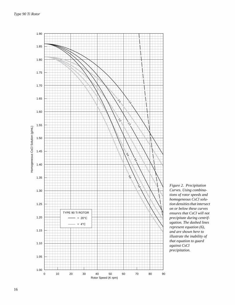
Precipitation during centrifugation would alter density distribution, and this would change the position of the sample bands. Curves in Figures 2 and 3 are provided up to the maximum rated speed of the rotor, but note also that tubes or bottles must never be centrifuged faster than the limits in Table 1.
➠ NOTEThe curves in Figures 2 and 3 are for solutions of CsCl salt dissolved in distilled water only. If other salts are present in significant concentra-tions, the overall CsCl concentration may need to be reduced.
Rotor speed is used to control the slope of a CsCl density gradient, and must be limited so that CsCl precipitation is avoided. Speed and density combinations that intersect on or below the curves in Figure 2 ensure that CsCl will not precipitate during centrifugation in the Type 90 Ti rotor. Curves are provided at two temperatures: 20°C (gray curves) and 4°C (black curves).
reduced maximum speed = (90 000 rpm) 46.2 gramsX
--------------------------
15
16
Type 90 Ti Rotor
1.15
1.20
0 10 20 30 40 50 60 70 80 90Rotor Speed (K rpm)
1.10
1.05
1.00
1.25
1.35
1.30
1.40
1.45
1.50
1.55
1.60
1.65
1.70
1.75
1.80
1.85
1.90H
omog
eneo
us C
sCl S
olut
ion
(g/m
L)
TYPE 90 Ti ROTOR
= 20°C
= 4°C
3/4
3/4
full
full1/4
1/4
1/2
1/2
Figure 2. Precipitation Curves. Using combina-tions of rotor speeds and homogeneous CsCl solu-tion densities that intersect on or below these curves ensures that CsCl will not precipitate during centrif-ugation. The dashed lines represent equation (6), and are shown here to illustrate the inability of that equation to guard against CsCl precipitation.
Type 90 Ti Rotor
1.15
1.20
34.2 46.1 55.2 63.0 76.5
1.10
1.05
1.00
1.25
1.35
1.30
1.40
1.45
1.50
1.55
1.60
1.65
1.70
1.75
1.80
1.85
1.90
Den
sity
(g/m
L)
Distance from Axis of Rotation (mm)rmin rmax
50 00
0 rpm
50 00
0 rpm
80 000 rpm
90 000 rpm
70 00
0 rpm
70 00
0 rpm
60 00
0 rpm
60 0
00 rp
m
TYPE 90 Ti ROTOR
= 20°C
= 4°C
90 00
0 rpm
80 0
00 rp
m
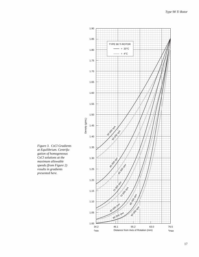
Figure 3. CsCl Gradients at Equilibrium. Centrifu-gation of homogeneous CsCl solutions at the maximum allowable speeds (from Figure 2) results in gradients presented here.
17
18
Type 90 Ti Rotor
The reference curves in Figure 3 show gradient distribution at equi-librium. Each curve in Figure 3 is within the density limits allowed for the Type 90 Ti rotor: each curve was generated for a single run speed using the maximum allowable homogeneous CsCl densities (one for each fill level) that avoid precipitation at that speed. (The gradients in Figure 3 can be generated from step or linear gradients, or from homogeneous solutions. But the total amount of CsCl in solu-tion must be equivalent to a homogeneous solution corresponding to the concentrations specified in Figure 2.) Figure 3 can also be used to approximate the banding positions of sample particles.
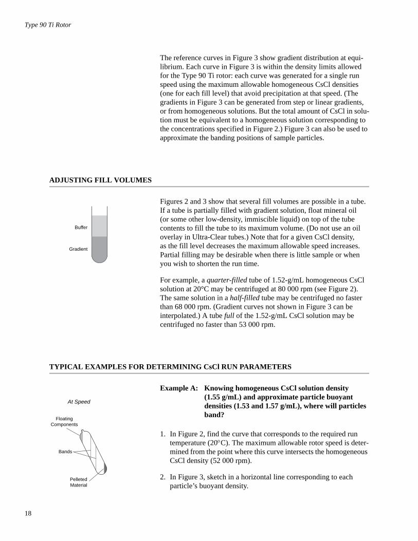
ADJUSTING FILL VOLUMES
Figures 2 and 3 show that several fill volumes are possible in a tube. If a tube is partially filled with gradient solution, float mineral oil (or some other low-density, immiscible liquid) on top of the tube contents to fill the tube to its maximum volume. (Do not use an oil overlay in Ultra-Clear tubes.) Note that for a given CsCl density, as the fill level decreases the maximum allowable speed increases. Partial filling may be desirable when there is little sample or when you wish to shorten the run time.
For example, a quarter-filled tube of 1.52-g/mL homogeneous CsCl solution at 20°C may be centrifuged at 80 000 rpm (see Figure 2). The same solution in a half-filled tube may be centrifuged no faster than 68 000 rpm. (Gradient curves not shown in Figure 3 can be interpolated.) A tube full of the 1.52-g/mL CsCl solution may be centrifuged no faster than 53 000 rpm.
TYPICAL EXAMPLES FOR DETERMINING CsCl RUN PARAMETERS
Example A: Knowing homogeneous CsCl solution density (1.55 g/mL) and approximate particle buoyant densities (1.53 and 1.57 g/mL), where will particles band?
1. In Figure 2, find the curve that corresponds to the required run temperature (20°C). The maximum allowable rotor speed is deter-mined from the point where this curve intersects the homogeneous CsCl density (52 000 rpm).
2. In Figure 3, sketch in a horizontal line corresponding to each particle’s buoyant density.
Buffer
Gradient
At Speed
Bands
FloatingComponents
PelletedMaterial
Type 90 Ti Rotor
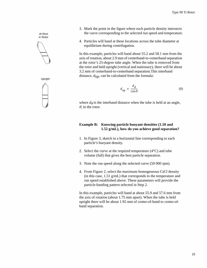
3. Mark the point in the figure where each particle density intersects the curve corresponding to the selected run speed and temperature.
4. Particles will band at these locations across the tube diameter at equilibrium during centrifugation.
In this example, particles will band about 55.2 and 58.1 mm from the axis of rotation, about 2.9 mm of centerband-to-centerband separation at the rotor’s 25-degree tube angle. When the tube is removed from the rotor and held upright (vertical and stationary), there will be about 3.2 mm of centerband-to-centerband separation.This interband distance, dup, can be calculated from the formula:
(8)
where dθ is the interband distance when the tube is held at an angle, θ, in the rotor.
Example B: Knowing particle buoyant densities (1.50 and 1.52 g/mL), how do you achieve good separation?
1. In Figure 3, sketch in a horizontal line corresponding to each particle’s buoyant density.
2. Select the curve at the required temperature (4°C) and tube volume (full) that gives the best particle separation.
3. Note the run speed along the selected curve (50 000 rpm).
4. From Figure 2, select the maximum homogeneous CsCl density (in this case, 1.51 g/mL) that corresponds to the temperature and run speed established above. These parameters will provide the particle-banding pattern selected in Step 2.
In this example, particles will band at about 55.9 and 57.6 mm from the axis of rotation (about 1.75 mm apart). When the tube is held upright there will be about 1.92 mm of center-of-band to center-of-band separation.
At Restin Rotor
Upright
dupdθ
θcos------------=
19
20
Type 90 Ti Rotor
CARE AND MAINTENANCE
MAINTENANCE
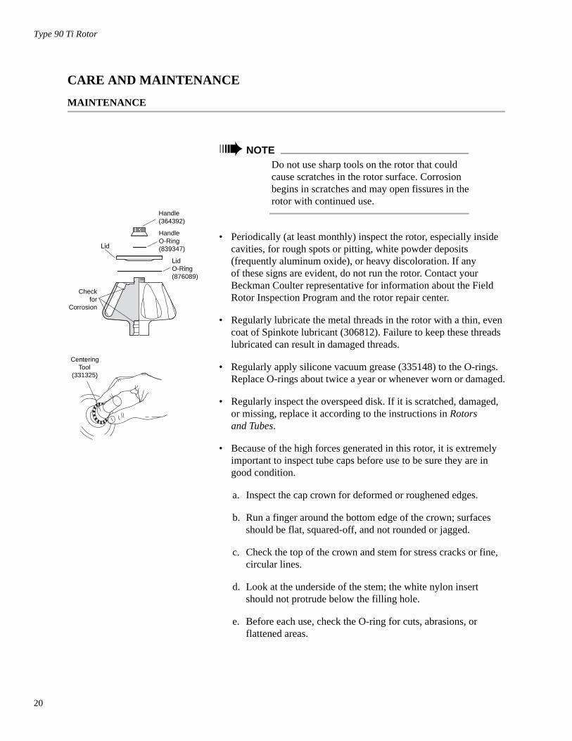
➠ NOTEDo not use sharp tools on the rotor that could cause scratches in the rotor surface. Corrosion begins in scratches and may open fissures in the rotor with continued use.
• Periodically (at least monthly) inspect the rotor, especially inside cavities, for rough spots or pitting, white powder deposits (frequently aluminum oxide), or heavy discoloration. If any of these signs are evident, do not run the rotor. Contact your Beckman Coulter representative for information about the Field Rotor Inspection Program and the rotor repair center.
• Regularly lubricate the metal threads in the rotor with a thin, even coat of Spinkote lubricant (306812). Failure to keep these threads lubricated can result in damaged threads.
• Regularly apply silicone vacuum grease (335148) to the O-rings. Replace O-rings about twice a year or whenever worn or damaged.
• Regularly inspect the overspeed disk. If it is scratched, damaged, or missing, replace it according to the instructions in Rotors and Tubes.
• Because of the high forces generated in this rotor, it is extremely important to inspect tube caps before use to be sure they are in good condition.
a. Inspect the cap crown for deformed or roughened edges.
b. Run a finger around the bottom edge of the crown; surfaces should be flat, squared-off, and not rounded or jagged.
c. Check the top of the crown and stem for stress cracks or fine, circular lines.
d. Look at the underside of the stem; the white nylon insert should not protrude below the filling hole.
e. Before each use, check the O-ring for cuts, abrasions, or flattened areas.
Handle(364392)
Lid
HandleO-Ring(839347)
LidO-Ring(876089)
Checkfor
Corrosion
CenteringTool
(331325)
Type 90 Ti Rotor
Discard and replace any damaged component. Refer to Rotors and Tubes for detailed information about tube cap inspection and maintenance.
Refer to the chemical resistances table in Appendix A of Rotors and Tubes for chemical compatibilities of rotor and accessory materials. Your Beckman Coulter representative provides contact with the Field Rotor Inspection Program and the rotor repair center.
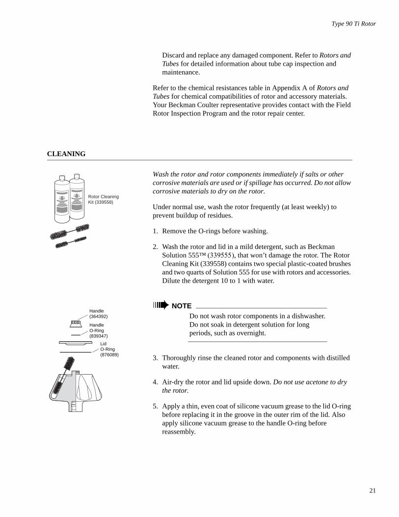
CLEANING
Wash the rotor and rotor components immediately if salts or other corrosive materials are used or if spillage has occurred. Do not allow corrosive materials to dry on the rotor.
Under normal use, wash the rotor frequently (at least weekly) to prevent buildup of residues.
1. Remove the O-rings before washing.
2. Wash the rotor and lid in a mild detergent, such as Beckman Solution 555™ (339555), that won’t damage the rotor. The Rotor Cleaning Kit (339558) contains two special plastic-coated brushes and two quarts of Solution 555 for use with rotors and accessories. Dilute the detergent 10 to 1 with water.
➠ NOTEDo not wash rotor components in a dishwasher. Do not soak in detergent solution for long periods, such as overnight.
3. Thoroughly rinse the cleaned rotor and components with distilled water.
4. Air-dry the rotor and lid upside down. Do not use acetone to dry the rotor.
5. Apply a thin, even coat of silicone vacuum grease to the lid O-ring before replacing it in the groove in the outer rim of the lid. Also apply silicone vacuum grease to the handle O-ring before reassembly.
Rotor CleaningKit (339558)
Handle(364392)
HandleO-Ring(839347)
LidO-Ring(876089)
21

22
Type 90 Ti Rotor
Clean metal threads every 6 months, or as necessary. Use a brush and concentrated Solution 555. Rinse and dry thoroughly, then lubricate lightly but evenly with Spinkote to coat all threads.
Periodically remove the O-rings and wipe clean as necessary. Clean the O-ring grooves with a cotton-tipped swab. Reapply a light film of silicone vacuum grease.
DECONTAMINATION
If the rotor (and/or accessories) becomes contaminated with radioac-tive material, it should be decontaminated using a solution that will not damage the anodized surfaces. Beckman Coulter has tested a number of solutions and found two that do not harm anodized aluminum: RadCon Surface Spray or IsoClean Solution (for soaking),1 and Radiacwash.2
➠ NOTEIsoClean can cause fading of colored anodized surfaces. Use it only when necessary and remove it promptly from surfaces.
While Beckman Coulter has tested these methods and found that they do not damage components, no guarantee of decontamination is expressed or implied. Consult your laboratory safety officer regarding the proper decontamination methods to use.
If the rotor or other components are contaminated with toxic or patho-genic materials, follow appropriate decontamination procedures as outlined by your laboratory safety officer.
1 In U.S., contact Nuclear Associates (New York); in Eastern Europe and Commonwealth States, contact Victoreen GmbH (Munich); in South Pacific, contact Gammasonics Pty. Ltd. (Australia); in Japan, contact Toyo Medic Co. Ltd. (Tokyo).
2 In U.S., contact Biodex Medical Systems (Shirley, New York); internationally, contact the U.S. office to find the dealer closest to you.
Type 90 Ti Rotor
STERILIZATION AND DISINFECTION
• The rotor and all rotor components can be autoclaved at 121°C for up to an hour. Remove the lid from the rotor and place the rotor, lid, and spacers in the autoclave upside down.
• Ethanol (70%)3 or hydrogen peroxide (6%) may be used on all rotor components, including those made of plastic. Bleach (sodium hypochlorite) may be used, but may cause discoloration of anod-ized surfaces. Use the minimum immersion time for each solution, per laboratory standards.
While Beckman Coulter has tested these methods and found that they do not damage the rotor or components, no guarantee of sterility or disinfection is expressed or implied. When sterilization or disinfec-tion is a concern, consult your laboratory safety officer regarding proper methods to use.
Refer to publication IN-192, included in each box of tubes or bottles, for tube and bottle sterilization and disinfection procedures. Quick-Seal and thinwall open-top tubes are disposable and should be discarded after a single use.
STORAGE
When the rotor is not in use, store it in a dry environment (not in the instrument) with the lid removed to allow air circulation so moisture will not collect in the tube cavities.
3 Flammability hazard. Do not use in or near operating centrifuges.
23
24
Type 90 Ti Rotor
RETURNING A ROTOR
Before returning a rotor or accessory for any reason, prior permission (a Returned Goods Authorization form) must be obtained from Beckman Coulter, Inc. This RGA form may be obtained from your local Beckman Coulter sales office, and should contain the following information:
• serial number
• history of use (approximate frequency of use),
• reason for the return,
• original purchase order number, billing number, and shipping number, if possible,
• name and phone number of the person to be notified upon receipt of the rotor or accessory at the factory, and,
• name and phone number of the person to be notified about repair costs, etc.
To protect our personnel, it is the customer’s responsibility to ensure that all parts are free from pathogens and/or radioactivity. Steriliza-tion and decontamination must be done before returning the parts. Smaller items (such as tubes, bottles, etc.) should be enclosed in a sealed plastic bag.
All parts must be accompanied by a note, plainly visible on the out-side of the box or bag, stating that they are safe to handle and that they are not contaminated with pathogens or radioactivity. Failure to attach this notification will result in return or disposal of the items without review of the reported problem.
Use the address label printed on the RGA form when mailing the rotor and/or accessories.
Customers located outside the United States should contact their local Beckman Coulter office.
RGA
Type 90 Ti Rotor
SUPPLY LIST
➠ NOTEPublications referenced in this manual can be obtained by calling Beckman Coulter at 1-800-742-2345 in the United States, or by contacting your local Beckman Coulter office.
See the Beckman Coulter Ultracentrifuge Rotors, Tubes, & Accesso-ries Catalog (BR-8101, available at www.beckmancoulter.com) for detailed information on ordering parts and supplies or contact Beckman Coulter sales (1-800-742-2345 in the United States; world-wide offices are listed on the back cover of this manual). For your convenience, a partial list is given below.
REPLACEMENT ROTOR PARTS
Type 90 Ti rotor assembly. . . . . . . . . . . . . . . . . . . . . . . . . . . . . . . . . 355530Rotor lid. . . . . . . . . . . . . . . . . . . . . . . . . . . . . . . . . . . . . . . . . . . . . . . 355528Rotor handle . . . . . . . . . . . . . . . . . . . . . . . . . . . . . . . . . . . . . . . . . . . 355529O-ring (large). . . . . . . . . . . . . . . . . . . . . . . . . . . . . . . . . . . . . . . . . . . 876089O-ring (small) . . . . . . . . . . . . . . . . . . . . . . . . . . . . . . . . . . . . . . . . . . 839347Overspeed disk (90 000 rpm) . . . . . . . . . . . . . . . . . . . . . . . . . . . . . . 355539
OTHER
Tubes, bottles, and accessories . . . . . . . . . . . . . . . . . . . . . . . . . . see Table 1OptiSeal tube rack assembly . . . . . . . . . . . . . . . . . . . . . . . . . . . . . . . 361642Quick-Seal Cordless Tube Topper kit, 60 Hz . . . . . . . . . . . . . . . . . . 358312Quick-Seal Cordless Tube Topper kit, 50 Hz (Europe) . . . . . . . . . . 358313Quick-Seal Cordless Tube Topper kit, 50 Hz (Great Britain) . . . . . . 358314Quick-Seal Cordless Tube Topper kit, 50 Hz (Australia) . . . . . . . . . 358315Quick-Seal Cordless Tube Topper kit, 50 Hz (Canada) . . . . . . . . . . 367803Tube Topper rack . . . . . . . . . . . . . . . . . . . . . . . . . . . . . . . . . . . . . . . 348123Tool kit for aluminum caps . . . . . . . . . . . . . . . . . . . . . . . . . . . . . . . . 331202
includes:Torque wrench. . . . . . . . . . . . . . . . . . . . . . . . . . . . . . . . . . . . . . . . 858121Socket adapter . . . . . . . . . . . . . . . . . . . . . . . . . . . . . . . . . . . . . . . 858122Socket for 11-mm hex nuts . . . . . . . . . . . . . . . . . . . . . . . . . . . . . . 870432
Tube removal tool . . . . . . . . . . . . . . . . . . . . . . . . . . . . . . . . . . . . . . . 301875Hex driver (for 11-mm cap nuts on stainless steel tubes) . . . . . . . . . 841883
25

26
Type 90 Ti Rotor
Handle tool . . . . . . . . . . . . . . . . . . . . . . . . . . . . . . . . . . . . . . . . . . . . 356959Floating spacer removal tool . . . . . . . . . . . . . . . . . . . . . . . . . . . . . . . 338765Tube-cap vise . . . . . . . . . . . . . . . . . . . . . . . . . . . . . . . . . . . . . . . . . . 305075Tube removal tool (Quick-Seal and OptiSeal tubes). . . . . . . . . . . . . 361668Spinkote lubricant (2 oz) . . . . . . . . . . . . . . . . . . . . . . . . . . . . . . . . . . 306812Silicone vacuum grease (1 oz) . . . . . . . . . . . . . . . . . . . . . . . . . . . . . 335148Rotor Cleaning Kit . . . . . . . . . . . . . . . . . . . . . . . . . . . . . . . . . . . . . . 339558Beckman Solution 555 (1 qt) . . . . . . . . . . . . . . . . . . . . . . . . . . . . . . 339555Rotor cleaning brush . . . . . . . . . . . . . . . . . . . . . . . . . . . . . . . . . . . . . 339379Centering tool (for replacing overspeed disk). . . . . . . . . . . . . . . . . . 331325
ULTRACENTRIFUGE ROTOR WARRANTY
All Beckman Coulter ultracentrifuge Fixed Angle, Vertical Tube,Near Vertical Tube, Swinging Bucket, and Airfuge rotors arewarranted against defects in materials or workmanship for the timeperiods indicated below, subject to the Warranty Conditions statedbelow.
Preparative Ultracentrifuge Rotors . . . . . . 5 years — No Proration
Analytical Ultracentrifuge Rotors. . . . . . . 5 years — No Proration
ML and TL Series UltracentrifugeRotors . . . . . . . . . . . . . . . . . . . . . . . . . . 5 years — No Proration
Airfuge Ultracentrifuge Rotors . . . . . . . . . 1 year — No Proration
For Zonal, Continuous Flow, Component Test, and Rock Coreultracentrifuge rotors, see separate warranty.
Warranty Conditions (as applicable)
1) This warranty is valid for the time periods indicated above fromthe date of shipment to the original Buyer by Beckman Coulteror an authorized Beckman Coulter representative.
2) This warranty extends only to the original Buyer and may notbe assigned or extended to a third person without writtenconsent of Beckman Coulter.
3) This warranty covers the Beckman Coulter Centrifuge Systemsonly (including but not limited to the centrifuge, rotor, andaccessories) and Beckman Coulter shall not be liable fordamage to or loss of the user’s sample, non-Beckman Coultertubes, adapters, or other rotor contents.
4) This warranty is void if the Beckman Coulter Centrifuge Sys-tem is determined by Beckman Coulter to have been operatedor maintained in a manner contrary to the instructions in theoperator’s manual(s) for the Beckman Coulter CentrifugeSystem components in use. This includes but is not limited tooperator misuse, abuse, or negligence regarding indicatedmaintenance procedures, centrifuge and rotor classificationrequirements, proper speed reduction for the high density ofcertain fluids, tubes, and tube caps, speed reduction for precipi-tating gradient materials, and speed reduction for high-tempera-ture operation.
5) Rotor bucket sets purchased concurrently with or subsequent tothe purchase of a Swinging Bucket Rotor are warranted only fora term co-extensive with that of the rotor for which the bucketsets are purchased.
6) This warranty does not cover the failure of a Beckman Coulterrotor in a centrifuge not of Beckman Coulter manufacture, or ifthe rotor is used in a Beckman Coulter centrifuge that has beenmodified without the written permission of Beckman Coulter,or is used with carriers, buckets, belts, or other devices not ofBeckman Coulter manufacture.
7) Rotor parts subject to wear, including but not limited to rotorO-rings, VTi, NVT™, TLV, MLN, and TLN rotor tube cavityplugs and gaskets, tubing, tools, optical overspeed disks, bear-ings, seals, and lubrication are excluded from this warranty andshould be frequently inspected and replaced if they becomeworn or damaged.
8) Keeping a rotor log is not mandatory, but may be desirable formaintenance of good laboratory practices.
Repair and Replacement Policies
1) If a Beckman Coulter rotor is determined by Beckman Coulterto be defective, Beckman Coulter will repair or replace it,subject to the Warranty Conditions. A replacement rotor will bewarranted for the time remaining on the original rotor’swarranty.
2) If a Beckman Coulter centrifuge is damaged due to a failure ofa rotor covered by this warranty, Beckman Coulter will supplyfree of charge (i) all centrifuge parts required for repair (exceptthe drive unit, which will be replaced at the then current priceless a credit determined by the total number of revolutions oryears completed, provided that such a unit was manufactured orrebuilt by Beckman Coulter), and (ii) if the centrifuge is cur-rently covered by a Beckman Coulter warranty or Full ServiceAgreement, all labor necessary for repair of the centrifuge.
3) If a Beckman Coulter rotor covered by this warranty is dam-aged due to a malfunction of a Beckman Coulter ultracentrifugecovered by an Ultracentrifuge System Service Agreement,Beckman Coulter will repair or replace the rotor free of charge.
4) If a Beckman Coulter rotor covered by this warranty isdamaged due to a failure of a Beckman Coulter tube, bottle,tube cap, spacer, or adapter, covered under the Conditions ofthis Warranty, Beckman Coulter will repair or replace the rotorand repair the instrument as per the conditions in policy point(2) above, and the replacement policy.
5) Damage to a Beckman Coulter rotor or instrument due to thefailure or malfunction of a non-Beckman Coulter tube, bottle,tube cap, spacer, or adapter is not covered under this warranty,although Beckman Coulter will assist in seeking compensationunder the manufacturer’s warranty.
Disclaimer
IT IS EXPRESSLY AGREED THAT THE ABOVE WARRANTYSHALL BE IN LIEU OF ALL WARRANTIES OF FITNESS ANDOF THE WARRANTY OF MERCHANTABILITY ANDBECKMAN COULTER, INC. SHALL HAVE NO LIABILITYFOR SPECIAL OR CONSEQUENTIAL DAMAGES OF ANYKIND WHATSOEVER ARISING OUT OF THE MANUFAC-TURE, USE, SALE, HANDLING, REPAIR, MAINTENANCE,OR REPLACEMENT OF THE PRODUCT.
Factory Rotor Inspection ServiceBeckman Coulter, Inc., will provide free mechanical andmetallurgical inspection in Indianapolis, Indiana, USA, of anyBeckman Coulter rotor at the request of the user. (Shipping chargesto Beckman Coulter are the responsibility of the user.) Rotors willbe inspected in the user’s laboratory if the centrifuge in which theyare used is covered by an appropriate Beckman Coulter ServiceAgreement. Contact your local Beckman Coulter office for detailsof service coverage or cost.
Before shipping, contact the nearest Beckman Coulter Sales andService office and request a Returned Goods Authorization (RGA)form and packaging instructions. Please include the complete rotorassembly, with buckets, lid, handle, tube cavity caps, etc. ASIGNED STATEMENT THAT THE ROTOR AND ACCESSO-RIES ARE NON-RADIOACTIVE, NON-PATHOGENIC, NON-TOXIC, AND OTHERWISE SAFE TO SHIP AND HANDLE ISREQUIRED.
Beckman Coulter, Inc. • 250 S. Kraemer Blvd. • Brea, California 92821Sales and Service: 1-800-742-2345 • Internet: www.beckmancoulter.com
©2009 Beckman Coulter, Inc.All rights reserved


![Rotor 90 [.pdf 15.7 Mb]](https://static.fdocuments.us/doc/165x107/586ce1f41a28abf6518bbde9/rotor-90-pdf-157-mb.jpg)