TYP 9180 - J and B Group Technologies Official Website · TYP 9180 MODBUS PROTOCOL COMPATIBLE ......
95
MULTIFUNCTION DIGITAL PANEL INSTRUMENT TYP 9180 MODBUS PROTOCOL COMPATIBLE INSTRUCTIONS MANUAL Valid for instruments from s/n 133507 CODE: 30727119 EDI TI ON: 30-10-2006
Transcript of TYP 9180 - J and B Group Technologies Official Website · TYP 9180 MODBUS PROTOCOL COMPATIBLE ......

51
Menu 23 -rAtE-. Select reading rate. The reading rate determines the rate at which the display is updated. This parameter affects the display, the setpoints, the analog output and the BCD output. Available values are 16, 4 and 1 per second. Press
to select desired rate. Lower levels produce slower display responses to signal changes. The 16 readings/s option will update the display at the rythm of the signal conversion. For temperature configurations the effective rate is half the selected number of readings/s.
ENTER Validate the choice and return to the "-Pro-" stage. ESC Cancel the programming and go to the "-Pro-" stage.
MULTIFUNCTION
DIGITAL PANEL INSTRUMENT
TYP 9180 MODBUS PROTOCOL COMPATIBLE
INSTRUCTIONS MANUAL
Valid for instruments from s/n 133507
[51.1] Reading Rate
TARE
RESET
LIMIT
MAX/MIN
DATA
ESC
ENTER
M
A X
M I N
HOLD
TARE
1
2
3
4
C
OD
E: 3
0727
119
ED
ITIO
N:
30-1
0-20
06

52
If the display reading is unstable due to small signal variations or noise, the use of digital filters may help to reduce these effects and eliminate display jittering. The filter-E parameter only appears for process, load cell or potentiometer inputs.
The figure 52.1 represents the access level to menu 25 -FILt-. At this stage, you can use one of the following keys:
ENTER To enter the first step of the menu. To skip this menu and pass to the menu 26 -round.
ESC To cancel this routine and return to the "-Pro-" stage.
Menu 25 FILt-P. Set filter P level. The P filter acts as a delay on the display response to signal variations produced at the input. The effect of incrementing this filter level results in a softer response of the display to the input variations. Select filter level from 0 (filter disabled) to 9 using the
key.
ENTER Validate changes and advance to the next step. ESC Cancel this routine and return to the "-Pro-" stage.
Menu 25 FILt-E. Set filter E level. The E filter cuts off input variations exceeding from the limits of a moving band. This band becomes more selective as the filter level is increased. Select filter level from 0 (filter disabled) to 9 using the key.
ENTER Validate changes and advance to the next step. ESC Cancel this routine and return to the "-Pro-" stage.
10. DECLARATION OF CONFORMITY
Manufacturer : burster präzisionmeßtechnik gmbh &
co kg
Address : burster präzisionmeßtechnik gmbh & co kg talstr. 1-5
D-76593
Declares, that the product :
Description : Digital panel multifunction meter
Model : TYP 9180
Conforms with the directives : EMC 89/336/CEE LVD 73/23/CEE
Applicable Standars : EN50081-1 Generic emission EN55022/CISPR22 Class B
Applicable Standars : EN50082-1 Generic immunity IEC1000-4-2 Level 3 Criteria B
Air Discharge 8kV Contact Discharge 6kV
IEC1000-4-3 Level 2 Criteria A 3V/m 80..1000MHz
IEC1000-4-4 Level 2 Criteria B 1kV Power Lines 0.5kV Signal Lines
Applicable Standars : EN61010-1 Generic Safety IEC1010-1 Installation Category II
Transient Voltages <2.5kV Pollution Degree 2 Conductive pollution excluded Insulation Type Enclosure : Double Inputs/Outputs : Basic
Date: 20 January 2004 Signed: José M. Edo Position: Technical Manager
Menu 25 - DIGITAL FILTERS
[52.1] Access to the Menu
TARE
RESET
LIMIT
MAX/MIN
DATA
ESC
ENTER
M
A X
M I N
HOLD
TARE
1
2
3
4
[52.2] Filter-P Level
TARE
RESET
LIMIT
MAX/MIN
DATA
ESC
ENTER
M
A X
M I N
HOLD
TARE
1
2
3
4
[52.3] Filter-E Level
TARE
RESET
LIMIT
MAX/MIN
DATA
ESC
ENTER
M
A X
M I N
HOLD
TARE
1
2
3
4

53
3
Menu 25 AVErAG. Program nº of readings to average. This value represents the number of readings that are summed up together and averaged before the display is updated. Use the
(change value) and
(change digit) keys to program the desired value from 1 to 200.
ENTER Validate all changes in this menu and return to the -Pro- stage. ESC Exit this step and return to the -Pro- stage.
INTRODUCTION TO THE SERIES TYP
9180
This catalogue does not constitute a formal agreement. All information given in this manual is subject to
change without notice.
The SERIES TYP9180 brings a new phylosophy in digital panel instrumentation which is expressed by multipurpose, modular-concept devices providing a rich array of basic functions and advanced capabilities.
With a fully MODULAR DESIGN, it is possible to implement a wide variety of applications by only adding the adequate options.
Intelligence within allows the meter to recognize the options installed and ask for the necessary parameters to properly function within desired margins. The basic instrument without output options omits these data in the program routines.
The instrument's CALIBRATION is made at the factory eliminating the need for adjustment potentiometers. Any circuit or option that may need any adjust incorporates a memory where calibration parameters are stored, making it possible the optional cards be totally interchangeable without need of any subsequent adjust.
Custom CONFIGURATION for specific applications can be made quickly and easily through five front panel keys, following structured choice menus aided by display prompts at each programming step.
Other features of the TYP9180 family include :
CONNECTIONS via plug-in terminal blocks without screws and CLEMP-WAGO clips cable retention system.
DIMENSIONS 96x48x120 mm DIN 43700
CASE MATERIAL UL-94 V0-rated polycarbonate.
PANEL INSTALLATION by means of single part fingertip without screws.
To guarantee the meter's technical specifications, it is advised to check its calibration at periodical intervals according to the ISO9001 standards for the particular application operating criteria. Calibration should be perfomed at the factory or in a qualified laboratory.
[53.1] Average Filter
TARE
RESET
LIMIT
MAX/MIN
DATA
ESC
ENTER
M
A X
M I N
HOLD
TARE
1
2
3
4
54
4
This menu allows selection among six levels of display rounding. When resolution is not critical, a rounding increment other than 1 may help stabilize the display.
The figure 54.1 shows the indication corresponding to the access to the round menu. Press one of the following keys:
ENTER To get access to this menu. To skip this menu and pass to the menu 27 -VoL.
ESC To cancel this menu and return to the "-Pro-" stage.
Menu 26 -round. Select rounding increment. Press repeatedly the
key to scroll through available options for the round filter ["001" = no rounding, "005" = round to 5 counts, "010" = round to 10 counts, "020" = round to 20 counts, "050" = round to 50 counts or "100" = round to 100 counts].
ENTER Validate changes and return to the "-Pro-" stage. ESC Exit this step and return to the "-Pro-" stage.
DIGITAL PANEL INSTRUMENT
MODEL TYP 9180
Menu 25
- ROUND (process, load cell and potentiometer)
[54.1] Access to the menu
TARE
RESET
LIMIT
MAX/MIN
DATA
ESC
ENTER
M
A X
M I N
HOLD
TARE
1
2
3
4
[54.2] Round programming
TARE
RESET
LIMIT
MAX/MIN
DATA
ESC
ENTER
M
A X
M I N
HOLD
TARE
1
2
3
4
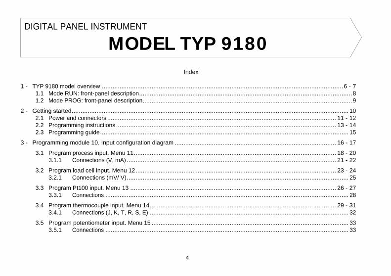
Index
1 - TYP 9180 model overview ........................................................................................................................................6 - 7 1.1 Mode RUN: front-panel description........................................................................................................................8 1.2 Mode PROG: front-panel description......................................................................................................................9
2 - Getting started............................................................................................................................................................ 10 2.1 Power and connectors ................................................................................................................................. 11 - 12 2.2 Programming instructions ............................................................................................................................ 13 - 14 2.3 Programming guide............................................................................................................................................ 15
3 - Programming module 10. Input configuration diagram ........................................................................................... 16 - 17
3.1 Program process input. Menu 11.................................................................................................................. 18 - 20 3.1.1 Connections (V, mA) ...................................................................................................................... 21 - 22
3.2 Program load cell input. Menu 12................................................................................................................. 23 - 24 3.2.1 Connections (mV/ V)............................................................................................................................. 25
3.3 Program Pt100 input. Menu 13 .................................................................................................................... 26 - 27 3.3.1 Connections ......................................................................................................................................... 28
3.4 Program thermocouple input. Menu 14......................................................................................................... 29 - 31 3.4.1 Connections (J, K, T, R, S, E) ................................................................................................................ 32
3.5 Program potentiometer input. Menu 15 ............................................................................................................... 33 3.5.1 Connections ......................................................................................................................................... 33

55
5
DIGITAL PANEL INSTRUMENT
MODEL TYP 9180 4 - Programming module 20. Display configuration diagram.........................................................................................34 - 35
4.1 Scaling. Menus 21 and 22 ............................................................................................................................36 - 45 4.2 Integrator. Menu 23 ....................................................................................................................................46 - 48 4.3 Display options, Filters and Round.......................................................................................................................49
4.3.1 Display options. Menu 24......................................................................................................................50- 51 4.3.2 Filters. Menu 25 ..................................................................................................................................52 - 53 4.3.3 Round. Menu 26.........................................................................................................................................54
4.4 Automatic volume calculation. Menu 27 ........................................................................................................55 - 58
5 - Front-panel functions and remote inputs 5.1 Front-panel functions...................................................................................................................................59 - 60 5.2 Remote inputs....................................................................................................................................................61
5.2.1 Table of remote input logic functions....................................................................................................62 - 64 5.2.2 Program remote input logic functions ..........................................................................................................65
6 - Programming parameters lockout .................................................................................................................................66 6.1 Lockout routine ..................................................................................................................................................67
7 - Output options .....................................................................................................................................................68 - 69
8 - Technical specifications.........................................................................................................................................70 - 71 8.1 Dimensions and mounting...................................................................................................................................72
9 - Warranty ....................................................................................................................................................................74
10 - Declaration of conformity...............................................................................................................................................2
ANNEXES. Index ................................................................................................................................................................78
4.4. Display Volume based on Pressure
There are several methods to calculate the volume of a fluid in a tank. If a pressure sensor is placed in the bottom of the tank, the display may be scaled to convert the sensor's pressures into liquid height.
The TYP 9180 provides different approaches to calculate liquid volume.
1. For some special regular tank shapes, if you know the mathematical relationship between pressure and volume, it will only be necessary to scale the display by two points. For example, for a cylindric vertical tank, volume is the product of the cylinder base area and the liquid height.
2. If the tank is irregularly shaped, you can use the linearization feature to readout volume utilizando el método teach y linealización por tramos. The method consists of filling the tank with known amounts of liquid, teach the input and enter the volume at each of the selected points over the height of the tank. The more the number of points used, the more accurate the measurement will be.
3. A third method that offers the instrument to extract volume is to set the automatic volume calculation function. This function can be used when the tank's shape correspond to one of the figures represented at right.
Automatic Volume Calculation
The instrument has most common tank geometry functions pre-programmed to calculate volume; spherical, horizontal cylinder, horizontal cylinder with spherical ends and conical bottom vertical cylinder. The user only has to enter the tank dimensions as requested in the program routine.
D1
D1
D1
L1
L1
Typ 1 - Sphere
Typ 2 - Cylinder
Typ 3 - Sphere+Cylinder
Typ 4 - Silo
L2
L3
L1
D1
D2
D3
L2
L1
D1
D2
L1
D1
D2
L3
D3

56
6
ANALOG OUTPUT
OPTION
BCD PARALLEL
OUTPUT OPTION
MULTI-INPUT CARD
A/D CONVERTER
CIRCUIT
RS232C/ RS485 OUTPUT OPTION
RELAY/ OPTO OUTPUT OPTION
POWER FILTER CIRCUIT
CASE WITH FIXING CLIPS
MAIN CIRCUIT
FRONT COVER
Programming Procedure to Readout Volume
When using this method to display volume, a pressure sensor must be placed at the bottom of the tank to drive a signal proportional to fluid level.
The first scaling phase is to convert the input signal to display height in meters. The height measurement is subsequently used to calculate volume.
The relation between pressure and height is linear, so two scaling points are enough to define the scale.
The decimal point position must be chosen so that the display values are expressed in meters, for example, if the fluid level on top scale is 1.5m, suitable programmings would be 0001.5, 001.50, 01.500 or 1.5000 depending on desired resolution.
Once the signal is scaled to measure level in meters, the second phase is to activate the option VOL to display volume. This option is enabled by selecting one of the available tank shapes (see figure). After this, you must enter the diameter and length of the tank in meters, and finally set the decimal point of the display, which is independent from the decimal point programmed in the scaling procedure.
Volume is expressed in whole liters despite of the point position.
-VoL-
27
no
SHAPE
27
tYP 1
SHAPE
27
tYP 2
SHAPE
27
tYP 3
SHAPE
27
tYP 4
SHAPE
27
02.000
dIAM-1
27
00000.
dIAM-1
27
02.000
dIAM-1
27
06.000
LEn-1
27
00000.
LEn-1
27
02.000
dIAM-1
27
06.000
LEn-1
27
00000.
LEn-1
27
02.000
dIAM-1
27
06.000
LEn-1
27
03.000
dIAM-2
27
00.000
LEn-2
27
03.000
dIAM-3
27
01.000
LEn-3
27
00000.
LEn-3
27
Programming Diagram
DISPLAY AND
KEYBOARD MODULE

57
7
This menu appears exclusively for process and potentiometer configurations. I t is not possible to enable this option if the integrator is active (menu 23) . The automatic volume calculation facility can be only used when the tank's shape is one of the pre-programmed shapes shown in page 55.
The figure 57.1, shows the indication "27 -VoL-" corresponding to the input stage of the automatic volume calculation menu. Use one of the following keys:
ENTER To get acces to this menu. To pass to the Pasar al Submenú 21 - SCAL.
ESC To cancel the programming and return to the "-Pro-" stage.
Selection of the tank's shape. There are five options : -no- to disable this facility, -tYP 1- for sphererical shape, -tYP 2- for horizontal cylinder, -tYP 3-
for horizontal cylinder with end caps and -tYP 4- for conical bottom vertical cylinder (silo). See figures in page 55. Press to choose the most appropriate shape from the list (or set the option -no- to disable volume calculation).
ENTER Validate the choice and advance to the next programming phase. ESC Cancel this routine and return to the "-Pro-" stage.
After selecting the tank's shape, it is necessary to enter the dimensions of the tank. Figure 57.3 shows the phase corresponding to the programming of the diameter D1. Press repeatedly the
key to set the active digit to the desired value and
to move one digit to the right until the value for the diameter D1, in meters is completed on the display (the digits to the right of the decimal point are fractions of meter).
ENTER Validate the entry and advance to the next programming phase. ESC Cancel this routine and return to the "-Pro-" stage.
The TYP 9180 model incorporates new technical and functional characteristics including more filtering options, software lockout, a variety of programmable remote inputs and many other performance capabili-ties that provides an extraordinary flexibility to adapt to a wide range of indication and control needs.
The TYP 9180 model is a digital multifunction instrument whose input stage admits, as selected by the user the following configurable input types:
- PROCESS (V, mA) - LOAD CELL (mV/V) - Pt100 SENSOR - THERMOCOUPLE (J, K, T, R, S, E) - POTENTIOMETER
The input card allows direct connection to a wide variety of transducers, transmitters or primary sensors without need for changing any component or circuit. The meter's configuration for a particular input type is made entirely by software.
An optional 8-digit totalizer/ integrator accumulates time dependent quantities using a timebase or either stores batch readings.
Standard features of the basic instrument include the reading of the input variable plus a selectable second variable in the lower display, max and min readings detection, remote hold, tare operation and a full complement of programmable logic functions.
Special software capabilities are program lock-out for individual menus or the entire program parameters, as well as the possibility to restore factory configuration at any time.
In addition, a variety of plug-in output cards can be installed at any time to meet further system requirements: analog or digital control via 0-10V/ 4-20mA or relay/ transistor outputs and communication via serial RS232C/ RS485 or BCD parallel.
Each option has a separate programming module to configure relating parameters, which is activated when the card is installed. All output options are optoisolated from input signal and power supply.
The basic instrument is a soldered assembly composed of the main board, the display and keyboard module, the power filtering circuit, the A/D converter circuit and the multi-input card (see page 6).
1. MODEL TYP 9180
This instrument conforms with the following directives: 89/336/CEE and 73/23/CEE Caution: Read complete instructions to ensure safety protections.
Menu 27 - AUTOMATIC VOLUME CALCULATION
[57.1] Access to the Menu
TARE
RESET
LIMIT
MAX/MIN
DATA
ESC
ENTER
M
A X
M I N
HOLD
TARE
1
2
3
4
[57.2] Tank's Shape
TARE
RESET
LIMIT
MAX/MIN
DATA
ESC
ENTER
M
A X
M I N
HOLD
TARE
1
2
3
4
[57.3] Diameter 1
TARE
RESET
LIMIT
MAX/MIN
DATA
ESC
ENTER
M
A X
M I N
HOLD
TARE
1
2
3
4

58
8
If you selected the spherical shape (tYP 1), this item does not appear. Please, go to the phase represented by figure 58.2. For the other shapes program the length L1 (see figures in page 55) by using
to increment digit value and
to move to next digit until completing the desired value in meters (the decimal point notation marks the position of whole meters).
ENTER Validate the entry and advance to the next programming phase. ESC Cancel the programming and return to the "-Pro-" stage.
After programming the tank dimensions, the display goes to all zeros with the decimal point in flash. This is the decimal point of the volume display, which is independent of that programmed in the scaling routine. Shift the decimal point to the desired position using . I f no decimal point is required, locate it to the rightmost digit.
ENTER Validate the entry and go to the "-Pro-" stage. ESC Cancel the programming and return to the "-Pro-" stage.
1.1 - RUN MODE: FRONT-PANEL FUNCTIONS
LED HOLD
LED TARE
[58.1] Length 1
TARE
RESET
LIMIT
MAX/MIN
DATA
ESC
ENTER
M
A X
M I N
HOLD
TARE
1
2
3
4
[58.2] Decimal Point
TARE
RESET
LIMIT
MAX/MIN
DATA
ESC
ENTER
M
A X
M I N
HOLD
TARE
1
2
3
4
SILO : The silo shape (tYP 4) is a combination of three parts and requires three diameters and three lengths to be programmed. You may have a tank that is composed of only one or two of the parts in which this shape is divided, according to figures on page 55. To overcame this situation, the length of the missing parts should be programmed to zero. The last phase of this routine is to set the decimal point of the display, go to figure 58.2.
TARE KEY
RESET KEY
LIMIT KEY
MAIN DISPLAY
KEYBOARD IN RUN MODE
LABEL
MAX/MIN KEY
DATA KEY
AUXILIARY DISPLAY
LED MIN
LED MAX
TARE
RESET
LIMIT
MAX/MIN
DATA
ESC
ENTER
M
A
X
M
I
N
HOLD
TARE
1
2
3
4

59
9
1.2 - PROG MODE: FRONT-PANEL FUNCTIONS
TARE key A push of the TARE key causes the current display to be stored in the tare memory . The TARE LED denotes that a tare value other than zero is contained in the memory. The tare value (or offset for a temperature meter) can be displayed on the second display by pressing the MAX/MIN key.
To clear the tare memory, press and hold the RESET
key, then press TARE . Release first TARE , then RESET . I f a tare or tare reset operation is impossible from the front-panel, check the tare key lock settings (see page 67).
5.1 - Front-panel functions The meter provides the following function keys: TARE, RESET, LIMIT and MAX/MIN. The functionality of each one in the "RUN" mode is described below.
LIMIT key During the RUN mode, this key is only operative in case that one of the following output options is installed : 2 relays, 4 relays , 4 NPN transistors or 4 PNP transistors .
The setpoint programmed values appear on the second display at each push of the
LIMIT key independently of whether they are enabled or inhibited. The auxiliary display shows L1, L2, L3 or L4 depending of which value is being read.
During the setpoints routine, the functionnality of the rest of the keys remains active.
5. FRONT-PANEL AND LOGIC INPUT FUNCTIONS
TARE
RESET
LIMIT
MAX/MIN
DATA
ESC
ENTER
M
A X
M I N
HOLD
TARE
1
2
3
4
TARE
RESET
LIMIT
MAX/MIN
DATA
ESC
ENTER
M
A X
M I N
HOLD
TARE
1
2
3
4
ESC KEY
KEY
SECOND DISPLAY
MAIN DISPLAY
KEYBOARD IN PROG MODELABEL
KEY
ENTER KEY
AUXILIARY DISPLAY
TARE
RESET
LIMIT
MAX/MIN
DATA
ESC
ENTER
M
A
X
M
I
N
HOLD
TARE
1
2
3
4

60
10
Packing contents
Instructions manual in English, including Declaration of Conformity.
Digital panel meter model TYP 9180.
Accessories for panel mounting (sealing gasket and fixing clips).
Accessories for wiring connections (plug-in
terminal block
connectors with a fingertip key).
Wiring label sticked to the plastic case
Set of labels with engineering units
Check the packing is complete.
Configuration
Power supply (pages 11 & 12)
The instruments with 115/230V AC power supply, are
set by default for a supply voltage of 230V (USA market 115 V AC).
The instruments with 24/48V AC power supply, are set by default for a supply voltage of 24V.
Check wiring label before applying power to the instrument.
2. GETTING STARTED
Programming instructions (pages 13, 14 & 15)
The software is divided into several independently accessible modules for configuration of the input, the display, the setpoint outputs, the analog output, the communication output and the logic inputs.
Read carefully this section.
Input types (pages 16 & 17)
Verify input configuration before connecting the input signal.
Programming parameters lockout (page 54)
The instrument is shipped from the factory with all programming levels accessible to the operator. Software allows selective lockouts of the programming parameters.
Lockout is recommended after programming the instrument.
MAX/MIN key Recalls the following parameters to the second display : first push recalls peak, second push recalls valley, third push recalls tare (or offset). I f the integrator option is enabled, the fourth push recalls total and, if not enabled but the logic function nº30 (totalizer+ batch) is programmed to one of the user inputs a new push shows the number of batch operations. The last push after this sequence blanks the lower displays.
The auxiliary display indicates which variable is being read in the second display : "HI" = peak, "Lo" = valley, "tA" = tare, "oF" = offset, "bA" = nº of batches. The total value needs all 8 digits to be displayed.
Any selected parameter is permanently displayed and continuously updated if no action is taken.
TO RESET PEAK, VALLEY, TOTAL or BATCH : RESET key Press MAX/MIN
until desired parameter appears on the second display. This parameter may be peak ('HI '), valley ('Lo'), total (auxiliary digits blank or hi part of the total reading) or number of batch operations ('bA').
When desired variable is being read on the lower displays, hold the RESET key and press MAX/MIN . Release first MAX/MIN , then RESET .
A tare or tare reset operation updates automatically the peak and valley readings to the current display value.
ENTER key A momentary push of the ENTER key gives access to the programming mode.
ENTER key (3s) Gives access to the program lock-out routine. Hold ENTER for approximately 3s, at the end of which the meter prompts the indication '- - - -' to enter the security code.
RESET + ENTER (3s) A press of 3s of both RESET and ENTER restores the factory settings to the memory of the instrument. Press RESET first, then ENTER and hold both
until the indication "StorE" appears on the second display.
TARE
RESET
LIMIT
MAX/MIN
DATA
ESC
ENTER
M
A X
M I N
HOLD
TARE
1
2
3
4
TARE
RESET
LIMIT
MAX/MIN
DATA
ESC
ENTER
M
A X
M I N
HOLD
TARE
1
2
3
4

61
11
2.1 - Power supply and connector
To access hardware configuration, remove the meter from the case as shown in figure 11.1.
115/230 V AC: The instruments with 115/230 V AC power are shipped from the factory for 230V AC (USA market 115V AC), see figure 11.2. To change supply voltage to 115V AC, set jumpers as indicated in table 11.1. The wiring label should be modified to match new setup.
24/ 48 V AC: The instruments with 24/48V AC power supply are shipped from the factory for 24V AC, see figure 11.2. To change supply voltage to 48V AC, set jumpers as indicated in table 11.1. The wiring label should be modified to match new setup.
Fig. 11.2. Jumper location for 230 V or 48 V AC
Fig. 11.3. Jumper location for 115 V or 24 V AC
Table 1. Jumper settings.
Pin 1 2 3 4 5 230V AC -
115V AC
- 48V AC -
24V AC
-
Fig. 11.1. Disassembling
Factory Configuration As shipped from the factory, the CN2 connector allows the TARE, MAX/MIN and RESET operations be made in the same way as from the front-panel keyboard and incorporates one more function: the display HOLD.
I f the user programs a '0' (no function) to all input pins, they are automatically set to the default configuration.
CN2 : FACTORY DEFAULT CONFIGURATION PIN (INPUT)
Function Number PIN 1 (INP-1) RESET Function nº 7 PIN 2 (INP-2) HOLD Function nº 9 PIN 3 COMMON, PLC ext. GND
PIN 4 (INP-4) TARE Function nº 1 PIN 5 (INP-5) PEAK/VALLEY Function nº 6
The external electronics (fig.61.2) applied to the CN2 connector must be capable of withstanding 40 V and 20 mA present at all terminals with respect to COMMON. In order to guarrantee the electromagnetic compatibility, please refer to the instructions given on page 12.
5.2 - Logic Functions
The rear connector CN2 provides 4 user programmable opto-coupled inputs that can be operated from external contacts or logic levels supplied by an electronic system. Four different functions may be added to the functions available from the front-panel keys. Each function is associated to one of the CN2 connector pins (PIN 1, PIN 2, PIN 4 and PIN 5) and is activated by applying a falling edge or a low level pulse to the corresponding pin with respect to common (PIN 3). Each pin can be assigned one of the 36 functions listed on the following pages.
Fig.61.1
CN2 LOGIC 3 2 1 J1
6 5 4 J2
CN2 type of input PNP J1 (2-3) J2 (4-5) NPN J1 (1-2) J2 (4-5)
Fig.61.2. Examples of PNP, NPN and contact switch wiring.

62
12
5.2.1 - Table of programmable functions
Definition of the column "Action" Edge : The function is active when a negative edge is applied to the corresponding pin referred to common. Level : The function is active as long as the corresponding pin is held at a low level with respect to common. (*) Factory configuration.
Nº Name Function Action 0 NO None - 1 TARE (*) Adds the current display value to the tare memory Edge 2 RESET TARE Clears the tare memory Edge 3 PEAK Recalls the peak value Level 4 VALLEY Recalls the valley value Level 5 RESET PEAK/VALLEY Resets peak and valley readings Edge 6 VISUAL (*) Recalls various parameters to the second display; Peak, Valley, Tare or Offset
and, if they are active, the Totalizer and the Batch counters. The last action blanks the second display.
Edge
7 RESET (*) In combination with function (1) clears the tare memory. In combination with function (6) clears the peak or valley memories, or the totalizer or the batch counter
Edge
8 HOLD1 Holds the display Level 9 HOLD2 (*) Holds the display and the analog and BCD outputs Level
0 to 9 : DISPLAY AND MEMORY FUNCTIONS
10 to 12 : FUNCTIONS ASSOCIATED WITH THE MEASUREMENT DISPLAY
Nº Name Function Action 10 INPUT Displays the signal input value in V or mA or mV Level 11 GROSS Displays the gross value (measurement value + tare substracted) Level 12 TARE Displays the value of the tare memory Level
CONNECTORS
To perform wiring connections, remove the terminal block from the meter's connector, strip the wire leaving from 7 to 10 mm exposed and insert it into the proper terminal while pushing the fingertip down to open the clip inside the connector as indicated in the figure. Proceed in the same manner with all pins and plug the terminal block into the corresponding meter's connector. Each terminal accept cables of section between 0.08 mm² and 2.5 mm² (AWG 26 ÷ 14). The blocks provide removable adaptors into each terminal to allow proper fastening for cable sections of <0.5 mm².
POWER CONNECTION - CN1
PIN 1 - AC PHASE PIN 2 - GND (GROUND) PIN 3 - AC NEUTRAL
INSTALLATION To meet the requirements of the directive EN61010-1, where the unit is permanently connected to the mains supply it is obligatory to install a circuit breaking device easy reachable to the operator and clearly marked as the disconnect device. WARNING
In order to guarantee electromagnetic compatibility, the following guidelines for cable wiring must be followed: - Power supply wires must be routed separated from signal wires.
Never run power and signal wires in the same conduit. - Use shielded cable for signal wiring and connect the shield to
ground of the indicator (pin2 CN1). - The cable section must be 0.25 mm2
I f not installed and used according to these instructions, protection against hazards may be impaired.

63
13
Nº Name Function Action 13 ANA GROSS The analog output follows the gross value (measured value + tare). Level 14 ANA ZERO Puts the analog output to the zero state (0V or 4mA) Level 15 ANA PEAK The analog output follows the peak value Level 16 ANA VALLEY The analog output follows the valley value Level
13 to 16 : FUNCTIONS ASSOCIATED TO THE ANALOG OUTPUT
17 to 23 : PRINT FUNCTIONS TO USE WITH RS232C or RS485 OUTPUTS
Nº Name Function Action 17 PRINT NET Prints the net value Edge 18 PRINT GROSS Prints the gross value Edge 19 PRINT TARE Prints the value of the tare Edge 20 PRINT SET1 Prints the value and the state of the setpoint 1 Edge 21 PRINT SET2 Prints the value and the state of the setpoint 2 Edge 22 PRINT SET3 Prints the value and the state of the setpoint 3 Edge 23 PRINT SET4 Prints the value and the state of the setpoint 4 Edge
24 to 25 : FUNCTIONS ASSOCIATED WITH THE SETPOINT OUTPUTS
Nº Name Function Action 24 FALSE SETPOINTS Allows programming and operation of four setpoints without setpoint card
installed Level
25 RESET SETPOINTS Unlocks the setpoint latched outputs Edge
26 to 36 : SPECIAL FUNCTIONS
Nº Name Function Action 26 ROUND RS Makes the serial output transmit the internal display value, without filters nor
rounding Level
27 ROUND BCD Makes the BCD output drive out the display value without rounding Level
2.2 - Programming Instructions
Access to the programming mode When power is applied to the instrument, the display briefly illuminates all segments and LED's then shows the software version and finally enters in the normal mode. Press ENTER
to enter in the programming mode. The second display
shows the indication "-Pro-" (fig. 13.1).
Exit from the programming mode without saving data From any step of the program routines, a push of ESC returns the meter to the -Pro- stage. From this point, a new push of
ESC shows momentarily the indication "qUIt" on the second display, the meter exits from the programming mode, restores the previous configuration and returns to the normal operation. Any parameter change made before exiting in this mode is discarded.
Save changes in the configuration In the programming mode, the instrument returns to the -Pro- stage at the end of each program menu. The data changes are not saved at this point, to keep changes in the configuration parameters press ENTER , the second display shows momentarily the indication "StorE" while the new configuration is saved in the memory. After the instrument returns to the run mode.
Guidelines on programming instructions The programming software is divided into 6 modules. Each module is organized in several independently accessible menus and each menu contains a list of parameters necessary to configure a specific function of the meter. From the -Pro- stage, press repeatedly to cycle around the existing modules : module 10 = Input configuration, module 20 = display configuration, module 30 (if option is installed) = setpoints, module 40 (if option is installed) = analog output, module 50 (if option is installed) = serial outputs and module 60 = logic functions. Press ENTER to get access to the selected module.
TARE
RESET
LIMIT
MAX/MIN
DATA
ESC
ENTER
M
A X
M I N
HOLD
TARE
1
2
3
4
Fig. 13.1. PROG mode first step (-Pro- stage)
quit
quit
quit
quit
quit
quit
quit
Store
menu 11 menu 21
menu 31
menu 41
menu 51
menu 61
TARE
RESET
LIMIT
MAX/MIN
DATA
ESC
ENTER
M
A
X
M
I
N
HOLD
TARE
1
2
3
4
TARE
RESET
LIMIT
MAX/MIN
DATA
ESC
ENTER
M
A
X
M
I
N
HOLD
TARE
1
2
3
4
TARE
RESET
LIMIT
MAX/MIN
DATA
ESC
ENTER
M
A
X
M
I
N
HOLD
TARE
1
2
3
4
TARE
RESET
LIMIT
MAX/MIN
DATA
ESC
ENTER
M
A
X
M
I
N
HOLD
TARE
1
2
3
4
TARE
RESET
LIMIT
MAX/MIN
DATA
ESC
ENTER
M
A
X
M
I
N
HOLD
TARE
1
2
3
4
TARE
RESET
LIMIT
MAX/MIN
DATA
ESC
ENTER
M
A
X
M
I
N
HOLD
TARE
1
2
3
4
TARE
RESET
LIMIT
MAX/MIN
DATA
ESC
ENTER
M
A
X
M
I
N
HOLD
TARE
1
2
3
4

64
14
26 to 36 : SPECIAL FUNCTIONS (cont.)
Nº Name Function Action 28 ASCII Envío de los cuatro últimos dígitos de display a un indicador Micra-S Edge 29 SETS INHIBIT Suspends setpoint operations and keeps the outputs to their OFF state Level 30 BATCH Adds the current display value to the totalizer and increments the batch
counter in one unit. If the integrator is enabled (menu 23), this function does not work
Edge
31 VIEW TOTAL Calls the totalizer value to the second display Level 32 VIEW BATCH Calls the batch counter to the second display Level 33 RESET
TOTAL+BATCH Resets the totalizer and the batch counter Edge
34 STOP TOTAL Inhibits the integrator operation Level 35 PRINT
TOTAL+BATCH Prints out the totalizer value and the batch counter value. I f the integrator is enabled, only the totalizer value is printed.
Edge
36 PRINT PEAK Hold and print max reading. When this function is programmed the peak value detection is stopped. In the activation edge, the peak register is cleared from the memory and the unit starts reading new peak values. In the deactivation edge, the peak value registered during the time the function was active is printed out through the serial output
Level
In the step-by-step instructions, you are given the action of the three buttons mainly used to program data. The normal procedure at each step is to push on
a
number of times to make changes and push on ENTER
to validate changes and
advance to the next programming step. At the end of a complete menu sequence the meter returns to the -Pro- stage, where :
ENTER to save changes and exit ESC to discard changes and exit
to select among available options
[page nº/figure nº] Mnemo
The auxiliary display shows the indentification of the current menu.
The second display shows the parameter being programmed.
The programming instructions are composed by a general description and a series of step-by-step instructions to be followed sequentially. Each menu step is represented by an illustration of the display and keyboard module with indications (displays and LED's), reference [page number . figure number] and a text describing the action of each key at current step.
TARE
RESET
LIMIT
MAX/MIN
DATA
ESC
ENTER
M
A X
M I N
HOLD
TARE
1
2
3
4
With respect to the figures in the step-by-step instructions, the display indications may have the following meanings :
1./ The first display shows one of the available options with filled-out segments. That means that the display shows the choice made previously. The use of allows to select from available options.
2./ A series of black "8" also represents the display indication of a previous choice, with the difference that it cannot be changed in the current step. I f it
is already the desired parameter, you may exit from the menu by a push of ESC
without making changes or, if wanted to modify it, a push of ENTER
advances the meter to the next step where changes are allowed.
3./ A series of white "8" represents any numerical value that is programmed by the and buttons.

65
15
Menu 61 Inp-1. Assign logic function to PIN 1. The main display shows the function number assigned to logic input 1. Refer to the table to select function and use the key to change the number if desired.
Pass to the programming of the following logic input. ENTER Validate changes and return to the -Pro- stage.
ESC Exit from this menu and go to the -Pro- stage.
Process indicator: 1. Input programming, pages. 16 - 20 (M). 2. Signal wiring, pages. 21 - 22 (M). 3. Scaling, pages. 34 - 45 (M). 4. Configure the integrator option, pages 46 - 48 (op) 5. Program remote inputs, pages. 61 - 65 (R). 6. Install and configure output options, refer to respective
manual (op). 7. Lockout programming, pages. 66 - 67 (R).
Load cell indicator: 1. Input programming, pages. 16, 23 and 24 (M). 2. Signal wiring, page. 25 (M). 3. Configure the display, pages. 50 - 54 (M). 4. Program remote inputs, pages. 61 - 65 (R). 5. Install and configure output options, refer to respective
manual (op). 6. Lockout programming, pages. 66 - 67 (R).
Pt100 thermometer: 1. Input programming, pages. 17, 26 and 27 (M). 2. Signal wiring, page. 28 (M). 3. Program display options, pp. 34 - 35 and 42 - 45 (R). 4. Program remote inputs, pages. 61 - 65 (R). 5. Install and configure output options, refer to respective
manual (op). 6. Lockout programming, pages. 66 - 67 (R).
Thermocouple meter: 1. Input programming, pages. 17 and 29 - 31 (M). 2. Signal wiring, page. 32 (M). 3. Program display options, pp. 34 - 35 and 42 - 45 (R). 4. Program remote inputs, pages. 61 - 65 (R). 5. Install and configure output options, refer to respective
manual (op). 6. Lockout programming, pages. 66 - 67 (R).
Potentiometer indicator: 1. Input programming, pages. 17 and 33 (M). 2. Set excitation jumper, page. 18 (M). 3. Signal wiring, page. 33 (M). 4. Scaling, pages. 34 - 45 (M). 5. Configure the integrator option, pages 46 - 48 (op) 6. Program remote inputs, pages. 61 - 65 (R). 7. Install and configure output options, refer to respective
manual (op). 8. Lockout programming, pages. 66 - 67 (R).
2.3 - Programming guide
The steps listed here below should be followed to properly configure the indicator according to desired input. Steps are marked depending on whether they are mandatory (M), recommended (R) or optional (op).
Menu 61 - Program Logic Input 1
[65.2] Logic input PIN 1
5.2.2 - Program the logic functions
Press ENTER to enter in the programming mode (-Pro-
level) and press repeatedly
until the indication shown in figure 65.1 appears on the display. From this stage press ENTER to acceed the logic inputs configuration. The key rotates around the four logic inputs to view the function number assigned to each pin. The key changes the number if desired.
To program the logic inputs follow the procedure described below for input 1.
TARE
RESET
LIMIT
MAX/MIN
DATA
ESC
ENTER
M
A X
M I N
HOLD
TARE
1
2
3
4
Fig. 65.1: Logic inputs configuration module
TARE
RESET
LIMIT
MAX/MIN
DATA
ESC
ENTER
M
A X
M I N
HOLD
TARE
1
2
3
4

66
16
Menu 12
Load cell: a) Input range [300mV, 60mV, 30mV, 15mV].
3. INPUT CONFIGURATION
Menu 11
Process: a) Input type [VoLt= volts, AMP= milliamperes]. b) Input range [1V, 10V] or [1mA, 20mA]. Excitation [24V, 10V].
The instrument is supplied with all software programming parameters accessible to operator's modifications. After completing the software configuration, it is recommended to take the following steps:
1. Lockout programming parameters to prevent from accidental or unauthorized modifications.
2. Lockout the tare key operation.
3. The lockout can be applied to everything or to specific menus or parameters. I f some parameters should be reprogrammed frequently, make a partial lock leaving such parameters accessible. I f no subsequent adjust must be made, make a total lock.
4. The access to the lockout routine is allowed by entering a safety code. At fabrication this code is set to 0000. We recommend to change this code and to write it down and keep safe.
6. PARAMETER LOCKOUTS
TOTAL LOCKOUT
The access to the programming routines to read data is allowed even if all parameters are locked out, but it won t be possible to enter or modify data. In this case, when entering in the programming mode, the second display shows the indication -dAtA- instead of -Pro-.
SELECTIVE LOCKOUT
When only some parameters are locked out, all configuration data can be read but only non-protected parameters can be modified. In such case, when entering in the programming mode, the second display shows the indication -Pro-.
Selective lock-outs include the following groups:
Setpoint 1 configuration (menu 31).
Setpoint 2 configuration (menu 32).
Setpoint 3 configuration (menu 33).
Setpoint 4 configuration (menu 34).
Input configuration (module 10).
Scaling (menus 21/22, 23 and 27).
Display options and filtering (menus 24, 25 and 26).
Analog output configuration (module 40).
Serial output configuration (module 50).
Logic inputs configuration (module 60).
Direct access to the programming of the setpoint values
Those that refer to optional outputs only appear if the corresponding option is installed.
- P r o C -
1 1
C n F I n P
1 0
- I n P u t -
1 1
V o L t
- I n P u t -
1 1
A M P
r A n G E
1 1
1 - V
r A n G E
1 1
1 0 - V
- L o A d -
1 2
r A n G E
1 2
3 0 0 - mV
r A n G E
1 2
6 0 - mV
r A n G E
1 2
3 0 - mV
r A n G E
1 2
1 5 - mV
- P r o -
S u P P L Y
1 1
2 4 - V
S u P P L Y
1 1
1 0 - V
r A n G E
1 1
1 - m A
r A n G E
1 1
2 0 - m A
- P r o -

67
17
Menu 15
Potentiometer None.
Menu 13
Pt100 thermometer: a) Display units [ ºC, ºF ]. b) Resolution [ 0.1º, 1º ]. c) Offset [-9.9° to +9.9°, -99° to + 99°].
Menu 14
Thermocouple thermometer: a) Thermocouple type [ J, K, T, R, S, E ]. b) Display units [ ºC, ºF ]. c) Resolution [ 0.1º, 1º ]. d) Offset [-9.9° to +9.9°, -99° to +99°].
MODULE 10 - INPUT CONFIGURATION ("CnFInP")
The figure shows the complete input configuration module which is divided into five menus. Each menu corresponds to a specific configuration of the meter. You may only need to program the parameters of the desired configuration (process, load cell, thermocouple, Pt100 or potentiometer).
6.1 - Lockout programming routine
The lock-out programming routine is entered by depressing the ENTER key for 3 seconds and introducing a security code. This gives access to either the parameter list or to change the code if desired.
If the user opts for changing the code, the unit asks for the new one and returns to the normal operation. The old code is replaced with the user selected one, that will be asked next time this routine is entered.
When the user enters the parameter list, each parameter is indicated in the second display, while in the first one a blinking digit allows setting a 1 to lock this item, or a 0 to free it.
There are two ways to lock-out the program; One is to lock everything, which is accomplished by setting a 1 in the tot-LC parameter (the remaining parameters are skipped except the tare key lock). The second is to individually lock some parts of the program menus leaving free those parts which are more liable to have changes during normal operation.
88888
3s?
-
-
-
-
CodE
-YES-
CHAnG
-no-
CHAnG
0
tot-LC
tot-LC?
0
tArE
0
SEt1
0
SEt2
0
SEt3
0
SEt4
0
InPut
0
SCAL
0
FILt
0
AnAout
0
rs coM
0
LoGInP
0
SP VAL
-
-
-
-
CodE
code OK
1
0
yes
no
yes
- P o t -
1 5
- P t 1 0 0
1 3
-
o
C -
- P t 1 0 0
1 3
-
o
F -
- P t 1 0 0
1 3
0. 1
o
- P t 1 0 0
1 3
1
o
- P t 1 0 0
1 3
o F F S E t
1 3
0 0.0
- P r o -
- t C -
1 4
-
o
C -
- t C -
1 4
-
o
F -
- t C -
1 4
0. 1
o
- t C -
1 4
1
o
- t C -
1 4
o F F S E t
1 4
0 0.0
- P r o -
- t C -
1 4
t Y P E - J
- t C -
1 4
t Y P E - K
- t C -
1 4
t Y P E - t
- t C -
1 4
t Y P E - r
- t C -
1 4
t Y P E - S
- t C -
1 4
t Y P E - E
- P r o -

68
18
Output options with instructions manual edited before December 1999, work properly with new versions of TYP 9180 but some new features may not be described in the options manual. I f you are using an older output card connected to a new TYP 9180 and you want to take benefit of the new functions (see page 60) , please call for an updated edition of the options manual.
Optionally, model TYP 9180 can incorporate one or several output options for communications or control including :
COMMUNICATION 9180-Vxx1x Serial RS232C 9180-Vxx2x Serial RS485 9180-Vxx3x BCD 24V/TTL
CONTROL 9180-Vx1xx Analogue 4-20 mA, 0-10 V 9180-Vxxx1 2 SPDT relays 8 A 9180-Vxxx2 4 SPST relays 5 A 9180-Vxxx3 4 open-collector NPN outputs 9180-Vxxx4 4 open-collector PNP outputs
All options are optoisolated with respect to the input signal.
The options are supplied with a specific instructions manual describing characteristics, installation, connections and pro-gramming. The output cards are easily installed on the meter's main board by means of plug-in connectors and each one activates its own programming module that provides complete software-configuration. Additional capabilities of the unit with output options :
Control and processing of limit values via ON/OFF logic outputs (2 relays, 4 relays, 4 NPN outputs or 4 PNP outputs) or proportional output (4-20 mA or 0-10 V).
Communication, data transmission and remote programm-ing via serial interface.
For more detailed information on characteristics, applications, mounting and programming, please refer to the specific manual supplied with each option.
7. OUTPUT OPTIONS
To have access to the input configuration module, press
ENTER
to pass from the run mode to the programming mode
and press
to make the lower displays show the
indication "10 CnFInP" (fig. 18.1).
3.1 - Program process input
The process indicator accepts inputs in volts or milliamperes and provides three selectable transducer excitation voltages.
Configurable parameters: a) Type of input : volts or milliamperes
b) Input range in volts or milliamperes :
"1V", range -1V to +1V,
"10V", range -10V to +10V,
"1mA", range -1mA to +1mA,
"20mA", range -20mA to +20mA,
c) Sensor excitation. Available excitation voltages are 24V, 10V or 5V. The 5V supply is set by selecting 10V in the software routines then placing a jumper in the position shown in figure 18.2.
TARE
RESET
LIMIT
MAX/MIN
DATA
ESC
ENTER
M
A X
M I N
HOLD
TARE
1
2
3
4
Jumper ON = EXC. 5V Jumper OFF = EXC. 10V
Fig. 18.2: 10V/5V excitation jumper
Fig. 18.1: Input configuration module

19
Menu 11 rAnGE. Select input range. There are two ranges for each input type [1-V / 10-V if input type is 'VoLt' and 1mA
/ 20mA if input type is 'AMP']. Press to change this parameter if desired.
ENTER Validate changes and advance to the next programming step. ESC Exit from this routine and return to the -Pro- stage.
Figure 19.1 shows the indication corresponding to the access stage to process input configuration. The following actions are available at this stage :
ENTER Access to the process input parameters. Skip this menu and pass to the load cell configuration (p. 24).
ESC Exit from this routine and return to the -Pro- stage.
Menu 11 Input. Select input type. The display shows the previous configuration [VoLt = voltage input, AMP
= current input]. Press to change this parameter if desired.
ENTER Validate the choice and advance to the next programming step. ESC Exit from this routine and return to the -Pro- stage.
69
The figure shows the main circuit board locations of the available output options. Each plug-in location can accept only one card from a particular function type.
The options 9180-Vxxx1, 9180-Vxxx2, 9180-Vxxx3 and 9180-Vxxx4 are for setpoint control and only one of them can be installed in the M5 location. The options 9180-Vxx1x and 9180-Vxx2x are for communication and only one of them can be installed in the M1 location. The 9180-Vx1xx option provides selectable 0-10V and 20mA analog output and is installed in the M4 location.
Up to three output options can be present at a time and operate simultaneously:
- ANALOGUE, 0-10V or 4-20mA - RS232C or RS485 (one of them), - 2 RELAYS, 4 RELAYS or 4 NPN or 4 PNP outputs (one of them).
The 9180-Vxx3x output is exclusive and it does not allow any of the others. This option is attached to the main circuit board by means of a 18-pin FLAT cable.
This menu configures the meter as a process indicator. Programmable parameters are the input type (volts or milliamperes), input range and transducer's excitation.
Menu 11 - PROCESS
[19.3] Input range
[19.1] Access to menu 11
[19.2] Input type
TARE
RESET
LIMIT
MAX/MIN
DATA
ESC
ENTER
M
A X
M I N
HOLD
TARE
1
2
3
4
TARE
RESET
LIMIT
MAX/MIN
DATA
ESC
ENTER
M
A X
M I N
HOLD
TARE
1
2
3
4
TARE
RESET
LIMIT
MAX/MIN
DATA
ESC
ENTER
M
A X
M I N
HOLD
TARE
1
2
3
4

20
Menu 11 SuPPLY. Select excitation voltage. The meter provides two software selectable excitation voltages [10-V and 24-V] that alternate on the display by pressing the
key. To set the excitation supply to 5V
DC, select the option '10-V' and place the jumper shown in figure 18.2.
ENTER Validate changes, exit from this menu and return to the -Pro- stage. ESC Exit from this routine and return to the -Pro- stage.
70
[20.1] Excitation Supply
TARE
RESET
LIMIT
MAX/MIN
DATA
ESC
ENTER
M
A X
M I N
HOLD
TARE
1
2
3
4
Temperature input
Cold junction compensation .................. -10 ºC to +60 ºC
Cold junction...............................±(0.05 ºC/ ºC +0.1 ºC)
Pt100 excitation current................................. < 1 mA DC
Max. cable resistance ...................40 / cable (balanced)
Temperature coefficient...............................100 ppm/ ºC
Input Range (0.1 º) Accuracy (0.1º) Range (1º) Accuracy (1º)
-50.0 to +800.0 ºC
0.4% L ±0.6 ºC
-50 to +800 ºC
0.4% L ±1 º C TC J
-58.0 to +1472.0 ºF
0.4% L ±1 ºF -58 to
+1472 ºF 0.4% L ±2 º F
-50.0 to +1200.0 ºC
0.4% L ±0.6 ºC
-50 to +1200 ºC
0.4% L ±1 º C TC K
-58.0 to +2192.0 ºF
0.4% L ±1 ºF -58 to
+2192 ºF 0.4% L ±2 º F
-150.0 to +400.0 ºC
0.4% L ±0.6 ºC
-150 to +400 ºC
0.4% L ±1 º C TC T
-302.0 to +752.0 ºF
0.4% L ±1 ºF -302 to +752 ºF
0.4% L ±2 º F
-50.0 to 1700.0 ºC
0.5% L ±2 ºC -50 to
1700 ºC 0.5% L ±4 º C
TC R -58.0 to
+3092.0 ºF 0.5% L ±4 ºF
-58 to +3092 ºF
0.5% L ±7 º F
-50,0 to 1700,0 ºC
0.5% L ±2 ºC -50 to
1700 ºC 0.5% L ±4 º C
TC S -58.0 to
+3092.0 ºF 0.5% L ±4 ºF
-58 to +3092 ºF
0.5% L ±7 º F
-50.0 to 1000.0 ºC
0.4% L ±1 ºC -50 to
1000 ºC 0.4% L ±2 ºC
TC E -58.0 to
+1832.0 ºF 0.4% L ±2 ºF
-58 to +1832 ºF
0.4% L ±4 ºF
-100.0 to +800.0 ºC
0.2% L ±0.6 ºC
-100 to +800 ºC
0.2% L ±1 ºC Pt100
-148.0 to +1472.0 ºF
0.2% L ±1 ºF -148 to
+1472 ºF 0.2% L ±2 ºF
8. TECHNICAL SPECIFICATIONS
INPUT SIGNAL
Configuration.......................... differential asymmetrical
Process input Voltage Current
Voltage............................... ±10V DC .........±20mA DC
Max. resolution ....................... 0.1mV ................... 1µA
Input impedance........................1M ...................15
Excitation ........................24V (30mA), 10/ 5V (120mA)
Max error ................. ± (0.1% of the reading +3 digits)
Coeficiente de temperatura....................... 100 ppm/ ºC
Load cell input
Voltage.................................................... ±300 mV DC
Max. resolution ................................................0.15 µV
Input impedance............................................. 100 M
Excitation .......................................... 10/ 5V (120 mA)
Max error ................. ± (0.1% of the reading +6 digits)
Temperature coefficient............................ 100 ppm/ ºC
Potentiometer input
Voltage..........................................................±10V DC
Input impedance.................................................. 1M
Display resolution.............................................0.001%
Max error ................. ± (0.1% of the reading +3 digits)
Temperature coefficient............................ 100 ppm/ ºC

71
21
PROCESS input in volts
3.1.1 - Signal wiring ( V, mA )
PIN 6 = EXC [excitation supply ( )] PIN 5 = +EXC [excitation supply (+)] PIN 4 = +IN [input mA (+)] PIN 3 = IN [input V ( ) or mA ( )] PIN 2 = +IN [input V (+)] PIN 1 = N/C [not connected]
Instrument's rear view
Refer to wiring instructions in page 12.
ENVIRONMENTAL (indoor use)
Operating temperature .......................-10 ºC to +60 ºC
Storage temperature ..........................-25 ºC to +85 ºC
Relative humidity ................................ <95 % at 40 ºC
Max. altitude............................................ 2000 meters
MECHANICAL
Dimensions.......................................... 96x48x120 mm
Panel cutout ............................................... 92x45 mm
Weight ...............................................................600 g
Case material.................UL 94 V-0 rated polycarbonate
FUSES (DIN 41661) - Not supplied
TYP 9180 (230/115V AC).......................F 0.2 A / 250 V
TYP 9180 (24/48V AC) ..........................F 0.5 A / 250 V
A/D CONVERSION
Technique ................................................... dual slope
Resolution .....................................................(±17 bit)
Rate.....................................................................16/s
ACCURACY at 23º ± 5º C
Temperature coefficient ........................... 100 ppm/ ºC
Warm-up time .................................................. 10 min
POWER SUPPLY
AC voltages ................230/115 V, 24/48 V 50/60 Hz AC
Consumption .............5W (without options), 10W (max)
DISPLAY
Main.............. -99999/ +99999, 6 digits red LED 14 mm
Secondary ..............................6 digits green LED 8 mm
Auxiliary .................................2 digits green LED 8 mm
Decimal point ........................................programmable
LEDs ............................ 4 functions and 4 output status
Reading rate.................................. 62 ms/ 250 ms/ 1 s (thermometers)........ 125 ms/ 500 ms/ 2 s
Positive overrange ............................................. oVFLo
Negative overrange........................................... -oVFLo
TYP 9180

72
22
PROCESS indicator with mA input
8.1 - Dimensions and mounting
To mount the instrument into the panel, make a cutout of 92x45mm. Slide the sealing gasket over the instrument's case to the bezel and insert the instrument through the panel cutout from the front.
PANEL CUTOUT
92 mm
45 m
m
Place the fixing clips on both sides of the case and push them over the rear until they touch the panel. Apply pressure to engage the tabs on the fixing clips to the slots of the case.
To remove the instrument from the panel, pull outwards the fixing clips from the rear tabs to disengage and slide them back over the case.
CLEANING: The font cover should be cleaned only with a soft cloth soaked in neutral soap products. DO NOT USE SOLVENTS
SEALING GASKET
PANEL
FIXING CLIPS
EXCITATION SUPPLIED BY TYP 9180

73
23
All products are warranted against defective material and workmanship for a period of three years from date of delivery.
If a product appears to have a defect or fails during the normal use within the warranty period, please contact the distributor from whom you purchased the product.
This warranty does not apply to defects resulting from action of the buyer such as mishandling or improper interfacing.
The liability under this warranty shall extend only to the repair of the instrument; no responsibility is assumed by the manufacturer for any damage which may result from its use.
9. WARRANTY
3.2 - Program load cell input
Refer to the cell manufacturer's documentation, particularly with respect to the cell sensitivity and supply voltage specifications.
As load cell indicator the meter's function is to measure forces (weight, pressure, torque...) which are converted to a millivolts signal by a bridge type transducer such as load cell and applied to the input of the meter. The instrument supplies 10V or 5V to feed the transducer as selected by jumper (fig. 25.1). These voltages can feed up to 4 cells connected in parallel with 10V or up to 8 cells connected in parallel with 5V without need for an external source (fig. 25.2).
Example: 4 cells with 2mV/V sensitivity are parallel connected to the meter input. With an excitation voltage of 10V, the max. voltage generated by the cells is 20mV. In the same case but with an excitation of 5V, the max. voltage generated by the cells is 10mV.
Software configuration requires selection of the input range which may be selected high enough for the maximum input signal to avoid overloads. There are four ranges: ±15mV, ±30mV, ±60mV and ±300mV
Example: I f a weighing process gives 20mV to the meter input with maximum load, the best range should be 30mV.
BATCH FUNCTION Operation by logic input
Function nº 30 -BATCH-
is designed to be used in batch weighing applications where it is required to read the accumulated total of a product quantity per cycle, or day and to keep count of the number of weighing operations.
A sensor connected to a logic input with function 30 detects the presence of a weight and pulls low the logic input which makes the instrument add the measured value to the totalizer and increment the batch counter in one unit.
The meter keeps in memory the totalizer and the batch count in a power failure or disconnection from the power source. These parameters can be displayed permanently on the second display as selected by the user.

24
Figure 24.1 shows the indication corresponding to the input level to load cell input configuration. The following actions are available at this stage :
ENTER Access to the load cell input parameters. Skip this menu and pass to the Pt100 configuration (p. 26).
ESC Exit from this routine and return to the -Pro- stage.
Menu 12 rAnGE. Select input range. Press repeatedly the
key to cycle around available options [300mV, 60mV, 30mV and 15mV].
ENTER Validate changes, exit from this menu and return to the -Pro- stage. ESC Exit from this routine and return to the -Pro- stage.
This menu configures the meter as a load cell indicator and allows selecting the input range. Available excitation voltages for this configuration are 10 and 5V DC which are selected by a plug-in jumper (see fig. 25.1).
Menu 12 - LOAD CELL
[24.1] Access to menu 12
[24.2] Input range
TARE
RESET
LIMIT
MAX/MIN
DATA
ESC
ENTER
M
A X
M I N
HOLD
TARE
1
2
3
4
TARE
RESET
LIMIT
MAX/MIN
DATA
ESC
ENTER
M
A X
M I N
HOLD
TARE
1
2
3
4

25
PIN 6 = EXC [excitation supply ( )] PIN 5 = +EXC [excitation supply (+)] PIN 4 = Not connected PIN 3 = mV [input signal mV ( )] PIN 2 = Not connected PIN 1 = +mV [input signal mV.(+)] Jumper ON = EXC. 5V
Jumper OFF = EXC. 10V
3.2.1 - Load cell wiring connections (mV/ V)
Refer to wiring instructions page 12.
Instrument's rear view
Load cell
0-100mV Transducer
More than 4 cell connected in parallel
Fig. 25.1: Excitation jumper
Fig. 25.2: Wiring schematics

26
Figure 26.1 shows the indication corresponding to the access level to Pt100 input configuration. The following actions are available at this stage :
ENTER Access to the Pt100 input parameters. Skip this menu and pass to the Pot input menu (p. 30).
ESC Exit from this routine and return to the -Pro- stage.
3.3 - Program Pt100 input
Please refer to your sensor documentation.
When configuring the meter for Pt100 input, the temperature ranges are set automatically depending on temperature units and resolution:
Input Range (0.1 º) Range (1º)
-100.0 to +800.0 ºC -100 to +800 ºC Pt100
-148.0 to +1472.0 ºF -148 to +1472 ºF
The Pt100 software menu allows selection of temperature units (Celsius or Fahrenheit), resolution (degrees or tenths of degree) and a display offset. The offset may be used to compensate for a difference that may exist between the temperature under measurement and the temperature read by the sensor. The offset is programmable from -9.9 to + 9.9 with 0.1º resolution and from -99 to +99 whith 1º resolution.
Example: The instrument is used to control the temperature of a baking oven, but the sensor is located at a distance from the oven where the temperature is 2 degrees below. To correct from this deviation, the offset should be programmed to + 2 counts (with 1º resolution).
Configurable parameters for this input are:
a) Reading units in Celsius "ºC" or Fahrenheit "ºF".
b) Resolution to units "1º" or tenths "0.1º".
c) Offset. Programmable ±99º counts.
After entering these parameters, the display range and linearization are adjusted automatically.
For this configuration, the meter requires the following information: readout units, resolution and optionally, an offset value.
Menu 13 - THERMOMETER FOR Pt100 SENSOR
[26.1] Access to menu 13
TARE
RESET
LIMIT
MAX/MIN
DATA
ESC
ENTER
M
A X
M I N
HOLD
TARE
1
2
3
4

77
27
ANNEXES
MODEL TYP 9180
Menu 13 -Pt100. Select temperature units. Use to select desired units ["ºC" = Celsius, "ºF" = Fahrenheit].
ENTER Validate changes and pass to the next program step. ESC Exit from this routine and return to the "-Pro-" stage.
Menu 13 -Pt100. Select resolution. Press
to switch between the indications "0.1º" (resolution to tenths of degree)
and "1º" (resolution to degrees).
ENTER Validate changes and pass to the next program step. ESC Exit from this routine and return to the "-Pro-" stage.
Menu 13 oFFSEt. Program the display offset. The previously programmed offset appears on the display with the first digit in flash. To change the value, press
to increment the active digit value (the first digit can only be '0' or a minus sign). Press
to shift to the next digit to be modified and repeat these operations until desired offset is completed on the display (max values are ±99° with 1° resolution and ±9.9° with 0.1° resolution. The TARE LED lights whenever the offset has been set to a value other than zero.
ENTER Validate changes and return to the -Pro- stage. ESC Exit from this routine and return to the "-Pro-" stage.
Index
SECTION Page
ANNEXE A. SETPOINTS 78
ANNEXE B. SERIAL OUTPUTS RS232C AND RS485 79
B.1. List of Commands 79 to 80
B.2. Address of the Variables in the memory 81 to 98
TARE
RESET
LIMIT
MAX/MIN
DATA
ESC
ENTER
M
A X
M I N
HOLD
TARE
1
2
3
4
[27.1] Units
[27.2] Resolution
TARE
RESET
LIMIT
MAX/MIN
DATA
ESC
ENTER
M
A X
M I N
HOLD
TARE
1
2
3
4
[27.3] Offset
TARE
RESET
LIMIT
MAX/MIN
DATA
ESC
ENTER
M
A X
M I N
HOLD
TARE
1
2
3
4

78
28
The following functions have been added:
1. Use setpoint 2 to detect max reading
The option MAX is for non-filtered peak values and the option MAX-F is for filtered values. The setpoint configuration options (latch, HI-LO mode, delay-hysteresis, blink) are programmed as for a standard setpoint but some have different meanings in this case, the setpoint value is the display value from which the unit begins to read peaks, below this value the operation is disabled. The delay/hysteresis value is the amount of time that the output will stay active from the moment that a peak value is detected (except in mode latch). The output activation occurs when the instrument detects that the measured variable has stopped increasing its magnitude and is falling down or stable for a number of readings programmable from 0 to 99. The 'nº-LEC' parameter allows to program the number of readings to wait from the last peak detection, before the input variable can be considered to grow up no more (the instrument makes 16 readings per second).
2. Control the setpoint outputs by a command via RS232C or RS485 This facility is enabled by selecting the option 'CoM' in the setpoint on-oFF menu level. The rest of the standard setpoint options are omitted in the programming routine except selection of the display blink. The output status of these setpoints cannot be changed by an overflow condition or a pass to the programming mode.
3. The setpoints can be referred to the totalizer value In this case the setpoint value is programmed in the second display. The rest of the options are the same as for a standard setpoint.
-oFF-
on-oFF
32
-on-
on-oFF
32
-CoM-
on-oFF
32
-no-
-bLInK
32
-YES-
-bLInK
32
-MAX-
CoMP
32
-MAXF-
CoMP
32
±88888
LEVEL
32
00
nº LEC
32
-HI-
HI-Lo
32
-Lo-
HI-Lo
32
dLY
32
HYS 1
32
0000.0
dLY
32
00000
HYS 1
32
-no-
-LAtCH
32
-YES-
-LAtCH
32
-no-
-bLInK
32
-YES-
-bLInK
32
HYS 2
32
00000
HYS 2
32
ANNEXE A. SETPOINTS
-totAL
CoMP
32
PIN 6 = Not connected PIN 5 = Pt100 COMM PIN 4 = Not connected PIN 3 = Pt100 PIN 2 = Not connected PIN 1 = Pt100
3.4.1 - Pt100 sensor connection
Input wiring schematic for Pt100 sensor with 3 wires.
Refer to wiring instructions in page 12.
Instrument's rear view

79
29
3.4 - Program thermocouple input
Please refer to your thermocouple documentation.
When configuring the meter for thermocouple input, the temperature ranges are set automatically according to sensor type, temperature units and resolution:
Input Range (0,1 º) Range (1º)
-50,0 to +800,0 ºC -50 to +800 ºC TC J
-58,0 to +1472,0 ºF -58 to +1472 ºF -50,0 to +1200,0 ºC -50 to +1200 ºC
TC K -58,0 to +2192,0 ºF -58 to +2192 ºF -150,0 to +400,0 ºC -150 to +400 ºC
TC T -238,0 to +752,0 ºF -238 to +752 ºF -50,0 to +1700,0 ºC -50 to +1700 ºC
TC R -58,0 to +3092,0 ºF -58 to +3092 ºF -50,0 to +1700,0 ºC -50 to +1700 ºC
TC S -58,0 to +3092,0 ºF -58 to +3092 ºF -50,0 to +1000,0 ºC -50 to +1000 ºC
TC E -58,0 to +1832,0 ºF -58 to +1832 ºF
The thermocouple software menu allows selection among several types of thermocouple, temperature units (Celsius or Fahrenheit), resolution (degrees or tenths of degree) and a display offset. The offset may be used to compensate for a difference that may exist between the temperature under measurement and the temperature read by the sensor. The offset is programmable from -9.9 to + 9.9 with 0.1º resolution and from -99 to +99 whith 1º resolution.
Example: The instrument is used to control the temperature of a baking oven, but the sensor is located at a distance from the oven where the temperature is 2 degrees below. To correct from this deviation, the offset should be programmed to 2 counts (with resolution of 1°).
Configurable parameters for this input are:
a) Thermocouple type [J, K, T, R, S, E].
b) Reading units in Celsius "ºC" or Fahrenheit "ºF".
c) Resolution to units "1º" or tenths "0.1º".
d) Offset. Programmable ±99º counts.
After entering these parameters, the display range and linearization for the selected thermocouple input are adjusted automatically.
ANNEXE B. SERIAL OUTPUT RS232C or RS485
B.1. List of Commands
REQUEST OF DATA burster ISO Information
I 0I Logic inputs status P 0P Peak value V 0V Valley value T 0T Tare/Offset value D 0D Display value Z 0Z Totalizer value X 0X Batch counter value L1 L1 Value of the setpoint1 L2 L2 Value of the setpoint2 L3 L3 Value of the setpoint3 L4 L4 Value of the setpoint4
MODIFICATION OF DATA
burster ISO Parameter
M1 M1 Change the setpoint1 value in the memory M2 M2 Change the setpoint2 value in the memory M3 M3 Change the setpoint3 value in the memory M4 M4 Change the setpoint4 value in the memory S1 S1 Change the setpoint1 value (not stored in memory) S2 S2 Change the setpoint1 value (not stored in memory) S3 S3 Change the setpoint1 value (not stored in memory) S4 S4 Change the setpoint1 value (not stored in memory)

80
30
Menu 14 -tc-. Select temperature units. Use to select desired units ["ºC" = Celsius, "ºF" = Fahrenheit].
ENTER Validate changes and pass to the next program step. ESC Exit from this routine and return to the "-Pro-" stage.
Figure 30.1 shows the indication corresponding to the thermocouple input selection. Press one of the following keys:
ENTER Access to the thermocouple input configuration menu. Pass to the menu 15 - Potentiometer (p.33).
ESC Exit from this menu and go to the "-Pro-" stage.
Menu 14 -tc-. Select thermocouple type. Press
to shift around available inputs [ 'tYPE-J', 'tYPE-K', 'tYPE-t ', 'tYPE-r', 'tYPE-S' or 'tYPE-E' ].
ENTER Validate changes and advance to the next program step. ESC Exit this routine and return to the "-Pro-" stage.
COMMANDS burster ISO MODBUS Command
n 0n n Reset latched outputs p 0p p Reset peak v 0v v Reset valley r 0r r Reset tare t 0t t Tare the display z 0z z Reset totalizer x 0x x Reset batch counter a1 a1 a1 Activate setpoint1 a2 a2 a2 Activate setpoint2 a3 a3 a3 Activate setpoint3 a4 a4 a4 Activate setpoint4 d1 d1 d1 Deactivate setpoint1 d2 d2 d2 Deactivate setpoint2 d3 d3 d3 Deactivate setpoint3 d4 d4 d4 Deactivate setpoint4
The thermocouple meter configurarion provides a choice of six TC types : J, K, T, R, S and E. Other selectable parameters include temperature units, resolution and offset.
Menu 14 - THERMOCOUPLE METER
[30.3] Units
[30.1] Access to menu 14
[30.2] Thermocouple type
TARE
RESET
LIMIT
MAX/MIN
DATA
ESC
ENTER
M
A X
M I N
HOLD
TARE
1
2
3
4
TARE
RESET
LIMIT
MAX/MIN
DATA
ESC
ENTER
M
A X
M I N
HOLD
TARE
1
2
3
4
TARE
RESET
LIMIT
MAX/MIN
DATA
ESC
ENTER
M
A X
M I N
HOLD
TARE
1
2
3
4

81
31
Menu 14 -tc-. Select resolution. Press
to switch between the indications "0.1º" (resolution to tenths of degree)
and "1º" (resolution to degrees).
ENTER Validate changes and advance to the next program step. ESC Exit from this routine and return to the "-Pro-" stage.
Menu 14 oFFSEt. Program the display offset. The previously programmed offset appears on the display with the first digit in flash. To change the value, press
to increment the active digit value (the first digit
can only be '0' or a minus sign). Press
to shift to the next digit to be modified and repeat these operations until desired offset is completed on the display (max values are ±99° with 1º resolution and ±9.9° with 0.1º resolution. The TARE LED lights whenever the offset has been set to a value other than zero.
ENTER Validate changes and return to the "-Pro-" stage. ESC Exit from this routine and return to the "-Pro-" stage.
[31.1] Resolution
TARE
RESET
LIMIT
MAX/MIN
DATA
ESC
ENTER
M
A X
M I N
HOLD
TARE
1
2
3
4
[31.2] Offset
TARE
RESET
LIMIT
MAX/MIN
DATA
ESC
ENTER
M
A X
M I N
HOLD
TARE
1
2
3
4
PROGRAMMING DATA (READ/WRITE) ISO MODBUS Variable Description
0 Sign 0= +, 10= - 1
0 digit 4
2 digit 3 3
1 digit 2
4 digit 1 5
2
INPUT POINT 1
digit 0 6 sign 7
3 digit 4
8 digit 3 9
4 digit 2
10 digit 1 11
5
INPUT POINT 2
digit 0 12 sign 13
6 digit 4
14 digit 3 15
7 digit 2
16 digit 1 17
8
INPUT POINT 3
digit 0 18 sign 19
9 digit 4
20 digit 3 21
10 digit 2
22 digit 1 23
11
INPUT POINT 4
digit 0 24 sign 25
12 digit 4
26 digit 3 27
13 digit 2
28 digit 1 29
14
INPUT POINT 5
digit 0
B.2. Address of the Variables in the Memory

82
32
30 sign 31
15 digit 4
32 digit 3 33
16 digit 2
34 digit 1 35
17
INPUT POINT 6
digit 0 36 sign 37
18 digit 4
38 digit 3 39
19 digit 2
40 digit 1 41
20
INPUT POINT 7
digit 0 42 sign 43
21 digit 4
44 digit 3 45
22 digit 2
46 digit 1 47
23
INPUT POINT 8
digit 0 48 sign 49
24 digit 4
50 digit 3 51
25 digit 2
52 digit 1 53
26
INPUT POINT 9
digit 0 54 sign 55
27 digit 4
56 digit 3 57
28 digit 2
58 digit 1 59
29
INPUT POINT 10
digit 0 60 sign 61
30 digit 4
62 digit 3 63
31 digit 2
64 digit 1 65
32
INPUT POINT 11
digit 0
PIN 6 = Not connected PIN 5 = Not connected PIN 4 = Not connected PIN 3 = TC PIN 2 = Not connected PIN 1 = + TC
3.4.1 - Thermocouple wiring connections
Refer to the wiring instructions given in page 12.
Instrument's rear view
Signal wiring schematic for thermocouples J, K, T, R, S and E with 2 wires

83
33
Figure 33.1 shows the indication corresponding to the potentiometer input selection. Press one of the following keys:
ENTER Validate the POT configuration and go to the -Pro- stage. Pass to the menu 11 - Process (p. 19).
ESC Exit from this menu and go to the "-Pro-" stage.
66
sign
67 33
digit 4 68 digit 3 69
34 digit 2
70 digit 1 71
35
INPUT POINT 12
digit 0 72 sign 73
36 digit 4
74 digit 3 75
37 digit 2
76 digit 1 77
38
INPUT POINT 13
digit 0 78 sign 79
39 digit 4
80 digit 3 81
40 digit 2
82 digit 1 83
41
INPUT POINT 14
digit 0 84 sign 85
42 digit 4
86 digit 3 87
43 digit 2
88 digit 1 89
44
INPUT POINT 15
digit 0 90 sign 91
45 digit 4
92 digit 3 93
46 digit 2
94 digit 1 95
47
INPUT POINT 16
digit 0 96 sign 97
48 digit 4
98 digit 3 99
49 digit 2
100 digit 1 101
50
INPUT POINT 17
digit 0
Signal wiring schematic for potentiometer with 3 wires
3.5 - Program potentiometer input
Please refer to the potentiometer manufacturer's documentation.
When setting the indicator for potentiometer input, no input configuration parameter is required by software. The excitation supply voltage is selected by a jumper (see fig.18.2). This output voltage is applied between the potentiometer HI and LO ends while the cursor position determines the signal level applied to the meter input.
Menu 15 - POTENTIOMETER
[33.1] Access to the menu 15
TARE
RESET
LIMIT
MAX/MIN
DATA
ESC
ENTER
M
A X
M I N
HOLD
TARE
1
2
3
4
3.5.1 - POT input connection
Refer to the wiring instructions given in page 12.
Instrument's rear view
PIN 6 = - EXC PIN 5 = POT HI PIN 4 = Not connected PIN 3 = POT LO (COMM) PIN 2 = POT CENTRAL PIN 1 = Not connected

84
34
Menu 24 Display Options
dSP
Menu 23 Integrator
IntEG
Menu 22 Scaling tEACH
Menu 21 Scaling SCAL
4. DISPLAY CONFIGURATION
102
sign
103 51
digit 4 104 digit 3 105
52 digit 2
106 digit 1 107
53
INPUT POINT 18
digit 0 108 sign 109
54 digit 4
110 digit 3 111
55 digit 2
112 digit 1 113
56
INPUT POINT 19
digit 0 114 sign 115
57 digit 4
116 digit 3 117
58 digit 2
118 digit 1 119
59
INPUT POINT 20
digit 0 120 sign 121
60 digit 4
122 digit 3 123
61 digit 2
124 digit 1 125
62
INPUT POINT 21
digit 0 126 sign 127
63 digit 4
128 digit 3 129
64 digit 2
130 digit 1 131
65
INPUT POINT 22
digit 0 132 sign 133
66 digit 4
134 digit 3 135
67 digit 2
136 digit 1 137
68
INPUT POINT 23
digit 0
CnFdSP
20
±88.88
InP-01
21
-SCAL-
21
-tEACH
22
±88888
dSP-01
21
-IntEG
23
-dSP-
24
±88.88-dECP-
21
±88888
InP-02
21
±88888
dSP-02
21
3s?
±88.88
tCH-01
21
±88888
dSP-01
21
±88.88-dECP-
21
±88888
tCH-02
21
±88888
dSP-02
21
3s?
-on-
-IntEG
23
-oFF-
-IntEG
23
S
tbASE
23
M
tbASE
23
H
tbASE
23
d
tbASE
23
dP
00000.00
00001
FACt
23
00001.
FACt
23
±00.00Lo-Cut
23
-HI-
brIGHt
24
-no-
LFt-0
24
16
-rAtE-
24
-Lo-
brIGHt
24
-YES-
LFt-0
24
4
-rAtE-
24
1
-rAtE-
24

85
35
138 sign 139
69 digit 4
140 digit 3 141
70 digit 2
142 digit 1 143
71
INPUT POINT 24
digit 0 144 sign 145
72 digit 4
146 digit 3 147
73 digit 2
148 digit 1 149
74
INPUT POINT 25
digit 0 150 sign 151
75 digit 4
152 digit 3 153
76 digit 2
154 digit 1 155
77
INPUT POINT 26
digit 0 156 sign 157
78 digit 4
158 digit 3 159
79 digit 2
160 digit 1 161
80
INPUT POINT 27
digit 0 162 sign 163
81 digit 4
164 digit 3 165
82 digit 2
166 digit 1 167
83
INPUT POINT 28
digit 0 168 sign 169
84 digit 4
170 digit 3 171
85 digit 2
172 digit 1 173
86
INPUT POINT 29
digit 0
-FILt-
25
-round
26
-VoL-
27
0
FILt-P
25
0
FILt-E
25
000
AVErAG
25
001
-round
26
no
SHAPE
27
tYP 1
SHAPE
27
tYP 2
SHAPE
27
tYP 3
SHAPE
27
tYP 4
SHAPE
27
02.000
dIAM-1
27
00000.
dIAM-1
27
02.000
dIAM-1
27
06.000
LEn-1
27
00000.
LEn-1
27
02.000
dIAM-1
27
06.000
LEn-1
27
00000.
LEn-1
27
02.000
dIAM-1
27
06.000
LEn-1
27
03.000
dIAM-2
27
00.000
LEn-2
27
03.000
dIAM-3
27
01.000
LEn-3
27
00000.
LEn-3
27
Menu 25 Filters FILt
Menu 26 Round round
Menu 27 Volume Calculation
VoL

86
36
4.1. Scaling
When the instrument is configured as a process, load cell or potentiometer indicator, the display must be scaled to fit a particular application.
Scaling the display consists of assigning a display value to every input value.
For linear processes this is accomplished by programming two points -(input1,display1) and (input2,display2)-. The line plotted between these points establishes a linear relationship in which any input value produces a unique display value. Reverse operation is accomplished by reversing the display values or the input values (see figure).
direct reversed
The two points should be located near the process limits for the best possible accuracy.
For non-linear processes it is possible to set up to 30 pairs input-display. Each two consecutive points are linked by a straigh segment forming all together a curve that represents a non-linear relationship between input and display.
The greater the number of points used, the more accurate the measurement will be. The input values must be programmed in always increasing or always decreasing order. Two different display values should not be assigned to the same input value. The display values can be programmed in any order. The same display value can be assigned to different input values.
For input values below the first programmed point, the display follows the slope calculated between points 1 and 2 of the scale. For input values over the last programmed point, the display follows the slope calculated between the last two points of the scale.
display2
display1
input1
input2
display2
display1
input1
input2
174
sign
175 87
digit 4 176 digit 3 177
88 digit 2
178 digit 1 179
89
INPUT POINT 30
digit 0 180 sign 181
90 digit 4
182 digit 3 183
91 digit 2
184 digit 1 185
92
DISPLAY POINT 1
digit 0 186 sign 187
93 digit 4
188 digit 3 189
94 digit 2
190 digit 1 191
95
DISPLAY POINT 2
digit 0 192 sign 193
96 digit 4
194 digit 3 195
97 digit 2
196 digit 1 197
98
DISPLAY POINT 3
digit 0 198 sign 199
99 digit 4
200 digit 3 201
100 digit 2
202 digit 1 203
101
DISPLAY POINT 4
digit 0 204 sign 205
102 digit 4
206 digit 3 207
103 digit 2
208 digit 1 209
104
DISPLAY POINT 5
digit 0

87
37
Scaling procedure
CnFdSP
20
±88.88
InP-01
21
-SCAL-
21
-tEACH
22
±88888
dSP-01
21
000.000
-dECP-
21
±88.88InP-02
21
±88.88dSP-02
21
±88.88InP-03
21
±88.88dSP-03
21
points = 2
3s?
points = 3
3s?
±88.88InP-n
21
±88.88dSP-n
21
points = n
3s?
±88.88InP-30
21
±88.88dSP-30
21
points = 30
The meter offers two methods to scale the display; SCAL (menu 21) and tEACH (menu 22). The diagram represents the program routine for the SCAL menu, but both routines are the same except that in the tEACH menu, the input values are denoted by tCH in the second display.
SCAL method The input and display values are programmed manually by the front-panel keys. This method can be used when the transducer gives accurate calibrated known signals for each point of the process.
tEACH method The input values are taken from the actual input signal present at the input connector at each point and the corresponding display values are programmed manually. This method is suitable when the transducer is connected to the process and the process can be brought to the desired conditions while programming.
Linearization points The first two scaling points are accessible by entering in the proper scaling menu with the ENTER key. The access to program scaling points above 2 is achieved by a press of 3 seconds after programming the parameter dSP-02 in the SCAL or tEACH menus. The subsequent input-display pairs follow one another by successive pressings of ENTER. When sufficient number of points have been programmed, the user can exit from the routine and save the programmed data by a press of 3 seconds from the display value of the last point. In normal operation, the non-programmed pairs are missed out from the display calculation.
210
sign
211 105
digit 4 212 digit 3 213
106 digit 2
214 digit 1 215
107
DISPLAY POINT 6
digit 0 216 sign 217
108 digit 4
218 digit 3 219
109 digit 2
220 digit 1 221
110
DISPLAY POINT 7
digit 0 222 sign 223
111 digit 4
224 digit 3 225
112 digit 2
226 digit 1 227
113
DISPLAY POINT 8
digit 0 228 sign 229
114 digit 4
230 digit 3 231
115 digit 2
232 digit 1 233
116
DISPLAY POINT 9
digit 0 234 sign 235
117 digit 4
236 digit 3 237
118 digit 2
238 digit 1 239
119
DISPLAY POINT 10
digit 0 240 sign 241
120 digit 4
242 digit 3 243
121 digit 2
244 digit 1 245
122
DISPLAY POINT 11
digit 0

88
38
Figure 38.1 shows the indication corresponding to the access level to the SCAL menu. Press one of the following keys:
ENTER Access to the programming of the first menu parameter. Skip this menu and pass to menu 22 - Teach (page 40).
ESC Exit this menu and return to the -Pro- stage.
This menu allows entering the input values and corresponding display values necessary to scale the meter. The decimal point location helps to read the indication in the desired units.
Menu 21 InP-01. Program input value for point 1. The previously programmed value appears on the display with the first digit blinking. Press repeatedly the
key to increment the active digit until it takes desired value (first digit can only be '0' or a minus sign). Press
to move to the next digit to be modified and repeat these operations until desired value is completed on the display.
ENTER Validate changes and go to the next step. ESC Cancel this routine and return to the -Pro- stage.
Menu 21 dSP-01. Program display value for point 1. Use the procedure described on previous step (
changes value,
changes digit) to program the display value for point 1.
ENTER Validate changes and go to the next step. ESC Cancel this routine and return to the -Pro- stage.
246
sign
247 123
digit 4 248 digit 3 249
124 digit 2
250 digit 1 251
125
DISPLAY POINT 12
digit 0 252 sign 253
126 digit 4
254 digit 3 255
127 digit 2
256 digit 1 257
128
DISPLAY POINT 13
digit 0 258 sign 259
129 digit 4
260 digit 3 261
130 digit 2
262 digit 1 263
131
DISPLAY POINT 14
digit 0 264 sign 265
132 digit 4
266 digit 3 267
133 digit 2
268 digit 1 269
134
DISPLAY POINT 15
digit 0 270 sign 271
135 digit 4
272 digit 3 273
136 digit 2
274 digit 1 275
137
DISPLAY POINT 16
digit 0 276 sign 277
138 digit 4
278 digit 3 279
139 digit 2
280 digit 1 281
140
DISPLAY POINT 17
digit 0
[38.1] Access to menu 21
Menu 21 - SCAL (process, load cell and potentiometer)
[38.2] Input 1
[38.3] Display 1
TARE
RESET
LIMIT
MAX/MIN
DATA
ESC
ENTER
M
A X
M I N
HOLD
TARE
1
2
3
4
TARE
RESET
LIMIT
MAX/MIN
DATA
ESC
ENTER
M
A X
M I N
HOLD
TARE
1
2
3
4
TARE
RESET
LIMIT
MAX/MIN
DATA
ESC
ENTER
M
A X
M I N
HOLD
TARE
1
2
3
4
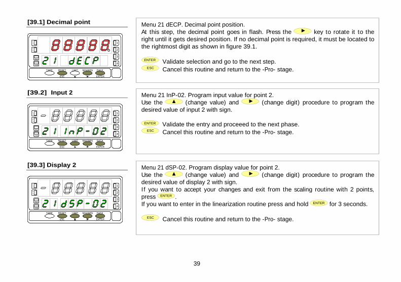
89
39
Menu 21 dECP. Decimal point position. At this step, the decimal point goes in flash. Press the
key to rotate it to the
right until it gets desired position. If no decimal point is required, it must be located to the rightmost digit as shown in figure 39.1.
ENTER Validate selection and go to the next step. ESC Cancel this routine and return to the -Pro- stage.
Menu 21 InP-02. Program input value for point 2. Use the
(change value) and
(change digit) procedure to program the
desired value of input 2 with sign.
ENTER Validate the entry and proceeed to the next phase. ESC Cancel this routine and return to the -Pro- stage.
Menu 21 dSP-02. Program display value for point 2. Use the
(change value) and
(change digit) procedure to program the desired value of display 2 with sign. I f you want to accept your changes and exit from the scaling routine with 2 points, press ENTER . If you want to enter in the linearization routine press and hold ENTER for 3 seconds.
ESC Cancel this routine and return to the -Pro- stage.
282
sign
283 141
digit 4 284 digit 3 285
142 digit 2
286 digit 1 287
143
DISPLAY POINT 18
digit 0 288 sign 289
144 digit 4
290 digit 3 291
145 digit 2
292 digit 1 293
146
DISPLAY POINT 19
digit 0 294 sign 295
147 digit 4
296 digit 3 297
148 digit 2
298 digit 1 299
149
DISPLAY POINT 20
digit 0 300 sign 301
150 digit 4
302 digit 3 303
151 digit 2
304 digit 1 305
152
DISPLAY POINT 21
digit 0 306 sign 307
153 digit 4
308 digit 3 309
154 digit 2
310 digit 1 311
155
DISPLAY POINT 22
digit 0 312 sign 313
156 digit 4
314 digit 3 315
157 digit 2
316 digit 1 317
158
DISPLAY POINT 23
digit 0
[39.1] Decimal point
[39.2] Input 2
[39.3] Display 2
TARE
RESET
LIMIT
MAX/MIN
DATA
ESC
ENTER
M
A X
M I N
HOLD
TARE
1
2
3
4
TARE
RESET
LIMIT
MAX/MIN
DATA
ESC
ENTER
M
A X
M I N
HOLD
TARE
1
2
3
4
TARE
RESET
LIMIT
MAX/MIN
DATA
ESC
ENTER
M
A X
M I N
HOLD
TARE
1
2
3
4

90
40
From the programming phase of the display 2, press and hold ENTER
for 3 seconds to get access to the linearization routine.
From the point nº3, the progress through the routine is made by pressing the ENTER key after programming each value. At any program step, a press of ESC
reverts to the previous point except for the programming phase of point 3, where the
ESC key returns the meter to the -Pro- stage. To terminate the routine for a number of points less than 30, press and hold ENTER for 3 seconds from the last desired point display.
Menu 21 InP-03. Program input value for point 3. Use the
(change value) and
(change digit) procedure to program the
desired value of input 2 with sign.
ENTER Validate the entry and proceeed to the next phase. ESC Cancel this routine and return to the "-Pro-" stage.
Menu 21 dSP-03. Program display value for point 3. Press repeatedly the
key to increment the active digit value and press the
key to move to the next digit until the display reads the desired value with sign. The sign is programmed in the most significant digit [ "0" = positive, "-" = negative]. 1. I f you want to validate the data and advance to the next program point, press
ENTER . 2. I f you want to validate the data and terminate the programming routine with three scaling points, press and hold ENTER for 3 seconds. The meter goes to the "-Pro-" stage. Press
ESC
if you want to cancel the programming and return to the "-Pro-" stage.
The same procedure is used to program the rest of the input-display points except that the ESC
key does not return to the "-Pro-" stage, but to the previous point.
[40.1] Input 3
[40.2] Display 3
TARE
RESET
LIMIT
MAX/MIN
DATA
ESC
ENTER
M
A X
M I N
HOLD
TARE
1
2
3
4
TARE
RESET
LIMIT
MAX/MIN
DATA
ESC
ENTER
M
A X
M I N
HOLD
TARE
1
2
3
4
318
sign
319 159
digit 4 320 digit 3 321
160 digit 2
322 digit 1 323
161
DISPLAY POINT 24
digit 0 324 sign 325
162 digit 4
326 digit 3 327
163 digit 2
328 digit 1 329
164
DISPLAY POINT 25
digit 0 330 sign 331
165 digit 4
332 digit 3 333
166 digit 2
334 digit 1 335
167
DISPLAY POINT 26
digit 0 336 sign 337
168 digit 4
338 digit 3 339
169 digit 2
340 digit 1 341
170
DISPLAY POINT 27
digit 0 342 sign 343
171 digit 4
344 digit 3 345
172 digit 2
346 digit 1 347
173
DISPLAY POINT 28
digit 0 348 sign 349
174 digit 4
350 digit 3 351
175 digit 2
352 digit 1 353
176
DISPLAY POINT 29
digit 0

91
41
A push of ENTER from the programming of the display nº29 gives access to the programming of the scaling point nº30 and last of the routine. The ESC key reverts to the previous point. The programming routine is terminated by a press of ENTER after programming the display 30.
"InP-30". Programming the input of point 30. Press repeatedly the
key to increment the active digit value and press the
key to move to the next digit until the display reads the desired value with
sign. The sign is programmed in the most significant digit [ "0" = positive, "-" = negative].
ENTER Validate the entry and advance to the next program step. ESC Return to the programming of the previous point.
"dSP-30". Programming the display of point 30. Use the
(increment digit) and
(move to next digit) procedure to set the value of the display 30 with sign. The most significant digit is used to set the sign ["0"
= positive, "-" = negative].
ENTER Validate the entry, exit from this routine and go to the "-Pro-" stage. ESC Return to the previous point.
354
sign
355 177
digit 4 356 digit 3 357
178 digit 2
358 digit 1 359
179
DISPLAY POINT 30
digit 0 360 digit 7 / sign 361
180 digit 6
362 digit 5 363
181 digit 4
364 digit 3 365
182 digit 2
366 digit 1 367
183
SETPOINT 1
digit 0 368 digit 7 / sign 369
184 digit 6
370 digit 5 371
185 digit 4
372 digit 3 373
186 digit 2
374 digit 1 375
187
SETPOINT 2
digit 0 376 digit 7 / sign 377
188 digit 6
378 digit 5 379
189 digit 4
380 digit 3 381
190 digit 2
382 digit 1 383
191
SETPOINT 3
digit 0 384 digit 7 / sign 385
192 digit 6
386 digit 5 387
193 digit 4
388 digit 3 389
194
SETPOINT 4
digit 2
[41.1] Value of Input 30
[41.2] Value of Display 30
TARE
RESET
LIMIT
MAX/MIN
DATA
ESC
ENTER
M
A X
M I N
HOLD
TARE
1
2
3
4
TARE
RESET
LIMIT
MAX/MIN
DATA
ESC
ENTER
M
A X
M I N
HOLD
TARE
1
2
3
4

92
42
Figure 42.1 shows the indication corresponding to the access level to the tEACH menu. Press one of the following keys:
ENTER Access to the programming of the first menu parameter. Skip this menu and pass to menu 23 - Display options (page 49).
ESC Exit this menu and return to the -Pro- stage.
This menu allows scaling the display by applying input signal values and keying-in corresponding display values. The decimal point location completes the scaling sequence in the desired units.
Menu 22 tCH-01. Apply input for point 1. The main display reads the actual input signal present at the input connector. Bring the process to the conditions of the first point and press ENTER to take
the displayed input value as the input 1 parameter and go to the programming of the corresponding display.
ESC Cancel this routine and return to the -Pro- stage.
Menu 22 dSP-01. Program display value for point 1. Use the key-in procedure to set the display corresponding to point 1 (
changes
the active digit value,
moves to the next digit to be modified). The sign is programmed in the leftmost digit ["0" = positive, "-" = negative].
ENTER Validate changes and go to the next programming phase. ESC Cancel this routine and return to the -Pro- stage.
[42.1] Access to the Menu
Menu 22 - TEACH (process, load cell and potentiometer)
[42.2] Teach Input Signal 1
[42.3] Value of Display 1
TARE
RESET
LIMIT
MAX/MIN
DATA
ESC
ENTER
M
A X
M I N
HOLD
TARE
1
2
3
4
TARE
RESET
LIMIT
MAX/MIN
DATA
ESC
ENTER
M
A X
M I N
HOLD
TARE
1
2
3
4
TARE
RESET
LIMIT
MAX/MIN
DATA
ESC
ENTER
M
A X
M I N
HOLD
TARE
1
2
3
4
390
digit 1
391 195
digit 0 392 digit 4 393
196 digit 3
394 digit 2 395
197 digit 1
396
DELAY / HYSTERESIS SETPOINT 1
digit 0 397
198 digit 4
398 digit 3 399
199 digit 2
400 digit 1 401
200
DELAY / HYSTERESIS SETPOINT 2
digit 0 402 digit 4 403
201 digit 3
404 digit 2 405
202 digit 1
406
DELAY / HYSTERESIS SETPOINT 3
digit 0 407
203 digit 4
408 digit 3 409
204 digit 2
410 digit 1 411
205
DELAY / HYSTERESIS SETPOINT 4
digit 0 412 ON-OFF SETPOINT 1 0=off, 1=on, 2=track, 3=rscom 413
206 ON-OFF SETPOINT 2 0=off, 1=on, 2=track, 3=rscom
414 ON-OFF SETPOINT 3 0=off, 1=on, 2=track, 3=rscom 415
207 ON-OFF SETPOINT 4 0=off, 1=on, 2=track, 3=rscom
416 COMP SETPOINT 1 0=net, 1=gross, 2=peak, 3=valley, 6=total 417
208 COMP SETPOINT 2 0=net, 1=gross, 2=peak, 3=valley, 4=max, 5=max filter, 6=total
418 COMP SETPOINT 3 0=net, 1=gross, 2=peak, 3=valley, 6=total 419
209 COMP SETPOINT 4 0=net, 1=gross, 2=peak, 3=valley, 6=total
420 HI-LO SETPOINT 1 0=hi, 1=lo 421
210 HI-LO SETPOINT 2 0=hi, 1=lo
422 HI-LO SETPOINT 3 0=hi, 1=lo 423
211 HI-LO SETPOINT 4 0=hi, 1=lo
424 DELAY-HYST SETPONT 1 0=delay, 1=hysteresis-1, 2=hysteresis-2 425
212 DELAY-HYST SETPONT 2 0=delay, 1=hysteresis-1, 2=hysteresis-2

93
43
Menu 22 dECP. Decimal point position. At this step, the decimal point goes in flash. Press the
key to move it to the
right until it gets desired position. If no decimal point is required, it must be located to the rightmost digit as shown in figure 43.1.
ENTER Validate the entry and go to the next step. ESC Cancel this routine and return to the -Pro- stage.
Menu 22 tCH-02. Set input value for point 2. Bring the process to the conditions of the second scaling point. The main display reads the actual input signal present at the input connector. Press ENTER
to take the
displayed input value as the input 2 parameter and go to the programming of the corresponding display.
ESC Cancel this routine and return to the -Pro- stage.
Menu 22 dSP-02. Program display value for point 2. Use the
(change value) and
(change digit) procedure to program the desired value of display 2 with sign. I f you want to accept your changes and exit from the scaling routine with 2 points, press ENTER . If you want to enter the linearization routine press and hold ENTER for 3 seconds.
ESC Cancel this routine and return to the -Pro- stage.
[43.1] Decimal Point
[43.2] Teach Input Signal 2
[43.3] Value of Display 2
TARE
RESET
LIMIT
MAX/MIN
DATA
ESC
ENTER
M
A X
M I N
HOLD
TARE
1
2
3
4
TARE
RESET
LIMIT
MAX/MIN
DATA
ESC
ENTER
M
A X
M I N
HOLD
TARE
1
2
3
4
TARE
RESET
LIMIT
MAX/MIN
DATA
ESC
ENTER
M
A X
M I N
HOLD
TARE
1
2
3
4
426 DELAY-HYST SETPONT 3 0=delay, 1=hysteresis-1, 2=hysteresis-2 427
213 DELAY-HYST SETPONT 4 0=delay, 1=hysteresis-1, 2=hysteresis-2
428 LATCH SETPOINT 1 0=no, 1=yes 429
214 LATCH SETPOINT 2 0=no, 1=yes
430 LATCH SETPOINT 3 0=no, 1=yes 431
215 LATCH SETPOINT 4 0=no, 1=yes
432 BLINK SETPOINT 1 0=LED, 1=LED+blink 433
216 BLINK SETPOINT 2 0=LED, 1=LED+blink
434 BLINK SETPOINT 3 0=LED, 1=LED+blink 435
217 BLINK SETPOINT 4 0=LED, 1=LED+blink
436 TRACK AUTO 0=no, 1=yes 437
218 Nº LINEARIZATION POINTS 2 to 30
438 digit 1 439
219 Nº READINGS SETPOINT MAX
digit 0 440 ANALOG OUTPUT TYPE 0=Vdc, 1=Idc 441
220 ANALOG OUTPUT FILTER 0=off, 1=on
442 sign 443
221 digit 4
444 digit 3 445
222 digit 2
446 digit 1 447
223
ANALOG OUTPUT HI DISPLAY
digit 0 448 sign 449
224 digit 4
450 digit 3 451
225 digit 2
452 digit 1 453
226
ANALOG OUTPUT LO DISPLAY
digit 0 454 digit 4 455
227 digit 3
456 digit 2 457
228 digit 1
458
DIAMETER 1 (VOLUME)
digit 0 459
229 digit 4
460 digit 3 461
230 LENGTH 1 (VOLUME)
digit 2

94
44
From the programming phase of the display 2, press and hold ENTER
for 3 seconds to get access to the linearization routine.
From the point nº3, the progress through the routine is made by pressing the ENTER key after programming each value. At any program step, a press of ESC reverts to the
previous point except for the programming phase of point 3, where the
ESC key returns the meter to the -Pro- stage. To terminate the routine for a number of points less than 30, press and hold ENTER for 3 seconds from the last desired point display.
Bring the process to the conditions of the second scaling point. The main display reads the actual input signal present at the input connector. Press ENTER
to take the
displayed input value as the input 3 parameter and go to the programming of the corresponding display.
ESC Cancel this routine and return to the -Pro- stage.
Menu 21 dSP-03. Program display value for point 3. Press repeatedly the
key to increment the active digit value and press the
key to move to the next digit until the display reads the desired value with sign. The sign is programmed in the most significant digit [ "0" = positive, "-" = negative]. 1. I f you want to validate the data and advance to the next program point, press
ENTER . 2. I f you want to validate the data and terminate the programming routine with three scaling points, press and hold ENTER for 3 seconds. The meter goes to the "-Pro-" stage. Press
ESC
if you want to cancel the programming and return to the "-Pro-" stage.
The same procedure is used to program the rest of the input-display points except that the ESC
key does not return to the "-Pro-" stage, but to the previous point.
[44.1] Teach Input Signal 3
[44.2] Value of Display 3
TARE
RESET
LIMIT
MAX/MIN
DATA
ESC
ENTER
M
A X
M I N
HOLD
TARE
1
2
3
4
TARE
RESET
LIMIT
MAX/MIN
DATA
ESC
ENTER
M
A X
M I N
HOLD
TARE
1
2
3
4
462 digit 1 463
231 digit 0
464 digit 4 465
232 digit 3
466 digit 2 467
233 digit 1
468
DIAMETER 2 (VOLUME)
digit 0 469
234 digit 4
470 digit 3 471
235 digit 2
472 digit 1 473
236
LENGTH 2 (VOLUME)
digit 0 474 digit 4 475
237 digit 3
476 digit 2 477
238 digit 1
478
DIAMETER 3 (VOLUME)
digit 0 479
239 digit 4
480 digit 3 481
240 digit 2
482 digit 1 483
241
LENGTH 3 (VOLUME)
digit 0 484 TANK'S SHAPE 0=no, 1=sphere, 2=cyinder, 3=cylinder+sphere, 4=silo 485
242 DECIMAL POINT (VOLUME) 0=88888, 1=8888.8, 2=888.88, 3=88.888, 4=8.8888
486 EXCITATION 0=24V, 1=10V 487
243 INPUT TYPE 0=process, 1=load cell, 2=Pt100, 3=thermocouple, 4=potentiometer
488 PROCESS TYPE 0=volts, 1=amperes 489
244 THERMOCOUPLE TYPE 0=TCJ, 1=TCK, 2=TCT, 3=TCR, 4=TCS, 5=TCE
490 PROCESS RANGE 0=1V/1mA, 1=10V/20mA 491
245 LOAD CELL RANGE 3=15mV, 2=30mV, 1=60mV, 0=300mV
492 TEMPERATURE SCALE 0=ºC, 1=ºF 493
246 TEMPERATURE RESOLUTION
0=0.1º, 1=1º 494 sign 495
247 digit 1
496
TEMPERATURE OFFSET
digit 0 497
248 DISPLAY DECIMAL POINT 0=88888, 1=8888.8, 2=888.88, 3=88.888, 4=8.8888

A push of ENTER from the programming of the display nº29 gives access to the programming of the scaling point nº30 and last of the routine. The ESC key reverts to the previous point. The programming routine is terminated by a push of ENTER after programming the display 30.
95
45
Menu 22 tCH-30. Set input value for point 30. Bring the process to the conditions of the second scaling point. The main display reads the actual input signal present at the input connector. Press ENTER to take the displayed input value as the input 3 parameter and go to the programming of the corresponding display.
ESC Cancel this routine and return to the -Pro- stage.
"dSP-30". Programming the display of point 30. Use the
(increment digit) and
(move to next digit) procedure to set the value of the display 30 with sign. The most significant digit is used to set the sign ["0" = positive, "-" = negative].
ENTER Validate the entry, exit from this routine and go to the "-Pro-" stage. ESC Return to the previous point.
[41.1] Teach Signal Input 30
[41.2] Value of Display 30
TARE
RESET
LIMIT
MAX/MIN
DATA
ESC
ENTER
M
A X
M I N
HOLD
TARE
1
2
3
4
TARE
RESET
LIMIT
MAX/MIN
DATA
ESC
ENTER
M
A X
M I N
HOLD
TARE
1
2
3
4
498 FILTER P 0 to 9 499
249 FILTER E 0 to 9
500 digit 2 501
250 digit 1
502
READINGS AVERAGE
digit 0 503
251 BRIGHT 0=HI, 1=LO
504 LEFT ZEROS 0=no, 1=yes 505
252 RATE 0=16/s, 1=4/s, 2=1/s
506 ROUND 0=001, 1=002, 2=005, 3=010, 4=020, 5=050, 6=100 507
253 PRINT DATE AND TIME 0=off, 1=on
508 INTEGRATOR 0=no, 1=yes 509
254 TIME BASE 0=second, 1=minute, 2=hour, 3=day
510 digit 3 511
255 digit 2
512 digit 1 513
256
INTEGRAtOR FACTOR
digit 0 514 FACTOR DECIMAL POINT 0=88888, 1=8888.8, 2=888.88, 3=88.888 515
257 TOTALIZER DECIMAL POINT 0=88888888, 1=8888888.8, 2=888888.88, 3=88888.888, 4=8888.8888,
5=888.88888, 6=88.888888, 7=8.8888888 516 sign 517
258 digit 4
518 digit 3 519
259 digit 2
520 digit 1 521
260
LO-CUT
digit 0 522 digit 3 523
261 digit 2
524 digit 1 525
262
SECURITY CODE
digit 0 526 263 SOFT LOCK 1 bit 0 =setpoint 1
bit 1 =setpoint 2 bit 2 =setpoint 3 bit 3 =setpoint 4

96
46
4.2. Integrator
The instrument provides a 8 digit counter (or 7 digits with negative sign) that can be used to accumulate readings in totalizing+batch applications (logic function nº 30 at the rear connector) or to integrate the instantaneous reading using a timebase. The counter is shown on the second display.
-IntEG
23
-oFF-
-IntEG
23
-on-
-IntEG
23
S
tbASE
23
M
tbASE
23
H
tbASE
23
d
tbASE
23
dP
00000.00
00001
FACt
23
00001.
FACt
23
±00.00Lo-Cut
23
The integrator is enabled by setting the option -on- in the menu 23 IntEG. When activated, the logic function nº 30 is inhibited. (NOTE: It is not possible to activate the integrator when the automatic volume calculation option is programmed, see page 57, menu 27 -Vol-).
The value of the integrator appears on the auxiliary display permanently. This allows the instantaneous measurement and the accumulated total be read at the
same time. The second display may show any other variable or be blanked if desired.
The integrator accumulates the reading of the display using a timebase in the following format:
Display Reading x Scale Factor Total(n) = Total(n-1) +
Time Base
As an application example, it is required to show the total fluid quantity that pours out from a drain at a rate of 10 liters per minute. If the instantaneous value is 10.00 and is expressed in lit/min, we must select the timebase in minutes, so the totalizer may show 10.00 lit after one minute, 20.00 lit in two minutes, 600.00 lit in one hour, etc. To read the daily consumption in m3, for instance, we should program a scale factor of 0.001
527 SOFT LOCK 2 bit 0 = input bit 1 = scaling+integrator+volume bit 2 = filters+display+round bit 3 = -
528 SOFT LOCK 3 bit 0 = analog output bit 1 = serial communication output bit 2 = logic inputs bit 3 = direct programming of setpoint values
529
264
SOFT LOCK 4 bit 0 = tare key function bit 1 = - bit 2 = - bit 3 = total lock
530 LOGIC FUNCTION CN2.1 0 to 36 531
265 LOGIC FUNCTION CN2.2 0 to 36
532 LOGIC FUNCTION CN2.3 0 to 36 533
266 LOGIC FUNCTION CN2.4 0 to 36
534 - - 535
267 - -
536 PROTOCOL 1=burster, 2=iso1745, 3=modbus 537
268 BAUD RATE 1=1200, 2=2400, 3=4800, 4=9600, 5=19200
538 ADDRESS UNITS 0 to 9 538
269 ADDRESS TENS 0 to 9
540 TRANSMISSION TO typ9180 0=no, 1=yes 541
270 DELAY RS485 1=30ms, 2=60ms, 3=100ms, 4=300ms, 5=no delay

97
47
The figure 47.1 shows the indication "-IntEG" corresponding to the input stage of the integrator configuration menu.
ENTER To access the integrator configuration. To skip this menu and pass to the next menu.
ESC To cancel this routine and return to the "-Pro-" stage.
This menu allows enabling the integrator option and configuring the function parameters; time base, decimal point, scaling factor and low-cut display. This menu appears only in process and potentiometer configurations.
The first level of this menu offers two choices -on- and -oFF- to enable or disable the integrator respectively. Press the
key to switch the display between the two options to set the desired one. I f the "automatic volume calculation" option is enabled (menu 27 -VoL-) it is not possible to activate the integrator.
ENTER Validate the choice and go to the next program phase. ESC Cancel this routine and return to the "-Pro-" stage.
23 tbASE. Programming the time base. There are four time bases : -S- seconds, -M- minutes, -H- hours and -d- days. Use
to shift around the available options until the display shows the indication corresponding to the desired time base.
ENTER Validate the choice and go to the next program phase. ESC Cancel this routine and return to the "-Pro-" stage.
[47.1] Access to the menu
Menu 23 - INTEGRATOR (for process and potentiometer)
[47.2] ON-OFF Selection
[47.3] Time Base
TARE
RESET
LIMIT
MAX/MIN
DATA
ESC
ENTER
M
A X
M I N
HOLD
TARE
1
2
3
4
TARE
RESET
LIMIT
MAX/MIN
DATA
ESC
ENTER
M
A X
M I N
HOLD
TARE
1
2
3
4
TARE
RESET
LIMIT
MAX/MIN
DATA
ESC
ENTER
M
A X
M I N
HOLD
TARE
1
2
3
4
DINAMIC VARIABLES (READ ONLY) MODBUS Variable Description Format
276 Peak Value Internal peak value Long (2 word) 278 Valley value Internal valley value Long (2 word) 280 Tare value Internal Tare Long (2 word) 282 Batch counter Internal batch counter Integer (1 word) 285 Totalizer Internal totalizer counter Float (2 word) 287 Net value Net value on display (with filters, round and hold) Long (2 word) 289 Gross value Gross value on display (with filters, round and hold) Long (2 word) 291 Input signal value Input signal value on display (with filters and hold) Float (2 word) 293 Setpoint1 Setpoint 1 value Long (2 word) 295 Setpoint2 Setpoint 2 value Long (2 word) 297 Setpoint3 Setpoint 3 value Long (2 word) 299 Setpoint4 Setpoint 4 value Long (2 word) 301 Batch Batch Value on display (with filters and hold) Integer (1 word) 302 Total Total Value on display (with filters and hold) Long (2 word) 304 Peak Peak Value on display (with filters and hold) Long (2 word) 306 Valley Valley Value on display (with filters and hold) Long (2 word) 308 Net Internal net value, without filter nor round Long (2 word) 310 Gross Internal gross value, without filter nor round Long (2 word) 312 Input Input signal value, no filter Long (2 word) 314 Net round Net value with filters and round Long (2 word) 316 Gross round Gross value with filters and round Long (2 word) 318 State of the setpoints and the
logic inputs (0=deactivated, 1=activated)
bit 0 = setpoint 1 status bit 1 = setpoint 2 status bit 2 = setpoint 3 status bit 3 = setpoint 4 status bit 4 = logic input 1 status bit 5 = logic input 2 status bit 6 = logic input 4 status bit 7 = logic input 5 status
Byte

98
48
The totalizer decimal point is programmed in the second display and can be located in any of its 8 digits. In this step, the main display shows the indication "dP" and the second display shows the decimal point in flash. Press repeatedly the
key to
move it to the desired location. I f no decimal point is required, it must be placed to the right of the least significant digit, see figure 48.1.
ENTER Validate the choice and go to the next program phase. ESC Cancel this routine and return to the "-Pro-" stage.
"23 FACt". Programming the scale factor. Press repeatedly the key to increment the active digit and press the key to move to the next digit to the right until the desired scale factor value is completed on the display. A press of ENTER
to validate the entry makes the decimal point go in flash. The factor decimal point position is independent from the one of the display, so it is possible to program any value within the range 0.0001 to 09999. It is not possible to set the scale factor to 0.
ENTER Validate the entry and go to the next program phase. ESC Cancel this routine and return to the "-Pro-" stage.
"Low-Cut" is the value below which the display is not added to the totalizer. Press repeatedly the key to increment the active digit and press the key to move to the next digit to be modified until desired value is completed on the display. The leftmost digit is used to set the sign ["0" = positive, "-" = negative].
ENTER Validate the entry, exit from this routine and go to the "-Pro-" stage. ESC Cancel this routine and return to the "-Pro-" stage.
[48.1] Decimal Point
[48.2] Scale Factor
[48.3] Low-Cut Display
TARE
RESET
LIMIT
MAX/MIN
DATA
ESC
ENTER
M
A X
M I N
HOLD
TARE
1
2
3
4
TARE
RESET
LIMIT
MAX/MIN
DATA
ESC
ENTER
M
A X
M I N
HOLD
TARE
1
2
3
4
TARE
RESET
LIMIT
MAX/MIN
DATA
ESC
ENTER
M
A X
M I N
HOLD
TARE
1
2
3
4
MODBUS Variable Description Format
318 Options installed (0=not installed, 1=installed)
bit 0 = 2RE bit 1 = 4RE bit 2 = RS2 bit 3 = RS4 bit 4 = - bit 5 = BCD bit 6 = ANA bit 7 = -
Byte
digit 0 (LSB) Byte 319 digit 1 Byte digit 2 Byte 320 digit 3 Byte digit 4 Byte 321 digit 5 (MSB) Byte LED's Byte 322
Digits of the main display
- Byte digit 0 (LSB) Byte 323 digit 1 Byte digit 2 Byte 324 digit 3 Byte digit 4 Byte 325 digit 5 Byte digit 6 Byte 326
Digits of the auxiliary display
digit 7 (MSB) Byte Units Byte 327 Tenth Byte Hundreds Byte 328 M
Byte
Version
b
Byte 329 Run/Prog mode 0=run, 1=prog Byte Display overflow (internal) 0=no, 1=yes Byte 330 Input overflow 0=no, 1=yes Byte Display overflow 0=no, 1=yes Byte 331 Totalizer overflow 0=no, 1=yes Byte

49
4.3. Display Options, Filters and Round
The instrument has several types of digital filtering to provide stable readings according to the nature of the input.
The P filter is a programmable low pass filter that smooths the response of the display to input variations. The E filter cuts off the signal variations exceeding from the limits of a band. When the input stabilizes, the band moves to the new value. The Average filter averages the reading over a programmable number of conversions to be displayed at the selected rate.
The round option allows eliminating display jitter by rounding off the meter display by increments of 1, 2, 5, 10, 20, 50 or 100 counts.
In addition, the instrument offers various options so that the user can adjust the reading of the display to meet the system environment conditions, such as selection of two display intensity levels, non-significant zeros (left zeros) and three display update rates.
CnFdSP
20
-SCAL-
21
-tEACH
22
-IntEG
23
0
FILt-P
25
0
FILt-E
25
000
AVErAG
25
-dSP-
24
-FILt-
25
-round
26
-VoL-
27
-HI-
brIGHt
24
-no-
LFt-0
24
16
-rAtE-
24
001
-round
26
-Lo-
brIGHt
24
-YES-
LFt-0
24
4
-rAtE-
24
1
-rAtE-
24

50
Figure 50.1 shows the indication corresponding to the entry level to display options menu. The following actions are available at this stage :
ENTER Access to the display options parameters. Skip this menu and pass to the filtering setup menu
ESC Exit from this routine and return to the -Pro- stage.
This menu allows configuring various options related to the display visualization; the digit brightness, left zeros and display update rate.
Menu 24 brIGHt. Select digit brightness. Use the
key to change the display brightness (current choice is noticed each time it is changed). Select "-HI-" or "-LO-" as desired and:
ENTER Validate the choice and go to the next step. ESC Cancel this routine and return to the -Pro- stage.
Menu 24 LFt-0. Select non-significant zeros. There are two options. Select "-YES-" to read the measured value with all the digits of the display by adding left zeros or select "-NO-" to blank non-significant digits. Use the key to set desired option and:
ENTER Validate the choice and go to the next step. ESC Cancel this routine and return to the -Pro- stage.
[50.1] Access to the Menu
Menu 24
- DISPLAY OPTIONS
[50.2] Digit Brightness
[50.3] Left Zeros
TARE
RESET
LIMIT
MAX/MIN
DATA
ESC
ENTER
M
A X
M I N
HOLD
TARE
1
2
3
4
TARE
RESET
LIMIT
MAX/MIN
DATA
ESC
ENTER
M
A X
M I N
HOLD
TARE
1
2
3
4
TARE
RESET
LIMIT
MAX/MIN
DATA
ESC
ENTER
M
A X
M I N
HOLD
TARE
1
2
3
4

51
Menu 23 -rAtE-. Select reading rate. The reading rate determines the rate at which the display is updated. This parameter affects the display, the setpoints, the analog output and the BCD output. Available values are 16, 4 and 1 per second. Press
to select desired rate. Lower levels produce slower display responses to signal changes. The 16 readings/s option will update the display at the rythm of the signal conversion. For temperature configurations the effective rate is half the selected number of readings/s.
ENTER Validate the choice and return to the "-Pro-" stage. ESC Cancel the programming and go to the "-Pro-" stage.
MULTIFUNCTION
DIGITAL PANEL INSTRUMENT
TYP 9180 MODBUS PROTOCOL COMPATIBLE
INSTRUCTIONS MANUAL
Valid for instruments from s/n 133507
[51.1] Reading Rate
TARE
RESET
LIMIT
MAX/MIN
DATA
ESC
ENTER
M
A X
M I N
HOLD
TARE
1
2
3
4
CO
DE:
307
2711
9
EDIT
ION
: 30
-10-
2006

52
If the display reading is unstable due to small signal variations or noise, the use of digital filters may help to reduce these effects and eliminate display jittering. The filter-E parameter only appears for process, load cell or potentiometer inputs.
The figure 52.1 represents the access level to menu 25 -FILt-. At this stage, you can use one of the following keys:
ENTER To enter the first step of the menu. To skip this menu and pass to the menu 26 -round.
ESC To cancel this routine and return to the "-Pro-" stage.
Menu 25 FILt-P. Set filter P level. The P filter acts as a delay on the display response to signal variations produced at the input. The effect of incrementing this filter level results in a softer response of the display to the input variations. Select filter level from 0 (filter disabled) to 9 using the
key.
ENTER Validate changes and advance to the next step. ESC Cancel this routine and return to the "-Pro-" stage.
Menu 25 FILt-E. Set filter E level. The E filter cuts off input variations exceeding from the limits of a moving band. This band becomes more selective as the filter level is increased. Select filter level from 0 (filter disabled) to 9 using the key.
ENTER Validate changes and advance to the next step. ESC Cancel this routine and return to the "-Pro-" stage.
10. DECLARATION OF CONFORMITY
Manufacturer : burster präzisionmeßtechnik gmbh &
co kg
Address : burster präzisionmeßtechnik gmbh & co kg talstr. 1-5
D-76593
Declares, that the product :
Description : Digital panel multifunction meter
Model : TYP 9180
Conforms with the directives : EMC 89/336/CEE LVD 73/23/CEE
Applicable Standars : EN50081-1 Generic emission EN55022/CISPR22 Class B
Applicable Standars : EN50082-1 Generic immunity IEC1000-4-2 Level 3 Criteria B
Air Discharge 8kV Contact Discharge 6kV
IEC1000-4-3 Level 2 Criteria A 3V/m 80..1000MHz
IEC1000-4-4 Level 2 Criteria B 1kV Power Lines 0.5kV Signal Lines
Applicable Standars : EN61010-1 Generic Safety IEC1010-1 Installation Category II
Transient Voltages <2.5kV Pollution Degree 2 Conductive pollution excluded Insulation Type Enclosure : Double Inputs/Outputs : Basic
Date: 20 January 2004 Signed: José M. Edo Position: Technical Manager
Menu 25 - DIGITAL FILTERS
[52.1] Access to the Menu
TARE
RESET
LIMIT
MAX/MIN
DATA
ESC
ENTER
M
A X
M I N
HOLD
TARE
1
2
3
4
[52.2] Filter-P Level
TARE
RESET
LIMIT
MAX/MIN
DATA
ESC
ENTER
M
A X
M I N
HOLD
TARE
1
2
3
4
[52.3] Filter-E Level
TARE
RESET
LIMIT
MAX/MIN
DATA
ESC
ENTER
M
A X
M I N
HOLD
TARE
1
2
3
4

53
3
Menu 25 AVErAG. Program nº of readings to average. This value represents the number of readings that are summed up together and averaged before the display is updated. Use the
(change value) and
(change digit) keys to program the desired value from 1 to 200.
ENTER Validate all changes in this menu and return to the -Pro- stage. ESC Exit this step and return to the -Pro- stage.
INTRODUCTION TO THE SERIES TYP
9180
This catalogue does not constitute a formal agreement. All information given in this manual is subject to
change without notice.
The SERIES TYP9180 brings a new phylosophy in digital panel instrumentation which is expressed by multipurpose, modular-concept devices providing a rich array of basic functions and advanced capabilities.
With a fully MODULAR DESIGN, it is possible to implement a wide variety of applications by only adding the adequate options.
Intelligence within allows the meter to recognize the options installed and ask for the necessary parameters to properly function within desired margins. The basic instrument without output options omits these data in the program routines.
The instrument's CALIBRATION is made at the factory eliminating the need for adjustment potentiometers. Any circuit or option that may need any adjust incorporates a memory where calibration parameters are stored, making it possible the optional cards be totally interchangeable without need of any subsequent adjust.
Custom CONFIGURATION for specific applications can be made quickly and easily through five front panel keys, following structured choice menus aided by display prompts at each programming step.
Other features of the TYP9180 family include :
CONNECTIONS via plug-in terminal blocks without screws and CLEMP-WAGO clips cable retention system.
DIMENSIONS 96x48x120 mm DIN 43700
CASE MATERIAL UL-94 V0-rated polycarbonate.
PANEL INSTALLATION by means of single part fingertip without screws.
To guarantee the meter's technical specifications, it is advised to check its calibration at periodical intervals according to the ISO9001 standards for the particular application operating criteria. Calibration should be perfomed at the factory or in a qualified laboratory.
[53.1] Average Filter
TARE
RESET
LIMIT
MAX/MIN
DATA
ESC
ENTER
M
A X
M I N
HOLD
TARE
1
2
3
4

54
4
This menu allows selection among six levels of display rounding. When resolution is not critical, a rounding increment other than 1 may help stabilize the display.
The figure 54.1 shows the indication corresponding to the access to the round menu. Press one of the following keys:
ENTER To get access to this menu. To skip this menu and pass to the menu 27 -VoL.
ESC To cancel this menu and return to the "-Pro-" stage.
Menu 26 -round. Select rounding increment. Press repeatedly the
key to scroll through available options for the round filter ["001" = no rounding, "005" = round to 5 counts, "010" = round to 10 counts, "020" = round to 20 counts, "050" = round to 50 counts or "100" = round to 100 counts].
ENTER Validate changes and return to the "-Pro-" stage. ESC Exit this step and return to the "-Pro-" stage.
DIGITAL PANEL INSTRUMENT
MODEL TYP 9180
Menu 25
- ROUND (process, load cell and potentiometer)
[54.1] Access to the menu
TARE
RESET
LIMIT
MAX/MIN
DATA
ESC
ENTER
M
A X
M I N
HOLD
TARE
1
2
3
4
[54.2] Round programming
TARE
RESET
LIMIT
MAX/MIN
DATA
ESC
ENTER
M
A X
M I N
HOLD
TARE
1
2
3
4
Index
1 - TYP 9180 model overview ........................................................................................................................................6 - 7 1.1 Mode RUN: front-panel description........................................................................................................................8 1.2 Mode PROG: front-panel description......................................................................................................................9
2 - Getting started............................................................................................................................................................ 10 2.1 Power and connectors ................................................................................................................................. 11 - 12 2.2 Programming instructions ............................................................................................................................ 13 - 14 2.3 Programming guide............................................................................................................................................ 15
3 - Programming module 10. Input configuration diagram ........................................................................................... 16 - 17
3.1 Program process input. Menu 11.................................................................................................................. 18 - 20 3.1.1 Connections (V, mA) ...................................................................................................................... 21 - 22
3.2 Program load cell input. Menu 12................................................................................................................. 23 - 24 3.2.1 Connections (mV/ V)............................................................................................................................. 25
3.3 Program Pt100 input. Menu 13 .................................................................................................................... 26 - 27 3.3.1 Connections ......................................................................................................................................... 28
3.4 Program thermocouple input. Menu 14......................................................................................................... 29 - 31 3.4.1 Connections (J, K, T, R, S, E) ................................................................................................................ 32
3.5 Program potentiometer input. Menu 15 ............................................................................................................... 33 3.5.1 Connections ......................................................................................................................................... 33

55
5
DIGITAL PANEL INSTRUMENT
MODEL TYP 9180 4 - Programming module 20. Display configuration diagram.........................................................................................34 - 35
4.1 Scaling. Menus 21 and 22 ............................................................................................................................36 - 45 4.2 Integrator. Menu 23 ....................................................................................................................................46 - 48 4.3 Display options, Filters and Round.......................................................................................................................49
4.3.1 Display options. Menu 24......................................................................................................................50- 51 4.3.2 Filters. Menu 25 ..................................................................................................................................52 - 53 4.3.3 Round. Menu 26.........................................................................................................................................54
4.4 Automatic volume calculation. Menu 27 ........................................................................................................55 - 58
5 - Front-panel functions and remote inputs 5.1 Front-panel functions...................................................................................................................................59 - 60 5.2 Remote inputs....................................................................................................................................................61
5.2.1 Table of remote input logic functions....................................................................................................62 - 64 5.2.2 Program remote input logic functions ..........................................................................................................65
6 - Programming parameters lockout .................................................................................................................................66 6.1 Lockout routine ..................................................................................................................................................67
7 - Output options .....................................................................................................................................................68 - 69
8 - Technical specifications.........................................................................................................................................70 - 71 8.1 Dimensions and mounting...................................................................................................................................72
9 - Warranty ....................................................................................................................................................................74
10 - Declaration of conformity...............................................................................................................................................2
ANNEXES. Index ................................................................................................................................................................78
4.4. Display Volume based on Pressure
There are several methods to calculate the volume of a fluid in a tank. If a pressure sensor is placed in the bottom of the tank, the display may be scaled to convert the sensor's pressures into liquid height.
The TYP 9180 provides different approaches to calculate liquid volume.
1. For some special regular tank shapes, if you know the mathematical relationship between pressure and volume, it will only be necessary to scale the display by two points. For example, for a cylindric vertical tank, volume is the product of the cylinder base area and the liquid height.
2. If the tank is irregularly shaped, you can use the linearization feature to readout volume utilizando el método teach y linealización por tramos. The method consists of filling the tank with known amounts of liquid, teach the input and enter the volume at each of the selected points over the height of the tank. The more the number of points used, the more accurate the measurement will be.
3. A third method that offers the instrument to extract volume is to set the automatic volume calculation function. This function can be used when the tank's shape correspond to one of the figures represented at right.
Automatic Volume Calculation
The instrument has most common tank geometry functions pre-programmed to calculate volume; spherical, horizontal cylinder, horizontal cylinder with spherical ends and conical bottom vertical cylinder. The user only has to enter the tank dimensions as requested in the program routine.
D1
D1
D1
L1
L1
Typ 1 - Sphere
Typ 2 - Cylinder
Typ 3 - Sphere+Cylinder
Typ 4 - Silo
L2
L3
L1
D1
D2
D3
L2
L1
D1
D2
L1
D1
D2
L3
D3

56
6
ANALOG OUTPUT
OPTION
BCD PARALLEL
OUTPUT OPTION
MULTI-INPUT CARD
A/D CONVERTER
CIRCUIT
RS232C/ RS485 OUTPUT OPTION
RELAY/ OPTO OUTPUT OPTION
POWER FILTER CIRCUIT
CASE WITH FIXING CLIPS
MAIN CIRCUIT
FRONT COVER
Programming Procedure to Readout Volume
When using this method to display volume, a pressure sensor must be placed at the bottom of the tank to drive a signal proportional to fluid level.
The first scaling phase is to convert the input signal to display height in meters. The height measurement is subsequently used to calculate volume.
The relation between pressure and height is linear, so two scaling points are enough to define the scale.
The decimal point position must be chosen so that the display values are expressed in meters, for example, if the fluid level on top scale is 1.5m, suitable programmings would be 0001.5, 001.50, 01.500 or 1.5000 depending on desired resolution.
Once the signal is scaled to measure level in meters, the second phase is to activate the option VOL to display volume. This option is enabled by selecting one of the available tank shapes (see figure). After this, you must enter the diameter and length of the tank in meters, and finally set the decimal point of the display, which is independent from the decimal point programmed in the scaling procedure.
Volume is expressed in whole liters despite of the point position.
-VoL-
27
no
SHAPE
27
tYP 1
SHAPE
27
tYP 2
SHAPE
27
tYP 3
SHAPE
27
tYP 4
SHAPE
27
02.000
dIAM-1
27
00000.
dIAM-1
27
02.000
dIAM-1
27
06.000
LEn-1
27
00000.
LEn-1
27
02.000
dIAM-1
27
06.000
LEn-1
27
00000.
LEn-1
27
02.000
dIAM-1
27
06.000
LEn-1
27
03.000
dIAM-2
27
00.000
LEn-2
27
03.000
dIAM-3
27
01.000
LEn-3
27
00000.
LEn-3
27
Programming Diagram
DISPLAY AND
KEYBOARD MODULE

57
7
This menu appears exclusively for process and potentiometer configurations. I t is not possible to enable this option if the integrator is active (menu 23) . The automatic volume calculation facility can be only used when the tank's shape is one of the pre-programmed shapes shown in page 55.
The figure 57.1, shows the indication "27 -VoL-" corresponding to the input stage of the automatic volume calculation menu. Use one of the following keys:
ENTER To get acces to this menu. To pass to the Pasar al Submenú 21 - SCAL.
ESC To cancel the programming and return to the "-Pro-" stage.
Selection of the tank's shape. There are five options : -no- to disable this facility, -tYP 1- for sphererical shape, -tYP 2- for horizontal cylinder, -tYP 3-
for horizontal cylinder with end caps and -tYP 4- for conical bottom vertical cylinder (silo). See figures in page 55. Press to choose the most appropriate shape from the list (or set the option -no- to disable volume calculation).
ENTER Validate the choice and advance to the next programming phase. ESC Cancel this routine and return to the "-Pro-" stage.
After selecting the tank's shape, it is necessary to enter the dimensions of the tank. Figure 57.3 shows the phase corresponding to the programming of the diameter D1. Press repeatedly the
key to set the active digit to the desired value and
to move one digit to the right until the value for the diameter D1, in meters is completed on the display (the digits to the right of the decimal point are fractions of meter).
ENTER Validate the entry and advance to the next programming phase. ESC Cancel this routine and return to the "-Pro-" stage.
The TYP 9180 model incorporates new technical and functional characteristics including more filtering options, software lockout, a variety of programmable remote inputs and many other performance capabili-ties that provides an extraordinary flexibility to adapt to a wide range of indication and control needs.
The TYP 9180 model is a digital multifunction instrument whose input stage admits, as selected by the user the following configurable input types:
- PROCESS (V, mA) - LOAD CELL (mV/V) - Pt100 SENSOR - THERMOCOUPLE (J, K, T, R, S, E) - POTENTIOMETER
The input card allows direct connection to a wide variety of transducers, transmitters or primary sensors without need for changing any component or circuit. The meter's configuration for a particular input type is made entirely by software.
An optional 8-digit totalizer/ integrator accumulates time dependent quantities using a timebase or either stores batch readings.
Standard features of the basic instrument include the reading of the input variable plus a selectable second variable in the lower display, max and min readings detection, remote hold, tare operation and a full complement of programmable logic functions.
Special software capabilities are program lock-out for individual menus or the entire program parameters, as well as the possibility to restore factory configuration at any time.
In addition, a variety of plug-in output cards can be installed at any time to meet further system requirements: analog or digital control via 0-10V/ 4-20mA or relay/ transistor outputs and communication via serial RS232C/ RS485 or BCD parallel.
Each option has a separate programming module to configure relating parameters, which is activated when the card is installed. All output options are optoisolated from input signal and power supply.
The basic instrument is a soldered assembly composed of the main board, the display and keyboard module, the power filtering circuit, the A/D converter circuit and the multi-input card (see page 6).
1. MODEL TYP 9180
This instrument conforms with the following directives: 89/336/CEE and 73/23/CEE Caution: Read complete instructions to ensure safety protections.
Menu 27 - AUTOMATIC VOLUME CALCULATION
[57.1] Access to the Menu
TARE
RESET
LIMIT
MAX/MIN
DATA
ESC
ENTER
M
A X
M I N
HOLD
TARE
1
2
3
4
[57.2] Tank's Shape
TARE
RESET
LIMIT
MAX/MIN
DATA
ESC
ENTER
M
A X
M I N
HOLD
TARE
1
2
3
4
[57.3] Diameter 1
TARE
RESET
LIMIT
MAX/MIN
DATA
ESC
ENTER
M
A X
M I N
HOLD
TARE
1
2
3
4

58
8
If you selected the spherical shape (tYP 1), this item does not appear. Please, go to the phase represented by figure 58.2. For the other shapes program the length L1 (see figures in page 55) by using
to increment digit value and
to move to next digit until completing the desired value in meters (the decimal point notation marks the position of whole meters).
ENTER Validate the entry and advance to the next programming phase. ESC Cancel the programming and return to the "-Pro-" stage.
After programming the tank dimensions, the display goes to all zeros with the decimal point in flash. This is the decimal point of the volume display, which is independent of that programmed in the scaling routine. Shift the decimal point to the desired position using . I f no decimal point is required, locate it to the rightmost digit.
ENTER Validate the entry and go to the "-Pro-" stage. ESC Cancel the programming and return to the "-Pro-" stage.
1.1 - RUN MODE: FRONT-PANEL FUNCTIONS
LED HOLD
LED TARE
[58.1] Length 1
TARE
RESET
LIMIT
MAX/MIN
DATA
ESC
ENTER
M
A X
M I N
HOLD
TARE
1
2
3
4
[58.2] Decimal Point
TARE
RESET
LIMIT
MAX/MIN
DATA
ESC
ENTER
M
A X
M I N
HOLD
TARE
1
2
3
4
SILO : The silo shape (tYP 4) is a combination of three parts and requires three diameters and three lengths to be programmed. You may have a tank that is composed of only one or two of the parts in which this shape is divided, according to figures on page 55. To overcame this situation, the length of the missing parts should be programmed to zero. The last phase of this routine is to set the decimal point of the display, go to figure 58.2.
TARE KEY
RESET KEY
LIMIT KEY
MAIN DISPLAY
KEYBOARD IN RUN MODE
LABEL
MAX/MIN KEY
DATA KEY
AUXILIARY DISPLAY
LED MIN
LED MAX
TARE
RESET
LIMIT
MAX/MIN
DATA
ESC
ENTER
M
A
X
M
I
N
HOLD
TARE
1
2
3
4

59
9
1.2 - PROG MODE: FRONT-PANEL FUNCTIONS
TARE key A push of the TARE key causes the current display to be stored in the tare memory . The TARE LED denotes that a tare value other than zero is contained in the memory. The tare value (or offset for a temperature meter) can be displayed on the second display by pressing the MAX/MIN key.
To clear the tare memory, press and hold the RESET
key, then press TARE . Release first TARE , then RESET . I f a tare or tare reset operation is impossible from the front-panel, check the tare key lock settings (see page 67).
5.1 - Front-panel functions The meter provides the following function keys: TARE, RESET, LIMIT and MAX/MIN. The functionality of each one in the "RUN" mode is described below.
LIMIT key During the RUN mode, this key is only operative in case that one of the following output options is installed : 2 relays, 4 relays , 4 NPN transistors or 4 PNP transistors .
The setpoint programmed values appear on the second display at each push of the
LIMIT key independently of whether they are enabled or inhibited. The auxiliary display shows L1, L2, L3 or L4 depending of which value is being read.
During the setpoints routine, the functionnality of the rest of the keys remains active.
5. FRONT-PANEL AND LOGIC INPUT FUNCTIONS
TARE
RESET
LIMIT
MAX/MIN
DATA
ESC
ENTER
M
A X
M I N
HOLD
TARE
1
2
3
4
TARE
RESET
LIMIT
MAX/MIN
DATA
ESC
ENTER
M
A X
M I N
HOLD
TARE
1
2
3
4
ESC KEY
KEY
SECOND DISPLAY
MAIN DISPLAY
KEYBOARD IN PROG MODELABEL
KEY
ENTER KEY
AUXILIARY DISPLAY
TARE
RESET
LIMIT
MAX/MIN
DATA
ESC
ENTER
M
A
X
M
I
N
HOLD
TARE
1
2
3
4

60
10
Packing contents
Instructions manual in English, including Declaration of Conformity.
Digital panel meter model TYP 9180.
Accessories for panel mounting (sealing gasket and fixing clips).
Accessories for wiring connections (plug-in
terminal block
connectors with a fingertip key).
Wiring label sticked to the plastic case
Set of labels with engineering units
Check the packing is complete.
Configuration
Power supply (pages 11 & 12)
The instruments with 115/230V AC power supply, are
set by default for a supply voltage of 230V (USA market 115 V AC).
The instruments with 24/48V AC power supply, are set by default for a supply voltage of 24V.
Check wiring label before applying power to the instrument.
2. GETTING STARTED
Programming instructions (pages 13, 14 & 15)
The software is divided into several independently accessible modules for configuration of the input, the display, the setpoint outputs, the analog output, the communication output and the logic inputs.
Read carefully this section.
Input types (pages 16 & 17)
Verify input configuration before connecting the input signal.
Programming parameters lockout (page 54)
The instrument is shipped from the factory with all programming levels accessible to the operator. Software allows selective lockouts of the programming parameters.
Lockout is recommended after programming the instrument.
MAX/MIN key Recalls the following parameters to the second display : first push recalls peak, second push recalls valley, third push recalls tare (or offset). I f the integrator option is enabled, the fourth push recalls total and, if not enabled but the logic function nº30 (totalizer+ batch) is programmed to one of the user inputs a new push shows the number of batch operations. The last push after this sequence blanks the lower displays.
The auxiliary display indicates which variable is being read in the second display : "HI" = peak, "Lo" = valley, "tA" = tare, "oF" = offset, "bA" = nº of batches. The total value needs all 8 digits to be displayed.
Any selected parameter is permanently displayed and continuously updated if no action is taken.
TO RESET PEAK, VALLEY, TOTAL or BATCH : RESET key Press MAX/MIN
until desired parameter appears on the second display. This parameter may be peak ('HI '), valley ('Lo'), total (auxiliary digits blank or hi part of the total reading) or number of batch operations ('bA').
When desired variable is being read on the lower displays, hold the RESET key and press MAX/MIN . Release first MAX/MIN , then RESET .
A tare or tare reset operation updates automatically the peak and valley readings to the current display value.
ENTER key A momentary push of the ENTER key gives access to the programming mode.
ENTER key (3s) Gives access to the program lock-out routine. Hold ENTER for approximately 3s, at the end of which the meter prompts the indication '- - - -' to enter the security code.
RESET + ENTER (3s) A press of 3s of both RESET and ENTER restores the factory settings to the memory of the instrument. Press RESET first, then ENTER and hold both
until the indication "StorE" appears on the second display.
TARE
RESET
LIMIT
MAX/MIN
DATA
ESC
ENTER
M
A X
M I N
HOLD
TARE
1
2
3
4
TARE
RESET
LIMIT
MAX/MIN
DATA
ESC
ENTER
M
A X
M I N
HOLD
TARE
1
2
3
4

61
11
2.1 - Power supply and connector
To access hardware configuration, remove the meter from the case as shown in figure 11.1.
115/230 V AC: The instruments with 115/230 V AC power are shipped from the factory for 230V AC (USA market 115V AC), see figure 11.2. To change supply voltage to 115V AC, set jumpers as indicated in table 11.1. The wiring label should be modified to match new setup.
24/ 48 V AC: The instruments with 24/48V AC power supply are shipped from the factory for 24V AC, see figure 11.2. To change supply voltage to 48V AC, set jumpers as indicated in table 11.1. The wiring label should be modified to match new setup.
Fig. 11.2. Jumper location for 230 V or 48 V AC
Fig. 11.3. Jumper location for 115 V or 24 V AC
Table 1. Jumper settings.
Pin 1 2 3 4 5 230V AC -
115V AC
- 48V AC -
24V AC
-
Fig. 11.1. Disassembling
Factory Configuration As shipped from the factory, the CN2 connector allows the TARE, MAX/MIN and RESET operations be made in the same way as from the front-panel keyboard and incorporates one more function: the display HOLD.
I f the user programs a '0' (no function) to all input pins, they are automatically set to the default configuration.
CN2 : FACTORY DEFAULT CONFIGURATION PIN (INPUT)
Function Number PIN 1 (INP-1) RESET Function nº 7 PIN 2 (INP-2) HOLD Function nº 9 PIN 3 COMMON, PLC ext. GND
PIN 4 (INP-4) TARE Function nº 1 PIN 5 (INP-5) PEAK/VALLEY Function nº 6
The external electronics (fig.61.2) applied to the CN2 connector must be capable of withstanding 40 V and 20 mA present at all terminals with respect to COMMON. In order to guarrantee the electromagnetic compatibility, please refer to the instructions given on page 12.
5.2 - Logic Functions
The rear connector CN2 provides 4 user programmable opto-coupled inputs that can be operated from external contacts or logic levels supplied by an electronic system. Four different functions may be added to the functions available from the front-panel keys. Each function is associated to one of the CN2 connector pins (PIN 1, PIN 2, PIN 4 and PIN 5) and is activated by applying a falling edge or a low level pulse to the corresponding pin with respect to common (PIN 3). Each pin can be assigned one of the 36 functions listed on the following pages.
Fig.61.1
CN2 LOGIC 3 2 1 J1
6 5 4 J2
CN2 type of input PNP J1 (2-3) J2 (4-5) NPN J1 (1-2) J2 (4-5)
Fig.61.2. Examples of PNP, NPN and contact switch wiring.

62
12
5.2.1 - Table of programmable functions
Definition of the column "Action" Edge : The function is active when a negative edge is applied to the corresponding pin referred to common. Level : The function is active as long as the corresponding pin is held at a low level with respect to common. (*) Factory configuration.
Nº Name Function Action 0 NO None - 1 TARE (*) Adds the current display value to the tare memory Edge 2 RESET TARE Clears the tare memory Edge 3 PEAK Recalls the peak value Level 4 VALLEY Recalls the valley value Level 5 RESET PEAK/VALLEY Resets peak and valley readings Edge 6 VISUAL (*) Recalls various parameters to the second display; Peak, Valley, Tare or Offset
and, if they are active, the Totalizer and the Batch counters. The last action blanks the second display.
Edge
7 RESET (*) In combination with function (1) clears the tare memory. In combination with function (6) clears the peak or valley memories, or the totalizer or the batch counter
Edge
8 HOLD1 Holds the display Level 9 HOLD2 (*) Holds the display and the analog and BCD outputs Level
0 to 9 : DISPLAY AND MEMORY FUNCTIONS
10 to 12 : FUNCTIONS ASSOCIATED WITH THE MEASUREMENT DISPLAY
Nº Name Function Action 10 INPUT Displays the signal input value in V or mA or mV Level 11 GROSS Displays the gross value (measurement value + tare substracted) Level 12 TARE Displays the value of the tare memory Level
CONNECTORS
To perform wiring connections, remove the terminal block from the meter's connector, strip the wire leaving from 7 to 10 mm exposed and insert it into the proper terminal while pushing the fingertip down to open the clip inside the connector as indicated in the figure. Proceed in the same manner with all pins and plug the terminal block into the corresponding meter's connector. Each terminal accept cables of section between 0.08 mm² and 2.5 mm² (AWG 26 ÷ 14). The blocks provide removable adaptors into each terminal to allow proper fastening for cable sections of <0.5 mm².
POWER CONNECTION - CN1
PIN 1 - AC PHASE PIN 2 - GND (GROUND) PIN 3 - AC NEUTRAL
INSTALLATION To meet the requirements of the directive EN61010-1, where the unit is permanently connected to the mains supply it is obligatory to install a circuit breaking device easy reachable to the operator and clearly marked as the disconnect device. WARNING
In order to guarantee electromagnetic compatibility, the following guidelines for cable wiring must be followed: - Power supply wires must be routed separated from signal wires.
Never run power and signal wires in the same conduit. - Use shielded cable for signal wiring and connect the shield to
ground of the indicator (pin2 CN1). - The cable section must be 0.25 mm2
I f not installed and used according to these instructions, protection against hazards may be impaired.
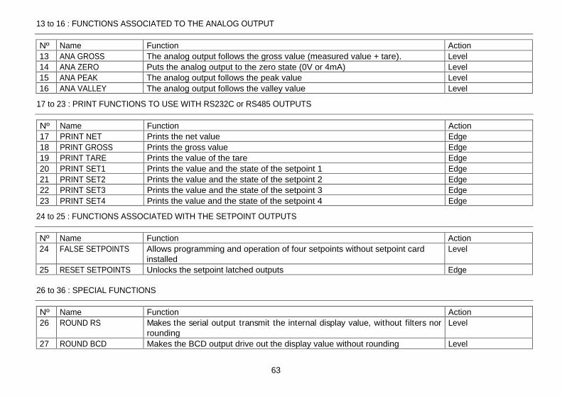
63
13
Nº Name Function Action 13 ANA GROSS The analog output follows the gross value (measured value + tare). Level 14 ANA ZERO Puts the analog output to the zero state (0V or 4mA) Level 15 ANA PEAK The analog output follows the peak value Level 16 ANA VALLEY The analog output follows the valley value Level
13 to 16 : FUNCTIONS ASSOCIATED TO THE ANALOG OUTPUT
17 to 23 : PRINT FUNCTIONS TO USE WITH RS232C or RS485 OUTPUTS
Nº Name Function Action 17 PRINT NET Prints the net value Edge 18 PRINT GROSS Prints the gross value Edge 19 PRINT TARE Prints the value of the tare Edge 20 PRINT SET1 Prints the value and the state of the setpoint 1 Edge 21 PRINT SET2 Prints the value and the state of the setpoint 2 Edge 22 PRINT SET3 Prints the value and the state of the setpoint 3 Edge 23 PRINT SET4 Prints the value and the state of the setpoint 4 Edge
24 to 25 : FUNCTIONS ASSOCIATED WITH THE SETPOINT OUTPUTS
Nº Name Function Action 24 FALSE SETPOINTS Allows programming and operation of four setpoints without setpoint card
installed Level
25 RESET SETPOINTS Unlocks the setpoint latched outputs Edge
26 to 36 : SPECIAL FUNCTIONS
Nº Name Function Action 26 ROUND RS Makes the serial output transmit the internal display value, without filters nor
rounding Level
27 ROUND BCD Makes the BCD output drive out the display value without rounding Level
2.2 - Programming Instructions
Access to the programming mode When power is applied to the instrument, the display briefly illuminates all segments and LED's then shows the software version and finally enters in the normal mode. Press ENTER
to enter in the programming mode. The second display
shows the indication "-Pro-" (fig. 13.1).
Exit from the programming mode without saving data From any step of the program routines, a push of ESC returns the meter to the -Pro- stage. From this point, a new push of
ESC shows momentarily the indication "qUIt" on the second display, the meter exits from the programming mode, restores the previous configuration and returns to the normal operation. Any parameter change made before exiting in this mode is discarded.
Save changes in the configuration In the programming mode, the instrument returns to the -Pro- stage at the end of each program menu. The data changes are not saved at this point, to keep changes in the configuration parameters press ENTER , the second display shows momentarily the indication "StorE" while the new configuration is saved in the memory. After the instrument returns to the run mode.
Guidelines on programming instructions The programming software is divided into 6 modules. Each module is organized in several independently accessible menus and each menu contains a list of parameters necessary to configure a specific function of the meter. From the -Pro- stage, press repeatedly to cycle around the existing modules : module 10 = Input configuration, module 20 = display configuration, module 30 (if option is installed) = setpoints, module 40 (if option is installed) = analog output, module 50 (if option is installed) = serial outputs and module 60 = logic functions. Press ENTER to get access to the selected module.
TARE
RESET
LIMIT
MAX/MIN
DATA
ESC
ENTER
M
A X
M I N
HOLD
TARE
1
2
3
4
Fig. 13.1. PROG mode first step (-Pro- stage)
quit
quit
quit
quit
quit
quit
quit
Store
menu 11 menu 21
menu 31
menu 41
menu 51
menu 61
TARE
RESET
LIMIT
MAX/MIN
DATA
ESC
ENTER
M
A
X
M
I
N
HOLD
TARE
1
2
3
4
TARE
RESET
LIMIT
MAX/MIN
DATA
ESC
ENTER
M
A
X
M
I
N
HOLD
TARE
1
2
3
4
TARE
RESET
LIMIT
MAX/MIN
DATA
ESC
ENTER
M
A
X
M
I
N
HOLD
TARE
1
2
3
4
TARE
RESET
LIMIT
MAX/MIN
DATA
ESC
ENTER
M
A
X
M
I
N
HOLD
TARE
1
2
3
4
TARE
RESET
LIMIT
MAX/MIN
DATA
ESC
ENTER
M
A
X
M
I
N
HOLD
TARE
1
2
3
4
TARE
RESET
LIMIT
MAX/MIN
DATA
ESC
ENTER
M
A
X
M
I
N
HOLD
TARE
1
2
3
4
TARE
RESET
LIMIT
MAX/MIN
DATA
ESC
ENTER
M
A
X
M
I
N
HOLD
TARE
1
2
3
4

64
14
26 to 36 : SPECIAL FUNCTIONS (cont.)
Nº Name Function Action 28 ASCII Envío de los cuatro últimos dígitos de display a un indicador Micra-S Edge 29 SETS INHIBIT Suspends setpoint operations and keeps the outputs to their OFF state Level 30 BATCH Adds the current display value to the totalizer and increments the batch
counter in one unit. If the integrator is enabled (menu 23), this function does not work
Edge
31 VIEW TOTAL Calls the totalizer value to the second display Level 32 VIEW BATCH Calls the batch counter to the second display Level 33 RESET
TOTAL+BATCH Resets the totalizer and the batch counter Edge
34 STOP TOTAL Inhibits the integrator operation Level 35 PRINT
TOTAL+BATCH Prints out the totalizer value and the batch counter value. I f the integrator is enabled, only the totalizer value is printed.
Edge
36 PRINT PEAK Hold and print max reading. When this function is programmed the peak value detection is stopped. In the activation edge, the peak register is cleared from the memory and the unit starts reading new peak values. In the deactivation edge, the peak value registered during the time the function was active is printed out through the serial output
Level
In the step-by-step instructions, you are given the action of the three buttons mainly used to program data. The normal procedure at each step is to push on
a
number of times to make changes and push on ENTER
to validate changes and
advance to the next programming step. At the end of a complete menu sequence the meter returns to the -Pro- stage, where :
ENTER to save changes and exit ESC to discard changes and exit
to select among available options
[page nº/figure nº] Mnemo
The auxiliary display shows the indentification of the current menu.
The second display shows the parameter being programmed.
The programming instructions are composed by a general description and a series of step-by-step instructions to be followed sequentially. Each menu step is represented by an illustration of the display and keyboard module with indications (displays and LED's), reference [page number . figure number] and a text describing the action of each key at current step.
TARE
RESET
LIMIT
MAX/MIN
DATA
ESC
ENTER
M
A X
M I N
HOLD
TARE
1
2
3
4
With respect to the figures in the step-by-step instructions, the display indications may have the following meanings :
1./ The first display shows one of the available options with filled-out segments. That means that the display shows the choice made previously. The use of allows to select from available options.
2./ A series of black "8" also represents the display indication of a previous choice, with the difference that it cannot be changed in the current step. I f it
is already the desired parameter, you may exit from the menu by a push of ESC
without making changes or, if wanted to modify it, a push of ENTER
advances the meter to the next step where changes are allowed.
3./ A series of white "8" represents any numerical value that is programmed by the and buttons.

65
15
Menu 61 Inp-1. Assign logic function to PIN 1. The main display shows the function number assigned to logic input 1. Refer to the table to select function and use the key to change the number if desired.
Pass to the programming of the following logic input. ENTER Validate changes and return to the -Pro- stage.
ESC Exit from this menu and go to the -Pro- stage.
Process indicator: 1. Input programming, pages. 16 - 20 (M). 2. Signal wiring, pages. 21 - 22 (M). 3. Scaling, pages. 34 - 45 (M). 4. Configure the integrator option, pages 46 - 48 (op) 5. Program remote inputs, pages. 61 - 65 (R). 6. Install and configure output options, refer to respective
manual (op). 7. Lockout programming, pages. 66 - 67 (R).
Load cell indicator: 1. Input programming, pages. 16, 23 and 24 (M). 2. Signal wiring, page. 25 (M). 3. Configure the display, pages. 50 - 54 (M). 4. Program remote inputs, pages. 61 - 65 (R). 5. Install and configure output options, refer to respective
manual (op). 6. Lockout programming, pages. 66 - 67 (R).
Pt100 thermometer: 1. Input programming, pages. 17, 26 and 27 (M). 2. Signal wiring, page. 28 (M). 3. Program display options, pp. 34 - 35 and 42 - 45 (R). 4. Program remote inputs, pages. 61 - 65 (R). 5. Install and configure output options, refer to respective
manual (op). 6. Lockout programming, pages. 66 - 67 (R).
Thermocouple meter: 1. Input programming, pages. 17 and 29 - 31 (M). 2. Signal wiring, page. 32 (M). 3. Program display options, pp. 34 - 35 and 42 - 45 (R). 4. Program remote inputs, pages. 61 - 65 (R). 5. Install and configure output options, refer to respective
manual (op). 6. Lockout programming, pages. 66 - 67 (R).
Potentiometer indicator: 1. Input programming, pages. 17 and 33 (M). 2. Set excitation jumper, page. 18 (M). 3. Signal wiring, page. 33 (M). 4. Scaling, pages. 34 - 45 (M). 5. Configure the integrator option, pages 46 - 48 (op) 6. Program remote inputs, pages. 61 - 65 (R). 7. Install and configure output options, refer to respective
manual (op). 8. Lockout programming, pages. 66 - 67 (R).
2.3 - Programming guide
The steps listed here below should be followed to properly configure the indicator according to desired input. Steps are marked depending on whether they are mandatory (M), recommended (R) or optional (op).
Menu 61 - Program Logic Input 1
[65.2] Logic input PIN 1
5.2.2 - Program the logic functions
Press ENTER to enter in the programming mode (-Pro-
level) and press repeatedly
until the indication shown in figure 65.1 appears on the display. From this stage press ENTER to acceed the logic inputs configuration. The key rotates around the four logic inputs to view the function number assigned to each pin. The key changes the number if desired.
To program the logic inputs follow the procedure described below for input 1.
TARE
RESET
LIMIT
MAX/MIN
DATA
ESC
ENTER
M
A X
M I N
HOLD
TARE
1
2
3
4
Fig. 65.1: Logic inputs configuration module
TARE
RESET
LIMIT
MAX/MIN
DATA
ESC
ENTER
M
A X
M I N
HOLD
TARE
1
2
3
4

66
16
Menu 12
Load cell: a) Input range [300mV, 60mV, 30mV, 15mV].
3. INPUT CONFIGURATION
Menu 11
Process: a) Input type [VoLt= volts, AMP= milliamperes]. b) Input range [1V, 10V] or [1mA, 20mA]. Excitation [24V, 10V].
The instrument is supplied with all software programming parameters accessible to operator's modifications. After completing the software configuration, it is recommended to take the following steps:
1. Lockout programming parameters to prevent from accidental or unauthorized modifications.
2. Lockout the tare key operation.
3. The lockout can be applied to everything or to specific menus or parameters. I f some parameters should be reprogrammed frequently, make a partial lock leaving such parameters accessible. I f no subsequent adjust must be made, make a total lock.
4. The access to the lockout routine is allowed by entering a safety code. At fabrication this code is set to 0000. We recommend to change this code and to write it down and keep safe.
6. PARAMETER LOCKOUTS
TOTAL LOCKOUT
The access to the programming routines to read data is allowed even if all parameters are locked out, but it won t be possible to enter or modify data. In this case, when entering in the programming mode, the second display shows the indication -dAtA- instead of -Pro-.
SELECTIVE LOCKOUT
When only some parameters are locked out, all configuration data can be read but only non-protected parameters can be modified. In such case, when entering in the programming mode, the second display shows the indication -Pro-.
Selective lock-outs include the following groups:
Setpoint 1 configuration (menu 31).
Setpoint 2 configuration (menu 32).
Setpoint 3 configuration (menu 33).
Setpoint 4 configuration (menu 34).
Input configuration (module 10).
Scaling (menus 21/22, 23 and 27).
Display options and filtering (menus 24, 25 and 26).
Analog output configuration (module 40).
Serial output configuration (module 50).
Logic inputs configuration (module 60).
Direct access to the programming of the setpoint values
Those that refer to optional outputs only appear if the corresponding option is installed.
- P r o C -
1 1
C n F I n P
1 0
- I n P u t -
1 1
V o L t
- I n P u t -
1 1
A M P
r A n G E
1 1
1 - V
r A n G E
1 1
1 0 - V
- L o A d -
1 2
r A n G E
1 2
3 0 0 - mV
r A n G E
1 2
6 0 - mV
r A n G E
1 2
3 0 - mV
r A n G E
1 2
1 5 - mV
- P r o -
S u P P L Y
1 1
2 4 - V
S u P P L Y
1 1
1 0 - V
r A n G E
1 1
1 - m A
r A n G E
1 1
2 0 - m A
- P r o -

67
17
Menu 15
Potentiometer None.
Menu 13
Pt100 thermometer: a) Display units [ ºC, ºF ]. b) Resolution [ 0.1º, 1º ]. c) Offset [-9.9° to +9.9°, -99° to + 99°].
Menu 14
Thermocouple thermometer: a) Thermocouple type [ J, K, T, R, S, E ]. b) Display units [ ºC, ºF ]. c) Resolution [ 0.1º, 1º ]. d) Offset [-9.9° to +9.9°, -99° to +99°].
MODULE 10 - INPUT CONFIGURATION ("CnFInP")
The figure shows the complete input configuration module which is divided into five menus. Each menu corresponds to a specific configuration of the meter. You may only need to program the parameters of the desired configuration (process, load cell, thermocouple, Pt100 or potentiometer).
6.1 - Lockout programming routine
The lock-out programming routine is entered by depressing the ENTER key for 3 seconds and introducing a security code. This gives access to either the parameter list or to change the code if desired.
If the user opts for changing the code, the unit asks for the new one and returns to the normal operation. The old code is replaced with the user selected one, that will be asked next time this routine is entered.
When the user enters the parameter list, each parameter is indicated in the second display, while in the first one a blinking digit allows setting a 1 to lock this item, or a 0 to free it.
There are two ways to lock-out the program; One is to lock everything, which is accomplished by setting a 1 in the tot-LC parameter (the remaining parameters are skipped except the tare key lock). The second is to individually lock some parts of the program menus leaving free those parts which are more liable to have changes during normal operation.
88888
3s?
-
-
-
-
CodE
-YES-
CHAnG
-no-
CHAnG
0
tot-LC
tot-LC?
0
tArE
0
SEt1
0
SEt2
0
SEt3
0
SEt4
0
InPut
0
SCAL
0
FILt
0
AnAout
0
rs coM
0
LoGInP
0
SP VAL
-
-
-
-
CodE
code OK
1
0
yes
no
yes
- P o t -
1 5
- P t 1 0 0
1 3
-
o
C -
- P t 1 0 0
1 3
-
o
F -
- P t 1 0 0
1 3
0. 1
o
- P t 1 0 0
1 3
1
o
- P t 1 0 0
1 3
o F F S E t
1 3
0 0.0
- P r o -
- t C -
1 4
-
o
C -
- t C -
1 4
-
o
F -
- t C -
1 4
0. 1
o
- t C -
1 4
1
o
- t C -
1 4
o F F S E t
1 4
0 0.0
- P r o -
- t C -
1 4
t Y P E - J
- t C -
1 4
t Y P E - K
- t C -
1 4
t Y P E - t
- t C -
1 4
t Y P E - r
- t C -
1 4
t Y P E - S
- t C -
1 4
t Y P E - E
- P r o -

68
18
Output options with instructions manual edited before December 1999, work properly with new versions of TYP 9180 but some new features may not be described in the options manual. I f you are using an older output card connected to a new TYP 9180 and you want to take benefit of the new functions (see page 60) , please call for an updated edition of the options manual.
Optionally, model TYP 9180 can incorporate one or several output options for communications or control including :
COMMUNICATION 9180-Vxx1x Serial RS232C 9180-Vxx2x Serial RS485 9180-Vxx3x BCD 24V/TTL
CONTROL 9180-Vx1xx Analogue 4-20 mA, 0-10 V 9180-Vxxx1 2 SPDT relays 8 A 9180-Vxxx2 4 SPST relays 5 A 9180-Vxxx3 4 open-collector NPN outputs 9180-Vxxx4 4 open-collector PNP outputs
All options are optoisolated with respect to the input signal.
The options are supplied with a specific instructions manual describing characteristics, installation, connections and pro-gramming. The output cards are easily installed on the meter's main board by means of plug-in connectors and each one activates its own programming module that provides complete software-configuration. Additional capabilities of the unit with output options :
Control and processing of limit values via ON/OFF logic outputs (2 relays, 4 relays, 4 NPN outputs or 4 PNP outputs) or proportional output (4-20 mA or 0-10 V).
Communication, data transmission and remote programm-ing via serial interface.
For more detailed information on characteristics, applications, mounting and programming, please refer to the specific manual supplied with each option.
7. OUTPUT OPTIONS
To have access to the input configuration module, press
ENTER
to pass from the run mode to the programming mode
and press
to make the lower displays show the
indication "10 CnFInP" (fig. 18.1).
3.1 - Program process input
The process indicator accepts inputs in volts or milliamperes and provides three selectable transducer excitation voltages.
Configurable parameters: a) Type of input : volts or milliamperes
b) Input range in volts or milliamperes :
"1V", range -1V to +1V,
"10V", range -10V to +10V,
"1mA", range -1mA to +1mA,
"20mA", range -20mA to +20mA,
c) Sensor excitation. Available excitation voltages are 24V, 10V or 5V. The 5V supply is set by selecting 10V in the software routines then placing a jumper in the position shown in figure 18.2.
TARE
RESET
LIMIT
MAX/MIN
DATA
ESC
ENTER
M
A X
M I N
HOLD
TARE
1
2
3
4
Jumper ON = EXC. 5V Jumper OFF = EXC. 10V
Fig. 18.2: 10V/5V excitation jumper
Fig. 18.1: Input configuration module

19
Menu 11 rAnGE. Select input range. There are two ranges for each input type [1-V / 10-V if input type is 'VoLt' and 1mA
/ 20mA if input type is 'AMP']. Press to change this parameter if desired.
ENTER Validate changes and advance to the next programming step. ESC Exit from this routine and return to the -Pro- stage.
Figure 19.1 shows the indication corresponding to the access stage to process input configuration. The following actions are available at this stage :
ENTER Access to the process input parameters. Skip this menu and pass to the load cell configuration (p. 24).
ESC Exit from this routine and return to the -Pro- stage.
Menu 11 Input. Select input type. The display shows the previous configuration [VoLt = voltage input, AMP
= current input]. Press to change this parameter if desired.
ENTER Validate the choice and advance to the next programming step. ESC Exit from this routine and return to the -Pro- stage.
69
The figure shows the main circuit board locations of the available output options. Each plug-in location can accept only one card from a particular function type.
The options 9180-Vxxx1, 9180-Vxxx2, 9180-Vxxx3 and 9180-Vxxx4 are for setpoint control and only one of them can be installed in the M5 location. The options 9180-Vxx1x and 9180-Vxx2x are for communication and only one of them can be installed in the M1 location. The 9180-Vx1xx option provides selectable 0-10V and 20mA analog output and is installed in the M4 location.
Up to three output options can be present at a time and operate simultaneously:
- ANALOGUE, 0-10V or 4-20mA - RS232C or RS485 (one of them), - 2 RELAYS, 4 RELAYS or 4 NPN or 4 PNP outputs (one of them).
The 9180-Vxx3x output is exclusive and it does not allow any of the others. This option is attached to the main circuit board by means of a 18-pin FLAT cable.
This menu configures the meter as a process indicator. Programmable parameters are the input type (volts or milliamperes), input range and transducer's excitation.
Menu 11 - PROCESS
[19.3] Input range
[19.1] Access to menu 11
[19.2] Input type
TARE
RESET
LIMIT
MAX/MIN
DATA
ESC
ENTER
M
A X
M I N
HOLD
TARE
1
2
3
4
TARE
RESET
LIMIT
MAX/MIN
DATA
ESC
ENTER
M
A X
M I N
HOLD
TARE
1
2
3
4
TARE
RESET
LIMIT
MAX/MIN
DATA
ESC
ENTER
M
A X
M I N
HOLD
TARE
1
2
3
4

20
Menu 11 SuPPLY. Select excitation voltage. The meter provides two software selectable excitation voltages [10-V and 24-V] that alternate on the display by pressing the
key. To set the excitation supply to 5V
DC, select the option '10-V' and place the jumper shown in figure 18.2.
ENTER Validate changes, exit from this menu and return to the -Pro- stage. ESC Exit from this routine and return to the -Pro- stage.
70
[20.1] Excitation Supply
TARE
RESET
LIMIT
MAX/MIN
DATA
ESC
ENTER
M
A X
M I N
HOLD
TARE
1
2
3
4
Temperature input
Cold junction compensation .................. -10 ºC to +60 ºC
Cold junction...............................±(0.05 ºC/ ºC +0.1 ºC)
Pt100 excitation current................................. < 1 mA DC
Max. cable resistance ...................40 / cable (balanced)
Temperature coefficient...............................100 ppm/ ºC
Input Range (0.1 º) Accuracy (0.1º) Range (1º) Accuracy (1º)
-50.0 to +800.0 ºC
0.4% L ±0.6 ºC
-50 to +800 ºC
0.4% L ±1 º C TC J
-58.0 to +1472.0 ºF
0.4% L ±1 ºF -58 to
+1472 ºF 0.4% L ±2 º F
-50.0 to +1200.0 ºC
0.4% L ±0.6 ºC
-50 to +1200 ºC
0.4% L ±1 º C TC K
-58.0 to +2192.0 ºF
0.4% L ±1 ºF -58 to
+2192 ºF 0.4% L ±2 º F
-150.0 to +400.0 ºC
0.4% L ±0.6 ºC
-150 to +400 ºC
0.4% L ±1 º C TC T
-302.0 to +752.0 ºF
0.4% L ±1 ºF -302 to +752 ºF
0.4% L ±2 º F
-50.0 to 1700.0 ºC
0.5% L ±2 ºC -50 to
1700 ºC 0.5% L ±4 º C
TC R -58.0 to
+3092.0 ºF 0.5% L ±4 ºF
-58 to +3092 ºF
0.5% L ±7 º F
-50,0 to 1700,0 ºC
0.5% L ±2 ºC -50 to
1700 ºC 0.5% L ±4 º C
TC S -58.0 to
+3092.0 ºF 0.5% L ±4 ºF
-58 to +3092 ºF
0.5% L ±7 º F
-50.0 to 1000.0 ºC
0.4% L ±1 ºC -50 to
1000 ºC 0.4% L ±2 ºC
TC E -58.0 to
+1832.0 ºF 0.4% L ±2 ºF
-58 to +1832 ºF
0.4% L ±4 ºF
-100.0 to +800.0 ºC
0.2% L ±0.6 ºC
-100 to +800 ºC
0.2% L ±1 ºC Pt100
-148.0 to +1472.0 ºF
0.2% L ±1 ºF -148 to
+1472 ºF 0.2% L ±2 ºF
8. TECHNICAL SPECIFICATIONS
INPUT SIGNAL
Configuration.......................... differential asymmetrical
Process input Voltage Current
Voltage............................... ±10V DC .........±20mA DC
Max. resolution ....................... 0.1mV ................... 1µA
Input impedance........................1M ...................15
Excitation ........................24V (30mA), 10/ 5V (120mA)
Max error ................. ± (0.1% of the reading +3 digits)
Coeficiente de temperatura....................... 100 ppm/ ºC
Load cell input
Voltage.................................................... ±300 mV DC
Max. resolution ................................................0.15 µV
Input impedance............................................. 100 M
Excitation .......................................... 10/ 5V (120 mA)
Max error ................. ± (0.1% of the reading +6 digits)
Temperature coefficient............................ 100 ppm/ ºC
Potentiometer input
Voltage..........................................................±10V DC
Input impedance.................................................. 1M
Display resolution.............................................0.001%
Max error ................. ± (0.1% of the reading +3 digits)
Temperature coefficient............................ 100 ppm/ ºC

71
21
PROCESS input in volts
3.1.1 - Signal wiring ( V, mA )
PIN 6 = EXC [excitation supply ( )] PIN 5 = +EXC [excitation supply (+)] PIN 4 = +IN [input mA (+)] PIN 3 = IN [input V ( ) or mA ( )] PIN 2 = +IN [input V (+)] PIN 1 = N/C [not connected]
Instrument's rear view
Refer to wiring instructions in page 12.
ENVIRONMENTAL (indoor use)
Operating temperature .......................-10 ºC to +60 ºC
Storage temperature ..........................-25 ºC to +85 ºC
Relative humidity ................................ <95 % at 40 ºC
Max. altitude............................................ 2000 meters
MECHANICAL
Dimensions.......................................... 96x48x120 mm
Panel cutout ............................................... 92x45 mm
Weight ...............................................................600 g
Case material.................UL 94 V-0 rated polycarbonate
FUSES (DIN 41661) - Not supplied
TYP 9180 (230/115V AC).......................F 0.2 A / 250 V
TYP 9180 (24/48V AC) ..........................F 0.5 A / 250 V
A/D CONVERSION
Technique ................................................... dual slope
Resolution .....................................................(±17 bit)
Rate.....................................................................16/s
ACCURACY at 23º ± 5º C
Temperature coefficient ........................... 100 ppm/ ºC
Warm-up time .................................................. 10 min
POWER SUPPLY
AC voltages ................230/115 V, 24/48 V 50/60 Hz AC
Consumption .............5W (without options), 10W (max)
DISPLAY
Main.............. -99999/ +99999, 6 digits red LED 14 mm
Secondary ..............................6 digits green LED 8 mm
Auxiliary .................................2 digits green LED 8 mm
Decimal point ........................................programmable
LEDs ............................ 4 functions and 4 output status
Reading rate.................................. 62 ms/ 250 ms/ 1 s (thermometers)........ 125 ms/ 500 ms/ 2 s
Positive overrange ............................................. oVFLo
Negative overrange........................................... -oVFLo
TYP 9180

72
22
PROCESS indicator with mA input
8.1 - Dimensions and mounting
To mount the instrument into the panel, make a cutout of 92x45mm. Slide the sealing gasket over the instrument's case to the bezel and insert the instrument through the panel cutout from the front.
PANEL CUTOUT
92 mm
45 m
m
Place the fixing clips on both sides of the case and push them over the rear until they touch the panel. Apply pressure to engage the tabs on the fixing clips to the slots of the case.
To remove the instrument from the panel, pull outwards the fixing clips from the rear tabs to disengage and slide them back over the case.
CLEANING: The font cover should be cleaned only with a soft cloth soaked in neutral soap products. DO NOT USE SOLVENTS
SEALING GASKET
PANEL
FIXING CLIPS
EXCITATION SUPPLIED BY TYP 9180

73
23
All products are warranted against defective material and workmanship for a period of three years from date of delivery.
If a product appears to have a defect or fails during the normal use within the warranty period, please contact the distributor from whom you purchased the product.
This warranty does not apply to defects resulting from action of the buyer such as mishandling or improper interfacing.
The liability under this warranty shall extend only to the repair of the instrument; no responsibility is assumed by the manufacturer for any damage which may result from its use.
9. WARRANTY
3.2 - Program load cell input
Refer to the cell manufacturer's documentation, particularly with respect to the cell sensitivity and supply voltage specifications.
As load cell indicator the meter's function is to measure forces (weight, pressure, torque...) which are converted to a millivolts signal by a bridge type transducer such as load cell and applied to the input of the meter. The instrument supplies 10V or 5V to feed the transducer as selected by jumper (fig. 25.1). These voltages can feed up to 4 cells connected in parallel with 10V or up to 8 cells connected in parallel with 5V without need for an external source (fig. 25.2).
Example: 4 cells with 2mV/V sensitivity are parallel connected to the meter input. With an excitation voltage of 10V, the max. voltage generated by the cells is 20mV. In the same case but with an excitation of 5V, the max. voltage generated by the cells is 10mV.
Software configuration requires selection of the input range which may be selected high enough for the maximum input signal to avoid overloads. There are four ranges: ±15mV, ±30mV, ±60mV and ±300mV
Example: I f a weighing process gives 20mV to the meter input with maximum load, the best range should be 30mV.
BATCH FUNCTION Operation by logic input
Function nº 30 -BATCH-
is designed to be used in batch weighing applications where it is required to read the accumulated total of a product quantity per cycle, or day and to keep count of the number of weighing operations.
A sensor connected to a logic input with function 30 detects the presence of a weight and pulls low the logic input which makes the instrument add the measured value to the totalizer and increment the batch counter in one unit.
The meter keeps in memory the totalizer and the batch count in a power failure or disconnection from the power source. These parameters can be displayed permanently on the second display as selected by the user.

77
27
ANNEXES
MODEL TYP 9180
Menu 13 -Pt100. Select temperature units. Use to select desired units ["ºC" = Celsius, "ºF" = Fahrenheit].
ENTER Validate changes and pass to the next program step. ESC Exit from this routine and return to the "-Pro-" stage.
Menu 13 -Pt100. Select resolution. Press
to switch between the indications "0.1º" (resolution to tenths of degree)
and "1º" (resolution to degrees).
ENTER Validate changes and pass to the next program step. ESC Exit from this routine and return to the "-Pro-" stage.
Menu 13 oFFSEt. Program the display offset. The previously programmed offset appears on the display with the first digit in flash. To change the value, press
to increment the active digit value (the first digit can only be '0' or a minus sign). Press
to shift to the next digit to be modified and repeat these operations until desired offset is completed on the display (max values are ±99° with 1° resolution and ±9.9° with 0.1° resolution. The TARE LED lights whenever the offset has been set to a value other than zero.
ENTER Validate changes and return to the -Pro- stage. ESC Exit from this routine and return to the "-Pro-" stage.
Index
SECTION Page
ANNEXE A. SETPOINTS 78
ANNEXE B. SERIAL OUTPUTS RS232C AND RS485 79
B.1. List of Commands 79 to 80
B.2. Address of the Variables in the memory 81 to 98
TARE
RESET
LIMIT
MAX/MIN
DATA
ESC
ENTER
M
A X
M I N
HOLD
TARE
1
2
3
4
[27.1] Units
[27.2] Resolution
TARE
RESET
LIMIT
MAX/MIN
DATA
ESC
ENTER
M
A X
M I N
HOLD
TARE
1
2
3
4
[27.3] Offset
TARE
RESET
LIMIT
MAX/MIN
DATA
ESC
ENTER
M
A X
M I N
HOLD
TARE
1
2
3
4

78
28
The following functions have been added:
1. Use setpoint 2 to detect max reading
The option MAX is for non-filtered peak values and the option MAX-F is for filtered values. The setpoint configuration options (latch, HI-LO mode, delay-hysteresis, blink) are programmed as for a standard setpoint but some have different meanings in this case, the setpoint value is the display value from which the unit begins to read peaks, below this value the operation is disabled. The delay/hysteresis value is the amount of time that the output will stay active from the moment that a peak value is detected (except in mode latch). The output activation occurs when the instrument detects that the measured variable has stopped increasing its magnitude and is falling down or stable for a number of readings programmable from 0 to 99. The 'nº-LEC' parameter allows to program the number of readings to wait from the last peak detection, before the input variable can be considered to grow up no more (the instrument makes 16 readings per second).
2. Control the setpoint outputs by a command via RS232C or RS485 This facility is enabled by selecting the option 'CoM' in the setpoint on-oFF menu level. The rest of the standard setpoint options are omitted in the programming routine except selection of the display blink. The output status of these setpoints cannot be changed by an overflow condition or a pass to the programming mode.
3. The setpoints can be referred to the totalizer value In this case the setpoint value is programmed in the second display. The rest of the options are the same as for a standard setpoint.
-oFF-
on-oFF
32
-on-
on-oFF
32
-CoM-
on-oFF
32
-no-
-bLInK
32
-YES-
-bLInK
32
-MAX-
CoMP
32
-MAXF-
CoMP
32
±88888
LEVEL
32
00
nº LEC
32
-HI-
HI-Lo
32
-Lo-
HI-Lo
32
dLY
32
HYS 1
32
0000.0
dLY
32
00000
HYS 1
32
-no-
-LAtCH
32
-YES-
-LAtCH
32
-no-
-bLInK
32
-YES-
-bLInK
32
HYS 2
32
00000
HYS 2
32
ANNEXE A. SETPOINTS
-totAL
CoMP
32
PIN 6 = Not connected PIN 5 = Pt100 COMM PIN 4 = Not connected PIN 3 = Pt100 PIN 2 = Not connected PIN 1 = Pt100
3.4.1 - Pt100 sensor connection
Input wiring schematic for Pt100 sensor with 3 wires.
Refer to wiring instructions in page 12.
Instrument's rear view

79
29
3.4 - Program thermocouple input
Please refer to your thermocouple documentation.
When configuring the meter for thermocouple input, the temperature ranges are set automatically according to sensor type, temperature units and resolution:
Input Range (0,1 º) Range (1º)
-50,0 to +800,0 ºC -50 to +800 ºC TC J
-58,0 to +1472,0 ºF -58 to +1472 ºF -50,0 to +1200,0 ºC -50 to +1200 ºC
TC K -58,0 to +2192,0 ºF -58 to +2192 ºF -150,0 to +400,0 ºC -150 to +400 ºC
TC T -238,0 to +752,0 ºF -238 to +752 ºF -50,0 to +1700,0 ºC -50 to +1700 ºC
TC R -58,0 to +3092,0 ºF -58 to +3092 ºF -50,0 to +1700,0 ºC -50 to +1700 ºC
TC S -58,0 to +3092,0 ºF -58 to +3092 ºF -50,0 to +1000,0 ºC -50 to +1000 ºC
TC E -58,0 to +1832,0 ºF -58 to +1832 ºF
The thermocouple software menu allows selection among several types of thermocouple, temperature units (Celsius or Fahrenheit), resolution (degrees or tenths of degree) and a display offset. The offset may be used to compensate for a difference that may exist between the temperature under measurement and the temperature read by the sensor. The offset is programmable from -9.9 to + 9.9 with 0.1º resolution and from -99 to +99 whith 1º resolution.
Example: The instrument is used to control the temperature of a baking oven, but the sensor is located at a distance from the oven where the temperature is 2 degrees below. To correct from this deviation, the offset should be programmed to 2 counts (with resolution of 1°).
Configurable parameters for this input are:
a) Thermocouple type [J, K, T, R, S, E].
b) Reading units in Celsius "ºC" or Fahrenheit "ºF".
c) Resolution to units "1º" or tenths "0.1º".
d) Offset. Programmable ±99º counts.
After entering these parameters, the display range and linearization for the selected thermocouple input are adjusted automatically.
ANNEXE B. SERIAL OUTPUT RS232C or RS485
B.1. List of Commands
REQUEST OF DATA burster ISO Information
I 0I Logic inputs status P 0P Peak value V 0V Valley value T 0T Tare/Offset value D 0D Display value Z 0Z Totalizer value X 0X Batch counter value L1 L1 Value of the setpoint1 L2 L2 Value of the setpoint2 L3 L3 Value of the setpoint3 L4 L4 Value of the setpoint4
MODIFICATION OF DATA
burster ISO Parameter
M1 M1 Change the setpoint1 value in the memory M2 M2 Change the setpoint2 value in the memory M3 M3 Change the setpoint3 value in the memory M4 M4 Change the setpoint4 value in the memory S1 S1 Change the setpoint1 value (not stored in memory) S2 S2 Change the setpoint1 value (not stored in memory) S3 S3 Change the setpoint1 value (not stored in memory) S4 S4 Change the setpoint1 value (not stored in memory)

80
30
Menu 14 -tc-. Select temperature units. Use to select desired units ["ºC" = Celsius, "ºF" = Fahrenheit].
ENTER Validate changes and pass to the next program step. ESC Exit from this routine and return to the "-Pro-" stage.
Figure 30.1 shows the indication corresponding to the thermocouple input selection. Press one of the following keys:
ENTER Access to the thermocouple input configuration menu. Pass to the menu 15 - Potentiometer (p.33).
ESC Exit from this menu and go to the "-Pro-" stage.
Menu 14 -tc-. Select thermocouple type. Press
to shift around available inputs [ 'tYPE-J', 'tYPE-K', 'tYPE-t ', 'tYPE-r', 'tYPE-S' or 'tYPE-E' ].
ENTER Validate changes and advance to the next program step. ESC Exit this routine and return to the "-Pro-" stage.
COMMANDS burster ISO MODBUS Command
n 0n n Reset latched outputs p 0p p Reset peak v 0v v Reset valley r 0r r Reset tare t 0t t Tare the display z 0z z Reset totalizer x 0x x Reset batch counter a1 a1 a1 Activate setpoint1 a2 a2 a2 Activate setpoint2 a3 a3 a3 Activate setpoint3 a4 a4 a4 Activate setpoint4 d1 d1 d1 Deactivate setpoint1 d2 d2 d2 Deactivate setpoint2 d3 d3 d3 Deactivate setpoint3 d4 d4 d4 Deactivate setpoint4
The thermocouple meter configurarion provides a choice of six TC types : J, K, T, R, S and E. Other selectable parameters include temperature units, resolution and offset.
Menu 14 - THERMOCOUPLE METER
[30.3] Units
[30.1] Access to menu 14
[30.2] Thermocouple type
TARE
RESET
LIMIT
MAX/MIN
DATA
ESC
ENTER
M
A X
M I N
HOLD
TARE
1
2
3
4
TARE
RESET
LIMIT
MAX/MIN
DATA
ESC
ENTER
M
A X
M I N
HOLD
TARE
1
2
3
4
TARE
RESET
LIMIT
MAX/MIN
DATA
ESC
ENTER
M
A X
M I N
HOLD
TARE
1
2
3
4

81
31
Menu 14 -tc-. Select resolution. Press
to switch between the indications "0.1º" (resolution to tenths of degree)
and "1º" (resolution to degrees).
ENTER Validate changes and advance to the next program step. ESC Exit from this routine and return to the "-Pro-" stage.
Menu 14 oFFSEt. Program the display offset. The previously programmed offset appears on the display with the first digit in flash. To change the value, press
to increment the active digit value (the first digit
can only be '0' or a minus sign). Press
to shift to the next digit to be modified and repeat these operations until desired offset is completed on the display (max values are ±99° with 1º resolution and ±9.9° with 0.1º resolution. The TARE LED lights whenever the offset has been set to a value other than zero.
ENTER Validate changes and return to the "-Pro-" stage. ESC Exit from this routine and return to the "-Pro-" stage.
[31.1] Resolution
TARE
RESET
LIMIT
MAX/MIN
DATA
ESC
ENTER
M
A X
M I N
HOLD
TARE
1
2
3
4
[31.2] Offset
TARE
RESET
LIMIT
MAX/MIN
DATA
ESC
ENTER
M
A X
M I N
HOLD
TARE
1
2
3
4
PROGRAMMING DATA (READ/WRITE) ISO MODBUS Variable Description
0 Sign 0= +, 10= - 1
0 digit 4
2 digit 3 3
1 digit 2
4 digit 1 5
2
INPUT POINT 1
digit 0 6 sign 7
3 digit 4
8 digit 3 9
4 digit 2
10 digit 1 11
5
INPUT POINT 2
digit 0 12 sign 13
6 digit 4
14 digit 3 15
7 digit 2
16 digit 1 17
8
INPUT POINT 3
digit 0 18 sign 19
9 digit 4
20 digit 3 21
10 digit 2
22 digit 1 23
11
INPUT POINT 4
digit 0 24 sign 25
12 digit 4
26 digit 3 27
13 digit 2
28 digit 1 29
14
INPUT POINT 5
digit 0
B.2. Address of the Variables in the Memory

82
32
30 sign 31
15 digit 4
32 digit 3 33
16 digit 2
34 digit 1 35
17
INPUT POINT 6
digit 0 36 sign 37
18 digit 4
38 digit 3 39
19 digit 2
40 digit 1 41
20
INPUT POINT 7
digit 0 42 sign 43
21 digit 4
44 digit 3 45
22 digit 2
46 digit 1 47
23
INPUT POINT 8
digit 0 48 sign 49
24 digit 4
50 digit 3 51
25 digit 2
52 digit 1 53
26
INPUT POINT 9
digit 0 54 sign 55
27 digit 4
56 digit 3 57
28 digit 2
58 digit 1 59
29
INPUT POINT 10
digit 0 60 sign 61
30 digit 4
62 digit 3 63
31 digit 2
64 digit 1 65
32
INPUT POINT 11
digit 0
PIN 6 = Not connected PIN 5 = Not connected PIN 4 = Not connected PIN 3 = TC PIN 2 = Not connected PIN 1 = + TC
3.4.1 - Thermocouple wiring connections
Refer to the wiring instructions given in page 12.
Instrument's rear view
Signal wiring schematic for thermocouples J, K, T, R, S and E with 2 wires

83
33
Figure 33.1 shows the indication corresponding to the potentiometer input selection. Press one of the following keys:
ENTER Validate the POT configuration and go to the -Pro- stage. Pass to the menu 11 - Process (p. 19).
ESC Exit from this menu and go to the "-Pro-" stage.
66
sign
67 33
digit 4 68 digit 3 69
34 digit 2
70 digit 1 71
35
INPUT POINT 12
digit 0 72 sign 73
36 digit 4
74 digit 3 75
37 digit 2
76 digit 1 77
38
INPUT POINT 13
digit 0 78 sign 79
39 digit 4
80 digit 3 81
40 digit 2
82 digit 1 83
41
INPUT POINT 14
digit 0 84 sign 85
42 digit 4
86 digit 3 87
43 digit 2
88 digit 1 89
44
INPUT POINT 15
digit 0 90 sign 91
45 digit 4
92 digit 3 93
46 digit 2
94 digit 1 95
47
INPUT POINT 16
digit 0 96 sign 97
48 digit 4
98 digit 3 99
49 digit 2
100 digit 1 101
50
INPUT POINT 17
digit 0
Signal wiring schematic for potentiometer with 3 wires
3.5 - Program potentiometer input
Please refer to the potentiometer manufacturer's documentation.
When setting the indicator for potentiometer input, no input configuration parameter is required by software. The excitation supply voltage is selected by a jumper (see fig.18.2). This output voltage is applied between the potentiometer HI and LO ends while the cursor position determines the signal level applied to the meter input.
Menu 15 - POTENTIOMETER
[33.1] Access to the menu 15
TARE
RESET
LIMIT
MAX/MIN
DATA
ESC
ENTER
M
A X
M I N
HOLD
TARE
1
2
3
4
3.5.1 - POT input connection
Refer to the wiring instructions given in page 12.
Instrument's rear view
PIN 6 = - EXC PIN 5 = POT HI PIN 4 = Not connected PIN 3 = POT LO (COMM) PIN 2 = POT CENTRAL PIN 1 = Not connected

84
34
Menu 24 Display Options
dSP
Menu 23 Integrator
IntEG
Menu 22 Scaling tEACH
Menu 21 Scaling SCAL
4. DISPLAY CONFIGURATION
102
sign
103 51
digit 4 104 digit 3 105
52 digit 2
106 digit 1 107
53
INPUT POINT 18
digit 0 108 sign 109
54 digit 4
110 digit 3 111
55 digit 2
112 digit 1 113
56
INPUT POINT 19
digit 0 114 sign 115
57 digit 4
116 digit 3 117
58 digit 2
118 digit 1 119
59
INPUT POINT 20
digit 0 120 sign 121
60 digit 4
122 digit 3 123
61 digit 2
124 digit 1 125
62
INPUT POINT 21
digit 0 126 sign 127
63 digit 4
128 digit 3 129
64 digit 2
130 digit 1 131
65
INPUT POINT 22
digit 0 132 sign 133
66 digit 4
134 digit 3 135
67 digit 2
136 digit 1 137
68
INPUT POINT 23
digit 0
CnFdSP
20
±88.88
InP-01
21
-SCAL-
21
-tEACH
22
±88888
dSP-01
21
-IntEG
23
-dSP-
24
±88.88-dECP-
21
±88888
InP-02
21
±88888
dSP-02
21
3s?
±88.88
tCH-01
21
±88888
dSP-01
21
±88.88-dECP-
21
±88888
tCH-02
21
±88888
dSP-02
21
3s?
-on-
-IntEG
23
-oFF-
-IntEG
23
S
tbASE
23
M
tbASE
23
H
tbASE
23
d
tbASE
23
dP
00000.00
00001
FACt
23
00001.
FACt
23
±00.00Lo-Cut
23
-HI-
brIGHt
24
-no-
LFt-0
24
16
-rAtE-
24
-Lo-
brIGHt
24
-YES-
LFt-0
24
4
-rAtE-
24
1
-rAtE-
24

85
35
138 sign 139
69 digit 4
140 digit 3 141
70 digit 2
142 digit 1 143
71
INPUT POINT 24
digit 0 144 sign 145
72 digit 4
146 digit 3 147
73 digit 2
148 digit 1 149
74
INPUT POINT 25
digit 0 150 sign 151
75 digit 4
152 digit 3 153
76 digit 2
154 digit 1 155
77
INPUT POINT 26
digit 0 156 sign 157
78 digit 4
158 digit 3 159
79 digit 2
160 digit 1 161
80
INPUT POINT 27
digit 0 162 sign 163
81 digit 4
164 digit 3 165
82 digit 2
166 digit 1 167
83
INPUT POINT 28
digit 0 168 sign 169
84 digit 4
170 digit 3 171
85 digit 2
172 digit 1 173
86
INPUT POINT 29
digit 0
-FILt-
25
-round
26
-VoL-
27
0
FILt-P
25
0
FILt-E
25
000
AVErAG
25
001
-round
26
no
SHAPE
27
tYP 1
SHAPE
27
tYP 2
SHAPE
27
tYP 3
SHAPE
27
tYP 4
SHAPE
27
02.000
dIAM-1
27
00000.
dIAM-1
27
02.000
dIAM-1
27
06.000
LEn-1
27
00000.
LEn-1
27
02.000
dIAM-1
27
06.000
LEn-1
27
00000.
LEn-1
27
02.000
dIAM-1
27
06.000
LEn-1
27
03.000
dIAM-2
27
00.000
LEn-2
27
03.000
dIAM-3
27
01.000
LEn-3
27
00000.
LEn-3
27
Menu 25 Filters FILt
Menu 26 Round round
Menu 27 Volume Calculation
VoL

86
36
4.1. Scaling
When the instrument is configured as a process, load cell or potentiometer indicator, the display must be scaled to fit a particular application.
Scaling the display consists of assigning a display value to every input value.
For linear processes this is accomplished by programming two points -(input1,display1) and (input2,display2)-. The line plotted between these points establishes a linear relationship in which any input value produces a unique display value. Reverse operation is accomplished by reversing the display values or the input values (see figure).
direct reversed
The two points should be located near the process limits for the best possible accuracy.
For non-linear processes it is possible to set up to 30 pairs input-display. Each two consecutive points are linked by a straigh segment forming all together a curve that represents a non-linear relationship between input and display.
The greater the number of points used, the more accurate the measurement will be. The input values must be programmed in always increasing or always decreasing order. Two different display values should not be assigned to the same input value. The display values can be programmed in any order. The same display value can be assigned to different input values.
For input values below the first programmed point, the display follows the slope calculated between points 1 and 2 of the scale. For input values over the last programmed point, the display follows the slope calculated between the last two points of the scale.
display2
display1
input1
input2
display2
display1
input1
input2
174
sign
175 87
digit 4 176 digit 3 177
88 digit 2
178 digit 1 179
89
INPUT POINT 30
digit 0 180 sign 181
90 digit 4
182 digit 3 183
91 digit 2
184 digit 1 185
92
DISPLAY POINT 1
digit 0 186 sign 187
93 digit 4
188 digit 3 189
94 digit 2
190 digit 1 191
95
DISPLAY POINT 2
digit 0 192 sign 193
96 digit 4
194 digit 3 195
97 digit 2
196 digit 1 197
98
DISPLAY POINT 3
digit 0 198 sign 199
99 digit 4
200 digit 3 201
100 digit 2
202 digit 1 203
101
DISPLAY POINT 4
digit 0 204 sign 205
102 digit 4
206 digit 3 207
103 digit 2
208 digit 1 209
104
DISPLAY POINT 5
digit 0

87
37
Scaling procedure
CnFdSP
20
±88.88
InP-01
21
-SCAL-
21
-tEACH
22
±88888
dSP-01
21
000.000
-dECP-
21
±88.88InP-02
21
±88.88dSP-02
21
±88.88InP-03
21
±88.88dSP-03
21
points = 2
3s?
points = 3
3s?
±88.88InP-n
21
±88.88dSP-n
21
points = n
3s?
±88.88InP-30
21
±88.88dSP-30
21
points = 30
The meter offers two methods to scale the display; SCAL (menu 21) and tEACH (menu 22). The diagram represents the program routine for the SCAL menu, but both routines are the same except that in the tEACH menu, the input values are denoted by tCH in the second display.
SCAL method The input and display values are programmed manually by the front-panel keys. This method can be used when the transducer gives accurate calibrated known signals for each point of the process.
tEACH method The input values are taken from the actual input signal present at the input connector at each point and the corresponding display values are programmed manually. This method is suitable when the transducer is connected to the process and the process can be brought to the desired conditions while programming.
Linearization points The first two scaling points are accessible by entering in the proper scaling menu with the ENTER key. The access to program scaling points above 2 is achieved by a press of 3 seconds after programming the parameter dSP-02 in the SCAL or tEACH menus. The subsequent input-display pairs follow one another by successive pressings of ENTER. When sufficient number of points have been programmed, the user can exit from the routine and save the programmed data by a press of 3 seconds from the display value of the last point. In normal operation, the non-programmed pairs are missed out from the display calculation.
210
sign
211 105
digit 4 212 digit 3 213
106 digit 2
214 digit 1 215
107
DISPLAY POINT 6
digit 0 216 sign 217
108 digit 4
218 digit 3 219
109 digit 2
220 digit 1 221
110
DISPLAY POINT 7
digit 0 222 sign 223
111 digit 4
224 digit 3 225
112 digit 2
226 digit 1 227
113
DISPLAY POINT 8
digit 0 228 sign 229
114 digit 4
230 digit 3 231
115 digit 2
232 digit 1 233
116
DISPLAY POINT 9
digit 0 234 sign 235
117 digit 4
236 digit 3 237
118 digit 2
238 digit 1 239
119
DISPLAY POINT 10
digit 0 240 sign 241
120 digit 4
242 digit 3 243
121 digit 2
244 digit 1 245
122
DISPLAY POINT 11
digit 0

88
38
Figure 38.1 shows the indication corresponding to the access level to the SCAL menu. Press one of the following keys:
ENTER Access to the programming of the first menu parameter. Skip this menu and pass to menu 22 - Teach (page 40).
ESC Exit this menu and return to the -Pro- stage.
This menu allows entering the input values and corresponding display values necessary to scale the meter. The decimal point location helps to read the indication in the desired units.
Menu 21 InP-01. Program input value for point 1. The previously programmed value appears on the display with the first digit blinking. Press repeatedly the
key to increment the active digit until it takes desired value (first digit can only be '0' or a minus sign). Press
to move to the next digit to be modified and repeat these operations until desired value is completed on the display.
ENTER Validate changes and go to the next step. ESC Cancel this routine and return to the -Pro- stage.
Menu 21 dSP-01. Program display value for point 1. Use the procedure described on previous step (
changes value,
changes digit) to program the display value for point 1.
ENTER Validate changes and go to the next step. ESC Cancel this routine and return to the -Pro- stage.
246
sign
247 123
digit 4 248 digit 3 249
124 digit 2
250 digit 1 251
125
DISPLAY POINT 12
digit 0 252 sign 253
126 digit 4
254 digit 3 255
127 digit 2
256 digit 1 257
128
DISPLAY POINT 13
digit 0 258 sign 259
129 digit 4
260 digit 3 261
130 digit 2
262 digit 1 263
131
DISPLAY POINT 14
digit 0 264 sign 265
132 digit 4
266 digit 3 267
133 digit 2
268 digit 1 269
134
DISPLAY POINT 15
digit 0 270 sign 271
135 digit 4
272 digit 3 273
136 digit 2
274 digit 1 275
137
DISPLAY POINT 16
digit 0 276 sign 277
138 digit 4
278 digit 3 279
139 digit 2
280 digit 1 281
140
DISPLAY POINT 17
digit 0
[38.1] Access to menu 21
Menu 21 - SCAL (process, load cell and potentiometer)
[38.2] Input 1
[38.3] Display 1
TARE
RESET
LIMIT
MAX/MIN
DATA
ESC
ENTER
M
A X
M I N
HOLD
TARE
1
2
3
4
TARE
RESET
LIMIT
MAX/MIN
DATA
ESC
ENTER
M
A X
M I N
HOLD
TARE
1
2
3
4
TARE
RESET
LIMIT
MAX/MIN
DATA
ESC
ENTER
M
A X
M I N
HOLD
TARE
1
2
3
4

89
39
Menu 21 dECP. Decimal point position. At this step, the decimal point goes in flash. Press the
key to rotate it to the
right until it gets desired position. If no decimal point is required, it must be located to the rightmost digit as shown in figure 39.1.
ENTER Validate selection and go to the next step. ESC Cancel this routine and return to the -Pro- stage.
Menu 21 InP-02. Program input value for point 2. Use the
(change value) and
(change digit) procedure to program the
desired value of input 2 with sign.
ENTER Validate the entry and proceeed to the next phase. ESC Cancel this routine and return to the -Pro- stage.
Menu 21 dSP-02. Program display value for point 2. Use the
(change value) and
(change digit) procedure to program the desired value of display 2 with sign. I f you want to accept your changes and exit from the scaling routine with 2 points, press ENTER . If you want to enter in the linearization routine press and hold ENTER for 3 seconds.
ESC Cancel this routine and return to the -Pro- stage.
282
sign
283 141
digit 4 284 digit 3 285
142 digit 2
286 digit 1 287
143
DISPLAY POINT 18
digit 0 288 sign 289
144 digit 4
290 digit 3 291
145 digit 2
292 digit 1 293
146
DISPLAY POINT 19
digit 0 294 sign 295
147 digit 4
296 digit 3 297
148 digit 2
298 digit 1 299
149
DISPLAY POINT 20
digit 0 300 sign 301
150 digit 4
302 digit 3 303
151 digit 2
304 digit 1 305
152
DISPLAY POINT 21
digit 0 306 sign 307
153 digit 4
308 digit 3 309
154 digit 2
310 digit 1 311
155
DISPLAY POINT 22
digit 0 312 sign 313
156 digit 4
314 digit 3 315
157 digit 2
316 digit 1 317
158
DISPLAY POINT 23
digit 0
[39.1] Decimal point
[39.2] Input 2
[39.3] Display 2
TARE
RESET
LIMIT
MAX/MIN
DATA
ESC
ENTER
M
A X
M I N
HOLD
TARE
1
2
3
4
TARE
RESET
LIMIT
MAX/MIN
DATA
ESC
ENTER
M
A X
M I N
HOLD
TARE
1
2
3
4
TARE
RESET
LIMIT
MAX/MIN
DATA
ESC
ENTER
M
A X
M I N
HOLD
TARE
1
2
3
4

90
40
From the programming phase of the display 2, press and hold ENTER
for 3 seconds to get access to the linearization routine.
From the point nº3, the progress through the routine is made by pressing the ENTER key after programming each value. At any program step, a press of ESC
reverts to the previous point except for the programming phase of point 3, where the
ESC key returns the meter to the -Pro- stage. To terminate the routine for a number of points less than 30, press and hold ENTER for 3 seconds from the last desired point display.
Menu 21 InP-03. Program input value for point 3. Use the
(change value) and
(change digit) procedure to program the
desired value of input 2 with sign.
ENTER Validate the entry and proceeed to the next phase. ESC Cancel this routine and return to the "-Pro-" stage.
Menu 21 dSP-03. Program display value for point 3. Press repeatedly the
key to increment the active digit value and press the
key to move to the next digit until the display reads the desired value with sign. The sign is programmed in the most significant digit [ "0" = positive, "-" = negative]. 1. I f you want to validate the data and advance to the next program point, press
ENTER . 2. I f you want to validate the data and terminate the programming routine with three scaling points, press and hold ENTER for 3 seconds. The meter goes to the "-Pro-" stage. Press
ESC
if you want to cancel the programming and return to the "-Pro-" stage.
The same procedure is used to program the rest of the input-display points except that the ESC
key does not return to the "-Pro-" stage, but to the previous point.
[40.1] Input 3
[40.2] Display 3
TARE
RESET
LIMIT
MAX/MIN
DATA
ESC
ENTER
M
A X
M I N
HOLD
TARE
1
2
3
4
TARE
RESET
LIMIT
MAX/MIN
DATA
ESC
ENTER
M
A X
M I N
HOLD
TARE
1
2
3
4
318
sign
319 159
digit 4 320 digit 3 321
160 digit 2
322 digit 1 323
161
DISPLAY POINT 24
digit 0 324 sign 325
162 digit 4
326 digit 3 327
163 digit 2
328 digit 1 329
164
DISPLAY POINT 25
digit 0 330 sign 331
165 digit 4
332 digit 3 333
166 digit 2
334 digit 1 335
167
DISPLAY POINT 26
digit 0 336 sign 337
168 digit 4
338 digit 3 339
169 digit 2
340 digit 1 341
170
DISPLAY POINT 27
digit 0 342 sign 343
171 digit 4
344 digit 3 345
172 digit 2
346 digit 1 347
173
DISPLAY POINT 28
digit 0 348 sign 349
174 digit 4
350 digit 3 351
175 digit 2
352 digit 1 353
176
DISPLAY POINT 29
digit 0
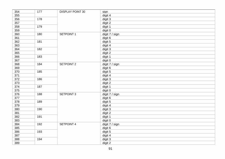
91
41
A push of ENTER from the programming of the display nº29 gives access to the programming of the scaling point nº30 and last of the routine. The ESC key reverts to the previous point. The programming routine is terminated by a press of ENTER after programming the display 30.
"InP-30". Programming the input of point 30. Press repeatedly the
key to increment the active digit value and press the
key to move to the next digit until the display reads the desired value with
sign. The sign is programmed in the most significant digit [ "0" = positive, "-" = negative].
ENTER Validate the entry and advance to the next program step. ESC Return to the programming of the previous point.
"dSP-30". Programming the display of point 30. Use the
(increment digit) and
(move to next digit) procedure to set the value of the display 30 with sign. The most significant digit is used to set the sign ["0"
= positive, "-" = negative].
ENTER Validate the entry, exit from this routine and go to the "-Pro-" stage. ESC Return to the previous point.
354
sign
355 177
digit 4 356 digit 3 357
178 digit 2
358 digit 1 359
179
DISPLAY POINT 30
digit 0 360 digit 7 / sign 361
180 digit 6
362 digit 5 363
181 digit 4
364 digit 3 365
182 digit 2
366 digit 1 367
183
SETPOINT 1
digit 0 368 digit 7 / sign 369
184 digit 6
370 digit 5 371
185 digit 4
372 digit 3 373
186 digit 2
374 digit 1 375
187
SETPOINT 2
digit 0 376 digit 7 / sign 377
188 digit 6
378 digit 5 379
189 digit 4
380 digit 3 381
190 digit 2
382 digit 1 383
191
SETPOINT 3
digit 0 384 digit 7 / sign 385
192 digit 6
386 digit 5 387
193 digit 4
388 digit 3 389
194
SETPOINT 4
digit 2
[41.1] Value of Input 30
[41.2] Value of Display 30
TARE
RESET
LIMIT
MAX/MIN
DATA
ESC
ENTER
M
A X
M I N
HOLD
TARE
1
2
3
4
TARE
RESET
LIMIT
MAX/MIN
DATA
ESC
ENTER
M
A X
M I N
HOLD
TARE
1
2
3
4
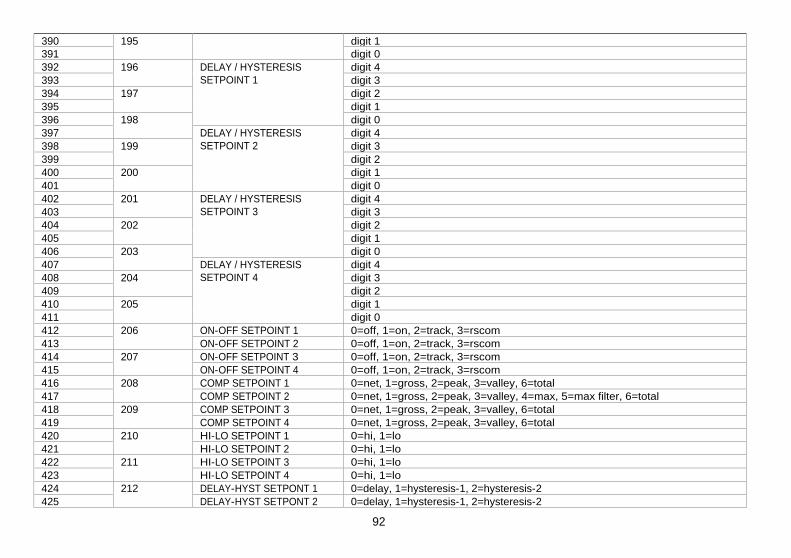
92
42
Figure 42.1 shows the indication corresponding to the access level to the tEACH menu. Press one of the following keys:
ENTER Access to the programming of the first menu parameter. Skip this menu and pass to menu 23 - Display options (page 49).
ESC Exit this menu and return to the -Pro- stage.
This menu allows scaling the display by applying input signal values and keying-in corresponding display values. The decimal point location completes the scaling sequence in the desired units.
Menu 22 tCH-01. Apply input for point 1. The main display reads the actual input signal present at the input connector. Bring the process to the conditions of the first point and press ENTER to take
the displayed input value as the input 1 parameter and go to the programming of the corresponding display.
ESC Cancel this routine and return to the -Pro- stage.
Menu 22 dSP-01. Program display value for point 1. Use the key-in procedure to set the display corresponding to point 1 (
changes
the active digit value,
moves to the next digit to be modified). The sign is programmed in the leftmost digit ["0" = positive, "-" = negative].
ENTER Validate changes and go to the next programming phase. ESC Cancel this routine and return to the -Pro- stage.
[42.1] Access to the Menu
Menu 22 - TEACH (process, load cell and potentiometer)
[42.2] Teach Input Signal 1
[42.3] Value of Display 1
TARE
RESET
LIMIT
MAX/MIN
DATA
ESC
ENTER
M
A X
M I N
HOLD
TARE
1
2
3
4
TARE
RESET
LIMIT
MAX/MIN
DATA
ESC
ENTER
M
A X
M I N
HOLD
TARE
1
2
3
4
TARE
RESET
LIMIT
MAX/MIN
DATA
ESC
ENTER
M
A X
M I N
HOLD
TARE
1
2
3
4
390
digit 1
391 195
digit 0 392 digit 4 393
196 digit 3
394 digit 2 395
197 digit 1
396
DELAY / HYSTERESIS SETPOINT 1
digit 0 397
198 digit 4
398 digit 3 399
199 digit 2
400 digit 1 401
200
DELAY / HYSTERESIS SETPOINT 2
digit 0 402 digit 4 403
201 digit 3
404 digit 2 405
202 digit 1
406
DELAY / HYSTERESIS SETPOINT 3
digit 0 407
203 digit 4
408 digit 3 409
204 digit 2
410 digit 1 411
205
DELAY / HYSTERESIS SETPOINT 4
digit 0 412 ON-OFF SETPOINT 1 0=off, 1=on, 2=track, 3=rscom 413
206 ON-OFF SETPOINT 2 0=off, 1=on, 2=track, 3=rscom
414 ON-OFF SETPOINT 3 0=off, 1=on, 2=track, 3=rscom 415
207 ON-OFF SETPOINT 4 0=off, 1=on, 2=track, 3=rscom
416 COMP SETPOINT 1 0=net, 1=gross, 2=peak, 3=valley, 6=total 417
208 COMP SETPOINT 2 0=net, 1=gross, 2=peak, 3=valley, 4=max, 5=max filter, 6=total
418 COMP SETPOINT 3 0=net, 1=gross, 2=peak, 3=valley, 6=total 419
209 COMP SETPOINT 4 0=net, 1=gross, 2=peak, 3=valley, 6=total
420 HI-LO SETPOINT 1 0=hi, 1=lo 421
210 HI-LO SETPOINT 2 0=hi, 1=lo
422 HI-LO SETPOINT 3 0=hi, 1=lo 423
211 HI-LO SETPOINT 4 0=hi, 1=lo
424 DELAY-HYST SETPONT 1 0=delay, 1=hysteresis-1, 2=hysteresis-2 425
212 DELAY-HYST SETPONT 2 0=delay, 1=hysteresis-1, 2=hysteresis-2

93
43
Menu 22 dECP. Decimal point position. At this step, the decimal point goes in flash. Press the
key to move it to the
right until it gets desired position. If no decimal point is required, it must be located to the rightmost digit as shown in figure 43.1.
ENTER Validate the entry and go to the next step. ESC Cancel this routine and return to the -Pro- stage.
Menu 22 tCH-02. Set input value for point 2. Bring the process to the conditions of the second scaling point. The main display reads the actual input signal present at the input connector. Press ENTER
to take the
displayed input value as the input 2 parameter and go to the programming of the corresponding display.
ESC Cancel this routine and return to the -Pro- stage.
Menu 22 dSP-02. Program display value for point 2. Use the
(change value) and
(change digit) procedure to program the desired value of display 2 with sign. I f you want to accept your changes and exit from the scaling routine with 2 points, press ENTER . If you want to enter the linearization routine press and hold ENTER for 3 seconds.
ESC Cancel this routine and return to the -Pro- stage.
[43.1] Decimal Point
[43.2] Teach Input Signal 2
[43.3] Value of Display 2
TARE
RESET
LIMIT
MAX/MIN
DATA
ESC
ENTER
M
A X
M I N
HOLD
TARE
1
2
3
4
TARE
RESET
LIMIT
MAX/MIN
DATA
ESC
ENTER
M
A X
M I N
HOLD
TARE
1
2
3
4
TARE
RESET
LIMIT
MAX/MIN
DATA
ESC
ENTER
M
A X
M I N
HOLD
TARE
1
2
3
4
426 DELAY-HYST SETPONT 3 0=delay, 1=hysteresis-1, 2=hysteresis-2 427
213 DELAY-HYST SETPONT 4 0=delay, 1=hysteresis-1, 2=hysteresis-2
428 LATCH SETPOINT 1 0=no, 1=yes 429
214 LATCH SETPOINT 2 0=no, 1=yes
430 LATCH SETPOINT 3 0=no, 1=yes 431
215 LATCH SETPOINT 4 0=no, 1=yes
432 BLINK SETPOINT 1 0=LED, 1=LED+blink 433
216 BLINK SETPOINT 2 0=LED, 1=LED+blink
434 BLINK SETPOINT 3 0=LED, 1=LED+blink 435
217 BLINK SETPOINT 4 0=LED, 1=LED+blink
436 TRACK AUTO 0=no, 1=yes 437
218 Nº LINEARIZATION POINTS 2 to 30
438 digit 1 439
219 Nº READINGS SETPOINT MAX
digit 0 440 ANALOG OUTPUT TYPE 0=Vdc, 1=Idc 441
220 ANALOG OUTPUT FILTER 0=off, 1=on
442 sign 443
221 digit 4
444 digit 3 445
222 digit 2
446 digit 1 447
223
ANALOG OUTPUT HI DISPLAY
digit 0 448 sign 449
224 digit 4
450 digit 3 451
225 digit 2
452 digit 1 453
226
ANALOG OUTPUT LO DISPLAY
digit 0 454 digit 4 455
227 digit 3
456 digit 2 457
228 digit 1
458
DIAMETER 1 (VOLUME)
digit 0 459
229 digit 4
460 digit 3 461
230 LENGTH 1 (VOLUME)
digit 2

94
44
From the programming phase of the display 2, press and hold ENTER
for 3 seconds to get access to the linearization routine.
From the point nº3, the progress through the routine is made by pressing the ENTER key after programming each value. At any program step, a press of ESC reverts to the
previous point except for the programming phase of point 3, where the
ESC key returns the meter to the -Pro- stage. To terminate the routine for a number of points less than 30, press and hold ENTER for 3 seconds from the last desired point display.
Bring the process to the conditions of the second scaling point. The main display reads the actual input signal present at the input connector. Press ENTER
to take the
displayed input value as the input 3 parameter and go to the programming of the corresponding display.
ESC Cancel this routine and return to the -Pro- stage.
Menu 21 dSP-03. Program display value for point 3. Press repeatedly the
key to increment the active digit value and press the
key to move to the next digit until the display reads the desired value with sign. The sign is programmed in the most significant digit [ "0" = positive, "-" = negative]. 1. I f you want to validate the data and advance to the next program point, press
ENTER . 2. I f you want to validate the data and terminate the programming routine with three scaling points, press and hold ENTER for 3 seconds. The meter goes to the "-Pro-" stage. Press
ESC
if you want to cancel the programming and return to the "-Pro-" stage.
The same procedure is used to program the rest of the input-display points except that the ESC
key does not return to the "-Pro-" stage, but to the previous point.
[44.1] Teach Input Signal 3
[44.2] Value of Display 3
TARE
RESET
LIMIT
MAX/MIN
DATA
ESC
ENTER
M
A X
M I N
HOLD
TARE
1
2
3
4
TARE
RESET
LIMIT
MAX/MIN
DATA
ESC
ENTER
M
A X
M I N
HOLD
TARE
1
2
3
4
462 digit 1 463
231 digit 0
464 digit 4 465
232 digit 3
466 digit 2 467
233 digit 1
468
DIAMETER 2 (VOLUME)
digit 0 469
234 digit 4
470 digit 3 471
235 digit 2
472 digit 1 473
236
LENGTH 2 (VOLUME)
digit 0 474 digit 4 475
237 digit 3
476 digit 2 477
238 digit 1
478
DIAMETER 3 (VOLUME)
digit 0 479
239 digit 4
480 digit 3 481
240 digit 2
482 digit 1 483
241
LENGTH 3 (VOLUME)
digit 0 484 TANK'S SHAPE 0=no, 1=sphere, 2=cyinder, 3=cylinder+sphere, 4=silo 485
242 DECIMAL POINT (VOLUME) 0=88888, 1=8888.8, 2=888.88, 3=88.888, 4=8.8888
486 EXCITATION 0=24V, 1=10V 487
243 INPUT TYPE 0=process, 1=load cell, 2=Pt100, 3=thermocouple, 4=potentiometer
488 PROCESS TYPE 0=volts, 1=amperes 489
244 THERMOCOUPLE TYPE 0=TCJ, 1=TCK, 2=TCT, 3=TCR, 4=TCS, 5=TCE
490 PROCESS RANGE 0=1V/1mA, 1=10V/20mA 491
245 LOAD CELL RANGE 3=15mV, 2=30mV, 1=60mV, 0=300mV
492 TEMPERATURE SCALE 0=ºC, 1=ºF 493
246 TEMPERATURE RESOLUTION
0=0.1º, 1=1º 494 sign 495
247 digit 1
496
TEMPERATURE OFFSET
digit 0 497
248 DISPLAY DECIMAL POINT 0=88888, 1=8888.8, 2=888.88, 3=88.888, 4=8.8888

A push of ENTER from the programming of the display nº29 gives access to the programming of the scaling point nº30 and last of the routine. The ESC key reverts to the previous point. The programming routine is terminated by a push of ENTER after programming the display 30.
95
45
Menu 22 tCH-30. Set input value for point 30. Bring the process to the conditions of the second scaling point. The main display reads the actual input signal present at the input connector. Press ENTER to take the displayed input value as the input 3 parameter and go to the programming of the corresponding display.
ESC Cancel this routine and return to the -Pro- stage.
"dSP-30". Programming the display of point 30. Use the
(increment digit) and
(move to next digit) procedure to set the value of the display 30 with sign. The most significant digit is used to set the sign ["0" = positive, "-" = negative].
ENTER Validate the entry, exit from this routine and go to the "-Pro-" stage. ESC Return to the previous point.
[41.1] Teach Signal Input 30
[41.2] Value of Display 30
TARE
RESET
LIMIT
MAX/MIN
DATA
ESC
ENTER
M
A X
M I N
HOLD
TARE
1
2
3
4
TARE
RESET
LIMIT
MAX/MIN
DATA
ESC
ENTER
M
A X
M I N
HOLD
TARE
1
2
3
4
498 FILTER P 0 to 9 499
249 FILTER E 0 to 9
500 digit 2 501
250 digit 1
502
READINGS AVERAGE
digit 0 503
251 BRIGHT 0=HI, 1=LO
504 LEFT ZEROS 0=no, 1=yes 505
252 RATE 0=16/s, 1=4/s, 2=1/s
506 ROUND 0=001, 1=002, 2=005, 3=010, 4=020, 5=050, 6=100 507
253 PRINT DATE AND TIME 0=off, 1=on
508 INTEGRATOR 0=no, 1=yes 509
254 TIME BASE 0=second, 1=minute, 2=hour, 3=day
510 digit 3 511
255 digit 2
512 digit 1 513
256
INTEGRAtOR FACTOR
digit 0 514 FACTOR DECIMAL POINT 0=88888, 1=8888.8, 2=888.88, 3=88.888 515
257 TOTALIZER DECIMAL POINT 0=88888888, 1=8888888.8, 2=888888.88, 3=88888.888, 4=8888.8888,
5=888.88888, 6=88.888888, 7=8.8888888 516 sign 517
258 digit 4
518 digit 3 519
259 digit 2
520 digit 1 521
260
LO-CUT
digit 0 522 digit 3 523
261 digit 2
524 digit 1 525
262
SECURITY CODE
digit 0 526 263 SOFT LOCK 1 bit 0 =setpoint 1
bit 1 =setpoint 2 bit 2 =setpoint 3 bit 3 =setpoint 4

96
46
4.2. Integrator
The instrument provides a 8 digit counter (or 7 digits with negative sign) that can be used to accumulate readings in totalizing+batch applications (logic function nº 30 at the rear connector) or to integrate the instantaneous reading using a timebase. The counter is shown on the second display.
-IntEG
23
-oFF-
-IntEG
23
-on-
-IntEG
23
S
tbASE
23
M
tbASE
23
H
tbASE
23
d
tbASE
23
dP
00000.00
00001
FACt
23
00001.
FACt
23
±00.00Lo-Cut
23
The integrator is enabled by setting the option -on- in the menu 23 IntEG. When activated, the logic function nº 30 is inhibited. (NOTE: It is not possible to activate the integrator when the automatic volume calculation option is programmed, see page 57, menu 27 -Vol-).
The value of the integrator appears on the auxiliary display permanently. This allows the instantaneous measurement and the accumulated total be read at the
same time. The second display may show any other variable or be blanked if desired.
The integrator accumulates the reading of the display using a timebase in the following format:
Display Reading x Scale Factor Total(n) = Total(n-1) +
Time Base
As an application example, it is required to show the total fluid quantity that pours out from a drain at a rate of 10 liters per minute. If the instantaneous value is 10.00 and is expressed in lit/min, we must select the timebase in minutes, so the totalizer may show 10.00 lit after one minute, 20.00 lit in two minutes, 600.00 lit in one hour, etc. To read the daily consumption in m3, for instance, we should program a scale factor of 0.001
527 SOFT LOCK 2 bit 0 = input bit 1 = scaling+integrator+volume bit 2 = filters+display+round bit 3 = -
528 SOFT LOCK 3 bit 0 = analog output bit 1 = serial communication output bit 2 = logic inputs bit 3 = direct programming of setpoint values
529
264
SOFT LOCK 4 bit 0 = tare key function bit 1 = - bit 2 = - bit 3 = total lock
530 LOGIC FUNCTION CN2.1 0 to 36 531
265 LOGIC FUNCTION CN2.2 0 to 36
532 LOGIC FUNCTION CN2.3 0 to 36 533
266 LOGIC FUNCTION CN2.4 0 to 36
534 - - 535
267 - -
536 PROTOCOL 1=burster, 2=iso1745, 3=modbus 537
268 BAUD RATE 1=1200, 2=2400, 3=4800, 4=9600, 5=19200
538 ADDRESS UNITS 0 to 9 538
269 ADDRESS TENS 0 to 9
540 TRANSMISSION TO typ9180 0=no, 1=yes 541
270 DELAY RS485 1=30ms, 2=60ms, 3=100ms, 4=300ms, 5=no delay

97
47
The figure 47.1 shows the indication "-IntEG" corresponding to the input stage of the integrator configuration menu.
ENTER To access the integrator configuration. To skip this menu and pass to the next menu.
ESC To cancel this routine and return to the "-Pro-" stage.
This menu allows enabling the integrator option and configuring the function parameters; time base, decimal point, scaling factor and low-cut display. This menu appears only in process and potentiometer configurations.
The first level of this menu offers two choices -on- and -oFF- to enable or disable the integrator respectively. Press the
key to switch the display between the two options to set the desired one. I f the "automatic volume calculation" option is enabled (menu 27 -VoL-) it is not possible to activate the integrator.
ENTER Validate the choice and go to the next program phase. ESC Cancel this routine and return to the "-Pro-" stage.
23 tbASE. Programming the time base. There are four time bases : -S- seconds, -M- minutes, -H- hours and -d- days. Use
to shift around the available options until the display shows the indication corresponding to the desired time base.
ENTER Validate the choice and go to the next program phase. ESC Cancel this routine and return to the "-Pro-" stage.
[47.1] Access to the menu
Menu 23 - INTEGRATOR (for process and potentiometer)
[47.2] ON-OFF Selection
[47.3] Time Base
TARE
RESET
LIMIT
MAX/MIN
DATA
ESC
ENTER
M
A X
M I N
HOLD
TARE
1
2
3
4
TARE
RESET
LIMIT
MAX/MIN
DATA
ESC
ENTER
M
A X
M I N
HOLD
TARE
1
2
3
4
TARE
RESET
LIMIT
MAX/MIN
DATA
ESC
ENTER
M
A X
M I N
HOLD
TARE
1
2
3
4
DINAMIC VARIABLES (READ ONLY) MODBUS Variable Description Format
276 Peak Value Internal peak value Long (2 word) 278 Valley value Internal valley value Long (2 word) 280 Tare value Internal Tare Long (2 word) 282 Batch counter Internal batch counter Integer (1 word) 285 Totalizer Internal totalizer counter Float (2 word) 287 Net value Net value on display (with filters, round and hold) Long (2 word) 289 Gross value Gross value on display (with filters, round and hold) Long (2 word) 291 Input signal value Input signal value on display (with filters and hold) Float (2 word) 293 Setpoint1 Setpoint 1 value Long (2 word) 295 Setpoint2 Setpoint 2 value Long (2 word) 297 Setpoint3 Setpoint 3 value Long (2 word) 299 Setpoint4 Setpoint 4 value Long (2 word) 301 Batch Batch Value on display (with filters and hold) Integer (1 word) 302 Total Total Value on display (with filters and hold) Long (2 word) 304 Peak Peak Value on display (with filters and hold) Long (2 word) 306 Valley Valley Value on display (with filters and hold) Long (2 word) 308 Net Internal net value, without filter nor round Long (2 word) 310 Gross Internal gross value, without filter nor round Long (2 word) 312 Input Input signal value, no filter Long (2 word) 314 Net round Net value with filters and round Long (2 word) 316 Gross round Gross value with filters and round Long (2 word) 318 State of the setpoints and the
logic inputs (0=deactivated, 1=activated)
bit 0 = setpoint 1 status bit 1 = setpoint 2 status bit 2 = setpoint 3 status bit 3 = setpoint 4 status bit 4 = logic input 1 status bit 5 = logic input 2 status bit 6 = logic input 4 status bit 7 = logic input 5 status
Byte

98
48
The totalizer decimal point is programmed in the second display and can be located in any of its 8 digits. In this step, the main display shows the indication "dP" and the second display shows the decimal point in flash. Press repeatedly the
key to
move it to the desired location. I f no decimal point is required, it must be placed to the right of the least significant digit, see figure 48.1.
ENTER Validate the choice and go to the next program phase. ESC Cancel this routine and return to the "-Pro-" stage.
"23 FACt". Programming the scale factor. Press repeatedly the key to increment the active digit and press the key to move to the next digit to the right until the desired scale factor value is completed on the display. A press of ENTER
to validate the entry makes the decimal point go in flash. The factor decimal point position is independent from the one of the display, so it is possible to program any value within the range 0.0001 to 09999. It is not possible to set the scale factor to 0.
ENTER Validate the entry and go to the next program phase. ESC Cancel this routine and return to the "-Pro-" stage.
"Low-Cut" is the value below which the display is not added to the totalizer. Press repeatedly the key to increment the active digit and press the key to move to the next digit to be modified until desired value is completed on the display. The leftmost digit is used to set the sign ["0" = positive, "-" = negative].
ENTER Validate the entry, exit from this routine and go to the "-Pro-" stage. ESC Cancel this routine and return to the "-Pro-" stage.
[48.1] Decimal Point
[48.2] Scale Factor
[48.3] Low-Cut Display
TARE
RESET
LIMIT
MAX/MIN
DATA
ESC
ENTER
M
A X
M I N
HOLD
TARE
1
2
3
4
TARE
RESET
LIMIT
MAX/MIN
DATA
ESC
ENTER
M
A X
M I N
HOLD
TARE
1
2
3
4
TARE
RESET
LIMIT
MAX/MIN
DATA
ESC
ENTER
M
A X
M I N
HOLD
TARE
1
2
3
4
MODBUS Variable Description Format
318 Options installed (0=not installed, 1=installed)
bit 0 = 2RE bit 1 = 4RE bit 2 = RS2 bit 3 = RS4 bit 4 = - bit 5 = BCD bit 6 = ANA bit 7 = -
Byte
digit 0 (LSB) Byte 319 digit 1 Byte digit 2 Byte 320 digit 3 Byte digit 4 Byte 321 digit 5 (MSB) Byte LED's Byte 322
Digits of the main display
- Byte digit 0 (LSB) Byte 323 digit 1 Byte digit 2 Byte 324 digit 3 Byte digit 4 Byte 325 digit 5 Byte digit 6 Byte 326
Digits of the auxiliary display
digit 7 (MSB) Byte Units Byte 327 Tenth Byte Hundreds Byte 328 M
Byte
Version
b
Byte 329 Run/Prog mode 0=run, 1=prog Byte Display overflow (internal) 0=no, 1=yes Byte 330 Input overflow 0=no, 1=yes Byte Display overflow 0=no, 1=yes Byte 331 Totalizer overflow 0=no, 1=yes Byte