TXS 3800 Manual - sencore.com
57
July 2021 8226 www.sencore.com | 1.605.978.4600 Revision 1.0 TXS 3800 ATSC 3.0 Transcoder User Manual
Transcript of TXS 3800 Manual - sencore.com
July 2021 8226 www.sencore.com | 1.605.978.4600 Revision 1.0
TXS 3800
ATSC 3.0 Transcoder
User Manual

TXS 3800 – User Manual
Page 2 (57)
Copyright © 2021 Sencore, Inc. All rights reserved. 3200 Sencore Drive, Sioux Falls, SD USA www.sencore.com This publication contains confidential, proprietary, and trade secret information. No part of this document may be copied, photocopied, reproduced, translated, or reduced to any machine-readable or electronic format without prior written permission from Sencore. Information in this document is subject to change without notice and Sencore Inc. assumes no responsibility or liability for any errors or inaccuracies. Sencore, Sencore Inc., and the Sencore logo are trademarks or registered trademarks in the United States and other countries. All other products or services mentioned in this document are identified by the trademarks, service marks, or product names as designated by the companies who market those products. Inquiries should be made directly to those companies. This document may also have links to third-party web pages that are beyond the control of Sencore. The presence of such links does not imply that Sencore endorses or recommends the content on those pages. Sencore acknowledges the use of third-party open source software and licenses in some Sencore products. This freely available source code can be obtained by contacting Sencore Inc.
About Sencore Sencore is an engineering leader in the development of high-quality signal transmission solutions for the broadcast, cable, satellite, IPTV, telecommunications, and professional audio/video markets. The company’s world-class portfolio includes video delivery products, system monitoring and analysis solutions, and test and measurement equipment, all designed to support system interoperability and backed by best-in-class customer support. Sencore meets the rapidly changing needs of modern media by ensuring the efficient delivery of high-quality video from the source to the home. For more information, visit www.sencore.com.

TXS 3800 – User Manual
Page 3 (57)
Revision History
Date (MM/DD/YYYY) Version Description Author
07/07/2021 1.0 Initial Release JDN

TXS 3800 – User Manual
Page 4 (57)
Safety Instructions
• Read these instructions
• Keep these instructions
• Heed all warnings
• Follow all instructions
• Do not use this apparatus near water
• Clean only with dry cloth
• Do not block any ventilation openings. Install in accordance with the manufacturer’s instructions
• Do not install near any heat sources such as radiators, heat registers, stoves, or other apparatus (including amplifiers) that produce heat
• Do not defeat the safety purpose of the polarized or grounding-type plug. A polarized plug has two blades with one wider than the other. A grounding type plug has two blades and a third grounding prong. The wide blade or the third prong is provided for your safety. If the provided plug does not fit into your outlet, consult an electrician for replacement of the obsolete outlet.
• Protect the power cord from being walked on or pinched particularly at plugs, convenience receptacles, and the point where they exit from the apparatus.
• Only use attachments/accessories specified by the manufacturer.
• Unplug this apparatus during lightning storms or when unused for long periods of time.
• Refer all servicing to qualified service personnel. Servicing is required when the apparatus has been damaged in any way, such as power-supply cord or plug is damaged, liquid has been spilled or objects have fallen into the apparatus, the apparatus has been exposed to rain or moisture, does not operate normally, or has been dropped.
• Do not expose this apparatus to dripping or splashing and ensure that no objects filled with liquids, such as vases, are placed on the apparatus.
• To completely disconnect this apparatus from the AC Mains, disconnect the power supply cord plug from the AC receptacle.
• The mains plug of the power supply cord shall remain readily operable.
• Damage Requiring Service: Unplug this product from the wall outlet and refer servicing to qualified service personnel under the following conditions:
o When the power-supply cord or plug is damaged. o If liquid has been spilled, or objects have fallen into the product. o If the product has been exposed to rain or water. o If the product does not operate normally by following the operating
instructions. Adjust only those controls that are covered by the operating instructions as an improper adjustment of the controls may result in damage and will often require extensive work by a qualified technician to restore the product to its normal operation.
o If the product has been dropped or damaged in any way. o The product exhibits a distinct change in performance.
• Replacement Parts: When replacement parts are required, be sure the service technician uses replacement parts specified by Sencore, or parts having the same operating characteristics as the original parts. Unauthorized part substitutions made may result in fire, electric shock or other hazards.

TXS 3800 – User Manual
Page 5 (57)
SAFETY PRECAUTIONS
There is always a danger present when using electronic equipment.
Unexpected high voltages can be present at unusual locations in defective equipment and signal distribution systems. Become familiar with the equipment that you are working with and observe the following safety precautions.
• Every precaution has been taken in the design of your product to ensure that it is as safe as possible. However, safe operation depends on you the operator.
• Always be sure your equipment is in good working order. Ensure that all points of connection are secure to the chassis and that protective covers are in place and secured with fasteners.
• Never work alone when working in hazardous conditions. Always have another person close by in case of an accident.
• Always refer to the manual for safe operation. If you have a question about the application or operation email [email protected]
• WARNING – To reduce the risk of fire or electrical shock never allow your equipment to be exposed to water, rain or high moisture environments. If exposed to a liquid, remove power safely (at the breaker) and send your equipment to be serviced by a qualified technician.
• To reduce the risk of shock the power supply must be connected to a mains socket outlet with a protective earthing connection.
• For the mains plug the main disconnect and should remain readily accessible and operable at all times.
• When utilizing DC power supply, the power supply MUST be used in conjunction with an over-current protective device rated at 50 V, 5 A, type: Slow-blo, as part of battery-supply circuit.
• To reduce the risk of shock and damage to equipment, it is recommended to ground the unit to the installation’s rack, the vehicle’s chassis, the battery’s negative terminal, and/or earth ground.
Warning: Changes or modifications to this unit not expressly approved by the
party responsible for compliance could void the user’s authority to operate the equipment.
TXS 3800 – User Manual
Page 6 (57)
Package Contents The following is a list of the items that are included:
1. TXS 3800 Chassis 2. TXS 3800 Software 3. 2x AC Power Cables 4. Quick Start Guide
If any of these items were omitted from the packaging please email
[email protected] to obtain a replacement.

TXS 3800 – User Manual
Page 7 (57)
Table of Contents
SECTION 1 OVERVIEW .............................................................................................................................. 9
1.1 PRODUCT INTRODUCTION .................................................................................................................. 10 1.2 FRONT PANEL OVERVIEW .................................................................................................................. 10 1.3 REAR PANEL OVERVIEW .................................................................................................................... 11
SECTION 2 INSTALLATION ...................................................................................................................... 12
2.1 RACK INSTALLATION ......................................................................................................................... 13 2.2 AC DUAL REDUNDANT POWER CONNECTIONS....................................................................................... 13 2.3 MAINTENANCE ................................................................................................................................ 13 2.4 NETWORK SETUP VIA KVM ............................................................................................................... 13
SECTION 3 WEB-INTERFACE OPERATION ................................................................................................ 14
3.1 TXS 3800 WEB INTERFACE OVERVIEW ................................................................................................ 15 3.1.1 Logging into the TXS 3800 Web Interface............................................................................... 15 3.1.2 Buttons and Status Indicators ................................................................................................. 15
3.2 TRANSCODER PANEL ......................................................................................................................... 16 3.2.1 Configuring Active Inputs ........................................................................................................ 16
3.2.1.1 ATSC 3.0 RF Input .......................................................................................................................... 17 3.2.1.2 ATSC 3.0 IP Inputs ......................................................................................................................... 18
3.2.2 Configuring Processing and Service Selection ......................................................................... 19 3.2.2.1 Service Configuration .................................................................................................................... 20 3.2.2.2 Video Configuration ...................................................................................................................... 22 3.2.2.3 Audio Decoder Configuration........................................................................................................ 23 3.2.2.4 Audio Encoder Configuration ........................................................................................................ 25 3.2.2.5 Advanced Configuration ................................................................................................................ 28
3.2.3 Configuring Outputs ............................................................................................................... 29 3.2.3.1 Configuring MPEG/IP Outputs....................................................................................................... 29
3.3 ADMIN PANEL ................................................................................................................................. 32 3.3.1 Chassis Statistics ..................................................................................................................... 33 3.3.2 Unit Alias ................................................................................................................................. 33 3.3.3 Changing Unit Password ......................................................................................................... 33 3.3.4 Profiles .................................................................................................................................... 34 3.3.5 Diagnostics.............................................................................................................................. 35 3.3.6 Updating the TXS 3800 ........................................................................................................... 35 3.3.7 Applying Software Updates .................................................................................................... 35 3.3.8 Configuring ATSC 3.0 RF Module ............................................................................................ 37 3.3.9 Rollback Software Updates ..................................................................................................... 38 3.3.10 Reboot Unit ........................................................................................................................ 38 3.3.11 Reset to Defaults ................................................................................................................ 39 3.3.12 Configure Unit Networks .................................................................................................... 39 3.3.13 Software Support Agreements ........................................................................................... 41 3.3.14 Date/Time .......................................................................................................................... 41 3.3.15 SNMP Community .............................................................................................................. 42 3.3.16 SNMP Trap Manager .......................................................................................................... 43 3.3.17 Syslog.................................................................................................................................. 43
3.4 REPORTING PANEL ........................................................................................................................... 44 3.4.1 Active Alarms .......................................................................................................................... 44 3.4.2 Event Logs ............................................................................................................................... 45 3.4.3 Configuring the Logs ............................................................................................................... 45
3.5 ABOUT PANEL ................................................................................................................................. 47

TXS 3800 – User Manual
Page 8 (57)
SECTION 4 APPENDICES.......................................................................................................................... 49
APPENDIX A – ACRONYMS AND GLOSSARY ....................................................................................... 50
APPENDIX B – ERROR AND EVENT LIST .............................................................................................. 51
APPENDIX C – SPECIFICATIONS ......................................................................................................... 52
APPENDIX D – OPEN SOURCE SOFTWARE .......................................................................................... 54
APPENDIX E – WARRANTY ................................................................................................................ 56
APPENDIX F – SUPPORT AND CONTACT INFORMATION ................................................................... 56

TXS 3800 – User Manual
Page 9 (57)
Section 1 Overview
Introduction
This section includes the following topics:
1.1 PRODUCT INTRODUCTION .................................................................................................................. 10 1.2 FRONT PANEL OVERVIEW .................................................................................................................. 10 1.3 REAR PANEL OVERVIEW .................................................................................................................... 11

TXS 3800 – User Manual
Page 10 (57)
1.1 Product Introduction
Sencore’s TXS 3800 ATSC 3.0 transcoder enables users to process up to 4 channels in a 1RU platform. This transcoder is perfectly suited for retransmission of ATSC 3.0 on existing cable, IPTV and satellite systems.
The TXS 3800 transcoder includes an ATSC 3.0 RF input for receiving the next-generation RF signal. Tune to multiple PLPs and transcode up to 4 services. Processed services are output via MPEG/IP. The configuration is done using the intuitive web GUI or through APIs like Rest and SNMP.
Every TXS 3800 ships with the software suite pre-loaded on appropriate hardware.
Input Capabilites:
✓ 1x ATSC 3.0 RF input, multiple PLPs, 1x tuner (TXS 38020)
✓ 1x ATSC 3.0 RF input, multiple PLPs, 12x tuners (TXS 38021)
✓ ATSC 3.0 IP Inputs
o 2 per transcoder
Transcoder Output Video Codecs:
✓ MPEG-2
✓ H.264
Transcoder Output Audio Codecs:
✓ MPEG-1/MPEG-2
✓ AAC
✓ AC-3/E-AC-3
Output Capabilities:
✓ MPEG/IP Output Streams
o 2 per trancoder
Power Supply:
✓ 120/240V Switching Power Supplies
✓ Redundant power design utilizing two independent cables
1.2 Front Panel Overview
The TXS 3800 product is a software-based solution; designed to run on a PC server chassis. Initial network configuration is done with keyboard, monitor, and mouse. Once the IP is configured all operation and setup is via web-interface over a network.
To obtain the associated documentation from the server manufacturer or detailed
information regarding front of chassis indicator lights email [email protected]
TXS 3800 – User Manual
Page 11 (57)
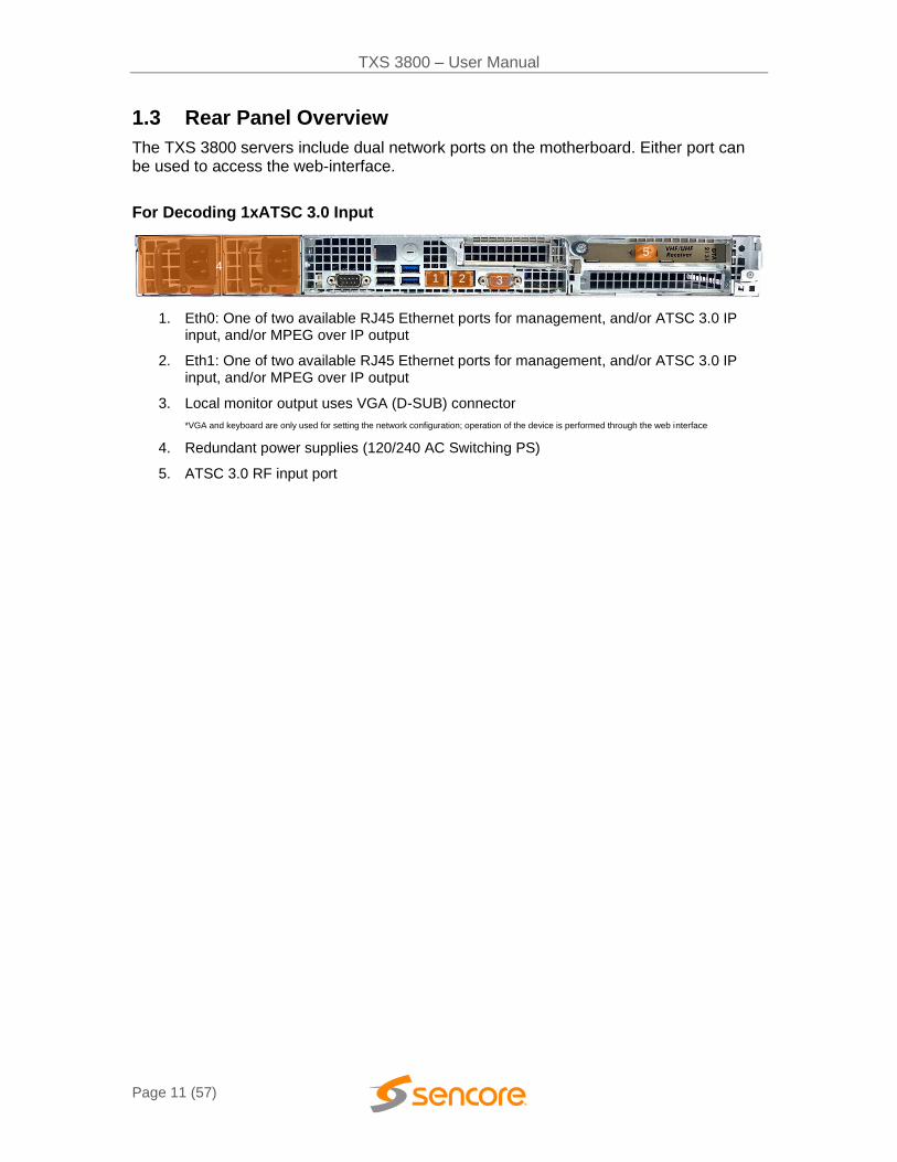
1.3 Rear Panel Overview
The TXS 3800 servers include dual network ports on the motherboard. Either port can be used to access the web-interface.
For Decoding 1xATSC 3.0 Input
1. Eth0: One of two available RJ45 Ethernet ports for management, and/or ATSC 3.0 IP input, and/or MPEG over IP output
2. Eth1: One of two available RJ45 Ethernet ports for management, and/or ATSC 3.0 IP input, and/or MPEG over IP output
3. Local monitor output uses VGA (D-SUB) connector
*VGA and keyboard are only used for setting the network configuration; operation of the device is performed through the web interface
4. Redundant power supplies (120/240 AC Switching PS)
5. ATSC 3.0 RF input port
1 2 3
1
4
5
1

TXS 3800 – User Manual
Page 12 (57)
Section 2 Installation
Introduction
This section includes the following topics:
2.1 RACK INSTALLATION ......................................................................................................................... 13 2.2 AC DUAL REDUNDANT POWER CONNECTIONS....................................................................................... 13 2.3 MAINTENANCE ................................................................................................................................ 13 2.4 NETWORK SETUP VIA KVM ............................................................................................................... 13
TXS 3800 – User Manual
Page 13 (57)
2.1 Rack Installation
The TXS 3800 software product runs on Supermicro brand hardware. Please consult the Supermicro SC514 Series Revision 1.0 user manual for complete detail on the rack installation and power cable connections.
https://www.supermicro.com/manuals/chassis/1U/SC514.pdf
2.2 AC Dual Redundant Power Connections
The Dual, Redundant power supplies allow the TXS 3800 to be powered with 120V or 240V systems. The power supply will automatically detect the system it is connected to. To connect the power, use the following steps:
1. Locate the AC power cords that are included.
2. Plug the female end of the power cords (end with no prongs) into the back of the unit.
3. Locate a protected outlet (usually inside of the rack) to plug the male ends of the power cables into.
2.3 Maintenance
Refer to the server manufacturer documentation for detailed information regarding server hardware maintenance.
To request a copy of the latest TXS 3800 software or release notes from Sencore
email [email protected]
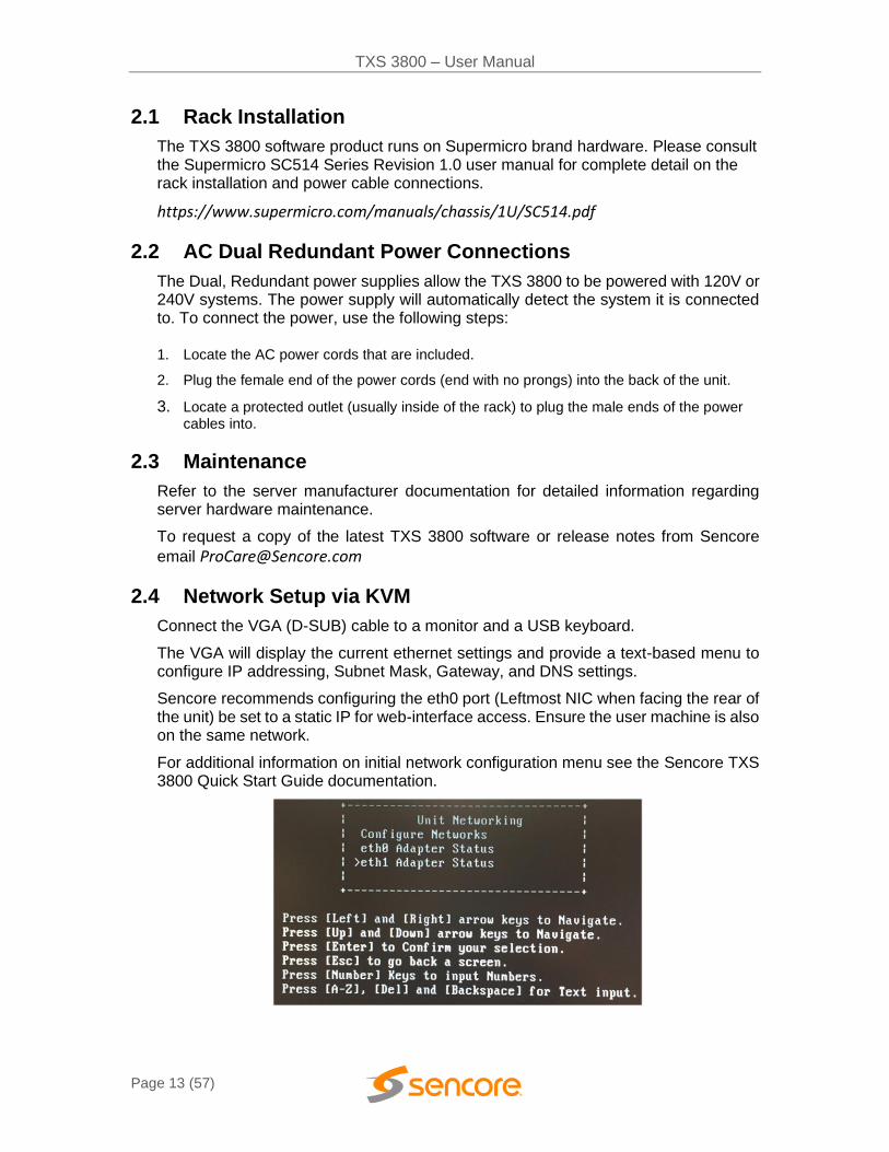
2.4 Network Setup via KVM
Connect the VGA (D-SUB) cable to a monitor and a USB keyboard.
The VGA will display the current ethernet settings and provide a text-based menu to configure IP addressing, Subnet Mask, Gateway, and DNS settings.
Sencore recommends configuring the eth0 port (Leftmost NIC when facing the rear of the unit) be set to a static IP for web-interface access. Ensure the user machine is also on the same network.
For additional information on initial network configuration menu see the Sencore TXS 3800 Quick Start Guide documentation.

TXS 3800 – User Manual
Page 14 (57)
Section 3 Web-Interface Operation
Introduction
This section includes the following topics:
3.1 TXS 3800 WEB INTERFACE OVERVIEW ................................................................................................ 15 3.2 TRANSCODER PANEL ......................................................................................................................... 16 3.3 ADMIN PANEL ................................................................................................................................. 32 3.4 REPORTING PANEL ........................................................................................................................... 44 3.5 ABOUT PANEL ................................................................................................................................. 47
TXS 3800 – User Manual
Page 15 (57)
3.1 TXS 3800 Web Interface Overview
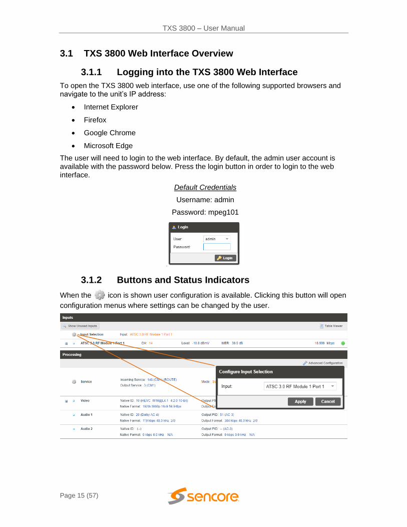
3.1.1 Logging into the TXS 3800 Web Interface
To open the TXS 3800 web interface, use one of the following supported browsers and navigate to the unit’s IP address:
• Internet Explorer
• Firefox
• Google Chrome
• Microsoft Edge
The user will need to login to the web interface. By default, the admin user account is available with the password below. Press the login button in order to login to the web interface.
Default Credentials
Username: admin
Password: mpeg101
3.1.2 Buttons and Status Indicators
When the icon is shown user configuration is available. Clicking this button will open
configuration menus where settings can be changed by the user.

TXS 3800 – User Manual
Page 16 (57)
When the icon is shown additional status information can be viewed. Click this button will expand the menu to display the additional status information. All text in status menus shown in ORANGE are user configurable settings. Text shown in BLUE is not user configurable and is strictly a status or value. To minimize the status windows again click
the icon.
Status in the TXS 3800 web interface is shown with LED status indicators:
Green LED Status is good. No errors are present and function is operating normally.
Red LED Status indicates function is affected by active error. To view the errors, navigate to Alarms panel to view Active Errors.
Grey LED Status is inactive. Function is currently disabled or unavailable.
3.2 Transcoder Panel
The Transcoder panel of the TXS 3800 web interface is used to configure the unit to transcode and what output format to use. Each functional piece has a heading: Inputs, Processing, and Outputs sections are listed from the top down.
3.2.1 Configuring Active Inputs
This menu allows the user to configure the active input. Input options include ATSC 3.0 RF Port 1, ATSC 3.0 IP Input 1, and ATSC 3.0 IP Input 2.

TXS 3800 – User Manual
Page 17 (57)
Each ATSC 3.0 IP Input can be configured to use either Eth0 or Eth1 ports on the back of the chassis.
ATSC 3.0 RF will use the only available RF port on the installed RF card.
Setting Range Description
Input None
ATSC 3.0 RF Module 1 Port 1
ATSC 3.0 IP Input 1
ATSC 3.0 IP Input 2
This setting allows the user to select the input mode.
3.2.1.1 ATSC 3.0 RF Input
Once the TXS 3800 is locked on an ATSC 3.0 RF signal, the indicator light on the right will turn green, and the received bitrate is displayed. RF Level, MER, Pre-LDPC BER, Post-BCH FER are shown under Status. Statistics are displayed representing Relock Counts and FEC Block Errors in the RF stream. These counters can be manually reset using the Reset Counters button. The last reset of these error counters is displayed in a date/time format. The desired status of an individual PLP ID is selectable under the PLP & Subframe Status. You can see the Number of PLPs and Subframes in the RF stream. When a PLP is selected, that PLP’s Modulation, Code rates, FEC Type, and Size will populate the PLP Subframe Status. See section 3.3.8 for configuring the ATSC 3.0 RF card.
TXS 3800 – User Manual
Page 18 (57)
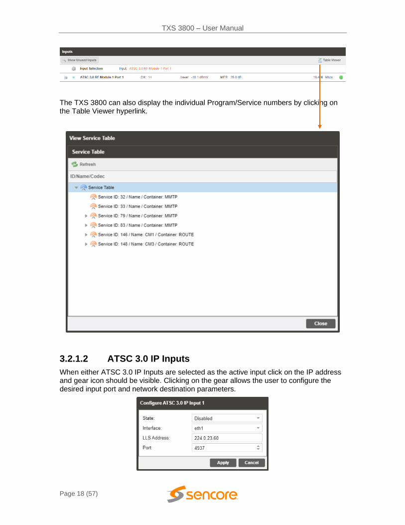
The TXS 3800 can also display the individual Program/Service numbers by clicking on the Table Viewer hyperlink.
3.2.1.2 ATSC 3.0 IP Inputs
When either ATSC 3.0 IP Inputs are selected as the active input click on the IP address and gear icon should be visible. Clicking on the gear allows the user to configure the desired input port and network destination parameters.

TXS 3800 – User Manual
Page 19 (57)
Setting Range Description
State Enabled
Disabled
This setting allows the user to enable or disable these input stream settings
Interface eth0
eth1
The physical connector on the TXS 3800 chassis that will be used to receive the input
LLS Address 224.0.0.0 – 239.255.255.255 LLS is the Low-Level Signalling table that is the index for the location of the rest of the data related to this ATSC 3.0 stream. The LLS Address by default is 224.0.23.60. This address field must point to the LLS for the stream to be received
Port 0 - 65535 This is the UDP port the source device is sending to. The default for LLS is 4937
Once the TXS 3800 is locked onto an ATSC 3.0 IP input signal, the indicator light on the right will turn green, and the received bitrate is displayed.
3.2.2 Configuring Processing and Service Selection
This menu allows the user to configure which service the TXS 3800 will transcode, video processing settings, and audio processing settings.
When the TXS 3800 begins processing a service, the Video dropdown status will report HDR wide color gamut metadata and closed captioning.

TXS 3800 – User Manual
Page 20 (57)
3.2.2.1 Service Configuration
In this menu, the active input can be assigned to the service selection menu for processing via PID-based selection. Once a Service is selected, the selected service’s PIDs will display under the Configure PIDs section.
TXS 3800 – User Manual
Page 21 (57)
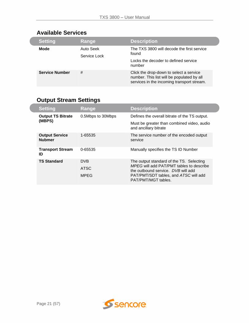
Available Services
Setting Range Description
Mode Auto Seek
Service Lock
The TXS 3800 will decode the first service found
Locks the decoder to defined service number
Service Number #
Click the drop-down to select a service number. This list will be populated by all services in the incoming transport stream.
Output Stream Settings
Setting Range Description
Output TS Bitrate (MBPS)
0.5Mbps to 30Mbps
Defines the overall bitrate of the TS output.
Must be greater than combined video, audio and ancillary bitrate
Output Service Nubmer
1-65535
The service number of the encoded output service
Transport Stream ID
0-65535 Manually specifies the TS ID Number
TS Standard DVB
ATSC
MPEG
The output standard of the TS. Selecting MPEG will add PAT/PMT tables to describe the outbound service. DVB will add PAT/PMT/SDT tables, and ATSC will add PAT/PMT/MGT tables.

TXS 3800 – User Manual
Page 22 (57)
3.2.2.2 Video Configuration
This menu is used to configure Video settings for the transcoding process.
Setting Range Description
Codec MPEG-2
H.264
Defines which video codec the TXS 3800 will use to encode the video
Format Mode Auto
Manual
Auto: the TXS 3800 will match the output video format to the input video format.
Manual: the user defines the video format the TXS 3800 will output
Manual Format Video format the TXS 3800 will output
Aspect Ratio Auto
4:3
16:9
Defines aspect ratio of the video the transcoder will output. When set to Auto, the TXS 3800 will match the output aspect ratio to the input aspect ratio. Otherwise, the Aspect Ratio is specified as 4:3 or 16:9.
Max Bitrate (Mbps) 0.5Mbps to 18Mbps Defines the video bitrate of the transcoded service
TXS 3800 – User Manual
Page 23 (57)
Closed GOP Enabled
Disabled
When enabled, B and P frames will only be able to reference frames inside their own GOP
GOP Size 12 ~ 48
Specifies the number of video frames in the GOP
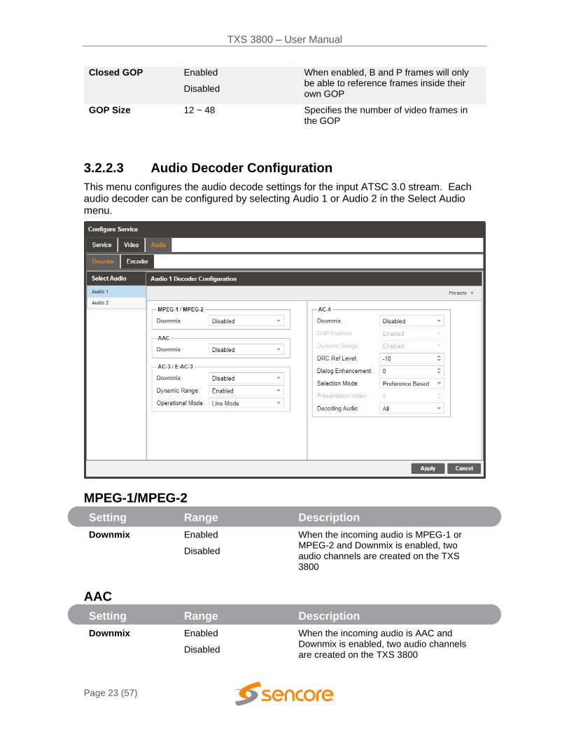
3.2.2.3 Audio Decoder Configuration
This menu configures the audio decode settings for the input ATSC 3.0 stream. Each audio decoder can be configured by selecting Audio 1 or Audio 2 in the Select Audio menu.
MPEG-1/MPEG-2
Setting Range Description
Downmix Enabled
Disabled
When the incoming audio is MPEG-1 or MPEG-2 and Downmix is enabled, two audio channels are created on the TXS 3800
AAC
Setting Range Description
Downmix Enabled
Disabled
When the incoming audio is AAC and Downmix is enabled, two audio channels are created on the TXS 3800
TXS 3800 – User Manual
Page 24 (57)
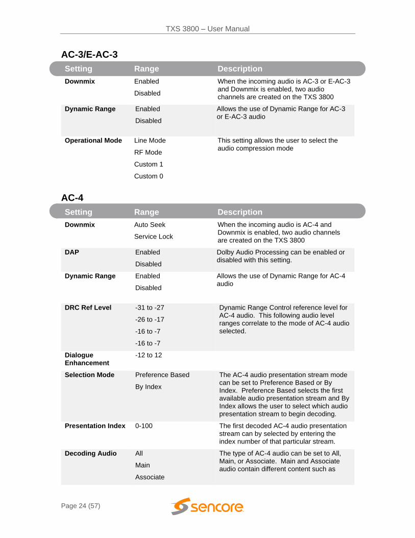
AC-3/E-AC-3
Setting Range Description
Downmix Enabled
Disabled
When the incoming audio is AC-3 or E-AC-3 and Downmix is enabled, two audio channels are created on the TXS 3800
Dynamic Range Enabled
Disabled
Allows the use of Dynamic Range for AC-3 or E-AC-3 audio
Operational Mode Line Mode
RF Mode
Custom 1
Custom 0
This setting allows the user to select the audio compression mode
AC-4
Setting Range Description
Downmix Auto Seek
Service Lock
When the incoming audio is AC-4 and Downmix is enabled, two audio channels are created on the TXS 3800
DAP Enabled
Disabled
Dolby Audio Processing can be enabled or disabled with this setting.
Dynamic Range Enabled
Disabled
Allows the use of Dynamic Range for AC-4 audio
DRC Ref Level -31 to -27
-26 to -17
-16 to -7
-16 to -7
Dynamic Range Control reference level for AC-4 audio. This following audio level ranges correlate to the mode of AC-4 audio selected.
Dialogue Enhancement
-12 to 12
Selection Mode Preference Based
By Index
The AC-4 audio presentation stream mode can be set to Preference Based or By Index. Preference Based selects the first available audio presentation stream and By Index allows the user to select which audio presentation stream to begin decoding.
Presentation Index 0-100 The first decoded AC-4 audio presentation stream can by selected by entering the index number of that particular stream.
Decoding Audio All
Main
Associate
The type of AC-4 audio can be set to All, Main, or Associate. Main and Associate audio contain different content such as
TXS 3800 – User Manual
Page 25 (57)
music, effects, scene descriptions or director’s comments.
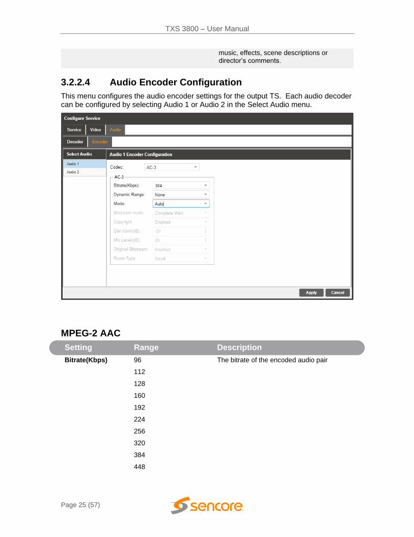
3.2.2.4 Audio Encoder Configuration
This menu configures the audio encoder settings for the output TS. Each audio decoder can be configured by selecting Audio 1 or Audio 2 in the Select Audio menu.
MPEG-2 AAC
Setting Range Description
Bitrate(Kbps) 96
112
128
160
192
224
256
320
384
448
The bitrate of the encoded audio pair
TXS 3800 – User Manual
Page 26 (57)
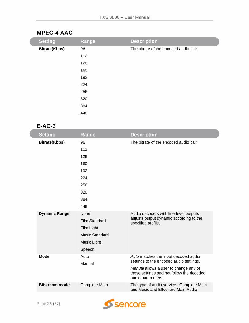
MPEG-4 AAC
Setting Range Description
Bitrate(Kbps) 96
112
128
160
192
224
256
320
384
448
The bitrate of the encoded audio pair
E-AC-3
Setting Range Description
Bitrate(Kbps) 96
112
128
160
192
224
256
320
384
448
The bitrate of the encoded audio pair
Dynamic Range None
Film Standard
Film Light
Music Standard
Music Light
Speech
Audio decoders with line-level outputs adjusts output dynamic according to the specified profile.
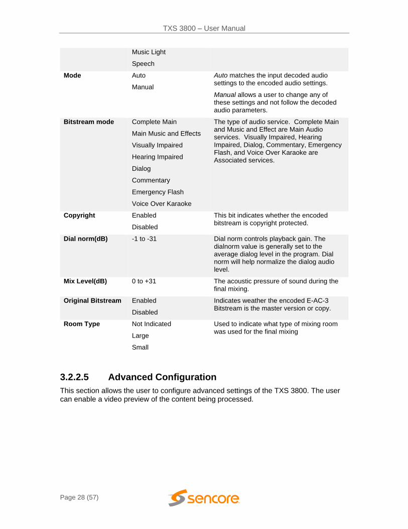
Mode Auto
Manual
Auto matches the input decoded audio settings to the encoded audio settings.
Manual allows a user to change any of these settings and not follow the decoded audio parameters.
Bitstream mode Complete Main The type of audio service. Complete Main and Music and Effect are Main Audio

TXS 3800 – User Manual
Page 27 (57)
Main Music and Effects
Visually Impaired
Hearing Impaired
Dialog
Commentary
Emergency Flash
Voice Over Karaoke
services. Visually Impaired, Hearing Impaired, Dialog, Commentary, Emergency Flash, and Voice Over Karaoke are Associated services.
Copyright Enabled
Disabled
This bit indicates whether the encoded bitstream is copyright protected.
Dial norm(dB) -1 to -31 Dial norm controls playback gain. The dialnorm value is generally set to the average dialog level in the program. Dial norm will help normalize the dialog audio level.
Mix Level(dB) 0 to +31 The acoustic pressure of sound during the final mixing.
Original Bitstream Enabled
Disabled
Indicates weather the encoded E-AC-3 Bitstream is the master version or copy.
Room Type Not Indicated
Large
Small
Used to indicate what type of mixing room was used for the final mixing
AC-3
Setting Range Description
Bitrate(Kbps) 96
112
128
160
192
224
256
320
384
448
The bitrate of the encoded audio pair
Dynamic Range None
Film Standard
Film Light
Music Standard
Audio decoders with line-level outputs adjusts output dynamic according to the specified profile.
TXS 3800 – User Manual
Page 28 (57)
Music Light
Speech
Mode Auto
Manual
Auto matches the input decoded audio settings to the encoded audio settings.
Manual allows a user to change any of these settings and not follow the decoded audio parameters.
Bitstream mode Complete Main
Main Music and Effects
Visually Impaired
Hearing Impaired
Dialog
Commentary
Emergency Flash
Voice Over Karaoke
The type of audio service. Complete Main and Music and Effect are Main Audio services. Visually Impaired, Hearing Impaired, Dialog, Commentary, Emergency Flash, and Voice Over Karaoke are Associated services.
Copyright Enabled
Disabled
This bit indicates whether the encoded bitstream is copyright protected.
Dial norm(dB) -1 to -31 Dial norm controls playback gain. The dialnorm value is generally set to the average dialog level in the program. Dial norm will help normalize the dialog audio level.
Mix Level(dB) 0 to +31 The acoustic pressure of sound during the final mixing.
Original Bitstream Enabled
Disabled
Indicates weather the encoded E-AC-3 Bitstream is the master version or copy.
Room Type Not Indicated
Large
Small
Used to indicate what type of mixing room was used for the final mixing
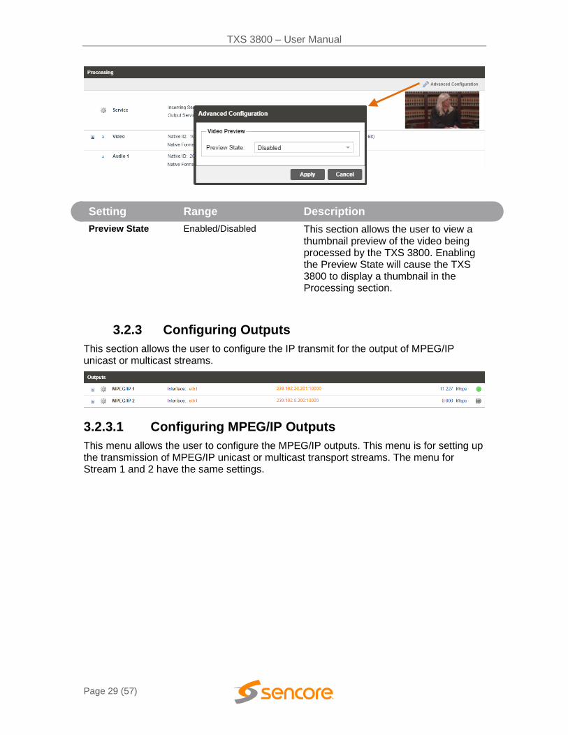
3.2.2.5 Advanced Configuration
This section allows the user to configure advanced settings of the TXS 3800. The user can enable a video preview of the content being processed.
TXS 3800 – User Manual
Page 29 (57)
Setting Range Description
Preview State Enabled/Disabled This section allows the user to view a thumbnail preview of the video being processed by the TXS 3800. Enabling the Preview State will cause the TXS 3800 to display a thumbnail in the Processing section.
3.2.3 Configuring Outputs
This section allows the user to configure the IP transmit for the output of MPEG/IP unicast or multicast streams.
3.2.3.1 Configuring MPEG/IP Outputs
This menu allows the user to configure the MPEG/IP outputs. This menu is for setting up the transmission of MPEG/IP unicast or multicast transport streams. The menu for Stream 1 and 2 have the same settings.

TXS 3800 – User Manual
Page 30 (57)
Setting Range Description
Transmit Enabled
Disabled
Enable or disable the MPEG/IP transmit group.
Interface eth0
eth1
The physical connector on the MPEG/IP card that will be used to transmit the output.
Destination IP Multicast - 224.0.0.0 - 239.255.255.255
When sending to a unicast address the destination IP address must match the receiving device’s IP address. When sending a multicast the address must be sent within the multicast IP range.
Destination Port 0 - 65535 When sending to a unicast address, the destination port must match the receiving device’s port. When sending a multicast, any port within the accepted range can be used, but it is good practice to always choose a port >1030 and an even number
Source IP Mode Auto
Manual
The TXS 3800 IP port source address can be configurable or selected automatically.
Source IP XXX.XXX.XXX.XXX The IP address of the ethernet port. This will be configured or automatically selected.
Source Port 0 - 65535 This is the port used by the TXS 3800 to transmit the MPEG/IP stream.
Source MAC Mode
Auto
Manual
When set to Auto, the source MAC address of the output stream will match the corresponding local interface. When set to Manual, a user entered address can be assigned to the output stream
Source MAC xx:xx:xx:xx:xx:xx The user defined MAC for when using Manual MAC Mode

TXS 3800 – User Manual
Page 31 (57)
TS Packets Per IP Packet
1-7 The number of TS packets that are contained with a single IP packet. Default is 7. Lowering this value below default increases network overhead
Encapsulation UDP
RTP
Sets the Encapsulation to UDP or RTP.

TXS 3800 – User Manual
Page 32 (57)
3.3 Admin Panel
To access the Admin Control Panel, click on the Admin tab. This menu allows the user to control many global settings and maintenance tasks on the TXS 3800.

TXS 3800 – User Manual
Page 33 (57)
3.3.1 Chassis Statistics
The current available and used disk space of the server is shown throughout the user-interface on the top right corner of the page along with the CPU useage.
3.3.2 Unit Alias
The Unit Alias allows a unique name or description to be entered which shows on the web-interface title pane. This is configured inside the Admin page.
3.3.3 Changing Unit Password
The TXS 3800 can be assigned an access password and the current access password can be changed. In order to make changes to passwords, click the change password button. A window will appear to enter the current password and new password.
Note: the username for TXS 3800 web-login is always admin

TXS 3800 – User Manual
Page 34 (57)
3.3.4 Profiles
The TXS 3800 has the ability to save all configured settings to multiple profiles. Profiles can be saved locally, renamed and saved to external storage to be used on other TXS 3800s.
Profiles can be used to quickly and easily change the configuration of an TXS 3800 to suit different inputs and transcoding requirements.
Action Button Description
Add New Profile Adds a new profile from current settings. User must name profile before creation is complete.
Upload Profile Allows the user to browse to external storage or workstation to upload profile to TXS 3800.
Apply Profile
Select a profile from the drop-down menu and click this button. The TXS 3800 will apply all settings contained in the profile selected.
Rename Profile
Select a profile from the drop-down menu and click this button. The user will be prompted for a new name for the profile.
Delete Profile
Select a profile from the drop-down menu and click this button. The user will be prompted to confirm deletion of the profile.

TXS 3800 – User Manual
Page 35 (57)
Download Profile
Select a profile from the drop-down menu and click this button. The user will be prompted to select a directory to download the profile.
3.3.5 Diagnostics
The TXS 3800 provides the user the ability to take a snapshot of ALL current unit settings, reported values, active alarms, and the alarm and log file history. This snapshot will be downloaded as a .XML format file that can be sent to Procare at Sencore for analysis.
Click the ‘Diagnostics’ button and a window will open showing the diagnostic file creation progress.
This window is replaced with a download file window when file creation is complete.
The user will be asked to ‘Open’ or ‘Save’ the file.
3.3.6 Updating the TXS 3800
Updates to the TXS 3800 are performed through the web interface. A software update file is provided by Sencore and then uploaded to the unit.
To request the latest software version or a copy of the release notes email
3.3.7 Applying Software Updates
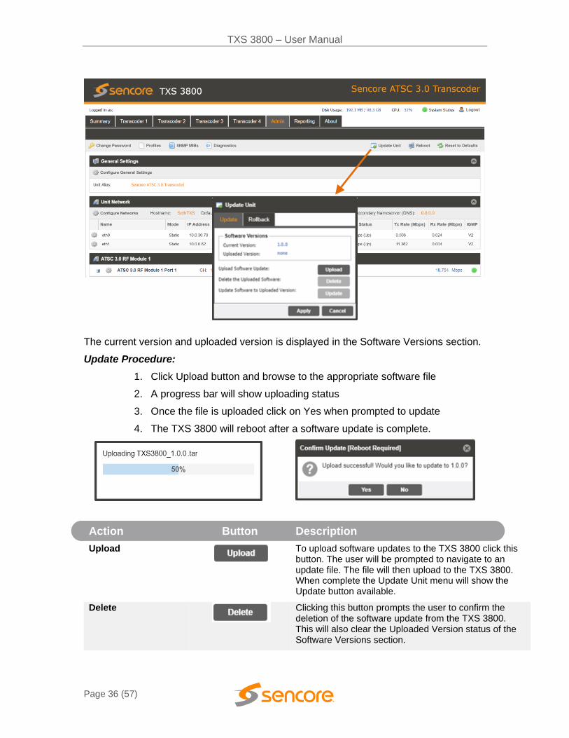
Once the software file is downloaded the update can be performed under the Admin tab of the TXS 3800 Web-Interface. Click on the Update Unit button in the top right of the page.
TXS 3800 – User Manual
Page 36 (57)
The current version and uploaded version is displayed in the Software Versions section.
Update Procedure:
1. Click Upload button and browse to the appropriate software file
2. A progress bar will show uploading status
3. Once the file is uploaded click on Yes when prompted to update
4. The TXS 3800 will reboot after a software update is complete.
Action Button Description
Upload
To upload software updates to the TXS 3800 click this button. The user will be prompted to navigate to an update file. The file will then upload to the TXS 3800. When complete the Update Unit menu will show the Update button available.
Delete
Clicking this button prompts the user to confirm the deletion of the software update from the TXS 3800. This will also clear the Uploaded Version status of the Software Versions section.
TXS 3800 – User Manual
Page 37 (57)
Update Software to Uploaded Version
Clicking the button starts the software update process. The TXS 3800 will prompt the user to confirm the update. Click Yes to continue or No to cancel.
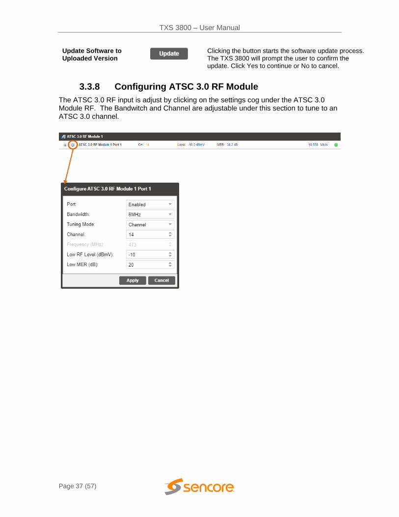
3.3.8 Configuring ATSC 3.0 RF Module
The ATSC 3.0 RF input is adjust by clicking on the settings cog under the ATSC 3.0 Module RF. The Bandwitch and Channel are adjustable under this section to tune to an ATSC 3.0 channel.

TXS 3800 – User Manual
Page 38 (57)
Setting Range Description
Port Enabled
Disabled
This setting allows the user to enable or disable this reception port.
Bandwidth 6, 7, 8 Mhz A user can manually select channel bandwidth
Channel 2-69 This setting is for the desired channel to be received.
Low RF Level (dBmV)
-90 to +20 Allows the trigger value for the Low RF Level alarm to be adjusted
Low MER (dB) 10 to 42 Allows the trigger value for the Low MER alarm to be adjusted
3.3.9 Rollback Software Updates
The TXS 3800 is capable of reverting back to a previous version of software using the Rollback feature. The TXS 3800 accomplishes this by maintaining two separate software images; one is the most current version of software with all current settings and the other is the previous version of software with all of the previous settings.
To perform a rollback, click the Update Unit button and then click the Rollback tab. The TXS 3800 will reboot after the rollback process is complete.
Action Button Description
Rollback
Clicking this button starts the Rollback process. The TXS 3800 will prompt the user to confirm the rollback or click cancel to stop the process.
3.3.10 Reboot Unit
The TXS 3800 can be rebooted from the web interface Admin page. In order to perform a reboot, click the reboot button. The TXS 3800 will prompt the user to confirm the reboot. Once the reboot is complete the login screen will appear allowing the web interface to be logged into.
TXS 3800 – User Manual
Page 39 (57)
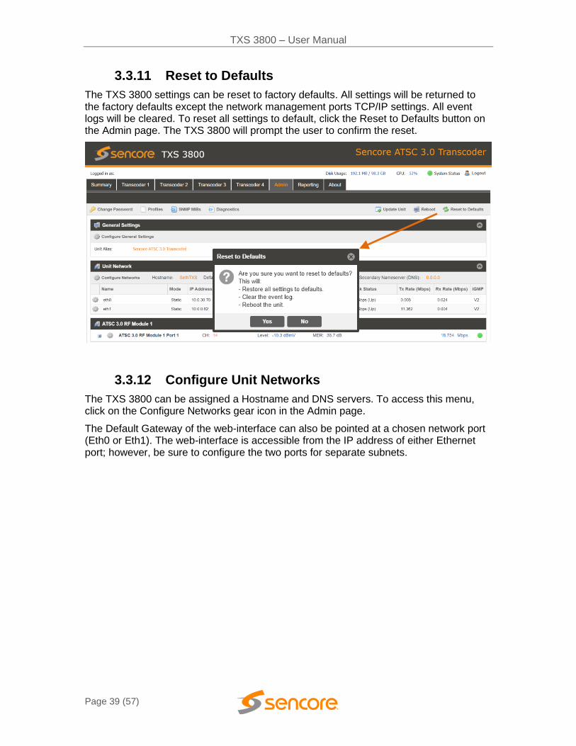
3.3.11 Reset to Defaults
The TXS 3800 settings can be reset to factory defaults. All settings will be returned to the factory defaults except the network management ports TCP/IP settings. All event logs will be cleared. To reset all settings to default, click the Reset to Defaults button on the Admin page. The TXS 3800 will prompt the user to confirm the reset.
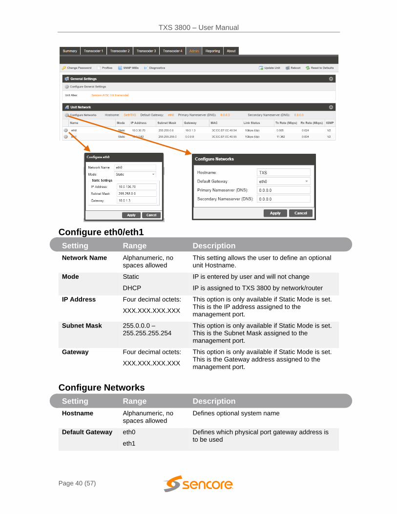
3.3.12 Configure Unit Networks
The TXS 3800 can be assigned a Hostname and DNS servers. To access this menu, click on the Configure Networks gear icon in the Admin page.
The Default Gateway of the web-interface can also be pointed at a chosen network port (Eth0 or Eth1). The web-interface is accessible from the IP address of either Ethernet port; however, be sure to configure the two ports for separate subnets.
TXS 3800 – User Manual
Page 40 (57)
Configure eth0/eth1
Setting Range Description
Network Name Alphanumeric, no spaces allowed
This setting allows the user to define an optional unit Hostname.
Mode Static
DHCP
IP is entered by user and will not change
IP is assigned to TXS 3800 by network/router
IP Address Four decimal octets:
XXX.XXX.XXX.XXX
This option is only available if Static Mode is set. This is the IP address assigned to the management port.
Subnet Mask 255.0.0.0 – 255.255.255.254
This option is only available if Static Mode is set. This is the Subnet Mask assigned to the management port.
Gateway Four decimal octets:
XXX.XXX.XXX.XXX
This option is only available if Static Mode is set. This is the Gateway address assigned to the management port.
Configure Networks
Setting Range Description
Hostname Alphanumeric, no spaces allowed
Defines optional system name
Default Gateway eth0
eth1
Defines which physical port gateway address is to be used

TXS 3800 – User Manual
Page 41 (57)
Primary Nameserver
Four decimal octets:
XXX.XXX.XXX.XXX
IP address of Primary (DNS) nameserver
Secondary Nameserver
Four decimal octets:
XXX.XXX.XXX.XXX
IP address of Secondary (DNS) nameserver
3.3.13 Software Support Agreements
Purchase of the TXS 3800 software includes one year of software support. This provides access to the latest software versions throughout that one-year period. These software versions include:
• Bug fixes
• General updates
• Maintenance releases
The TXS 3800 will only accept software updates which were released during the active SSA period. Software updates released following the expiration of the SSA will be rejected on upload, until the product’s SSA has been re-activated. The actual SSA information is maintained on the product itself and can be updated by applying a license key via the web user interface. The product’s user interface displays the end date to ensure the user is always informed of their SSA status. Regardless of the status of the software subscription agreement, Sencore offers phone and email technical support during regular business hours for all products.
Once the SSA period has expired, customers are free to keep using the software version they already have or other versions from before the expiration date but applying newer versions will require an extended SSA.
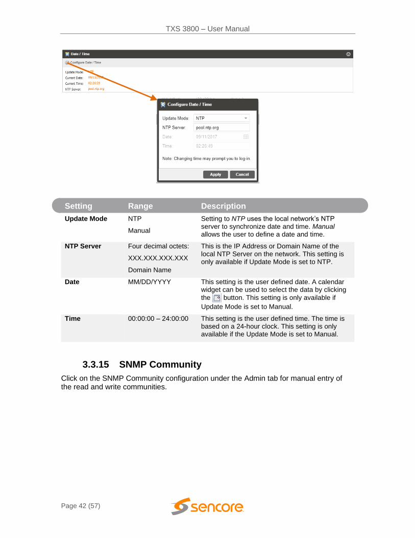
3.3.14 Date/Time
The TXS 3800 can be set to synchronize with an NTP server or a manual data and time can be defined by the user. Click the Configure Date / Time button to configure the date and time. These values are used to timestamp entries in the Alarm and Event logs under the Reporting tab.
TXS 3800 – User Manual
Page 42 (57)
Setting Range Description
Update Mode NTP
Manual
Setting to NTP uses the local network’s NTP server to synchronize date and time. Manual allows the user to define a date and time.
NTP Server Four decimal octets:
XXX.XXX.XXX.XXX
Domain Name
This is the IP Address or Domain Name of the local NTP Server on the network. This setting is only available if Update Mode is set to NTP.
Date MM/DD/YYYY
This setting is the user defined date. A calendar widget can be used to select the data by clicking
the button. This setting is only available if
Update Mode is set to Manual.
Time 00:00:00 – 24:00:00 This setting is the user defined time. The time is based on a 24-hour clock. This setting is only available if the Update Mode is set to Manual.
3.3.15 SNMP Community
Click on the SNMP Community configuration under the Admin tab for manual entry of the read and write communities.

TXS 3800 – User Manual
Page 43 (57)
3.3.16 SNMP Trap Manager
Click on the SNMP Trap Manager configuration icon to adjust the IP address of the SNMP trap destination. An example is provided below.
3.3.17 Syslog
The TXS 3800 can be configured to send error and event logs formatted in the syslog protocol to a remote user specified Syslog server.

TXS 3800 – User Manual
Page 44 (57)
Action Range Description
State Enabled
Disabled
Enable or Disable sending messages to Syslog server.
Network Protocol UDP
TCP
Select which network protocol used to transmit to the Syslog server
IP Address Four decimal octets:
XXX.XXX.XXX.XXX
IP of the Syslog server. 0.0.0.0 and 255.255.255.255 are not permitted
Port 0 - 65535 Destination port of the Syslog server
3.4 Reporting Panel
The Reporting tab in the TXS 3800 contains logs for active alarms currently affecting the unit and an event log. The active alarms are updated periodically in order to reflect the real-time state of the unit. Once an error is cleared it will be cleared from the active alarms window. The event log can be used to view alarm and event history. Both the active alarm and event logs can be configured to hide or change the behavior of alarms and events.
3.4.1 Active Alarms
Clicking on the Alarms button displays the Active Alarms menu. This list displays all of the active alarms currently affecting the unit. There are four columns in the log that display different types of information.

TXS 3800 – User Manual
Page 45 (57)
Title Description
State This column displays the nature of the alarm. The icon means the
log entry is informational and is not an error. The icon means the
log entry is an active alarm.
Name This column displays the description of the error. The function that is experiencing an error condition is described here.
Location This column displays the hardware or function that is experiencing the active error.
Last Changed This column displays the data and time the error was raised. This data and time correlates with the Date and Time settings configured in
Section 3.3.14.
3.4.2 Event Logs
Clicking on the Logs button displays all of the events and alarms that have affected the unit. If the unit is rebooted or powered off and on the event logs are cleared. The logs can be cleared manually by clicking the Clear button. The logs can be downloaded as a “.csv” file and saved to an external location by clicking the Download button.
Title Description
Severity This column displays the nature of the alarm. The icon means the
log entry is informational and is not an error. The icon means the
log entry is an active alarm.
Timestamp This column displays the data and time the error was raised or cleared. This data and time correlates with the Date and Time settings configured in Section 3.3.14.
Transition This column displays when an alarm transition from a bad to good
state. When an error is raised the icon is displayed. When an error
is cleared the icon is displayed. When an event takes place the
icon is displayed.
Message This column displays the description of the error or event. The function or hardware that experienced the event or error is described here.
Location This column displays the hardware or function that experienced the alarm or event.
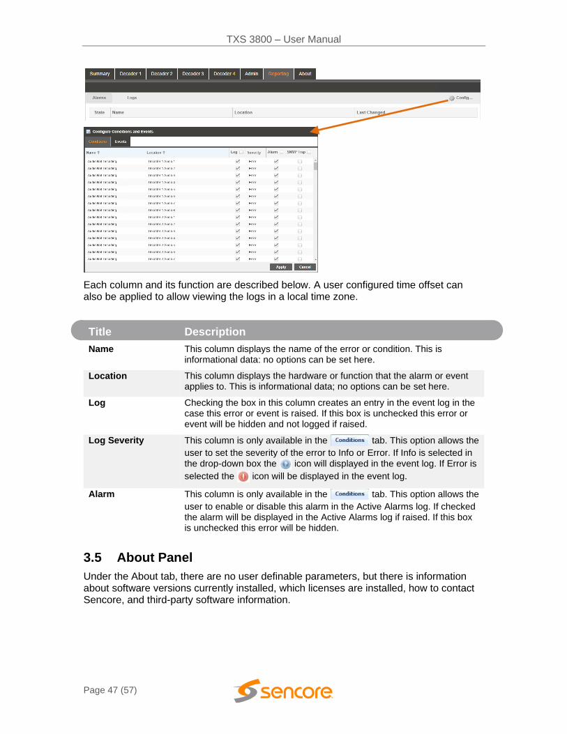
3.4.3 Configuring the Logs
The TXS 3800 allows the user to configure alarms and events. Events and alarms can be Logged, Hidden, or have the Severity adjusted.

TXS 3800 – User Manual
Page 46 (57)
In order to configure these options, click the Configure button while in the section of the Reporting tab.
Logs and events can be configured separately for every transcoder panel.
TXS 3800 – User Manual
Page 47 (57)
Each column and its function are described below. A user configured time offset can also be applied to allow viewing the logs in a local time zone.
Title Description
Name This column displays the name of the error or condition. This is informational data: no options can be set here.
Location This column displays the hardware or function that the alarm or event applies to. This is informational data; no options can be set here.
Log Checking the box in this column creates an entry in the event log in the case this error or event is raised. If this box is unchecked this error or event will be hidden and not logged if raised.
Log Severity This column is only available in the tab. This option allows the
user to set the severity of the error to Info or Error. If Info is selected in the drop-down box the icon will displayed in the event log. If Error is
selected the icon will be displayed in the event log.
Alarm This column is only available in the tab. This option allows the
user to enable or disable this alarm in the Active Alarms log. If checked the alarm will be displayed in the Active Alarms log if raised. If this box is unchecked this error will be hidden.
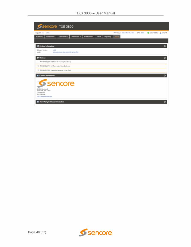
3.5 About Panel
Under the About tab, there are no user definable parameters, but there is information about software versions currently installed, which licenses are installed, how to contact Sencore, and third-party software information.
TXS 3800 – User Manual
Page 48 (57)
TXS 3800 – User Manual
Page 49 (57)
Section 4 Appendices
Introduction
This section includes the following appendices:
APPENDIX A – ACRONYMS AND GLOSSARY 50
APPENDIX B – ERROR AND EVENT LIST 51
APPENDIX C – SPECIFICATIONS 52
APPENDIX D – OPEN SOURCE SOFTWARE 54
APPENDIX E – WARRANTY 56
APPENDIX F – SUPPORT AND CONTACT INFORMATION 56
TXS 3800 – User Manual
Page 50 (57)
Appendix A – Acronyms and Glossary
AAC: Advanced Audio Coding AC-4: Dolby Audio Compression AES: Audio Engineering Society ATSC: Advanced Television Systems Committee Bit Rate: The rate at which the compressed bit stream is delivered from the channel to
the input of a decoder. BNC: British Naval Connector dB: Decibel DHCP: Dynamic Host Configuration Protocol DVB: Digital Video Broadcasting Event: An event is defined as a collection of elementary streams with a common time
base, an associated start time, and an associated end time. FCC: Federal Communications Commission FHD: Full High Definition HD: High Definition HEVC/H.265: High Efficiency Video Coding I/O: Input/Output IP: Internet Protocol Kbps: 1000 bit per second LED: Light Emitting Diode LLS: Low Level Signaling Mbps: 1,000,000 bits per second. NTP: Networking Time Protocol PCM: Pulse-Code Modulation PID: Packet Identifier. A unique integer value used to associate elementary streams of a
program in a single or multi-program transport stream. PLP: Physical Layer Pipes
Program specific information (PSI): PSI consists of normative data which is necessary for the demultiplexing of transport streams and the successful regeneration of programs.
Program: A program is a collection of program elements. Program elements may be elementary streams. Program elements need not have any defined time base; those that do have a common time base and are intended for synchronized presentation.
RU: Rack Unit SD: Standard Definition SDI: Serial Digital Interface SI: System Information SMPTE: Society of Motion Pictures and Television Engineers SNMP: Simple Network Management Protocol TS: Transport Stream UHD: Ultra High Definition
TXS 3800 – User Manual
Page 51 (57)
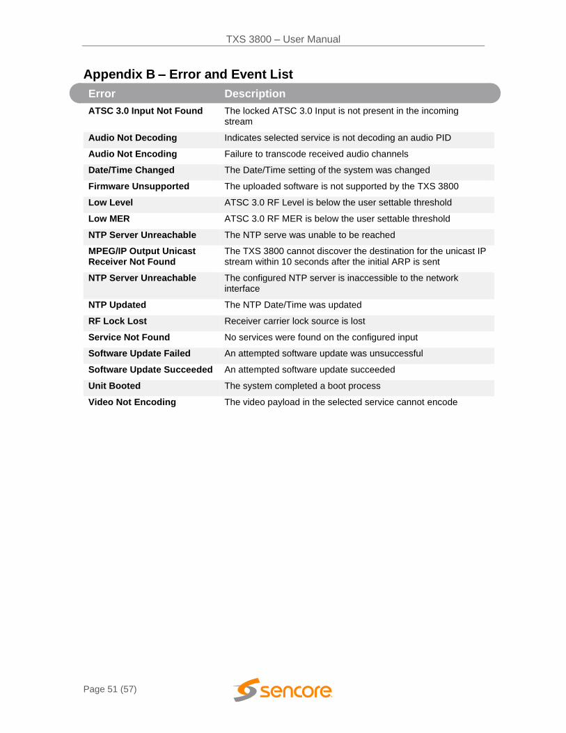
Appendix B – Error and Event List
Error Description
ATSC 3.0 Input Not Found The locked ATSC 3.0 Input is not present in the incoming stream
Audio Not Decoding Indicates selected service is not decoding an audio PID
Audio Not Encoding Failure to transcode received audio channels
Date/Time Changed The Date/Time setting of the system was changed
Firmware Unsupported The uploaded software is not supported by the TXS 3800
Low Level ATSC 3.0 RF Level is below the user settable threshold
Low MER ATSC 3.0 RF MER is below the user settable threshold
NTP Server Unreachable The NTP serve was unable to be reached
MPEG/IP Output Unicast Receiver Not Found
The TXS 3800 cannot discover the destination for the unicast IP stream within 10 seconds after the initial ARP is sent
NTP Server Unreachable The configured NTP server is inaccessible to the network interface
NTP Updated The NTP Date/Time was updated
RF Lock Lost Receiver carrier lock source is lost
Service Not Found No services were found on the configured input
Software Update Failed An attempted software update was unsuccessful
Software Update Succeeded An attempted software update succeeded
Unit Booted The system completed a boot process
Video Not Encoding The video payload in the selected service cannot encode
TXS 3800 – User Manual
Page 52 (57)
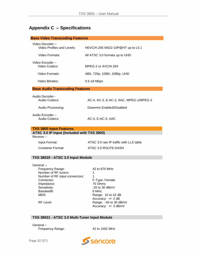
Appendix C – Specifications
Base Video Transcoding Features
Video Decoder – Video Profiles and Levels: HEVC/H.265 M422-10P@HT up to L5.1
Video Formats: All ATSC 3.0 formats up to UHD
Video Encoder –
Video Codecs Video Formats: Video Bitrates:
MPEG-2 or AVC/H.264 480i, 720p, 1080i, 1080p, UHD 0.5-18 Mbps
Base Audio Transcoding Features HEVC/H.265 M422-10P@HT up to L5.1
Audio Decoder -
Audio Codecs: AC-4, AC-3, E-AC-3, AAC, MPEG-1/MPEG-2
Audio Processing:
Downmix Enabled/Disabled
Audio Encoder – Audio Codecs:
AC-3, E-AC-3, AAC
TXS 3800 Input Features ATSC 3.0 IP Input (Included with TXS 3800) Receive –
Input Format:
Container Format:
ATSC 3.0 raw IP traffic with LLS table
ATSC 3.0 ROUTE-DASH
TXS 38020 - ATSC 3.0 Input Module General –
Frequency Range: 42 to 870 MHz Number of RF tuners: Number of RF input connectors:
1 1
Connector: F-Type, Female Impedance: 75 Ohms Sensitivity: -20 to 30 dBmV Bandwidth 6 MHz MER: Range: 10 to 42 dB
Accuracy: +/- 2 dB RF Level: Range: -40 to 30 dBmV
Accuracy: +/- 3 dBmV
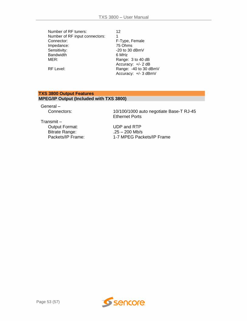
TXS 38021 - ATSC 3.0 Multi-Tuner Input Module General –
Frequency Range: 42 to 1002 MHz
TXS 3800 – User Manual
Page 53 (57)
Number of RF tuners: Number of RF input connectors:
12 1
Connector: F-Type, Female Impedance: 75 Ohms Sensitivity: -20 to 30 dBmV Bandwidth 6 MHz MER: Range: 3 to 40 dB
Accuracy: +/- 2 dB RF Level: Range: -40 to 30 dBmV
Accuracy: +/- 3 dBmV
TXS 3800 Output Features MPEG/IP Output (Included with TXS 3800)
General – Connectors: 10/100/1000 auto negotiate Base-T RJ-45
Ethernet Ports Transmit –
Output Format: UDP and RTP Bitrate Range: .25 – 200 Mb/s Packets/IP Frame: 1-7 MPEG Packets/IP Frame

TXS 3800 – User Manual
Page 54 (57)
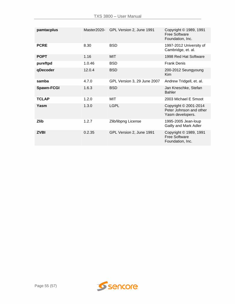
Appendix D – Open Source Software
The TXS 3800 includes:
Package Version License Copyright
BusyBox 1.24.2 GPL Version 2, June 1991 Erik Anderson, et. al.
Dropbear 2016.74 MIT-like 2002-20015 Matt Johnston, et. al (see license)
e2fsprogs 1.43.4 GPL Version 2, June 1991 Theodore Ts’o
ethtool 4.13 GPL Version 2, June 1991 David Miller, et. al.
FamFamFam Silk Icons 013 Creative Commons Attribution 2.5
Mark James
FastDB 3.71 MIT-like Konstantin Knizhnik
FCGI 2.4.6 FastCGI Open Market, Inc
FFmpeg 3.4 LGPL Version 2.1 Feb 1999 Fabrice Bellard
gptfdisk 1.0.3 GPL Version 2, June 1991 Roderick W. Smith
grub 2.00 GPL Version 3, 29 June 2007 Copyright © 1994 – 2011 Free Software Foundation, Inc.
heimdal 7.1.0 BSD Copyright © 1995 – 2014 Kungliga Tekniska Hogskolan
libfdk-aac 0.1.6 Fraunhofer-Gasellshaft © Copyright 1995 – 2018 Fraunhofer-Gesellshaft zur Foderrung der angewandten Forschung e.V.
libpcap 1.8.1 BSD 1994, 1995, 1996 The Regents of the University of California
libx264 20171022-22
GPL Version 2, June 1991 Copyright © 1989, 1991 Free Software Foundation, Inc.
Lighttpd 1.4.30 BSD 2004, Jan Kneschke
Linux 4.4.20 GPL Version 2, June 1991 Linus Torvalds, et. Al.
Log4cpp 1.0 GPL Version 2.1 Feb 1999 Bastiann Bakker
Net-SNMP 5.7.1 BSD 1989, 1991, 1992 by Carnegie Mellon Univsty.
NTP 4.2.4p7 NTP License 1992-2009 David L. Mills
OpenSSL 1.0.1c BSD-Like 1998-2008 The OpenSSL Project, 1995-1998
pammodules 1.3.1 BSD-Like Copyright © Andrew G. Morgan 1996-9
TXS 3800 – User Manual
Page 55 (57)
pamtacplus Master2020- GPL Version 2, June 1991 Copyright © 1989, 1991 Free Software Foundation, Inc.
PCRE 8.30 BSD 1997-2012 University of Cambridge, et. al.
POPT 1.16 MIT 1998 Red Hat Software
pureftpd 1.0.46 BSD Frank Denis
qDecoder 12.0.4 BSD 200-2012 Seungyoung Kim
samba 4.7.0 GPL Version 3, 29 June 2007 Andrew Tridgell, et. al.
Spawn-FCGI 1.6.3 BSD Jan Kneschke, Stefan Bahler
TCLAP 1.2.0 MIT 2003 Michael E Smoot
Yasm 1.3.0 LGPL Copyright © 2001-2014 Peter Johnson and other Yasm developers.
Zlib 1.2.7 Zlib/libpng License 1995-2005 Jean-loup Gailly and Mark Adler
ZVBI 0.2.35 GPL Version 2, June 1991 Copyright © 1989, 1991 Free Software Foundation, Inc.

TXS 3800 – User Manual
Page 56 (57)
Appendix E – Warranty
Sencore Hardware One-Year Warranty
Sencore warrants this instrument against defects from any cause, except acts of God and abusive use, for a period of 1 (one) year from date of purchase. During this warranty period, Sencore will correct any covered defects without charge for parts, labor, or recalibration.
Appendix F – Support and Contact Information
Returning Products for Service or Calibration
The TXS 3800 server is a delicate piece of equipment and needs to be serviced and repaired by Sencore. Periodically it is necessary to return a product for repair or calibration. In order to expedite this process please carefully read the instructions below.
RMA Number
Before any product can be returned for service or calibration, an RMA number must be obtained. In order to obtain a RMA number, use the following steps:
1. Contact the Sencore service department by going online to www.sencore.com and select Support.
2. Select Service and Repair from the options given.
3. Fill in the following required information:
a. First & Last Name
b. Company
c. Email
d. Phone Number
e. Ship and Bill to Address
f. Unit Model and Serial Numbers
4. A RMA number will be emailed you shortly after completing the form with return instructions.
Shipping the Product
Once an RMA number has been issued, the unit needs to be packaged and shipped back to Sencore. It’s best to use the original box and packaging for the product but if this not available, check with the customer service representative for the proper packaging instructions.
Note: DO NOT return any power cables or accessories unless instructed to do so by the customer service representative

Sencore Inc.
3200 Sencore Drive
Sioux Falls, SD 57107 USA
www.sencore.com
Copyright © 2021 Sencore Inc. 1.605.978.4600