TX9100E User Manual (Page 1) - LUX Products Pro Solutions
32
1. SYSTEM COMPATIBILITY . . . . . . . . 2 2. FEATURES . . . . . . . . . . . . . . . . . . 3 3. TOOLS REQUIRED . . . . . . . . . . . . . 3 4. SELECTING A LOCATION . . . . . . . . . 4 5. REMOVE OLD THERMOSTAT . . . . . . 5 6. MOUNT NEW THERMOSTAT . . . . . . 5 7. WIRING DIAGRAMS . . . . . . . . . . . . 6 8. HARDWARE SETUP OPTIONS . . . . 16 9. COMPLETE THE INSTALL . . . . . . . 18 10. FRONT PANEL ITEMS . . . . . . . . . . 19 11. OPERATING INSTRUCTIONS . . . . . 20 12. ADVANCED FEATURES . . . . . . . . . 24 13. PROGRAMMING . . . . . . . . . . . . . 29 14. BATTERIES AND MAINTENANCE. . . 30 15. TECHNICAL ASSISTANCE . . . . . . . 31 16. WARRANTY. . . . . . . . . . . . . . . . . 31 WARNING: Use Energizer ® or DURACELL ® Alkaline Batteries Only. Energizer ® is a registered trademark of Eveready Battery Company, Inc. DURACELL ® is a registered trademark of The Gillette Company, Inc. © 2008 LUX PRODUCTS CORPORATION. ALL RIGHTS RESERVED PSP721U SMART TEMP ® UNIVERSAL PROGRAMMABLE THERMOSTAT FOR BOTH CONVENTIONAL AND HEAT PUMP SYSTEMS INSTALLATION AND OPERATING INSTRUCTIONS IMPORTANT! • Please read all instructions carefully before beginning installation • Label the terminal designations on your existing wiring before removing your existing thermostat • Ignore the color of the wires since they may not comply with any standard. Thank you for your confidence in our product. To obtain the best results from your investment, please read these instructions and acquaint yourself with your purchase. Follow the installation procedures carefully, and one step at a time. This will save you time and minimize the chance of damaging either the thermostat or the systems that it controls. These instructions may contain information beyond that required for your particular installation. 52033
Transcript of TX9100E User Manual (Page 1) - LUX Products Pro Solutions

1. SYSTEM COMPATIBILITY . . . . . . . . 2
2. FEATURES . . . . . . . . . . . . . . . . . . 3
3. TOOLS REQUIRED . . . . . . . . . . . . . 3
4. SELECTING A LOCATION. . . . . . . . . 4
5. REMOVE OLD THERMOSTAT . . . . . . 5
6. MOUNT NEW THERMOSTAT . . . . . . 5
7. WIRING DIAGRAMS . . . . . . . . . . . . 6
8. HARDWARE SETUP OPTIONS . . . . 16
9. COMPLETE THE INSTALL . . . . . . . 18
10. FRONT PANEL ITEMS . . . . . . . . . . 19
11. OPERATING INSTRUCTIONS . . . . . 20
12. ADVANCED FEATURES . . . . . . . . . 24
13. PROGRAMMING . . . . . . . . . . . . . 29
14. BATTERIES AND MAINTENANCE. . . 30
15. TECHNICAL ASSISTANCE . . . . . . . 31
16. WARRANTY. . . . . . . . . . . . . . . . . 31
WARNING: Use Energizer® or DURACELL® Alkaline Batteries Only.Energizer® is a registered trademark of Eveready Battery Company, Inc.
DURACELL® is a registered trademark of The Gillette Company, Inc.
© 2008 LUX PRODUCTS CORPORATION. ALL RIGHTS RESERVED
PSP721USMART TEMP® UNIVERSAL PROGRAMMABLE THERMOSTAT
FOR BOTH CONVENTIONAL AND HEAT PUMP SYSTEMS
INSTALLATION AND OPERATING INSTRUCTIONS
IMPORTANT!• Please read all instructions carefully before beginning installation• Label the terminal designations on your existing wiring before
removing your existing thermostat• Ignore the color of the wires since they may not comply with any
standard.
Thank you for your confidence in our product. To obtain thebest results from your investment, please read theseinstructions and acquaint yourself with your purchase. Followthe installation procedures carefully, and one step at a time.This will save you time and minimize the chance of damagingeither the thermostat or the systems that it controls. Theseinstructions may contain information beyond that required foryour particular installation.
52033

2
1. SYSTEM COMPATIBILITY
The electrical rating for this thermostat is 1.5A per terminal,with a maximum of 2.0A for all terminals combined.
COMPATIBLE WITH:• Most 24-volt heating and cooling systems• 1 or 2 stage Heat / 1 stage Cool: Gas, Oil or Electric systems• 1 or 2 stage Heat / 1 stage Cool: Heat Pump systems• 3-wire hydronic (hot water) zone valves• Gas Millivolt heaters
NOT COMPATIBLE WITH:• 120/240 VAC line voltage systems without a transformer, askyour LUXPRO dealer for thermostats to control these systems.
NEXT
HOLD
COPY / EMER
COOLPROGRAM
HEATPROGRAM
SETDAY/TIME
R U N
AIR FILTER
RESET
FAN TEMERATURE
AUTO
ON
HEATOFFCOOL
LUXLUX
5:36 72HEAT
TUDAY
F
PM
PSP721U Up / Down Buttons
LCDDisplayScreen
SystemMode
Switch
FanMode
Switch
Quick ReferenceInstructions
LUX Rotary Speed Dial®

3
2. THERMOSTAT FEATURES
• Universal Compatibility (Conventional or Heat Pump)• 7 Day Programming• 4 Periods per Day• Quick Copy Programming• Exclusive LUX Speed Dial®
• Luxlight® EL (Electro-Luminescent) Illuminated Display• Filter Monitor• Programmable Keypad Lock• Optional Smart Recovery• Temperature Hold• Temporary Temperature Override• Energy Star Compliant• Battery Free Memory Storage• F/C Temperature Display• 12/24 Hr Clock Display• Adjustable Temperature Differential / Cycle Rate• User Temperature Calibration• System or Battery Powered• 5/2 Minute Selectable Minimum Run/Off Time for
Equipment Protection
Please read all of these instructions carefully beforebeginning installation, and save this manual for futurereference.
3. TOOLS REQUIRED
• #1 Phillips screwdriver• Drill with 3/16 in. (4.8mm) bit• Wire Stripper / Cutter

4
CAUTION:This thermostat is protected against normal static electricdischarges; however touching a grounded metal objectbefore touching your thermostat will minimize the risk ofdamaging the unit in extremely dry weather.
4. SELECTING A LOCATION
On replacement installations, mount the new thermostat inplace of the old one unless the conditions listed belowsuggest otherwise. On new installations, follow theguidelines listed below.
1. Locate the thermostat on an inside wall, about 5 ft. (1.5m)above the floor, and in a room that is used often.
2. Do not locate where air circulation is poor, such as in acorner or an alcove, or behind an open door.
3. Do not install it where there are unusual heatingconditions, such as: in direct sunlight; near a lamp,television, radiator, register, or fireplace; near hot waterpipes in a wall; near a stove on the other side of a wall.
4. Do not locate in unusual cooling conditions, such as: on awall separating an unheated room; or in a draft from astairwell, door, or window.
5. Do not locate in a damp area. This can lead to corrosionthat may shorten thermostat life.
6. If painting or construction work has yet to be completed,cover the unit completely or do not install it.
WARNING:• Read instructions carefully before removing any wires from
your existing thermostat.• All wiring must conform to the local codes and ordinances
that are in your particular location.
5
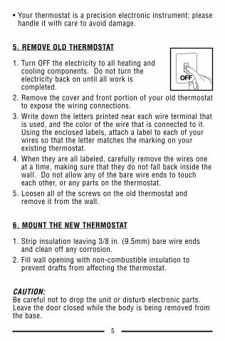
• Your thermostat is a precision electronic instrument; pleasehandle it with care to avoid damage.
5. REMOVE OLD THERMOSTAT
1. Turn OFF the electricity to all heating andcooling components. Do not turn theelectricity back on until all work iscompleted.
2. Remove the cover and front portion of your old thermostatto expose the wiring connections.
3. Write down the letters printed near each wire terminal thatis used, and the color of the wire that is connected to it.Using the enclosed labels, attach a label to each of yourwires so that the letter matches the marking on yourexisting thermostat.
4. When they are all labeled, carefully remove the wires oneat a time, making sure that they do not fall back inside thewall. Do not allow any of the bare wire ends to toucheach other, or any parts on the thermostat.
5. Loosen all of the screws on the old thermostat andremove it from the wall.
6. MOUNT THE NEW THERMOSTAT
1. Strip insulation leaving 3/8 in. (9.5mm) bare wire endsand clean off any corrosion.
2. Fill wall opening with non-combustible insulation toprevent drafts from affecting the thermostat.
CAUTION:Be careful not to drop the unit or disturb electronic parts.Leave the door closed while the body is being removed fromthe base.
OFF
6
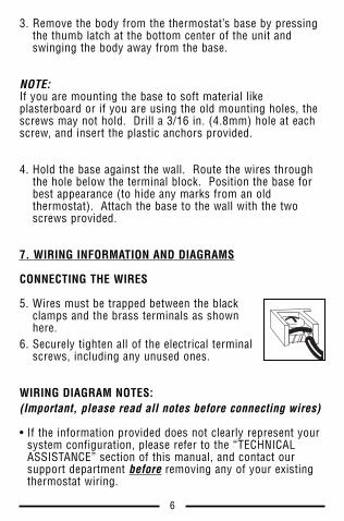
3. Remove the body from the thermostat’s base by pressingthe thumb latch at the bottom center of the unit andswinging the body away from the base.
NOTE:If you are mounting the base to soft material likeplasterboard or if you are using the old mounting holes, thescrews may not hold. Drill a 3/16 in. (4.8mm) hole at eachscrew, and insert the plastic anchors provided.
4. Hold the base against the wall. Route the wires throughthe hole below the terminal block. Position the base forbest appearance (to hide any marks from an oldthermostat). Attach the base to the wall with the twoscrews provided.
7. WIRING INFORMATION AND DIAGRAMS
CONNECTING THE WIRES
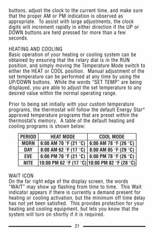
5. Wires must be trapped between the blackclamps and the brass terminals as shownhere.
6. Securely tighten all of the electrical terminalscrews, including any unused ones.
WIRING DIAGRAM NOTES:(Important, please read all notes before connecting wires)
• If the information provided does not clearly represent yoursystem configuration, please refer to the “TECHNICALASSISTANCE” section of this manual, and contact oursupport department before removing any of your existingthermostat wiring.

7
• All of the dashed wires shown in the following wiringdiagrams are either optional, or their usage depends uponyour specific system type or brand. For example: Diagram#1 shows the fan wire as optional. If your system does nothave a fan, than this terminal will not be used.
• The optional “C” terminal is used for powering thethermostat by the 24 Volt system power. This can be usedalone, or in addition to installing batteries.
• If “Y” and “C” wires are both present, then “C” is mostlikely a system common wire.
• For Heat Pump systems, use either the “O” terminal or the“B” terminal, but not both. If an “O” and a “B” wire areboth present, “B” is likely a system common and may beconnected to the “C” terminal. Connecting systemcommon power to this thermostat’s “B” terminal maydamage the thermostat, and also your system.
• If replacing a Honeywell TM-11, tape off the “R” wire.Connect the “B” wire to the “RH” terminal.
• If replacing an old thermostat that has a mechanical clock,there may be two wires labeled as “C” for the clock power.Tape off these wires and do not connect them to the “C”terminal of this thermostat.

8
RCG
RHY
W2W1
AO
BC
FAN
HEA
TER
SYST
EMX
FMR
TYP
ICA
L 24
-VO
LT,
2 O
R 3
WIR
E, C
ON
VEN
TIO
NA
L,1-
STA
GE,
HEA
TIN
G O
NLY
SY
STE
MS
(IN
CLU
DIN
G M
ILLI
VO
LT)
G F
RH R V
CW
1 W H 4
Fact
ory
RH
-RC
Jum
per
Wir
e In
stal
led
O P T I O N A L
#1

9
RCG
RHY
W2W1
AO
BC
3-W
IRE
HY
DR
ON
ICZ
ON
E V
ALV
E
SYST
EMX
FMR
TYP
ICA
L 24
-VO
LT,
CO
NV
ENTI
ON
AL,
1-S
TAG
E, H
OT
WAT
ERH
EAT
ON
LY S
YS
TEM
S W
ITH
A 3
-WIR
E ZO
NE
VALV
E
A 6
RH R V
3Y
W1 W H 4
C
Fact
ory
RH
-RC
Jum
per
Wir
e In
stal
led
O P T I O N A L
#2

10
RCG
RHY
W2W1
AO
BC
FAN
A/C
UN
ITSY
STEM
XFM
R
TYP
ICA
L 24
-VO
LT,
3 W
IRE,
CO
NV
ENTI
ON
AL,
1-S
TAG
E C
OO
LIN
G O
NLY
SY
STE
MS
RC R 5
G F
Y C* 6
C
Fact
ory
RH
-RC
Jum
per
Wir
e In
stal
led
O P T I O N A L
#3

11
RCG
RHY
W2W1
AO
BC
FAN
HEA
TER
SYST
EMX
FMR
TYP
ICA
L 24
V, 4
WIR
E, C
ON
VEN
TIO
NA
L H
EATI
NG
AN
D C
OO
LIN
GS
YS
TEM
S W
ITH
1 S
TAG
E H
EAT
AN
D 1
STA
GE
CO
OL
A/C
UN
IT
RH R V
G F
Y C* 6
W1 W H 4
C
Fact
ory
RH
-RC
Jum
per
Wir
e In
stal
led
O P T I O N A L
#4

12
RCG
RHY
W2W1
AO
BC
FAN
SYST
EMX
FMR
TYP
ICA
L 24
V, 5
WIR
E, C
ON
VEN
TIO
NA
L H
EATI
NG
AN
D C
OO
LIN
GS
YS
TEM
S W
ITH
2 S
TAG
E H
EAT
AN
D 1
STA
GE
CO
OL
HEA
TSE
CO
ND
STA
GE
HEA
TFI
RST
STA
GE
A/C
UN
IT
W2
RH R V
G F
Y C* 6
W1 W H 4
C
Fact
ory
RH
-RC
Jum
per
Wir
e In
stal
led
O P T I O N A L
#5

13
RCG
RHY
W2W1
AO
BC
TYP
ICA
L 24
V, 4
WIR
E, H
EAT
PU
MP
SY
STE
MS
WIT
H 1
STA
GE
HEA
T A
ND
1 S
TAG
E C
OO
L
FAN
SYST
EMX
FMR
HEA
TP
UM
PU
NIT
CH
AN
GE-
OV
ERV
ALV
E
** U
se e
ithe
r “O
” or
“B
”Te
rmin
al,
Nev
er B
oth
RC R 5
G F
Y C* 6
OB
C
Fact
ory
Sup
plie
d R
H-R
CJu
mpe
r W
ire
Inst
alle
dC
usto
mer
Sup
plie
dJu
mpe
r W
ire
Inst
alle
d
O P T I O N A L
#6

14
RCG
RHY
W2W1
AO
BC
TYP
ICA
L 24
V, 5
WIR
E, H
EAT
PU
MP
SY
STE
MS
WIT
H 2
STA
GE
HEA
T A
ND
1 S
TAG
E C
OO
L
FAN
SYST
EMX
FMR
HEA
TP
UM
PU
NIT
CH
AN
GE-
OV
ERV
ALV
E
** U
se “
O”
or “
B”
Term
inal
s, N
ever
Bot
h
AU
XIL
IAR
YH
EAT
RC R 5
W2
G F
Y C* 6
CB
O
O P T I O N A L
#7
Fact
ory
Sup
plie
d R
H-R
CJu
mpe
r W
ire
Inst
alle
dC
usto
mer
Sup
plie
dJu
mpe
r W
ire
Inst
alle
d

15
RCG
RHY
W2W1
AO
BC
FAN
HEA
TER
HEA
TX
FMR
TYP
ICA
L 24
V, 5
WIR
E, C
ON
VEN
TIO
NA
L H
EATI
NG
AN
D C
OO
LIN
GS
YS
TEM
S W
ITH
1 S
TAG
E H
EAT
AN
D 1
STA
GE
CO
OL,
WIT
H T
WO
24-
VO
LT T
RA
NS
FOR
MER
S
A/C
UN
ITC
OO
LX
FMR
RC R 5
RH R V
G F
Y C* 6
W1 W H 4
C
**Fa
ctor
y R
H-R
C J
umpe
r W
ire
REM
OV
ED
O P T I O N A L
#8

16
8. HARDWARE SETUP OPTIONS
NOTE:All of the settings, options, and components listed in thefollowing section are located on the rear of the thermostat,on the circuit board.
GAS/ELEC. FAN OPERATIONThis is a plastic jumper cap, which islabeled as JP2. This jumper must remaininstalled, and can be in one of twopositions, GAS or ELECTRIC.
This setting changes how the system’s blower fan (ifapplicable) is controlled while in HEAT mode, and with theFan switch in the AUTO position. This setting does notaffect fan operation while in COOL mode. When set to“Gas”, the fan is controlled solely by the heating systemitself. When set to “Electric”, the fan is controlled directlyby the thermostat. NOTE: If your blower fan does notoperate properly after installation, move the Gas / Electricoption to the “Electric” setting.
OPTION SWITCHES:
The following option settings are all locatedwithin a group of small switches labeled 1through 6 as shown, and are located in thecenter of the circuit board. Changes made toany of these switches are recognized oninitial power up, or when the front panelTemperature Mode switch position has beenaltered in any direction if the thermostat isalready being powered by batteries.
ELECRIC
GAS
JP2
ON1
23
45
6

17
[1] SYSTEM MODEThis setting tells the thermostat about the type of heatingand cooling equipment that it is controlling, so that thesystem is operated properly. This switch needs to be in theOFF (NON-HP) position if you have a furnace or conventionalheating and air conditioning system. If you have a HeatPump system, the switch needs to be in the ON (HP)position; this is applicable even if your heat pump systemhas an auxiliary heat stage that is a gas furnace.
[2] RECOVERYThe Early Recovery feature affects how the thermostattransitions from an energy saving setback temperature, to acomfort temperature. Normally the change in temperatureonly starts to occur at an upcoming period's start time.
With Early Recovery Disabled: If you have programmed yourthermostat for 70°F at 5:00PM, the thermostat will onlybegin to heat your home back up when the time reaches5:00PM. With Early Recovery Enabled: Using the samescenario as above, the thermostat will calculate the best timeto turn on the heater, so that the temperature in your homereaches 70°F as close to 5:00PM as possible. During thetime that the thermostat is performing a recovery, the words“IN RECOVERY” will flash in the temperature portion of thedisplay screen. Switch position OFF is Recovery Disabled,and ON is Recovery Enabled.
[3] DELAYThis sets the minimum length of time that Heat or Cool mustremain either On or Off, before it will automatically switch tothe alternate On or Off state. This Delay prevents rapidcycling of your system and provides equipment protectionfor cooling units. Switch position OFF is a 5 minute delay,and ON is a 2 minute delay. 5 minutes is the default setting,and is good for most applications. If you feel that yoursystem is trying to cycle more rapidly than every 5 minutes,you may try the 2 minute setting.

18
[4] SCALEThis setting determines how the thermostat displays alltemperatures on the screen. Switch position OFF is F°, andON is C°.
[5] TIMEThis setting determines how the thermostat displays theclock and all other time values on the screen. Switchposition OFF is 12 HR (US Standard), and ON is 24 HR(Military Time).
[6] BATTERY MONITORThis determines whether the internal battery voltage monitorwatches the condition of the batteries that are installed in thethermostat. This setting should always remain enabledunless the thermostat is being powered by System Poweralone, without any batteries present. Switch position OFF isBattery Monitor On (Enabled), and Switch position ON isBattery Monitor Off (Disabled).
WARNING:Undesired operation may result if the battery monitor is setto “Disabled” while this thermostat has batteries installed.
9. COMPLETING THE INSTALLATION
Once all hardware option settings are performed, install twonew Energizer® or DURACELL® "AA" size alkaline batteriesbefore continuing further. Ensure that the batteries areinstalled in the proper direction as per the markings shownin the battery tray. If batteries were already installed beforesetting changes were performed, simply change theTemperature Mode switch on the front panel to any otherposition so that the new settings may be recognized by thethermostat.

19
NOTE:When you are finished performing your installation and setupoptions, please remove the thin plastic film that is protectingthe LCD display screen on the front of the thermostat. Thisplastic may or may not be present, and is evident by theappearance of fake digits appearing on the display screen.
10. FRONT PANEL ITEMS
RESETThe RESET button is a small recessed push button that islocated right above the NEXT button behind the front door.This button can be pushed with a pencil or the end of apaper clip. This reset returns the heating and coolingprograms to their default Energy Star values, resets the filtercounter, and all other user changeable software options totheir default values. It is recommended that you write downyour current heating and cooling program start times andtemperatures prior to pressing the software reset button.
MODE SWITCHESThere are two mode switches on the front, a TEMPERATUREMode switch and a FAN Mode switch.
The TEMPERATURE Mode switch has three positions: HEAT,OFF, and COOL. In the winter, set the switch to HEAT tocontrol your heating system. In the summer, set the switchto COOL to control your cooling system. In the spring andfall or when the windows are open, you can set the switch toOFF to prevent heating or cooling operation.
The FAN Mode switch has two positions, AUTO and ON.Setting the Fan switch to AUTO automatically runs yoursystem's blower fan as required, only during heating orcooling activation. Setting the Fan switch to ON, runs yoursystem’s fan continuously, even if heating or cooling is not

20
needed. With the Fan switch in the ON position, the fan willoperate even when the Temperature Mode switch is in theOFF position to provide air circulation only. When the fan isrunning, the word “FAN” is displayed in the temperatureportion of the display screen.
NOTE:The Fan Mode switch only works if your system provides awire for the thermostat’s “G” wire terminal, to control ablower fan. The Fan Mode switch has no effect in systemsthat do not have a blower fan (such as a hot water radiatorsystem).
PUSH BUTTONSThere are five primary push buttons on the front of thethermostat: The UP and DOWN arrow keys, the NEXT button,The HOLD button, and the COPY/EMER button.
ROTARY DIALThe LUX Speed Dial® provides an easy way to quicklynavigate between the different programming areas. Thisrotary dial has five individual positions and should alwaysremain in the RUN position, unless a specific action is beingperformed in one of the other positions.
11. OPERATING INSTRUCTIONS
SET DAY/TIMERotate the dial to the SET DAY/TIME position. You shouldsee the word SET appear in the upper left corner of thedisplay, along with the clock and a day of the week that isflashing. With the day flashing, press either the UP orDOWN buttons to make the current day flashing. Press theNEXT button; this should cause the time to start flashing andthe day to remain on steady. Using either the UP or DOWN
21
buttons, adjust the clock to the current time, and make surethat the proper AM or PM indication is observed asappropriate. To assist with large adjustments, the clockdigits will increment rapidly in either direction if the UP orDOWN buttons are held pressed for more than a fewseconds.
HEATING AND COOLINGBasic operation of your heating or cooling system can beobtained by ensuring that the rotary dial is in the RUNposition, and simply moving the Temperature Mode switch toeither the HEAT or COOL position. Manual adjustment of theset temperature can be performed at any time by using theUP/DOWN buttons. While the words “SET TEMP” are beingdisplayed, you are able to adjust the set temperature to anydesired value within the normal operating range.
Prior to being set initially with your custom temperatureprograms, the thermostat will follow the default Energy Star®
approved temperature programs that are preset within thethermostat’s memory. A table of the default heating andcooling programs is shown below:
WAIT ICONOn the far right edge of the display screen, the words“WAIT” may show up flashing from time to time. This Waitindicator appears if there is currently a demand present forheating or cooling activation, but the minimum off time delayhas not yet been satisfied. This provides protection for yourheating and cooling equipment, but lets you know that thesystem will turn on shortly if it is required.
PERIODMORNDAYEVENITE
HEAT MODE6:00 AM 70 °F (21 °C)8:00 AM 62 °F (17 °C)6:00 PM 70 °F (21 °C)10:00 PM 62 °F (17 °C)
COOL MODE6:00 AM 78 °F (26 °C)8:00 AM 85 °F (29 °C)6:00 PM 78 °F (26 °C)10:00 PM 82 °F (28 °C)

22
TEMPERATURE OVERRIDEA Temperature Override occurs in Run mode, in either Heator Cool, anytime the user adjusts the set temperature to avalue that differs from the stored program temperature forthat day and time. When the thermostat is in an Override,the word “OVERRIDE” will appear in the temperature area ofthe display. The thermostat will temporarily maintainthermal control using this new set temperature, until thestart time of the next program period is reached. At the startof the next program period, the set temperature will return toits programmed value for that period. To enter an Overridein either Heat or Cool mode, push either the UP or DOWNbuttons once and the set temperature will begin to flash.Push either the UP or DOWN buttons again to the newdesired set temperature value. An Override may be cancelledat any time by rotating the dial, changing the TemperatureMode switch, or by initiating a Temperature Hold.
TEMPERATURE HOLDA Temperature Hold is similar to an Override, but is used formaintaining a constant set temperature for a longer duration.Once a Hold is initiated, the thermostat will maintain theHold set temperature indefinitely. A Temperature Hold maybe used for days, weeks, or even months at a time. Pressthe HOLD button once to enter a Hold, and the word “HOLD”will appear in the temperature portion of the screen, alongwith the set temperature flashing. While the set temperatureis flashing, press either the UP or DOWN buttons to adjustthe desired set temperature value. To cancel a Hold, pressthe HOLD button once again, turn the rotary dial, or changethe Temperature Mode switch position. If a power lossoccurs while in a state of manual Temperature Hold, thethermostat will return to Temperature Hold and maintain itsHold set temperature after the power comes back on.

23
EMERGENCY HEAT (Heat Pump Configuration Only)While in normal Heat mode with the rotary dial in the RUNposition, one single press of the COPY/EMER button willactivate Emergency Heat mode. A single press again will endEmergency Heat mode, and return back to normal Heatmode. While in Emergency Heat mode, the word “EMER”will be shown in the temperature portion of the displayscreen. If a power loss occurs while in Emergency Heatmode, the thermostat will continue to remain in EmergencyHeat mode even after the power comes back on.
Emergency Heat mode will prevent the first stage of yourheat pump system from turning on, and use only the “W2”second stage heat terminal (Auxiliary Heat) as the primaryheating source. It may become too cold in some climatesfor a heat pump alone to provide adequate heating without asecondary heating device. As every heat pump has differentoperating characteristics, you should refer to your heatpump manufacturer's recommendations for when to disablethe heat pump and run in Emergency Heat mode.
NOTE:This special Emergency Heat mode of operation only exists ifyour System Mode hardware option is set to the HP (HeatPump) setting.
DISPLAY BACKLIGHTAny button press will illuminate the display screen for about12 seconds, even if the Keypad Lock is activated. Anybutton press, mode switch change, or dial change while thebacklight is already illuminated, will reset the initial 12second timeout.

24
AIR FILTER MONITORIn systems that have a blower fan and air ducts, this featureis to assist you with proper maintenance and periodicreplacement of the filter located in your heating or coolingsystem. The Air Filter Monitor counts the duration of filterusage that has occurred, since the last time the FilterMonitor has been reset. The Air Filter Monitor is forinformation only, and does not affect the operation of yourheating or cooling equipment. When the filter usageduration has expired, the words “CHANGE FILTER” willappear at the bottom of the display as a reminder while inRun mode.
To set and use the Air Filter Monitor, turn the dial to AIRFILTER. The display will show the amount of filter usageremaining. To reset the usage counter, or change the filterusage duration, press the NEXT button. “SET: FILTER DAYS”will be displayed on the screen, along with a number ofdays. The available settings are: OFF, 30, 60, 90, 120, 180,or 365 days. If your system does not have a filter, settingthe value to OFF will prevent the “CHANGE FILTER” fromshowing up on the screen. Return the rotary dial to the RUNposition when you are finished adjusting the Air FilterMonitor settings.
12. ADVANCED FEATURES
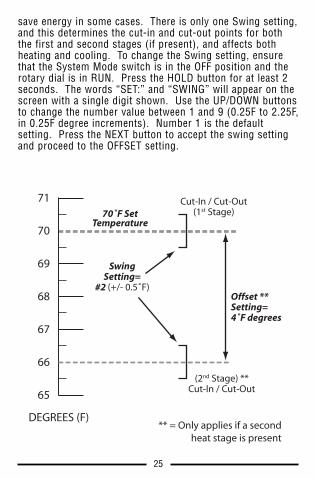
SWING AND OFFSET SETTINGS
SWING: A thermostat works by turning your heating orcooling system on and off whenever the room temperaturevaries from the set-point temperature. The amount of thisvariation is called the swing. Your system should cycle onabout 3 to 6 times per hour. A smaller swing numberincreases the number of cycles per hour, so the roomtemperature is more precise and constant. A larger swingnumber decreases the number of cycles per hour, but can
25
save energy in some cases. There is only one Swing setting,and this determines the cut-in and cut-out points for boththe first and second stages (if present), and affects bothheating and cooling. To change the Swing setting, ensurethat the System Mode switch is in the OFF position and therotary dial is in RUN. Press the HOLD button for at least 2seconds. The words “SET:” and “SWING” will appear on thescreen with a single digit shown. Use the UP/DOWN buttonsto change the number value between 1 and 9 (0.25F to 2.25F,in 0.25F degree increments). Number 1 is the defaultsetting. Press the NEXT button to accept the swing settingand proceed to the OFFSET setting.
70˚F SetTemperature
71
DEGREES (F)** = Only applies if a second
heat stage is present
70
69
68
67
66
65
SwingSetting=
#2 (+/- 0.5˚F)
Cut-In / Cut-Out(1st Stage)
(2nd Stage) **Cut-In / Cut-Out
Offset **Setting=4˚F degrees

26
OFFSET: After the swing value has been accepted, the words“SET:” and “OFFSET” will be shown on the screen. Thissetting is shown as a number of degrees, and is similar innature to the swing however it only effects the operation ofthe second (auxiliary) heating stage, if present. The settingrange for Offset is from 0 to 9 degrees. When set to 0degrees, the second heating stage is disabled. A value from1 to 9 degrees will determine the number of degrees fromthe set point that will be required for the second heatingstage to turn on. This setting can be used to conserveenergy in cases where the second heating stage is costly tooperate when compared to the first stage.
USER TEMPERATURE CALIBRATIONThe internal temperature sensor in this thermostat isaccurately calibrated at the factory and should not need to beadjusted. The Temperature Calibration feature allows you tomanually offset the measured temperature by as much asplus or minus 5°F (3°C) degrees from its original value.This feature can be useful to match this thermostat toanother one or more, if multiple thermostats are used in thesame home. To change the Temperature Calibration: ensurethat the System Mode switch is in the OFF position, and therotary dial is in RUN. Press the COPY/EMER button for atleast 2 seconds. The words “SET:” and “CAL” will appear onthe screen with a single temperature digit shown. Use theUP/DOWN buttons to change the number of degrees ofadjustment. 0° degrees is the default value. Press the NEXTbutton to accept the setting.
PROGRAMMABLE KEYPAD LOCKNOTE: The following examples use the default lock code of“0000”. If you have altered the lock code to use your owncode, use that in place of “0000” in the followinginstructions.
To prevent tampering with any of your settings, the frontpanel buttons and rotary dial can be locked out, requiring a

27
four-digit code to unlock them. You may use either thedefault lock code of “0000”, or your own code number (see“TO CHANGE THE LOCK CODE:”).
TO LOCK THE THERMOSTAT: Ensure the rotary dial is in theRUN position. Press the NEXT button for at least 2 seconds.The words “ENTER CODE” will appear on the screen, above“0000”. Enter the correct code by using the UP/DOWNbuttons to change the flashing digit, and the NEXT button toadvance to the next digit. Press the NEXT button again forat least 2 seconds. A padlock should appear on the screento confirm that the thermostat is now locked.
TO UNLOCK THE THERMOSTAT: Ensure the rotary dial is inthe RUN position. A single press of any button will causethe words “ENTER CODE” to appear on the screen, above“0000”. Enter the correct code by using the UP/DOWNbuttons to change the flashing digit, and the NEXT button toadvance to the next digit. Press the NEXT button again forat least 2 seconds. The padlock should disappear, and thethermostat should now be unlocked.
If you try to unlock the thermostat by entering a code that isnot correct, a padlock and the digits “88:88” will flash on thescreen and you will have to try again to enter the correctcode. If a different lock code was used other than thedefault of “0000”, this will need to be entered by using theUP/DOWN buttons, and the NEXT button to advance to thenext digit. Once the correct code is entered, press the NEXTbutton for at least 2 seconds. The padlock should disappear,and the thermostat should now be unlocked.
5:36 72HEAT
TUDAY
F
PM

28
TO CHANGE THE LOCK CODE: First ensure that thethermostat is unlocked and the rotary dial is in the RUNposition. Press the NEXT button for at least 2 seconds. Thewords “ENTER CODE” will appear on the screen, above“0000”. Now press the HOLD button for at least 2 seconds.The words “SET CODE” will appear on the screen, along with“0000”. Enter your desired code by using the UP/DOWNbuttons to change the flashing digit, and the NEXT button toadvance to the next digit. Press the NEXT button again forat least 2 seconds. Enter your new code to lock thethermostat, or you may wait for 12 seconds to exitautomatically without locking the thermostat.
IF YOU HAVE FORGOTTEN YOUR LOCK CODE: You can resetthe code to “0000” and then unlock the thermostat. On theback of thermostat, locate JP1, which is a row of 3 gold pinsat the right edge of the circuit board above the battery tray.There should be a plastic jumper cap on 2 of the 3 pins(either right or left).
Remove the jumper cap, and place it on the opposite 2 pins.Move the Temperature Mode switch on the front to any otherposition than its current one. The lock code should now bethe default of “0000”, but still be in a locked state. Followthe instructions listed in “UNLOCKING THE THERMOSTAT”,and use the “0000” when entering the code.
JP1
Kurt
Rectangle
29
13. PROGRAMMING
SET HEAT PROGRAMRotate the dial to HEAT PROGRAM. You will beprogramming the heat periods for all seven days, one afterthe other starting with Monday. The first period is MORN.Using the UP and DOWN buttons, set the start time for thisperiod, and then push the NEXT button to proceed. Now setthe desired set temperature for the MORN period using theUP and DOWN buttons, and push NEXT to proceed. Now setthe start time and set temperature for the DAY period,pushing NEXT after each to advance. Continue with thesesame steps to set the start time and set temperature for theEVE, and NITE program periods.
When you are finished setting all four periods, you maycontinue pushing the NEXT button through all four periods ofTuesday, Wednesday, and so on. Once you have reached theSunday NITE period, you have completed all of the heatprograms. To review your entries, keep pressing the NEXTbutton through the four periods of every day, or turn the dialto RUN if you are finished.
SET COOL PROGRAMRotate the dial to COOL PROGRAM. You will beprogramming the cool periods for all seven days, one afterthe other starting with Monday. You will begin with the starttime of the MORN period, and use the same procedures thatwere performed while setting the HEAT PROGRAM periodsdescribed above, using the NEXT button to advance throughthe values. Return the dial to the RUN position when youare finished.
QUICK COPY FEATUREThe Copy feature allows you to copy all of the programinformation from any one single day, to any other day. Withthe rotary dial in either HEAT PROGRAM or COOLPROGRAM, press the COPY button once. The words “COPY”

30
will appear on the screen, with one of the days flashingabove. Using the UP/DOWN buttons, select the day that youwant to copy from. Press the NEXT button once. Your“copy from” day should be on steady with the following dayflashing. Use the UP/DOWN buttons to select the day thatyou would like to copy to. A single short press of the COPYbutton will perform the copy, and the flashing day willadvance to the next following day. You may continue toperform short single presses of the COPY button to alsocopy to the remaining days, one after the other (certain daysmay be skipped by pressing the UP button to advance pastthem). To exit the Copy feature, and return to theprogramming screen, press and hold the NEXT button formore than 1 second.
14. BATTERIES AND MAINTENANCE
This thermostat can be powered by either two “AA” alkalinebatteries, a 24VAC common wire from your heating orcooling system, or a combination of both. If you are usingeither batteries alone, or a combination of 24VAC systempower with batteries as a backup, the batteries should bereplaced AT LEAST once per year, or sooner if the “LOWBAT” battery symbol appears in the lower left portion of thedisplay screen as shown below.
To replace the batteries in the thermostat, remove thethermostat’s body from the base plate attached to the wall bypressing the thumb latch at the bottom center of the unit and
5:36 72HEAT
TUDAY
F
PMLOW BAT

31
swinging the body towards you, up and away from the base.Remove the used batteries from the battery tray and discardappropriately.
Install two new Energizer® or DURACELL® “AA” size alkalinebatteries into the battery tray. Observe the polarity markingsshown in the battery compartment to ensure properinstallation. When finished, hang the top of the unit by thetabs at the top corners of the base, and then snap thebottom of the unit into place. Do not use unnecessary force.If the body does not snap into place easily, remove the body,re-hang it from the tabs and try again.
15. TECHNICAL ASSISTANCE
If you have any problems installing or using this thermostat,please carefully and thoroughly review the instructionmanual. If you require assistance, please contact ourTechnical Assistance department at 856-234-8803 duringregular business hours between 8:00AM and 4:30PM EasternStandard Time, Monday through Friday. You can also receivetechnical assistance online anytime day or night athttp://www.luxproducts.com. Our web site offers youanswers to the most common technical questions, and alsopermits you to email your questions to our technical supportstaff at your convenience.
16. WARRANTY
Limited Warranty: If this unit fails because of defects inmaterials or workmanship within three years of the date oforiginal purchase, LUX will, at its option, repair or replace it.This warranty does not cover damage by accident, misuse,or failure to follow installation instructions. Impliedwarranties are limited in duration to three years from thedate of original purchase. Some states do not allow

Mt. Laurel, New Jersey 08054, USAhttp://www.luxproproducts.com
5:36 72HEAT
TUDAY
F
PM
limitations on how long an implied warranty lasts, so theabove limitation may not apply to you. Please returnmalfunctioning or defective units to the location from whichthe purchase was made, along with proof of purchase.Please refer to "TECHNICAL ASSISTANCE" before returningthermostat. Purchaser assumes all risks and liability forincidental and consequential damage resulting frominstallation and use of this unit. Some states do not allowthe exclusion of incidental or consequential damages, so theabove exclusion may not apply to you. This warranty givesyou specific legal rights and you may also have other rightswhich vary from state to state. Applicable in the U.S.A. andCanada only.