tx³ - prong and fork type busbars
20
NEW TX³ RANGE TRUSTED PROTECTION FOR YOUR INSTALLATIONS GLOBAL SPECIALIST IN ELECTRICAL AND DIGITAL BUILDING INFRASTRUCTURES
Transcript of tx³ - prong and fork type busbars
NEW TX³ RANGE TRUSTED PROTECTION FOR YOUR INSTALLATIONS
GLOBAL SPECIALIST IN ELECTRICAL ANDDIGITAL BUILDING INFRASTRUCTURES
TX³TX³ RANGE RANGETRUSTED PROTECTION FOR YOUR INSTALLATIONS

Designed to meet the requirements
of modern installations in residential and
commercial applications, Legrand’s new TX³ range
provides effective protection against short-circuits,
overloads and residual current faults. The range,
which comprises thermal-magnetic circuit breakers
and residualcurrent devices
and is complemented by numerous control
and signalling auxiliaries, ensures safety, ruggedness
and a high build quality for your installations.
RCCBs• In = from 16 to 80 A• 2P and 4P (neutral on right-hand side)• Type AC and A• Sensitivity: 30, 100, 300 mA• Compliant with IEC 61 008-1
NEW TX³ RANGEPROTECTION YOU CAN RELY ON

NEW TX³ RANGEWWW.LEGRAND.COM
1
NEW TX³ RANGEPROTECTION YOU CAN RELY ON
Common auxiliariesLegrand offers a wide range of control and signalling auxiliaries common for all circuit breakers and RCCBs in the TX³ and DX³ ranges.For more information, see p. 6
THERMAL-MAGNETIC CIRCUIT BREAKERS• In = 2 to 63 A• 1P to 4P• B and C curves• Breaking capacity: 6 000 A and 10 000 A at 230/400V A• Compliant with IEC 60 898-1

2
The new TX³ range ensures safe installation
and operation for maximum protection
of people and property.
WIRE GUIDE FLAPAvoids connection errors for an increased safety level, by preventing insertion of the wire behind the terminal.
TX³ - SAFETYON ALL LEVELS
A PRODUCT DESIGNEDWITH SAFETY IN MINDThe product design and materialshave been carefully developedto allow air to flow freely betweeneach device to avoid overheating.
AIR
FLOW
NEW TX³ RANGEWWW.LEGRAND.COM
3
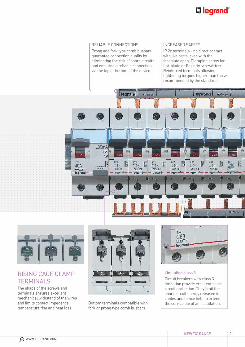
RISING CAGE CLAMP TERMINALSThe shape of the screws and terminals ensures excellent mechanical withstand of the wires and limits contact impedance, temperature rise and heat loss.
Limitation class 3Circuit breakers with class 3 limitation provide excellent short-circuit protection. They limit the short-circuit energy released in cables and hence help to extend the service life of an installation.
RELIABLE CONNECTIONSProng and fork type comb busbars guarantee connection quality by eliminating the risk of short-circuits and ensuring a reliable connection via the top or bottom of the device.
INCREASED SAFETYIP 2x terminals - no direct contact with live parts, even with the faceplate open. Clamping screw for flat-blade or Pozidriv screwdriver. Reinforced terminals allowing tightening torques higher than those recommended by the standard.
Bottom terminals compatible with fork or prong type comb busbars.

4
For ease of installation, wiring and maintenance,
the new TX³ range has a number of features which help save time
at each stage of a project.
TX³ - INSTALLATION AND MAINTENANCE
MADE EASY
CLEAR MARKING ON THE FRONT PANELFor quick visual identification of the relevant information - product name, curve type, rating, breaking capacity, limitation class.
TECHNICAL LABELLING AREAFor quick identification of each circuit according to the wiring diagram. The surface of this part of the modular devices has been specially treated to receive a temporary marking (adhesive label, felt pen or pencil).
NEW TX³ RANGEWWW.LEGRAND.COM
5
TX³ - INSTALLATION AND MAINTENANCE
MADE EASY
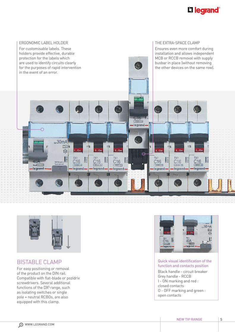
Quick visual identification of the function and contacts positionBlack handle - circuit breakerGrey handle - RCCBI - ON marking and red : closed contactsO - OFF marking and green : open contacts
BISTABLE CLAMPFor easy positioning or removal of the product on the DIN rail. Compatible with flat-blade or pozidriv screwdrivers. Several additional functions of the DX3 range, such as isolating switches or single pole + neutral RCBOs, are also equipped with this clamp.
ERGONOMIC LABEL HOLDERFor customisable labels. These holders provide effective, durableprotection for the labels which are used to identify circuits clearly for the purposes of rapid intervention in the event of an error.
THE EXTRA-SPACE CLAMPEnsures even more comfort during installation and allows independent MCB or RCCB removal with supply busbar in place (without removing the other devices on the same row).

6
Legrand offers a wide range of control and signalling auxiliaries for TX³ circuit breakers and RCCBs to
monitor and control circuits remotely. These auxiliaries
are used for remote control and information feedback
purposes in commercial premises and are also
common to the DX³ range.
AUXILIARIES - OFFERING FLEXIBILITY FOR YOUR INSTALLATIONS
TOTAL FLEXIBILITYAuxiliary contacts and fault signal contacts, shunt trips, undervoltage releases and motor-driven controls. Available in 0.5 or 1 module wide. The signalling auxiliaries exist in 2 versions, adapted for fork-type respectively prong-type supply busbars.
NEW TX³ RANGEWWW.LEGRAND.COM
7
AUXILIARIES - OFFERING FLEXIBILITY FOR YOUR INSTALLATIONS
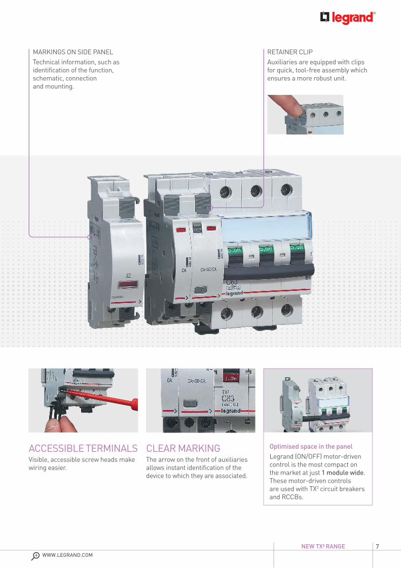
ACCESSIBLE TERMINALSVisible, accessible screw heads make wiring easier.
CLEAR MARKINGThe arrow on the front of auxiliaries allows instant identification of the device to which they are associated.
MARKINGS ON SIDE PANELTechnical information, such as identification of the function, schematic, connection and mounting.
RETAINER CLIPAuxiliaries are equipped with clips for quick, tool-free assembly which ensures a more robust unit.
à shooter à shooter
Optimised space in the panelLegrand (ON/OFF) motor-driven control is the most compact on the market at just 1 module wide. These motor-driven controls are used with TX3 circuit breakers and RCCBs.

88
At Legrand, we take pride in the quality of our products. The TX³ range
has many approvals issued by independent
certification bodies, renowned for their strict
requirements.
Rugged reliability
ECO-FRIENDLYThe TX³ range has been designed to comply with different environmental requirements such as the RoHS Directive.
TX³ - HIGH BUILD QUALITY AND ENVIRONMENTALLY-
FRIENDLY
- 25°C to + 70°C Extreme operating conditions
10,000 operations with loadElectrical endurance
NEW TX³ RANGEWWW.LEGRAND.COM
99
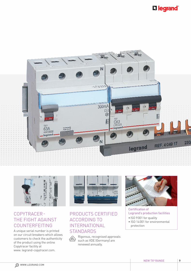
COPYTRACER - THE FIGHT AGAINST COUNTERFEITINGA unique serial number is printedon our circuit breakers which allowscustomers to check the authenticity of the product using the online Copytracer facility at www. legrand-copytracer.com.
PRODUCTS CERTIFIED ACCORDING TOINTERNATIONAL STANDARDS
Rigorous, recognised approvals such as VDE (Germany) are renewed annually.
TX³ - HIGH BUILD QUALITY AND ENVIRONMENTALLY-
FRIENDLY
Certification of Legrand’s production facilities• ISO 9 001 for quality• ISO 14 001 for environmental
protection
VDE(Allemagne)
10
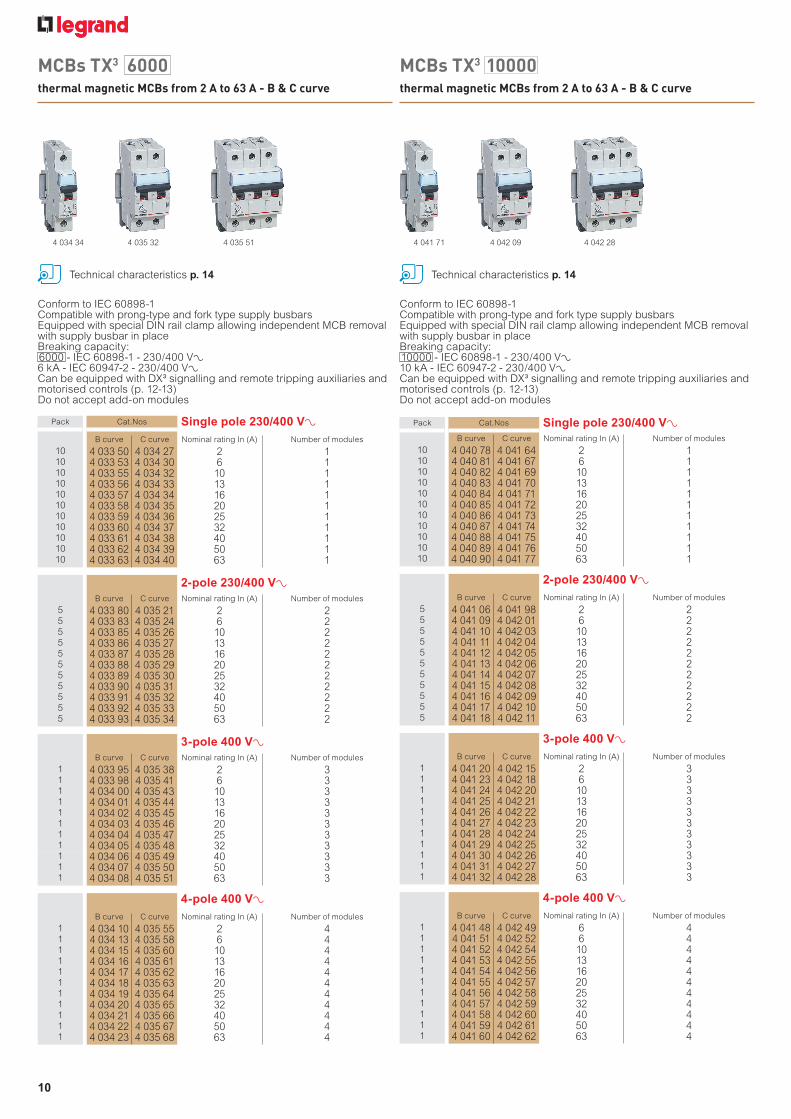
MCBs TX3 6000
thermal magnetic MCBs from 2 A to 63 A - B & C curve
MCBs TX3 10000
thermal magnetic MCBs from 2 A to 63 A - B & C curve
Pack Cat.Nos Single pole 230/400 V±B curve C curve Nominal rating In (A) Number of modules
10 4 033 50 4 034 27 2 110 4 033 53 4 034 30 6 110 4 033 55 4 034 32 10 110 4 033 56 4 034 33 13 110 4 033 57 4 034 34 16 110 4 033 58 4 034 35 20 110 4 033 59 4 034 36 25 110 4 033 60 4 034 37 32 110 4 033 61 4 034 38 40 110 4 033 62 4 034 39 50 110 4 033 63 4 034 40 63 1
2-pole 230/400 V±B curve C curve Nominal rating In (A) Number of modules
5 4 033 80 4 035 21 2 25 4 033 83 4 035 24 6 25 4 033 85 4 035 26 10 25 4 033 86 4 035 27 13 25 4 033 87 4 035 28 16 25 4 033 88 4 035 29 20 25 4 033 89 4 035 30 25 25 4 033 90 4 035 31 32 25 4 033 91 4 035 32 40 25 4 033 92 4 035 33 50 25 4 033 93 4 035 34 63 2
3-pole 400 V±B curve C curve Nominal rating In (A) Number of modules
1 4 033 95 4 035 38 2 31 4 033 98 4 035 41 6 31 4 034 00 4 035 43 10 31 4 034 01 4 035 44 13 31 4 034 02 4 035 45 16 31 4 034 03 4 035 46 20 31 4 034 04 4 035 47 25 31 4 034 05 4 035 48 32 31 4 034 06 4 035 49 40 31 4 034 07 4 035 50 50 31 4 034 08 4 035 51 63 3
4-pole 400 V±B curve C curve Nominal rating In (A) Number of modules
1 4 034 10 4 035 55 2 41 4 034 13 4 035 58 6 41 4 034 15 4 035 60 10 41 4 034 16 4 035 61 13 41 4 034 17 4 035 62 16 41 4 034 18 4 035 63 20 41 4 034 19 4 035 64 25 41 4 034 20 4 035 65 32 41 4 034 21 4 035 66 40 41 4 034 22 4 035 67 50 41 4 034 23 4 035 68 63 4
Pack Cat.Nos Single pole 230/400 V±B curve C curve Nominal rating In (A) Number of modules
10 4 040 78 4 041 64 2 110 4 040 81 4 041 67 6 110 4 040 82 4 041 69 10 110 4 040 83 4 041 70 13 110 4 040 84 4 041 71 16 110 4 040 85 4 041 72 20 110 4 040 86 4 041 73 25 110 4 040 87 4 041 74 32 110 4 040 88 4 041 75 40 110 4 040 89 4 041 76 50 110 4 040 90 4 041 77 63 1
2-pole 230/400 V±B curve C curve Nominal rating In (A) Number of modules
5 4 041 06 4 041 98 2 25 4 041 09 4 042 01 6 25 4 041 10 4 042 03 10 25 4 041 11 4 042 04 13 25 4 041 12 4 042 05 16 25 4 041 13 4 042 06 20 25 4 041 14 4 042 07 25 25 4 041 15 4 042 08 32 25 4 041 16 4 042 09 40 25 4 041 17 4 042 10 50 25 4 041 18 4 042 11 63 2
3-pole 400 V±B curve C curve Nominal rating In (A) Number of modules
1 4 041 20 4 042 15 2 31 4 041 23 4 042 18 6 31 4 041 24 4 042 20 10 31 4 041 25 4 042 21 13 31 4 041 26 4 042 22 16 31 4 041 27 4 042 23 20 31 4 041 28 4 042 24 25 31 4 041 29 4 042 25 32 31 4 041 30 4 042 26 40 31 4 041 31 4 042 27 50 31 4 041 32 4 042 28 63 3
4-pole 400 V±B curve C curve Nominal rating In (A) Number of modules
1 4 041 48 4 042 49 6 41 4 041 51 4 042 52 6 41 4 041 52 4 042 54 10 41 4 041 53 4 042 55 13 41 4 041 54 4 042 56 16 41 4 041 55 4 042 57 20 41 4 041 56 4 042 58 25 41 4 041 57 4 042 59 32 41 4 041 58 4 042 60 40 41 4 041 59 4 042 61 50 41 4 041 60 4 042 62 63 4
Conform to IEC 60898-1Compatible with prong-type and fork type supply busbars Equipped with special DIN rail clamp allowing independent MCB removal with supply busbar in place Breaking capacity:6000 - IEC 60898-1 - 230/400 V±6 kA - IEC 60947-2 - 230/400 V±Can be equipped with DX³ signalling and remote tripping auxiliaries and motorised controls (p. 12-13)Do not accept add-on modules
Conform to IEC 60898-1Compatible with prong-type and fork type supply busbarsEquipped with special DIN rail clamp allowing independent MCB removal with supply busbar in place Breaking capacity:10000 - IEC 60898-1 - 230/400 V±10 kA - IEC 60947-2 - 230/400 V±Can be equipped with DX³ signalling and remote tripping auxiliaries and motorised controls (p. 12-13)Do not accept add-on modules
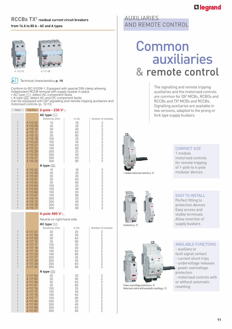
Technical characteristics p. 14
4 034 34 4 035 32 4 035 51 4 041 71 4 042 09 4 042 28
Technical characteristics p. 14
11
for example : xxxxxxxTM
xxxxxxxx
RCCBs TX3 residual current circuit breakers
from 16 A to 80 A - AC and A types
Pack Cat.Nos 2-pole - 230 V±AC type ?
Sensitivity (mA) In (A) Number of modules
1 4 115 02 10 16 21 4 115 09 30 25 21 4 115 10 30 40 21 4 115 11 30 63 21 4 115 12 30 80 21 4 115 19 100 25 21 4 115 20 100 40 21 4 115 21 100 63 21 4 115 22 100 80 21 4 115 29 300 25 21 4 115 30 300 40 21 4 115 31 300 63 21 4 115 32 300 80 2
A type M1 4 115 52 10 16 21 4 115 59 30 25 21 4 115 60 30 40 21 4 115 61 30 63 21 4 115 62 30 80 21 4 115 64 100 25 21 4 115 65 100 40 21 4 115 66 100 63 21 4 115 67 100 80 21 4 115 74 300 25 21 4 115 75 300 40 21 4 115 76 300 63 21 4 115 77 300 80 2
4-pole 400 V±Neutral on right-hand side
AC type ?Sensitivity (mA) In (A) Number of modules
1 4 117 07 30 25 21 4 117 08 30 40 21 4 117 09 30 63 21 4 117 10 30 80 21 4 117 17 100 25 21 4 117 18 100 40 21 4 117 19 100 63 21 4 117 20 100 80 21 4 117 27 300 25 21 4 117 28 300 40 21 4 117 29 300 63 21 4 117 30 300 80 2
A type M1 4 117 64 30 25 21 4 117 65 30 40 21 4 117 66 30 63 21 4 117 67 30 80 21 4 117 74 100 25 21 4 117 75 100 40 21 4 117 76 100 63 21 4 117 77 100 80 21 4 117 84 300 25 21 4 117 85 300 40 21 4 117 86 300 63 21 4 117 87 300 80 2
Conform to IEC 61008-1. Equipped with special DIN clamp allowing independent RCCB removal with supply busbar in place• AC type ?: detect AC component faults• A type M: detect AC and DC component faults Can be equipped with DX³ signalling and remote tripping auxiliaries and motorised controls (p. 12-13)
Technical characteristics p. 14
4 115 10 4 117 09
AUXILIARIES AND REMOTE CONTROL
COMPACT SIZE1 module motorised controls for remote tripping of 1-pole to 4-pole modular devices.1 module motorised controls p. 13
AVAILABLE FUNCTIONS- auxiliary or fault signal contact- current shunt trips- undervoltage releases- power overvoltage protection- motorised controls with or without automatic resetting
EASY TO INSTALLPerfect fitting to protection devicesEasy access and visible terminalsAllow insertion of supply busbars
The signalling and remote tripping auxiliaries and the motorised controls are common for DX3 MCBs, RCBOs and RCCBs and TX³ MCBs and RCCBs.Signalling auxiliaries are available in two versions, adapted to the prong or fork type supply busbars.
Commonauxiliaries
& remote control
Power overvoltage protection p. 12Motorised control with automatic resetting p. 13
Auxiliaries p. 12
1212
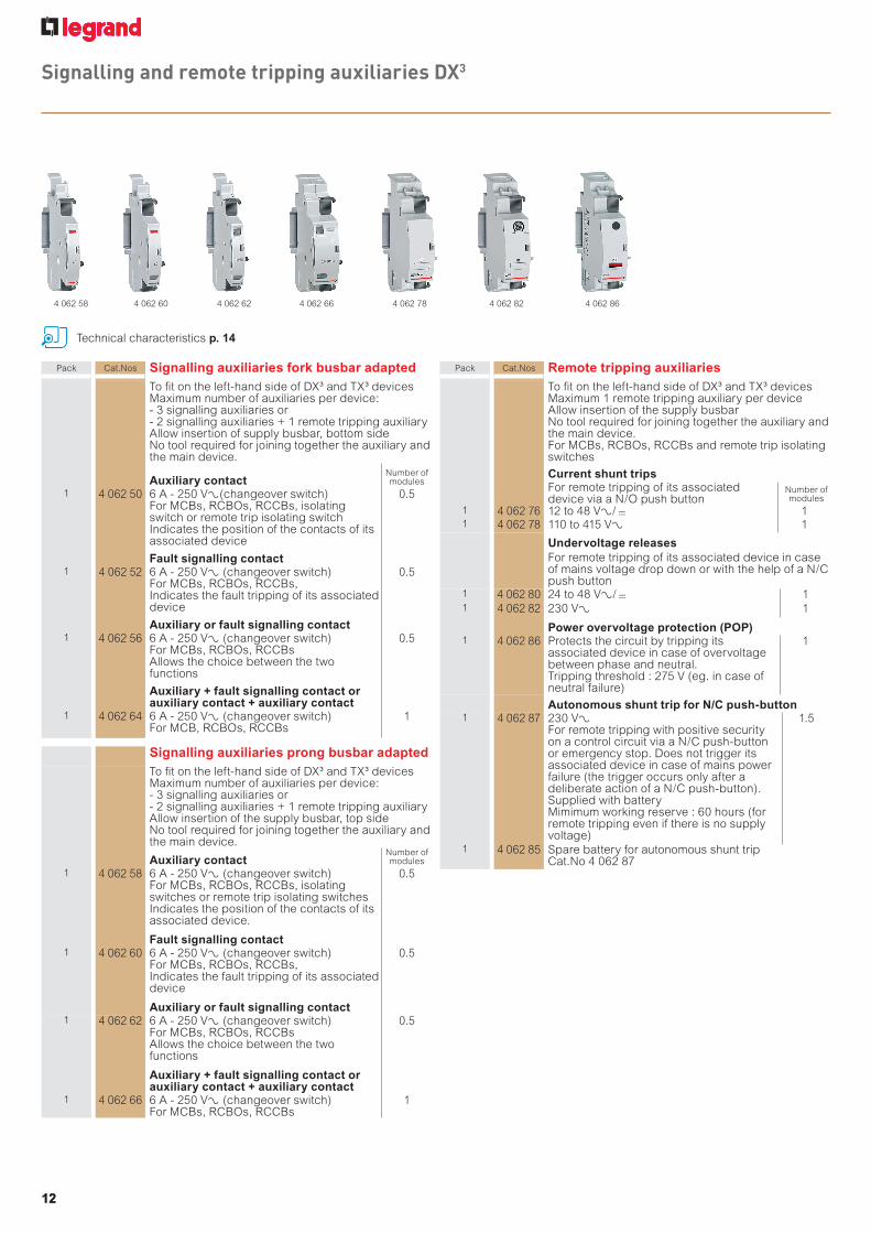
Signalling and remote tripping auxiliaries DX3
Pack Cat.Nos Signalling auxiliaries fork busbar adaptedTo fit on the left-hand side of DX³ and TX³ devicesMaximum number of auxiliaries per device: - 3 signalling auxiliaries or - 2 signalling auxiliaries + 1 remote tripping auxiliary Allow insertion of supply busbar, bottom sideNo tool required for joining together the auxiliary and the main device.
Auxiliary contact Number of modules
1 4 062 50 6 A - 250 VA(changeover switch) For MCBs, RCBOs, RCCBs, isolating switch or remote trip isolating switchIndicates the position of the contacts of its associated device
0.5
Fault signalling contact1 4 062 52 6 A - 250 VA (changeover switch)
For MCBs, RCBOs, RCCBs,Indicates the fault tripping of its associated device
0.5
Auxiliary or fault signalling contact1 4 062 56 6 A - 250 VA (changeover switch)
For MCBs, RCBOs, RCCBsAllows the choice between the two functions
0.5
Auxiliary + fault signalling contact or auxiliary contact + auxiliary contact
1 4 062 64 6 A - 250 VA (changeover switch)For MCB, RCBOs, RCCBs
1
Signalling auxiliaries prong busbar adaptedTo fit on the left-hand side of DX³ and TX³ devicesMaximum number of auxiliaries per device: - 3 signalling auxiliaries or - 2 signalling auxiliaries + 1 remote tripping auxiliary Allow insertion of the supply busbar, top sideNo tool required for joining together the auxiliary and the main device.
Auxiliary contact Number of modules
1 4 062 58 6 A - 250 VA (changeover switch) For MCBs, RCBOs, RCCBs, isolating switches or remote trip isolating switchesIndicates the position of the contacts of its associated device.
0.5
Fault signalling contact1 4 062 60 6 A - 250 VA (changeover switch)
For MCBs, RCBOs, RCCBs,Indicates the fault tripping of its associated device
0.5
Auxiliary or fault signalling contact1 4 062 62 6 A - 250 VA (changeover switch)
For MCBs, RCBOs, RCCBsAllows the choice between the two functions
0.5
Auxiliary + fault signalling contact or auxiliary contact + auxiliary contact
1 4 062 66 6 A - 250 VA (changeover switch)For MCBs, RCBOs, RCCBs
1
Pack Cat.Nos Remote tripping auxiliariesTo fit on the left-hand side of DX³ and TX³ devicesMaximum 1 remote tripping auxiliary per device Allow insertion of the supply busbarNo tool required for joining together the auxiliary and the main device.For MCBs, RCBOs, RCCBs and remote trip isolating switches
Current shunt tripsFor remote tripping of its associated device via a N/O push button
Number of modules
1 4 062 76 12 to 48 VA/ = 11 4 062 78 110 to 415 VA 1
Undervoltage releasesFor remote tripping of its associated device in case of mains voltage drop down or with the help of a N/C push button
1 4 062 80 24 to 48 VA/ = 11 4 062 82 230 VA 1
Power overvoltage protection (POP)1 4 062 86 Protects the circuit by tripping its
associated device in case of overvoltage between phase and neutral.Tripping threshold : 275 V (eg. in case of neutral failure)
1
Autonomous shunt trip for N/C push-button 1 4 062 87 230 VA
For remote tripping with positive security on a control circuit via a N/C push-button or emergency stop. Does not trigger its associated device in case of mains power failure (the trigger occurs only after a deliberate action of a N/C push-button).Supplied with batteryMimimum working reserve : 60 hours (for remote tripping even if there is no supply voltage)
1.5
1 4 062 85 Spare battery for autonomous shunt trip Cat.No 4 062 87
4 062 60 4 062 62 4 062 664 062 58 4 062 78 4 062 82 4 062 86
Technical characteristics p. 14
1313
for example : xxxxxxxTM
xxxxxxxx
for example : xxxxxxxTM
xxxxxxxx
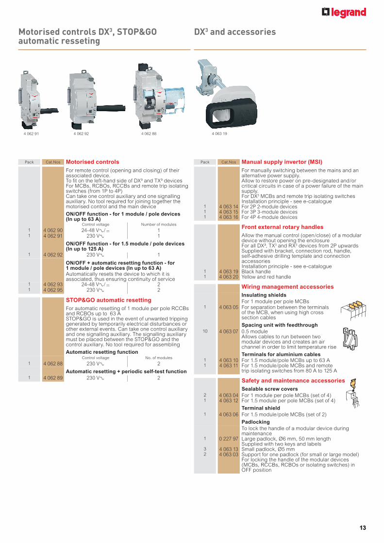
Motorised controls DX3, STOP&GO automatic resseting
DX3 and accessories
4 062 91 4 062 92 4 062 88
Pack Cat.Nos Motorised controlsFor remote control (opening and closing) of their associated device. To fit on the left-hand side of DX³ and TX³ devicesFor MCBs, RCBOs, RCCBs and remote trip isolating switches (from 1P to 4P)Can take one control auxiliary and one signalling auxiliary. No tool required for joining together the motorised control and the main device
ON/OFF function - for 1 module / pole devices (In up to 63 A)
Control voltage Number of modules
1 4 062 90 24-48 VA/ = 11 4 062 91 230 VA 1
ON/OFF function - for 1.5 module / pole devices (In up to 125 A)
1 4 062 92 230 VA 1
ON/OFF + automatic resetting function - for 1 module / pole devices (In up to 63 A)Automatically resets the device to which it is associated, thus ensuring continuity of service
1 4 062 93 24-48 VA/ = 21 4 062 95 230 VA 2
STOP&GO automatic resettingFor automatic resetting of 1 module per pole RCCBs and RCBOs up to 63 A STOP&GO is used in the event of unwanted tripping generated by temporarily electrical disturbances or other external events. Can take one control auxiliary and one signalling auxiliary. The signalling auxiliary must be placed between the STOP&GO and the control auxiliary. No tool required for assembling
Automatic resetting functionControl voltage No. of modules
1 4 062 88 230 VA 2
Automatic resetting + periodic self-test function1 4 062 89 230 VA 2
Pack Cat.Nos Manual supply invertor (MSI)For manually switching between the mains and an alternative power supply.Allow to restore power on pre-designated and/or critical circuits in case of a power failure of the main supply.For DX3 MCBs and remote trip isolating switchesInstallation principle - see e-catalogue
1 4 063 14 For 2P 2-module devices1 4 063 15 For 3P 3-module devices1 4 063 16 For 4P 4-module devices
Front external rotary handlesAllow the manual control (open/close) of a modular device without opening the enclosureFor all DX³, TX3 and RX3 devices from 2P upwardsSupplied with bracket, connection rod, handle, self-adhesive drilling template and connection accessoriesInstallation principle - see e-catalogue
1 4 063 19 Black handle1 4 063 20 Yellow and red handle
Wiring management accessoriesInsulating shieldsFor 1 module per pole MCBs
1 4 063 05 For separation between the terminals of the MCB, when using high cross section cables
Spacing unit with feedthrough10 4 063 07 0.5 module
Allows cables to run between two modular devices and creates an air channel in order to limit temperature rise
Terminals for aluminium cables1 4 063 10 For 1.5 module/pole MCBs up to 63 A1 4 063 11 For 1.5 module/pole MCBs and remote
trip isolating switches from 80 A to 125 A
Safety and maintenance accessoriesSealable screw covers
2 4 063 04 For 1 module per pole MCBs (set of 4)1 4 063 12 For 1.5 module per pole MCBs (set of 4)
Terminal shield1 4 063 06 For 1.5 module/pole MCBs (set of 2)
PadlockingTo lock the handle of a modular device during maintenance
1 0 227 97 Large padlock, Ø6 mm, 50 mm length Supplied with two keys and labels
3 4 063 13 Small padlock, Ø5 mm2 4 063 03 Support for one padlock (for small or large model)
For locking the handle of the modular devices (MCBs, RCCBs, RCBOs or isolating switches) in OFF position
4 063 19
14
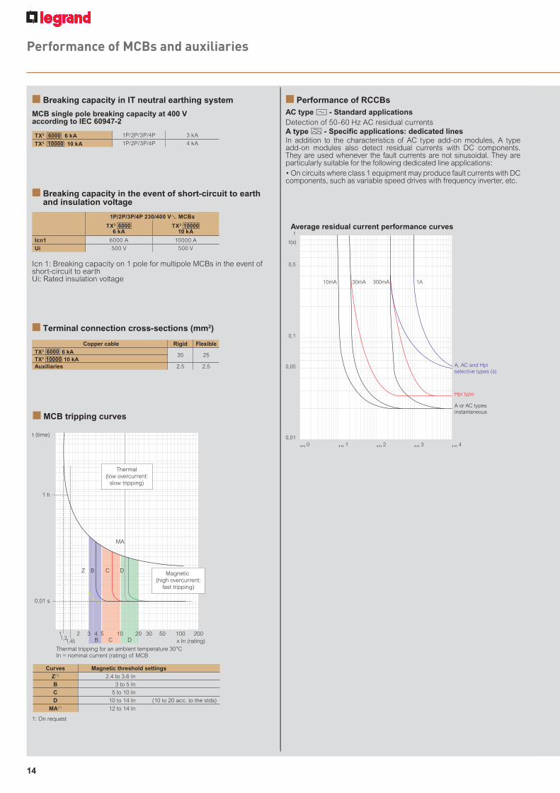
Performance of MCBs and auxiliaries
n Breaking capacity in IT neutral earthing system
MCB single pole breaking capacity at 400 V according to IEC 60947-2
TX3 6000 6 kA 1P/2P/3P/4P 3 kA
TX3 10000 10 kA 1P/2P/3P/4P 4 kA
n Breaking capacity in the event of short-circuit to earth and insulation voltage
Icn 1: Breaking capacity on 1 pole for multipole MCBs in the event of short-circuit to earthUi: Rated insulation voltage
1P/2P/3P/4P 230/400 VA MCBs
TX3 6000 6 kA
TX3 10000 10 kA
Icn1 6000 A 10000 A
Ui 500 V 500 V
1: On request
Curves Magnetic threshold settingsZ(1) 2.4 to 3.6 In
B 3 to 5 In
C 5 to 10 In
D 10 to 14 In (10 to 20 acc. to the stds)
MA(1) 12 to 14 In
n Terminal connection cross-sections (mm2)
Copper cable Rigid FlexibleTX3 6000 6 kA
35 25TX3 10000 10 kAAuxiliaries 2.5 2.5
n MCB tripping curves
11,31,45
3 4 5 10 20 30 50 100 200x In (rating)
Thermal tripping for an ambient temperature 30°CIn = nominal current (rating) of MCB
Magnetic (high overcurrent:
fast tripping)
MA
DCB
DCB
Z
Thermal(low overcurrent:
slow tripping)
2
0,01 s
1 h
t (time)
10 410 310 210 110 00,01
0,05
0,1
0,5
10mA 30mA 300mA 1A
t(s)
I ∆ (mA)
1
A, AC and Hpiselective types (s)
A or AC types instantaneous
Hpi type
n Performance of RCCBsAC type ? - Standard applicationsDetection of 50-60 Hz AC residual currentsA type M - Specific applications: dedicated linesIn addition to the characteristics of AC type add-on modules, A type add-on modules also detect residual currents with DC components. They are used whenever the fault currents are not sinusoidal. They are particularly suitable for the following dedicated line applications:• On circuits where class 1 equipment may produce fault currents with DC components, such as variable speed drives with frequency inverter, etc.
Average residual current performance curves
15
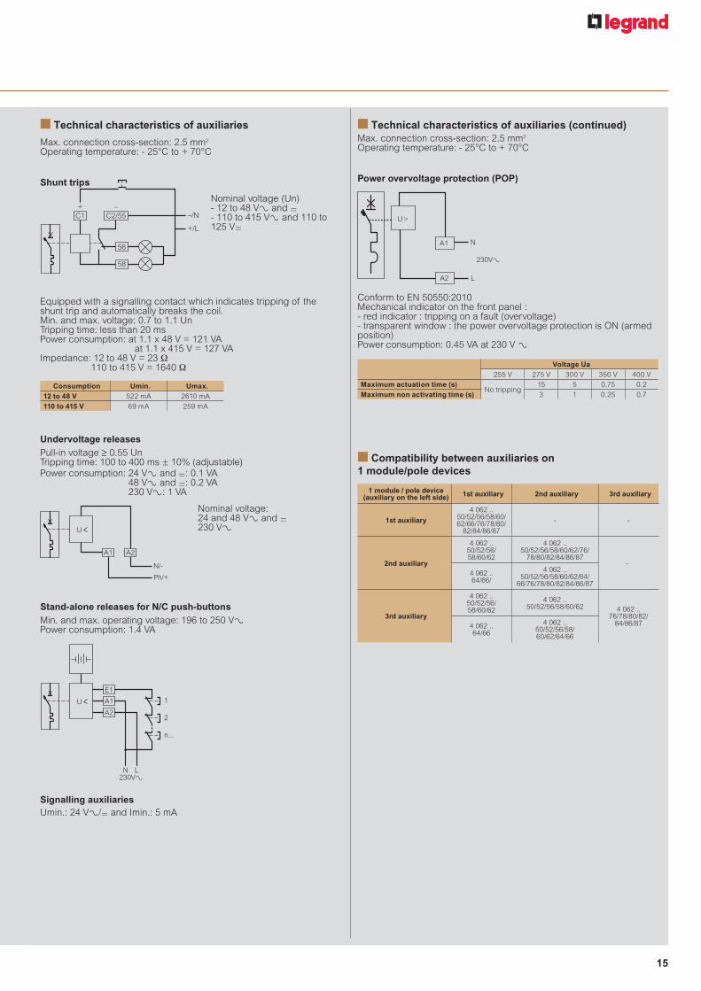
n Compatibility between auxiliaries on 1 module/pole devices
1 module / pole device (auxiliary on the left side) 1st auxiliary 2nd auxiliary 3rd auxiliary
1st auxiliary
4 062 ..50/52/56/58/60/62/66/76/78/80/
82/84/86/87
- -
2nd auxiliary
4 062 ..50/52/56/ 58/60/62
4 062 ..50/52/56/58/60/62/76/
78/80/82/84/86/87-
4 062 ..64/66/
4 062 ..50/52/56/58/60/62/64/
66/76/78/80/82/84/86/87
3rd auxiliary
4 062 ..50/52/56/ 58/60/62
4 062 ..50/52/56/58/60/62 4 062 ..
76/78/80/82/ 84/86/874 062 ..
64/66
4 062 ..50/52/56/58/ 60/62/64/66
Nominal voltage (Un)- 12 to 48 V± and =- 110 to 415 V± and 110 to 125 V=
Undervoltage releasesPull-in voltage ≥ 0.55 UnTripping time: 100 to 400 ms ± 10% (adjustable)Power consumption: 24 VA and =: 0.1 VA
48 VA and =: 0.2 VA 230 V±: 1 VA
Nominal voltage:24 and 48 VA and =230 V±
N/-
Ph/+
U
A2A1
Stand-alone releases for N/C push-buttonsMin. and max. operating voltage: 196 to 250 V± Power consumption: 1.4 VA
L230VAN
U
E1
A2
A1 1
2
n...
Signalling auxiliariesUmin.: 24 V±/= and Imin.: 5 mA
n Technical characteristics of auxiliaries
Max. connection cross-section: 2.5 mm2
Operating temperature: - 25°C to + 70°C
Shunt trips
Equipped with a signalling contact which indicates tripping of the shunt trip and automatically breaks the coil. Min. and max. voltage: 0.7 to 1.1 UnTripping time: less than 20 msPower consumption: at 1.1 x 48 V = 121 VA at 1.1 x 415 V = 127 VA Impedance: 12 to 48 V = 23 Ω
110 to 415 V = 1640 Ω
–/N
+/L
+ –C1
56
58
C2/55
Consumption Umin. Umax.12 to 48 V 522 mA 2610 mA
110 to 415 V 69 mA 259 mA
n Technical characteristics of auxiliaries (continued)Max. connection cross-section: 2.5 mm2
Operating temperature: - 25°C to + 70°C
Power overvoltage protection (POP)
Conform to EN 50550:2010Mechanical indicator on the front panel :- red indicator : tripping on a fault (overvoltage)- transparent window : the power overvoltage protection is ON (armed position)Power consumption: 0.45 VA at 230 V A
N
L
U>
A1
A2
230VA
Voltage Ua255 V 275 V 300 V 350 V 400 V
Maximum actuation time (s)No tripping
15 5 0.75 0.2
Maximum non activating time (s) 3 1 0.25 0.7
16
Cat.Nos Page N° Pack Cat.Nos Page N° Pack Cat.Nos Page N° Pack Cat.Nos Page N° Pack Cat.Nos Page N° Pack Cat.Nos Page N° Pack
Catalogue number index
0 227 00
0 227 97 13 1
4 033 00
4 033 50 10 10 53 10 10 55 10 10 56 10 10 57 10 10 58 10 10 59 10 10 60 10 10 61 10 10 62 10 10 63 10 10 80 10 5 83 10 5 85 10 5 86 10 5 87 10 5 88 10 5 89 10 5 90 10 5 91 10 5 92 10 5 93 10 5 95 10 1 98 10 1
4 034 00
4 034 00 10 1 01 10 1 02 10 1 03 10 1 04 10 1 05 10 1 06 10 1 07 10 1 08 10 1 10 10 1 13 10 1 15 10 1 16 10 1 17 10 1 18 10 1
4 034 19 10 1 20 10 1 21 10 1 22 10 1 23 10 1 27 10 10 30 10 10 32 10 10 33 10 10 34 10 10 35 10 10 36 10 10 37 10 10 38 10 10 39 10 10 40 10 10
4 035 00
4 035 21 10 5 24 10 5 26 10 5 27 10 5 28 10 5 29 10 5 30 10 5 31 10 5 32 10 5 33 10 5 34 10 5 38 10 1 41 10 1 43 10 1 44 10 1 45 10 1 46 10 1 47 10 1 48 10 1 49 10 1 50 10 1 51 10 1 55 10 1 58 10 1 60 10 1 61 10 1 62 10 1 63 10 1 64 10 1 65 10 1 66 10 1
4 035 67 10 1 68 10 1
4 040 00
4 040 78 10 10 81 10 10 82 10 10 83 10 10 84 10 10 85 10 10 86 10 10 87 10 10 88 10 10 89 10 10 90 10 10
4 041 00
4 041 06 10 5 09 10 5 10 10 5 11 10 5 12 10 5 13 10 5 14 10 5 15 10 5 16 10 5 17 10 5 18 10 5 20 10 1 23 10 1 24 10 1 25 10 1 26 10 1 27 10 1 28 10 1 29 10 1 30 10 1 31 10 1 32 10 1 48 10 1 51 10 1 52 10 1 53 10 1 54 10 1 55 10 1 56 10 1 57 10 1
4 041 58 10 1 59 10 1 60 10 1 64 10 10 67 10 10 69 10 10 70 10 10 71 10 10 72 10 10 73 10 10 74 10 10 75 10 10 76 10 10 77 10 10 98 10 5
4 042 00
4 042 01 10 5 03 10 5 04 10 5 05 10 5 06 10 5 07 10 5 08 10 5 09 10 5 10 10 5 11 10 5 15 10 1 18 10 1 20 10 1 21 10 1 22 10 1 23 10 1 24 10 1 25 10 1 26 10 1 27 10 1 28 10 1 49 10 1 52 10 1 54 10 1 55 10 1 56 10 1 57 10 1 58 10 1 59 10 1 60 10 1 61 10 1 62 10 1
4 062 00
4 062 50 12 1 52 12 1 56 12 1 58 12 1 60 12 1 62 12 1 64 12 1 66 12 1 76 12 1 78 12 1 80 12 1 82 12 1 85 12 1 86 12 1 87 12 1 88 13 1 89 13 1 90 13 1 91 13 1 92 13 1 93 13 1 95 13 1
4 063 00
4 063 03 13 2 04 13 2 05 13 1 06 13 1 07 13 10 10 13 1 11 13 1 12 13 1 13 13 3 19 13 1 20 13 1
4 115 00
4 115 02 11 1 09 11 1 10 11 1 11 11 1 12 11 1 19 11 1 20 11 1
4 115 21 11 1
22 11 1
29 11 1
30 11 1
31 11 1
32 11 1
52 11 1
59 11 1
60 11 1
61 11 1
62 11 1
64 11 1
65 11 1
66 11 1
67 11 1
74 11 1
75 11 1
76 11 1
77 11 1
4 117 00
4 117 07 11 1
08 11 1
09 11 1
10 11 1
17 11 1
18 11 1
19 11 1
20 11 1
27 11 1
28 11 1
29 11 1
30 11 1
64 11 1
65 11 1
66 11 1
67 11 1
74 11 1
75 11 1
76 11 1
77 11 1
84 11 1
85 11 1
86 11 1
87 11 1


EXB1
4039
- J
uly
2014
Head officeand International Department87045 Limoges Cedex - FranceTel.: + 33 (0) 5 55 06 87 87Fax: + 33 (0) 5 55 06 74 55
FOLLOW US ON
www.legrand.com
www.youtube.com/legrand
twitter.com/legrand_news