TWO WIRE 4 TO 20ma TRANSMITTER50.244.15.10/techlib/Flow Technology/FlowTech...4250 EAST BROADWAY...
33
4250 EAST BROADWAY ROAD ! PHOENIX, ARIZONA 85040 U.S.A. TELEPHONE (602) 437-1315 ! FAX (602) 437-4459 TWO WIRE 4 TO 20ma TRANSMITTER Installation, Operation and Maintenance Manual SERIAL NUMBER_________________________________ TM-87737 REV. H PUBLISHED BY FLOW TECHNOLOGY, INC. - JANUARY 1998 TWO WIRE 4 TO 20ma TRANSMITTER Installation, Operation and Maintenance Manual The specifications contained in this manual are subject to change without notice and any user of these specifications should verify from the manufacturer that the specifications are currently in effect. Otherwise, the manufacturer assumes no responsibility for the use of specifications that have been changed and are no longer in effect.
Transcript of TWO WIRE 4 TO 20ma TRANSMITTER50.244.15.10/techlib/Flow Technology/FlowTech...4250 EAST BROADWAY...

4250 EAST BROADWAY ROAD ! PHOENIX, ARIZONA 85040 U.S.A.TELEPHONE (602) 437-1315 ! FAX (602) 437-4459
TWO WIRE 4 TO 20ma
TRANSMITTER
Installation, Operationand
Maintenance Manual
SERIAL NUMBER_________________________________
TM-87737 REV. HPUBLISHED BY FLOW TECHNOLOGY, INC. - JANUARY 1998
TWO WIRE 4 TO 20maTRANSMITTER
Installation, Operationand
Maintenance Manual
The specifications contained in this manualare subject to change without notice andany user of these specifications shouldverify from the manufacturer that thespecifications are currently in effect. Otherwise, the manufacturer assumes noresponsibility for the use of specificationsthat have been changed and are no longerin effect.
Primary User
File Name: FlowTech_2WireTransmitter_TWAxxx_iom_D198

i
Thank you for selecting a FLOW TECHNOLOGY, INC. product for your flowmeasurement application.
Virtually every major commercial, government, and scientific organization is makinguse of our products, expertise and extensive technical support. This is a culminationof years of refinement in our flowmeter and calibrator designs, which has resulted inthe technological leadership in the flow measurements field which we enjoy.
We are proud of our quality products, our courteous service and welcome you, as avalued customer, to our growing family.

ii
WARRANTYLimited Warranty. Seller warrants thatgoods delivered hereunder will at delivery befree from defects in materials andworkmanship and will conform to seller'soperating specifications. Seller makes noother warranties, express or implied, andspecifically makes NO WARRANTY OFMERCHANTABILITY OR FITNESS FOR APARTICULAR PURPOSE.
Limitation of Liability. Seller's obligationunder the warranty shall be limited toreplacing or repairing at Seller's option, thedefective goods within twelve (12) monthsfrom the date of shipment, or eighteen (18)months from the date of shipment fordestination outside of the United States,provided that Buyer gives Seller proper noticeof any defect or failure and satisfactory proofthereof. Defective goods must be returned toSeller's plant or to a designated Seller'sservice center for inspection. Buyer willprepay all freight charges to return anyproducts to Seller's plant, or other facilitydesignated by Seller. Seller will deliverreplacements for defective goods to Buyerfreight prepaid. The warranty on saidreplacements shall be limited to the unexpiredportion of the original warranty. Goodsreturned to Seller for which Seller providesreplacement under the above warranty shallbecome the property of the Seller.
The limited warranty does not apply tofailures caused by mishandling ormisapplication. Seller's warranty obligationsshall not apply to any goods which (a) arenormally consumed in operation or (b) have anormal life inherently shorter than thewarranty period stated herein.
In the event that goods are altered or repairedby the Buyer without prior written approvalby the Seller, all warranties are void. Equipment and accessories not manufacturedby Seller are warranted only to the extent ofand by the original manufacturer's warranty. Repair or replacement goods furnishedpursuant to the above warranty shall remainunder warranty only for the unexpired portionof the original warranty period.
Should Seller fail to manufacture or delivergoods other than standard products appearingin Seller's catalog, Seller's exclusive liabilityand Buyer's exclusive remedy shall be releaseof the Buyer from the obligation to paypurchase price therefor.
THE FORGOING WARRANTIES ARE INLIEU OF ALL OTHER WARRANTIESWHETHER ORAL, WRITTEN, EXPRESSED,IMPLIED OR STATUTORY. IMPLIEDWARRANTIES OF FITNESS ANDMERCHANTABILITY SHALL NOT APPLYSELLER'S WARRANTY OBLIGATIONSAND BUYER'S REMEDIES THEREUNDER(EXCEPT AS TO TITLE) ARE SOLELY ANDEXCLUSIVELY AS STATED HEREIN. INNO CASE WILL SELLER BE LIABLE FORSPECIAL, INCIDENTAL ORCONSEQUENTIAL DAMAGE.
The total liability of Seller (including itssubcontractors) on any claim whether incontract, tort (including negligence whethersole or concurrent) or otherwise, arising outof or connected with, or resulting from themanufacture, sales, delivery, resale, repair,replacement or use of any goods or thefurnishing of any service hereunder shall notexceed the price allocable to the product orservice or part thereof which gives rise to theclaim.

iii
TM-87737 REVISIONS
DATE REVISION ECO NUMBER APPROVAL
AB
02/07/91 C 10144 M. Gray09/20/90 D 10820 M. Gray04/30/96 E 12332 B. Howard03/11/97 F 12752 E. Knowles01/30/98 G 13124 E. Knowles12/23/99 H 14537 T. Roy

iv
TABLE OF CONTENTS
SECTION TITLE PAGE1.0 SCOPE 12.0 PURPOSE 13.0 DESCRIPTION 14.0 OPERATION 25.0 APPLICATIONS 65.1 4 TO 30 mA CURRENT LOOP 65.2 APPLICATION CONNECTIONS 65.3 CURRENT SENSE RESISTOR USAGE 8
5.3.1 Choosing Sense Resistor Values 85.3.2 Load Resistance Considerations 95.4 RSET AND CSET 126.0 INSTALLATION 147.0 CALIBRATION 147.1 TEST EQUIPMENT REQUIRED 147.2 CALIBRATION CONNECTIONS 147.3 CALIBRATION ADJUSTMENTS 158.0 SPECIFICATIONS AND MODEL NUMBERING SYSTEM 179.0 TROUBLESHOOTING GUIDE 19
TABLE OF CONTENTS (Tables, Figures and Appendix)
SECTION TITLE PAGETABLE 1 RSET/CSET SELECTION AND SPAN RANGES 3TABLE 2 WIRE RESISTANCE CHART 10TABLE 3 4 TO 20 mA MODEL NUMBERING SYSTEM 18FIGURE 1 4 TO 20 mA BLOCK DIAGRAM 4FIGURE 2 CONNECTION BLOCK DIAGRAM 7FIGURE 3 TOTAL LOOP RESISTANCE VERSUS SUPPLY VOLTAGE 11FIGURE 4 RESPONSE TIME VERSUS MINIMUM FREQUENCY 13FIGURE 5 CALIBRATION WIRING DIAGRAM 16FIGURE 6 INSTALLATION DIAGRAM 25
APPENDIX A INSTALLATION OF INTRINSICALLY SAFE UNITS 26-29

1
1.0 SCOPE
This manual provides information and guidance for the installation and operation ofthe Two Wire 4 to 20 mA Transmitter. Application information for overall systemconnections and for general use is also provided.
2.0 PURPOSE
The contents of this manual provide the information necessary to install, calibrate,and operate the Two Wire 4 to 20 mA Transmitter. General information regardingthe different uses of the current loop as a hard-wired transmission medium iscontained in this manual. This manual assumes a working knowledge of turbineflowmeters.
3.0 DESCRIPTION
Turbine flowmeters are used to measure gas or liquid flow in pipe distributionsystems. The fluid passes through the turbine blades in the flowmeter, rotating theturbine. A sensing device, normally called a pickoff, resides on the outside of theflowmeter body, generating an electrical signal proportional to the speed of thespinning turbine blades.
The varying signal is not a strong signal therefore, under most circumstances,requires amplification and conditioning before being sent to receiving equipmentsuch as batchers, totalizers, or flow computers. The 4 to 20 mA Two-WireTransmitter serves as a signal-strengthening device.
The 4 to 20 mA Two-Wire Transmitter comes in a variety of enclosures. The mostversatile type is the potted module. Dimensions are 2.5 x 2.1 x 1.5 inches withmounting holes on 2.0 inch centers. This package is small, lightweight, and is easilyinstalled into other types of enclosures. For harsh or high moisture environments, aNEMA 4X enclosure can be provided. A 3-inch condulet is provided for explosion-proof requirements. A 3-1/2 inch polypropylene head can be ordered for use in thefood processing industry.
In addition to enclosure selection, the normal maximum frequency expected of the 4to 20 mA transmitter must be determined. From that, the frequency range may beselected. Also, the module must be configured at the factory for a Magnetic or a RFpickoff.

2
4.0 OPERATION
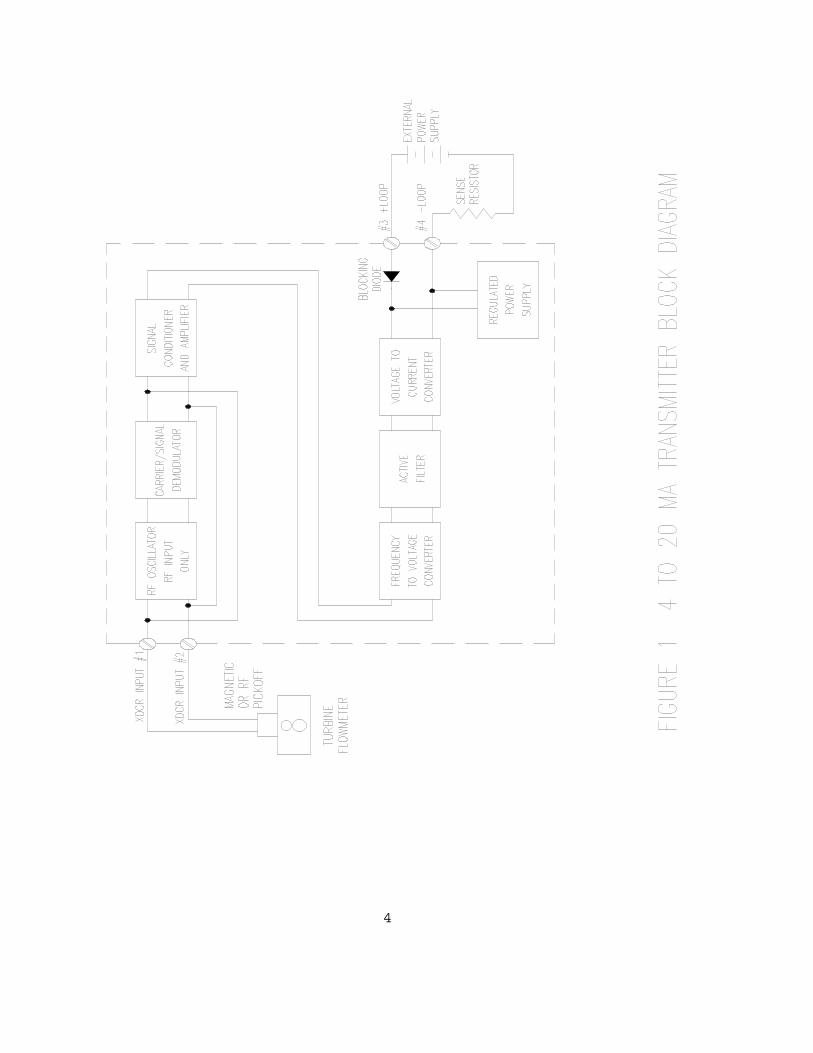
The Two Wire 4 to 20 mA Transmitter functional block diagram is shown in Figure 1. Allfunctions are common to both the RF and Magnetic Pickoff input products except for thefirst two function blocks, which are used only for the RF product.
The pickoff output wires connect directly to the transmitter inputs at XDCR input #1and #2. For a RF pickoff, these connections link a RF oscillator, operating atapproximately 50 kHz, to the pickoff. The pickoff then becomes a resonatinginductor, 1 mH, for the oscillator. The carrier produced has amplitude between 4 to 5Volts peak-to-peak.
As the turbine blades spin, they pass under the pickoff inductor, modulating thecarrier, and thereby producing a small signal on the carrier. The modulated signal isgenerally 10mV to 0.5V amplitude, depending on the size of the flowmeter bladesand the frequency output of the flowmeter.
The carrier is then stripped from the frequency signal by the de-modulator circuitry.The range of frequency operation of the de-modulator is 5 Hz to well over 4000 Hz.
For use with a magnetic pickoff, the Two-Wire Transmitter is configured to connectXDCR inputs #1 and #2 to the signal conditioner and amplifier. For the RF pickoff,the de-modulator circuitry is connected to this functional block. Input protection isincorporated up to 100-Volt peak transients. Input filtering is also added forsuppressing high frequency noise. The small pickoff signal is then amplified andedge conditioned to eliminate low level electrical noise.
The conditioned signal voltage is converted to a DC voltage through thefrequency-to-voltage circuitry. This frequency-to-voltage circuit requires Rset(resistor set), a selectable, fixed resistor that can be set to the maximum frequency(span) range. See Table 1 for the resistor selections. The maximum flowmeterfrequency can be set with the span adjustment. The range of the span adjustments arealso shown in Table 1. The response times shown are typical for a step-input changegiving an output within 90% of actual.

3
TABLE 1
RSET AND CSET SELECTION
Range Span Adjust Min. Freq RSET CSET Response Range in HZ in HZ Time Number
3001 to 4000 50 20.0K OHMS 0.15 uF 50 mSEC 01
2100 to 3000 50 26.7K OHMS 0.15 uF 50 mSEC 02
1470 to 2099 50 38.3K OHMS 0.15 uF 50 mSEC 03
1030 to 1469 25 54.9K OHMS 0.47 uF 150 mSEC 04
720 to 1029 25 76.8K OHMS 0.47 uF 150 mSEC 05
500 to 719 25 110K OHMS 0.47 uF 150 mSEC 06
350 to 499 15 162K OHMS 1.5 uF 500 mSEC 07
245 to 349 15 232K OHMS 1.5 uF 500 mSEC 08
170 to 244 15 324K OHMS 4.7 uF 1.5 mSEC 09
120 to 169 5 475K OHMS 4.7 uF 1.5 mSEC 10
81 to 119 5 665K OHMS 15 uF 4 SEC 11
50 to 80 5 1.00M OHMS 15 uF 4 SEC 12
4
5
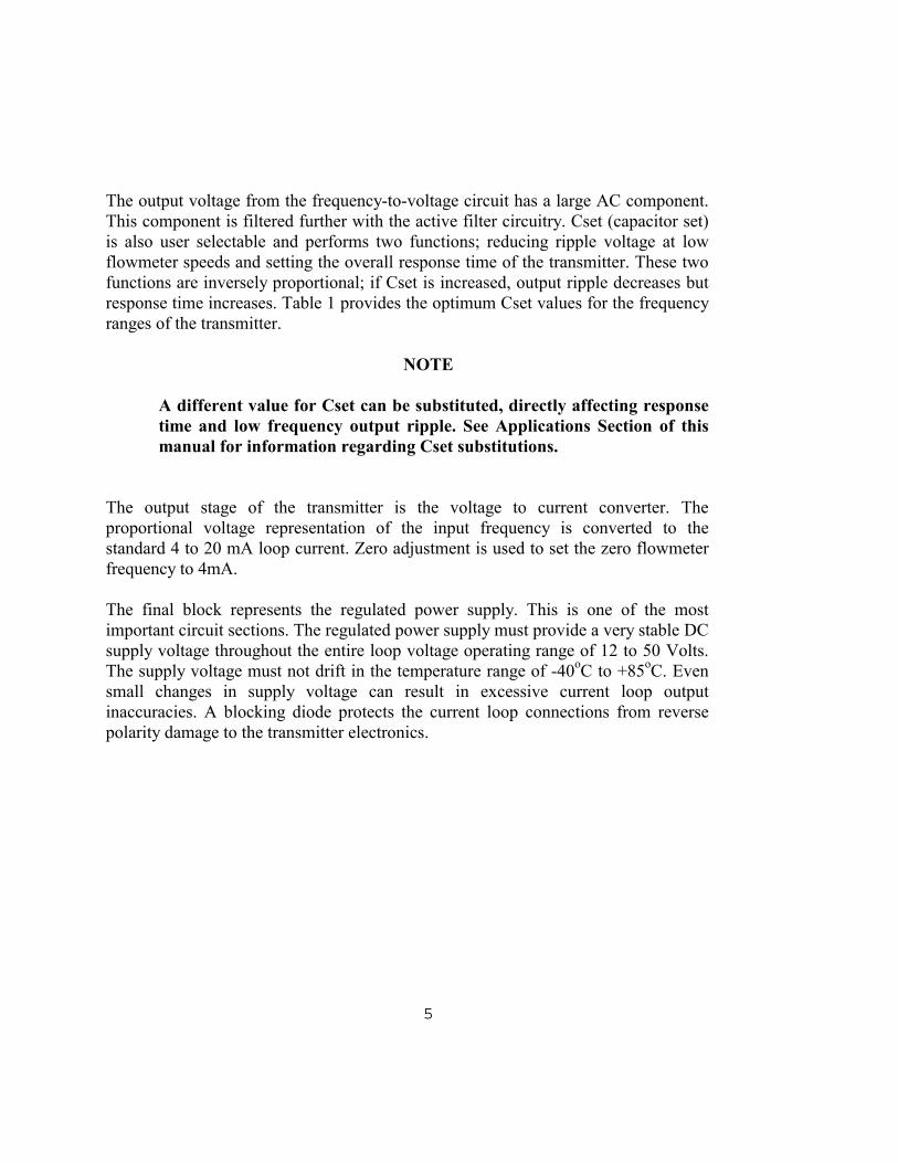
The output voltage from the frequency-to-voltage circuit has a large AC component.This component is filtered further with the active filter circuitry. Cset (capacitor set)is also user selectable and performs two functions; reducing ripple voltage at lowflowmeter speeds and setting the overall response time of the transmitter. These twofunctions are inversely proportional; if Cset is increased, output ripple decreases butresponse time increases. Table 1 provides the optimum Cset values for the frequencyranges of the transmitter.
NOTE
A different value for Cset can be substituted, directly affecting responsetime and low frequency output ripple. See Applications Section of thismanual for information regarding Cset substitutions.
The output stage of the transmitter is the voltage to current converter. Theproportional voltage representation of the input frequency is converted to thestandard 4 to 20 mA loop current. Zero adjustment is used to set the zero flowmeterfrequency to 4mA.
The final block represents the regulated power supply. This is one of the mostimportant circuit sections. The regulated power supply must provide a very stable DCsupply voltage throughout the entire loop voltage operating range of 12 to 50 Volts.The supply voltage must not drift in the temperature range of -40oC to +85oC. Evensmall changes in supply voltage can result in excessive current loop outputinaccuracies. A blocking diode protects the current loop connections from reversepolarity damage to the transmitter electronics.

6
5.0 APPLICATIONS 5.1 4 TO 20 mA CURRENT LOOP
The 4 to 20 mA current loop is a method of connecting a signal generating device, inthis case a turbine flowmeter, to receiving equipment for processing. Current looptransmission is widely accepted and used in the industrial controls environment.
A current loop consists of an inexpensive twisted wire pair from transmitter toreceiver. A current level instead of a voltage level is used, making the transmittedsignal unaffected by noise voltages or contact potentials. Current level transmissioneliminates crosstalk. Voltage drops caused by the wire resistances do not causemeasurement errors. Also, using a 4 to 20 mA range for the loop allows low currentsand low voltages for use in hazardous environments. Finally, a mis-connection orbroken line, 0 mA, can be distinguished from a zero reading of 4 mA, simplifyingproblem diagnosis.
5.2 APPLICATION CONNECTIONS
Figure 2 shows the connections necessary for a typical flowmeter transmitter system.The XDCR inputs #1 and #2 are for the pickoff wires. The pickoff is a non-polarizeddevice, a 1mH inductor, with wires that may be attached in either order. Wire lengthshould be 10 feet or less between the pickoff and the 4 to 20 mA transmitter. Twistedwire pairs are recommended.
For extremely electrically noisy environments or in cases where the flowmeter or thepickoff wiring must be mounted physically close to an electrical noise generator,such as a motor or engine ignition system, shielded twisted wire should be used, i.e.,Beldon #8761. The shield should be tied to the pickoff body or metal connector. Thewires can be encased in metal conduit as long as the conduit is electrically grounded.
The loop output connections should be made with correct polarities - the positiveloop wire to position #3 of the transmitter and the negative or return loop wire toposition #4. Wire length of the loop should be kept to 5000 feet or less. As with thepickoff wires, twisted wire pair is recommended, and for noisy environments,shielded twisted wire pair or metal conduit should be used.

7

8
5.3 CURRENT SENSE RESISTOR USAGE
The method for measuring the current in a 4 to 20 mA current loop is to convert thecurrent into a voltage using a current sense resistor.
Current loop receiving equipment such as batchers, totalizers, etc., incorporate thesense resistor at their current loop inputs. For custom applications or in the case ofuser selectable sense resistors, the following sections discuss the selection criteria.
5.3.1 Choosing Resistor Values
The most popular values for sense resistors are; 50, 100, 250, and 500 ohms. Thereason for choosing a low value such as the 50-ohm resistor is small voltage dropsacross the resistance, so less voltage is needed in the total current loop. 50 ohms isused when loop voltage requirements need to be low. Large value resistors such as500 ohms are used to develop large sense voltages for increased measurementaccuracy.
The equation used to determine voltage across the sense resistor is; loop sensevoltage = I loop x sense R
Example: The receiving equipment uses 250-ohm sense resistors. Calculate theloop voltage at 4 mA (0 Hz flowmeter frequency), 12 mA (1/2 maxflowmeter frequency), and 20 mA (max flowmeter frequency).
loop sense voltage = 4 mA x 250 ohms = 1 Volt (no flow)
loop sense voltage = 12 mA x 250 ohms = 3 Volts (1/2 full flow)
loop sense voltage = 20 mA x 250 ohms = 5 Volts (full flow)
As can be seen from the calculations, the range of loop sense voltage is from 1 V to 5V, or a compliance of 4 Volts. The 50-ohm sense resistor has a range of 0.2 Volt to 1Volt or a compliance of 0.8 Volts.
A sense resistor needs accuracy and temperature stability. It is recommended that theresistor selected is a metal film type, 0.1% tolerance, 25ppm-temperature coefficient,and 1/8 to 1/4-Watt power capability.

9
5.3.2 Load Resistance Considerations
The operating loop voltage for the 4 to 20 mA transmitter is 12 Volts to 50 Volts.This is the minimum/maximum voltage to be applied under all operating conditionsand should not be exceeded. Operation below 12 Volts results in output inaccuraciesor transmitter shutdown. Above 50 Volts for extended periods can result in excessiveoverheating or even damage. The loop voltage should never go above 100 Volts forany length of time as permanent damage will result. This loop voltage is the voltagedirectly at the transmitter connections.
There are two considerations for determining the actual loop voltage at thetransmitter.
Minimum Source Loop Voltage = 12 VDC + I max X R total = 12 VDC + 20 mA X
(R wiring + R loop) Maximum Source Loop Voltage = 50 VDC + I min X R total = 50 VDC + 4 mA X (R wiring + R loop)
where: R wiring is the DC wire resistance (See Table 2)
R loop is the loop voltage resistor used to sense the loopcurrent
I max is the maximum loop current of 20 mA
I min is the minimum loop current of 4 mA
12 VDC is the minimum transmitter voltage allowable(See Figure 3)
50 VDC is the maximum transmitter voltage allowable
Example: Calculate loop voltage and verify that it falls within 12 VDC to 50VDC for the following system; wire loop resistance of 600 ft (300 ftto the transmitter and 300 ft back) #22 gauge wire, sense resistor of250 ohms.
First check the minimum source loop voltage.
From Table 2, the wire resistance of #22 gauge wire is 0.01614 ohmsper foot. Multiply by 600 ft = 9.684 ohms total.

10
TABLE 2
WIRE RESISTANCE CHART
STANDARDCOPPERWIRE AWG
OHMS PER1000 FEET
OHMS PER100 FEET
OHMS PERFOOT
18 6.39 .639 .0063919 8.05 .805 .0080520 10.15 1.015 .0101521 12.80 1.280 .0128022 16.14 1.614 .0161423 20.36 2.036 .0203624 25.67 2.567 .0256725 32.37 3.237 .0323726 40.81 4.081 .0408127 51.47 5.147 .0514728 64.90 6.490 .0649029 81.83 8.183 .0818330 103.2 10.32 .103231 130.1 13.01 .130132 164.1 16.41 .1641

11
Figure 3. Total Loop Resistance Versus Supply Voltage.
12
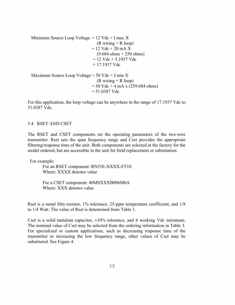
Minimum Source Loop Voltage = 12 Vdc + I max X (R wiring + R loop)
= 12 Vdc + 20 mA X (9.684 ohms + 250 ohms)
= 12 Vdc + 5.1937 Vdc = 17.1937 Vdc
Maximum Source Loop Voltage = 50 Vdc + I min X (R wiring + R loop) = 50 Vdc + 4 mA x (259.684 ohms) = 51.0387 Vdc For this application, the loop voltage can be anywhere in the range of 17.1937 Vdc to51.0387 Vdc.
5.4 RSET AND CSET
The RSET and CSET components set the operating parameters of the two-wiretransmitter. Rset sets the span frequency range and Cset provides the appropriatefiltering/response time of the unit. Both components are selected at the factory for themodel ordered, but are accessible in the unit for field replacement or substitution.
For example: For an RSET component: RN55E-XXXX-FT10. Where: XXXX denotes value
For a CSET component: 40MSXXXB006M0A Where: XXX denotes value
Rset is a metal film resistor, 1% tolerance, 25-ppm temperature coefficient, and 1/8to 1/4 Watt. The value of Rset is determined from Table 1.
Cset is a solid tantalum capacitor, ±10% tolerance, and 6 working Vdc minimum.The nominal value of Cset may be selected from the ordering information in Table 3.For specialized or custom applications, such as decreasing response time of thetransmitter or increasing the low frequency range, other values of Cset may besubstituted. See Figure 4.

13
Figure 4. Response Time Versus Minimum Frequency.

14
6.0 INSTALLATION
The Two Wire 4 to 20 mA Transmitter is available in a variety of packages; pottedmodule, NEMA 4X enclosure and polypropylene or explosion proof condulet. Thefirst step to installing the transmitter is choosing a suitable mounting location for thepackage. The potted module may be located up to 10 wire feet from the pickoff. Theother packages are normally attached directly to the pickoff but also have the same10-wire feet restriction when mounted away from the flowmeter/pickoff.
The wire connections are shown in Figure 2. For a detailed explanation of wireconnections, See Section 5.2.
ZERO and SPAN are factory set and should not need further calibration.
7.0 CALIBRATION
All tests shall be conducted at normal ambient temperatures.
7.1 TEST EQUIPMENT REQUIRED
Digital Multimeter - Data Precision 2590 or equivalent. Frequency Generator - Wavetek 171 or equivalent. Oscilloscope-Tektronix 2235 orequivalent 24VDC Power Supply - Lambda LQ-522 or equivalentLFA Simulator: (RF input TWA only) (May be purchased from
Flow Technology, Inc. Part Number 01-17484-101)249W 1% resistor
7.2 CALIBRATION CONNECTIONS Set a low impedance output (50W) of the frequency generator to 50mV peak-to-peaksine wave for a MAG TWA or 1V peak-to-peak for a RF TWA. If the TWA to betested has RF input, connect the LFA simulator to the low impedance output of thefrequency generator. With test leads, connect the output (or simulator) to terminals 1and 2 of the TWA. Make sure that the common (negative) lead of the frequencygenerator is connected to terminal 2.
Connect one end of the 249W resistor to terminal 4 of the TWA. Connect thepositive lead of the current meter to the other end of the 249W resistor. Connect thenegative lead of the current meter to the negative side of the power supply. Connectthe positive lead of the power supply to terminal 3 of the TWA.

15
7.3 CALIBRATION ADJUSTMENTS
Adjust the power supply to 24Vdc. Set the frequency generator to 0Hz. Adjust thezero potentiometer R22 of the TWA to 4.00mA ±.01mA maximum. Set the generatorto the maximum span range for TWA model 01 through 12. Adjust the spanpotentiometer R24 to 20.00mA ±.01mA maximum.
Set the generator to 1/2 the maximum span frequency of the TWA. The TWA mustbe 12.00mA ±.02 mA maximum or the unit is out of specification.
If the TWA is calibrated to a specific flowmeter, go through each data pointfrequency on the flowmeter data sheet and verify the milliamp output reading within±.02mA maximum.

16
Figure 5. Calibration Wiring Diagram.

17
8.0 SPECIFICATIONS AND MODEL NUMBERING SYSTEM
A list of the general specifications, the Model Numbering System, Table 3, isprovided in this Section.
Linearity ±0.1% of Reading (typical),±0.1% of Span (maximum)
Overall Accuracy 0.1% of Span(Includes linearity, repeatability, and calibration errors)
Temperature Stability Less than 0.01% of reading per oC
Input Sensitivity:Magnetic Input 5 mV RMSRF Input 10 mV RMS
* Supply Voltage 12 Vdc to 50 Vdc
Temperature Range -40oC to +85oC
Zero Adjustment ±0.2Ma
* Models with CE Approval through the European Community, the voltage supplyshould be at + 24 vdc +/- 1.

18
TABLE 3
4 TO 20 mA MODEL NUMBERING SYSTEM
TWA -- ---- -- ---- -- --- --- -- -- -- -- BASIC MODEL NUMBER INPUT TYPES A = MAGNETIC C = FTI RF ENCLOSURE TYPE 3 = POLYPROPYLENE CONDULET 4 = POTTED MODULE WITH MOUNTING HOLES 6 = NEMA 4X 9 = CLASS I, GROUP B CONDULET RANGES 01 = SPAN ADJUST 3001 TO 4000 HZ, MIN FREQ = 50 HZ 02 = SPAN ADJUST 2100 TO 3000 HZ, MIN FREQ = 50 HZ 03 = SPAN ADJUST 1470 TO 2099 HZ, MIN FREQ = 50 HZ 04 = SPAN ADJUST 1030 TO 1469 HZ, MIN FREQ = 25 HZ 05 = SPAN ADJUST 720 TO 1029 HZ, MIN FREQ = 25 HZ 06 = SPAN ADJUST 500 TO 719 HZ, MIN FREQ = 25 HZ 07 = SPAN ADJUST 350 TO 499 HZ, MIN FREQ = 15 HZ 08 = SPAN ADJUST 245 TO 349 HZ, MIN FREQ = 15 HZ 09 = SPAN ADJUST 170 TO 244 HZ, MIN FREQ = 15 HZ 10 = SPAN ADJUST 120 TO 169 HZ, MIN FREQ = 5 HZ 11 = SPAN ADJUST 81 TO 119 HZ, MIN FREQ = 5 HZ 12 = SPAN ADJUST 50 TO 80 HZ, MIN FREQ = 5 HZ
AGENCY APPROVAL TYPE FMI = FACTORY MUTUAL FMC = FACTORY MUTUAL/EUROPEAN COMMUNITY * CE = EUROPEAN COMMUNITY * IS = INTRINSICALLY SAFE CIS = EUROPEAN APPROVAL AND INTRINSICALLY SAFE
* CLASS I, GROUP B CONDULET ONLY

19
9.0 TROUBLESHOOTING GUIDE
The 4 to 20 mA transmitters are reliable devices and many of the problems that occurduring operation are the result of improper installation and/or calibration.
In the following pages, a guide shows some of the common problems that occurduring the use of 4 to 20 mA transmitters.
Various causes are given for each problem including a description of the cause andthe corrective action to be taken.
9.1 OUTPUT HIGH
PROBABLE CAUSE OPERATING CONDITIONS CORRECTIVE ACTIONSImproper ElectricalInstallation
Improper hook-up of cableshields.
OR
Voltage spikes on signals
Check for ground noise that can be mistakenas a flowmeter signal.
Check for transients and spikes that can bemistaken as a flowmeter signal.
Improper Calibration Maximum flowmeter frequencygenerates greater than 20.0 mA.
Recalibrate

20
9.2 OUTPUT LOW
PROBABLE CAUSE OPERATING CONDITIONS CORRECTIVE ACTION
Distorted Signals Magnetized rotor (Hint: Erroris some multiple of magnetizedblades divided by number ofrotor blades.NX = 1
# of blades).
OR
RF Amplifier to flowmetermismatch
Check for unequal signal in repeat pattern.
Degauss rotor blades.
Check for electrical mismatch between RFcircuitand the flowmeter
Varying Signal Amplitude Electronics does notdetect some pulses
Check to see if the signals produced by the rotorblades are individual pulses. Replace rotor ifpulses are not differentiated from each other
Noise Pickup AC signals overrideflowmeter signals and aredetected as pulses.
Check to see if large noise signal from motor orrelay is preventing the detection of pulses. Check for 60 Hz signals that attenuate oroverride flowmeter signals.
Improper Calibration Maximum flowmeterfrequency reads less than20.0 mA.
OR
0 flowmeter frequencyreads less than 4 mA
Recalibrate.
Recalibrate.

21
OUTPUT LOW (continued)
PROBABLE CAUSE OPERATING CONDITIONS CORRECTIVE ACTIONWeak FlowmeterSignal
Weak flowmeter signal is notdetected by electronics
Check for weak flowmeter signal that may notbe detected above the noise level of theelectronics.
Improper ElectricalInstallation
Loose pickoff.
OR
Improper hook-up of cableshield.
Verify that the pickoff bottoms in the housingand secure locknut.
Check for ground loops that attenuate thesignals into the noise level.
9.3 ZERO OUTPUT
PROBABLE CAUSE OPERATING CONDITIONS CORRECTIVE ACTIONRF Transmitter Pickoff not connected or not
installed properly
OR
RF transmitter electronicsoverheated.
Check the pickoff. The pickoff must beconnected to the transmitter and be bottomedin the flowmeter housing.
Check that the RF transmitter is not placed inproximity of the flowmeter where the fluidtemperature can affect the RF transmitteroperation.

22
ZERO OUTPUT (continued)
PROBABLE CAUSE OPERATING CONDITIONS CORRECTIVE ACTIONElectronics Malfunction Pickoff is working but the
transmitter gives 0 ma reading.Miswiring. Follow installation procedures toverify proper wiring.
Pickoff Defective orImproperly Installed
Open coil.
OR
Broken leads.
OR
Pickoff not bottomed inflowmeter housing
Perform resistance check on pickoff leads for 3to 3000 ohms.
Perform resistance check on pickoff leads forabove readings.
Finger tighten the pickoff in the flowmeterhousing and secure with locking nut.
Improper Wiring Flowmeter and transmitter arenot connected.
OR
Excessive distance fromflowmeter to transmitter
OR
Broken wires.
Check the wiring to see that the system isinterconnected.
Check the distance between components of thesystem. The maximum allowable distancebetween the pickoff and the transmitter is 10feet for magnetic and RF pickoffs.
Check for signals at both ends of theinterconnecting wire.

23
9.4 INTERMITTENT OPERATION
PROBABLE CAUSE OPERATING CONDITIONS CORRECTIVE ACTIONLoose Electrical Connections have worked
loose by vibration.Tighten connections.
Improperly InstalledPickoff
Pickoff may become loose inhousing.
Tighten pickoff.
Electronic Malfunction Flowmeter is working correctlybut electronics are operatingerratically
Test loop power supply and sense resistor forproper levels and operation.
High TemperatureElectronics
Electronics are heat sensitive. Relocate the electronics to reduce temperatureto an acceptable level.
9.5 NON-REPEATABLE OUTPUT
PROBABLE CAUSE OPERATING CONDITIONS CORRECTIVE ACTIONLoose ElectricalConnections
Connections have workedloose by vibration.
Tighten connections.
Improperly InstalledPickoff
Pickoff may become loose inhousing.
Tighten pickoff.
Electronic Malfunction Flowmeter is working correctlybut electronics are operatingerratically.
Test loop power supply and sense resistor forproper levels and operation.

24
9.6 CONSTANT METER OUTPUT
PROBABLE CAUSE OPERATING CONDITIONS CORRECTIVE ACTIONRF Transmitter to metermismatch
Pickoff and transmittermismatch provides constantnon-zero output due tooscillation of RF circuit.
Check data sheet. Secure proper components
Noise System is detecting a 60 Hz Acsignal
Check system shielding and ground.

25Figure 6. Installation Diagram.

26
APPENDIX A - INSTALLATION OF INTRINSICALLY SAFE UNITS
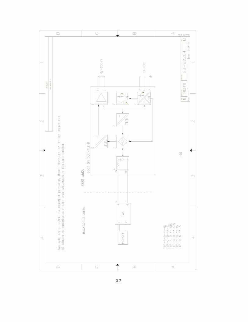
27

28