TWO DIRECTIONAL CYCLIC LOADING EXPERIMENTS IN … · TWO DIRECTIONAL CYCLIC LOADING EXPERIMENTS IN...
10
First European Conference on Earthquake Engineering and Seismology (a joint event of the 13 th ECEE & 30 th General Assembly of the ESC) Geneva, Switzerland, 3-8 September 2006 Paper Number: 1006 TWO DIRECTIONAL CYCLIC LOADING EXPERIMENTS IN A HOLLOW CYLINDER APPARATUS Juliane BUCHHEISTER 1 and Jan LAUE 2 SUMMARY Investigation of soil behaviour in laboratories should follow stress states and loading functions required for the representative field situation as closely as possible. In earthquake engineering, the investigated stress state simulated in the laboratory is often adapted to the testing devices available. Generally this includes cyclic or earthquake loading in one (shear) direction. With the new hollow cylinder apparatus at the Institute for Geotechnical Engineering at ETH Zurich, it is possible to apply bi-directional loading and any possible stress state in the soil prior to testing. This allows the reproduction of any stress state in the subsoil underneath a structure and the implementation of horizontal and vertical earthquake shaking. Experiments with fine sand are carried out to simulate a stress state close to a building under simultaneously applied bi-directional cyclic loading. Primary results are presented, focusing on the influence of stress state and the form and relative magnitude of bi-directional cyclic loading to be considered in soil structure interaction. Results of the first test series demonstrate the capability of the test apparatus. INTRODUCTION Structures founded on surface layers are highly affected by earthquake loading resulting from site amplification influenced by the strain dependency of the material behaviour. In almost saturated conditions of granular subsoil layers, pore water pressure may increase due to cyclic loading as the permeability conditions of the subsoil do not allow the water to be drained while the granular particles tend to rearrange themselves. The increase in pore water pressure goes along with a reduction of the effective stress, which can, in the worst case, initiate liquefaction. This caused severe foundation failures in many earthquakes [Ansal et al. 2003]. Research has mostly focused on the soil behaviour due to cyclic loading under free field conditions. Therefore either cyclic shear forces or torsional cyclic loads or axial cyclic loads were applied on mostly sand specimens. Less focus was given to the influence of stress state, especially to the shear forces in static boundary conditions and the influence of the loading function [Laue and Buchheister, 2005]. Ishihara and Yasuda [1975] reported earlier a greater resistance to liquefaction for a shock type than a vibration type of earthquake loading. Jordan [1986] found that the permeability and frequency influences the pore water development of fine sand using cyclic triaxial tests. In the frame of the research project, some of these influences will be studied with the new Hollow Cylinder device. A first attempt is made to investigate the influence of single and combined loading on a sand sample. HOLLOW CYLINDER APPARATUS The Hollow Cylinder Apparatus of the Institute for Geotechnical Engineering (Figure 1) is a complex testing device that differs from known dynamic triaxial as well as conventional hollow cylinder apparatuses [Hight et al. 1 ETH Zurich, Institute for Geotechnical Engineering, Wolfgang-Pauli-Str. 15, 8093 Zurich, Switzerland Email : [email protected] 2 ETH Zurich, Institute for Geotechnical Engineering, Wolfgang-Pauli-Str. 15, 8093 Zurich, Switzerland Email: [email protected]
Transcript of TWO DIRECTIONAL CYCLIC LOADING EXPERIMENTS IN … · TWO DIRECTIONAL CYCLIC LOADING EXPERIMENTS IN...

First European Conference on Earthquake Engineering and Seismology (a joint event of the 13th ECEE & 30th General Assembly of the ESC)
Geneva, Switzerland, 3-8 September 2006 Paper Number: 1006
TWO DIRECTIONAL CYCLIC LOADING EXPERIMENTS IN A HOLLOW CYLINDER APPARATUS
Juliane BUCHHEISTER1 and Jan LAUE2
SUMMARY
Investigation of soil behaviour in laboratories should follow stress states and loading functions required for the representative field situation as closely as possible. In earthquake engineering, the investigated stress state simulated in the laboratory is often adapted to the testing devices available. Generally this includes cyclic or earthquake loading in one (shear) direction. With the new hollow cylinder apparatus at the Institute for Geotechnical Engineering at ETH Zurich, it is possible to apply bi-directional loading and any possible stress state in the soil prior to testing. This allows the reproduction of any stress state in the subsoil underneath a structure and the implementation of horizontal and vertical earthquake shaking. Experiments with fine sand are carried out to simulate a stress state close to a building under simultaneously applied bi-directional cyclic loading. Primary results are presented, focusing on the influence of stress state and the form and relative magnitude of bi-directional cyclic loading to be considered in soil structure interaction. Results of the first test series demonstrate the capability of the test apparatus.
INTRODUCTION Structures founded on surface layers are highly affected by earthquake loading resulting from site amplification influenced by the strain dependency of the material behaviour. In almost saturated conditions of granular subsoil layers, pore water pressure may increase due to cyclic loading as the permeability conditions of the subsoil do not allow the water to be drained while the granular particles tend to rearrange themselves. The increase in pore water pressure goes along with a reduction of the effective stress, which can, in the worst case, initiate liquefaction. This caused severe foundation failures in many earthquakes [Ansal et al. 2003]. Research has mostly focused on the soil behaviour due to cyclic loading under free field conditions. Therefore either cyclic shear forces or torsional cyclic loads or axial cyclic loads were applied on mostly sand specimens. Less focus was given to the influence of stress state, especially to the shear forces in static boundary conditions and the influence of the loading function [Laue and Buchheister, 2005]. Ishihara and Yasuda [1975] reported earlier a greater resistance to liquefaction for a shock type than a vibration type of earthquake loading. Jordan [1986] found that the permeability and frequency influences the pore water development of fine sand using cyclic triaxial tests. In the frame of the research project, some of these influences will be studied with the new Hollow Cylinder device. A first attempt is made to investigate the influence of single and combined loading on a sand sample.
HOLLOW CYLINDER APPARATUS The Hollow Cylinder Apparatus of the Institute for Geotechnical Engineering (Figure 1) is a complex testing device that differs from known dynamic triaxial as well as conventional hollow cylinder apparatuses [Hight et al. 1 ETH Zurich, Institute for Geotechnical Engineering, Wolfgang-Pauli-Str. 15, 8093 Zurich, Switzerland Email : [email protected] ETH Zurich, Institute for Geotechnical Engineering, Wolfgang-Pauli-Str. 15, 8093 Zurich, Switzerland Email: [email protected]

submitted to the 1st European Conference on Earthquake Engineering and Seismolog (1stECEES),2006,Schweiz
1983; Vaid et al. 1990]. It is possible to apply bi-directional static and dynamic loading in vertical and torsional direction independently as well as in a coupled form. The potential for both load and deformation control allows the testing of deformation patterns, as measured in earthquakes as well as it allows defined rotation of principal stresses (see Table 1).
Table 1: Specifications for the maximal loading conditions static and dynamic for the HCA of the IGT
max. static max. dynamic Axial load 63 kN 50 kN
Displacement +/- 50 mm +/- 50 mm Torque 250 Nm 200 Nm
Rotation +/- 20° +/- 20° Confining pressure (internal and external) 1000 kPa 1000 kPa
Frequency axial 10 Hz 10 Hz Frequency torsional 10 Hz 10 Hz
The apparatus allow testing of two different sample sizes (100 x 50 x 200 and 150 x 80 x 300 respectively; outer diameter x inner diameter x height in mm). The device can also be transferred back to a triaxial testing device using full samples. The vertical and torsional load is applied by two hydraulic jacks controlled by servo-electronic valves. Both jacks can be independently controlled to permit stress paths and strain rates to be applied. The cell pressures (inner and outer cell pressure as well as back pressure) are applied by a set of step-motors (Figure 1a). Pore Pressure Transducers are mounted directly adjacent to the bottom and the top of the sample. A resolution of 0.5 kPa can be achieved for a transducer with a maximum pressure of 150 kPa. One displacement transducer and one angular transducer, obtaining the vertical deformation and the angle of rotation respectively, are mounted on top of the cell. They are accompanied by another set of transducers obtaining the vertical displacement (max. 7 mm) and rotation (max. 5°) inside the cell at the middle of the height of the specimen. The measurement accuracy is less than 1% and a resolution of 0.0001 mm is possible. The device is computer controlled using an in house software program. In addition, manual control is possible for the static features. Electronic regulation of the experiment during testing is possible and measurement frequencies up to 20 kHz might be reached. For the tests presented here, a scan rate of 100 Hz has been chosen.
(a) (b) (c)
Figure 1: Hollow Cylinder Apparatus of the Institute for Geotechnical Engineering at ETH Zurich (a) pressure control unit (b) hydraulic load frame (c) computer control system
2/10
submitted to the 1st European Conference on Earthquake Engineering and Seismolog (1stECEES),2006,Schweiz
HCA TESTS The material tested is poorly graded fine sand from Australia (CIM Cook Industrial Materials Pty. Ltd., Amcor, M082). It consists of purely quartz minerals (SiO2). The grain size distribution curve is presented in Figure 2.
0
10
20
30
40
50
60
70
80
90
100
0.001 0.01 0.1 1 10
grain size [mm]
perc
ent f
iner
[%]
Figure 2: Grain size distribution curve of the testing material
The shape of the grains is sub-rounded to rounded, while some are sub-angular and have a tendency to be columnar. The characteristic parameters are summarized in Table 2 and a microscopic figure of the sand can be found in Figure 3.
Table 2: Soil parameter for Australian fine sand
USCS SP d10 0.14 mm d30 0.21 mm D50 0.23 mm d60 0.25 mm Cu 1.79 Ck 1.26 k (after Hazen) 2.3 10-4 m/s δs 2.65 g/cm3
δd min 1.510 g/cm3
δd max 1.729 g/cm3
ϕ’ (approximate) 35°
Figure 3: Shape of the sand grains (magnification 40x, environmental scanning electron microscopy)
3/10

submitted to the 1st European Conference on Earthquake Engineering and Seismolog (1stECEES),2006,Schweiz
Testing procedure In the experiments presented here, the specimens were prepared using the air pluviation method in order to simulate loose sedimented sand. Particle segregation is not assumed due to the poorly graded material (Figure 2). The soil samples were prepared directly on the base plate of the hollow cylinder apparatus. This minimizes further sample disturbance. A small vacuum of -30 kPa was applied while removing the emplacement forms and superimposing the cell mantle. After filling the inner and outer cell simultaneously with de-aired water with a small hydraulic gradient, the specimen was saturated. B-values were very small (B=0.2) even at back pressures of 500 kPa. After the conducted test the water content was measured and a degree of saturation Sr between 80% and 90% was reached indicating almost saturation under test conditions. This is also be proven by observing the water-budget of the specimen, while saturating the sample. A small water pressure of 5kPa was applied at the bottom drainage plate and exactly the same amount of water that was pressed into the sample was flowing out at the top drainage plate of the sample. Even at tests conducted beforehand no increase of the B-value could be reached with time with leaving the sample three days under constant conditions before testing. After Black and Lee [1973], the B-value for dense Ottawa sand, which seems to be comparable from the view of grain size distribution, is only 0.2 for a saturation of 99% at a back pressure of 20 psi ( 138 kPa). They also state that is not possible to reach a B-value of 1 for very stiff grains. Thus, their studies on sand were limited to values below Sr=95% in a triaxial sample of always the same size. The sample geometry in a HCA could be of importance to the procedure of checking saturation and other methods need to be developed here. Consolidation time for the sand was approximately below 1 second, calculated with an approximated cv= 0.69m2/s.
Sample properties The relevant geometric sample properties are summarized in Table 3. The relative density for all tested specimens was medium dense. The cell temperature was constant for each test and remained between 20.7° and 22.5° Celsius.
Table 3: Geometric sample properties cyclic axial test cyclic torsional test cyclic axial and torsional test sample height [mm] 191.50 198.41 196.16 sample outer diameter [mm] 98.44 98.95 96.81 ρd [g/cm3] 1.594 1.606 1.611 e [ - ] 0.662 0.650 0.645 The anisotropic stress state in the sample before the cyclic loading was set to σz = 42 – 54 kPa and σr = 66 – 68 kPa. The effective consolidation ratio (radial effective stresses / axial effective stresses) was between 1.23 and 1.63. The outer cell pressure pa is equal to the inner cell pressure pi resulting in a horizontal effective stress of σr = pa = pi. The vertical effective stress is shown in Figure 4 with the upper drainage plate and loading ram (ub = back pressure):
2 1 3
2 3
z a iz b
F p (A A ) A p' uA A
+ − −σ = −
−
The shear stress is calculated as: 3 33
2 a i
T(r r )
τ =π −
with the torsional force T, inner radius ri and outer radius ra.
The cyclic loading was applied under displacement control in a sinusoidal format. In order to simulate an earthquake type of loading, different frequencies were chosen for torsion and vertical strains. In torsion, a frequency of 1 Hz was applied with a shear strain of +/- 0.18 %. In the vertical direction, a frequency of 0.7 Hz was taken with a strain rate of 0.5%. The choice of frequency applied adapts the usually 30% lower value of vertical acceleration in an earthquake [e.g. in SIA 261 2003].
4/10

submitted to the 1st European Conference on Earthquake Engineering and Seismolog (1stECEES),2006,Schweiz
Figure 4: Dimensions and pressures inside (pi) and outside (pa) the hollow cylinder specimen with upper drainage plate and loading ram
HCA TEST RESULTS
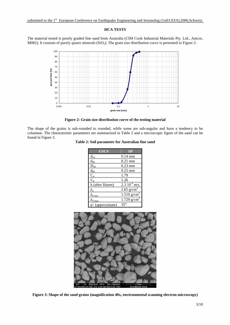
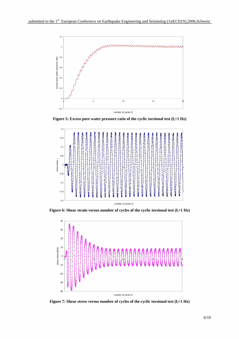
Cyclic torsional loading The cyclic torsional load test was conducted with an amplitude of 1° and 1 Hz. In Figure 5, the development of the pore water pressure is illustrated. After 8 cycles, 95% of the excess pore water increment (Nu95) was reached. A maximum shear stress of 40 kPa was needed to apply 0.18 % single amplitude (SA) of shear strain (Figure 6 and Figure 7). After 8 cycles, the shear stress drops to ¼ of the maximum undrained shear stress, that is τ = 9 kPa (Figure 8). The maximum cyclic stress ratio (CSR), defined as shear stress over the effective consolidation stress, was determined to be CSR=0.59.
5/10
submitted to the 1st European Conference on Earthquake Engineering and Seismolog (1stECEES),2006,Schweiz
-0.2
0
0.2
0.4
0.6
0.8
1
1.2
0 5 10 15 20
number of cycles N
exce
ss p
ore
wat
er p
ress
ure
ratio
Figure 5: Excess pore water pressure ratio of the cyclic torsional test (ft=1 Hz)
-0.2
-0.15
-0.1
-0.05
0
0.05
0.1
0.15
0.2
0 5 10 15 20
number of cycles N
shea
r stra
in γ
Figure 6: Shear strain versus number of cycles of the cyclic torsional test (ft=1 Hz)
-40
-30
-20
-10
0
10
20
30
40
0 5 10 15 20
number of cycles N
shea
r stre
ss [k
Pa]
Figure 7: Shear stress versus number of cycles of the cyclic torsional test (ft=1 Hz)
6/10

submitted to the 1st European Conference on Earthquake Engineering and Seismolog (1stECEES),2006,Schweiz
-40
-30
-20
-10
0
10
20
30
40
-0.2 -0.15 -0.1 -0.05 0 0.05 0.1 0.15 0.2
shear strain
shea
r stre
ss [k
Pa]
Figure 8: Shear stress versus shear strain of the cyclic torsional test (ft=1 Hz)
Cyclic axial loading The cyclic axial load test was conducted with an amplitude of 1 mm and 0.7 Hz. 5 cycles are needed to reach 95% of the excess pore water increment (Figure 9). A maximum vertical effective stress of 159 kPa was required to apply 0.5 % single amplitude of axial strain (Figure 10). After 5 cycles, the effective axial stress is almost zero. The maximum cyclic stress ratio (CSR), defined as half of the cyclic deviator stress over the effective consolidation stress, was determined to be CSR=0.67.
-0.2
0
0.2
0.4
0.6
0.8
1
1.2
0 5 10 15 20
number of cycles N
exce
ss p
ore
wat
er p
ress
ure
ratio
Figure 9: Excess pore water pressure ratio of the cyclic axial test (fv=0.7 Hz)
7/10

submitted to the 1st European Conference on Earthquake Engineering and Seismolog (1stECEES),2006,Schweiz
-0.6
-0.5
-0.4
-0.3
-0.2
-0.1
0
0.1
0.2
0.3
0.4
0.5
0.6
0 5 10 15 20
number of cycles N
axia
l stra
in
Figure 10: Axial strain versus number of cycles of the cyclic axial test (fv=0.7 Hz)
Cyclic axial and torsional loading The cyclic axial and torsional load test was conducted with an axial amplitude of 1 mm and 0.7 Hz and a torsional amplitude of 1° and 1 Hz. A maximum shear stress of 39 kPa was needed to apply 0.18 % SA shear strain and a maximum axial effective stress of 160 kPa was needed to apply a 0.51 % SA axial strain. Both values are almost equivalent to the single loading function, whereas an influence of the different functions on each other is recognizable; compare Figure 11 and Figure 12. After 5 vertical cycles or 8 torsional cycles, the effective shear stress is 18 kPa. The maximum cyclic stress ratio is averaged to be CSR=0.64, which is between the definition of the cyclic axial test resulting in a CSR=0.72 and the definition of the cyclic torsional test resulting in a CSR=0.56.
-0.25
-0.2
-0.15
-0.1
-0.05
0
0.05
0.1
0.15
0.2
0.25
0 5 10 15 20 25
time [s]
shea
r st
rain
Figure 11: Shear strain of the cyclic axial and torsional test (fv=0.7 Hz, ft=1 Hz)
8/10

submitted to the 1st European Conference on Earthquake Engineering and Seismolog (1stECEES),2006,Schweiz
-0.6
-0.5
-0.4
-0.3
-0.2
-0.1
0.0
0.1
0.2
0.3
0.4
0.5
0.6
0 5 10 15 20 25
time [s]
axia
l st
rain
Figure 12: Axial strain of the cyclic axial and torsional test (fv=0.7 Hz, ft=1 Hz)
HCA DISCUSSION AND OUTLOOK
Pore water pressure The development of the pore water pressure increment of all three tests is illustrated in Figure 13. The curves of the cyclic axial and the combined axial and torsional test are similar when comparing the excess pore water pressure increment. Both have higher peaks than the curve of the cyclic torsional test and the number of cycles to reach 95% liquefaction is almost the same.
-0.2
0
0.2
0.4
0.6
0.8
1
1.2
0 5 10 15 20 25
time [s]
exce
ss p
ore
wat
er p
ress
ure
ratio
cyclic axial testcyclic torsional testcyclic axial and torsional test
Figure 13: Excess pore water pressure ratio in all three loading tests.
9/10

submitted to the 1st European Conference on Earthquake Engineering and Seismolog (1stECEES),2006,Schweiz
Under the given stress conditions, the bi-directional loading showed no big influence on the soil behaviour compared to the one directional loading tests. Maybe other combinations of amplitude and frequency will have a noticeable influence, which will be investigated in the ongoing research. Earthquake functions that differ from known earthquake loading e.g. Kocaeli 1999 can have consequences on the material behaviour of soils as well. Stress states that are especially relevant for slopes and underneath buildings will also be investigated.
Sample preparation
Membrane effects were not taken into account. After Molenkamp and Luger [1981], the lateral restraint and penetration effect depends on the membrane thickness, mean grain size, pressure ratio, sample diameter and indentation. Since the grain size is small compared to the membrane thickness and diameter the indentation will be small. Additionally for a small pressure ratio the membrane effect will be minor, but for undrained triaxial tests the membrane effect could be relevant. The friction of the piston in the cell has been neglected so far but will be quantified and taken into account in the future based on inner and outer cell measurements. The sample preparation will be enhanced by longer saturation time and higher back pressures using an isotropic stress state to enable comparison.
ACKNOWLEDGEMENTS
The grants for the new HCA testing device provided to Prof. Sarah M. Springman by the Swiss National Science Foundation (R’EQUIP) and the ETH Zurich are greatly acknowledged. The work of Adi Zweidler, Ernst Bleiker, Heinz Buschor and Rafael Schuler for technical support to get the device into working condition and the funding of SNF (No. 200021-104027 - Management of Earthquake Risks using Condition Indicators) in the framework of the PhD project is also gratefully recognized.
REFERENCES Ansal, A., Springman, S., Studer, J. A., Oenalp, A., Erdik, M., Giardini, D., Sesetyan, K., Demircioglu, M.,
Akman, H., Fäh, D., Christen, A., Laue, J., Buchheister, J., Cetin, K. O., Siyahi, B., Fahjan, Y., Gülkan, P., Bakir, S., Lestuzzi, P., Elmas, M., Koeksal, D. and Goekce, O. (2003), Microzonation Pilot Studies for Adapazari and Gölcük / Adapazari ve Gölcük icin mikrobölgelme calismalari, Besinci Ulusal Deprem Mühendisligi Konferansi, Istanbul, Turkey
Black, D. K. and Lee, K. L. (1973), Saturating Laboratory Samples by Back Pressure, Journal of the Soil Mechanics and Foundations Division, ASCE, vol. 99, issue SM1, 75-93.
Hight, D. W., Gens, A. and Symes, M. J. (1983), The developement of a new hollow cylinder apparatus for investigating the effects of principal stress rotation in soils, Géotechnique, vol. 33, issue 4, 355-383.
Ishihara, K. and Yasuda, S. (1975), Sand liquefaction in hollow cylinder torsion under irregular excitation, Soils and Foundations, vol. 15, issue 1, 45-59.
Jordan, P. (1986), Einfluss der Belastungsfrequenz und der partiellen Entwässerungsmöglichkeit auf die Verflüssigung von Feinsand, Ruhr-Universität Bochum, Grundbau, Wasserwesen und Verkehrswesen.
Laue, J. and Buchheister, J. (2005), Load path and loading velocity as potential condition indicator for liquefaction of silty soils, 16th International Conference on Soil Mechanics and Geotechnical Engineering (16 ICSMGE), Osaka, Japan
Molenkamp, F. and Luger, H. J. (1981), Modeling and minimization of membrane penetration effects in tests on granular soils, Géotechnique, vol. 31, issue 4, 471-486.
SIA (2003), SIA 261 - Einwirkungen auf Tragwerke, report nr. SN 505 261, Schweizer Ingenieur- und Architektenverein, Zürich, Switzerland.
Vaid, Y. P., Sayao, A., Hou, E. and Negussey, D. (1990), Generalized stress-path-dependent soil behaviour with a new hollow cylinder torsional apparatus, Canadian Geotechnical Journal, vol. 27, issue 5, 601-616.
10/10